EP4174398A1 - A support bracket for equipment, in particular units for air-conditioning plants - Google Patents
A support bracket for equipment, in particular units for air-conditioning plants Download PDFInfo
- Publication number
- EP4174398A1 EP4174398A1 EP22203375.5A EP22203375A EP4174398A1 EP 4174398 A1 EP4174398 A1 EP 4174398A1 EP 22203375 A EP22203375 A EP 22203375A EP 4174398 A1 EP4174398 A1 EP 4174398A1
- Authority
- EP
- European Patent Office
- Prior art keywords
- bracket
- head
- opening
- screw type
- equipment
- Prior art date
- Legal status (The legal status is an assumption and is not a legal conclusion. Google has not performed a legal analysis and makes no representation as to the accuracy of the status listed.)
- Granted
Links
Images



Classifications
-
- F—MECHANICAL ENGINEERING; LIGHTING; HEATING; WEAPONS; BLASTING
- F24—HEATING; RANGES; VENTILATING
- F24F—AIR-CONDITIONING; AIR-HUMIDIFICATION; VENTILATION; USE OF AIR CURRENTS FOR SCREENING
- F24F13/00—Details common to, or for air-conditioning, air-humidification, ventilation or use of air currents for screening
- F24F13/32—Supports for air-conditioning, air-humidification or ventilation units
-
- F—MECHANICAL ENGINEERING; LIGHTING; HEATING; WEAPONS; BLASTING
- F16—ENGINEERING ELEMENTS AND UNITS; GENERAL MEASURES FOR PRODUCING AND MAINTAINING EFFECTIVE FUNCTIONING OF MACHINES OR INSTALLATIONS; THERMAL INSULATION IN GENERAL
- F16L—PIPES; JOINTS OR FITTINGS FOR PIPES; SUPPORTS FOR PIPES, CABLES OR PROTECTIVE TUBING; MEANS FOR THERMAL INSULATION IN GENERAL
- F16L3/00—Supports for pipes, cables or protective tubing, e.g. hangers, holders, clamps, cleats, clips, brackets
- F16L3/22—Supports for pipes, cables or protective tubing, e.g. hangers, holders, clamps, cleats, clips, brackets specially adapted for supporting a number of parallel pipes at intervals
- F16L3/221—Supports for pipes, cables or protective tubing, e.g. hangers, holders, clamps, cleats, clips, brackets specially adapted for supporting a number of parallel pipes at intervals having brackets connected together by means of a common support
Definitions
- the present invention relates to a support bracket for equipment, in particular to units for air-conditioning plants, having the features set out in the preamble of the main claim 1.
- the invention particularly, though in a non-exclusive manner, involves the field of bracket-like fixing devices for supporting the exchange groups for air-conditioning plants.
- the heat exchanger groups which are used in the air-conditioning plants and which supply the diffusors which are provided in the surrounding areas of the buildings to be air-conditioned, have to be arranged and supported outside the buildings or in any case relocated to such a position as to communicate with the exterior.
- brackets In order to fix these exchangers to the walls, the widespread use of typically L-shaped brackets which have such dimensions as to have suitable robustness is well-known, a pair of these brackets normally being sufficient, which brackets are fixed both directly to the walls and to guides which in turn are fixed to the walls.
- brackets are further provided with openings which define the seats for inserting fixing screws with which the equipment can be secured to the brackets themselves.
- brackets are made from metal material, wherein each of the bracket portions which form the L-shaped formation is configured with a U-shaped cross-section which is suitable for providing the member of the bracket with adequate resistance to the loads applied.
- brackets of this configuration the bracket portion which is provided for supporting and fixing the equipment item on the bracket which under operating conditions is arranged horizontally is provided with slotted through-holes, in which the fixing screws are inserted.
- these screws are inserted in the elongate holes, with the head of the screw arranged in a position under the bracket so as to engage with the extension pieces or anchoring feet of the equipment, and to allow the locking nut to be screwed from above to the threaded shank of the screw.
- the invention is directed towards these types of brackets and the main object is to provide a support bracket for equipment items, in particular air-conditioning plant units, which is structurally and functionally configured to overcome the limitations set out and so as to make the steps of anchoring the equipment items to the support brackets simple, rapid and convenient for the fitter.
- the bracket comprises a first and a second bracket portion which are arranged for anchoring the bracket to a wall and for supporting and fixing the equipment to the bracket, respectively, the first and second bracket portions being able to be secured to each other in an operating condition, in which they assume an L-shaped configuration suitable for supporting the equipment, there being defined on the second bracket portion a surface portion which is intended for the supporting contact of the equipment, the surface portion being provided with at least one through-opening which is in the form of an elongate slot, for engaging in a sliding manner with at least one respective screw type member which is intended to anchor the equipment on the corresponding bracket, the screw type member comprising a head and a threaded shank which extends from the head, wherein the screw type member comprises, in the region of the head, a pair of opposite seats, each seat being configured to be connected, with sliding engagement, to a corresponding peripheral edge of the through-opening so that the screw type member is retained in a manner slidingly guided along the opening, thereby preventing the screw type
- the through-opening has an elongate formation in a main longitudinal direction and has a widened portion in the region of at least one of the opposite longitudinal ends thereof with such an extent as to allow the insertion of the head of the screw type member through the widened portion of the opening and the sliding engagement of the head with the surface portion of the bracket along the slotted extent of the opening.
- each of the seats is defined by a first surface and a second surface which are parallel with and spaced apart from each other and which are connected to a third surface, the transverse thickness of the surface portion of the bracket being received between the first surface and the second surface and being abutted by the third surface.
- the third surface has a planar configuration and the distance between the pair of the third surfaces is selected in such a manner that the head is slidingly guided in terms of translation in the slotted opening without any substantial possibility of rotation about the main axis of the screw type member.
- the head is made from plastics material co-moulded on the threaded shank.
- each seat is defined in a main member of the head and the second surface is defined in a plate-like portion of the head arranged between the main member and the threaded shank.
- brackets there are provided in the brackets a pair of the slotted through-openings which are aligned at a predetermined distance in the longitudinal development direction.
- the second bracket portion is made from metal material or plastics material.
- FIG. 1 a first embodiment of a support bracket for equipment items, typically air-conditioning plant units (not illustrated), which is constructed according to the present invention.
- brackets 1 Normally, there is provision for a pair of brackets 1 to be provided in a parallel and spaced-apart relationship with suitable relative spacing in order to define the support and fixing surfaces of the equipment, even if different configurations are possible.
- the bracket 1 comprises a first and a second portion which are designated 2 and 3, respectively, and which are configured to be secured to each other at converging ends thereof in order to assume a square configuration which substantially extends in an L-like manner and which is suitable for performing the support function for the equipment.
- the securing system between the bracket portions 2, 3 may provide for using locking screws which are engaged in through-holes which are formed, in a corresponding position, on both bracket portions, for example, with the configuration shown in Figure 1 .
- Other blocking systems of the bracket portions or articulation portions with blocking in the extended L-shaped position are possible.
- the inventive concept forming the basis of the invention is further also applicable to support brackets in which the first portion and second portion 2, 3 are integral with each other, in a one-piece formation of the support bracket.
- the first bracket portion 2 therefore forms the vertical upright of the bracket which is provided for anchoring it, either directly to the wall or by means of coupling to a guiding cross-member which is in turn fixed to the wall, while the second portion 3 forms the horizontal arm of the bracket which is provided for supporting and fixing the equipment on the bracket.
- Each of the bracket portions 2 and 3 extends in a respective main longitudinal extent direction which is designated Y for the bracket portion 2 and X for the bracket portion 3, the bracket portion 3 extending between opposite longitudinal ends 3a, 3b.
- a surface portion 4 which extends between the ends 3a, 3b and which is intended to support and anchor the equipment item on the bracket.
- the bracket 1 is advantageously made from metal material and is U-shaped in cross-section, wherein the surface portion 4 forms the upper connection wall of the opposite lateral sides which are designated 4a, 4b.
- the surface portion 4 is further provided with at least one respective through-opening 5 which is in the form of an elongate slot parallel with the direction X for slidingly engaging with at least one screw type locking member which is generally designated 6 and which is provided to lock the equipment item on the corresponding bracket.
- the surface portion 4 is provided with two openings 5 which are aligned with each other with predetermined spacing in the X direction, each opening being able to be engaged with a corresponding screw type member 6.
- each opening being able to be engaged with a corresponding screw type member 6.
- the elongate slot-like shape which delimits the opening has, at one of the opposite ends of the slot, a widened portion 5a of the opening, the extent of which is such as to allow a head 8 of the screw type member 6 to be inserted and to extend through the opening 5.
- a respective widened portion 5a of the opening may be present in each of the longitudinal ends of the opening 5.
- the screw type member 6 is provided with an externally threaded shank 9 which extends from the head 8 and which is provided to be engaged in a screwing manner, for example, by a locking nut (not illustrated) which is suitable for ensuring the locking of the equipment item against the support bracket.
- the screw type member 6 comprises in the region of the head 8 a pair of opposite seats 10a, 10b, each seat being configured to be connected, with sliding engagement, to a corresponding peripheral edge of the through-opening 5 so that the screw type member is retained in a slidingly guided manner along the opening, thereby preventing the screw type member from falling out of the opening.
- the head 8 of the screw type member is retained in sliding engagement on the surface portion 4 of the bracket, along the slotted extent of the opening.
- the seats 10a, 10b have a specular and symmetrical formation with respect to a centre plane of symmetry which is defined in Figure 8 as the plane which contains the main axis Z of the screw type member and which is arranged perpendicularly to the plane of the Figure.
- each seat 10a, 10b is defined by a first surface and a second surface which are designated 11 and 12, respectively, and which are parallel with each other and which are spaced apart from and connected to a third surface 13. There remains received between the surfaces 11 and 12 the transverse thickness of the surface portion 4 of the bracket, which is further abutted by the corresponding surface 13.
- the spacing between the opposite surfaces 11 and 12 is selected to have such an extent that the surface portion 4 is received therebetween with a limited amount of connection play which allows sliding engagement with relative sliding between the connected surfaces.
- Each surface 13 has a planar configuration and the spacing between the pair of the surfaces 13 is selected so that the head 8 is slidingly guided with substantially translational movement along the slotted opening 5 without any substantial possibility of rotation of the screw type member 6 about the individual axis Z.
- the head 8 of the screw type member is advantageously formed as a co-moulded member on the threaded shank 9.
- a screw the threaded shank 9 of which extends from a metal head, of conventional shape, for example, with a polygonal profile, and on which the head 8 made of plastics material is co-moulded.
- the head 9 of the screw type member has a main member 14 which has an approximately parallelepipedal formation and on which the respective surfaces 11 are defined.
- the surfaces 12 are defined on a plate-like portion 15 of the head which is arranged between the member 14 and the shank 9.
- the screw type member 6 is connected to the bracket by inserting the head 8 from above inside the widened portion 5a of the slotted opening 5. Once the head is inserted, it is moved in sliding engagement along the slot (with the surface portion 4 received in and abutted by the seats 10a, 10b) without consequently leaving the opening 5 at the bottom.
- the head of the screw is therefore retained in position inside the slotted opening with freedom to move in a sliding manner in translation along the slotted opening but without being able either to be removed from the slot or rotating about the individual axis Z.
- the screw type member remains retained inside the slotted opening with the threaded shank projecting at the upper side and the head retained in sliding engagement with the surface portion 4 of the bracket.
- the locking nut is screwed on the threaded shank in order to complete the locking action.
- the manoeuvring wrench is applied only to the nut because the head is blocked in terms of rotation about the individual axis Z as a result of the effect of the connection with respect to the surface portion 4 of the bracket.
- FIG. 9 shows a second embodiment of the invention, in which similar details to those of the preceding embodiment are denoted with the same reference numerals.
- This embodiment differs from the preceding one mainly in that the support bracket, which is generally designated 20, is made from plastics material, for example, with moulding technology, wherein the two bracket portions 2, 3 are integrated in a one-piece structure.
- the surface portion 4 is formed with a transverse thickness which is suitable for connection to the head of the screw type member 6, the formation of which reflects the one described in relation to the preceding embodiment.
- Figure 10 shows a further variant, designated 30, of the support bracket which is provided for using screw type locking members as described in the preceding embodiments.
- the bracket portions 2 and 3 are constructed to be structurally independent of each other and there is provided an interlocking connection, in which the portion 3 is provided with a tubular end seat, inside which the bracket portion 2 is retained.
- the bracket portions 2 and 3 are advantageously made from plastics material.
- Figure 11 shows a further variant, designated 40, of the bracket in which the two portions 2 and 3 are constructed as separate portions, preferably made from metal material, and are configured to be secured to each other, in the L-shaped formation, by means of welding connection.
- the surface portion 4 of the bracket portion 3 is constructed to have a transverse thickness which is suitable for connection with respect to the head of the screw type member 6, the formation of which reflects the one described in the preceding embodiments.
- the invention thereby achieves the objectives set out, affording the advantages set out with respect to the known solutions.
- a main advantage is that, according to the invention, the screw type locking members can be retained in position in the slotted through-openings of the brackets until the time when the respective locking nuts are screwed without requiring any intervention by the fitter, preventing the screws from falling out of the slot-like openings, thereby making the locking operations easier for the fitter.
- the screw type locking members are slidingly retained in the slotted openings, before the locking, without the screw being able to rotate freely about the individual axis, making the locking operations of the locking nuts against the brackets easier for the fitter.
- the screw type members can be positioned on the bracket without any risk of leaving or falling out, already in a preliminary step with respect to being fixed to the wall, facilitating and making more convenient the subsequent operations of anchoring the equipment item, with a substantial improvement of the steps of installation, in particular for wall-mounted installation of the equipment items at significant heights.
Landscapes
- Engineering & Computer Science (AREA)
- General Engineering & Computer Science (AREA)
- Mechanical Engineering (AREA)
- Chemical & Material Sciences (AREA)
- Combustion & Propulsion (AREA)
- Connection Of Plates (AREA)
- Air-Conditioning For Vehicles (AREA)
- Clamps And Clips (AREA)
- Vehicle Body Suspensions (AREA)
Abstract
Description
- The present invention relates to a support bracket for equipment, in particular to units for air-conditioning plants, having the features set out in the preamble of the
main claim 1. - The invention particularly, though in a non-exclusive manner, involves the field of bracket-like fixing devices for supporting the exchange groups for air-conditioning plants.
- In this context, it is known that the heat exchanger groups, which are used in the air-conditioning plants and which supply the diffusors which are provided in the surrounding areas of the buildings to be air-conditioned, have to be arranged and supported outside the buildings or in any case relocated to such a position as to communicate with the exterior.
- Furthermore, it is typical that the formation of the buildings requires that these exchangers, in addition to being positioned on terraces and/or roofs, be suspended on the external walls of the buildings or on walls near balconies and windows which are directed towards the exterior of a building so as to allow a suitable heat exchange.
- In order to fix these exchangers to the walls, the widespread use of typically L-shaped brackets which have such dimensions as to have suitable robustness is well-known, a pair of these brackets normally being sufficient, which brackets are fixed both directly to the walls and to guides which in turn are fixed to the walls.
- These brackets are further provided with openings which define the seats for inserting fixing screws with which the equipment can be secured to the brackets themselves.
- A known type provides for the brackets to be made from metal material, wherein each of the bracket portions which form the L-shaped formation is configured with a U-shaped cross-section which is suitable for providing the member of the bracket with adequate resistance to the loads applied.
- In brackets of this configuration, the bracket portion which is provided for supporting and fixing the equipment item on the bracket which under operating conditions is arranged horizontally is provided with slotted through-holes, in which the fixing screws are inserted. Typically, these screws are inserted in the elongate holes, with the head of the screw arranged in a position under the bracket so as to engage with the extension pieces or anchoring feet of the equipment, and to allow the locking nut to be screwed from above to the threaded shank of the screw.
- One of the limitations encountered in these solutions involves the fact that the locking screws have to be retained in position by the fitter until the locking nut is screwed on, otherwise there is the risk of the screw leaving and consequently falling out. Considering that the anchoring of the equipment items to the bracket is often brought about at significant heights above the ground and in disadvantageous positions for the fitter, the application of the locking screws often complicates the operations of fixing the equipment item to the support bracket.
- The invention is directed towards these types of brackets and the main object is to provide a support bracket for equipment items, in particular air-conditioning plant units, which is structurally and functionally configured to overcome the limitations set out and so as to make the steps of anchoring the equipment items to the support brackets simple, rapid and convenient for the fitter.
- This object and other objects which will be clearly appreciated below are achieved by the invention by means of a support bracket of the above-mentioned type, which has the features of the appended
independent claim 1. The dependent claims relate to features of preferred embodiments of the support bracket according to the invention. - According to an aspect of the invention, the bracket comprises a first and a second bracket portion which are arranged for anchoring the bracket to a wall and for supporting and fixing the equipment to the bracket, respectively, the first and second bracket portions being able to be secured to each other in an operating condition, in which they assume an L-shaped configuration suitable for supporting the equipment, there being defined on the second bracket portion a surface portion which is intended for the supporting contact of the equipment, the surface portion being provided with at least one through-opening which is in the form of an elongate slot, for engaging in a sliding manner with at least one respective screw type member which is intended to anchor the equipment on the corresponding bracket, the screw type member comprising a head and a threaded shank which extends from the head, wherein the screw type member comprises, in the region of the head, a pair of opposite seats, each seat being configured to be connected, with sliding engagement, to a corresponding peripheral edge of the through-opening so that the screw type member is retained in a manner slidingly guided along the opening, thereby preventing the screw type member from falling out of the opening.
- Preferably, the through-opening has an elongate formation in a main longitudinal direction and has a widened portion in the region of at least one of the opposite longitudinal ends thereof with such an extent as to allow the insertion of the head of the screw type member through the widened portion of the opening and the sliding engagement of the head with the surface portion of the bracket along the slotted extent of the opening.
- Preferably, each of the seats is defined by a first surface and a second surface which are parallel with and spaced apart from each other and which are connected to a third surface, the transverse thickness of the surface portion of the bracket being received between the first surface and the second surface and being abutted by the third surface.
- Preferably, the third surface has a planar configuration and the distance between the pair of the third surfaces is selected in such a manner that the head is slidingly guided in terms of translation in the slotted opening without any substantial possibility of rotation about the main axis of the screw type member. Preferably, the head is made from plastics material co-moulded on the threaded shank.
- Preferably, the first surface of each seat is defined in a main member of the head and the second surface is defined in a plate-like portion of the head arranged between the main member and the threaded shank.
- Preferably, there are provided in the brackets a pair of the slotted through-openings which are aligned at a predetermined distance in the longitudinal development direction.
- Preferably, the second bracket portion is made from metal material or plastics material.
- Additional features and advantages of the invention will be better appreciated from the following detailed description of a number of preferred embodiments thereof which are illustrated by way of non-limiting example with reference to the appended drawings, in which:
-
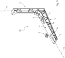
Figure 1 is a perspective view of a first embodiment of a support bracket which is constructed according to the invention, -
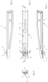
Figure 2 is a side view of a detail of the bracket ofFigure 1 , -
Figure 3 is a plan view of the detail of the bracket ofFigure 2 , -
Figure 4 is a cross-section along the line IV-IV ofFigure 3 , -
Figure 5 is a cross-section along the line V-V ofFigure 3 , -
Figures 6 and 7 are perspective views, drawn to an enlarged scale, of an additional detail of the bracket of the preceding Figures, -
Figure 8 is a side view of the detail shown inFigures 6 and 7 , -
Figure 9 is a perspective view of a second embodiment of a bracket which is constructed according to the invention, -
Figures 10 and 11 are perspective views of additional embodiments of a bracket which is constructed according to the invention. - Initially with reference to
Figures 1 to 8 , there is generally designated 1 a first embodiment of a support bracket for equipment items, typically air-conditioning plant units (not illustrated), which is constructed according to the present invention. - Normally, there is provision for a pair of
brackets 1 to be provided in a parallel and spaced-apart relationship with suitable relative spacing in order to define the support and fixing surfaces of the equipment, even if different configurations are possible. - The
bracket 1 comprises a first and a second portion which are designated 2 and 3, respectively, and which are configured to be secured to each other at converging ends thereof in order to assume a square configuration which substantially extends in an L-like manner and which is suitable for performing the support function for the equipment. - The securing system between the
bracket portions Figure 1 . Other blocking systems of the bracket portions or articulation portions with blocking in the extended L-shaped position are possible. The inventive concept forming the basis of the invention is further also applicable to support brackets in which the first portion andsecond portion first bracket portion 2 therefore forms the vertical upright of the bracket which is provided for anchoring it, either directly to the wall or by means of coupling to a guiding cross-member which is in turn fixed to the wall, while thesecond portion 3 forms the horizontal arm of the bracket which is provided for supporting and fixing the equipment on the bracket. - Each of the
bracket portions bracket portion 2 and X for thebracket portion 3, thebracket portion 3 extending between oppositelongitudinal ends - There is defined on the
second bracket portion 3 asurface portion 4 which extends between theends - The
bracket 1 is advantageously made from metal material and is U-shaped in cross-section, wherein thesurface portion 4 forms the upper connection wall of the opposite lateral sides which are designated 4a, 4b. - In order to anchor the equipment item to the bracket, the
surface portion 4 is further provided with at least one respective through-opening 5 which is in the form of an elongate slot parallel with the direction X for slidingly engaging with at least one screw type locking member which is generally designated 6 and which is provided to lock the equipment item on the corresponding bracket. - In a preferred form, which is shown in the Figures of this embodiment, the
surface portion 4 is provided with twoopenings 5 which are aligned with each other with predetermined spacing in the X direction, each opening being able to be engaged with a correspondingscrew type member 6. As a result of their structural identity, only one of theopenings 5 will be described in detail below, it therefore being understood that this description may refer equally well to each of the openings provided. - In each
opening 5, the elongate slot-like shape which delimits the opening has, at one of the opposite ends of the slot, a widenedportion 5a of the opening, the extent of which is such as to allow ahead 8 of thescrew type member 6 to be inserted and to extend through theopening 5. In an additional embodiment, in accordance with specific requirements, there may be provision for a respective widenedportion 5a of the opening to be present in each of the longitudinal ends of theopening 5. - In greater detail, the
screw type member 6 is provided with an externally threadedshank 9 which extends from thehead 8 and which is provided to be engaged in a screwing manner, for example, by a locking nut (not illustrated) which is suitable for ensuring the locking of the equipment item against the support bracket. - According to a main feature of the invention, the
screw type member 6 comprises in the region of the head 8 a pair ofopposite seats - In other words, the
head 8 of the screw type member is retained in sliding engagement on thesurface portion 4 of the bracket, along the slotted extent of the opening. - The
seats Figure 8 as the plane which contains the main axis Z of the screw type member and which is arranged perpendicularly to the plane of the Figure. - In greater detail, each
seat third surface 13. There remains received between thesurfaces surface portion 4 of the bracket, which is further abutted by thecorresponding surface 13. The spacing between theopposite surfaces surface portion 4 is received therebetween with a limited amount of connection play which allows sliding engagement with relative sliding between the connected surfaces. Eachsurface 13 has a planar configuration and the spacing between the pair of thesurfaces 13 is selected so that thehead 8 is slidingly guided with substantially translational movement along theslotted opening 5 without any substantial possibility of rotation of thescrew type member 6 about the individual axis Z. - The
head 8 of the screw type member is advantageously formed as a co-moulded member on the threadedshank 9. In one embodiment, there may be provision for using a screw, the threadedshank 9 of which extends from a metal head, of conventional shape, for example, with a polygonal profile, and on which thehead 8 made of plastics material is co-moulded. - In the embodiment shown in
Figure 1 , thehead 9 of the screw type member has amain member 14 which has an approximately parallelepipedal formation and on which therespective surfaces 11 are defined. Thesurfaces 12 are defined on a plate-like portion 15 of the head which is arranged between themember 14 and theshank 9. - During operation, the
screw type member 6 is connected to the bracket by inserting thehead 8 from above inside the widenedportion 5a of the slottedopening 5. Once the head is inserted, it is moved in sliding engagement along the slot (with thesurface portion 4 received in and abutted by theseats opening 5 at the bottom. The head of the screw is therefore retained in position inside the slotted opening with freedom to move in a sliding manner in translation along the slotted opening but without being able either to be removed from the slot or rotating about the individual axis Z. In this manner, as long as the screw type member is not locked in a screwed manner with the locking nut, in order to lock the equipment item on the support bracket, the screw type member remains retained inside the slotted opening with the threaded shank projecting at the upper side and the head retained in sliding engagement with thesurface portion 4 of the bracket. Once the position preselected by the fitter for locking the equipment item has been reached, the locking nut is screwed on the threaded shank in order to complete the locking action. In this step, the manoeuvring wrench is applied only to the nut because the head is blocked in terms of rotation about the individual axis Z as a result of the effect of the connection with respect to thesurface portion 4 of the bracket. -
Figure 9 shows a second embodiment of the invention, in which similar details to those of the preceding embodiment are denoted with the same reference numerals. - This embodiment differs from the preceding one mainly in that the support bracket, which is generally designated 20, is made from plastics material, for example, with moulding technology, wherein the two
bracket portions - The
surface portion 4 is formed with a transverse thickness which is suitable for connection to the head of thescrew type member 6, the formation of which reflects the one described in relation to the preceding embodiment. -
Figure 10 shows a further variant, designated 30, of the support bracket which is provided for using screw type locking members as described in the preceding embodiments. According to this variant, thebracket portions portion 3 is provided with a tubular end seat, inside which thebracket portion 2 is retained. Thebracket portions -
Figure 11 shows a further variant, designated 40, of the bracket in which the twoportions Figures 10 and 11 , thesurface portion 4 of thebracket portion 3 is constructed to have a transverse thickness which is suitable for connection with respect to the head of thescrew type member 6, the formation of which reflects the one described in the preceding embodiments. - The invention thereby achieves the objectives set out, affording the advantages set out with respect to the known solutions.
- A main advantage is that, according to the invention, the screw type locking members can be retained in position in the slotted through-openings of the brackets until the time when the respective locking nuts are screwed without requiring any intervention by the fitter, preventing the screws from falling out of the slot-like openings, thereby making the locking operations easier for the fitter.
- Another advantage is that, in the brackets according to the invention, the screw type locking members are slidingly retained in the slotted openings, before the locking, without the screw being able to rotate freely about the individual axis, making the locking operations of the locking nuts against the brackets easier for the fitter.
- Another advantage is that, in the support bracket according to the invention, the screw type members can be positioned on the bracket without any risk of leaving or falling out, already in a preliminary step with respect to being fixed to the wall, facilitating and making more convenient the subsequent operations of anchoring the equipment item, with a substantial improvement of the steps of installation, in particular for wall-mounted installation of the equipment items at significant heights.
Claims (8)
- A support bracket for equipment, in particular units for air-conditioning plants, comprising a first bracket portion and a second bracket portion (2, 3) which are arranged for anchoring the bracket to a wall and for supporting and fixing the equipment to the bracket, respectively, the first and second bracket portions (2, 3) being able to be secured to each other in an operating condition, in which they assume an L-shaped configuration suitable for supporting the equipment, there being defined on the second bracket portion (3) a surface portion (4) which is intended for the supporting contact of the equipment, the surface portion (4) being provided with at least one through-opening (5) which is in the form of an elongate slot, for engaging in a sliding manner with at least one respective screw type member (6) which is intended to anchor the equipment on the corresponding bracket, the screw type member (6) comprising a head (8) and a threaded shank (9) which extends from the head, characterised in that the screw type member (6) comprises, in the region of the head (8), a pair of opposite seats (10a, 10b), each seat being configured to be connected, with sliding engagement, to a corresponding peripheral edge of the through-opening (5) so that the screw type member (6) is retained in a manner slidingly guided along the opening (5), thereby preventing the screw type member (6) from falling out of the opening.
- A support bracket according to claim 1, wherein the through-opening (5) has an elongate formation in a main longitudinal direction and has a widened portion (5a) in the region of at least one of the opposite longitudinal ends thereof with such an extent as to allow the insertion of the head (8) of the screw type member (6) through the widened portion (5a) of the opening and the sliding engagement of the head (8) with the surface portion of the bracket along the slotted extent of the opening (5).
- A support bracket according to claim 1 or 2, wherein each of the seats (10a, 10b) is defined by a first surface and a second surface (11, 12) which are parallel with and spaced apart from each other and which are connected to a third surface (13), the transverse thickness of the surface portion (4) of the bracket being received between the first surface and the second surface (11, 12) and being abutted by the third surface (13).
- A support bracket according to claim 3, wherein the third surface (13) has a planar configuration and the distance between the pair of the third surfaces (13) is selected in such a manner that the head (8) is slidingly guided in terms of translation in the slotted opening (5) without any substantial possibility of rotation about the main axis of the screw type member (6).
- A support bracket according to any one of the preceding claims, wherein the head (8) is made from plastics material co-moulded on the threaded shank (9).
- A support bracket according to claim 3 or 4, wherein the first surface (11) of each seat is defined in a main member (14) of the head (8) and the second surface (12) is defined in a plate-like portion (15) of the head (8) arranged between the main member (14) and the threaded shank (9).
- A support bracket according to any one of the preceding claims, wherein there are provided a pair of the slotted through-openings (5) which are aligned at a predetermined distance in the longitudinal development direction.
- A support bracket according to any one of the preceding claims, wherein the second bracket portion (3) is made from metal material or plastics material.
Applications Claiming Priority (1)
| Application Number | Priority Date | Filing Date | Title |
|---|---|---|---|
| IT102021000027443A IT202100027443A1 (en) | 2021-10-26 | 2021-10-26 | Support bracket for equipment, in particular air conditioning units |
Publications (3)
| Publication Number | Publication Date |
|---|---|
| EP4174398A1 true EP4174398A1 (en) | 2023-05-03 |
| EP4174398C0 EP4174398C0 (en) | 2025-08-27 |
| EP4174398B1 EP4174398B1 (en) | 2025-08-27 |
Family
ID=79269983
Family Applications (1)
| Application Number | Title | Priority Date | Filing Date |
|---|---|---|---|
| EP22203375.5A Active EP4174398B1 (en) | 2021-10-26 | 2022-10-24 | A support bracket for equipment, in particular units for air-conditioning plants |
Country Status (2)
| Country | Link |
|---|---|
| EP (1) | EP4174398B1 (en) |
| IT (1) | IT202100027443A1 (en) |
Citations (4)
| Publication number | Priority date | Publication date | Assignee | Title |
|---|---|---|---|---|
| JP2006308243A (en) * | 2005-04-28 | 2006-11-09 | Daikin Ind Ltd | Wall mount for outdoor unit for air conditioner and method for installing outdoor unit for air conditioner using the same |
| EP2369248A2 (en) * | 2010-03-22 | 2011-09-28 | Cappellari 80 S.r.L. | Supporting bracketed device for apparatuses |
| US20160123625A1 (en) * | 2014-10-30 | 2016-05-05 | William J. Crowley | Wall mount bracket for outdoor equipment |
| EP3792567A1 (en) * | 2019-09-16 | 2021-03-17 | Rodigas S.r.l. | Bracket for walls |
-
2021
- 2021-10-26 IT IT102021000027443A patent/IT202100027443A1/en unknown
-
2022
- 2022-10-24 EP EP22203375.5A patent/EP4174398B1/en active Active
Patent Citations (4)
| Publication number | Priority date | Publication date | Assignee | Title |
|---|---|---|---|---|
| JP2006308243A (en) * | 2005-04-28 | 2006-11-09 | Daikin Ind Ltd | Wall mount for outdoor unit for air conditioner and method for installing outdoor unit for air conditioner using the same |
| EP2369248A2 (en) * | 2010-03-22 | 2011-09-28 | Cappellari 80 S.r.L. | Supporting bracketed device for apparatuses |
| US20160123625A1 (en) * | 2014-10-30 | 2016-05-05 | William J. Crowley | Wall mount bracket for outdoor equipment |
| EP3792567A1 (en) * | 2019-09-16 | 2021-03-17 | Rodigas S.r.l. | Bracket for walls |
Also Published As
| Publication number | Publication date |
|---|---|
| EP4174398C0 (en) | 2025-08-27 |
| IT202100027443A1 (en) | 2023-04-26 |
| EP4174398B1 (en) | 2025-08-27 |
Similar Documents
| Publication | Publication Date | Title |
|---|---|---|
| JP5745430B2 (en) | Mounting clip | |
| US5667181A (en) | Hanger | |
| US5546716A (en) | Joist bridge | |
| US20030037494A1 (en) | Wall stud spacer system with spacer retainers | |
| US20200190814A1 (en) | Support bracket apparatus | |
| US7819371B2 (en) | Universal suspended anchor system | |
| US20170342736A1 (en) | Track system for supporting wall studs | |
| EP2194205B1 (en) | Improved removable bracket for connecting a structural element to a supporting surface | |
| KR102230212B1 (en) | Metal panel roof with compatibility and slide movement and vertical adjustment | |
| EP2309072B1 (en) | Fixing system for ventilated walls | |
| US7603814B1 (en) | Decking system hanger | |
| EP4174399B1 (en) | A support bracket for equipment, in particular for air-conditioning units | |
| US3356402A (en) | Framing system for a suspended ceiling | |
| EP4174398B1 (en) | A support bracket for equipment, in particular units for air-conditioning plants | |
| JP4119856B2 (en) | Outdoor floor forming deck | |
| AU2022345473A2 (en) | Device for a ventilated facade | |
| EP0605988A2 (en) | A carrier construction | |
| KR20230039804A (en) | Reinforcement for dry walls | |
| EP4123853A1 (en) | Support structure for profiles supporting cable carrier systems in industrial ducts | |
| EP3851761B1 (en) | A support device for equipment, in particular air-conditioning installation units | |
| WO2024007452A1 (en) | Fixing device, fixing device mounting method, and wall construction method | |
| KR102133937B1 (en) | Duct hanger | |
| KR102910269B1 (en) | Frame assembly and construction method of the same | |
| KR102941326B1 (en) | Method for constructing slab formwork in narrow spaces using horizontal member connecting device of multi-support for construction | |
| EP4249701B1 (en) | Supporting structure and installation method for making a ventilated facade |
Legal Events
| Date | Code | Title | Description |
|---|---|---|---|
| PUAI | Public reference made under article 153(3) epc to a published international application that has entered the european phase |
Free format text: ORIGINAL CODE: 0009012 |
|
| STAA | Information on the status of an ep patent application or granted ep patent |
Free format text: STATUS: THE APPLICATION HAS BEEN PUBLISHED |
|
| AK | Designated contracting states |
Kind code of ref document: A1 Designated state(s): AL AT BE BG CH CY CZ DE DK EE ES FI FR GB GR HR HU IE IS IT LI LT LU LV MC ME MK MT NL NO PL PT RO RS SE SI SK SM TR |
|
| STAA | Information on the status of an ep patent application or granted ep patent |
Free format text: STATUS: REQUEST FOR EXAMINATION WAS MADE |
|
| 17P | Request for examination filed |
Effective date: 20231027 |
|
| RBV | Designated contracting states (corrected) |
Designated state(s): AL AT BE BG CH CY CZ DE DK EE ES FI FR GB GR HR HU IE IS IT LI LT LU LV MC ME MK MT NL NO PL PT RO RS SE SI SK SM TR |
|
| GRAP | Despatch of communication of intention to grant a patent |
Free format text: ORIGINAL CODE: EPIDOSNIGR1 |
|
| STAA | Information on the status of an ep patent application or granted ep patent |
Free format text: STATUS: GRANT OF PATENT IS INTENDED |
|
| RIC1 | Information provided on ipc code assigned before grant |
Ipc: F16L 3/22 20060101ALI20250314BHEP Ipc: F16M 13/02 20060101ALI20250314BHEP Ipc: F24F 13/32 20060101AFI20250314BHEP |
|
| INTG | Intention to grant announced |
Effective date: 20250402 |
|
| GRAS | Grant fee paid |
Free format text: ORIGINAL CODE: EPIDOSNIGR3 |
|
| GRAA | (expected) grant |
Free format text: ORIGINAL CODE: 0009210 |
|
| STAA | Information on the status of an ep patent application or granted ep patent |
Free format text: STATUS: THE PATENT HAS BEEN GRANTED |
|
| RAP1 | Party data changed (applicant data changed or rights of an application transferred) |
Owner name: ASPEN PUMPS ITALIA S.R.L. |
|
| AK | Designated contracting states |
Kind code of ref document: B1 Designated state(s): AL AT BE BG CH CY CZ DE DK EE ES FI FR GB GR HR HU IE IS IT LI LT LU LV MC ME MK MT NL NO PL PT RO RS SE SI SK SM TR |
|
| REG | Reference to a national code |
Ref country code: CH Ref legal event code: EP |
|
| REG | Reference to a national code |
Ref country code: DE Ref legal event code: R096 Ref document number: 602022020144 Country of ref document: DE |
|
| REG | Reference to a national code |
Ref country code: IE Ref legal event code: FG4D |
|
| U01 | Request for unitary effect filed |
Effective date: 20250915 |
|
| U07 | Unitary effect registered |
Designated state(s): AT BE BG DE DK EE FI FR IT LT LU LV MT NL PT RO SE SI Effective date: 20250922 |
|
| U20 | Renewal fee for the european patent with unitary effect paid |
Year of fee payment: 4 Effective date: 20251014 |
|
| PG25 | Lapsed in a contracting state [announced via postgrant information from national office to epo] |
Ref country code: IS Free format text: LAPSE BECAUSE OF FAILURE TO SUBMIT A TRANSLATION OF THE DESCRIPTION OR TO PAY THE FEE WITHIN THE PRESCRIBED TIME-LIMIT Effective date: 20251227 |
|
| PG25 | Lapsed in a contracting state [announced via postgrant information from national office to epo] |
Ref country code: NO Free format text: LAPSE BECAUSE OF FAILURE TO SUBMIT A TRANSLATION OF THE DESCRIPTION OR TO PAY THE FEE WITHIN THE PRESCRIBED TIME-LIMIT Effective date: 20251127 |
|
| PG25 | Lapsed in a contracting state [announced via postgrant information from national office to epo] |
Ref country code: HR Free format text: LAPSE BECAUSE OF FAILURE TO SUBMIT A TRANSLATION OF THE DESCRIPTION OR TO PAY THE FEE WITHIN THE PRESCRIBED TIME-LIMIT Effective date: 20250827 |
|
| PG25 | Lapsed in a contracting state [announced via postgrant information from national office to epo] |
Ref country code: GR Free format text: LAPSE BECAUSE OF FAILURE TO SUBMIT A TRANSLATION OF THE DESCRIPTION OR TO PAY THE FEE WITHIN THE PRESCRIBED TIME-LIMIT Effective date: 20251128 |
|
| PG25 | Lapsed in a contracting state [announced via postgrant information from national office to epo] |
Ref country code: PL Free format text: LAPSE BECAUSE OF FAILURE TO SUBMIT A TRANSLATION OF THE DESCRIPTION OR TO PAY THE FEE WITHIN THE PRESCRIBED TIME-LIMIT Effective date: 20250827 |
|
| PG25 | Lapsed in a contracting state [announced via postgrant information from national office to epo] |
Ref country code: RS Free format text: LAPSE BECAUSE OF FAILURE TO SUBMIT A TRANSLATION OF THE DESCRIPTION OR TO PAY THE FEE WITHIN THE PRESCRIBED TIME-LIMIT Effective date: 20251127 |
|
| PG25 | Lapsed in a contracting state [announced via postgrant information from national office to epo] |
Ref country code: ES Free format text: LAPSE BECAUSE OF FAILURE TO SUBMIT A TRANSLATION OF THE DESCRIPTION OR TO PAY THE FEE WITHIN THE PRESCRIBED TIME-LIMIT Effective date: 20250827 |
|
| PG25 | Lapsed in a contracting state [announced via postgrant information from national office to epo] |
Ref country code: SM Free format text: LAPSE BECAUSE OF FAILURE TO SUBMIT A TRANSLATION OF THE DESCRIPTION OR TO PAY THE FEE WITHIN THE PRESCRIBED TIME-LIMIT Effective date: 20250827 |
|
| PG25 | Lapsed in a contracting state [announced via postgrant information from national office to epo] |
Ref country code: CZ Free format text: LAPSE BECAUSE OF FAILURE TO SUBMIT A TRANSLATION OF THE DESCRIPTION OR TO PAY THE FEE WITHIN THE PRESCRIBED TIME-LIMIT Effective date: 20250827 |
|
| PG25 | Lapsed in a contracting state [announced via postgrant information from national office to epo] |
Ref country code: SK Free format text: LAPSE BECAUSE OF FAILURE TO SUBMIT A TRANSLATION OF THE DESCRIPTION OR TO PAY THE FEE WITHIN THE PRESCRIBED TIME-LIMIT Effective date: 20250827 |
|
| REG | Reference to a national code |
Ref country code: CH Ref legal event code: H13 Free format text: ST27 STATUS EVENT CODE: U-0-0-H10-H13 (AS PROVIDED BY THE NATIONAL OFFICE) Effective date: 20260527 |
|
| PG25 | Lapsed in a contracting state [announced via postgrant information from national office to epo] |
Ref country code: MC Free format text: LAPSE BECAUSE OF FAILURE TO SUBMIT A TRANSLATION OF THE DESCRIPTION OR TO PAY THE FEE WITHIN THE PRESCRIBED TIME-LIMIT Effective date: 20250827 |
|
| PLBE | No opposition filed within time limit |
Free format text: ORIGINAL CODE: 0009261 |
|
| STAA | Information on the status of an ep patent application or granted ep patent |
Free format text: STATUS: NO OPPOSITION FILED WITHIN TIME LIMIT |
|
| REG | Reference to a national code |
Ref country code: CH Ref legal event code: L10 Free format text: ST27 STATUS EVENT CODE: U-0-0-L10-L00 (AS PROVIDED BY THE NATIONAL OFFICE) Effective date: 20260708 |
|
| PG25 | Lapsed in a contracting state [announced via postgrant information from national office to epo] |
Ref country code: CH Free format text: LAPSE BECAUSE OF NON-PAYMENT OF DUE FEES Effective date: 20251031 |
|
| 26N | No opposition filed |
Effective date: 20260528 |