EP4174386A1 - Cooking appliance - Google Patents
Cooking appliance Download PDFInfo
- Publication number
- EP4174386A1 EP4174386A1 EP22201823.6A EP22201823A EP4174386A1 EP 4174386 A1 EP4174386 A1 EP 4174386A1 EP 22201823 A EP22201823 A EP 22201823A EP 4174386 A1 EP4174386 A1 EP 4174386A1
- Authority
- EP
- European Patent Office
- Prior art keywords
- door
- air
- air guide
- cooking appliance
- disposed
- Prior art date
- Legal status (The legal status is an assumption and is not a legal conclusion. Google has not performed a legal analysis and makes no representation as to the accuracy of the status listed.)
- Granted
Links
Images




Classifications
-
- F—MECHANICAL ENGINEERING; LIGHTING; HEATING; WEAPONS; BLASTING
- F24—HEATING; RANGES; VENTILATING
- F24C—DOMESTIC STOVES OR RANGES ; DETAILS OF DOMESTIC STOVES OR RANGES, OF GENERAL APPLICATION
- F24C15/00—Details
- F24C15/02—Doors specially adapted for stoves or ranges
-
- F—MECHANICAL ENGINEERING; LIGHTING; HEATING; WEAPONS; BLASTING
- F24—HEATING; RANGES; VENTILATING
- F24C—DOMESTIC STOVES OR RANGES ; DETAILS OF DOMESTIC STOVES OR RANGES, OF GENERAL APPLICATION
- F24C15/00—Details
- F24C15/006—Arrangements for circulation of cooling air
-
- F—MECHANICAL ENGINEERING; LIGHTING; HEATING; WEAPONS; BLASTING
- F24—HEATING; RANGES; VENTILATING
- F24C—DOMESTIC STOVES OR RANGES ; DETAILS OF DOMESTIC STOVES OR RANGES, OF GENERAL APPLICATION
- F24C15/00—Details
- F24C15/32—Arrangements of ducts for hot gases, e.g. in or around baking ovens
- F24C15/322—Arrangements of ducts for hot gases, e.g. in or around baking ovens with forced circulation
-
- H—ELECTRICITY
- H05—ELECTRIC TECHNIQUES NOT OTHERWISE PROVIDED FOR
- H05B—ELECTRIC HEATING; ELECTRIC LIGHT SOURCES NOT OTHERWISE PROVIDED FOR; CIRCUIT ARRANGEMENTS FOR ELECTRIC LIGHT SOURCES, IN GENERAL
- H05B6/00—Heating by electric, magnetic or electromagnetic fields
- H05B6/64—Heating using microwaves
- H05B6/6402—Aspects relating to the microwave cavity
-
- H—ELECTRICITY
- H05—ELECTRIC TECHNIQUES NOT OTHERWISE PROVIDED FOR
- H05B—ELECTRIC HEATING; ELECTRIC LIGHT SOURCES NOT OTHERWISE PROVIDED FOR; CIRCUIT ARRANGEMENTS FOR ELECTRIC LIGHT SOURCES, IN GENERAL
- H05B6/00—Heating by electric, magnetic or electromagnetic fields
- H05B6/64—Heating using microwaves
- H05B6/6414—Aspects relating to the door of the microwave heating apparatus
-
- H—ELECTRICITY
- H05—ELECTRIC TECHNIQUES NOT OTHERWISE PROVIDED FOR
- H05B—ELECTRIC HEATING; ELECTRIC LIGHT SOURCES NOT OTHERWISE PROVIDED FOR; CIRCUIT ARRANGEMENTS FOR ELECTRIC LIGHT SOURCES, IN GENERAL
- H05B6/00—Heating by electric, magnetic or electromagnetic fields
- H05B6/64—Heating using microwaves
- H05B6/642—Cooling of the microwave components and related air circulation systems
-
- H—ELECTRICITY
- H05—ELECTRIC TECHNIQUES NOT OTHERWISE PROVIDED FOR
- H05B—ELECTRIC HEATING; ELECTRIC LIGHT SOURCES NOT OTHERWISE PROVIDED FOR; CIRCUIT ARRANGEMENTS FOR ELECTRIC LIGHT SOURCES, IN GENERAL
- H05B6/00—Heating by electric, magnetic or electromagnetic fields
- H05B6/64—Heating using microwaves
- H05B6/6435—Aspects relating to the user interface of the microwave heating apparatus
-
- H—ELECTRICITY
- H05—ELECTRIC TECHNIQUES NOT OTHERWISE PROVIDED FOR
- H05B—ELECTRIC HEATING; ELECTRIC LIGHT SOURCES NOT OTHERWISE PROVIDED FOR; CIRCUIT ARRANGEMENTS FOR ELECTRIC LIGHT SOURCES, IN GENERAL
- H05B6/00—Heating by electric, magnetic or electromagnetic fields
- H05B6/64—Heating using microwaves
- H05B6/76—Prevention of microwave leakage, e.g. door sealings
Definitions
- the present invention relates to a cooking appliance, and more specifically, to a cooking appliance installed above a heating cooking device.
- a cooking appliance is a home appliance that is used for cooking food using microwaves and/or heater heat, which are type(s) of electromagnetic waves.
- the cooking appliance may generally include a main body forming a cavity therein, which is an accommodation space in which food is placed and cooked, and one or more doors that opens and closes the cavity.
- the cooking appliance may be disposed at a location adjacent to a heating cooking device, for example, a heating-type oven, a gas range, etc. Specifically, the cooking appliance may be disposed above the heating cooking device.
- the cooking appliance When the cooking appliance is disposed above the heating cooking device, a user can conveniently cook food by reducing his/her movement in an environment where the cooking appliance and the heating cooking device are adjacent to each other.
- heat, oil mist, etc. generated from the heating cooking device can be discharged to the outside using the cooking appliance as a hood.
- the heat, oil mist, etc. generated from the heating cooking device disposed below the cooking appliance may adversely affect an operation of the cooking appliance.
- a display unit may be mounted on a front surface of a door provided in the cooking appliance in order to provide various types of information to the user.
- the user may receive information on the display unit for a cooking state of the cooked food.
- the display unit may be connected to another home appliance and may serve as a hub of the home appliance. Then, information other than cooking of food may be obtained through the display unit.
- the user may also input commands into the display unit including a touch screen by using a touch input method. The commands might be required for cooking and/or other various commands for controlling other connected devices or input messages for being sent.
- the heat, oil mist, etc. generated from the heating cooking device may penetrate into the display unit and other parts mounted on the door.
- a cooking appliance having a display unit provided on a front surface thereof to provide various types of information to the user.
- a further object is to provide a cooking appliance having a display unit provided on a door of the cooking appliance using microwaves.
- a further object is to provide a cooking appliance having a structure being capable of suppressing heat, oil mist, from penetrating into a door.
- a further object is to provide a cooking appliance having a structure being capable of suppressing or preventing a display unit from being contaminated by oil mist.
- a further object is to provide a cooking appliance having a cooling structure of a display module attached to a front surface of a door.
- a further object is to provide a cooking appliance having a structure being capable of suppressing or preventing heat, oil mist, etc. from penetrating into a door by forming an air curtain outside the door.
- a further object is to provide a cooking appliance having a door equipped with a display unit on a front surface thereof and formed with a cooling structure for cooling the display unit and a microwave shielding structure for preventing microwave leakage.
- a further object is to provide a cooking appliance having a structure that suppresses air from leaking through a gap at an edge of an air guide and to improve the cooling of the components inside the door.
- a cooking appliance comprising a main body formed with a cavity, and a door for opening and closing the cavity.
- the door includes a display module disposed on a front of the door; a cooling flow path unit disposed behind the display module, and having a flow path through which air for cooling flows formed therein.
- a cooking appliance comprising a main body formed with a cavity, and a door for opening and closing the cavity.
- the door includes a display module disposed on a front of the door; and a cooling flow path unit disposed behind the display module and having a flow path through which air for cooling flows formed therein.
- the cooling flow path unit may include an air guide configured to guide the flow of the air introduced into the door; and a blowing device mounted on the air guide.
- the air guide may include at least one inlet through which external air is introduced.
- the display module may include a display unit on which videos or images are displayed
- the display module may include an outer panel disposed behind the display unit, and on which the display unit is mounted.
- the cooling flow path unit may include an inner panel disposed behind the outer panel and mounted on the outer panel.
- the cooling flow path unit may include an air guide disposed between the outer panel and the inner panel and coupled to the inner panel.
- the cooking appliance may include a main body formed with a cavity, and a door for opening and closing the cavity.
- the door may include a display module disposed in front of the door, a cooling flow path unit disposed behind the display module and a shielding unit disposed behind the cooling flow path unit.
- the cooling flow path unit may disposed behind the display module, and may having a flow path through which air for cooling flows formed therein.
- the shielding unit may be disposed behind the cooling flow path unit, and may be configured to shield electromagnetic waves generated from the main body.
- the air flowing through the cooling flow path unit may be branched inside of the cooling flow path unit to be discharged to the top and bottom of the display module.
- the external air when the blowing fan rotates, the external air may flow into the door through an inlet of the air guide, and may flow to be discharged to the outside through a first outlet and a second outlet.
- the air forcibly flowing by the blowing fan may specifically have the following flow path.
- the air may flow into the door from the first aperture of the outer panel and the inlet provided at the location corresponding thereto.
- the air flowing into the door may flow in a downward direction of the door to flow into the blowing fan.
- the air may pass through the blowing fan in the front-rear direction of the door. At this time, the air may pass through the mounting hole of the air guide while passing through the blowing fan.
- the flow direction of the air may be changed from the up-down direction into the front-rear direction of the door at the blowing fan.
- the air passing through the mounting hole may be branched in front of the air guide in the up-down direction.
- a part of the branched air may flow in an upward direction of the door to be discharged through the first outlet.
- the other part of the branched air may flow in the downward direction of the door to be discharged to the second outlet.
- the air branched on the first outlet and the second outlet may surround the entire door.
- the branched air may surround the front portion of the door.
- this structure can allow the air discharged through the first outlet and the second outlet to form the air curtain on the door, thereby effectively suppressing the heat and oil mist generated from the heating cooling device disposed below the cooking appliance from permeating into the door.
- the cooking appliance may include a main body formed with a cavity, and a door for opening and closing the cavity.
- the door may include a display unit configured to display videos or images, an outer panel disposed behind the display unit and on which the display unit is mounted, an inner panel disposed behind the outer panel, and mounted on the outer panel, an air guide disposed between the outer panel and the inner panel, and coupled to the inner panel, and a blowing device mounted on the air guide.
- the inner panel may include a blocking protrusion protruding from a portion corresponding to an edge of the air guide toward the air guide, and engaged with the air guide to block air from leaking through a gap between the air guide and the inner panel.
- the blocking protrusion may include a first blocking portion formed on a lower portion of the inner panel, and having a longitudinal direction disposed in both side directions of the inner panel, and a pair of second blocking portions provided to be connected to ends of both sides of the first blocking portion, respectively, and having a longitudinal direction disposed in an up-down direction of the inner panel.
- the air guide may include an engagement groove portion provided on an edge in a shape corresponding to the blocking protrusion, and engaged with the blocking protrusion to block air from leaking through the gap between the air guide and the inner panel.
- the engagement groove portion may include a first engagement portion disposed at a location corresponding to the first blocking portion, and having a longitudinal direction disposed in both side directions of the air guide.
- the engagement groove portion may include a second engagement portion disposed at a location corresponding to the second blocking portion, provided as a pair, and having a longitudinal direction disposed in an up-down direction of the air guide.
- the engagement groove portion may include a first bent portion bent from an end of the inner panel, a second bent portion bent from the first bent portion, and provided so that at least a part thereof is in contact with a tip of the blocking protrusion, and a third bent portion bent from the second bent portion.
- the blocking protrusion may include a hook formed to protrude from the second blocking portion.
- the engagement groove portion may include a fitting hole formed in the second engagement portion.
- the fitting hole may be provided at a location corresponding to the hook, and may having the hook fitted therein.
- the hooks may be formed on both sides of the pair of second blocking portions, respectively.
- the fitting holes may be formed in both sides of the pair of second engagement portions, respectively.
- the second engagement portion may include an elastically deformable portion formed on the edge of the air guide so that at least a part thereof is separated from a remaining portion of the second engagement portion, formed with the fitting hole, and provided so that at least a part thereof is elastically deformed when the hook is fitted into the fitting hole.
- a plurality of hooks may be provided, and each of the hooks may be disposed to be spaced apart from each other in a longitudinal direction of the second blocking portion, and a plurality of fitting holes may be provided, and each of the fitting holes may be spaced apart from each other in a longitudinal direction of the second engagement portion and disposed at a location corresponding to each of the hooks.
- the outer panel may include a first outlet disposed on an upper portion, and having the air flowing by the blowing device discharged to the outside therethrough.
- the outer panel may include a second outlet disposed on a lower portion, and having the air flowing by the blowing device discharged to the outside therethrough.
- the air guide may include at least one inlet disposed on an upper portion, and having external air introduced therein, and a mounting hole formed on a lower portion of the inlet, and mounted with the blowing device.
- the blowing device may include a casing disposed in the mounting hole.
- the blowing device may include a blowing fan rotatably mounted in the casing, and flowing air from the rear to the front of the air guide.
- the air forcibly flowing by the blowing fan may be introduced from the inlet to flow in a downward direction of the door to flow into the blowing fan.
- the air forcibly flowing by the blowing fan may pass through the blowing fan in a front-rear direction of the door.
- the air forcibly flowing by the blowing fan may be branched in front of the air guide in an up-down direction, a part of which may flow in an upward direction of the door to be discharged to the first outlet, and the other part of which may flow in a downward direction of the door to be discharged to the second outlet.
- the door may further include a baffle disposed in front of the display unit, surrounding an edge of the display unit, and coupled to the outer panel to mount the display unit on the outer panel.
- the door may further include a front cover disposed in front of the baffle, and provided to surround an edge of the baffle.
- the door may further include a plate disposed behind the inner panel, coupled to the inner panel, and having one side rotatably coupled to the main body.
- the door may further include at least one camera.
- the door may further include a first camera mounted on a lower portion of the outer panel to capture a state of a lower portion of the door, a second camera disposed on an upper portion of the door, mounted by passing through the baffle and the front cover, and configured to capture the front of the door, and a third camera mounted on the plate, disposed to face the cavity, and configured to capture the cavity.
- the door may further include a human detection unit disposed on the upper portion of the door.
- the human detection unit may be mounted by passing through the baffle and the front cover, and/or may be disposed at a location spaced apart from the second camera, and/or may be configured to detect the presence of a user in front of the cooking appliance.
- the display module is provided on the front of the door, the user can know the cooking situation in the cooking appliance through the display module.
- the display module can serve as the hub of another home appliance to provide various types of information to the user, thereby enhancing the user's convenience.
- the airflow discharged to the outside of the door through the first outlet and the second outlet can form an air curtain, so that the heat and oil mist rising from the heating cooking device disposed below the cooking appliance can be effectively blocked by the air curtain.
- the air flowing inside the door can be discharged through the first outlet to cool the entire front surface of the display unit.
- the air flowing inside the door can effectively cool the heat-generating parts mounted on the rear surface of the display unit and inside the door.
- a door having all of the display structure, the cooling structure, and the shielding structure of the electromagnetic waves can be formed.
- the display structure, the cooling structure, and the shielding structure can be coupled to one another to slimly form the door as a whole. Accordingly, it is possible to prevent the thickness of the door from being increased even when all of the display structure, the cooling structure, and the shielding structure are formed on the door.
- the gap at the edge of the air guide can be blocked by the engagement groove portion and the blocking protrusion, thereby effectively suppressing the air forcibly flowing into the door from leaking at the coupling portion between the edge of the air guide and the inner panel.
- the air forcibly flowing into the door can be suppressed from leaking to the outside of the door to flow along the designed flow path. Due to this structure, it is possible to improve the cooling effect and air curtain forming effect of the door by the forcibly flowing air.
- the hook may be formed on the blocking protrusion, and the engagement groove portion may be formed with the fitting hole at the location corresponding to the hook. Accordingly, the air guide and the inner panel can be stably coupled by fitting the fitting hole onto the hook.
- the first bent portion and the third bent portion can double-block the gap that may be formed between the inner panel and the air guide. Accordingly, the air flowing through the space formed by coupling the inner panel and the air guide can be effectively suppressed from leaking through the gap.
- first, second, etc. are used to describe various components, it goes without saying that these components are not limited by these terms. These terms are only used to distinguish one component from other components, and unless otherwise stated, it goes without saying that the first component may also be the second component.
- up-down direction means the up-down direction of the cooking appliance in a state in which the cooking appliance is installed for daily use.
- Left-right direction means a direction perpendicular to the up-down direction
- front-rear direction means a direction perpendicular to both the up-down direction and the left-right direction.
- Bilateral direction or “lateral direction” has the same meaning as the left-right direction, and these terms may be used interchangeably in the present specification.
- FIG. 1 is a perspective view showing a cooking appliance according to one embodiment.
- FIG. 2 is a view showing a state in which a door 20 in FIG. 1 has been opened.
- the cooking appliance according to the embodiment may be disposed at a location spaced apart from a heating cooking device in an up-down direction above a location where the heating cooking device, for example, a heating-type oven, a gas range, etc. is disposed.
- the placement of the cooking appliance can allow a user to conveniently use cooking devices including the cooking appliance.
- the cooking appliance may serve as a hood of the heating cooking device disposed thereunder.
- the cooking appliance may be provided with parts for use as a hood.
- the cooking appliance may cook food using microwaves, and/or heater heat, which are type(s) of electromagnetic waves.
- the cooking appliance may include a main body 10 in which a cavity 11 is formed, and a door 20 that opens and closes the cavity 11.
- the door 20 may be disposed in front of the cavity 11 and rotatably mounted on the main body 10 to open and close the cavity 11.
- a vent hole 13 for discharging the air sucked in a suction unit provided on a lower portion of the main body 10 to the outside may be provided in an upper portion of the main body 10.
- the suction unit may be provided at a lower portion of the main body 10 of the cooking appliance. Accordingly, the cooking appliance may serve as a hood for sucking the air discharged from the heating cooking device disposed thereunder to discharge the air to the outside.
- the main body 10 may further include a front panel 12 provided on an edge of the entrance of the cavity 11, and having one surface disposed to face one surface of a choke member 170 when the door 20 is closed to close the cavity 11.
- the front panel 12 may be provided to surround the edge of the entrance of the cavity 11 and protrude with a predetermined width. Accordingly, when the door 20 is closed, the edge portion of the door 20 and the cavity 11 may overlap each other.
- This structure can allow the front panel 12 to seal the cavity 11 in a state in which the door 20 is closed, thereby suppressing the oil, moisture, oil mist, etc. generated in the process of cooking food placed in the cavity 11 from being discharged to the outside through an inlet of the cavity 11.
- FIG. 3A is a perspective view showing the door 20 of the cooking appliance according to one embodiment.
- FIG. 3B is a view of FIG. 3A from another direction.
- FIG. 4A is a rear view of the door 20.
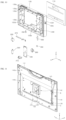
- FIG. 4B is an exploded perspective view showing a part of the door 20 according to one embodiment.
- FIG. 4C is a view of FIG. 4B from another direction.
- the door 20 may include a display module 21, a cooling flow path unit 22, and a shielding unit 23.
- the display module 21 may be disposed in front of the door 20, and the user may see the inside of the cavity 11 of the cooking appliance through the display module 21.
- the cooling flow path unit 22 may be disposed behind the display module 21, and a flow path through which air for cooling flows may be formed therein. The air flowing into the door 20 may flow into the door 20 through the cooling flow path unit 22 to cool the door 20.
- the shielding unit 23 may be disposed behind the cooling flow path unit 22, and may shield electromagnetic waves generated from the main body 10.
- the shielding unit 23 may protect the user by blocking the electromagnetic waves generated in the cavity 11 and propagating to the outside of the cooking appliance.
- the shielding unit 23 may serve to block the electromagnetic waves (microwaves) generated to cook food in the main body 10 from being discharged to the outside of the door 20.
- the cooling flow path unit 22 may be provided to cool electronic components mounted inside the door 20, including a display unit 110 mounted on the display module 21.
- the air for cooling the door 20 may flow inside the cooling flow path unit 22.
- the display unit 110 may be formed in a thin shape and provided so that an area of the display unit 110 occupies most of one surface of the door 20.
- the display unit 110 can be formed to occupy most of the area of the front portion of the door 20, and the placement area of the display unit 110 can be increased, thereby improving user visibility.
- the user may conveniently check various types of information through the display unit 110 provided with a large screen.
- the cooling flow path unit 22 through which the cooling air flows may be separately provided.
- the cooling flow path unit 22 may be disposed behind the display unit 110 so that cooling air flows, and thus the display unit 110 may be effectively cooled by the air flowing through the cooling flow path unit 22.
- a heat-generating part mounted on the display module 21 may be cooled by the air flowing through the cooling flow path unit 22.
- the cooling flow path unit 22 may cool the display module 21 provided with the display unit 110 and other various heat-generating parts.
- the entire display unit 110 may be provided to be exposed to the air flowing through the cooling flow path unit 22.
- the airflow discharged to the outside of the door 20 through the cooling flow path unit 22 may form an air curtain to block heat and oil mist rising from the heating cooking device disposed below the cooking appliance.
- the air flowing through the cooling flow path unit 22 may be branched inside the cooling flow path unit 22 to be discharged to the top and bottom of the display module 21.
- the cooling air is branched inside the cooling flow path unit 22 and discharged to the top and bottom of the display module 21, so that the cooling air can flow while in contact with the entire rear surface of the display unit 110 to effectively cool the display unit 110.
- the cooling air is discharged to each of the top and bottom of the display module 21 to effectively form the air curtain around the display and the door 20, so that the heat and oil mist rising from the heating cooking device disposed below the cooking appliance can be effectively blocked by the air curtain.
- the display module 21 may be provided with the display unit 110, a camera, and other electronic parts, and the cooling flow path unit 22 may be provided with electronic parts such as a blowing device 150 operated by a motor. Accordingly, the shielding unit 23 configured to shield the electromagnetic waves generated from the main body may be provided behind the cooling flow path unit 22 in order to protect the user and the electronic parts from electromagnetic waves.
- the display unit 110 and various electronic parts may be disposed in the display module 21, the cooling flow path unit 22 in which the flow path of the air for cooling the display module 21 is formed may be disposed behind the display module 21, and the shielding unit 23 configured to shield electromagnetic waves from reaching the electronic parts provided in the display module 21 may be disposed behind the cooling flow path unit 22.
- the display module 21 configured to provide various types of information and convenience to the user may be disposed on the front surface of the cooking appliance, that is, on the front of the door 20.
- the display module 21 there is a need for a structure that effectively cools the parts such as the display unit 110 provided in the display module 21, effectively cools the inside of the door 20 provided with the display unit 110 and the like, and at the same time, forms the flow path of the cooling air for forming the air curtain around the door 20, and also protects the electronic parts mounted on the door 20 from electromagnetic waves.
- the display module 21 may be disposed at the front of the door 20, the cooling flow path unit 22 may be disposed behind the display module 21, and the shielding unit 23 may be disposed behind the cooling flow path unit 22.
- the display module 21, the cooling flow path unit 22, and the shielding unit 23 that play their own roles may be sequentially disposed on the door 20 from the front to rear in the door 20.
- the display module 21, the cooling flow path unit 22, and the shielding unit 23 may be provided to be stably coupled to each other to prevent the cooling air from flowing out to the outside of the door 20 through other portions other than a first outlet 123 disposed at an upper portion of the display module 21 and a second outlet 124 at a lower portion of the display module 21.
- a first outlet 123 disposed at an upper portion of the display module 21
- a second outlet 124 at a lower portion of the display module 21.
- the display module 21 may include the first outlet 123 and the second outlet 124.
- the first outlet 123 may be disposed at the upper portion of the display module 21, and the air flowing inside the display module 21 may be discharged to the outside through the first outlet 123.
- the second outlet 124 may be disposed at the lower portion of the display module 21, and the air flowing inside the display module 21 may be discharged to the outside through the second outlet 124.
- the air flowing inside the door 20 may be discharged to the outside through the first outlet 123 and the second outlet 124 respectively disposed at the upper and lower portions of the door 20, so that the air can flow through the entire inside of the door 20 to effectively cool the entire door 20.
- the display module 21 may include the display unit 110 and an outer panel 120.
- the display unit 110 may be disposed on the front surface of the door 20 to display videos or images.
- the display unit 110 may display information necessary for cooking to provide the information to the user.
- the display unit 110 may receive a user's command in a touch recognition method.
- the display unit 110 may be connected to communicate with other home appliances, and cameras, locks, etc. provided in the front door.
- the display unit 110 may be connected to communicate with an external device required by the user.
- the user may receive information necessary for operations of home appliances, visits by outsiders, and other aspects of daily life from the display unit 110, and transmit commands to home appliances and other devices connected to the display unit 110 using the display unit 110.
- the door 20 including the display unit 110 may serve as a kind of Internet of Things hub that transmits information about home appliances and other devices necessary for daily life to the user, and transmits the user's commands to these devices.
- the outer panel 120 may be disposed behind the display unit 110, and the display unit 110 may be mounted thereon.
- the outer panel 120 may have a hollow 1201 and may be provided in a shape having a predetermined width in the front-rear direction of the door 20.
- the hollow 1201 of the outer panel 120 may be closed by the rear surface of the display unit 110.
- the air flowing inside the outer panel 120 may collide with the rear surface of the display unit 110 exposed to the hollow 1201 of the outer panel 120. Accordingly, the air flowing inside the outer panel 120 may come into contact with the rear surface of the display unit 110 to cool the display unit 110.
- the air passing through a blowing fan 152 may be exposed to the hollow 1201 of the outer panel 120 to cool heat-generating parts such as a speaker 260, a microphone 270, a communication unit 280, and a control board 290 to be disposed.
- the outer panel 120 may have an interior space, and various parts may be built in in the interior space.
- a width in the front-rear direction of the door 20 may be substantially determined by the outer panel 120.
- a first aperture 121 into which air flows may be formed in an upper end of the outer panel 120.
- a plurality of first apertures 121 may be provided.
- Each of the first apertures 121 may be provided so that a plurality of slit-shaped holes are arranged at intervals. This structure can somewhat suppress foreign substances from flowing into the door 20 through the first aperture 121.
- a handle 122 may be provided on one side of the outer panel 120 to be used when the user opens and closes the door 20.
- the handle 122 may be formed, for example, by recessing a side portion of the outer panel 120.
- a button device 300 may be mounted on one side of the outer panel 120, for example, just below a location where the handle 122 is formed. The user may supply electricity to the cooking appliance or cut off the electricity supply by manipulating the button device 300. Specific manipulation for the operation of the cooking appliance is possible by inputting commands into the display unit 110.
- the outer panel 120 may support various parts such as the display unit 110, the speaker 260, the microphone 270, the communication unit 280, and the control board 290, and may be formed with the first aperture 121 into which external air flows, and the first outlet 123 and the second outlet 124 through which air is discharged.
- the door 20 may be provided with a camera.
- the images captured by the camera may be reproduced on the display unit 110, and the user may view images inside the cavity 11 or of the lower portion of the cooking appliance through the display unit 110.
- the camera may include a first camera 210, a second camera 220, and a third camera 230.
- the first camera 210 may be mounted on a lower portion of the outer panel 120 to capture a state of the lower portion of the door 20. Since the first camera 210 is mounted on the lower portion of the outer panel 120 so that a gaze direction faces the lower portion of the cooking appliance, the first camera 210 may capture the heating cooking device disposed below the cooking appliance.
- the user may observe the state of the heating cooking device and the state of food being cooked on the heating cooking device by the image captured by the first camera 210 and reproduced on the display unit 110.
- the second camera 220 may be disposed on the upper portion of the door 20 and may capture the front of the door 20.
- the second camera 220 may capture the front of the cooking appliance.
- the second camera 220 may be provided to pass through a baffle 190 and a front cover 200, which will be described below. The user may observe the situation in front of the cooking appliance captured and recorded by the second camera 220.
- the second camera 220 may capture the user in front of the cooking appliance. Accordingly, the second camera 220 may be used for the user to make a video call with other people in a remote location outside the front door using the display unit 110.
- the third camera 230 may be mounted on a plate 160 to be described below, may be disposed to face the cavity 11, and may capture the cavity 11. In other words, the gaze of the third camera 230 may be provided to face the cavity 11 to capture the situation of the cavity 11. The user may observe a situation in which food is cooked in the cavity 11 through the image captured by the third camera 230.
- the door 20 may include a human detection unit 240 disposed on the upper portion of the door 20, mounted by passing through the baffle 190 and the front cover 200, disposed at a location spaced apart from the second camera 220, and configured to detect the presence of the user in front of the cooking appliance.
- a human detection unit 240 disposed on the upper portion of the door 20, mounted by passing through the baffle 190 and the front cover 200, disposed at a location spaced apart from the second camera 220, and configured to detect the presence of the user in front of the cooking appliance.
- the human detection unit 240 may detect whether there is a person in front of the door 20 by, for example, infrared recognition or gesture recognition.
- a control unit provided in the cooking appliance may identify whether there is a user in front of the cooking appliance through the human detection unit 240.
- control unit may operate the display unit 110 to activate the functions of the cooking appliance necessary for the user's convenience and safety by taking an action to enable the user to use the display unit 110 immediately.
- the door may include a latch 250 mounted on a side of the plate 160, which has a part formed to protrude from the plate 160.
- the latch 250 may be formed in a structure that is caught in a groove formed in the front panel 12 of the door 20.
- the latch 250 may stably maintain the closed state of the door 20.
- FIG. 5 is an exploded perspective view of the door 20 according to one embodiment.
- FIG. 6 is a view of FIG. 5 from another direction.
- the cooling flow path unit 22 may include an inner panel 130, an air guide 140, and a blowing device 150.
- the inner panel 130 may be disposed behind the outer panel 120 and mounted on the outer panel 120. Also, the inner panel 130 may be disposed behind the air guide 140.
- the air guide 140 to be described below may be mounted on the inner panel 130.
- the inner panel 130 along with the air guide 140 may form a space in which the air sucked into the door 20 flows.
- the inner panel 130 may be mounted with the air guide 140 and coupled to the plate 160 to provide the space in which the air flowing into the door 20 flows.
- the air guide 140 may be configured to guide the flow of the air introduced into the door 20.
- the air guide 140 may be disposed between the outer panel 120 and the inner panel 130, and coupled to the inner panel 130.
- the air guide 140 may guide the flow of air flowing into the door 20 from the outside, and form the space in which the air may flow.
- the blowing device 150 may be mounted on the air guide 140.
- the blowing device 150 may forcibly flow the air flowing into the air guide 140 from the rear to the front of the air guide 140.
- the shielding unit 23 may include the plate 160 and the choke member 170.
- the plate 160 may be disposed behind the inner panel 130, may be coupled to the inner panel 130, and may have one side rotatably coupled to the main body 10. As the plate 160 rotates, the door 20 may be rotated to open and close the cavity 11 of the cooking appliance.
- the plate 160 may be coupled to the inner panel 130 to form a flow path of air for cooling and at the same time, may form an inner surface of the door 20 with a shielding structure for preventing the leakage of electromagnetic waves, that is, the choke member 170.
- the choke member 170 may be disposed behind the plate 160, may be coupled to the plate 160, and may block the electromagnetic waves generated from the main body 10 from being discharged to the outside.
- the choke member 170 may be generally provided in a quadrangular shape having a hollow, and provided to surround an edge portion of the plate 160.
- the display module 21 may further include the baffle 190 and the front cover 200.
- the baffle 190 may be disposed in front of the display unit 110, may surround the edge of the display unit 110, and may be coupled to the outer panel 120 to mount the display unit 110 on the outer panel 120.
- the baffle 190 is generally formed in a quadrangular shape having a hollow to surround the edge of the display unit 110, and thus may serve as a bezel of the display unit 110.
- the front cover 200 may be disposed in front of the baffle 190, and provided to surround the edge of the baffle 190.
- the front cover 200 may be generally formed in a quadrangular shape having a hollow, and may serve to stably couple the display unit 110 and the baffle 190 to the outer panel 120.
- FIG. 7 is a side cross-sectional view of the door 20 according to one embodiment.
- FIG. 8 is a perspective view showing the outer panel 120 according to one embodiment.
- FIG. 9A is a rear view showing the outer panel 120 according to one embodiment.
- FIG. 9B is a view of FIG. 8 from another direction.
- FIG. 10 is an exploded perspective view of the display unit 110 and the outer panel 120.
- FIG. 11 is a view showing the inner panel 130 and the air guide 140 according to one embodiment.
- the outer panel 120 may include the speaker 260, the microphone 270, and the communication unit 280. At least one speaker 260 may be mounted on the side of the outer panel 120.
- the speaker 260 may generate a voice, an alarm sound, etc. necessary for operating the cooking appliance.
- the speaker 260 may generate all voices, alarm sounds, etc. for the door 20 including the display unit 110 of the door 20 to serve as an Internet of Things hub.
- the microphone 270 may be mounted at the top of the outer panel 120 and may receive the user's voice. The user may input voice commands to operate the cooking appliance through the microphone 270. In addition, the microphone 270 may play a part of the role for the door 20 to serve as an Internet of Things hub.
- the communication unit 280 may be mounted on the outer panel 120 at a location spaced apart from the speaker 260 and the microphone 270. Since the door 20 serves as an Internet of Things hub, the communication unit 280 provided in the door 20 is appropriately provided to perform various types of wired or wireless communication functions.
- each communication unit 280 may be provided as a device corresponding to a different communication method.
- the communication unit 280 may be provided as a wireless communication device, and each communication unit 280 may be provided as any one of a ZigBee communication device, a Wi-Fi communication device, a jet wave communication device, and a Bluetooth communication device.
- the communication method of the communication unit 280 is not limited thereto, and the communication unit 280 may also be provided as a wired communication device.
- control board 290 for controlling the cooking appliance may be mounted on the outer panel 120.
- a control unit configured to control the cooking appliance may be implemented on the control board 290.
- the outer panel 120 may be provided with a holder 120a, an opening hole 120b, a first through hole 120c, a second through hole 120d, a mounting guide 120e, and a fitting projection 120f.
- the holder 120a may be provided to support the speaker 260.
- the holder 120a may be formed to protrude from an inner wall of the outer panel 120, a part of which may have an arc shape to correspond to a circular shape of the speaker 260.
- the speaker 260 may be mounted on the holder 120a and provided on the outer panel 120. Since a pair of speakers 260 are provided, a pair of holders 120a may also be provided and formed at a location corresponding to each of the pair of speakers 260.
- the opening hole 120b may be formed to pass through the bottom of the outer panel 120.
- the first camera 210 may be disposed at a location adjacent to the opening hole 120b to be able to view the lower side of the outer panel 120 through the opening hole 120b.
- the first through hole 120c may be formed in the side of the outer panel 120.
- the first through hole 120c may be provided adjacent to a location where the speaker 260 is disposed.
- the first through hole 120c may allow the speaker 260 to communicate with the outside and at the same time, may be formed in a mesh shape in order to suppress the speaker 260 from being exposed to the outside.
- the speaker 260 may communicate with the outside of the outer panel 120 through the first through hole 120c to effectively transmit an alarm and other voices to the user. Since a pair of speakers 260 are provided, a pair of first through holes 120c may also be provided and formed at a location corresponding to each of the pair of speakers 260.
- the second through hole 120d may be formed in a lower portion of one side of the outer panel 120 to pass through the outer panel 120.
- a part of the button device 300 mounted inside the outer panel 120 through the second through hole 120d may be exposed to the outside of the outer panel 120. The user may manipulate the button device 300 by contacting the exposed portion of the outer panel 120.
- the mounting guide 120e may be formed on the inner wall of the outer panel 120 to support the plurality of communication units 280. Accordingly, the mounting guide 120e may be provided in the same number as the plurality of communication units 280. The mounting guide 120e may guide the communication unit 280 to be mounted on the outer panel 120.
- the mounting guide 120e may be provided so that a projection having a shape corresponding to the edge of the communication unit 280 is formed on the inner wall of the outer panel 120.
- Each of the plurality of mounting guides 120e may be provided to have a shape and size corresponding to the shape and size of each of the plurality of communication units 280.
- the fitting projection 120f may be formed to protrude from the inner wall of the outer panel 120.
- a plurality of fitting projections 120f may be provided and disposed to be spaced apart from each other.
- the control board 290 may be fitted into the fitting projections 120f.
- the fitting projection 120f may be disposed at a location adjacent to the edge of the plate-shaped control board 290.
- control board 290 may have corners fitted into the fitting projections 120f and may be mounted on the outer panel 120.
- a shape fitting structure corresponding to the shape of the control board 290 may be formed on the fitting projection 120f so that the corner of the control board 290 is fitted.
- the first outlet 123 may be disposed on the upper portion of the outer panel 120, and the second outlet 124 may be disposed on the lower portion of the outer panel 120.
- the first outlet 123 may be disposed on the upper portion of the outer panel 120, and the air flowing by the blowing device 150 may be discharged to the outside.
- the second outlet 124 may be disposed on the lower portion of the outer panel 120, and the air flowing by the blowing device 150 may be discharged to the outside.
- the first outlet 123 and the second outlet 124 may be partially blocked by the baffle 190 and the front cover 200. At this time, holes for discharging air may be formed at locations corresponding to the first outlet 123 and the second outlet 124 in the baffle 190.
- the first outlet 123 may be provided at a location adjacent to an upper end of the display unit 110, and the second outlet 124 may be provided at a location adjacent to a lower end of the display unit 110. Accordingly, the air forcibly flowing inside the door 20 by the blowing device 150 may be discharged to the outside at locations adjacent to the upper and lower ends of the display unit 110 through the first outlet 123 and the second outlet 124.
- the air discharged through the first outlet 123 may form the air curtain on the upper portion of the door 20.
- the air discharged through the second outlet 124 may form the air curtain on the lower portion of the door 20.
- the air curtain means a means for blocking the permeation of an external airflow into the door 20.
- a boundary surface or a boundary zone in which the flow of air discharged from the inside of the door 20 through the first outlet 123 and the second outlet 124 forms a boundary against the flow of the external air may be referred to as an air curtain.
- the air curtain formed by the air discharged from the inside of the door 20 through the first outlet 123 and the second outlet 124 may suppress the permeation of external air into the door 20.
- the heating cooking device Since the heating cooking device is disposed below the cooking appliance, the heat generated when the heating cooking device is used and the oil mist generated from the food being cooked may rise and permeate into the cooking appliance.
- the heat transmitted from the heating cooking device to the cooking appliance may damage parts of the door 20 provided in the cooking appliance.
- parts in which the display unit 110 and circuits, elements, etc. related to its operation are embedded may be vulnerable to heat.
- the oil mist transmitted from the food being cooked may be attached to the door 20 provided in the cooking appliance.
- the oil mist may be attached to the surface of the display unit 110 to lower the image quality of the display unit 110, and attached to the surfaces of other parts mounted on the door 20 to damage these parts.
- the airflow discharged to the outside of the door 20 through the first outlet 123 and the second outlet 124 provided in the door 20 forms the air curtain, so that the heat and oil mist rising from the heating cooking device disposed below the cooking appliance can be effectively blocked by the air curtain.
- the air guide 140 may include an inlet 141 and a mounting hole 142.
- the inlet 141 may be disposed on an upper portion of the air guide 140, external air may be introduced through the inlet 141, and at least one inlet 141 may be provided.
- the inlet 141 may be disposed at a location corresponding to the first aperture 121 provided on the upper portion of the outer panel 120. Accordingly, the external air may pass through the first aperture 121 of the outer panel 120 to flow into the door 20 through the inlet 141.
- the mounting hole 142 may be formed in a lower portion of the inlet 141 in the air guide 140, and the blowing device 150 may be mounted therein.
- the mounting hole 142 may be formed to pass through the air guide 140 in the front-rear direction of the door 20.
- air may flow from the upper portion to the lower portion of the air guide 140 through the inlet 141, and its direction may be changed, so that the air may flow from the rear to the front of the air guide 140 through the mounting hole 142.
- the blowing device 150 may include a casing 151 and the blowing fan 152.
- the casing 151 may be disposed in the mounting hole 142 and formed with a hollow, and the blowing fan 152 may be mounted in the hollow.
- the blowing fan 152 may be rotatably mounted in the casing 151, and may flow air from the rear to the front of the air guide 140.
- the blowing fan 152 may receive electricity and rotate to flow air inside the door 20.
- the mounting hole 142 of the air guide 140 may be formed in the middle of the casing 151 and formed to correspond to the location, area, and shape of the hollow in which the blowing fan 152 is disposed.
- FIG. 7 the airflow is indicated by arrows.
- blowing fan 152 rotates, external air may flow into the door 20 through the inlet 141 of the air guide 140, and flow to be discharged to the outside of the door 20 through the first outlet 123 and the second outlet 124.
- the air forcibly flowing by the blowing device 150 may be introduced from the inlet 141 formed at an upper position of the door 20 to flow in a downward direction of the door 20 to be introduced into the blowing device 150. And then, the air may pass through the blowing device 150 in a front-rear direction of the door 20, and may be branched in front of the air guide 140 in an up-down direction. And then, a part of the air may flow in an upward direction of the door 20 to be discharged to a first outlet 123 formed at an upper position of the door 20, and the other part of the air may flow in the downward direction of the door 20 to be discharged to a second outlet 124 formed at an lower position of the door 20.
- the air forcibly flowing by the blowing fan 152 may specifically have the following flow path of the airflow.
- the air may flow into the door 20 from the first aperture 121 of the outer panel 120 and the inlet 141 provided at a location corresponding thereto.
- the air flowing into the door 20 may flow downward from the door 20 to flow into the blowing fan 152.
- the air may pass through the blowing fan 152 in the front-rear direction of the door 20. At this time, the air may pass through the mounting hole 142 of the air guide 140 while passing through the blowing fan 152.
- the flow direction of the air in the blowing fan 152 may be changed from the up-down direction of the door 20 to the front-rear direction thereof.
- the air passing through the mounting hole 142 may be branched in the up-down direction in front of the air guide 140.
- a part of the branched air may flow upward from the door 20 and may be discharged through the first outlet 123.
- the other part of the branched air may flow downward from the door 20 and may be discharged through the second outlet 124.
- the air branched from the first outlet 123 and the second outlet 124 may surround the entire door 20.
- the branched air may surround the front surface of the door 20. This structure can allow the air discharged from the first outlet 123 and the second outlet 124 to form the air curtain on the door 20, thereby effectively suppressing the heat and oil mist generated from the heating cooking device disposed below the cooking appliance from permeating into the door 20.
- At least a part of the air discharged from the first outlet 123 may come into contact with the front surface of the display unit 110 while moving downward by gravity to cool the display unit 110.
- the above-described airflow structure inside the door 20 may allow the air flowing into the door 20 to flow through the entire inside of the door 20.
- the air may flow in the entire space formed by the rear surface of the display unit 110 and the outer panel 120.
- the air flowing inside the door 20 may cool the entire rear surface of the display unit 110, and effectively cool the outer panel 120 and other parts mounted on other portions of the door 20.
- the outer panel 120 may be provided with parts that generate heat, such as the speaker 260, the microphone 270, the communication unit 280, and the control board 290. These heat-generating parts may be disposed over the entire outer panel 120. Accordingly, the air may flow through the entire inside of the outer panel 120, thereby effectively cooling these heat-generating parts.
- the first aperture 121 and the inlet 141 into which air flows may communicate with each other.
- the blowing fan 152 rotates, the external air may flow into the air guide 140 through the first aperture 121 and the inlet 141 to flow toward the blowing device 150 through the space formed by the inner panel 130 and the air guide 140.
- the air may flow toward the blowing fan 152 of the blowing device 150 in the space formed by the plate 160.
- the air may pass through the blowing fan 152 and collide with the rear surface of the display unit 110 disposed to face the blowing fan 152 to cool the display unit 110.
- the flow may be branched in the upward and downward direction of the display unit 110.
- the air directed to the upper side of the display unit 110 may be discharged to the outside of the door 20 through the first outlet 123 provided on the upper portion of the outer panel 120.
- the air flowing downward from the display unit 110 may be discharged to the outside of the door 20 through the second outlet 124 provided on the lower portion of the outer panel 120.
- the air flowing inside the door 20 can cool the entire front surface of the display unit 110 while being discharged through the first outlet 123.
- the air flowing inside the door 20 can effectively cool the heat-generating parts mounted on the rear surface of the display unit 110 and inside the door 20.
- FIG. 12 is an exploded perspective view of FIG. 11 .
- FIG. 13 is a view of FIG. 12 from another direction.
- the mounting hole 142 may be formed in the middle of the air guide 140.
- the casing 151 has a hollow having a location, size, and shape corresponding to the mounting hole 142, and the blowing fan 152 may be disposed in the hollow.
- the casing 151 may be disposed at a location corresponding to the hollow and the mounting hole 142 of the air guide 140 and mounted on one surface of the air guide 140.
- a hollow 130a may be formed in the inner panel 130. Since the hollow 130a of the inner panel 130 is blocked by the plate 160, the air introduced through the inlet 141 may not leak into the hollow 130a of the inner panel 130. Accordingly, the inner panel 130 and the plate 160 together may form a flow path of the air through which the air cooling the inside of the door 20 flows.
- the inner panel 130 may include a blocking protrusion 131 protruding from a portion corresponding to the edge of the air guide 140 toward the air guide 140, and engaged with the air guide 140 to block the air from leaking through a gap between the air guide and the inner panel 130.
- the blocking protrusion 131 may generally be formed on a portion of the inner panel 130 corresponding to the edge of the air guide 140.
- the blocking protrusion 131 can suppress the air from leaking to the outside of the air guide through the gap between the inner panel 130 and the air guide 140 at the edge portion of the air guide 140 when the inner panel 130 and the air guide 140 are coupled.
- the blocking protrusion 131 may include a first blocking portion 131a and a second blocking portion 131b.
- the first blocking portion 131a and the second blocking portion 131b may protrude from one surface of the inner panel 130 toward the air guide 140.
- the first blocking portion 131a may be formed on a lower portion of the inner panel 130, and may have a longitudinal direction disposed in both side directions of the inner panel 130.
- a pair of second blocking portions 131b may be provided to be connected to ends of both sides of the first blocking portion 131, respectively, and may have a longitudinal direction disposed in an up-down direction of the inner panel 130.
- the air guide 140 may include an engagement groove portion 143 having a structure capable of being engaged with the blocking protrusion 131.
- the engagement groove portion 143 may be provided on the edge of the air guide 140 in a shape corresponding to the blocking protrusion 131, and engaged with the blocking protrusion 131 to block the air from leaking through the gap between the air guide and the inner panel 130.
- the engagement groove portion 143 of the air guide 140 may have a groove and the blocking protrusion 131 of the inner panel 130 corresponding thereto is formed to protrude, the engagement groove portion 143 may be coupled to be engaged with the blocking protrusion 131.
- the gap at the edge of the air guide 140 can be blocked by the engagement groove portion 143 and the blocking protrusion 131, thereby effectively suppressing the air forcibly flowing into the door 20 from leaking at the coupling portion of the edge of the air guide 140 and the inner panel 130.
- the air forcibly flowing into the door 20 may be suppressed from leaking to the outside of the door 20 to flow along the designed flow path. Due to this structure, it is possible to improve the cooling effect and air curtain forming effect of the door 20 by the forcibly flowing air.
- the engagement groove portion 143 may include a first engagement portion 143a and a second engagement portion 143b.
- the first engagement portion 143a may be disposed at a location corresponding to the first blocking portion 131a, and may have a longitudinal direction disposed in both side directions of the air guide 140.
- the second engagement portion 143b may be disposed at a location corresponding to the second blocking portion 131b, provided as a pair, and may have a longitudinal direction disposed in an up-down direction of the air guide 140.
- the first blocking portion 131a and the first engagement portion 143a can be coupled to be engaged with each other, and the second blocking portion 131b and the second engagement portion 143b can be coupled to be engaged with each other, thereby suppressing the air from leaking at the edge of the air guide 140.
- the air guide 140 may include an upper portion 140a in which the inlet 141 is formed and a lower portion 140b in which the blowing device 150 is disposed.
- the lower portion 140b may be generally disposed at a location corresponding to the hollow 130a of the inner panel 130.
- a cross-sectional area of the upper portion 140a of the air guide 140 may be formed to be greater than a cross-sectional area of the lower portion 140b.
- the cross-sectional area of the inlet 141 may also be expanded. Accordingly, in the air guide 140, as the inlet 141 through which air is introduced is expanded, external air may be easily introduced into the air guide 140.
- the cross-sectional area of the upper portion 140a may be at least partially increased in the direction toward the inlet 141. Accordingly, the cross-sectional area of the inlet 141 may be more sufficiently expanded in order that external air may be easily introduced into the air guide 140.
- the lower portion 140b of the air guide 140 has a smaller cross-sectional area than that of the upper portion 140a, but since the lower portion 140b of the air guide 140 corresponds to the hollow 130a of the inner panel 130, the airflow space in the portion corresponding to the lower portion 140b may be expanded toward the plate 160 by the hollow 130a of the inner panel 130. As a result, the lower portion 140b of the air guide 140 may also have a shape in which the airflow space is expanded by the hollow 130a of the inner panel 130.
- the lower portion 140b of the air guide 140 corresponding to the hollow 130a of the inner panel 130 is formed to have a smaller cross-sectional area than that of the upper portion 140a of the air guide 140, but the flow space of the lower portion 140b of the air guide 140 may be expanded to the plate 160 by the hollow 130a of the inner panel 130.
- the upper portion 140a and the lower portion 140b of the air guide 140 may have the shape of an expanded cross-sectional area due to the above-described structure. Accordingly, the airflow space formed by coupling the air guide 140 and the inner panel 130 in the structure in which the air guide 140 and the inner panel 130 are coupled may be sufficiently wide, and the air may be smoothly introduced from the outside and may also smoothly pass through the blowing device 150 mounted on the lower portion 140b of the inner panel 130.
- the space in which the air passing through the blowing device 150 is discharged from the lower portion 140b of the air guide 140 may be expanded.
- the air passing through the blowing device 150 may pass through the hollow 1201 of the outer panel 120 and come into contact with the display unit 110 to cool the display unit 110.
- the above-described structure can allow the door 20 to have a slim overall structure and increase the flow rate of air flowing therein, thereby improving the cooling efficiency of the door 20.
- FIG. 14 is an enlarged view of a portion A of FIG. 12 .
- FIG. 15 is an enlarged view of a portion B of FIG. 11 .
- FIG. 16 is an enlarged view of a portion C of FIG. 11 .
- the blocking protrusion 131 may include a hook 1311 formed to protrude from the second blocking portion 131b.
- the engagement groove portion 143 may include a fitting hole 1434 formed in the second engagement portion 143b, provided at a location corresponding to the hook 1311, and having the hook 1311 fitted therein.
- the blocking protrusion 131 may be formed with the hook 1311, and the engagement groove portion 143 may be formed with the fitting hole 1434 at the location corresponding to the hook 1311. Accordingly, the air guide 140 and the inner panel 130 may be stably coupled by fitting the fitting hole 1434 onto the hook 1311.
- a pair of hooks 1311 and a pair of fitting holes 1434 may be formed.
- the hooks 1311 and the fitting holes 1434 may be formed at locations corresponding to each other. Accordingly, the hooks 1311 may be formed on both sides of the pair of second blocking portions 131b, respectively, and the fitting holes 1434 may be formed on both sides of the pair of second engagement portions 143b, respectively.
- the second engagement portion 143b may include an elastically deformable portion 143b-1 formed on the edge of the air guide 140 so that at least a part thereof is separated from a remaining portion of the second engagement portion 143b, formed with the fitting hole 1434, and provided so that at least a part thereof is elastically deformed when the hook 1311 is fitted into the fitting hole 1434.
- the fitting hole 1434 may be formed with the elastically deformable portion 143b-1 having the above-described structure.
- the elastically deformable portion 143b-1 may be formed with the fitting hole 1434.
- the elastically deformable portion 143b-1 may be separated from the remaining portion of the second engagement portion 143b and thus easily elastically deformed. Accordingly, when the fitting hole 1434 is fitted onto the hook 1311 or conversely, the hook 1311 is removed from the fitting hole 1434, the elastically deformable portion 143b-1 may be elastically deformed, so that the task of fitting the hook 1311 into the fitting hole 1434 may be easily performed when the door 20 is assembled.
- a plurality of hooks 1311 and a plurality of fitting holes 1434 may be provided, and each of the hooks 1311 and each of the fitting holes 1434 may be provided at locations corresponding to each other. At this time, the hooks 1311 and the fitting holes 1434 may be provided in the same numbers.
- the plurality of hooks 1311 may be provided, and each of the hooks 1311 may be disposed to be spaced apart from each other in a longitudinal direction of the second blocking portion 131b.
- the plurality of fitting holes 1434 may be provided, and each of the fitting holes 1434 may be spaced apart from each other in a longitudinal direction of the second engagement portion 143b and disposed at the locations corresponding to each of the hooks 1311.
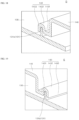
- FIG. 17 is a cross-sectional view partially cut in a state where the air guide 140, the blowing device 150, and the inner panel 130 are coupled.
- FIG. 18 is an enlarged view of portion D of FIG. 17 .
- FIG. 19 is an enlarged view of portion E of FIG. 17 .
- the engagement groove portion 143 may be provided to include a first bent portion 1431, a second bent portion 1432, and a third bent portion 1433 in order to be formed in a groove shape to be stably coupled to the blocking protrusion 131, and at the same time, block the leakage of air.
- the first bent portion 1431 may be bent from an end of the inner panel 130.
- the second bent portion 1432 may be bent from the first bent portion 1431, and provided so that at least a part thereof is in contact with a tip of the blocking protrusion 131.
- the third bent portion 1433 may be bent from the second bent portion 1432.
- the first bent portion 1431, the second bent portion 1432, and the third bent portion 1433 may be integrally formed, and formed in a groove shape.
- the first bent portion 1431 and the third bent portion 1433 can double-block the gap that may be formed between the inner panel 130 and the air guide 140. Accordingly, it is possible to effectively suppress the air flowing through the space formed by coupling the inner panel 130 and the air guide 140 from leaking through this gap.
Landscapes
- Engineering & Computer Science (AREA)
- Physics & Mathematics (AREA)
- Electromagnetism (AREA)
- Chemical & Material Sciences (AREA)
- Combustion & Propulsion (AREA)
- Mechanical Engineering (AREA)
- General Engineering & Computer Science (AREA)
- Human Computer Interaction (AREA)
- Electric Ovens (AREA)
- Multimedia (AREA)
- Signal Processing (AREA)
- Electric Stoves And Ranges (AREA)
Abstract
Description
- The present invention relates to a cooking appliance, and more specifically, to a cooking appliance installed above a heating cooking device.
- The content described in this section merely provides background information on the present invention and does not constitute the related art.
- A cooking appliance is a home appliance that is used for cooking food using microwaves and/or heater heat, which are type(s) of electromagnetic waves. The cooking appliance may generally include a main body forming a cavity therein, which is an accommodation space in which food is placed and cooked, and one or more doors that opens and closes the cavity.
- The related art related to the cooking appliance is disclosed in
Korean Patent Application Laid-Open No. 10-2008-0070408 - When the cooking appliance is installed indoors, it is necessary to consider the efficient use of the cooking appliance, the saving of installation space, etc.
- For this reason, the cooking appliance may be disposed at a location adjacent to a heating cooking device, for example, a heating-type oven, a gas range, etc. Specifically, the cooking appliance may be disposed above the heating cooking device.
- When the cooking appliance is disposed above the heating cooking device, a user can conveniently cook food by reducing his/her movement in an environment where the cooking appliance and the heating cooking device are adjacent to each other. In addition, heat, oil mist, etc. generated from the heating cooking device can be discharged to the outside using the cooking appliance as a hood.
- In a state in which the cooking appliance is disposed above the heating cooking device, the heat, oil mist, etc. generated from the heating cooking device disposed below the cooking appliance may adversely affect an operation of the cooking appliance.
- For example, a display unit may be mounted on a front surface of a door provided in the cooking appliance in order to provide various types of information to the user. The user may receive information on the display unit for a cooking state of the cooked food.
- In addition, the display unit may be connected to another home appliance and may serve as a hub of the home appliance. Then, information other than cooking of food may be obtained through the display unit. In addition, the user may also input commands into the display unit including a touch screen by using a touch input method. The commands might be required for cooking and/or other various commands for controlling other connected devices or input messages for being sent.
- When the cooking appliance is disposed above the heating cooking device, the heat, oil mist, etc. generated from the heating cooking device may penetrate into the display unit and other parts mounted on the door.
- Therefore, it is necessary to suppress or prevent the display unit and other parts mounted on the door of the cooking appliance from being damaged or influenced due to such heat, oil mist, etc. which might result in malfunctioning.
- To solve this issue, it is an object of the present invention to provide a cooking appliance having a display unit provided on a front surface thereof to provide various types of information to the user.
- A further object is to provide a cooking appliance having a display unit provided on a door of the cooking appliance using microwaves.
- A further object is to provide a cooking appliance having a structure being capable of suppressing heat, oil mist, from penetrating into a door.
- A further object is to provide a cooking appliance having a structure being capable of suppressing or preventing a display unit from being contaminated by oil mist.
- A further object is to provide a cooking appliance having a cooling structure of a display module attached to a front surface of a door.
- A further object is to provide a cooking appliance having a structure being capable of suppressing or preventing heat, oil mist, etc. from penetrating into a door by forming an air curtain outside the door.
- A further object is to provide a cooking appliance having a door equipped with a display unit on a front surface thereof and formed with a cooling structure for cooling the display unit and a microwave shielding structure for preventing microwave leakage.
- A further object is to provide a cooking appliance having a structure that suppresses air from leaking through a gap at an edge of an air guide and to improve the cooling of the components inside the door.
- If air leaks from a gap at an edge of the air guide, it may cause the air flowing inside the door to interfere with the air used for forming the air curtain or cooling the inside of the door. Accordingly, there is a need for a structure of suppressing the air from leaking through the gap at the edge of the air guide.
- The objects of the present invention are not limited to the above-described objects, and other objects and advantages not mentioned may be understood by the following description, and will be more clearly understood by embodiments of the present invention. In addition, it will be easily seen that the objects and advantages of the present invention may be realized by a means described in the claims and combinations thereof.
- The objects are solved by the features of the independent claims. Preferred embodiments are given in the dependent claims.
- According to one aspect a cooking appliance is provided, comprising a main body formed with a cavity, and a door for opening and closing the cavity. The door includes a display module disposed on a front of the door; a cooling flow path unit disposed behind the display module, and having a flow path through which air for cooling flows formed therein.
- In a further detailed aspect, a cooking appliance is provided comprising a main body formed with a cavity, and a door for opening and closing the cavity.
- In one or more embodiments, the door includes a display module disposed on a front of the door; and a cooling flow path unit disposed behind the display module and having a flow path through which air for cooling flows formed therein.
- In one or more embodiments, the cooling flow path unit may include an air guide configured to guide the flow of the air introduced into the door; and a blowing device mounted on the air guide.
- In one or more embodiments, the air guide may include at least one inlet through which external air is introduced.
- In one or more embodiments, the display module may include a display unit on which videos or images are displayed
- In one or more embodiments, the display module may include an outer panel disposed behind the display unit, and on which the display unit is mounted.
- In one or more embodiments, the cooling flow path unit may include an inner panel disposed behind the outer panel and mounted on the outer panel.
- In one or more embodiments, the cooling flow path unit may include an air guide disposed between the outer panel and the inner panel and coupled to the inner panel.
- In one or more embodiments, the cooking appliance may include a main body formed with a cavity, and a door for opening and closing the cavity.
- In one or more embodiments, the door may include a display module disposed in front of the door, a cooling flow path unit disposed behind the display module and a shielding unit disposed behind the cooling flow path unit.
- In one or more embodiments, the cooling flow path unit may disposed behind the display module, and may having a flow path through which air for cooling flows formed therein.
- In one or more embodiments, the shielding unit may be disposed behind the cooling flow path unit, and may be configured to shield electromagnetic waves generated from the main body.
- In one or more embodiments, the air flowing through the cooling flow path unit may be branched inside of the cooling flow path unit to be discharged to the top and bottom of the display module.
- In one or more embodiments, in the cooking appliance, when the blowing fan rotates, the external air may flow into the door through an inlet of the air guide, and may flow to be discharged to the outside through a first outlet and a second outlet.
- In one or more embodiments, the air forcibly flowing by the blowing fan may specifically have the following flow path.
- In one or more embodiments, the air may flow into the door from the first aperture of the outer panel and the inlet provided at the location corresponding thereto.
- In one or more embodiments, the air flowing into the door may flow in a downward direction of the door to flow into the blowing fan.
- In one or more embodiments, the air may pass through the blowing fan in the front-rear direction of the door. At this time, the air may pass through the mounting hole of the air guide while passing through the blowing fan.
- In one or more embodiments, the flow direction of the air may be changed from the up-down direction into the front-rear direction of the door at the blowing fan.
- In one or more embodiments, since the front of the mounting hole is closed by the display unit, the air passing through the mounting hole may be branched in front of the air guide in the up-down direction.
- In one or more embodiments, a part of the branched air may flow in an upward direction of the door to be discharged through the first outlet.
- In one or more embodiments, the other part of the branched air may flow in the downward direction of the door to be discharged to the second outlet.
- In one or more embodiments, the air branched on the first outlet and the second outlet may surround the entire door.
- In one or more embodiments, the branched air may surround the front portion of the door.
- In one or more embodiments, this structure can allow the air discharged through the first outlet and the second outlet to form the air curtain on the door, thereby effectively suppressing the heat and oil mist generated from the heating cooling device disposed below the cooking appliance from permeating into the door.
- In one or more embodiments, the cooking appliance may include a main body formed with a cavity, and a door for opening and closing the cavity.
- In one or more embodiments, the door may include a display unit configured to display videos or images, an outer panel disposed behind the display unit and on which the display unit is mounted, an inner panel disposed behind the outer panel, and mounted on the outer panel, an air guide disposed between the outer panel and the inner panel, and coupled to the inner panel, and a blowing device mounted on the air guide.
- In one or more embodiments, the inner panel may include a blocking protrusion protruding from a portion corresponding to an edge of the air guide toward the air guide, and engaged with the air guide to block air from leaking through a gap between the air guide and the inner panel.
- In one or more embodiments, the blocking protrusion may include a first blocking portion formed on a lower portion of the inner panel, and having a longitudinal direction disposed in both side directions of the inner panel, and a pair of second blocking portions provided to be connected to ends of both sides of the first blocking portion, respectively, and having a longitudinal direction disposed in an up-down direction of the inner panel.
- In one or more embodiments, the air guide may include an engagement groove portion provided on an edge in a shape corresponding to the blocking protrusion, and engaged with the blocking protrusion to block air from leaking through the gap between the air guide and the inner panel.
- In one or more embodiments, the engagement groove portion may include a first engagement portion disposed at a location corresponding to the first blocking portion, and having a longitudinal direction disposed in both side directions of the air guide.
- In one or more embodiments, the engagement groove portion may include a second engagement portion disposed at a location corresponding to the second blocking portion, provided as a pair, and having a longitudinal direction disposed in an up-down direction of the air guide.
- In one or more embodiments, the engagement groove portion may include a first bent portion bent from an end of the inner panel, a second bent portion bent from the first bent portion, and provided so that at least a part thereof is in contact with a tip of the blocking protrusion, and a third bent portion bent from the second bent portion.
- In one or more embodiments, the blocking protrusion may include a hook formed to protrude from the second blocking portion.
- In one or more embodiments, the engagement groove portion may include a fitting hole formed in the second engagement portion.
- The fitting hole may be provided at a location corresponding to the hook, and may having the hook fitted therein.
- In one or more embodiments, the hooks may be formed on both sides of the pair of second blocking portions, respectively.
- In one or more embodiments, the fitting holes may be formed in both sides of the pair of second engagement portions, respectively.
- In one or more embodiments, the second engagement portion may include an elastically deformable portion formed on the edge of the air guide so that at least a part thereof is separated from a remaining portion of the second engagement portion, formed with the fitting hole, and provided so that at least a part thereof is elastically deformed when the hook is fitted into the fitting hole.
- In one or more embodiments, a plurality of hooks may be provided, and each of the hooks may be disposed to be spaced apart from each other in a longitudinal direction of the second blocking portion, and a plurality of fitting holes may be provided, and each of the fitting holes may be spaced apart from each other in a longitudinal direction of the second engagement portion and disposed at a location corresponding to each of the hooks.
- In one or more embodiments, the outer panel may include a first outlet disposed on an upper portion, and having the air flowing by the blowing device discharged to the outside therethrough.
- In one or more embodiments, the outer panel may include a second outlet disposed on a lower portion, and having the air flowing by the blowing device discharged to the outside therethrough.
- In one or more embodiments, the air guide may include at least one inlet disposed on an upper portion, and having external air introduced therein, and a mounting hole formed on a lower portion of the inlet, and mounted with the blowing device.
- In one or more embodiments, the blowing device may include a casing disposed in the mounting hole.
- In one or more embodiments, the blowing device may include a blowing fan rotatably mounted in the casing, and flowing air from the rear to the front of the air guide.
- In one or more embodiments, the air forcibly flowing by the blowing fan may be introduced from the inlet to flow in a downward direction of the door to flow into the blowing fan.
- In one or more embodiments, the air forcibly flowing by the blowing fan may pass through the blowing fan in a front-rear direction of the door.
- In one or more embodiments, the air forcibly flowing by the blowing fan may be branched in front of the air guide in an up-down direction, a part of which may flow in an upward direction of the door to be discharged to the first outlet, and the other part of which may flow in a downward direction of the door to be discharged to the second outlet.
- In one or more embodiments, the door may further include a baffle disposed in front of the display unit, surrounding an edge of the display unit, and coupled to the outer panel to mount the display unit on the outer panel.
- In one or more embodiments, the door may further include a front cover disposed in front of the baffle, and provided to surround an edge of the baffle.
- In one or more embodiments, the door may further include a plate disposed behind the inner panel, coupled to the inner panel, and having one side rotatably coupled to the main body.
- In one or more embodiments, the door may further include at least one camera.
- In one or more embodiments, the door may further include a first camera mounted on a lower portion of the outer panel to capture a state of a lower portion of the door, a second camera disposed on an upper portion of the door, mounted by passing through the baffle and the front cover, and configured to capture the front of the door, and a third camera mounted on the plate, disposed to face the cavity, and configured to capture the cavity.
- In one or more embodiments, the door may further include a human detection unit disposed on the upper portion of the door.
- In one or more embodiments, the human detection unit may be mounted by passing through the baffle and the front cover, and/or may be disposed at a location spaced apart from the second camera, and/or may be configured to detect the presence of a user in front of the cooking appliance.
- In the cooking appliance according to the present invention, since the display module is provided on the front of the door, the user can know the cooking situation in the cooking appliance through the display module. The display module can serve as the hub of another home appliance to provide various types of information to the user, thereby enhancing the user's convenience.
- In addition, in the cooking appliance according to the present disclosure, the airflow discharged to the outside of the door through the first outlet and the second outlet can form an air curtain, so that the heat and oil mist rising from the heating cooking device disposed below the cooking appliance can be effectively blocked by the air curtain.
- Accordingly, it is possible to effectively suppress various electronic parts including the display unit provided on the door from being damaged or degraded by the heat and the oil mist. In addition, it is possible to prevent the display unit from being contaminated by the heat and the oil mist and thus giving inconvenience to the user.
- In addition, in the cooking appliance according to the present invention, the air flowing inside the door can be discharged through the first outlet to cool the entire front surface of the display unit. In addition, the air flowing inside the door can effectively cool the heat-generating parts mounted on the rear surface of the display unit and inside the door.
- In addition, in the cooking appliance according to the present invention, a door having all of the display structure, the cooling structure, and the shielding structure of the electromagnetic waves can be formed. The display structure, the cooling structure, and the shielding structure can be coupled to one another to slimly form the door as a whole. Accordingly, it is possible to prevent the thickness of the door from being increased even when all of the display structure, the cooling structure, and the shielding structure are formed on the door.
- In addition, in the cooking appliance according to the present invention, the gap at the edge of the air guide can be blocked by the engagement groove portion and the blocking protrusion, thereby effectively suppressing the air forcibly flowing into the door from leaking at the coupling portion between the edge of the air guide and the inner panel.
- Accordingly, the air forcibly flowing into the door can be suppressed from leaking to the outside of the door to flow along the designed flow path. Due to this structure, it is possible to improve the cooling effect and air curtain forming effect of the door by the forcibly flowing air.
- In addition, the cooking appliance according to the present invention, the hook may be formed on the blocking protrusion, and the engagement groove portion may be formed with the fitting hole at the location corresponding to the hook. Accordingly, the air guide and the inner panel can be stably coupled by fitting the fitting hole onto the hook.
- Due to this structure, it is possible to improve the work efficiency during assembly of the door by not using a separate coupling mechanism such as a bolt, or reducing the number of coupling mechanisms used and at the same time, stably coupling the air guide and the inner panel.
- In addition, in the cooking appliance according to the present invention, when the engagement groove portion is mounted on the blocking protrusion, the first bent portion and the third bent portion can double-block the gap that may be formed between the inner panel and the air guide. Accordingly, the air flowing through the space formed by coupling the inner panel and the air guide can be effectively suppressed from leaking through the gap.
- Detailed effects of the present invention in addition to the above-described effects will be described together with the description of the specific items for practicing the present invention below.
- The above and other objects, features and advantages of the present invention will become more apparent to those of ordinary skill in the art by describing in detail exemplary embodiments thereof with reference to the accompanying drawings, in which:
-
FIG. 1 is a perspective view showing a cooking appliance according to one embodiment; -
FIG. 2 is a view showing a state in which a door inFIG. 1 has been opened; -
FIG. 3A perspective view showing a door of the cooking appliance according to one embodiment; -
FIG. 3B is a view ofFIG. 3A from another direction; -
FIG. 4A is a rear view of the door; -
FIG. 4B is an exploded perspective view showing a part of the door according to one embodiment; -
FIG. 4C is a view ofFIG. 4B from another direction; -
FIG. 5 is an exploded perspective view of the door according to one embodiment; -
FIG. 6 is a view ofFIG. 5 from another direction; -
FIG. 7 is a side cross-sectional view of the door according to one embodiment; -
FIG. 8 is a perspective view showing an outer panel according to one embodiment; -
FIG. 9A is a rear view showing the outer panel according to one embodiment; -
FIG. 9B is a view ofFIG. 8 from another direction; -
FIG. 10 is an exploded perspective view of a display unit and the outer panel; -
FIG. 11 is a view showing an inner panel and an air guide according to one embodiment; -
FIG. 12 is an exploded perspective view ofFIG. 11 ; -
FIG. 13 is a view ofFIG. 12 from another direction; -
FIG. 14 is an enlarged view of a portion A ofFIG. 12 ; -
FIG. 15 is an enlarged view of a portion B ofFIG. 11 ; -
FIG. 16 is an enlarged view of a portion C ofFIG. 11 ; -
FIG. 17 is a cross-sectional view partially cut in a state where the air guide, the blowing device, and the inner panel are coupled; -
FIG. 18 is an enlarged view of portion D ofFIG. 17 ; and -
FIG. 19 is an enlarged view of portion E ofFIG. 17 . - The above-described objects, features, and advantages will be described below in detail with reference to the accompanying drawings, and accordingly, those skilled in the art to which the present invention pertains will be able to easily practice the technical spirit of the present invention. In describing the present invention, when it is determined that a detailed description of a known technique related to the present invention may unnecessarily obscure the gist of the present invention, the detailed description will be omitted. Hereinafter, embodiments according to the present invention will be described in detail with reference to the accompanying drawings. In the drawings, the same reference numerals are used to indicate the same or similar components.
- Although the first, second, etc. are used to describe various components, it goes without saying that these components are not limited by these terms. These terms are only used to distinguish one component from other components, and unless otherwise stated, it goes without saying that the first component may also be the second component.
- Throughout the specification, unless specifically stated otherwise, each component may be singular or plural.
- As used herein, the singular expression includes the plural expression unless the context clearly dictates otherwise. In the present application, terms such as "consisting of" or "comprising" should not be construed as necessarily including all of the various components or various steps described in the specification, and should be construed that some components or some steps may not be included, or additional components or steps may be further included.
- Throughout the specification, when "A and/or B" is used, it means A, B or A and B, unless specifically stated otherwise, and when "C to D" is used, it means greater than or equal to C and smaller than or equal to D unless specifically stated otherwise.
- Throughout the specification, "up-down direction" means the up-down direction of the cooking appliance in a state in which the cooking appliance is installed for daily use. "Left-right direction" means a direction perpendicular to the up-down direction, and the front-rear direction means a direction perpendicular to both the up-down direction and the left-right direction. "Bilateral direction" or "lateral direction" has the same meaning as the left-right direction, and these terms may be used interchangeably in the present specification.
-
FIG. 1 is a perspective view showing a cooking appliance according to one embodiment.FIG. 2 is a view showing a state in which adoor 20 inFIG. 1 has been opened. - The cooking appliance according to the embodiment may be disposed at a location spaced apart from a heating cooking device in an up-down direction above a location where the heating cooking device, for example, a heating-type oven, a gas range, etc. is disposed.
- The placement of the cooking appliance can allow a user to conveniently use cooking devices including the cooking appliance. In addition, the cooking appliance may serve as a hood of the heating cooking device disposed thereunder. In this case, the cooking appliance may be provided with parts for use as a hood.
- The cooking appliance may cook food using microwaves, and/or heater heat, which are type(s) of electromagnetic waves. The cooking appliance may include a
main body 10 in which acavity 11 is formed, and adoor 20 that opens and closes thecavity 11. - Food to be cooked may be placed in the
cavity 11. Thedoor 20 may be disposed in front of thecavity 11 and rotatably mounted on themain body 10 to open and close thecavity 11. - A
vent hole 13 for discharging the air sucked in a suction unit provided on a lower portion of themain body 10 to the outside may be provided in an upper portion of themain body 10. The suction unit may be provided at a lower portion of themain body 10 of the cooking appliance. Accordingly, the cooking appliance may serve as a hood for sucking the air discharged from the heating cooking device disposed thereunder to discharge the air to the outside. - The
main body 10 may further include afront panel 12 provided on an edge of the entrance of thecavity 11, and having one surface disposed to face one surface of achoke member 170 when thedoor 20 is closed to close thecavity 11. - The
front panel 12 may be provided to surround the edge of the entrance of thecavity 11 and protrude with a predetermined width. Accordingly, when thedoor 20 is closed, the edge portion of thedoor 20 and thecavity 11 may overlap each other. - This structure can allow the
front panel 12 to seal thecavity 11 in a state in which thedoor 20 is closed, thereby suppressing the oil, moisture, oil mist, etc. generated in the process of cooking food placed in thecavity 11 from being discharged to the outside through an inlet of thecavity 11. -
FIG. 3A is a perspective view showing thedoor 20 of the cooking appliance according to one embodiment.FIG. 3B is a view ofFIG. 3A from another direction. -
FIG. 4A is a rear view of thedoor 20.FIG. 4B is an exploded perspective view showing a part of thedoor 20 according to one embodiment.FIG. 4C is a view ofFIG. 4B from another direction. - The
door 20 may include adisplay module 21, a coolingflow path unit 22, and ashielding unit 23. Thedisplay module 21 may be disposed in front of thedoor 20, and the user may see the inside of thecavity 11 of the cooking appliance through thedisplay module 21. - The cooling
flow path unit 22 may be disposed behind thedisplay module 21, and a flow path through which air for cooling flows may be formed therein. The air flowing into thedoor 20 may flow into thedoor 20 through the coolingflow path unit 22 to cool thedoor 20. - The shielding
unit 23 may be disposed behind the coolingflow path unit 22, and may shield electromagnetic waves generated from themain body 10. The shieldingunit 23 may protect the user by blocking the electromagnetic waves generated in thecavity 11 and propagating to the outside of the cooking appliance. - For example, the shielding
unit 23 may serve to block the electromagnetic waves (microwaves) generated to cook food in themain body 10 from being discharged to the outside of thedoor 20. - The cooling
flow path unit 22 may be provided to cool electronic components mounted inside thedoor 20, including adisplay unit 110 mounted on thedisplay module 21. The air for cooling thedoor 20 may flow inside the coolingflow path unit 22. Thedisplay unit 110 may be formed in a thin shape and provided so that an area of thedisplay unit 110 occupies most of one surface of thedoor 20. - Accordingly, the
display unit 110 can be formed to occupy most of the area of the front portion of thedoor 20, and the placement area of thedisplay unit 110 can be increased, thereby improving user visibility. The user may conveniently check various types of information through thedisplay unit 110 provided with a large screen. - Since the size of the
display unit 110 is increased, the amount of heat generated may increase. Accordingly, thedisplay unit 110 in thedoor 20 needs to be effectively cooled. In the embodiment, the coolingflow path unit 22 through which the cooling air flows may be separately provided. - The cooling
flow path unit 22 may be disposed behind thedisplay unit 110 so that cooling air flows, and thus thedisplay unit 110 may be effectively cooled by the air flowing through the coolingflow path unit 22. In addition, a heat-generating part mounted on thedisplay module 21 may be cooled by the air flowing through the coolingflow path unit 22. In other words, the coolingflow path unit 22 may cool thedisplay module 21 provided with thedisplay unit 110 and other various heat-generating parts. - In order to effectively cool the
display unit 110, theentire display unit 110 may be provided to be exposed to the air flowing through the coolingflow path unit 22. In addition, the airflow discharged to the outside of thedoor 20 through the coolingflow path unit 22 may form an air curtain to block heat and oil mist rising from the heating cooking device disposed below the cooking appliance. - To this end, the air flowing through the cooling
flow path unit 22 may be branched inside the coolingflow path unit 22 to be discharged to the top and bottom of thedisplay module 21. - The cooling air is branched inside the cooling
flow path unit 22 and discharged to the top and bottom of thedisplay module 21, so that the cooling air can flow while in contact with the entire rear surface of thedisplay unit 110 to effectively cool thedisplay unit 110. - In addition, the cooling air is discharged to each of the top and bottom of the
display module 21 to effectively form the air curtain around the display and thedoor 20, so that the heat and oil mist rising from the heating cooking device disposed below the cooking appliance can be effectively blocked by the air curtain. - The
display module 21 may be provided with thedisplay unit 110, a camera, and other electronic parts, and the coolingflow path unit 22 may be provided with electronic parts such as ablowing device 150 operated by a motor. Accordingly, the shieldingunit 23 configured to shield the electromagnetic waves generated from the main body may be provided behind the coolingflow path unit 22 in order to protect the user and the electronic parts from electromagnetic waves. - The
display unit 110 and various electronic parts may be disposed in thedisplay module 21, the coolingflow path unit 22 in which the flow path of the air for cooling thedisplay module 21 is formed may be disposed behind thedisplay module 21, and the shieldingunit 23 configured to shield electromagnetic waves from reaching the electronic parts provided in thedisplay module 21 may be disposed behind the coolingflow path unit 22. - In the embodiment, the
display module 21 configured to provide various types of information and convenience to the user may be disposed on the front surface of the cooking appliance, that is, on the front of thedoor 20. In addition, in the embodiment, there is a need for a structure that effectively cools the parts such as thedisplay unit 110 provided in thedisplay module 21, effectively cools the inside of thedoor 20 provided with thedisplay unit 110 and the like, and at the same time, forms the flow path of the cooling air for forming the air curtain around thedoor 20, and also protects the electronic parts mounted on thedoor 20 from electromagnetic waves. - In order to satisfy this need, the
display module 21 may be disposed at the front of thedoor 20, the coolingflow path unit 22 may be disposed behind thedisplay module 21, and the shieldingunit 23 may be disposed behind the coolingflow path unit 22. - In other words, in order to implement the door structure according to the above-described embodiment, the
display module 21, the coolingflow path unit 22, and the shieldingunit 23 that play their own roles may be sequentially disposed on thedoor 20 from the front to rear in thedoor 20. - In addition, the
display module 21, the coolingflow path unit 22, and the shieldingunit 23 may be provided to be stably coupled to each other to prevent the cooling air from flowing out to the outside of thedoor 20 through other portions other than afirst outlet 123 disposed at an upper portion of thedisplay module 21 and asecond outlet 124 at a lower portion of thedisplay module 21. Hereinafter, thedoor 20 implemented using the above-described structure will be described in detail. - The
display module 21 may include thefirst outlet 123 and thesecond outlet 124. Thefirst outlet 123 may be disposed at the upper portion of thedisplay module 21, and the air flowing inside thedisplay module 21 may be discharged to the outside through thefirst outlet 123. - The
second outlet 124 may be disposed at the lower portion of thedisplay module 21, and the air flowing inside thedisplay module 21 may be discharged to the outside through thesecond outlet 124. In other words, the air flowing inside thedoor 20 may be discharged to the outside through thefirst outlet 123 and thesecond outlet 124 respectively disposed at the upper and lower portions of thedoor 20, so that the air can flow through the entire inside of thedoor 20 to effectively cool theentire door 20. - The
display module 21 may include thedisplay unit 110 and anouter panel 120. Thedisplay unit 110 may be disposed on the front surface of thedoor 20 to display videos or images. - The
display unit 110 may display information necessary for cooking to provide the information to the user. In addition, thedisplay unit 110 may receive a user's command in a touch recognition method. - Meanwhile, the
display unit 110 may be connected to communicate with other home appliances, and cameras, locks, etc. provided in the front door. In addition, thedisplay unit 110 may be connected to communicate with an external device required by the user. - The user may receive information necessary for operations of home appliances, visits by outsiders, and other aspects of daily life from the
display unit 110, and transmit commands to home appliances and other devices connected to thedisplay unit 110 using thedisplay unit 110. - Accordingly, the
door 20 including thedisplay unit 110 may serve as a kind of Internet of Things hub that transmits information about home appliances and other devices necessary for daily life to the user, and transmits the user's commands to these devices. - The
outer panel 120 may be disposed behind thedisplay unit 110, and thedisplay unit 110 may be mounted thereon. Theouter panel 120 may have a hollow 1201 and may be provided in a shape having a predetermined width in the front-rear direction of thedoor 20. - The hollow 1201 of the
outer panel 120 may be closed by the rear surface of thedisplay unit 110. The air flowing inside theouter panel 120 may collide with the rear surface of thedisplay unit 110 exposed to the hollow 1201 of theouter panel 120. Accordingly, the air flowing inside theouter panel 120 may come into contact with the rear surface of thedisplay unit 110 to cool thedisplay unit 110. - In addition, the air passing through a blowing
fan 152 may be exposed to the hollow 1201 of theouter panel 120 to cool heat-generating parts such as aspeaker 260, amicrophone 270, acommunication unit 280, and acontrol board 290 to be disposed. - Since the
outer panel 120 has the above-described structure, theouter panel 120 may have an interior space, and various parts may be built in in the interior space. A width in the front-rear direction of thedoor 20 may be substantially determined by theouter panel 120. - A
first aperture 121 into which air flows may be formed in an upper end of theouter panel 120. A plurality offirst apertures 121 may be provided. Each of thefirst apertures 121 may be provided so that a plurality of slit-shaped holes are arranged at intervals. This structure can somewhat suppress foreign substances from flowing into thedoor 20 through thefirst aperture 121. - A
handle 122 may be provided on one side of theouter panel 120 to be used when the user opens and closes thedoor 20. Thehandle 122 may be formed, for example, by recessing a side portion of theouter panel 120. - A
button device 300 may be mounted on one side of theouter panel 120, for example, just below a location where thehandle 122 is formed. The user may supply electricity to the cooking appliance or cut off the electricity supply by manipulating thebutton device 300. Specific manipulation for the operation of the cooking appliance is possible by inputting commands into thedisplay unit 110. - The
outer panel 120 may support various parts such as thedisplay unit 110, thespeaker 260, themicrophone 270, thecommunication unit 280, and thecontrol board 290, and may be formed with thefirst aperture 121 into which external air flows, and thefirst outlet 123 and thesecond outlet 124 through which air is discharged. - Meanwhile, the
door 20 may be provided with a camera. The images captured by the camera may be reproduced on thedisplay unit 110, and the user may view images inside thecavity 11 or of the lower portion of the cooking appliance through thedisplay unit 110. The camera may include afirst camera 210, asecond camera 220, and athird camera 230. - The
first camera 210 may be mounted on a lower portion of theouter panel 120 to capture a state of the lower portion of thedoor 20. Since thefirst camera 210 is mounted on the lower portion of theouter panel 120 so that a gaze direction faces the lower portion of the cooking appliance, thefirst camera 210 may capture the heating cooking device disposed below the cooking appliance. - The user may observe the state of the heating cooking device and the state of food being cooked on the heating cooking device by the image captured by the
first camera 210 and reproduced on thedisplay unit 110. - The
second camera 220 may be disposed on the upper portion of thedoor 20 and may capture the front of thedoor 20. Thesecond camera 220 may capture the front of the cooking appliance. - The
second camera 220 may be provided to pass through abaffle 190 and afront cover 200, which will be described below. The user may observe the situation in front of the cooking appliance captured and recorded by thesecond camera 220. - Meanwhile, the
second camera 220 may capture the user in front of the cooking appliance. Accordingly, thesecond camera 220 may be used for the user to make a video call with other people in a remote location outside the front door using thedisplay unit 110. - The
third camera 230 may be mounted on aplate 160 to be described below, may be disposed to face thecavity 11, and may capture thecavity 11. In other words, the gaze of thethird camera 230 may be provided to face thecavity 11 to capture the situation of thecavity 11. The user may observe a situation in which food is cooked in thecavity 11 through the image captured by thethird camera 230. - The
door 20 may include ahuman detection unit 240 disposed on the upper portion of thedoor 20, mounted by passing through thebaffle 190 and thefront cover 200, disposed at a location spaced apart from thesecond camera 220, and configured to detect the presence of the user in front of the cooking appliance. - The
human detection unit 240 may detect whether there is a person in front of thedoor 20 by, for example, infrared recognition or gesture recognition. A control unit provided in the cooking appliance may identify whether there is a user in front of the cooking appliance through thehuman detection unit 240. - When there is a user, for example, the control unit may operate the
display unit 110 to activate the functions of the cooking appliance necessary for the user's convenience and safety by taking an action to enable the user to use thedisplay unit 110 immediately. - The door may include a
latch 250 mounted on a side of theplate 160, which has a part formed to protrude from theplate 160. Thelatch 250 may be formed in a structure that is caught in a groove formed in thefront panel 12 of thedoor 20. Thelatch 250 may stably maintain the closed state of thedoor 20. -
FIG. 5 is an exploded perspective view of thedoor 20 according to one embodiment.FIG. 6 is a view ofFIG. 5 from another direction. The coolingflow path unit 22 may include aninner panel 130, anair guide 140, and ablowing device 150. - The
inner panel 130 may be disposed behind theouter panel 120 and mounted on theouter panel 120. Also, theinner panel 130 may be disposed behind theair guide 140. Theair guide 140 to be described below may be mounted on theinner panel 130. Theinner panel 130 along with theair guide 140 may form a space in which the air sucked into thedoor 20 flows. Theinner panel 130 may be mounted with theair guide 140 and coupled to theplate 160 to provide the space in which the air flowing into thedoor 20 flows. - The
air guide 140 may be configured to guide the flow of the air introduced into thedoor 20. Theair guide 140 may be disposed between theouter panel 120 and theinner panel 130, and coupled to theinner panel 130. Theair guide 140 may guide the flow of air flowing into thedoor 20 from the outside, and form the space in which the air may flow. - The
blowing device 150 may be mounted on theair guide 140. Theblowing device 150 may forcibly flow the air flowing into theair guide 140 from the rear to the front of theair guide 140. - The shielding
unit 23 may include theplate 160 and thechoke member 170. Theplate 160 may be disposed behind theinner panel 130, may be coupled to theinner panel 130, and may have one side rotatably coupled to themain body 10. As theplate 160 rotates, thedoor 20 may be rotated to open and close thecavity 11 of the cooking appliance. - The
plate 160 may be coupled to theinner panel 130 to form a flow path of air for cooling and at the same time, may form an inner surface of thedoor 20 with a shielding structure for preventing the leakage of electromagnetic waves, that is, thechoke member 170. - The
choke member 170 may be disposed behind theplate 160, may be coupled to theplate 160, and may block the electromagnetic waves generated from themain body 10 from being discharged to the outside. Thechoke member 170 may be generally provided in a quadrangular shape having a hollow, and provided to surround an edge portion of theplate 160. - The
display module 21 may further include thebaffle 190 and thefront cover 200. Thebaffle 190 may be disposed in front of thedisplay unit 110, may surround the edge of thedisplay unit 110, and may be coupled to theouter panel 120 to mount thedisplay unit 110 on theouter panel 120. - The
baffle 190 is generally formed in a quadrangular shape having a hollow to surround the edge of thedisplay unit 110, and thus may serve as a bezel of thedisplay unit 110. - The
front cover 200 may be disposed in front of thebaffle 190, and provided to surround the edge of thebaffle 190. Thefront cover 200 may be generally formed in a quadrangular shape having a hollow, and may serve to stably couple thedisplay unit 110 and thebaffle 190 to theouter panel 120. -
FIG. 7 is a side cross-sectional view of thedoor 20 according to one embodiment.FIG. 8 is a perspective view showing theouter panel 120 according to one embodiment.FIG. 9A is a rear view showing theouter panel 120 according to one embodiment.FIG. 9B is a view ofFIG. 8 from another direction. -
FIG. 10 is an exploded perspective view of thedisplay unit 110 and theouter panel 120.FIG. 11 is a view showing theinner panel 130 and theair guide 140 according to one embodiment. - Referring to
FIG. 10 , theouter panel 120 may include thespeaker 260, themicrophone 270, and thecommunication unit 280. At least onespeaker 260 may be mounted on the side of theouter panel 120. Thespeaker 260 may generate a voice, an alarm sound, etc. necessary for operating the cooking appliance. In addition, thespeaker 260 may generate all voices, alarm sounds, etc. for thedoor 20 including thedisplay unit 110 of thedoor 20 to serve as an Internet of Things hub. - The
microphone 270 may be mounted at the top of theouter panel 120 and may receive the user's voice. The user may input voice commands to operate the cooking appliance through themicrophone 270. In addition, themicrophone 270 may play a part of the role for thedoor 20 to serve as an Internet of Things hub. - The
communication unit 280 may be mounted on theouter panel 120 at a location spaced apart from thespeaker 260 and themicrophone 270. Since thedoor 20 serves as an Internet of Things hub, thecommunication unit 280 provided in thedoor 20 is appropriately provided to perform various types of wired or wireless communication functions. - Accordingly, a plurality of
communication units 280 may be provided, and eachcommunication unit 280 may be provided as a device corresponding to a different communication method. - For example, the
communication unit 280 may be provided as a wireless communication device, and eachcommunication unit 280 may be provided as any one of a ZigBee communication device, a Wi-Fi communication device, a jet wave communication device, and a Bluetooth communication device. However, the communication method of thecommunication unit 280 is not limited thereto, and thecommunication unit 280 may also be provided as a wired communication device. - Meanwhile, the
control board 290 for controlling the cooking appliance may be mounted on theouter panel 120. A control unit configured to control the cooking appliance may be implemented on thecontrol board 290. - The
outer panel 120 may be provided with aholder 120a, anopening hole 120b, a first throughhole 120c, a second throughhole 120d, a mountingguide 120e, and afitting projection 120f. - The
holder 120a may be provided to support thespeaker 260. Theholder 120a may be formed to protrude from an inner wall of theouter panel 120, a part of which may have an arc shape to correspond to a circular shape of thespeaker 260. - The
speaker 260 may be mounted on theholder 120a and provided on theouter panel 120. Since a pair ofspeakers 260 are provided, a pair ofholders 120a may also be provided and formed at a location corresponding to each of the pair ofspeakers 260. - The
opening hole 120b may be formed to pass through the bottom of theouter panel 120. Thefirst camera 210 may be disposed at a location adjacent to theopening hole 120b to be able to view the lower side of theouter panel 120 through theopening hole 120b. - The first through
hole 120c may be formed in the side of theouter panel 120. The first throughhole 120c may be provided adjacent to a location where thespeaker 260 is disposed. The first throughhole 120c may allow thespeaker 260 to communicate with the outside and at the same time, may be formed in a mesh shape in order to suppress thespeaker 260 from being exposed to the outside. - The
speaker 260 may communicate with the outside of theouter panel 120 through the first throughhole 120c to effectively transmit an alarm and other voices to the user. Since a pair ofspeakers 260 are provided, a pair of first throughholes 120c may also be provided and formed at a location corresponding to each of the pair ofspeakers 260. - The second through
hole 120d may be formed in a lower portion of one side of theouter panel 120 to pass through theouter panel 120. A part of thebutton device 300 mounted inside theouter panel 120 through the second throughhole 120d may be exposed to the outside of theouter panel 120. The user may manipulate thebutton device 300 by contacting the exposed portion of theouter panel 120. - The mounting
guide 120e may be formed on the inner wall of theouter panel 120 to support the plurality ofcommunication units 280. Accordingly, the mountingguide 120e may be provided in the same number as the plurality ofcommunication units 280. The mountingguide 120e may guide thecommunication unit 280 to be mounted on theouter panel 120. - For example, the mounting
guide 120e may be provided so that a projection having a shape corresponding to the edge of thecommunication unit 280 is formed on the inner wall of theouter panel 120. Each of the plurality of mountingguides 120e may be provided to have a shape and size corresponding to the shape and size of each of the plurality ofcommunication units 280. - The
fitting projection 120f may be formed to protrude from the inner wall of theouter panel 120. A plurality offitting projections 120f may be provided and disposed to be spaced apart from each other. Thecontrol board 290 may be fitted into thefitting projections 120f. For example, thefitting projection 120f may be disposed at a location adjacent to the edge of the plate-shapedcontrol board 290. - Accordingly, the
control board 290 may have corners fitted into thefitting projections 120f and may be mounted on theouter panel 120. A shape fitting structure corresponding to the shape of thecontrol board 290 may be formed on thefitting projection 120f so that the corner of thecontrol board 290 is fitted. - As shown in
FIG. 8 , thefirst outlet 123 may be disposed on the upper portion of theouter panel 120, and thesecond outlet 124 may be disposed on the lower portion of theouter panel 120. - The
first outlet 123 may be disposed on the upper portion of theouter panel 120, and the air flowing by theblowing device 150 may be discharged to the outside. Thesecond outlet 124 may be disposed on the lower portion of theouter panel 120, and the air flowing by theblowing device 150 may be discharged to the outside. - Meanwhile, referring to
FIG. 3B , when thedoor 20 is assembled, thefirst outlet 123 and thesecond outlet 124 may be partially blocked by thebaffle 190 and thefront cover 200. At this time, holes for discharging air may be formed at locations corresponding to thefirst outlet 123 and thesecond outlet 124 in thebaffle 190. - The
first outlet 123 may be provided at a location adjacent to an upper end of thedisplay unit 110, and thesecond outlet 124 may be provided at a location adjacent to a lower end of thedisplay unit 110. Accordingly, the air forcibly flowing inside thedoor 20 by theblowing device 150 may be discharged to the outside at locations adjacent to the upper and lower ends of thedisplay unit 110 through thefirst outlet 123 and thesecond outlet 124. - The air discharged through the
first outlet 123 may form the air curtain on the upper portion of thedoor 20. In addition, the air discharged through thesecond outlet 124 may form the air curtain on the lower portion of thedoor 20. - The air curtain means a means for blocking the permeation of an external airflow into the
door 20. In the embodiment, a boundary surface or a boundary zone in which the flow of air discharged from the inside of thedoor 20 through thefirst outlet 123 and thesecond outlet 124 forms a boundary against the flow of the external air may be referred to as an air curtain. - The air curtain formed by the air discharged from the inside of the
door 20 through thefirst outlet 123 and thesecond outlet 124 may suppress the permeation of external air into thedoor 20. - Since the heating cooking device is disposed below the cooking appliance, the heat generated when the heating cooking device is used and the oil mist generated from the food being cooked may rise and permeate into the cooking appliance.
- The heat transmitted from the heating cooking device to the cooking appliance may damage parts of the
door 20 provided in the cooking appliance. In particular, parts in which thedisplay unit 110 and circuits, elements, etc. related to its operation are embedded may be vulnerable to heat. - In addition, the oil mist transmitted from the food being cooked may be attached to the
door 20 provided in the cooking appliance. The oil mist may be attached to the surface of thedisplay unit 110 to lower the image quality of thedisplay unit 110, and attached to the surfaces of other parts mounted on thedoor 20 to damage these parts. - In the embodiment, the airflow discharged to the outside of the
door 20 through thefirst outlet 123 and thesecond outlet 124 provided in thedoor 20 forms the air curtain, so that the heat and oil mist rising from the heating cooking device disposed below the cooking appliance can be effectively blocked by the air curtain. - Accordingly, it is possible to effectively suppress various electronic parts including the
display unit 110 provided in thedoor 20 from being damaged or degraded by the heat and the oil mist. - Referring to
FIG. 11 , theair guide 140 may include aninlet 141 and a mountinghole 142. Theinlet 141 may be disposed on an upper portion of theair guide 140, external air may be introduced through theinlet 141, and at least oneinlet 141 may be provided. - The
inlet 141 may be disposed at a location corresponding to thefirst aperture 121 provided on the upper portion of theouter panel 120. Accordingly, the external air may pass through thefirst aperture 121 of theouter panel 120 to flow into thedoor 20 through theinlet 141. - The mounting
hole 142 may be formed in a lower portion of theinlet 141 in theair guide 140, and theblowing device 150 may be mounted therein. The mountinghole 142 may be formed to pass through theair guide 140 in the front-rear direction of thedoor 20. - Accordingly, air may flow from the upper portion to the lower portion of the
air guide 140 through theinlet 141, and its direction may be changed, so that the air may flow from the rear to the front of theair guide 140 through the mountinghole 142. - The
blowing device 150 may include acasing 151 and the blowingfan 152. Thecasing 151 may be disposed in the mountinghole 142 and formed with a hollow, and the blowingfan 152 may be mounted in the hollow. - The blowing
fan 152 may be rotatably mounted in thecasing 151, and may flow air from the rear to the front of theair guide 140. The blowingfan 152 may receive electricity and rotate to flow air inside thedoor 20. - By the rotation of the blowing
fan 152, external air may flow into thedoor 20 through theinlet 141, and may be discharged to the outside of thedoor 20 through thefirst outlet 123 and thesecond outlet 124. The mountinghole 142 of theair guide 140 may be formed in the middle of thecasing 151 and formed to correspond to the location, area, and shape of the hollow in which the blowingfan 152 is disposed. - Hereinafter, the airflow inside the
door 20 will be described in detail with reference toFIG. 7 . InFIG. 7 , the airflow is indicated by arrows. - As the blowing
fan 152 rotates, external air may flow into thedoor 20 through theinlet 141 of theair guide 140, and flow to be discharged to the outside of thedoor 20 through thefirst outlet 123 and thesecond outlet 124. - The air forcibly flowing by the
blowing device 150 may be introduced from theinlet 141 formed at an upper position of thedoor 20 to flow in a downward direction of thedoor 20 to be introduced into theblowing device 150. And then, the air may pass through theblowing device 150 in a front-rear direction of thedoor 20, and may be branched in front of theair guide 140 in an up-down direction. And then, a part of the air may flow in an upward direction of thedoor 20 to be discharged to afirst outlet 123 formed at an upper position of thedoor 20, and the other part of the air may flow in the downward direction of thedoor 20 to be discharged to asecond outlet 124 formed at an lower position of thedoor 20. - The air forcibly flowing by the blowing
fan 152 may specifically have the following flow path of the airflow. The air may flow into thedoor 20 from thefirst aperture 121 of theouter panel 120 and theinlet 141 provided at a location corresponding thereto. The air flowing into thedoor 20 may flow downward from thedoor 20 to flow into the blowingfan 152. - The air may pass through the blowing
fan 152 in the front-rear direction of thedoor 20. At this time, the air may pass through the mountinghole 142 of theair guide 140 while passing through the blowingfan 152. The flow direction of the air in the blowingfan 152 may be changed from the up-down direction of thedoor 20 to the front-rear direction thereof. - Since the front of the mounting
hole 142 is blocked by thedisplay unit 110, the air passing through the mountinghole 142 may be branched in the up-down direction in front of theair guide 140. - A part of the branched air may flow upward from the
door 20 and may be discharged through thefirst outlet 123. The other part of the branched air may flow downward from thedoor 20 and may be discharged through thesecond outlet 124. - The air branched from the
first outlet 123 and thesecond outlet 124 may surround theentire door 20. In particular, the branched air may surround the front surface of thedoor 20. This structure can allow the air discharged from thefirst outlet 123 and thesecond outlet 124 to form the air curtain on thedoor 20, thereby effectively suppressing the heat and oil mist generated from the heating cooking device disposed below the cooking appliance from permeating into thedoor 20. - Meanwhile, at least a part of the air discharged from the
first outlet 123 may come into contact with the front surface of thedisplay unit 110 while moving downward by gravity to cool thedisplay unit 110. - In addition, the above-described airflow structure inside the
door 20 may allow the air flowing into thedoor 20 to flow through the entire inside of thedoor 20. For example, the air may flow in the entire space formed by the rear surface of thedisplay unit 110 and theouter panel 120. - Accordingly, the air flowing inside the
door 20 may cool the entire rear surface of thedisplay unit 110, and effectively cool theouter panel 120 and other parts mounted on other portions of thedoor 20. - In particular, the
outer panel 120 may be provided with parts that generate heat, such as thespeaker 260, themicrophone 270, thecommunication unit 280, and thecontrol board 290. These heat-generating parts may be disposed over the entireouter panel 120. Accordingly, the air may flow through the entire inside of theouter panel 120, thereby effectively cooling these heat-generating parts. - As shown in
FIG. 7 , thefirst aperture 121 and theinlet 141 into which air flows may communicate with each other. As the blowingfan 152 rotates, the external air may flow into theair guide 140 through thefirst aperture 121 and theinlet 141 to flow toward theblowing device 150 through the space formed by theinner panel 130 and theair guide 140. - The air may flow toward the blowing
fan 152 of theblowing device 150 in the space formed by theplate 160. The air may pass through the blowingfan 152 and collide with the rear surface of thedisplay unit 110 disposed to face the blowingfan 152 to cool thedisplay unit 110. - After the air passing through the blowing
fan 152 collides with the rear surface of thedisplay unit 110, the flow may be branched in the upward and downward direction of thedisplay unit 110. The air directed to the upper side of thedisplay unit 110 may be discharged to the outside of thedoor 20 through thefirst outlet 123 provided on the upper portion of theouter panel 120. The air flowing downward from thedisplay unit 110 may be discharged to the outside of thedoor 20 through thesecond outlet 124 provided on the lower portion of theouter panel 120. - In the embodiment, the air flowing inside the
door 20 can cool the entire front surface of thedisplay unit 110 while being discharged through thefirst outlet 123. In addition, the air flowing inside thedoor 20 can effectively cool the heat-generating parts mounted on the rear surface of thedisplay unit 110 and inside thedoor 20. -
FIG. 12 is an exploded perspective view ofFIG. 11 .FIG. 13 is a view ofFIG. 12 from another direction. - Referring to
FIG. 13 , the mountinghole 142 may be formed in the middle of theair guide 140. Thecasing 151 has a hollow having a location, size, and shape corresponding to the mountinghole 142, and the blowingfan 152 may be disposed in the hollow. Thecasing 151 may be disposed at a location corresponding to the hollow and the mountinghole 142 of theair guide 140 and mounted on one surface of theair guide 140. - A hollow 130a may be formed in the
inner panel 130. Since the hollow 130a of theinner panel 130 is blocked by theplate 160, the air introduced through theinlet 141 may not leak into the hollow 130a of theinner panel 130. Accordingly, theinner panel 130 and theplate 160 together may form a flow path of the air through which the air cooling the inside of thedoor 20 flows. - As shown in
FIG. 12 , theinner panel 130 may include a blockingprotrusion 131 protruding from a portion corresponding to the edge of theair guide 140 toward theair guide 140, and engaged with theair guide 140 to block the air from leaking through a gap between the air guide and theinner panel 130. - The blocking
protrusion 131 may generally be formed on a portion of theinner panel 130 corresponding to the edge of theair guide 140. The blockingprotrusion 131 can suppress the air from leaking to the outside of the air guide through the gap between theinner panel 130 and theair guide 140 at the edge portion of theair guide 140 when theinner panel 130 and theair guide 140 are coupled. - The blocking
protrusion 131 may include afirst blocking portion 131a and asecond blocking portion 131b. Thefirst blocking portion 131a and thesecond blocking portion 131b may protrude from one surface of theinner panel 130 toward theair guide 140. - The
first blocking portion 131a may be formed on a lower portion of theinner panel 130, and may have a longitudinal direction disposed in both side directions of theinner panel 130. A pair ofsecond blocking portions 131b may be provided to be connected to ends of both sides of thefirst blocking portion 131, respectively, and may have a longitudinal direction disposed in an up-down direction of theinner panel 130. - The
air guide 140 may include anengagement groove portion 143 having a structure capable of being engaged with the blockingprotrusion 131. Theengagement groove portion 143 may be provided on the edge of theair guide 140 in a shape corresponding to the blockingprotrusion 131, and engaged with the blockingprotrusion 131 to block the air from leaking through the gap between the air guide and theinner panel 130. - Since the
engagement groove portion 143 of theair guide 140 may have a groove and the blockingprotrusion 131 of theinner panel 130 corresponding thereto is formed to protrude, theengagement groove portion 143 may be coupled to be engaged with the blockingprotrusion 131. - Accordingly, the gap at the edge of the
air guide 140 can be blocked by theengagement groove portion 143 and the blockingprotrusion 131, thereby effectively suppressing the air forcibly flowing into thedoor 20 from leaking at the coupling portion of the edge of theair guide 140 and theinner panel 130. - Accordingly, the air forcibly flowing into the
door 20 may be suppressed from leaking to the outside of thedoor 20 to flow along the designed flow path. Due to this structure, it is possible to improve the cooling effect and air curtain forming effect of thedoor 20 by the forcibly flowing air. - The
engagement groove portion 143 may include afirst engagement portion 143a and asecond engagement portion 143b. Thefirst engagement portion 143a may be disposed at a location corresponding to thefirst blocking portion 131a, and may have a longitudinal direction disposed in both side directions of theair guide 140. - The
second engagement portion 143b may be disposed at a location corresponding to thesecond blocking portion 131b, provided as a pair, and may have a longitudinal direction disposed in an up-down direction of theair guide 140. - The
first blocking portion 131a and thefirst engagement portion 143a can be coupled to be engaged with each other, and thesecond blocking portion 131b and thesecond engagement portion 143b can be coupled to be engaged with each other, thereby suppressing the air from leaking at the edge of theair guide 140. - The
air guide 140 may include anupper portion 140a in which theinlet 141 is formed and alower portion 140b in which theblowing device 150 is disposed. When theair guide 140 and theinner panel 130 are coupled, thelower portion 140b may be generally disposed at a location corresponding to the hollow 130a of theinner panel 130. - When looking down at the
air guide 140 from the upper portion of thedoor 20, a cross-sectional area of theupper portion 140a of theair guide 140 may be formed to be greater than a cross-sectional area of thelower portion 140b. As the cross-sectional area of theupper portion 140a is expanded, the cross-sectional area of theinlet 141 may also be expanded. Accordingly, in theair guide 140, as theinlet 141 through which air is introduced is expanded, external air may be easily introduced into theair guide 140. When looking down at theair guide 140 from the upper portion of thedoor 20, The cross-sectional area of theupper portion 140a may be at least partially increased in the direction toward theinlet 141. Accordingly, the cross-sectional area of theinlet 141 may be more sufficiently expanded in order that external air may be easily introduced into theair guide 140. - Meanwhile, the
lower portion 140b of theair guide 140 has a smaller cross-sectional area than that of theupper portion 140a, but since thelower portion 140b of theair guide 140 corresponds to the hollow 130a of theinner panel 130, the airflow space in the portion corresponding to thelower portion 140b may be expanded toward theplate 160 by the hollow 130a of theinner panel 130. As a result, thelower portion 140b of theair guide 140 may also have a shape in which the airflow space is expanded by the hollow 130a of theinner panel 130. - In other words, the
lower portion 140b of theair guide 140 corresponding to the hollow 130a of theinner panel 130 is formed to have a smaller cross-sectional area than that of theupper portion 140a of theair guide 140, but the flow space of thelower portion 140b of theair guide 140 may be expanded to theplate 160 by the hollow 130a of theinner panel 130. - Accordingly, the
upper portion 140a and thelower portion 140b of theair guide 140 may have the shape of an expanded cross-sectional area due to the above-described structure. Accordingly, the airflow space formed by coupling theair guide 140 and theinner panel 130 in the structure in which theair guide 140 and theinner panel 130 are coupled may be sufficiently wide, and the air may be smoothly introduced from the outside and may also smoothly pass through theblowing device 150 mounted on thelower portion 140b of theinner panel 130. - In addition, due to the decrease in the cross-sectional area of the
lower portion 140b of theair guide 140, conversely, the space in which the air passing through theblowing device 150 is discharged from thelower portion 140b of theair guide 140 may be expanded. At this time, the air passing through theblowing device 150 may pass through the hollow 1201 of theouter panel 120 and come into contact with thedisplay unit 110 to cool thedisplay unit 110. - The above-described structure can allow the
door 20 to have a slim overall structure and increase the flow rate of air flowing therein, thereby improving the cooling efficiency of thedoor 20. -
FIG. 14 is an enlarged view of a portion A ofFIG. 12 .FIG. 15 is an enlarged view of a portion B ofFIG. 11 .FIG. 16 is an enlarged view of a portion C ofFIG. 11 . - The blocking
protrusion 131 may include ahook 1311 formed to protrude from thesecond blocking portion 131b. Theengagement groove portion 143 may include afitting hole 1434 formed in thesecond engagement portion 143b, provided at a location corresponding to thehook 1311, and having thehook 1311 fitted therein. - The blocking
protrusion 131 may be formed with thehook 1311, and theengagement groove portion 143 may be formed with thefitting hole 1434 at the location corresponding to thehook 1311. Accordingly, theair guide 140 and theinner panel 130 may be stably coupled by fitting thefitting hole 1434 onto thehook 1311. - Due to this structure, it is possible to improve the work efficiency during assembly of the
door 20 by not using a separate coupling mechanism such as a bolt, or reducing the number of coupling mechanisms used and at the same time, stably coupling theair guide 140 and theinner panel 130. - A pair of
hooks 1311 and a pair offitting holes 1434 may be formed. Thehooks 1311 and thefitting holes 1434 may be formed at locations corresponding to each other. Accordingly, thehooks 1311 may be formed on both sides of the pair ofsecond blocking portions 131b, respectively, and thefitting holes 1434 may be formed on both sides of the pair ofsecond engagement portions 143b, respectively. - The
second engagement portion 143b may include an elasticallydeformable portion 143b-1 formed on the edge of theair guide 140 so that at least a part thereof is separated from a remaining portion of thesecond engagement portion 143b, formed with thefitting hole 1434, and provided so that at least a part thereof is elastically deformed when thehook 1311 is fitted into thefitting hole 1434. - It is necessary to easily fit the
hook 1311 into the portion where thefitting hole 1434 is formed. Accordingly, thefitting hole 1434 may be formed with the elasticallydeformable portion 143b-1 having the above-described structure. The elasticallydeformable portion 143b-1 may be formed with thefitting hole 1434. - The elastically
deformable portion 143b-1 may be separated from the remaining portion of thesecond engagement portion 143b and thus easily elastically deformed. Accordingly, when thefitting hole 1434 is fitted onto thehook 1311 or conversely, thehook 1311 is removed from thefitting hole 1434, the elasticallydeformable portion 143b-1 may be elastically deformed, so that the task of fitting thehook 1311 into thefitting hole 1434 may be easily performed when thedoor 20 is assembled. - A plurality of
hooks 1311 and a plurality offitting holes 1434 may be provided, and each of thehooks 1311 and each of thefitting holes 1434 may be provided at locations corresponding to each other. At this time, thehooks 1311 and thefitting holes 1434 may be provided in the same numbers. - For example, the plurality of
hooks 1311 may be provided, and each of thehooks 1311 may be disposed to be spaced apart from each other in a longitudinal direction of thesecond blocking portion 131b. Correspondingly, the plurality offitting holes 1434 may be provided, and each of thefitting holes 1434 may be spaced apart from each other in a longitudinal direction of thesecond engagement portion 143b and disposed at the locations corresponding to each of thehooks 1311. -
FIG. 17 is a cross-sectional view partially cut in a state where theair guide 140, theblowing device 150, and theinner panel 130 are coupled.FIG. 18 is an enlarged view of portion D ofFIG. 17 .FIG. 19 is an enlarged view of portion E ofFIG. 17 . - The
engagement groove portion 143 may be provided to include a firstbent portion 1431, a secondbent portion 1432, and a thirdbent portion 1433 in order to be formed in a groove shape to be stably coupled to the blockingprotrusion 131, and at the same time, block the leakage of air. - The first
bent portion 1431 may be bent from an end of theinner panel 130. The secondbent portion 1432 may be bent from the firstbent portion 1431, and provided so that at least a part thereof is in contact with a tip of the blockingprotrusion 131. The thirdbent portion 1433 may be bent from the secondbent portion 1432. The firstbent portion 1431, the secondbent portion 1432, and the thirdbent portion 1433 may be integrally formed, and formed in a groove shape. - When the
engagement groove portion 143 is mounted on the blockingprotrusion 131, the firstbent portion 1431 and the thirdbent portion 1433 can double-block the gap that may be formed between theinner panel 130 and theair guide 140. Accordingly, it is possible to effectively suppress the air flowing through the space formed by coupling theinner panel 130 and theair guide 140 from leaking through this gap. - As above, the present invention is described with reference to the drawings. It is apparent that the present invention is not limited by the embodiments and drawings disclosed herein, and various modifications may be possible by the skilled person without departing from the technical idea of the present invention. Although operations/ effects of the configuration of the present invention are not explicitly described while describing the embodiments of the present invention, it is natural that the effects predictable by the corresponding configuration should also be recognized.
Claims (15)
- A cooking appliance comprising a main body (10) formed with a cavity (11), and a door (20) for opening and closing the cavity (11), wherein the door (20) includes:a display module (21) disposed on a front of the door (20); anda cooling flow path unit (22) disposed behind the display module (21), and having a flow path through which air for cooling flows formed therein, the cooling flow path unit (22) includes:an air guide (140) configured to guide the flow of the air introduced into the door (20); anda blowing device (150) mounted on the air guide (140), wherein the air guide (140) includes at least one inlet (141) through which external air is introduced.
- The cooking appliance of claim 1, wherein the cooling flow path unit (22) includes an inner panel (130) disposed behind the air guide (140), and/or the inner panel (130) includes a blocking protrusion (131) protruding from a portion of the inner panel (130) corresponding to an edge of the air guide (140) toward the air guide (140), and/or the blocking protrusion (131) is engaged with the air guide (140) to block air from leaking through a gap between the air guide (140) and the inner panel (130).
- The cooking appliance of claim 2, wherein the blocking protrusion (131) includes:a first blocking portion (131a) formed on a lower portion of the inner panel (130),a pair of second blocking portions (131b) extending in an up-down direction of the inner panel (130), the second blocking portions (131b) are connected to ends the first blocking portion (131a), respectively.
- The cooking appliance of claim 2 or 3, wherein the air guide (140) includes an engagement groove portion (143) provided on an edge in a shape corresponding to the blocking protrusion (131), and engaged with the blocking protrusion (131) to block air from leaking through the gap between the air guide (140) and the inner panel (130).
- The cooking appliance of claim 4, wherein the engagement groove portion (143) includes:a first engagement portion (143a) disposed at the air guide (140) at a location corresponding to the first blocking portion (131); anda second engagement portion (143b) disposed at a location corresponding to the second blocking portion (131b), and extending in an up-down direction of the air guide (140).
- The cooking appliance of claim 4 or 5, wherein the engagement groove (143) portion includes:a first bent portion (1431) bent from an end of the inner panel (130);a second bent portion (1432) bent from the first bent portion (1431), and provided so that at least a part thereof is in contact with a tip of the blocking protrusion (131); anda third bent portion (1433) bent from the second bent portion (1432).
- The cooking appliance of any one of the preceding claims 4-6, wherein the blocking protrusion (131) includes a hook (1311) formed to protrude from the second blocking portion (131b) and the engagement groove portion (143) includes a fitting hole (1434) formed in the second engagement portion (143b), provided at a location corresponding to the hook (1311), and having the hook (1311) fitted therein.
- The cooking appliance of claim 7, wherein the hooks (1311) are formed on both sides of the pair of second blocking portions (131b), respectively, and the fitting holes (1434) are formed in both sides of the pair of second engagement portions (131b), respectively and/or a plurality of hooks (1311) are provided, and each of the hooks (1311) is disposed to be spaced apart from each other in a longitudinal direction of the second blocking portion (131b), and a plurality of fitting holes (1434) are provided, and each of the fitting holes (1434) is spaced apart from each other in a longitudinal direction of the second engagement portion (143b) and disposed at a location corresponding to each of the hooks (1311).
- The cooking appliance of claim 7 or 8, wherein the second engagement portion (143b) includes an elastically deformable portion (143b-1) formed on the edge of the air guide (140) so that at least a part thereof is separated from a remaining portion of the second engagement portion (143b), the fitting hole (1434) is formed in the elastically deformable portion (143b-1), and the elastically deformable portion (143b-1) is provided so that at least a part thereof is elastically deformed when the hook (1311) is fitted into the fitting hole (1434).
- The cooking appliance of any one of the preceding claims, wherein the display module (21) includes:a display unit (110) for displaying videos or images; andan outer panel (120) disposed behind the display unit (110), the display unit (110) is mounted on the outer panel (120), andwherein the outer panel (120) includes:a first outlet (123) disposed on an upper portion of the outer panel (120) for discharging air to the outside; anda second outlet (124) disposed on a lower portion of the outer panel (120) for discharging air to the outside.
- The cooking appliance of any one of the preceding claims, wherein the air guide (140) includes a mounting hole (142) formed in a lower portion of the air guide (140), and in which the blowing device (150) is mounted.
- The cooking appliance of any one of the preceding claims, wherein the air guide (140) includes:an upper portion (140a) in which the inlet (141) is formed, anda lower portion (140b) in which the blowing device (150) is disposed.
- The cooking appliance of claim 12, a cross-sectional area of the upper portion (140a) is formed to be greater than a cross-sectional area of the lower portion (140b).
- The cooking appliance of claim 12 or 13, wherein a cross-sectional area of the upper portion (140a) is at least partially increased in the direction toward the inlet (141).
- The cooking appliance of any one of the preceding claims, wherein air forcibly flowing by the blowing device (150) is introduced from the inlet (141) formed at an upper position of the door (20) to flow in a downward direction of the door (20) to be introduced into the blowing device (150), passes through the blowing device (150) in a front-rear direction of the door (20), and is branched in front of the air guide (140) in an up-down direction, a part of which flows in an upward direction of the door (20) to be discharged to a first outlet (123) formed at an upper position of the door (20), and the other part of which flows in the downward direction of the door (20) to be discharged to a second outlet (124) formed at an lower position of the door (20).
Priority Applications (1)
| Application Number | Priority Date | Filing Date | Title |
|---|---|---|---|
| EP25190046.0A EP4611484A3 (en) | 2021-10-28 | 2022-10-17 | Cooking appliance |
Applications Claiming Priority (2)
| Application Number | Priority Date | Filing Date | Title |
|---|---|---|---|
| KR20210146027 | 2021-10-28 | ||
| KR20220013986 | 2022-02-03 |
Related Child Applications (2)
| Application Number | Title | Priority Date | Filing Date |
|---|---|---|---|
| EP25190046.0A Division EP4611484A3 (en) | 2021-10-28 | 2022-10-17 | Cooking appliance |
| EP25190046.0A Division-Into EP4611484A3 (en) | 2021-10-28 | 2022-10-17 | Cooking appliance |
Publications (2)
| Publication Number | Publication Date |
|---|---|
| EP4174386A1 true EP4174386A1 (en) | 2023-05-03 |
| EP4174386B1 EP4174386B1 (en) | 2025-08-27 |
Family
ID=83898258
Family Applications (2)
| Application Number | Title | Priority Date | Filing Date |
|---|---|---|---|
| EP22201823.6A Active EP4174386B1 (en) | 2021-10-28 | 2022-10-17 | Cooking appliance |
| EP25190046.0A Pending EP4611484A3 (en) | 2021-10-28 | 2022-10-17 | Cooking appliance |
Family Applications After (1)
| Application Number | Title | Priority Date | Filing Date |
|---|---|---|---|
| EP25190046.0A Pending EP4611484A3 (en) | 2021-10-28 | 2022-10-17 | Cooking appliance |
Country Status (3)
| Country | Link |
|---|---|
| US (1) | US12601500B2 (en) |
| EP (2) | EP4174386B1 (en) |
| KR (1) | KR20230061236A (en) |
Families Citing this family (2)
| Publication number | Priority date | Publication date | Assignee | Title |
|---|---|---|---|---|
| USD939884S1 (en) * | 2019-06-20 | 2022-01-04 | Whirlpool Corporation | Cooking appliance |
| KR20250031834A (en) * | 2023-08-29 | 2025-03-07 | 엘지전자 주식회사 | Doors for home appliance and home appliance including the same |
Citations (6)
| Publication number | Priority date | Publication date | Assignee | Title |
|---|---|---|---|---|
| US20050067412A1 (en) * | 2003-09-29 | 2005-03-31 | Samsung Electronics Co., Ltd. | Microwave oven |
| KR20080070408A (en) | 2007-01-26 | 2008-07-30 | 엘지전자 주식회사 | Hooded microwave oven door |
| JP2008286470A (en) * | 2007-05-17 | 2008-11-27 | Mitsubishi Electric Corp | Heating cooker |
| CN201310949Y (en) * | 2008-12-12 | 2009-09-16 | 申家群 | Non-radiative microwave oven |
| CN112484097A (en) * | 2019-09-12 | 2021-03-12 | 松下知识产权经营株式会社 | heating cooker |
| WO2021187660A1 (en) * | 2020-03-16 | 2021-09-23 | Lg Electronics Inc. | Microwave oven having hood |
Family Cites Families (9)
| Publication number | Priority date | Publication date | Assignee | Title |
|---|---|---|---|---|
| KR100233437B1 (en) * | 1997-06-25 | 1999-12-01 | 윤종용 | Door of a microwave oven |
| DE102011116600B4 (en) * | 2011-10-21 | 2017-11-23 | Diehl Ako Stiftung & Co. Kg | Device for opening and / or closing a door |
| EP2813131B1 (en) * | 2013-01-25 | 2016-01-27 | Electrolux Home Products Corporation N.V. | A gasket adapted for a microwave oven or a cooking oven with microwave heating function and a microwave oven or a cooking oven with microwave heating function comprising the same |
| DE102014210668A1 (en) * | 2014-06-05 | 2015-12-17 | BSH Hausgeräte GmbH | Home appliance with food-handling room and camera |
| US20210095513A1 (en) * | 2018-04-12 | 2021-04-01 | Electrolux Appliances Aktiebolag | Automatic door for a domestic appliance |
| US10945356B2 (en) * | 2018-06-06 | 2021-03-09 | Haier Us Appliance Solutions, Inc. | Cooking exhaust systems having one or more airflow features |
| US11022322B2 (en) * | 2019-01-04 | 2021-06-01 | Whirlpool Corporation | Cooking appliance with an imaging device |
| US11499722B2 (en) * | 2020-04-30 | 2022-11-15 | Bsh Home Appliances Corporation | Household cooking appliance having an oven door with an interior camera |
| US11821631B2 (en) * | 2020-07-24 | 2023-11-21 | Haier Us Appliance Solutions, Inc. | Over-the-range microwave including airflow regulating features |
-
2022
- 2022-06-16 KR KR1020220073232A patent/KR20230061236A/en active Pending
- 2022-09-13 US US17/943,490 patent/US12601500B2/en active Active
- 2022-10-17 EP EP22201823.6A patent/EP4174386B1/en active Active
- 2022-10-17 EP EP25190046.0A patent/EP4611484A3/en active Pending
Patent Citations (6)
| Publication number | Priority date | Publication date | Assignee | Title |
|---|---|---|---|---|
| US20050067412A1 (en) * | 2003-09-29 | 2005-03-31 | Samsung Electronics Co., Ltd. | Microwave oven |
| KR20080070408A (en) | 2007-01-26 | 2008-07-30 | 엘지전자 주식회사 | Hooded microwave oven door |
| JP2008286470A (en) * | 2007-05-17 | 2008-11-27 | Mitsubishi Electric Corp | Heating cooker |
| CN201310949Y (en) * | 2008-12-12 | 2009-09-16 | 申家群 | Non-radiative microwave oven |
| CN112484097A (en) * | 2019-09-12 | 2021-03-12 | 松下知识产权经营株式会社 | heating cooker |
| WO2021187660A1 (en) * | 2020-03-16 | 2021-09-23 | Lg Electronics Inc. | Microwave oven having hood |
Also Published As
| Publication number | Publication date |
|---|---|
| EP4611484A2 (en) | 2025-09-03 |
| EP4611484A3 (en) | 2025-11-19 |
| US20230139545A1 (en) | 2023-05-04 |
| EP4174386B1 (en) | 2025-08-27 |
| US12601500B2 (en) | 2026-04-14 |
| KR20230061236A (en) | 2023-05-08 |
Similar Documents
| Publication | Publication Date | Title |
|---|---|---|
| EP4174386A1 (en) | Cooking appliance | |
| KR20230174404A (en) | Controlling method of cooking appliance | |
| EP4174382A1 (en) | Cooking appliance | |
| EP4174387A1 (en) | Cooking appliance | |
| EP4592599A2 (en) | Cooking appliance | |
| EP4174385A1 (en) | Cooking appliance | |
| KR20230061216A (en) | Cooking appliance | |
| EP4175415A1 (en) | Cooking appliance | |
| KR102896426B1 (en) | Cooking appliance | |
| KR20230061218A (en) | Cooking appliance | |
| KR20230061228A (en) | Cooking appliance | |
| CN118266266A (en) | Cooking Equipment | |
| KR20250172320A (en) | Cooking appliance | |
| KR20250049687A (en) | Cooking appliance and method for controlling thereof | |
| EP4657985A1 (en) | Cooking appliance | |
| US20250374384A1 (en) | Cooking appliance | |
| CN118202787A (en) | Cooking Equipment | |
| EP4657983A1 (en) | Cooking appliance |
Legal Events
| Date | Code | Title | Description |
|---|---|---|---|
| PUAI | Public reference made under article 153(3) epc to a published international application that has entered the european phase |
Free format text: ORIGINAL CODE: 0009012 |
|
| STAA | Information on the status of an ep patent application or granted ep patent |
Free format text: STATUS: REQUEST FOR EXAMINATION WAS MADE |
|
| 17P | Request for examination filed |
Effective date: 20221017 |
|
| AK | Designated contracting states |
Kind code of ref document: A1 Designated state(s): AL AT BE BG CH CY CZ DE DK EE ES FI FR GB GR HR HU IE IS IT LI LT LU LV MC ME MK MT NL NO PL PT RO RS SE SI SK SM TR |
|
| RBV | Designated contracting states (corrected) |
Designated state(s): AL AT BE BG CH CY CZ DE DK EE ES FI FR GB GR HR HU IE IS IT LI LT LU LV MC ME MK MT NL NO PL PT RO RS SE SI SK SM TR |
|
| GRAP | Despatch of communication of intention to grant a patent |
Free format text: ORIGINAL CODE: EPIDOSNIGR1 |
|
| STAA | Information on the status of an ep patent application or granted ep patent |
Free format text: STATUS: GRANT OF PATENT IS INTENDED |
|
| RIC1 | Information provided on ipc code assigned before grant |
Ipc: F24C 15/32 20060101ALN20250227BHEP Ipc: H05B 6/76 20060101ALI20250227BHEP Ipc: F24C 15/00 20060101ALI20250227BHEP Ipc: H05B 6/64 20060101ALI20250227BHEP Ipc: F24C 15/02 20060101AFI20250227BHEP |
|
| INTG | Intention to grant announced |
Effective date: 20250317 |
|
| RAP3 | Party data changed (applicant data changed or rights of an application transferred) |
Owner name: LG ELECTRONICS INC. |
|
| GRAS | Grant fee paid |
Free format text: ORIGINAL CODE: EPIDOSNIGR3 |
|
| GRAA | (expected) grant |
Free format text: ORIGINAL CODE: 0009210 |
|
| STAA | Information on the status of an ep patent application or granted ep patent |
Free format text: STATUS: THE PATENT HAS BEEN GRANTED |
|
| AK | Designated contracting states |
Kind code of ref document: B1 Designated state(s): AL AT BE BG CH CY CZ DE DK EE ES FI FR GB GR HR HU IE IS IT LI LT LU LV MC ME MK MT NL NO PL PT RO RS SE SI SK SM TR |
|
| RIN1 | Information on inventor provided before grant (corrected) |
Inventor name: LEE, DONGMIN Inventor name: KIM, HAEMIN |
|
| REG | Reference to a national code |
Ref country code: CH Ref legal event code: EP |
|
| REG | Reference to a national code |
Ref country code: DE Ref legal event code: R096 Ref document number: 602022020138 Country of ref document: DE |
|
| REG | Reference to a national code |
Ref country code: IE Ref legal event code: FG4D |
|
| REG | Reference to a national code |
Ref country code: NL Ref legal event code: MP Effective date: 20250827 |
|
| PG25 | Lapsed in a contracting state [announced via postgrant information from national office to epo] |
Ref country code: IS Free format text: LAPSE BECAUSE OF FAILURE TO SUBMIT A TRANSLATION OF THE DESCRIPTION OR TO PAY THE FEE WITHIN THE PRESCRIBED TIME-LIMIT Effective date: 20251227 |
|
| PGFP | Annual fee paid to national office [announced via postgrant information from national office to epo] |
Ref country code: DE Payment date: 20251105 Year of fee payment: 4 |
|
| PG25 | Lapsed in a contracting state [announced via postgrant information from national office to epo] |
Ref country code: NO Free format text: LAPSE BECAUSE OF FAILURE TO SUBMIT A TRANSLATION OF THE DESCRIPTION OR TO PAY THE FEE WITHIN THE PRESCRIBED TIME-LIMIT Effective date: 20251127 |
|
| REG | Reference to a national code |
Ref country code: LT Ref legal event code: MG9D |
|
| PG25 | Lapsed in a contracting state [announced via postgrant information from national office to epo] |
Ref country code: PT Free format text: LAPSE BECAUSE OF FAILURE TO SUBMIT A TRANSLATION OF THE DESCRIPTION OR TO PAY THE FEE WITHIN THE PRESCRIBED TIME-LIMIT Effective date: 20251229 |
|
| PG25 | Lapsed in a contracting state [announced via postgrant information from national office to epo] |
Ref country code: FI Free format text: LAPSE BECAUSE OF FAILURE TO SUBMIT A TRANSLATION OF THE DESCRIPTION OR TO PAY THE FEE WITHIN THE PRESCRIBED TIME-LIMIT Effective date: 20250827 |
|
| PGFP | Annual fee paid to national office [announced via postgrant information from national office to epo] |
Ref country code: IT Payment date: 20251031 Year of fee payment: 4 |
|
| PG25 | Lapsed in a contracting state [announced via postgrant information from national office to epo] |
Ref country code: HR Free format text: LAPSE BECAUSE OF FAILURE TO SUBMIT A TRANSLATION OF THE DESCRIPTION OR TO PAY THE FEE WITHIN THE PRESCRIBED TIME-LIMIT Effective date: 20250827 Ref country code: NL Free format text: LAPSE BECAUSE OF FAILURE TO SUBMIT A TRANSLATION OF THE DESCRIPTION OR TO PAY THE FEE WITHIN THE PRESCRIBED TIME-LIMIT Effective date: 20250827 |
|
| PGFP | Annual fee paid to national office [announced via postgrant information from national office to epo] |
Ref country code: FR Payment date: 20251031 Year of fee payment: 4 |
|
| PG25 | Lapsed in a contracting state [announced via postgrant information from national office to epo] |
Ref country code: GR Free format text: LAPSE BECAUSE OF FAILURE TO SUBMIT A TRANSLATION OF THE DESCRIPTION OR TO PAY THE FEE WITHIN THE PRESCRIBED TIME-LIMIT Effective date: 20251128 |
|
| PG25 | Lapsed in a contracting state [announced via postgrant information from national office to epo] |
Ref country code: SE Free format text: LAPSE BECAUSE OF FAILURE TO SUBMIT A TRANSLATION OF THE DESCRIPTION OR TO PAY THE FEE WITHIN THE PRESCRIBED TIME-LIMIT Effective date: 20250827 |
|
| PG25 | Lapsed in a contracting state [announced via postgrant information from national office to epo] |
Ref country code: LV Free format text: LAPSE BECAUSE OF FAILURE TO SUBMIT A TRANSLATION OF THE DESCRIPTION OR TO PAY THE FEE WITHIN THE PRESCRIBED TIME-LIMIT Effective date: 20250827 |
|
| PG25 | Lapsed in a contracting state [announced via postgrant information from national office to epo] |
Ref country code: PL Free format text: LAPSE BECAUSE OF FAILURE TO SUBMIT A TRANSLATION OF THE DESCRIPTION OR TO PAY THE FEE WITHIN THE PRESCRIBED TIME-LIMIT Effective date: 20250827 Ref country code: BG Free format text: LAPSE BECAUSE OF FAILURE TO SUBMIT A TRANSLATION OF THE DESCRIPTION OR TO PAY THE FEE WITHIN THE PRESCRIBED TIME-LIMIT Effective date: 20250827 |
|
| PG25 | Lapsed in a contracting state [announced via postgrant information from national office to epo] |
Ref country code: RS Free format text: LAPSE BECAUSE OF FAILURE TO SUBMIT A TRANSLATION OF THE DESCRIPTION OR TO PAY THE FEE WITHIN THE PRESCRIBED TIME-LIMIT Effective date: 20251127 |
|
| PG25 | Lapsed in a contracting state [announced via postgrant information from national office to epo] |
Ref country code: ES Free format text: LAPSE BECAUSE OF FAILURE TO SUBMIT A TRANSLATION OF THE DESCRIPTION OR TO PAY THE FEE WITHIN THE PRESCRIBED TIME-LIMIT Effective date: 20250827 |
|
| REG | Reference to a national code |
Ref country code: AT Ref legal event code: MK05 Ref document number: 1830298 Country of ref document: AT Kind code of ref document: T Effective date: 20250827 |
|
| PG25 | Lapsed in a contracting state [announced via postgrant information from national office to epo] |
Ref country code: RO Free format text: LAPSE BECAUSE OF FAILURE TO SUBMIT A TRANSLATION OF THE DESCRIPTION OR TO PAY THE FEE WITHIN THE PRESCRIBED TIME-LIMIT Effective date: 20250827 |
|
| PG25 | Lapsed in a contracting state [announced via postgrant information from national office to epo] |
Ref country code: SM Free format text: LAPSE BECAUSE OF FAILURE TO SUBMIT A TRANSLATION OF THE DESCRIPTION OR TO PAY THE FEE WITHIN THE PRESCRIBED TIME-LIMIT Effective date: 20250827 |
|
| PG25 | Lapsed in a contracting state [announced via postgrant information from national office to epo] |
Ref country code: DK Free format text: LAPSE BECAUSE OF FAILURE TO SUBMIT A TRANSLATION OF THE DESCRIPTION OR TO PAY THE FEE WITHIN THE PRESCRIBED TIME-LIMIT Effective date: 20250827 |
|
| PG25 | Lapsed in a contracting state [announced via postgrant information from national office to epo] |
Ref country code: AT Free format text: LAPSE BECAUSE OF FAILURE TO SUBMIT A TRANSLATION OF THE DESCRIPTION OR TO PAY THE FEE WITHIN THE PRESCRIBED TIME-LIMIT Effective date: 20250827 |
|
| PG25 | Lapsed in a contracting state [announced via postgrant information from national office to epo] |
Ref country code: CZ Free format text: LAPSE BECAUSE OF FAILURE TO SUBMIT A TRANSLATION OF THE DESCRIPTION OR TO PAY THE FEE WITHIN THE PRESCRIBED TIME-LIMIT Effective date: 20250827 |
|
| PG25 | Lapsed in a contracting state [announced via postgrant information from national office to epo] |
Ref country code: SK Free format text: LAPSE BECAUSE OF FAILURE TO SUBMIT A TRANSLATION OF THE DESCRIPTION OR TO PAY THE FEE WITHIN THE PRESCRIBED TIME-LIMIT Effective date: 20250827 Ref country code: EE Free format text: LAPSE BECAUSE OF FAILURE TO SUBMIT A TRANSLATION OF THE DESCRIPTION OR TO PAY THE FEE WITHIN THE PRESCRIBED TIME-LIMIT Effective date: 20250827 |