EP4174369B1 - Light board structure and light fixture having same - Google Patents
Light board structure and light fixture having same Download PDFInfo
- Publication number
- EP4174369B1 EP4174369B1 EP21833384.7A EP21833384A EP4174369B1 EP 4174369 B1 EP4174369 B1 EP 4174369B1 EP 21833384 A EP21833384 A EP 21833384A EP 4174369 B1 EP4174369 B1 EP 4174369B1
- Authority
- EP
- European Patent Office
- Prior art keywords
- light
- collision avoidance
- board structure
- board
- board body
- Prior art date
- Legal status (The legal status is an assumption and is not a legal conclusion. Google has not performed a legal analysis and makes no representation as to the accuracy of the status listed.)
- Active
Links
Images


Classifications
-
- F—MECHANICAL ENGINEERING; LIGHTING; HEATING; WEAPONS; BLASTING
- F21—LIGHTING
- F21V—FUNCTIONAL FEATURES OR DETAILS OF LIGHTING DEVICES OR SYSTEMS THEREOF; STRUCTURAL COMBINATIONS OF LIGHTING DEVICES WITH OTHER ARTICLES, NOT OTHERWISE PROVIDED FOR
- F21V23/00—Arrangement of electric circuit elements in or on lighting devices
- F21V23/003—Arrangement of electric circuit elements in or on lighting devices the elements being electronics drivers or controllers for operating the light source, e.g. for a LED array
- F21V23/004—Arrangement of electric circuit elements in or on lighting devices the elements being electronics drivers or controllers for operating the light source, e.g. for a LED array arranged on a substrate, e.g. a printed circuit board
- F21V23/005—Arrangement of electric circuit elements in or on lighting devices the elements being electronics drivers or controllers for operating the light source, e.g. for a LED array arranged on a substrate, e.g. a printed circuit board the substrate is supporting also the light source
-
- H—ELECTRICITY
- H01—ELECTRIC ELEMENTS
- H01Q—ANTENNAS, i.e. RADIO AERIALS
- H01Q1/00—Details of, or arrangements associated with, antennas
- H01Q1/44—Details of, or arrangements associated with, antennas using equipment having another main function to serve additionally as an antenna, e.g. means for giving an antenna an aesthetic aspect
-
- F—MECHANICAL ENGINEERING; LIGHTING; HEATING; WEAPONS; BLASTING
- F21—LIGHTING
- F21K—NON-ELECTRIC LIGHT SOURCES USING LUMINESCENCE; LIGHT SOURCES USING ELECTROCHEMILUMINESCENCE; LIGHT SOURCES USING CHARGES OF COMBUSTIBLE MATERIAL; LIGHT SOURCES USING SEMICONDUCTOR DEVICES AS LIGHT-GENERATING ELEMENTS; LIGHT SOURCES NOT OTHERWISE PROVIDED FOR
- F21K9/00—Light sources using semiconductor devices as light-generating elements, e.g. using light-emitting diodes [LED] or lasers
-
- F—MECHANICAL ENGINEERING; LIGHTING; HEATING; WEAPONS; BLASTING
- F21—LIGHTING
- F21V—FUNCTIONAL FEATURES OR DETAILS OF LIGHTING DEVICES OR SYSTEMS THEREOF; STRUCTURAL COMBINATIONS OF LIGHTING DEVICES WITH OTHER ARTICLES, NOT OTHERWISE PROVIDED FOR
- F21V23/00—Arrangement of electric circuit elements in or on lighting devices
- F21V23/001—Arrangement of electric circuit elements in or on lighting devices the elements being electrical wires or cables
- F21V23/002—Arrangements of cables or conductors inside a lighting device, e.g. means for guiding along parts of the housing or in a pivoting arm
-
- F—MECHANICAL ENGINEERING; LIGHTING; HEATING; WEAPONS; BLASTING
- F21—LIGHTING
- F21V—FUNCTIONAL FEATURES OR DETAILS OF LIGHTING DEVICES OR SYSTEMS THEREOF; STRUCTURAL COMBINATIONS OF LIGHTING DEVICES WITH OTHER ARTICLES, NOT OTHERWISE PROVIDED FOR
- F21V23/00—Arrangement of electric circuit elements in or on lighting devices
- F21V23/04—Arrangement of electric circuit elements in or on lighting devices the elements being switches
- F21V23/0435—Arrangement of electric circuit elements in or on lighting devices the elements being switches activated by remote control means
-
- F—MECHANICAL ENGINEERING; LIGHTING; HEATING; WEAPONS; BLASTING
- F21—LIGHTING
- F21V—FUNCTIONAL FEATURES OR DETAILS OF LIGHTING DEVICES OR SYSTEMS THEREOF; STRUCTURAL COMBINATIONS OF LIGHTING DEVICES WITH OTHER ARTICLES, NOT OTHERWISE PROVIDED FOR
- F21V23/00—Arrangement of electric circuit elements in or on lighting devices
- F21V23/04—Arrangement of electric circuit elements in or on lighting devices the elements being switches
- F21V23/0442—Arrangement of electric circuit elements in or on lighting devices the elements being switches activated by means of a sensor, e.g. motion or photodetectors
- F21V23/045—Arrangement of electric circuit elements in or on lighting devices the elements being switches activated by means of a sensor, e.g. motion or photodetectors the sensor receiving a signal from a remote controller
-
- H—ELECTRICITY
- H01—ELECTRIC ELEMENTS
- H01Q—ANTENNAS, i.e. RADIO AERIALS
- H01Q13/00—Waveguide horns or mouths; Slot antennas; Leaky-waveguide antennas; Equivalent structures causing radiation along the transmission path of a guided wave
- H01Q13/10—Resonant slot antennas
-
- H—ELECTRICITY
- H05—ELECTRIC TECHNIQUES NOT OTHERWISE PROVIDED FOR
- H05K—PRINTED CIRCUITS; CASINGS OR CONSTRUCTIONAL DETAILS OF ELECTRIC APPARATUS; MANUFACTURE OF ASSEMBLAGES OF ELECTRICAL COMPONENTS
- H05K1/00—Printed circuits
- H05K1/02—Details
- H05K1/0213—Electrical arrangements not otherwise provided for
- H05K1/0237—High frequency adaptations
-
- F—MECHANICAL ENGINEERING; LIGHTING; HEATING; WEAPONS; BLASTING
- F21—LIGHTING
- F21Y—INDEXING SCHEME ASSOCIATED WITH SUBCLASSES F21K, F21L, F21S and F21V, RELATING TO THE FORM OR THE KIND OF THE LIGHT SOURCES OR OF THE COLOUR OF THE LIGHT EMITTED
- F21Y2103/00—Elongate light sources, e.g. fluorescent tubes
- F21Y2103/30—Elongate light sources, e.g. fluorescent tubes curved
- F21Y2103/33—Elongate light sources, e.g. fluorescent tubes curved annular
-
- F—MECHANICAL ENGINEERING; LIGHTING; HEATING; WEAPONS; BLASTING
- F21—LIGHTING
- F21Y—INDEXING SCHEME ASSOCIATED WITH SUBCLASSES F21K, F21L, F21S and F21V, RELATING TO THE FORM OR THE KIND OF THE LIGHT SOURCES OR OF THE COLOUR OF THE LIGHT EMITTED
- F21Y2115/00—Light-generating elements of semiconductor light sources
- F21Y2115/10—Light-emitting diodes [LED]
-
- H—ELECTRICITY
- H05—ELECTRIC TECHNIQUES NOT OTHERWISE PROVIDED FOR
- H05K—PRINTED CIRCUITS; CASINGS OR CONSTRUCTIONAL DETAILS OF ELECTRIC APPARATUS; MANUFACTURE OF ASSEMBLAGES OF ELECTRICAL COMPONENTS
- H05K1/00—Printed circuits
- H05K1/02—Details
- H05K1/0201—Thermal arrangements, e.g. for cooling, heating or preventing overheating
- H05K1/0203—Cooling of mounted components
- H05K1/0207—Cooling of mounted components using internal conductor planes parallel to the surface for thermal conduction, e.g. power planes
-
- H—ELECTRICITY
- H05—ELECTRIC TECHNIQUES NOT OTHERWISE PROVIDED FOR
- H05K—PRINTED CIRCUITS; CASINGS OR CONSTRUCTIONAL DETAILS OF ELECTRIC APPARATUS; MANUFACTURE OF ASSEMBLAGES OF ELECTRICAL COMPONENTS
- H05K2201/00—Indexing scheme relating to printed circuits covered by H05K1/00
- H05K2201/09—Shape and layout
- H05K2201/09009—Substrate related
- H05K2201/09027—Non-rectangular flat PCB, e.g. circular
-
- H—ELECTRICITY
- H05—ELECTRIC TECHNIQUES NOT OTHERWISE PROVIDED FOR
- H05K—PRINTED CIRCUITS; CASINGS OR CONSTRUCTIONAL DETAILS OF ELECTRIC APPARATUS; MANUFACTURE OF ASSEMBLAGES OF ELECTRICAL COMPONENTS
- H05K2201/00—Indexing scheme relating to printed circuits covered by H05K1/00
- H05K2201/09—Shape and layout
- H05K2201/09009—Substrate related
- H05K2201/09063—Holes or slots in insulating substrate not used for electrical connections
-
- H—ELECTRICITY
- H05—ELECTRIC TECHNIQUES NOT OTHERWISE PROVIDED FOR
- H05K—PRINTED CIRCUITS; CASINGS OR CONSTRUCTIONAL DETAILS OF ELECTRIC APPARATUS; MANUFACTURE OF ASSEMBLAGES OF ELECTRICAL COMPONENTS
- H05K2201/00—Indexing scheme relating to printed circuits covered by H05K1/00
- H05K2201/10—Details of components or other objects attached to or integrated in a printed circuit board
- H05K2201/10007—Types of components
- H05K2201/10098—Components for radio transmission, e.g. radio frequency identification [RFID] tag, printed or non-printed antennas
-
- H—ELECTRICITY
- H05—ELECTRIC TECHNIQUES NOT OTHERWISE PROVIDED FOR
- H05K—PRINTED CIRCUITS; CASINGS OR CONSTRUCTIONAL DETAILS OF ELECTRIC APPARATUS; MANUFACTURE OF ASSEMBLAGES OF ELECTRICAL COMPONENTS
- H05K2201/00—Indexing scheme relating to printed circuits covered by H05K1/00
- H05K2201/10—Details of components or other objects attached to or integrated in a printed circuit board
- H05K2201/10007—Types of components
- H05K2201/10106—Light emitting diode [LED]
-
- H—ELECTRICITY
- H05—ELECTRIC TECHNIQUES NOT OTHERWISE PROVIDED FOR
- H05K—PRINTED CIRCUITS; CASINGS OR CONSTRUCTIONAL DETAILS OF ELECTRIC APPARATUS; MANUFACTURE OF ASSEMBLAGES OF ELECTRICAL COMPONENTS
- H05K2201/00—Indexing scheme relating to printed circuits covered by H05K1/00
- H05K2201/10—Details of components or other objects attached to or integrated in a printed circuit board
- H05K2201/10227—Other objects, e.g. metallic pieces
- H05K2201/10287—Metal wires as connectors or conductors
-
- Y—GENERAL TAGGING OF NEW TECHNOLOGICAL DEVELOPMENTS; GENERAL TAGGING OF CROSS-SECTIONAL TECHNOLOGIES SPANNING OVER SEVERAL SECTIONS OF THE IPC; TECHNICAL SUBJECTS COVERED BY FORMER USPC CROSS-REFERENCE ART COLLECTIONS [XRACs] AND DIGESTS
- Y02—TECHNOLOGIES OR APPLICATIONS FOR MITIGATION OR ADAPTATION AGAINST CLIMATE CHANGE
- Y02B—CLIMATE CHANGE MITIGATION TECHNOLOGIES RELATED TO BUILDINGS, e.g. HOUSING, HOUSE APPLIANCES OR RELATED END-USER APPLICATIONS
- Y02B20/00—Energy efficient lighting technologies, e.g. halogen lamps or gas discharge lamps
- Y02B20/40—Control techniques providing energy savings, e.g. smart controller or presence detection
Definitions
- the present application relates to the technical field of light fixtures, and in particular, relates to a light board structure and a light fixture having the same.
- radio frequency modules have begun to be assembled on a variety of household appliances to achieve various wireless communication interactions with antennas.
- the types of antennas used in the radio frequency modules assembled on smart light bulbs include a PCB on-board antenna, a spring antenna, a conductor antenna, a ceramic antenna, and other forms.
- the above-mentioned antenna forms all need to protrude out of a light board, and the higher the protrusion, the better the radiation performance of the antenna.
- CN 209 232 951 U , US 2016/072176 A1 and US 2017/374724 disclose lighting fixtures with a slot antenna.
- An object of the present application is mainly to provide a light board structure and a light fixture having the same, in order to solve the technical problem that, in the prior art, the communication distance of a light board structure art is short.
- a light board structure is provided in accordance with claim 1.
- the collision avoidance area includes an open slot; and the feeder wire and the ground wire are both positioned at an end of the open slot, or the feeder wire and the ground wire are positioned at each side of the open slot, respectively.
- the collision avoidance area further includes: a collision avoidance notch positioned in an edge of the board body, wherein the collision avoidance notch is communicated with the open slot, and the open slot is positioned between the collision avoidance notch and the wireless transceiver module.
- the open slot is of a strip-shaped slot structure
- the collision avoidance notch is an arc-shaped notch.
- the board body is of a circular board structure; the wireless transceiver module is disposed in the middle of the circular board structure, the open slot radially extends along the circular board structure, the collision avoidance notch is arc-shaped, and the collision avoidance notch extends along a periphery of the circular board structure.
- the collision avoidance notch has a corresponding arc length of L1
- the circular board structure has a perimeter of L2, with L1 ⁇ 1/4 L2.
- a plurality of light-emitting members are provided; the plurality of light-emitting members are annularly disposed on the board body at an interval; and the collision avoidance notch is disposed around the plurality of light-emitting members.
- the light board structure further includes a ⁇ -shaped circuit structure installed on the board body; and/or the collision avoidance area has a width of b, with 1 mm ⁇ b ⁇ 3 mm.
- the board body is provided with an installation opening communicated with the collision avoidance area; and the wireless transceiver module includes: a pin header structure installed within the installation opening, wherein the pin header structure includes a first pin header and a second pin header, the first pin header forms the feeder wire, and the second pin header forms the ground wire.
- a lower surface of the board body is covered with a first aluminum coating layer; the board body is provided with a first port, the first port is positioned at an end of the collision avoidance area and runs through the board body, and the feeder wire passes through the first port to be connected to the first aluminum coating layer.
- the board body is further provided with a second port, the second port is spaced apart from the first port, the second port is positioned at an end of the collision avoidance area and runs through the board body, and the ground wire passes through the second port to be connected to the first aluminum coating layer.
- the wireless transceiver module is welded above the board body; and/or the feeder wire is tightened at the first port by means of a gasket and a screw.
- a plurality of light-emitting members are provided, the plurality of light-emitting members are annularly arranged, the collision avoidance area is positioned within an inner annular ring defined by the plurality of light-emitting members, and the collision avoidance area is an arc-shaped collision avoidance slot; and/or, the collision avoidance area is of a strip-shaped structure, and the length of the collision avoidance area is a half of a wavelength of the radio wave of the wireless transceiver module.
- the light board structure is installed in the installation cavity; a second aluminum coating layer is installed on an inner wall of the installation cavity; and the inner wall of an installation cavity is connected to the board body, such that the first aluminum coating layer and the second aluminum coating layer are conducted.
- first aluminum coating layer and/or the second aluminum coating layer have a resonant frequency of 2.4 GHz or 5 GHz.
- a light fixture includes: an installation cover provided with an installation cavity; and a light board structure installed within the installation cavity, wherein the light board structure is the light board structure provided above, and the collision avoidance area of the light board structure and the inner wall of the installation cavity fit to form a collision avoidance channel.
- the board body is provided with the collision avoidance area, and the feeder wire and the ground wire are located on a side the collision avoidance area, such that the feeder wire and the ground wire can conveniently receive and transmit signals by means of the collision avoidance area, to consequently form a crevice antenna or a slot antenna on the light board.
- the wireless transceiver module can effectively radiate electromagnetic waves to outer space by means of the collision avoidance area, such that the communication distance of the light board is greatly increased. Therefore, with the technical solutions provided in the present application, the technical problem that, in the prior art, the communication distance of the light board structure is short can be solved.
- Embodiment 1 of the present application provides a light board structure.
- the light board structure includes a board body 10, a wireless transceiver module 20 and a light-emitting member 30.
- the wireless transceiver module 20 and the light-emitting member 30 are both installed on the board body 10, and the wireless transceiver module 20 has a feeder wire 21 and a ground wire 22.
- the board body 10 is provided with a collision avoidance area 11, which runs through the board body 10 and is disposed to avoid collision with the wireless transceiver module 20 and the light-emitting member 30; the feeder wire 21 and the ground wire 22 are both positioned on a side of the collision avoidance area 11; and the collision avoidance area 11 is configured to emit a radio wave.
- the side of the collision avoidance area 11 herein refers to a position surrounding the periphery of the collision avoidance area 11, and the light-emitting element 30 herein may be a light bead or an LED light or other component capable of emitting light.
- the board body 10 is provided with the collision avoidance area 11, and the feeder wire 21 and the ground wire 22 are located on the side the collision avoidance area, such that the feeder wire 21 and the ground wire 22 can conveniently receive and transmit signals by means of the collision avoidance area 11, to consequently form a crevice antenna or a slot antenna on the light board.
- the wireless transceiver module 20 can effectively radiate electromagnetic waves to outer space by means of the collision avoidance area 11, such that the communication distance of the light board is greatly increased.
- the collision avoidance area 11 includes an open slot 111.
- the feeder wire 21 and the ground wire 22 may be both positioned at an end of the open slot 111; or the feeder wire 21 and the ground wire 22 may be positioned at each side of the open slot 111, respectively.
- the feeder wire 21 and the ground 22 can conveniently receive signals by means of the open slot 111, such that an effective radiation portion of the antenna can be formed to ensure the radiation efficiency of the antenna.
- the collision avoidance area 11 further includes a collision avoidance notch 112 positioned in an edge of the board body 10.
- the collision avoidance notch 112 is communicated with the open slot 111, and the open slot 111 is positioned between the collision avoidance notch 112 and the wireless transceiver module 20.
- the length of the collision avoidance area 11 can be conveniently increased to improve the radiation efficiency of the antenna in an even better fashion; in addition, the provision of the collision avoidance notch 112 at the edge of the board body 10 also facilitates avoiding collision with other devices and routed wires on the board body 10.
- the open slot 111 in the above embodiment is of a strip-shaped slot structure
- the collision avoidance notch 112 is an arc-shaped notch.
- the length of the collision avoidance area 11 can be conveniently increased in an even better fashion on the basis of better avoidance of the wireless transceiver module 20, the light-emitting element 30 and other structures on the board body 10, such that the performance of the antenna can be guaranteed better.
- the board body 10 is of a circular board structure; the wireless transceiver module 20 is disposed in the middle of the circular board structure; the open slot 111 radially extends along the circular board structure; the collision avoidance notch 112 is arc-shaped; and the collision avoidance notch 112 extends along a periphery of the circular board structure.
- the arrangement position of the collision avoidance area 11 can be conveniently optimized to increase the length of the collision avoidance area 11 as much as possible, and also to facilitate processing and manufacturing.
- the wireless transceiver module 20 is disposed in the middle of the circular board structure" is not limited to the case where the wireless transceiver module 20 is disposed at a position corresponding to a circle center of the circular board structure, and a position near the circle center may also be involved.
- the collision avoidance notch 112 has a corresponding arc length of L1
- the circular board structure has a perimeter of L2, with L1 ⁇ 1/4 L2.
- the structural layout of the board body 10 can be further optimized, and the performance of the antenna can also be improved as much as possible while the collision with the components on the board body 10 is avoided.
- a plurality of light-emitting members 30 may also be provided; the plurality of light-emitting members 30 are annularly disposed on the board body 10 at interval; and the collision avoidance notch 112 is disposed around the plurality of light-emitting members 30.
- the structural layout of the components on the board body 10 and the layout of the collision avoidance area 11 on the board body 10 can be conveniently optimized, such that the reasonable layout of the light-emitting element 30 can be guaranteed, and the length of the collision avoidance area 11 can be increased as much as possible, thereby improving the performance of the antenna in an even better fashion.
- the light board structure further includes a ⁇ -shaped circuit structure, which is installed on the board body 10.
- the resonance point (S11 ⁇ -10dB) of a crevice antenna is generally at 2.8-3 GHz, and a resonance is coupled at 2.5 GHz.
- the resonance point can be shifted to the frequency band of 2.4-2.5 GHz, which facilitates the use in Wi-Fi, Bluetooth, ZigBee and other communication systems of an ISM frequency band.
- the collision avoidance area 11 has a width of b, with 1 mm ⁇ b ⁇ 3 mm. Specifically, when the value of b is too small, the radiation efficiency of the antenna will be affected; and when the value of b is too large, the structure of the board body 10 will be affected. By setting the value of b to the above range, both the structure of the board body 10 and the radiation efficiency of the antenna can be guaranteed.
- b may be selected as 1.5 mm.
- the light board structure further includes a ⁇ -shaped circuit structure, which is installed on the board body 10; and the collision avoidance area 11 has a width of b, with 1 mm ⁇ b ⁇ 3 mm.
- the structure in this solution can be simultaneously endowed with the advantages of the structures in the above two solutions.
- the board body 10 may be made of a metal material.
- the board body 10 may be an aluminum board.
- a drive board structure is further installed on the board body 10.
- the drive board structure includes a radio frequency module.
- the collision avoidance area 11 is also disposed to avoid collision with the drive board structure and the radio frequency module, and by means of the collision avoidance area 11, the feeding to the radio frequency module can also be facilitated.
- Embodiment 2 of the present application provides a light board structure.
- the light board structure in this embodiment is an improved version based on the light board in Embodiment 1.
- the board body 10 is provided with an installation opening 12 communicated with the collision avoidance area 11, and the wireless transceiver module 20 includes a pin header structure installed within the installation opening 12.
- the pin header structure includes a first pin header and a second pin header, the first pin header forms the feeder wire 21, and the second pin header forms the ground wire 22.
- the first pin header may be disposed as a radio frequency interface
- the second pin header may be disposed as a radio frequency reference structure
- the first pin header and the second pin header are positioned at the end of the collision avoidance area 11 to form a radiation portion of the antenna.
- the feeding to an antenna structure with a crevice can also be implemented by means of the first pin header and the second pin header.
- the antenna structure in this embodiment does not protrude out of the board body 10 and thus does not block the light-emitting element 30 on the other side of the board body 10, such that a light source is prevented from being blocked by the antenna.
- the installation opening 12 is positioned in the end of the collision avoidance area 11, and both the feeder wire 21 and the ground wire 22 are also positioned at the end of the collision avoidance area.
- the light board structure is applicable to light fixtures of a variety of sizes, in particular various small light fixtures.
- a small-size light fixture generally, there is no space on the light board structure in the prior art for the provision of a slot for the protrusion of an antenna structure, and thus, antennas in the form of crossed radiation frequencies can only be used generally in the small-size light fixture in the prior art, which seriously affects the radio frequency performance during actual use.
- the performance of the antenna can be improved, with a gain of 1-2 dBi and an efficiency up to about 30%, and an effective control distance in a complicated indoor communication environment can reach about 40 m, meeting the requirements of various usage scenarios of smart light fixtures.
- such an antenna in this embodiment has no other structure except the collision avoidance area 11 (which may be preferably a crevice, and the longer the length of the crevice, the better the performance of the antenna) provided on the board body 10, such that the production cost of products can be reduced to some extent.
- the collision avoidance area 11 which may be preferably a crevice, and the longer the length of the crevice, the better the performance of the antenna
- the pin header structure may include a plurality of pin headers.
- the pin header structure includes eight pin headers, which are arranged in two rows and four columns. The first pin header and the second pin header are both positioned at the same column of the pin head structure. Eight corresponding welding points 60 are respectively provided on each side of the installation opening, with four welding points 60 positioned at one side of the installation opening 12, and the other four welding points positioned at the other side of the installation opening 12. The eight welding points 60 are disposed corresponding to the eight pin headers on a one-to-one basis.
- the first pin headers selected as the feeder wire and the second pin headers selected as the ground wire are positioned at the same column of the pin header structure; and the first pin headers and the welding points corresponding thereto are welded, and the second pin headers and the welding points corresponding thereto are welded.
- the first pin headers and the second pin headers may be selectively positioned at one end of the installation opening 12 away from the collision avoidance area 11, such that the first and second pin headers can radiate electromagnetic waves by means of both the collision avoidance area 11 and the installation opening 12, thereby improving the capacity of the antenna in an even better fashion.
- the collision avoidance area 11 in this embodiment includes an open slot 111, and the first pin header and the second pin header are positioned at an end of the open slot 111, respectively.
- an effective radiation portion of the antenna can be conveniently formed to ensure the radiation efficiency of the antenna.
- Embodiment 3 of the present application provides a light board structure.
- the light board structure in this embodiment is an improved version based on Embodiment 1.
- a lower surface of the board body 10 is covered with a first aluminum coating layer; the board body 10 is provided with a first port 13; the first port 13 is positioned at the end of the collision avoidance area 11 and runs through the board body 10; and the feeder wire 21 passes through the first port 13 to be connected to the first aluminum coating layer.
- the feeder wire 21 can conveniently pass through the first port 13 to be in conduction with the first aluminum coating layer on the lower surface of the board body 10, such that the wireless transceiver module 20 takes the first aluminum coating layer as an antenna for receiving and transmitting radio waves.
- Embodiment 4 of the present application provides a light board structure.
- the light board structure in this embodiment is an improved version based on construction of the light board structure in Embodiment 3.
- the board body 10 is further provided with a second port 14; the second port 14 is spaced apart from the first port 13; the second port 14 is positioned at the end of the collision avoidance area 11 and runs through the board body 10; and the ground wire 22 passes through the second port 14 to be connected to the first aluminum coating layer.
- the conduction between the ground wire 22 and the first aluminum coating layer on the lower surface of the board body 10 can be facilitated, and here, the board body 10 having the aluminum coating layer can be equivalent to a PIFA antenna, such that a better performance is achieved for the antenna.
- the wireless transceiver module 20 may be welded above the board body 10; or, the feeder wire 21 may be tightened at the first port 13 by means of a gasket and a screw; or, the wireless transceiver module 20 may be welded above the board body 10, and the feeder wire 21 may be tightened at the first port 13 by means of the gasket and the screw.
- the wireless transceiver module 20 is welded above the board body 10, and the feeder wire 21 is tightened at the first port 13 by means of the gasket and the screw, such that the structural layout is improved and optimized to increase the connection and arrangement stability of the feeder wire 21.
- the ground wire 22 may also be tightened at the first port 13 by means of a gasket and a screw, in order to increase the connection and arrangement stability of the feeder wire 22.
- a plurality of light-emitting members 30 may be provided, and the plurality of light-emitting members 30 are annularly arranged.
- the collision avoidance area 11 is positioned within an inner annular ring defined by the plurality of light-emitting members 30, and the collision avoidance area 11 is an arc-shaped collision avoidance slot.
- the collision avoidance area 11 is of a strip-shaped structure, and the length of the collision avoidance area 11 is half of a wavelength of the radio wave of the wireless transceiver module 20.
- a plurality of light-emitting members 30 are provided, and the plurality of light-emitting members 30 are annularly arranged; the collision avoidance area 11 is positioned within an inner annular ring defined by the plurality of light-emitting members 30, and the collision avoidance area 11 is an arc-shaped collision avoidance slot; and the collision avoidance area 11 is of a strip-shaped structure, and the length of the collision avoidance area 11 is half of a wavelength of the radio wave of the wireless transceiver module 20.
- a plurality of light-emitting members 30 are provided, the plurality of light-emitting members 30 are annularly arranged, the collision avoidance area 11 is positioned within an inner annular ring defined by the plurality of light-emitting members 30, and the collision avoidance area 11 is an arc-shaped collision avoidance slot, such that the collision avoidance area 11 is disposed close to the feeder wire 21 and the ground wire 22, whereby the feeder wire 21 and the ground wire 22 can conveniently receive and transmit signals by means of the collision avoidance area 11, thereby forming a crevice antenna or slot antenna on the light board structure.
- the wireless transceiver module 20 can more effectively radiate electromagnetic waves to outer space by means of the collision avoidance area 11, such that the communication distance of the light board structure is greatly increased.
- the collision avoidance area 11 is of the strip-shaped structure, and the length of the collision avoidance area 11 is half of the wavelength of the radio wave of the wireless transceiver module 20, such that the electromagnetic waves can be more effectively radiated to the outer space by means of the collision avoidance area 11, and the communication distance of the wireless transceiver module 20 can be more significantly increased.
- Embodiment 5 of the present application provides a light board structure.
- the light board structure in this embodiment is an improved version based on Embodiments 3 and 4.
- the light board structure is installed in the installation cavity 41; a second aluminum coating layer is installed on the inner wall of the installation cavity 41; and the inner wall of the installation cavity 41 is connected to the board body 10, such that the first aluminum coating layer and the second aluminum coating layer are conducted.
- the heat dissipation of the board body 10 can be facilitated; and the installation cavity 41 and the board body 10, when conducted, jointly form a PIFA antenna, which significantly increases the equivalent area of the antenna and further improves the wireless gain.
- the resonant frequency of the first aluminum coating layer is 2.4 GHz or 5 GHz; or the resonant frequency of the second aluminum coating layer is 2.4 GHz or 5 GHz; or the resonant frequency of both the first aluminum coating layer and the second aluminum coating layer is 2.4 GHz or 5 GHz.
- resonance may take place effectively to achieve excellent performance.
- the board body 10 may be disposed as an aluminum board structure; a drive board structure is installed on the board body 10 and includes a radio frequency module; the radio frequency module and the light-emitting elements 30 are installed on the same side of the board body 10; and the collision avoidance area 11 is also disposed to avoid collision with the drive board.
- Embodiment 6 of the present application provides a light fixture.
- the light fixture includes an installation cover 40 and a light board structure, and the installation cover 40 has an installation cavity 41.
- the light board structure is installed within the installation cavity 41, and is the light board structure provided as in all the above embodiments.
- the collision avoidance area 11 of the light board structure fits the inner wall of the installation cavity 41 to form a collision avoidance channel.
- the installation cover 40 is also made of a metal material.
- the collision avoidance area 11 when the collision avoidance area 11 includes the strip-shaped slot and the arc-shaped notch, the collision avoidance area 11 fits the inner wall of the installation slot to form an L-shaped collision avoidance channel. In this way, the length of the collision avoidance channel can be increased as much as possible on one hand, and on the other hand, the feeding is also facilitated by connecting the edge of the board body 10 to the middle of the board body 10.
- the light board (i.e., the foregoing board body) of the smart light bulb and the installation cavity 41 are both provided with an aluminum coating layer to facilitate the heat dissipation of the smart light bulb. These aluminum coating layers can stop the propagation of electromagnetic signals.
- the smart light bulbs on the market perform wireless communication by means of a wireless transceiver module (which is also the aforementioned wireless transceiver module 20) that is integrated inside a traditional light fixture.
- the wireless transceiver module is welded on the light board of the smart light bulb, and meanwhile, the light board is notched to allow an antenna to protrude out of the light board.
- the antenna protrudes by a small length, the performance of the antenna is greatly reduced due to insufficient clearance around the antenna caused by the enclosure of the surrounding metallic aluminum coating layer, leading to poor signal quality and short communication distance, which seriously affects user's use experience.
- the protruding antenna will block the light bead on the light board to affect the uniform light distribution of the smart light bulb; and under a condition with low light level, an obvious shadow will also be produced under the light due to the blockage of the antenna.
- the smart light bulb per se has a limited volume and is also covered with the installation cover 40, such that the length of the antenna cannot be increased randomly.
- the light board of the smart light bulb is taken as an antenna, one or more light-emitting bodies are arranged below the light board, and the exterior of the installation cavity 41 is provided with a thread, such that the smart light bulb is fixed on a threaded opening in the ceiling.
- wireless signals are received and transmitted by means of the aluminum coating layer on the light board of the smart light bulb, and the surface of the light board is provided with the aluminum coating layer for heat dissipation, such that the light board has the effects of both wireless signal reception/transmission and heat dissipation.
- FIG. 3 it exhibits a schematic structural diagram of a smart light bulb (which is also the aforementioned light fixture) according to the present application.
- the smart light bulb includes a light board, an installation cavity 41, a wireless transceiver module, and light-emitting bodies installed on the light board.
- the lower surface of the light board is provided with a first port 13 running through the light board; the first port 13 is approximately in the shape of a round hole; the lower surface of the light board is covered with an aluminum coating layer and is installed with the light-emitting bodies; and the aluminum coating layer on the surface of the light board can help the light-emitting bodies dissipate heat.
- a wireless transceiver module is disposed above the light board.
- a feeder wire 21 extending from the wireless transceiver module passes through the first port 13 to come into contact and conduction with the aluminum coating layer on the lower surface of the light board, and the feeder wire 21 is fixed on the second port 14 by means of a screw and a gasket, such that the wireless transceiver module receives and transmits radio waves by taking the light board, coated with the aluminum coating layer, as an antenna.
- the light board further includes a second port 14 running through the light board.
- the ground wire 22 of wireless transceiver module passes through the second port 14 to be connected to the light board, and the ground wire 22 is fixed on the second port 14 by using a screw and a gasket, and thus is in conduction with the aluminum coating layer on the surface of the light board.
- the light board having the aluminum coating layer on the surface may be equivalent to a PIFA antenna, such that a better performance is achieved for the antenna.
- first port 13 and the second port 14 may partially run through the light board
- the method for connecting the feeder wire 21 and the ground wire 22 to the light board in FIG. 3 and FIG. 4 may not be limited to the above screw fixation, and a person skilled in the art may conduct the feeder wire 21 and the ground wire 22 to the aluminum coating layer of the light board in any way, except that the feeder wire 21 and the ground wire 21 should not be too close to each other.
- the surface of the installation cavity 41 may also be plated with the aluminum coating layer, such that the installation cavity 41 may also be in conduction with the light board to help the light board dissipate heat. Meanwhile, the installation cavity 41 and the light board, when conducted, jointly form a PIFA antenna, which significantly increases the equivalent area of the antenna and further improves the wireless gain.
- a light-permeable lampshade 50 is further installed below the light board of the smart light bulb.
- the lampshade 50 can adjust the distribution of light on one hand, and on the other hand, can prevent safety accidents caused by user's direct touch of components inside the smart light bulb.
- FIG. 6 it shows a bottom view of a light board.
- the light board of the smart light bulb may be provided with a crevice, which runs through the light board to form a crevice or slot antenna on the light board.
- the crevice may be in the shape of a curved or linear strip, and the length of the crevice is about half the wavelength of the operating frequency of a wireless communication module.
- the wireless communication module can effectively radiate electromagnetic waves to outer space by means of the crevice, such that the communication distance of the smart light bulb is greatly increased.
- the smart light bulb of the present application it has been verified that resonance may effectively take place at 2.4 GHz by taking the aluminum coating layer of the light board of the light bulb as an antenna, and the performance is excellent.
- the shape of the light board and the thickness of the aluminum coating layer of the light board may be adjusted to adapt to different communication frequencies.
- the wireless communication module of the smart light bulb in the present application may be also based on Bluetooth, Zigbee, SubIG and other wireless communication technologies; and the size and shape of the light board and installation cavity 41 may be also in other forms, as long as the light board with the surface coated with aluminum can produce resonance at the operating frequency band of the wireless communication module and provide certain bandwidth.
- the number of light beads included in the smart light bulb may also be defined at one's discretion, and a combination of different numbers of LED light beads or other light-emitting bodies may be used, which have no effect on the implementation of this solution.
- the antenna protruding downwards is no longer disposed via the light board, such that light is prevented from being blocked by the antenna, and the smart light bulb has more uniform light distribution and high lighting quality.
- the aluminum coating layer is used as the antenna for wireless communication in the present application, which reduces the shielding of signals by the installation cavity 41, and improves the quality of wireless communication signals for the smart light.
- the smart light bulb includes an installation cavity 41 and a light board accommodated in the installation cavity 41.
- the installation cavity 41 includes a metal layer.
- the light board includes a light board body, and a wireless transceiver module and a light-emitting body, which are installed on the light board body.
- the light board body is provided with an open slot extending from the edge of the light board, and a through hole next to both sides of the open slot.
- the wireless transceiver module is provided with a feeder wire 21 and a ground wire 22, which are connected to the through hole.
- the edge of the light board body is further provided with a notched slot, which is communicated with the open slot.
- the notched slot is defined by the light board and the installation cavity 41. That is, after being installed, the light board and the installation cavity 41 form a gap.
- the length of the notched slot is greater than or equal to a quarter of the perimeter of the light board body. In this embodiment, it has been tested that a remote control distance exceeds 50 m. In another preferred embodiment, the length of the notched slot is greater than or equal to one third of the perimeter of the light board body. It has been tested that the larger the length of the notched slot, the larger the remote control distance.
- the light board is provided with an aluminum layer to facilitate heat dissipation.
- the light board is further provided with the light-emitting body and the wireless transceiver module.
- the feeder wire 21 and the ground wire 22, which extend from the wireless transceiver module, are communicated with the through hole, i.e., connecting the aluminum layer.
- the light board is provided with a plug pin connecting base (which may be the aforementioned pin header structure or other structures) close to the notched slot, and the plug pin connecting base is welded on the light board body. Two sockets, closest to the notched slot, of the pin connecting base are electrically connected to the through hole.
- the feeder wire 21 and the ground wire 22 may be plugged in the plug pin connecting base in a plug pin form, thereby realizing the connection with the through hole.
- the inner surface of the installation cavity 41 may be provided with an aluminum layer to help the light-emitting body dissipate heat.
- a light-permeable lampshade 50 is further installed on the smart light bulb.
- the lampshade 50 can adjust the distribution of light on one hand, and on the other hand, can prevent safety accidents caused by user's direct touch of components inside the smart light bulb.
- the wireless communication module of the smart light bulb in the present application may be based on Wi-FI, Bluetooth, Zigbee, SubIG and other wireless communication technologies; and the size and shape of the light board and installation cavity 41 may be also in other forms.
- the smart light bulb according to the present application is no longer provided with an antenna protruding by passing through the light board, such that light is prevented from being blocked by the antenna, and the smart light bulb has more uniform light distribution and high lighting quality.
- orientational terms such as “front”, “back”, “upper”, “lower”, “left”, “right”, “transverse”, “vertical”, “perpendicular”, “horizontal”, “top” and “bottom” indicate orientational or positional relations on the basis of the orientational or positional relations shown in the drawings, which are provided only for the convenience of describing the present application and simplifying the description. Unless otherwise stated on the contrary, these orientational terms do not indicate or imply that the apparatus or element referred to must have a specific orientation or must be constructed and operated in a specific orientation. Therefore, these cannot be understood as limiting the protection scope of the present application.
- the orientational terms “inside” and “outside” refer to inside and outside relative to the outline of each component itself.
- spatially relative terms such as “on”, “above”, “on the upper surface of " and “over” can be used herein to describe a spatial positional relation between a device or feature shown in the drawings and other devices or features. It should be understood that the spatially relative terms are intended to encompass different orientations of a device in use or operation in addition to its orientation depicted in the drawings. For example, if a device in the drawings is inverted, the device described as “on other devices or constructs” or “above other devices or constructs” would be positioned “under other devices or constructs” or “below other devices or constructs”. Therefore, the exemplary term “above” may include two orientations, namely “above” and "below”. This device may also be oriented in other ways (by 90-degree rotation or at other orientations), and the spatially relative description used herein are interpreted accordingly.
Landscapes
- Engineering & Computer Science (AREA)
- General Engineering & Computer Science (AREA)
- Microelectronics & Electronic Packaging (AREA)
- Physics & Mathematics (AREA)
- Optics & Photonics (AREA)
- Arrangement Of Elements, Cooling, Sealing, Or The Like Of Lighting Devices (AREA)
- Non-Portable Lighting Devices Or Systems Thereof (AREA)
- Support Of Aerials (AREA)
Description
- The present application relates to the technical field of light fixtures, and in particular, relates to a light board structure and a light fixture having the same.
- At present, with the wide application of radio frequency technologies in the field of smart home, radio frequency modules have begun to be assembled on a variety of household appliances to achieve various wireless communication interactions with antennas. Generally, the types of antennas used in the radio frequency modules assembled on smart light bulbs include a PCB on-board antenna, a spring antenna, a conductor antenna, a ceramic antenna, and other forms. The above-mentioned antenna forms all need to protrude out of a light board, and the higher the protrusion, the better the radiation performance of the antenna.
CN 209 232 951 U ,US 2016/072176 A1 andUS 2017/374724 disclose lighting fixtures with a slot antenna. - However, for a smart light bulb with the above structure, a shadow created by the high protrusion of the antenna will affect the lighting effect of the whole light, and a communication distance would be shorter when the protrusion is small.
- An object of the present application is mainly to provide a light board structure and a light fixture having the same, in order to solve the technical problem that, in the prior art, the communication distance of a light board structure art is short.
- To achieve the above object, according to an aspect of the present application, a light board structure is provided in accordance with claim 1.
- Further, the collision avoidance area includes an open slot; and the feeder wire and the ground wire are both positioned at an end of the open slot, or the feeder wire and the ground wire are positioned at each side of the open slot, respectively.
- Further, the collision avoidance area further includes: a collision avoidance notch positioned in an edge of the board body, wherein the collision avoidance notch is communicated with the open slot, and the open slot is positioned between the collision avoidance notch and the wireless transceiver module.
- Further, the open slot is of a strip-shaped slot structure, and the collision avoidance notch is an arc-shaped notch.
- Further, the board body is of a circular board structure; the wireless transceiver module is disposed in the middle of the circular board structure, the open slot radially extends along the circular board structure, the collision avoidance notch is arc-shaped, and the collision avoidance notch extends along a periphery of the circular board structure.
- Further, the collision avoidance notch has a corresponding arc length of L1, and the circular board structure has a perimeter of L2, with L1 ≥ 1/4 L2.
- Further, a plurality of light-emitting members are provided; the plurality of light-emitting members are annularly disposed on the board body at an interval; and the collision avoidance notch is disposed around the plurality of light-emitting members.
- Further, the light board structure further includes a π-shaped circuit structure installed on the board body; and/or the collision avoidance area has a width of b, with 1 mm ≤ b ≤ 3 mm.
- Further, the board body is provided with an installation opening communicated with the collision avoidance area; and the wireless transceiver module includes: a pin header structure installed within the installation opening, wherein the pin header structure includes a first pin header and a second pin header, the first pin header forms the feeder wire, and the second pin header forms the ground wire.
- Further, a lower surface of the board body is covered with a first aluminum coating layer; the board body is provided with a first port, the first port is positioned at an end of the collision avoidance area and runs through the board body, and the feeder wire passes through the first port to be connected to the first aluminum coating layer.
- Further, the board body is further provided with a second port, the second port is spaced apart from the first port, the second port is positioned at an end of the collision avoidance area and runs through the board body, and the ground wire passes through the second port to be connected to the first aluminum coating layer.
- Further, the wireless transceiver module is welded above the board body; and/or the feeder wire is tightened at the first port by means of a gasket and a screw.
- Further, a plurality of light-emitting members are provided, the plurality of light-emitting members are annularly arranged, the collision avoidance area is positioned within an inner annular ring defined by the plurality of light-emitting members, and the collision avoidance area is an arc-shaped collision avoidance slot; and/or, the collision avoidance area is of a strip-shaped structure, and the length of the collision avoidance area is a half of a wavelength of the radio wave of the wireless transceiver module.
- Further, the light board structure is installed in the installation cavity; a second aluminum coating layer is installed on an inner wall of the installation cavity; and the inner wall of an installation cavity is connected to the board body, such that the first aluminum coating layer and the second aluminum coating layer are conducted.
- Further, the first aluminum coating layer and/or the second aluminum coating layer have a resonant frequency of 2.4 GHz or 5 GHz.
- According to another aspect of the present application, a light fixture is provided. The light fixture includes: an installation cover provided with an installation cavity; and a light board structure installed within the installation cavity, wherein the light board structure is the light board structure provided above, and the collision avoidance area of the light board structure and the inner wall of the installation cavity fit to form a collision avoidance channel.
- According to the technical solutions of the present application, the board body is provided with the collision avoidance area, and the feeder wire and the ground wire are located on a side the collision avoidance area, such that the feeder wire and the ground wire can conveniently receive and transmit signals by means of the collision avoidance area, to consequently form a crevice antenna or a slot antenna on the light board. In operation, the wireless transceiver module can effectively radiate electromagnetic waves to outer space by means of the collision avoidance area, such that the communication distance of the light board is greatly increased. Therefore, with the technical solutions provided in the present application, the technical problem that, in the prior art, the communication distance of the light board structure is short can be solved.
- The accompanying drawings that form a part of the present application are used to provide further understanding of the present application, and the schematic embodiments and descriptions thereof in the present application are used to explain the present application, and are not intended to improperly limit the present application. In the accompanying drawings:
-
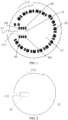
FIG. 1 shows a schematic structural diagram of a light board structure according to Embodiment 2 of the present application; -
FIG. 2 shows a schematic structural diagram of a board body according to Embodiment 2 of the present application; -
FIG. 3 shows a schematic structural diagram of a light fixture comprising a light board structure according to Embodiment 3 of the present application; -
FIG. 4 shows a schematic structural diagram of a light fixture comprising a light board structure according to Embodiment 4 of the present application; -
FIG. 5 shows a schematic structural diagram of a light fixture according to Embodiment 6 of the present application; and -
FIG. 6 shows a schematic structural diagram of a board body of the light board structure according to Embodiment 4 of the present application. - The above drawings include the following reference signs:
- 10, board body; 11, collision avoidance area; 111, open slot; 112, collision avoidance notch; 12, installation port; 13, first port; 14, second port; 20, wireless transceiver module; 21, feeder wire; 22, ground wire; 30, light-emitting member; 40, installation cover; 41, installation cavity; 50, lampshade; 60, welding point.
- The present application will be explained in detail below with reference to the accompanying drawings and in conjunction with the embodiments.
- Embodiment 1 of the present application provides a light board structure. The light board structure includes a
board body 10, awireless transceiver module 20 and a light-emittingmember 30. Thewireless transceiver module 20 and the light-emittingmember 30 are both installed on theboard body 10, and thewireless transceiver module 20 has afeeder wire 21 and aground wire 22. Theboard body 10 is provided with acollision avoidance area 11, which runs through theboard body 10 and is disposed to avoid collision with thewireless transceiver module 20 and the light-emittingmember 30; thefeeder wire 21 and theground wire 22 are both positioned on a side of thecollision avoidance area 11; and thecollision avoidance area 11 is configured to emit a radio wave. It should be noted that the side of thecollision avoidance area 11 herein refers to a position surrounding the periphery of thecollision avoidance area 11, and the light-emittingelement 30 herein may be a light bead or an LED light or other component capable of emitting light. - With the light board structure provided in this embodiment, the
board body 10 is provided with thecollision avoidance area 11, and thefeeder wire 21 and theground wire 22 are located on the side the collision avoidance area, such that thefeeder wire 21 and theground wire 22 can conveniently receive and transmit signals by means of thecollision avoidance area 11, to consequently form a crevice antenna or a slot antenna on the light board. In operation, thewireless transceiver module 20 can effectively radiate electromagnetic waves to outer space by means of thecollision avoidance area 11, such that the communication distance of the light board is greatly increased. - Specifically, the
collision avoidance area 11 includes anopen slot 111. Thefeeder wire 21 and theground wire 22 may be both positioned at an end of theopen slot 111; or thefeeder wire 21 and theground wire 22 may be positioned at each side of theopen slot 111, respectively. With both the above two different structural configurations, thefeeder wire 21 and theground 22 can conveniently receive signals by means of theopen slot 111, such that an effective radiation portion of the antenna can be formed to ensure the radiation efficiency of the antenna. - In this embodiment, the
collision avoidance area 11 further includes acollision avoidance notch 112 positioned in an edge of theboard body 10. Thecollision avoidance notch 112 is communicated with theopen slot 111, and theopen slot 111 is positioned between thecollision avoidance notch 112 and thewireless transceiver module 20. In such a structural configuration, the length of thecollision avoidance area 11 can be conveniently increased to improve the radiation efficiency of the antenna in an even better fashion; in addition, the provision of thecollision avoidance notch 112 at the edge of theboard body 10 also facilitates avoiding collision with other devices and routed wires on theboard body 10. - Specifically, the
open slot 111 in the above embodiment is of a strip-shaped slot structure, and thecollision avoidance notch 112 is an arc-shaped notch. In such a structural configuration, the length of thecollision avoidance area 11 can be conveniently increased in an even better fashion on the basis of better avoidance of thewireless transceiver module 20, the light-emittingelement 30 and other structures on theboard body 10, such that the performance of the antenna can be guaranteed better. - In this embodiment, the
board body 10 is of a circular board structure; thewireless transceiver module 20 is disposed in the middle of the circular board structure; theopen slot 111 radially extends along the circular board structure; thecollision avoidance notch 112 is arc-shaped; and thecollision avoidance notch 112 extends along a periphery of the circular board structure. In such a structural configuration, the arrangement position of thecollision avoidance area 11 can be conveniently optimized to increase the length of thecollision avoidance area 11 as much as possible, and also to facilitate processing and manufacturing. It should be noted that "thewireless transceiver module 20 is disposed in the middle of the circular board structure" is not limited to the case where thewireless transceiver module 20 is disposed at a position corresponding to a circle center of the circular board structure, and a position near the circle center may also be involved. - Specifically, in this embodiment, the
collision avoidance notch 112 has a corresponding arc length of L1, and the circular board structure has a perimeter of L2, with L1 ≥ 1/4 L2. In such a structural configuration, the structural layout of theboard body 10 can be further optimized, and the performance of the antenna can also be improved as much as possible while the collision with the components on theboard body 10 is avoided. - In this embodiment, a plurality of light-emitting
members 30 may also be provided; the plurality of light-emittingmembers 30 are annularly disposed on theboard body 10 at interval; and thecollision avoidance notch 112 is disposed around the plurality of light-emittingmembers 30. In such a structural configuration, the structural layout of the components on theboard body 10 and the layout of thecollision avoidance area 11 on theboard body 10 can be conveniently optimized, such that the reasonable layout of the light-emittingelement 30 can be guaranteed, and the length of thecollision avoidance area 11 can be increased as much as possible, thereby improving the performance of the antenna in an even better fashion. - Specifically, in a solution of this embodiment, the light board structure further includes a π-shaped circuit structure, which is installed on the
board body 10. For a small light fixture, due to the limitation of the size of theboard body 10, the resonance point (S11 < -10dB) of a crevice antenna is generally at 2.8-3 GHz, and a resonance is coupled at 2.5 GHz. By means of the adaptive π-shaped circuit structure, the resonance point can be shifted to the frequency band of 2.4-2.5 GHz, which facilitates the use in Wi-Fi, Bluetooth, ZigBee and other communication systems of an ISM frequency band. - In another solution of this embodiment, the
collision avoidance area 11 has a width of b, with 1 mm ≤ b ≤ 3 mm. Specifically, when the value of b is too small, the radiation efficiency of the antenna will be affected; and when the value of b is too large, the structure of theboard body 10 will be affected. By setting the value of b to the above range, both the structure of theboard body 10 and the radiation efficiency of the antenna can be guaranteed. Preferably, b may be selected as 1.5 mm. - Preferably, in a further solution of this embodiment, the light board structure further includes a π-shaped circuit structure, which is installed on the
board body 10; and thecollision avoidance area 11 has a width of b, with 1 mm ≤ b ≤ 3 mm. In such a structural configuration, the structure in this solution can be simultaneously endowed with the advantages of the structures in the above two solutions. - In this embodiment, the
board body 10 may be made of a metal material. Specifically, theboard body 10 may be an aluminum board. A drive board structure is further installed on theboard body 10. The drive board structure includes a radio frequency module. Thecollision avoidance area 11 is also disposed to avoid collision with the drive board structure and the radio frequency module, and by means of thecollision avoidance area 11, the feeding to the radio frequency module can also be facilitated. - As shown in
FIG. 1 and FIG. 2 , Embodiment 2 of the present application provides a light board structure. The light board structure in this embodiment is an improved version based on the light board in Embodiment 1. In this embodiment, theboard body 10 is provided with aninstallation opening 12 communicated with thecollision avoidance area 11, and thewireless transceiver module 20 includes a pin header structure installed within theinstallation opening 12. The pin header structure includes a first pin header and a second pin header, the first pin header forms thefeeder wire 21, and the second pin header forms theground wire 22. Specifically, the first pin header may be disposed as a radio frequency interface, the second pin header may be disposed as a radio frequency reference structure, and the first pin header and the second pin header are positioned at the end of thecollision avoidance area 11 to form a radiation portion of the antenna. In this way, the feeding to an antenna structure with a crevice can also be implemented by means of the first pin header and the second pin header. Compared with other forms of antennas that protrude out of theboard body 10 in the prior art, the antenna structure in this embodiment does not protrude out of theboard body 10 and thus does not block the light-emittingelement 30 on the other side of theboard body 10, such that a light source is prevented from being blocked by the antenna. In this embodiment, since it is unnecessary to dispose an antenna that runs through theboard body 10 and protrudes out of theboard body 10, a light tube is prevented from being blocked by the antenna, such that a smart light bulb has more uniform light distribution and high lighting quality. In addition, in this embodiment, since the self-contained pin header structure of the light board structure is used for thewireless transceiver module 20, it is also unnecessary to arrange an additional structure for forming thewireless transceiver module 20. - Preferably, in this embodiment, the
installation opening 12 is positioned in the end of thecollision avoidance area 11, and both thefeeder wire 21 and theground wire 22 are also positioned at the end of the collision avoidance area. - Specifically, in this embodiment, the light board structure is applicable to light fixtures of a variety of sizes, in particular various small light fixtures. For a small-size light fixture, generally, there is no space on the light board structure in the prior art for the provision of a slot for the protrusion of an antenna structure, and thus, antennas in the form of crossed radiation frequencies can only be used generally in the small-size light fixture in the prior art, which seriously affects the radio frequency performance during actual use.
- However, for the light board structure in this embodiment, as long as the
collision avoidance area 11 is disposed at a position where the collision with the pin header structure, the light-emittingelements 30 and other structures on theboard body 10 is avoided, and the first pin header and the second pin header are positioned at the periphery of thecollision avoidance area 11, the performance of the antenna can be improved, with a gain of 1-2 dBi and an efficiency up to about 30%, and an effective control distance in a complicated indoor communication environment can reach about 40 m, meeting the requirements of various usage scenarios of smart light fixtures. In addition, such an antenna in this embodiment has no other structure except the collision avoidance area 11 (which may be preferably a crevice, and the longer the length of the crevice, the better the performance of the antenna) provided on theboard body 10, such that the production cost of products can be reduced to some extent. - In this embodiment, the pin header structure may include a plurality of pin headers. Specifically, the pin header structure includes eight pin headers, which are arranged in two rows and four columns. The first pin header and the second pin header are both positioned at the same column of the pin head structure. Eight corresponding welding points 60 are respectively provided on each side of the installation opening, with four
welding points 60 positioned at one side of theinstallation opening 12, and the other four welding points positioned at the other side of theinstallation opening 12. The eightwelding points 60 are disposed corresponding to the eight pin headers on a one-to-one basis. The first pin headers selected as the feeder wire and the second pin headers selected as the ground wire are positioned at the same column of the pin header structure; and the first pin headers and the welding points corresponding thereto are welded, and the second pin headers and the welding points corresponding thereto are welded. - Preferably, the first pin headers and the second pin headers may be selectively positioned at one end of the
installation opening 12 away from thecollision avoidance area 11, such that the first and second pin headers can radiate electromagnetic waves by means of both thecollision avoidance area 11 and theinstallation opening 12, thereby improving the capacity of the antenna in an even better fashion. - Specifically, the
collision avoidance area 11 in this embodiment includes anopen slot 111, and the first pin header and the second pin header are positioned at an end of theopen slot 111, respectively. In such a structure, an effective radiation portion of the antenna can be conveniently formed to ensure the radiation efficiency of the antenna. - As shown in
FIG. 3 , Embodiment 3 of the present application provides a light board structure. The light board structure in this embodiment is an improved version based on Embodiment 1. In this embodiment, a lower surface of theboard body 10 is covered with a first aluminum coating layer; theboard body 10 is provided with afirst port 13; thefirst port 13 is positioned at the end of thecollision avoidance area 11 and runs through theboard body 10; and thefeeder wire 21 passes through thefirst port 13 to be connected to the first aluminum coating layer. In such a structural configuration, thefeeder wire 21 can conveniently pass through thefirst port 13 to be in conduction with the first aluminum coating layer on the lower surface of theboard body 10, such that thewireless transceiver module 20 takes the first aluminum coating layer as an antenna for receiving and transmitting radio waves. - As shown in
FIG. 4 andFIG. 6 , Embodiment 4 of the present application provides a light board structure. The light board structure in this embodiment is an improved version based on construction of the light board structure in Embodiment 3. Specifically, in this embodiment, theboard body 10 is further provided with asecond port 14; thesecond port 14 is spaced apart from thefirst port 13; thesecond port 14 is positioned at the end of thecollision avoidance area 11 and runs through theboard body 10; and theground wire 22 passes through thesecond port 14 to be connected to the first aluminum coating layer. In such a structural configuration, the conduction between theground wire 22 and the first aluminum coating layer on the lower surface of theboard body 10 can be facilitated, and here, theboard body 10 having the aluminum coating layer can be equivalent to a PIFA antenna, such that a better performance is achieved for the antenna. - In the above Embodiments 3 and 4, the
wireless transceiver module 20 may be welded above theboard body 10; or, thefeeder wire 21 may be tightened at thefirst port 13 by means of a gasket and a screw; or, thewireless transceiver module 20 may be welded above theboard body 10, and thefeeder wire 21 may be tightened at thefirst port 13 by means of the gasket and the screw. - Preferably, the
wireless transceiver module 20 is welded above theboard body 10, and thefeeder wire 21 is tightened at thefirst port 13 by means of the gasket and the screw, such that the structural layout is improved and optimized to increase the connection and arrangement stability of thefeeder wire 21. Preferably, theground wire 22 may also be tightened at thefirst port 13 by means of a gasket and a screw, in order to increase the connection and arrangement stability of thefeeder wire 22. - In Embodiments 3 and 4, a plurality of light-emitting
members 30 may be provided, and the plurality of light-emittingmembers 30 are annularly arranged. Thecollision avoidance area 11 is positioned within an inner annular ring defined by the plurality of light-emittingmembers 30, and thecollision avoidance area 11 is an arc-shaped collision avoidance slot. Or, in Embodiments 3 and 4, thecollision avoidance area 11 is of a strip-shaped structure, and the length of thecollision avoidance area 11 is half of a wavelength of the radio wave of thewireless transceiver module 20. Or, in Embodiments 3 and 4, a plurality of light-emittingmembers 30 are provided, and the plurality of light-emittingmembers 30 are annularly arranged; thecollision avoidance area 11 is positioned within an inner annular ring defined by the plurality of light-emittingmembers 30, and thecollision avoidance area 11 is an arc-shaped collision avoidance slot; and thecollision avoidance area 11 is of a strip-shaped structure, and the length of thecollision avoidance area 11 is half of a wavelength of the radio wave of thewireless transceiver module 20. - Specifically, a plurality of light-emitting
members 30 are provided, the plurality of light-emittingmembers 30 are annularly arranged, thecollision avoidance area 11 is positioned within an inner annular ring defined by the plurality of light-emittingmembers 30, and thecollision avoidance area 11 is an arc-shaped collision avoidance slot, such that thecollision avoidance area 11 is disposed close to thefeeder wire 21 and theground wire 22, whereby thefeeder wire 21 and theground wire 22 can conveniently receive and transmit signals by means of thecollision avoidance area 11, thereby forming a crevice antenna or slot antenna on the light board structure. In this way, in operation, thewireless transceiver module 20 can more effectively radiate electromagnetic waves to outer space by means of thecollision avoidance area 11, such that the communication distance of the light board structure is greatly increased. - The
collision avoidance area 11 is of the strip-shaped structure, and the length of thecollision avoidance area 11 is half of the wavelength of the radio wave of thewireless transceiver module 20, such that the electromagnetic waves can be more effectively radiated to the outer space by means of thecollision avoidance area 11, and the communication distance of thewireless transceiver module 20 can be more significantly increased. - Embodiment 5 of the present application provides a light board structure. The light board structure in this embodiment is an improved version based on Embodiments 3 and 4. Specifically, the light board structure is installed in the
installation cavity 41; a second aluminum coating layer is installed on the inner wall of theinstallation cavity 41; and the inner wall of theinstallation cavity 41 is connected to theboard body 10, such that the first aluminum coating layer and the second aluminum coating layer are conducted. In such a structural configuration, the heat dissipation of theboard body 10 can be facilitated; and theinstallation cavity 41 and theboard body 10, when conducted, jointly form a PIFA antenna, which significantly increases the equivalent area of the antenna and further improves the wireless gain. - In this embodiment, the resonant frequency of the first aluminum coating layer is 2.4 GHz or 5 GHz; or the resonant frequency of the second aluminum coating layer is 2.4 GHz or 5 GHz; or the resonant frequency of both the first aluminum coating layer and the second aluminum coating layer is 2.4 GHz or 5 GHz. Specifically, by providing the first aluminum coating layer and the second aluminum coating layer with the resonant frequency of 2.4 GHz or 5 GHz, resonance may take place effectively to achieve excellent performance.
- In all the above embodiments, the
board body 10 may be disposed as an aluminum board structure; a drive board structure is installed on theboard body 10 and includes a radio frequency module; the radio frequency module and the light-emittingelements 30 are installed on the same side of theboard body 10; and thecollision avoidance area 11 is also disposed to avoid collision with the drive board. - As shown in
FIG. 5 , Embodiment 6 of the present application provides a light fixture. The light fixture includes aninstallation cover 40 and a light board structure, and theinstallation cover 40 has aninstallation cavity 41. The light board structure is installed within theinstallation cavity 41, and is the light board structure provided as in all the above embodiments. Thecollision avoidance area 11 of the light board structure fits the inner wall of theinstallation cavity 41 to form a collision avoidance channel. In this embodiment, theinstallation cover 40 is also made of a metal material. - Specifically, when the
collision avoidance area 11 includes the strip-shaped slot and the arc-shaped notch, thecollision avoidance area 11 fits the inner wall of the installation slot to form an L-shaped collision avoidance channel. In this way, the length of the collision avoidance channel can be increased as much as possible on one hand, and on the other hand, the feeding is also facilitated by connecting the edge of theboard body 10 to the middle of theboard body 10. - In the field of smart home, smart lights occupy an important position, among which smart light bulbs have been widely used in smart furniture due to their low price, convenience and practicability.
- Since the operating temperature of the light bulb is high, the light board (i.e., the foregoing board body) of the smart light bulb and the
installation cavity 41 are both provided with an aluminum coating layer to facilitate the heat dissipation of the smart light bulb. These aluminum coating layers can stop the propagation of electromagnetic signals. - At present, the smart light bulbs on the market perform wireless communication by means of a wireless transceiver module (which is also the aforementioned wireless transceiver module 20) that is integrated inside a traditional light fixture. The wireless transceiver module is welded on the light board of the smart light bulb, and meanwhile, the light board is notched to allow an antenna to protrude out of the light board. When the antenna protrudes by a small length, the performance of the antenna is greatly reduced due to insufficient clearance around the antenna caused by the enclosure of the surrounding metallic aluminum coating layer, leading to poor signal quality and short communication distance, which seriously affects user's use experience.
- If the length of the antenna s increased, the protruding antenna will block the light bead on the light board to affect the uniform light distribution of the smart light bulb; and under a condition with low light level, an obvious shadow will also be produced under the light due to the blockage of the antenna. Moreover, the smart light bulb per se has a limited volume and is also covered with the
installation cover 40, such that the length of the antenna cannot be increased randomly. - For this purpose, in the present application, the light board of the smart light bulb is taken as an antenna, one or more light-emitting bodies are arranged below the light board, and the exterior of the
installation cavity 41 is provided with a thread, such that the smart light bulb is fixed on a threaded opening in the ceiling. Specifically, in the present application, wireless signals are received and transmitted by means of the aluminum coating layer on the light board of the smart light bulb, and the surface of the light board is provided with the aluminum coating layer for heat dissipation, such that the light board has the effects of both wireless signal reception/transmission and heat dissipation. - Referring to
FIG. 3 , it exhibits a schematic structural diagram of a smart light bulb (which is also the aforementioned light fixture) according to the present application. The smart light bulb includes a light board, aninstallation cavity 41, a wireless transceiver module, and light-emitting bodies installed on the light board. The lower surface of the light board is provided with afirst port 13 running through the light board; thefirst port 13 is approximately in the shape of a round hole; the lower surface of the light board is covered with an aluminum coating layer and is installed with the light-emitting bodies; and the aluminum coating layer on the surface of the light board can help the light-emitting bodies dissipate heat. A wireless transceiver module is disposed above the light board. Afeeder wire 21 extending from the wireless transceiver module passes through thefirst port 13 to come into contact and conduction with the aluminum coating layer on the lower surface of the light board, and thefeeder wire 21 is fixed on thesecond port 14 by means of a screw and a gasket, such that the wireless transceiver module receives and transmits radio waves by taking the light board, coated with the aluminum coating layer, as an antenna. - Referring to
FIG. 4 , in another embodiment of the present application, the light board further includes asecond port 14 running through the light board. Theground wire 22 of wireless transceiver module passes through thesecond port 14 to be connected to the light board, and theground wire 22 is fixed on thesecond port 14 by using a screw and a gasket, and thus is in conduction with the aluminum coating layer on the surface of the light board. At this time, the light board having the aluminum coating layer on the surface may be equivalent to a PIFA antenna, such that a better performance is achieved for the antenna. - It can be understood that the
first port 13 and thesecond port 14 may partially run through the light board, the method for connecting thefeeder wire 21 and theground wire 22 to the light board inFIG. 3 and FIG. 4 may not be limited to the above screw fixation, and a person skilled in the art may conduct thefeeder wire 21 and theground wire 22 to the aluminum coating layer of the light board in any way, except that thefeeder wire 21 and theground wire 21 should not be too close to each other. - In the embodiments shown in
FIG. 3 and FIG. 4 , the surface of theinstallation cavity 41 may also be plated with the aluminum coating layer, such that theinstallation cavity 41 may also be in conduction with the light board to help the light board dissipate heat. Meanwhile, theinstallation cavity 41 and the light board, when conducted, jointly form a PIFA antenna, which significantly increases the equivalent area of the antenna and further improves the wireless gain. - Referring to
FIG. 5 , optionally, a light-permeable lampshade 50 is further installed below the light board of the smart light bulb. Thelampshade 50 can adjust the distribution of light on one hand, and on the other hand, can prevent safety accidents caused by user's direct touch of components inside the smart light bulb. As an improvement to any embodiment inFIG. 3 to FIG. 5 , referring toFIG. 6 , it shows a bottom view of a light board. The light board of the smart light bulb may be provided with a crevice, which runs through the light board to form a crevice or slot antenna on the light board. The crevice may be in the shape of a curved or linear strip, and the length of the crevice is about half the wavelength of the operating frequency of a wireless communication module. In operation, the wireless communication module can effectively radiate electromagnetic waves to outer space by means of the crevice, such that the communication distance of the smart light bulb is greatly increased. - According to the smart light bulb of the present application, it has been verified that resonance may effectively take place at 2.4 GHz by taking the aluminum coating layer of the light board of the light bulb as an antenna, and the performance is excellent. In practical use, the shape of the light board and the thickness of the aluminum coating layer of the light board may be adjusted to adapt to different communication frequencies.
- It can be understood that this solution is explained by taking the most common circular smart light bulb of 2.4 GHz as an example in the present application; it would have been readily conceivable to a person skilled in the art that the wireless communication module of the smart light bulb in the present application may be also based on Bluetooth, Zigbee, SubIG and other wireless communication technologies; and the size and shape of the light board and
installation cavity 41 may be also in other forms, as long as the light board with the surface coated with aluminum can produce resonance at the operating frequency band of the wireless communication module and provide certain bandwidth. The number of light beads included in the smart light bulb may also be defined at one's discretion, and a combination of different numbers of LED light beads or other light-emitting bodies may be used, which have no effect on the implementation of this solution. - In the smart light bulb according to the present application, the antenna protruding downwards is no longer disposed via the light board, such that light is prevented from being blocked by the antenna, and the smart light bulb has more uniform light distribution and high lighting quality. In addition, the aluminum coating layer is used as the antenna for wireless communication in the present application, which reduces the shielding of signals by the
installation cavity 41, and improves the quality of wireless communication signals for the smart light. - Referring
FIG. 1 , it shows a smart light bulb disclosed in an embodiment of the present application. The smart light bulb includes aninstallation cavity 41 and a light board accommodated in theinstallation cavity 41. Theinstallation cavity 41 includes a metal layer. The light board includes a light board body, and a wireless transceiver module and a light-emitting body, which are installed on the light board body. The light board body is provided with an open slot extending from the edge of the light board, and a through hole next to both sides of the open slot. The wireless transceiver module is provided with afeeder wire 21 and aground wire 22, which are connected to the through hole. In another preferred embodiment, the edge of the light board body is further provided with a notched slot, which is communicated with the open slot. The notched slot is defined by the light board and theinstallation cavity 41. That is, after being installed, the light board and theinstallation cavity 41 form a gap. In another preferred embodiment, the length of the notched slot is greater than or equal to a quarter of the perimeter of the light board body. In this embodiment, it has been tested that a remote control distance exceeds 50 m. In another preferred embodiment, the length of the notched slot is greater than or equal to one third of the perimeter of the light board body. It has been tested that the larger the length of the notched slot, the larger the remote control distance. - The light board is provided with an aluminum layer to facilitate heat dissipation. The light board is further provided with the light-emitting body and the wireless transceiver module. The
feeder wire 21 and theground wire 22, which extend from the wireless transceiver module, are communicated with the through hole, i.e., connecting the aluminum layer. In a preferred embodiment, the light board is provided with a plug pin connecting base (which may be the aforementioned pin header structure or other structures) close to the notched slot, and the plug pin connecting base is welded on the light board body. Two sockets, closest to the notched slot, of the pin connecting base are electrically connected to the through hole. Thefeeder wire 21 and theground wire 22 may be plugged in the plug pin connecting base in a plug pin form, thereby realizing the connection with the through hole. - The inner surface of the
installation cavity 41 may be provided with an aluminum layer to help the light-emitting body dissipate heat. - In another embodiment, a light-
permeable lampshade 50 is further installed on the smart light bulb. Thelampshade 50 can adjust the distribution of light on one hand, and on the other hand, can prevent safety accidents caused by user's direct touch of components inside the smart light bulb. - It can be understood that it is readily conceivable to a person skilled in the art that the wireless communication module of the smart light bulb in the present application may be based on Wi-FI, Bluetooth, Zigbee, SubIG and other wireless communication technologies; and the size and shape of the light board and
installation cavity 41 may be also in other forms. - The smart light bulb according to the present application is no longer provided with an antenna protruding by passing through the light board, such that light is prevented from being blocked by the antenna, and the smart light bulb has more uniform light distribution and high lighting quality.
- From the above description, it can be seen that the above embodiments of the present application achieve the following technical effects: a new form of antenna is developed, the protrusion of the antenna can be prevented simply by providing a long enough collision avoidance area on the board body, and the illumination effect is improved.
- It should be noted that the terms used herein are only intended to describe specific embodiments rather than to limit the exemplary embodiments of the present application. As used herein, unless otherwise expressly indicated in the context, a singular form is intended to include a plural form as well. In addition, it should also be understood that the terms "include" and/or "comprise", when used in the specification, indicate existing features, steps, operations, devices, components, and/or combinations thereof.
- Unless otherwise specifically explained, the relative arrangements, numerical expressions and numerical values of the components and steps recited in these embodiments do not limit the scope of the present application. Meanwhile, it should be understood that, for the convenience of description, the dimensions of each part shown in the accompanying drawings are not drawn according to the actual scaling relation. Techniques, methods and devices that are known to a person or ordinary skills in the related art may not be discussed in detail, but should be considered as part of the specification. In all examples shown and discussed herein, any specific value should be construed as illustrative only, rather than limiting. Therefore, other examples of the exemplary embodiments may have different values. It should be noted that like reference numerals and letters refer to like items in the accompanying drawings below. Therefore, once an item is defined in one drawing, it is unnecessary to further discuss this item in subsequent drawings.
- In the description of the present application, it should be understood that the orientational terms such as "front", "back", "upper", "lower", "left", "right", "transverse", "vertical", "perpendicular", "horizontal", "top" and "bottom" indicate orientational or positional relations on the basis of the orientational or positional relations shown in the drawings, which are provided only for the convenience of describing the present application and simplifying the description. Unless otherwise stated on the contrary, these orientational terms do not indicate or imply that the apparatus or element referred to must have a specific orientation or must be constructed and operated in a specific orientation. Therefore, these cannot be understood as limiting the protection scope of the present application. The orientational terms "inside" and "outside" refer to inside and outside relative to the outline of each component itself.
- For the convenience of description, spatially relative terms such as "on", "above", "on the upper surface of ..." and "over" can be used herein to describe a spatial positional relation between a device or feature shown in the drawings and other devices or features. It should be understood that the spatially relative terms are intended to encompass different orientations of a device in use or operation in addition to its orientation depicted in the drawings. For example, if a device in the drawings is inverted, the device described as "on other devices or constructs" or "above other devices or constructs" would be positioned "under other devices or constructs" or "below other devices or constructs". Therefore, the exemplary term "above" may include two orientations, namely "above" and "below". This device may also be oriented in other ways (by 90-degree rotation or at other orientations), and the spatially relative description used herein are interpreted accordingly.
- In addition, it should be noted that the terms such as "first" and "second" are used to define components only for the convenience of distinguishing the corresponding components. Unless otherwise stated, the above terms have no special meanings, and therefore, cannot be understood as limiting the protection scope of the present application.
- Described above are merely preferred embodiments of the present application, which are not intended to limit the present application. Various modifications and variations can be made to the present application for those skilled in the art. Any modification, made within the scope of the present application shall be construed as being included in the protection scope of the present application as defined by the appended claims.
Claims (15)
- A light board structure, comprising:a board body (10), a wireless transceiver module (20) and a light-emitting member (30),wherein the wireless transceiver module (20) and the light-emitting member (30) are installed on the board body (10), and the wireless transceiver module (20) has a feeder wire (21) and a ground wire (22);wherein the board body (10) is provided with a collision avoidance area (11) running through the board body (10) and being disposed to avoid collision with the wireless transceiver module (20) and the light-emitting member (30), the feeder wire (21) and the ground wire (22) are positioned on a side of the collision avoidance area (11), and the collision avoidance area (11) is configured to emit a radio wave;characterised in thata lower surface of the board body (10) is covered with a first aluminum coating layer, the board body (10) is provided with a first port (13), the first port (13) is positioned at an end of the collision avoidance area (11) and runs through the board body (10), and the feeder wire (21) passes through the first port (13) to be connected to the first aluminum coating layer.
- The light board structure according to claim 1, wherein the collision avoidance area (11) comprises an open slot (111), and whereinthe feeder wire (21) and the ground wire (22) are positioned at an end of the open slot (111); orthe feeder wire (21) and the ground wire (22) are positioned at two sides of the open slot (111), respectively.
- The light board structure according to claim 2, wherein the collision avoidance area (11) further comprises:
a collision avoidance notch (112) positioned in an edge of the board body (10), wherein the collision avoidance notch (112) is communicated with the open slot (111), and the open slot (111) is positioned between the collision avoidance notch (112) and the wireless transceiver module (20). - The light board structure according to claim 3, wherein the open slot (111) is of a strip-shaped slot structure, and the collision avoidance notch (112) is an arc-shaped notch.
- The light board structure according to claim 4, wherein the board body (10) is of a circular board structure, the wireless transceiver module (20) is disposed in a middle of the circular board structure, the open slot (111) radially extends along the circular board structure, the collision avoidance notch (112) is arc-shaped, and the collision avoidance notch (112) extends along a periphery of the circular board structure.
- The light board structure according to claim 5, wherein the collision avoidance notch (112) has a corresponding arc length of L1, and the circular board structure has a perimeter of L2, with L1 ≥ 1/4 L2.
- The light board structure according to claim 3, wherein a plurality of the light-emitting members (30) are disposed, the plurality of light-emitting members (30) are annularly disposed on the board body (10) at an interval, and the collision avoidance notch (112) is disposed around the plurality of light-emitting members (30).
- The light board structure according to claim 1, whereinthe light board structure further comprises a π-shaped circuit structure installed on the board body (10); and/orthe collision avoidance area (11) has a width of b, with 1 mm ≤ b ≤ 3 mm.
- The light board structure according to any one of claims 1 to 8, wherein the board body (10) is provided with an installation opening (12) communicated with the collision avoidance area (11), and the wireless transceiver module comprises:
a pin header structure installed within the installation opening (12), wherein the pin header structure comprises a first pin header and a second pin header, the first pin header forms the feeder wire (21), and the second pin header forms the ground wire (22). - The light board structure according to claim 1, wherein the board body (10) is further provided with a second port (14), the second port (14) is spaced apart from the first port (13), the second port (14) is positioned at an end of the collision avoidance area (11) and runs through the board body (10), and the ground wire (22) passes through the second port (14) to be connected to the first aluminum coating layer.
- The light board structure according to claim 1, whereinthe wireless transceiver module (20) is welded above the board body (10); and/orthe feeder wire (21) is tightened at the first port by means of a gasket and a screw.
- The light board structure according to claim 1, wherein a plurality of the light-emitting members (30) are provided, the plurality of light-emitting members (30) are annularly arranged, the collision avoidance area (11) is positioned within an inner annular ring defined by the plurality of light-emitting members (30), and the collision avoidance area (11) is an arc-shaped collision avoidance slot; and/or
the collision avoidance area (11) is of a strip-shaped structure, and a length of the collision avoidance area (11) is a half of a wavelength of the radio wave of the wireless transceiver module (20). - The light board structure according to claim 1, wherein the light board structure is installed in an installation cavity (41), a second aluminum coating layer is installed on an inner wall of the installation cavity (41), and the inner wall of the installation cavity (41) is connected to the board body (10), such that the first aluminum coating layer and the second aluminum coating layer are conducted.
- The light board structure according to claim 13, wherein the first aluminum coating layer and/or the second aluminum coating layer have a resonant frequency of 2.4 GHz or 5 GHz.
- A light fixture, comprising:an installation cover (40) provided with an installation cavity (41); anda light board structure according to any one of claims 1 to 14 installed within the installation cavity (41), wherein the collision avoidance area (11) of the light board structure and the inner wall of the installation cavity (41) fit to form a collision avoidance channel.
Applications Claiming Priority (4)
| Application Number | Priority Date | Filing Date | Title |
|---|---|---|---|
| CN202010596739.9A CN111649246B (en) | 2020-06-28 | 2020-06-28 | Intelligent lamp |
| CN202010923789.3A CN112032687B (en) | 2020-09-04 | 2020-09-04 | Light panels and smart bulbs |
| CN202021922697.5U CN213066041U (en) | 2020-09-04 | 2020-09-04 | Lamp panel and intelligent bulb |
| PCT/CN2021/102503 WO2022001891A1 (en) | 2020-06-28 | 2021-06-25 | Light board structure and light fixture having same |
Publications (4)
| Publication Number | Publication Date |
|---|---|
| EP4174369A1 EP4174369A1 (en) | 2023-05-03 |
| EP4174369A4 EP4174369A4 (en) | 2023-12-20 |
| EP4174369B1 true EP4174369B1 (en) | 2024-08-28 |
| EP4174369B8 EP4174369B8 (en) | 2024-10-09 |
Family
ID=79315108
Family Applications (1)
| Application Number | Title | Priority Date | Filing Date |
|---|---|---|---|
| EP21833384.7A Active EP4174369B8 (en) | 2020-06-28 | 2021-06-25 | Light board structure and light fixture having same |
Country Status (3)
| Country | Link |
|---|---|
| US (1) | US11774079B1 (en) |
| EP (1) | EP4174369B8 (en) |
| WO (1) | WO2022001891A1 (en) |
Citations (1)
| Publication number | Priority date | Publication date | Assignee | Title |
|---|---|---|---|---|
| CN209232951U (en) * | 2018-12-28 | 2019-08-09 | 厦门赢科光电有限公司 | A kind of Anneta module and intelligent lamp |
Family Cites Families (19)
| Publication number | Priority date | Publication date | Assignee | Title |
|---|---|---|---|---|
| TWI329724B (en) * | 2003-09-09 | 2010-09-01 | Koninkl Philips Electronics Nv | Integrated lamp with feedback and wireless control |
| CN201025632Y (en) * | 2006-12-25 | 2008-02-20 | 富港电子(东莞)有限公司 | Integrated Multi-Band Antenna |
| CN102014180A (en) | 2010-11-24 | 2011-04-13 | 惠州Tcl移动通信有限公司 | Built-in FM antenna realization method and mobile phone using same |
| JP2013098764A (en) | 2011-11-01 | 2013-05-20 | Sony Corp | Electronic apparatus |
| CN104136834A (en) | 2012-01-06 | 2014-11-05 | 瑟莫尔解决方案资源有限责任公司 | LED lights with enhanced wireless communication |
| CN103219580A (en) * | 2012-01-18 | 2013-07-24 | 上海腾怡半导体有限公司 | PIFA antenna system |
| CN102610910A (en) | 2012-03-16 | 2012-07-25 | 浙江兆奕科技有限公司 | Built-in antenna assembly |
| KR101360678B1 (en) | 2012-07-23 | 2014-02-10 | 엘지이노텍 주식회사 | Lighting device |
| KR20150114880A (en) * | 2013-02-04 | 2015-10-13 | 갈트로닉스 코포레이션 리미티드 | Lighting device with integrated slot antenna |
| BR112015026526A2 (en) * | 2013-04-23 | 2017-07-25 | Koninklijke Philips Nv | lighting device and luminaire |
| CN203761333U (en) * | 2014-02-25 | 2014-08-06 | 上海斐讯数据通信技术有限公司 | Filtering circuit, antenna circuit and mobile terminal |
| US10405406B2 (en) * | 2016-06-23 | 2019-09-03 | Ideal Industries Lighting Llc | LED lighting device with communications module and antenna |
| JP6861385B2 (en) * | 2017-05-18 | 2021-04-21 | パナソニックIpマネジメント株式会社 | Lighting control device and lighting equipment equipped with this |
| CN208253381U (en) | 2018-05-30 | 2018-12-18 | 浙江意博高科技术有限公司 | A kind of LED garden lamp |
| WO2020172405A1 (en) * | 2019-02-21 | 2020-08-27 | Dialight Corporation | Led lighting assembly with integrated power conversion and digital transceiver |
| CN209726124U (en) * | 2019-04-19 | 2019-12-03 | 上海精运智能科技有限公司 | A kind of WIFI control intelligent bulbs |
| CN112032687B (en) * | 2020-09-04 | 2024-12-20 | 浙江涂鸦智能电子有限公司 | Light panels and smart bulbs |
| CN213066041U (en) * | 2020-09-04 | 2021-04-27 | 浙江涂鸦智能电子有限公司 | Lamp panel and intelligent bulb |
| CN111649246B (en) * | 2020-06-28 | 2023-08-04 | 杭州涂鸦信息技术有限公司 | Intelligent lamp |
-
2021
- 2021-06-25 WO PCT/CN2021/102503 patent/WO2022001891A1/en not_active Ceased
- 2021-06-25 US US18/003,558 patent/US11774079B1/en active Active
- 2021-06-25 EP EP21833384.7A patent/EP4174369B8/en active Active
Patent Citations (1)
| Publication number | Priority date | Publication date | Assignee | Title |
|---|---|---|---|---|
| CN209232951U (en) * | 2018-12-28 | 2019-08-09 | 厦门赢科光电有限公司 | A kind of Anneta module and intelligent lamp |
Also Published As
| Publication number | Publication date |
|---|---|
| US11774079B1 (en) | 2023-10-03 |
| EP4174369B8 (en) | 2024-10-09 |
| US20230332763A1 (en) | 2023-10-19 |
| WO2022001891A1 (en) | 2022-01-06 |
| WO2022001891A9 (en) | 2022-02-17 |
| EP4174369A1 (en) | 2023-05-03 |
| EP4174369A4 (en) | 2023-12-20 |
Similar Documents
| Publication | Publication Date | Title |
|---|---|---|
| EP2962359B1 (en) | A lighting device and luminaire comprising an antenna | |
| EP3033568B1 (en) | A lighting device and luminaire comprising an integrated antenna | |
| CN102804493B (en) | Lighting fixtures with built-in radio frequency antennas | |
| JP6406603B2 (en) | lighting equipment | |
| US20140168020A1 (en) | Antenna combined with lighting device | |
| JP6558626B2 (en) | lighting equipment | |
| EP3590149B1 (en) | Lighting device with slot antenna | |
| US10665949B2 (en) | Lighting-up device and luminaire | |
| CN111649246B (en) | Intelligent lamp | |
| US11774079B1 (en) | Light board structure and light fixture having the same | |
| CN116111344B (en) | Smart lights | |
| TWI826078B (en) | Antenna assembly and communication device with lighting function | |
| CN211650009U (en) | Intelligent lamp | |
| WO2019191925A1 (en) | Cylindrical antenna and application thereof |
Legal Events
| Date | Code | Title | Description |
|---|---|---|---|
| STAA | Information on the status of an ep patent application or granted ep patent |
Free format text: STATUS: THE INTERNATIONAL PUBLICATION HAS BEEN MADE |
|
| PUAI | Public reference made under article 153(3) epc to a published international application that has entered the european phase |
Free format text: ORIGINAL CODE: 0009012 |
|
| STAA | Information on the status of an ep patent application or granted ep patent |
Free format text: STATUS: REQUEST FOR EXAMINATION WAS MADE |
|
| 17P | Request for examination filed |
Effective date: 20230113 |
|
| AK | Designated contracting states |
Kind code of ref document: A1 Designated state(s): AL AT BE BG CH CY CZ DE DK EE ES FI FR GB GR HR HU IE IS IT LI LT LU LV MC MK MT NL NO PL PT RO RS SE SI SK SM TR |
|
| DAV | Request for validation of the european patent (deleted) | ||
| DAX | Request for extension of the european patent (deleted) | ||
| REG | Reference to a national code |
Ref country code: DE Free format text: PREVIOUS MAIN CLASS: F21V0023000000 Ref country code: DE Ref legal event code: R079 Ref document number: 602021018088 Country of ref document: DE Free format text: PREVIOUS MAIN CLASS: F21V0023000000 Ipc: H01Q0001440000 |
|
| A4 | Supplementary search report drawn up and despatched |
Effective date: 20231122 |
|
| RIC1 | Information provided on ipc code assigned before grant |
Ipc: F21Y 115/10 20160101ALN20231116BHEP Ipc: F21Y 103/33 20160101ALN20231116BHEP Ipc: F21K 9/00 20160101ALI20231116BHEP Ipc: F21V 23/04 20060101ALI20231116BHEP Ipc: H05K 1/02 20060101ALI20231116BHEP Ipc: H01Q 13/10 20060101ALI20231116BHEP Ipc: H01Q 1/44 20060101AFI20231116BHEP |
|
| RIC1 | Information provided on ipc code assigned before grant |
Ipc: F21Y 115/10 20160101ALN20240408BHEP Ipc: F21Y 103/33 20160101ALN20240408BHEP Ipc: F21K 9/00 20160101ALI20240408BHEP Ipc: F21V 23/04 20060101ALI20240408BHEP Ipc: H05K 1/02 20060101ALI20240408BHEP Ipc: H01Q 13/10 20060101ALI20240408BHEP Ipc: H01Q 1/44 20060101AFI20240408BHEP |
|
| GRAP | Despatch of communication of intention to grant a patent |
Free format text: ORIGINAL CODE: EPIDOSNIGR1 |
|
| STAA | Information on the status of an ep patent application or granted ep patent |
Free format text: STATUS: GRANT OF PATENT IS INTENDED |
|
| RIC1 | Information provided on ipc code assigned before grant |
Ipc: F21Y 115/10 20160101ALN20240508BHEP Ipc: F21Y 103/33 20160101ALN20240508BHEP Ipc: F21K 9/00 20160101ALI20240508BHEP Ipc: F21V 23/04 20060101ALI20240508BHEP Ipc: H05K 1/02 20060101ALI20240508BHEP Ipc: H01Q 13/10 20060101ALI20240508BHEP Ipc: H01Q 1/44 20060101AFI20240508BHEP |
|
| INTG | Intention to grant announced |
Effective date: 20240528 |
|
| GRAS | Grant fee paid |
Free format text: ORIGINAL CODE: EPIDOSNIGR3 |
|
| GRAA | (expected) grant |
Free format text: ORIGINAL CODE: 0009210 |
|
| STAA | Information on the status of an ep patent application or granted ep patent |
Free format text: STATUS: THE PATENT HAS BEEN GRANTED |
|
| AK | Designated contracting states |
Kind code of ref document: B1 Designated state(s): AL AT BE BG CH CY CZ DE DK EE ES FI FR GB GR HR HU IE IS IT LI LT LU LV MC MK MT NL NO PL PT RO RS SE SI SK SM TR |
|
| REG | Reference to a national code |
Ref country code: CH Ref legal event code: EP |
|
| REG | Reference to a national code |
Ref country code: CH Ref legal event code: PK Free format text: BERICHTIGUNG B8 |
|
| RAP4 | Party data changed (patent owner data changed or rights of a patent transferred) |
Owner name: ZHEJIANG TUYA SMART ELECTRONICS CO., LTD. Owner name: HANGZHOU TUYA INFORMATION TECHNOLOGY CO., LTD. |
|
| REG | Reference to a national code |
Ref country code: DE Ref legal event code: R096 Ref document number: 602021018088 Country of ref document: DE |
|
| REG | Reference to a national code |
Ref country code: IE Ref legal event code: FG4D |
|
| REG | Reference to a national code |
Ref country code: LT Ref legal event code: MG9D |
|
| PG25 | Lapsed in a contracting state [announced via postgrant information from national office to epo] |
Ref country code: NO Free format text: LAPSE BECAUSE OF FAILURE TO SUBMIT A TRANSLATION OF THE DESCRIPTION OR TO PAY THE FEE WITHIN THE PRESCRIBED TIME-LIMIT Effective date: 20241128 |
|
| REG | Reference to a national code |
Ref country code: AT Ref legal event code: MK05 Ref document number: 1719020 Country of ref document: AT Kind code of ref document: T Effective date: 20240828 |
|
| PG25 | Lapsed in a contracting state [announced via postgrant information from national office to epo] |
Ref country code: FI Free format text: LAPSE BECAUSE OF FAILURE TO SUBMIT A TRANSLATION OF THE DESCRIPTION OR TO PAY THE FEE WITHIN THE PRESCRIBED TIME-LIMIT Effective date: 20240828 Ref country code: NL Free format text: LAPSE BECAUSE OF FAILURE TO SUBMIT A TRANSLATION OF THE DESCRIPTION OR TO PAY THE FEE WITHIN THE PRESCRIBED TIME-LIMIT Effective date: 20240828 Ref country code: PL Free format text: LAPSE BECAUSE OF FAILURE TO SUBMIT A TRANSLATION OF THE DESCRIPTION OR TO PAY THE FEE WITHIN THE PRESCRIBED TIME-LIMIT Effective date: 20240828 Ref country code: GR Free format text: LAPSE BECAUSE OF FAILURE TO SUBMIT A TRANSLATION OF THE DESCRIPTION OR TO PAY THE FEE WITHIN THE PRESCRIBED TIME-LIMIT Effective date: 20241129 Ref country code: PT Free format text: LAPSE BECAUSE OF FAILURE TO SUBMIT A TRANSLATION OF THE DESCRIPTION OR TO PAY THE FEE WITHIN THE PRESCRIBED TIME-LIMIT Effective date: 20241230 |
|
| PG25 | Lapsed in a contracting state [announced via postgrant information from national office to epo] |
Ref country code: BG Free format text: LAPSE BECAUSE OF FAILURE TO SUBMIT A TRANSLATION OF THE DESCRIPTION OR TO PAY THE FEE WITHIN THE PRESCRIBED TIME-LIMIT Effective date: 20240828 |
|
| PG25 | Lapsed in a contracting state [announced via postgrant information from national office to epo] |
Ref country code: LV Free format text: LAPSE BECAUSE OF FAILURE TO SUBMIT A TRANSLATION OF THE DESCRIPTION OR TO PAY THE FEE WITHIN THE PRESCRIBED TIME-LIMIT Effective date: 20240828 |
|
| REG | Reference to a national code |
Ref country code: NL Ref legal event code: MP Effective date: 20240828 |
|
| PG25 | Lapsed in a contracting state [announced via postgrant information from national office to epo] |
Ref country code: AT Free format text: LAPSE BECAUSE OF FAILURE TO SUBMIT A TRANSLATION OF THE DESCRIPTION OR TO PAY THE FEE WITHIN THE PRESCRIBED TIME-LIMIT Effective date: 20240828 Ref country code: IS Free format text: LAPSE BECAUSE OF FAILURE TO SUBMIT A TRANSLATION OF THE DESCRIPTION OR TO PAY THE FEE WITHIN THE PRESCRIBED TIME-LIMIT Effective date: 20241228 |
|
| PG25 | Lapsed in a contracting state [announced via postgrant information from national office to epo] |
Ref country code: HR Free format text: LAPSE BECAUSE OF FAILURE TO SUBMIT A TRANSLATION OF THE DESCRIPTION OR TO PAY THE FEE WITHIN THE PRESCRIBED TIME-LIMIT Effective date: 20240828 |
|
| PG25 | Lapsed in a contracting state [announced via postgrant information from national office to epo] |
Ref country code: ES Free format text: LAPSE BECAUSE OF FAILURE TO SUBMIT A TRANSLATION OF THE DESCRIPTION OR TO PAY THE FEE WITHIN THE PRESCRIBED TIME-LIMIT Effective date: 20240828 Ref country code: RS Free format text: LAPSE BECAUSE OF FAILURE TO SUBMIT A TRANSLATION OF THE DESCRIPTION OR TO PAY THE FEE WITHIN THE PRESCRIBED TIME-LIMIT Effective date: 20241128 |
|
| PG25 | Lapsed in a contracting state [announced via postgrant information from national office to epo] |
Ref country code: RS Free format text: LAPSE BECAUSE OF FAILURE TO SUBMIT A TRANSLATION OF THE DESCRIPTION OR TO PAY THE FEE WITHIN THE PRESCRIBED TIME-LIMIT Effective date: 20241128 Ref country code: PT Free format text: LAPSE BECAUSE OF FAILURE TO SUBMIT A TRANSLATION OF THE DESCRIPTION OR TO PAY THE FEE WITHIN THE PRESCRIBED TIME-LIMIT Effective date: 20241230 Ref country code: PL Free format text: LAPSE BECAUSE OF FAILURE TO SUBMIT A TRANSLATION OF THE DESCRIPTION OR TO PAY THE FEE WITHIN THE PRESCRIBED TIME-LIMIT Effective date: 20240828 Ref country code: NO Free format text: LAPSE BECAUSE OF FAILURE TO SUBMIT A TRANSLATION OF THE DESCRIPTION OR TO PAY THE FEE WITHIN THE PRESCRIBED TIME-LIMIT Effective date: 20241128 Ref country code: NL Free format text: LAPSE BECAUSE OF FAILURE TO SUBMIT A TRANSLATION OF THE DESCRIPTION OR TO PAY THE FEE WITHIN THE PRESCRIBED TIME-LIMIT Effective date: 20240828 Ref country code: LV Free format text: LAPSE BECAUSE OF FAILURE TO SUBMIT A TRANSLATION OF THE DESCRIPTION OR TO PAY THE FEE WITHIN THE PRESCRIBED TIME-LIMIT Effective date: 20240828 Ref country code: IS Free format text: LAPSE BECAUSE OF FAILURE TO SUBMIT A TRANSLATION OF THE DESCRIPTION OR TO PAY THE FEE WITHIN THE PRESCRIBED TIME-LIMIT Effective date: 20241228 Ref country code: HR Free format text: LAPSE BECAUSE OF FAILURE TO SUBMIT A TRANSLATION OF THE DESCRIPTION OR TO PAY THE FEE WITHIN THE PRESCRIBED TIME-LIMIT Effective date: 20240828 Ref country code: GR Free format text: LAPSE BECAUSE OF FAILURE TO SUBMIT A TRANSLATION OF THE DESCRIPTION OR TO PAY THE FEE WITHIN THE PRESCRIBED TIME-LIMIT Effective date: 20241129 Ref country code: FI Free format text: LAPSE BECAUSE OF FAILURE TO SUBMIT A TRANSLATION OF THE DESCRIPTION OR TO PAY THE FEE WITHIN THE PRESCRIBED TIME-LIMIT Effective date: 20240828 Ref country code: ES Free format text: LAPSE BECAUSE OF FAILURE TO SUBMIT A TRANSLATION OF THE DESCRIPTION OR TO PAY THE FEE WITHIN THE PRESCRIBED TIME-LIMIT Effective date: 20240828 Ref country code: BG Free format text: LAPSE BECAUSE OF FAILURE TO SUBMIT A TRANSLATION OF THE DESCRIPTION OR TO PAY THE FEE WITHIN THE PRESCRIBED TIME-LIMIT Effective date: 20240828 Ref country code: AT Free format text: LAPSE BECAUSE OF FAILURE TO SUBMIT A TRANSLATION OF THE DESCRIPTION OR TO PAY THE FEE WITHIN THE PRESCRIBED TIME-LIMIT Effective date: 20240828 |
|
| PG25 | Lapsed in a contracting state [announced via postgrant information from national office to epo] |
Ref country code: DK Free format text: LAPSE BECAUSE OF FAILURE TO SUBMIT A TRANSLATION OF THE DESCRIPTION OR TO PAY THE FEE WITHIN THE PRESCRIBED TIME-LIMIT Effective date: 20240828 Ref country code: RO Free format text: LAPSE BECAUSE OF FAILURE TO SUBMIT A TRANSLATION OF THE DESCRIPTION OR TO PAY THE FEE WITHIN THE PRESCRIBED TIME-LIMIT Effective date: 20240828 Ref country code: SM Free format text: LAPSE BECAUSE OF FAILURE TO SUBMIT A TRANSLATION OF THE DESCRIPTION OR TO PAY THE FEE WITHIN THE PRESCRIBED TIME-LIMIT Effective date: 20240828 |
|
| PG25 | Lapsed in a contracting state [announced via postgrant information from national office to epo] |
Ref country code: CZ Free format text: LAPSE BECAUSE OF FAILURE TO SUBMIT A TRANSLATION OF THE DESCRIPTION OR TO PAY THE FEE WITHIN THE PRESCRIBED TIME-LIMIT Effective date: 20240828 |
|
| PG25 | Lapsed in a contracting state [announced via postgrant information from national office to epo] |
Ref country code: SK Free format text: LAPSE BECAUSE OF FAILURE TO SUBMIT A TRANSLATION OF THE DESCRIPTION OR TO PAY THE FEE WITHIN THE PRESCRIBED TIME-LIMIT Effective date: 20240828 |
|
| REG | Reference to a national code |
Ref country code: DE Ref legal event code: R097 Ref document number: 602021018088 Country of ref document: DE |
|
| PLBE | No opposition filed within time limit |
Free format text: ORIGINAL CODE: 0009261 |
|
| STAA | Information on the status of an ep patent application or granted ep patent |
Free format text: STATUS: NO OPPOSITION FILED WITHIN TIME LIMIT |
|
| PGFP | Annual fee paid to national office [announced via postgrant information from national office to epo] |
Ref country code: GB Payment date: 20250621 Year of fee payment: 5 |
|
| PGFP | Annual fee paid to national office [announced via postgrant information from national office to epo] |
Ref country code: FR Payment date: 20250617 Year of fee payment: 5 |
|
| 26N | No opposition filed |
Effective date: 20250530 |
|
| PG25 | Lapsed in a contracting state [announced via postgrant information from national office to epo] |
Ref country code: SE Free format text: LAPSE BECAUSE OF FAILURE TO SUBMIT A TRANSLATION OF THE DESCRIPTION OR TO PAY THE FEE WITHIN THE PRESCRIBED TIME-LIMIT Effective date: 20240828 |
|
| PGFP | Annual fee paid to national office [announced via postgrant information from national office to epo] |
Ref country code: DE Payment date: 20250630 Year of fee payment: 5 |
|
| PGFP | Annual fee paid to national office [announced via postgrant information from national office to epo] |
Ref country code: IT Payment date: 20250627 Year of fee payment: 5 |
|
| REG | Reference to a national code |
Ref country code: CH Ref legal event code: H13 Free format text: ST27 STATUS EVENT CODE: U-0-0-H10-H13 (AS PROVIDED BY THE NATIONAL OFFICE) Effective date: 20260127 |
|
| PG25 | Lapsed in a contracting state [announced via postgrant information from national office to epo] |
Ref country code: MC Free format text: LAPSE BECAUSE OF FAILURE TO SUBMIT A TRANSLATION OF THE DESCRIPTION OR TO PAY THE FEE WITHIN THE PRESCRIBED TIME-LIMIT Effective date: 20240828 |
|
| PG25 | Lapsed in a contracting state [announced via postgrant information from national office to epo] |
Ref country code: LU Free format text: LAPSE BECAUSE OF NON-PAYMENT OF DUE FEES Effective date: 20250625 |
|
| REG | Reference to a national code |
Ref country code: BE Ref legal event code: MM Effective date: 20250630 |
|
| PG25 | Lapsed in a contracting state [announced via postgrant information from national office to epo] |
Ref country code: IE Free format text: LAPSE BECAUSE OF NON-PAYMENT OF DUE FEES Effective date: 20250625 |
|
| PG25 | Lapsed in a contracting state [announced via postgrant information from national office to epo] |
Ref country code: BE Free format text: LAPSE BECAUSE OF NON-PAYMENT OF DUE FEES Effective date: 20250630 |
|
| PG25 | Lapsed in a contracting state [announced via postgrant information from national office to epo] |
Ref country code: CH Free format text: LAPSE BECAUSE OF NON-PAYMENT OF DUE FEES Effective date: 20250630 |