EP4174304A1 - Aircraft propulsion system - Google Patents
Aircraft propulsion system Download PDFInfo
- Publication number
- EP4174304A1 EP4174304A1 EP22196825.8A EP22196825A EP4174304A1 EP 4174304 A1 EP4174304 A1 EP 4174304A1 EP 22196825 A EP22196825 A EP 22196825A EP 4174304 A1 EP4174304 A1 EP 4174304A1
- Authority
- EP
- European Patent Office
- Prior art keywords
- aircraft propulsion
- propulsion system
- fuel cell
- hydrogen
- output
- Prior art date
- Legal status (The legal status is an assumption and is not a legal conclusion. Google has not performed a legal analysis and makes no representation as to the accuracy of the status listed.)
- Granted
Links
Images



Classifications
-
- F—MECHANICAL ENGINEERING; LIGHTING; HEATING; WEAPONS; BLASTING
- F02—COMBUSTION ENGINES; HOT-GAS OR COMBUSTION-PRODUCT ENGINE PLANTS
- F02C—GAS-TURBINE PLANTS; AIR INTAKES FOR JET-PROPULSION PLANTS; CONTROLLING FUEL SUPPLY IN AIR-BREATHING JET-PROPULSION PLANTS
- F02C3/00—Gas-turbine plants characterised by the use of combustion products as the working fluid
- F02C3/20—Gas-turbine plants characterised by the use of combustion products as the working fluid using a special fuel, oxidant, or dilution fluid to generate the combustion products
- F02C3/30—Adding water, steam or other fluids for influencing combustion, e.g. to obtain cleaner exhaust gases
- F02C3/305—Increasing the power, speed, torque or efficiency of a gas turbine or the thrust of a turbojet engine by injecting or adding water, steam or other fluids
-
- B—PERFORMING OPERATIONS; TRANSPORTING
- B64—AIRCRAFT; AVIATION; COSMONAUTICS
- B64D—EQUIPMENT FOR FITTING IN OR TO AIRCRAFT; FLIGHT SUITS; PARACHUTES; ARRANGEMENT OR MOUNTING OF POWER PLANTS OR PROPULSION TRANSMISSIONS IN AIRCRAFT
- B64D27/00—Arrangement or mounting of power plants in aircraft; Aircraft characterised by the type or position of power plants
- B64D27/02—Aircraft characterised by the type or position of power plants
- B64D27/10—Aircraft characterised by the type or position of power plants of gas-turbine type
-
- B—PERFORMING OPERATIONS; TRANSPORTING
- B64—AIRCRAFT; AVIATION; COSMONAUTICS
- B64D—EQUIPMENT FOR FITTING IN OR TO AIRCRAFT; FLIGHT SUITS; PARACHUTES; ARRANGEMENT OR MOUNTING OF POWER PLANTS OR PROPULSION TRANSMISSIONS IN AIRCRAFT
- B64D27/00—Arrangement or mounting of power plants in aircraft; Aircraft characterised by the type or position of power plants
- B64D27/02—Aircraft characterised by the type or position of power plants
- B64D27/30—Aircraft characterised by electric power plants
- B64D27/33—Hybrid electric aircraft
-
- B—PERFORMING OPERATIONS; TRANSPORTING
- B64—AIRCRAFT; AVIATION; COSMONAUTICS
- B64D—EQUIPMENT FOR FITTING IN OR TO AIRCRAFT; FLIGHT SUITS; PARACHUTES; ARRANGEMENT OR MOUNTING OF POWER PLANTS OR PROPULSION TRANSMISSIONS IN AIRCRAFT
- B64D27/00—Arrangement or mounting of power plants in aircraft; Aircraft characterised by the type or position of power plants
- B64D27/02—Aircraft characterised by the type or position of power plants
- B64D27/30—Aircraft characterised by electric power plants
- B64D27/35—Arrangements for on-board electric energy production, distribution, recovery or storage
- B64D27/355—Arrangements for on-board electric energy production, distribution, recovery or storage using fuel cells
-
- B—PERFORMING OPERATIONS; TRANSPORTING
- B64—AIRCRAFT; AVIATION; COSMONAUTICS
- B64D—EQUIPMENT FOR FITTING IN OR TO AIRCRAFT; FLIGHT SUITS; PARACHUTES; ARRANGEMENT OR MOUNTING OF POWER PLANTS OR PROPULSION TRANSMISSIONS IN AIRCRAFT
- B64D33/00—Arrangement in aircraft of power plant parts or auxiliaries not otherwise provided for
- B64D33/08—Arrangement in aircraft of power plant parts or auxiliaries not otherwise provided for of power plant cooling systems
-
- F—MECHANICAL ENGINEERING; LIGHTING; HEATING; WEAPONS; BLASTING
- F02—COMBUSTION ENGINES; HOT-GAS OR COMBUSTION-PRODUCT ENGINE PLANTS
- F02C—GAS-TURBINE PLANTS; AIR INTAKES FOR JET-PROPULSION PLANTS; CONTROLLING FUEL SUPPLY IN AIR-BREATHING JET-PROPULSION PLANTS
- F02C6/00—Plural gas-turbine plants; Combinations of gas-turbine plants with other apparatus; Adaptations of gas-turbine plants for special use
-
- F—MECHANICAL ENGINEERING; LIGHTING; HEATING; WEAPONS; BLASTING
- F02—COMBUSTION ENGINES; HOT-GAS OR COMBUSTION-PRODUCT ENGINE PLANTS
- F02C—GAS-TURBINE PLANTS; AIR INTAKES FOR JET-PROPULSION PLANTS; CONTROLLING FUEL SUPPLY IN AIR-BREATHING JET-PROPULSION PLANTS
- F02C6/00—Plural gas-turbine plants; Combinations of gas-turbine plants with other apparatus; Adaptations of gas-turbine plants for special use
- F02C6/04—Gas-turbine plants providing heated or pressurised working fluid for other apparatus, e.g. without mechanical power output
- F02C6/06—Gas-turbine plants providing heated or pressurised working fluid for other apparatus, e.g. without mechanical power output providing compressed gas
- F02C6/08—Gas-turbine plants providing heated or pressurised working fluid for other apparatus, e.g. without mechanical power output providing compressed gas the gas being bled from the gas-turbine compressor
-
- F—MECHANICAL ENGINEERING; LIGHTING; HEATING; WEAPONS; BLASTING
- F02—COMBUSTION ENGINES; HOT-GAS OR COMBUSTION-PRODUCT ENGINE PLANTS
- F02C—GAS-TURBINE PLANTS; AIR INTAKES FOR JET-PROPULSION PLANTS; CONTROLLING FUEL SUPPLY IN AIR-BREATHING JET-PROPULSION PLANTS
- F02C6/00—Plural gas-turbine plants; Combinations of gas-turbine plants with other apparatus; Adaptations of gas-turbine plants for special use
- F02C6/04—Gas-turbine plants providing heated or pressurised working fluid for other apparatus, e.g. without mechanical power output
- F02C6/10—Gas-turbine plants providing heated or pressurised working fluid for other apparatus, e.g. without mechanical power output supplying working fluid to a user, e.g. a chemical process, which returns working fluid to a turbine of the plant
-
- F—MECHANICAL ENGINEERING; LIGHTING; HEATING; WEAPONS; BLASTING
- F02—COMBUSTION ENGINES; HOT-GAS OR COMBUSTION-PRODUCT ENGINE PLANTS
- F02C—GAS-TURBINE PLANTS; AIR INTAKES FOR JET-PROPULSION PLANTS; CONTROLLING FUEL SUPPLY IN AIR-BREATHING JET-PROPULSION PLANTS
- F02C7/00—Features, components parts, details or accessories, not provided for in, or of interest apart form groups F02C1/00 - F02C6/00; Air intakes for jet-propulsion plants
- F02C7/12—Cooling of plants
- F02C7/14—Cooling of plants of fluids in the plant, e.g. lubricant or fuel
- F02C7/141—Cooling of plants of fluids in the plant, e.g. lubricant or fuel of working fluid
- F02C7/143—Cooling of plants of fluids in the plant, e.g. lubricant or fuel of working fluid before or between the compressor stages
-
- F—MECHANICAL ENGINEERING; LIGHTING; HEATING; WEAPONS; BLASTING
- F02—COMBUSTION ENGINES; HOT-GAS OR COMBUSTION-PRODUCT ENGINE PLANTS
- F02K—JET-PROPULSION PLANTS
- F02K5/00—Plants including an engine, other than a gas turbine, driving a compressor or a ducted fan
-
- H—ELECTRICITY
- H01—ELECTRIC ELEMENTS
- H01M—PROCESSES OR MEANS, e.g. BATTERIES, FOR THE DIRECT CONVERSION OF CHEMICAL ENERGY INTO ELECTRICAL ENERGY
- H01M8/00—Fuel cells; Manufacture thereof
- H01M8/04—Auxiliary arrangements, e.g. for control of pressure or for circulation of fluids
- H01M8/04082—Arrangements for control of reactant parameters, e.g. pressure or concentration
- H01M8/04089—Arrangements for control of reactant parameters, e.g. pressure or concentration of gaseous reactants
- H01M8/04111—Arrangements for control of reactant parameters, e.g. pressure or concentration of gaseous reactants using a compressor turbine assembly
-
- H—ELECTRICITY
- H01—ELECTRIC ELEMENTS
- H01M—PROCESSES OR MEANS, e.g. BATTERIES, FOR THE DIRECT CONVERSION OF CHEMICAL ENERGY INTO ELECTRICAL ENERGY
- H01M8/00—Fuel cells; Manufacture thereof
- H01M8/04—Auxiliary arrangements, e.g. for control of pressure or for circulation of fluids
- H01M8/04082—Arrangements for control of reactant parameters, e.g. pressure or concentration
- H01M8/04089—Arrangements for control of reactant parameters, e.g. pressure or concentration of gaseous reactants
- H01M8/04119—Arrangements for control of reactant parameters, e.g. pressure or concentration of gaseous reactants with simultaneous supply or evacuation of electrolyte; Humidifying or dehumidifying
- H01M8/04126—Humidifying
- H01M8/04141—Humidifying by water containing exhaust gases
-
- H—ELECTRICITY
- H01—ELECTRIC ELEMENTS
- H01M—PROCESSES OR MEANS, e.g. BATTERIES, FOR THE DIRECT CONVERSION OF CHEMICAL ENERGY INTO ELECTRICAL ENERGY
- H01M8/00—Fuel cells; Manufacture thereof
- H01M8/04—Auxiliary arrangements, e.g. for control of pressure or for circulation of fluids
- H01M8/04082—Arrangements for control of reactant parameters, e.g. pressure or concentration
- H01M8/04089—Arrangements for control of reactant parameters, e.g. pressure or concentration of gaseous reactants
- H01M8/04119—Arrangements for control of reactant parameters, e.g. pressure or concentration of gaseous reactants with simultaneous supply or evacuation of electrolyte; Humidifying or dehumidifying
- H01M8/04156—Arrangements for control of reactant parameters, e.g. pressure or concentration of gaseous reactants with simultaneous supply or evacuation of electrolyte; Humidifying or dehumidifying with product water removal
- H01M8/04164—Arrangements for control of reactant parameters, e.g. pressure or concentration of gaseous reactants with simultaneous supply or evacuation of electrolyte; Humidifying or dehumidifying with product water removal by condensers, gas-liquid separators or filters
-
- H—ELECTRICITY
- H01—ELECTRIC ELEMENTS
- H01M—PROCESSES OR MEANS, e.g. BATTERIES, FOR THE DIRECT CONVERSION OF CHEMICAL ENERGY INTO ELECTRICAL ENERGY
- H01M8/00—Fuel cells; Manufacture thereof
- H01M8/04—Auxiliary arrangements, e.g. for control of pressure or for circulation of fluids
- H01M8/04082—Arrangements for control of reactant parameters, e.g. pressure or concentration
- H01M8/04201—Reactant storage and supply, e.g. means for feeding, pipes
-
- H—ELECTRICITY
- H02—GENERATION; CONVERSION OR DISTRIBUTION OF ELECTRIC POWER
- H02K—DYNAMO-ELECTRIC MACHINES
- H02K7/00—Arrangements for handling mechanical energy structurally associated with dynamo-electric machines, e.g. structural association with mechanical driving motors or auxiliary dynamo-electric machines
- H02K7/18—Structural association of electric generators with mechanical driving motors, e.g. with turbines
- H02K7/1807—Rotary generators
- H02K7/1823—Rotary generators structurally associated with turbines or similar engines
-
- B—PERFORMING OPERATIONS; TRANSPORTING
- B64—AIRCRAFT; AVIATION; COSMONAUTICS
- B64D—EQUIPMENT FOR FITTING IN OR TO AIRCRAFT; FLIGHT SUITS; PARACHUTES; ARRANGEMENT OR MOUNTING OF POWER PLANTS OR PROPULSION TRANSMISSIONS IN AIRCRAFT
- B64D27/00—Arrangement or mounting of power plants in aircraft; Aircraft characterised by the type or position of power plants
- B64D27/02—Aircraft characterised by the type or position of power plants
- B64D27/026—Aircraft characterised by the type or position of power plants comprising different types of power plants, e.g. combination of a piston engine and a gas-turbine
-
- F—MECHANICAL ENGINEERING; LIGHTING; HEATING; WEAPONS; BLASTING
- F05—INDEXING SCHEMES RELATING TO ENGINES OR PUMPS IN VARIOUS SUBCLASSES OF CLASSES F01-F04
- F05D—INDEXING SCHEME FOR ASPECTS RELATING TO NON-POSITIVE-DISPLACEMENT MACHINES OR ENGINES, GAS-TURBINES OR JET-PROPULSION PLANTS
- F05D2220/00—Application
- F05D2220/70—Application in combination with
- F05D2220/76—Application in combination with an electrical generator
-
- F—MECHANICAL ENGINEERING; LIGHTING; HEATING; WEAPONS; BLASTING
- F05—INDEXING SCHEMES RELATING TO ENGINES OR PUMPS IN VARIOUS SUBCLASSES OF CLASSES F01-F04
- F05D—INDEXING SCHEME FOR ASPECTS RELATING TO NON-POSITIVE-DISPLACEMENT MACHINES OR ENGINES, GAS-TURBINES OR JET-PROPULSION PLANTS
- F05D2260/00—Function
- F05D2260/20—Heat transfer, e.g. cooling
- F05D2260/211—Heat transfer, e.g. cooling by intercooling, e.g. during a compression cycle
-
- H—ELECTRICITY
- H01—ELECTRIC ELEMENTS
- H01M—PROCESSES OR MEANS, e.g. BATTERIES, FOR THE DIRECT CONVERSION OF CHEMICAL ENERGY INTO ELECTRICAL ENERGY
- H01M2250/00—Fuel cells for particular applications; Specific features of fuel cell system
- H01M2250/20—Fuel cells in motive systems, e.g. vehicle, ship, plane
-
- Y—GENERAL TAGGING OF NEW TECHNOLOGICAL DEVELOPMENTS; GENERAL TAGGING OF CROSS-SECTIONAL TECHNOLOGIES SPANNING OVER SEVERAL SECTIONS OF THE IPC; TECHNICAL SUBJECTS COVERED BY FORMER USPC CROSS-REFERENCE ART COLLECTIONS [XRACs] AND DIGESTS
- Y02—TECHNOLOGIES OR APPLICATIONS FOR MITIGATION OR ADAPTATION AGAINST CLIMATE CHANGE
- Y02T—CLIMATE CHANGE MITIGATION TECHNOLOGIES RELATED TO TRANSPORTATION
- Y02T50/00—Aeronautics or air transport
- Y02T50/60—Efficient propulsion technologies, e.g. for aircraft
-
- Y—GENERAL TAGGING OF NEW TECHNOLOGICAL DEVELOPMENTS; GENERAL TAGGING OF CROSS-SECTIONAL TECHNOLOGIES SPANNING OVER SEVERAL SECTIONS OF THE IPC; TECHNICAL SUBJECTS COVERED BY FORMER USPC CROSS-REFERENCE ART COLLECTIONS [XRACs] AND DIGESTS
- Y02—TECHNOLOGIES OR APPLICATIONS FOR MITIGATION OR ADAPTATION AGAINST CLIMATE CHANGE
- Y02T—CLIMATE CHANGE MITIGATION TECHNOLOGIES RELATED TO TRANSPORTATION
- Y02T90/00—Enabling technologies or technologies with a potential or indirect contribution to GHG emissions mitigation
- Y02T90/40—Application of hydrogen technology to transportation, e.g. using fuel cells
Definitions
- the invention relates to aircraft propulsion systems.
- Gas turbine engines in various forms have been used for aircraft propulsion for several decades.
- a fuel cell system in this application has an air input, as in the case of a proton-exchange (or polymer electrolyte) membrane (PEM) fuel cell system for example.
- PEM polymer electrolyte membrane
- operation of such a fuel cell system generally requires compressed air input, particularly at altitude, in order for sufficient electrical power to be produced, particularly where the fuel cell system is required to provide electrical power for a propulsor comprising an electric motor.
- inclusion of compressor incurs a significant weight penalty in addition to requiring power input to drive the compressor.
- the overall power output/weight performance of such a fuel cell system may preclude its inclusion within certain aircraft.
- an aircraft propulsion system comprises a gas turbine engine arranged to provide propulsive thrust and a fuel cell system having an air input port, the aircraft propulsion system being configured such that air from a compressor of the gas turbine engine is provided to the air input port of the fuel cell system during operation of the aircraft propulsion system.
- compressed air derived from the compressor of the gas turbine engine is provided to the fuel cell system avoiding the need for the fuel cell system to include a dedicated compressor.
- the aircraft propulsion system comprises a condenser coupled to the output port and arranged to condense water vapour in the gaseous output to produce liquid water, the aircraft propulsion system being configured to provide at least a portion of the liquid water to a combustor of the gas turbine engine to effect cooling of the combustor during operation of the aircraft propulsion system.
- the fuel cell system may be proton-exchange membrane (PEM) fuel cell system
- the aircraft propulsion system further comprising a humidifier arranged to receive at least a portion of the liquid water produced by the condenser and to humidify the air from the compressor prior to input thereof to the air input of the PEM fuel cell system.
- a humidifier arranged to receive at least a portion of the liquid water produced by the condenser and to humidify the air from the compressor prior to input thereof to the air input of the PEM fuel cell system.
- water output from the PEM fuel cell system may be used to humidify the PEM fuel cell system.
- the aircraft propulsion system may be arranged such that at least a portion of air output from the condenser provides propulsive thrust in use of the aircraft propulsion system, for example by being provided to the core output flow of the gas turbine engine.
- at least a portion of air output from the condenser may be provided to a turbo-electric generator.
- air from the condenser and hydrogen output from a hydrogen output port of the fuel cell system may be provided to a burner, the burner being arranged to combust the hydrogen and provide resulting combustion products to a turbo-electric generator.
- the air from the compressor may be the principal compressed air output of the compressor section of the gas turbine engine, the compressor section comprising the compressor, at least a portion of air output from the condenser being provided to the combustor in operation of the aircraft propulsion system.
- the air from the compressor may be bleed air from the compressor.
- the aircraft propulsion system may further comprise a heat exchanger disposed between consecutive stages of the gas turbine engine and be arranged such that in operation thereof said gaseous output is provided to the heat exchanger in order to provide cooling of compressed air between said consecutive compressor stages. The efficiency of the compressor stage downstream of the heat exchanger is thereby increased.
- the aircraft propulsion system may be arranged such that gaseous output from the heat exchanger provides propulsive thrust, for example by being provided to the core output flow of the gas turbine engine.
- the gas turbine engine may be a hydrogen-burning gas turbine engine, the fuel cell system being of a type using hydrogen and air as chemical inputs, the aircraft propulsion system further comprising a hydrogen storage system and a conveying system arranged to convey hydrogen from the hydrogen storage system to a hydrogen input port of the fuel cell system and to a combustor of the gas turbine engine.
- the fuel cell system may have a hydrogen output port, the conveying system being arranged to convey hydrogen from the hydrogen output port to the combustor of the gas turbine engine.
- the conveying system may be configured such that hydrogen is conveyed to the combustor of the gas turbine engine exclusively via the fuel cell system.
- an aircraft propulsion system comprises a gas turbine engine arranged to provide propulsive thrust and a fuel cell system which produces gaseous output comprising water vapour at an output port thereof during operation of the aircraft propulsion system, the aircraft propulsion system further comprising a condenser coupled to the output port and arranged to condense water vapour in the gaseous output to produce liquid water, the aircraft propulsion system being configured to provide at least a portion of the liquid water to a combustor of the gas turbine engine to effect cooling of the combustor during operation of the aircraft propulsion system.
- the aircraft propulsion system may comprise an electric motor arranged to drive a propulsor, the fuel cell system being arranged to provide electrical power to the electric motor during operation of the aircraft propulsion system.
- a third aspect of the invention provides an aircraft comprising an aircraft propulsion system according to either the first aspect or the second aspect of the invention.
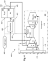
- a first example aircraft propulsion 100 comprises a proton exchange (or polymer electrolyte membrane (PEM) fuel cell system 152 and a hydrogen-burning gas turbine engine 140 each of which are provided with hydrogen fuel from a hydrogen storage system 150 via conveying system 151.
- Hydrogen storage system 150 may be a tank storing gaseous or liquid hydrogen, or some other type of storage system.
- the PEM fuel cell system 152 has a hydrogen input port 153, an air input port 155 and an output port 157 from which gaseous output comprising air and water vapour is produced during operation of the PEM fuel cell system 152.
- the hydrogen-burning gas turbine engine 140 comprises a compressor section 113 comprising low- and high-pressure compressors 110, 112, a turbine section 119 comprising high- and low-pressure turbines 116, 118 , a core output nozzle 120 and a combustor 114.
- the gas turbine engine 140 may form the basis of turbofan, turbojet or turbo-prop engine.
- the principal air output 124 of the compressor section 113 and hydrogen fuel from the hydrogen storage system 150 are provided to the combustor 114.
- Bleed air 122 from the high-pressure compressor 112 is delivered to the air input port 155 of the PEM fuel cell system 152 via a humidifier 166 and hydrogen fuel is delivered to the hydrogen input port 153 of the PEM fuel cell system 152.
- the PEM fuel cell 152 operates in a known manner to provide electrical output power which may be used to drive a propulsor comprising an electric motor, thus contributing to the thrust of the aircraft propulsion system 100, or for other purposes.
- Gaseous output comprising air and water vapour is expelled at the output port 157 of the PEM fuel cell system 152 and provided to a condenser 158 which provides liquid water to a tank 160.
- a pump 164 pumps liquid water from the tank 160 to the humidifier 166 and to the combustor 114.
- the combustor 114 is thereby cooled, reducing NOx emissions and lowering the turbine entry temperature (TET) to the turbine section 119 for a given rate of hydrogen combustion, thus increasing the lifetimes of the turbines 116, 118. (Alternatively, the hydrogen combustion rate may be increased for a given TET).
- Air output from the condenser 158 is provided to the core output nozzle 120 of the gas turbine engine 140, thus contributing to the core output flow of the gas turbine engine 140 and increasing the thrust produced by the aircraft propulsion system 100.
- FIG. 2 shows a second aircraft propulsion system 200 of the invention.
- the aircraft propulsion system 200 comprises a PEM fuel cell system 252 having hydrogen input and output ports 253, 259.
- a conveying system 251 couples a hydrogen fuel storage system 250 to the hydrogen input port 253, and the hydrogen output port 259 to a combustor 214 of gas turbine engine 240.
- hydrogen fuel is provided to the gas turbine engine 240 via the PEM fuel cell system 252.
- Air output from condenser 258 is provided to a turbo-electric generator 280 which generates electrical power, for example for aircraft auxiliary systems or for other purposes.
- Water collected in tank 260 is pumped by pump 264 to humidifier 266 in order to humidify air input to PEM fuel cell system 252 and to cool a combustor 214 of gas turbine engine 240.
- FIG 3 shows a third aircraft propulsion system 300 of the invention.
- Parts of the system 300 which correspond to parts of the system 100 of Figure 1 are labelled with reference numerals which differ by 200 from those labelling the corresponding parts in Figure 1 .
- output air 324 from high-pressure compressor 312 is the principal compressed air output of compressor section 313 and is provided to air input 355 of PEM fuel cell system 352 via humidifier 366.
- a portion of air output from condenser 358 is provided to combustor 314 of gas turbine engine 340, the remainder being provided to core output nozzle 320 of gas turbine engine 340 and contributing to the core output flow of the engine 340.
- Air provided to combustor 314 is therefore provided exclusively via PEM fuel cell system 352.
- FIG 4 shows a fourth aircraft propulsion system 400 of the invention.
- the aircraft propulsion system 400 comprises a hydrogen-burning gas turbine engine 440 and a PEM fuel cell system 452.
- bleed air from high-pressure compressor 412 is provided to air input port 455 of the PEM fuel cell system 452 via humidifier 466, the principal compressed air output of the compressor section 413 being provided to combustor 414.
- Hydrogen fuel from hydrogen storage system 450 is provided to the combustor 414 and to hydrogen input port 453 of PEM fuel cell system 452.
- hydrogen is conveyed by conveying system 451 from hydrogen output port 459 of PEM fuel cell 452 to combustor 414.
- a heat exchanger 413 located between the intermediate- and high-pressure compressors 411, 412 is arranged to receive gaseous output comprising air and water vapour from output port 457 of PEM fuel cell system 452. Air passing from the intermediate compressor 411 to the high-pressure compressor 413 is cooled by the heat exchanger 413, increasing the efficiency of the high-pressure compressor 412. Gaseous output from the heat exchanger is provided to core output nozzle of gas turbine engine 440, contributing to the core output flow of engine 440 and contributing to the thrust produced by the propulsion system 400.
- FIG. 5 shows a fifth example aircraft propulsion system 500.
- the aircraft propulsion system 500 comprises a gas turbine engine 540 arranged to provide propulsive thrust and PEM fuel cell system 552.
- bleed air from high-pressure compressor 512 is provided to air input 555 of PEM fuel cell system 552 via humidifier 566.
- Gaseous output from PEM fuel cell 552 comprises air and water vapour and is provided to condenser 558.
- Condensed water from condenser 558 is provided to tank 560 and pumped by pump 564 to combustor 514 and humidifier 566.
Landscapes
- Engineering & Computer Science (AREA)
- Chemical & Material Sciences (AREA)
- Combustion & Propulsion (AREA)
- Mechanical Engineering (AREA)
- General Engineering & Computer Science (AREA)
- Aviation & Aerospace Engineering (AREA)
- General Chemical & Material Sciences (AREA)
- Chemical Kinetics & Catalysis (AREA)
- Sustainable Development (AREA)
- Manufacturing & Machinery (AREA)
- Sustainable Energy (AREA)
- Life Sciences & Earth Sciences (AREA)
- Electrochemistry (AREA)
- Power Engineering (AREA)
- Fuel Cell (AREA)
Abstract
Description
- The invention relates to aircraft propulsion systems.
- Gas turbine engines in various forms (turbojet, turbofan, turbo-prop etc) have been used for aircraft propulsion for several decades. In some cases, it may be beneficial for an aircraft to be additionally provided with a fuel cell system, either for providing additional thrust in conjunction with a propulsor driven by an electric motor, or for providing electrical power to auxiliary systems of an aircraft. Typically, such a fuel cell system in this application has an air input, as in the case of a proton-exchange (or polymer electrolyte) membrane (PEM) fuel cell system for example. However, operation of such a fuel cell system generally requires compressed air input, particularly at altitude, in order for sufficient electrical power to be produced, particularly where the fuel cell system is required to provide electrical power for a propulsor comprising an electric motor. However, inclusion of compressor incurs a significant weight penalty in addition to requiring power input to drive the compressor. The overall power output/weight performance of such a fuel cell system may preclude its inclusion within certain aircraft.
- According to a first aspect of the present invention, an aircraft propulsion system comprises a gas turbine engine arranged to provide propulsive thrust and a fuel cell system having an air input port, the aircraft propulsion system being configured such that air from a compressor of the gas turbine engine is provided to the air input port of the fuel cell system during operation of the aircraft propulsion system. In operation of the aircraft propulsion system, compressed air derived from the compressor of the gas turbine engine is provided to the fuel cell system avoiding the need for the fuel cell system to include a dedicated compressor.
- If the fuel cell system produces gaseous output comprising water vapour at an output port thereof during operation (as in the case of a PEM fuel cell system for example), preferably the aircraft propulsion system comprises a condenser coupled to the output port and arranged to condense water vapour in the gaseous output to produce liquid water, the aircraft propulsion system being configured to provide at least a portion of the liquid water to a combustor of the gas turbine engine to effect cooling of the combustor during operation of the aircraft propulsion system. By cooling the combustor of the gas turbine engine during operation, NOx emissions of the gas turbine engine are reduced. In addition, the turbine entry temperature of the gas turbine is reduced for a given fuel consumption rate, increasing turbine lifetime. Equivalently, a higher rate of fuel consumption is possible for a given turbine entry temperature.
- The fuel cell system may be proton-exchange membrane (PEM) fuel cell system, the aircraft propulsion system further comprising a humidifier arranged to receive at least a portion of the liquid water produced by the condenser and to humidify the air from the compressor prior to input thereof to the air input of the PEM fuel cell system. Thus, water output from the PEM fuel cell system may be used to humidify the PEM fuel cell system.
- The aircraft propulsion system may be arranged such that at least a portion of air output from the condenser provides propulsive thrust in use of the aircraft propulsion system, for example by being provided to the core output flow of the gas turbine engine. Alternatively, at least a portion of air output from the condenser may be provided to a turbo-electric generator. Alternatively, air from the condenser and hydrogen output from a hydrogen output port of the fuel cell system may be provided to a burner, the burner being arranged to combust the hydrogen and provide resulting combustion products to a turbo-electric generator.
- The air from the compressor may be the principal compressed air output of the compressor section of the gas turbine engine, the compressor section comprising the compressor, at least a portion of air output from the condenser being provided to the combustor in operation of the aircraft propulsion system.
- The air from the compressor may be bleed air from the compressor. In this case, where the fuel cell system produces gaseous output comprising water vapour at an output port thereof, the aircraft propulsion system may further comprise a heat exchanger disposed between consecutive stages of the gas turbine engine and be arranged such that in operation thereof said gaseous output is provided to the heat exchanger in order to provide cooling of compressed air between said consecutive compressor stages. The efficiency of the compressor stage downstream of the heat exchanger is thereby increased. The aircraft propulsion system may be arranged such that gaseous output from the heat exchanger provides propulsive thrust, for example by being provided to the core output flow of the gas turbine engine.
- The gas turbine engine may be a hydrogen-burning gas turbine engine, the fuel cell system being of a type using hydrogen and air as chemical inputs, the aircraft propulsion system further comprising a hydrogen storage system and a conveying system arranged to convey hydrogen from the hydrogen storage system to a hydrogen input port of the fuel cell system and to a combustor of the gas turbine engine. The fuel cell system may have a hydrogen output port, the conveying system being arranged to convey hydrogen from the hydrogen output port to the combustor of the gas turbine engine. The conveying system may be configured such that hydrogen is conveyed to the combustor of the gas turbine engine exclusively via the fuel cell system.
- According to a second aspect of the invention, an aircraft propulsion system comprises a gas turbine engine arranged to provide propulsive thrust and a fuel cell system which produces gaseous output comprising water vapour at an output port thereof during operation of the aircraft propulsion system, the aircraft propulsion system further comprising a condenser coupled to the output port and arranged to condense water vapour in the gaseous output to produce liquid water, the aircraft propulsion system being configured to provide at least a portion of the liquid water to a combustor of the gas turbine engine to effect cooling of the combustor during operation of the aircraft propulsion system.
- The aircraft propulsion system may comprise an electric motor arranged to drive a propulsor, the fuel cell system being arranged to provide electrical power to the electric motor during operation of the aircraft propulsion system.
- A third aspect of the invention provides an aircraft comprising an aircraft propulsion system according to either the first aspect or the second aspect of the invention.
- Embodiments of the invention are described below by way of example only and with reference to the accompanying drawings in which
Figures 1 to 5 show first to fifth example aircraft propulsion systems of the invention respectively. - Referring to
Figure 1 , a firstexample aircraft propulsion 100 comprises a proton exchange (or polymer electrolyte membrane (PEM)fuel cell system 152 and a hydrogen-burninggas turbine engine 140 each of which are provided with hydrogen fuel from ahydrogen storage system 150 viaconveying system 151.Hydrogen storage system 150 may be a tank storing gaseous or liquid hydrogen, or some other type of storage system. The PEMfuel cell system 152 has ahydrogen input port 153, anair input port 155 and anoutput port 157 from which gaseous output comprising air and water vapour is produced during operation of the PEMfuel cell system 152. The hydrogen-burninggas turbine engine 140 comprises acompressor section 113 comprising low- and high-pressure compressors turbine section 119 comprising high- and low-pressure turbines core output nozzle 120 and acombustor 114. Thegas turbine engine 140 may form the basis of turbofan, turbojet or turbo-prop engine. - In operation of the
aircraft propulsion system 100, theprincipal air output 124 of thecompressor section 113 and hydrogen fuel from thehydrogen storage system 150 are provided to thecombustor 114.Bleed air 122 from the high-pressure compressor 112 is delivered to theair input port 155 of the PEMfuel cell system 152 via ahumidifier 166 and hydrogen fuel is delivered to thehydrogen input port 153 of the PEMfuel cell system 152. ThePEM fuel cell 152 operates in a known manner to provide electrical output power which may be used to drive a propulsor comprising an electric motor, thus contributing to the thrust of theaircraft propulsion system 100, or for other purposes. Gaseous output comprising air and water vapour is expelled at theoutput port 157 of the PEMfuel cell system 152 and provided to acondenser 158 which provides liquid water to atank 160. Apump 164 pumps liquid water from thetank 160 to thehumidifier 166 and to thecombustor 114. Thecombustor 114 is thereby cooled, reducing NOx emissions and lowering the turbine entry temperature (TET) to theturbine section 119 for a given rate of hydrogen combustion, thus increasing the lifetimes of theturbines condenser 158 is provided to thecore output nozzle 120 of thegas turbine engine 140, thus contributing to the core output flow of thegas turbine engine 140 and increasing the thrust produced by theaircraft propulsion system 100. -
Figure 2 shows a secondaircraft propulsion system 200 of the invention. Parts of thesystem 200 which correspond to parts of thesystem 100 ofFigure 1 are labelled with reference numerals which differ by 100 from those labelling the corresponding parts inFigure 1 . Theaircraft propulsion system 200 comprises a PEMfuel cell system 252 having hydrogen input andoutput ports conveying system 251 couples a hydrogenfuel storage system 250 to thehydrogen input port 253, and thehydrogen output port 259 to acombustor 214 ofgas turbine engine 240. Thus, hydrogen fuel is provided to thegas turbine engine 240 via the PEMfuel cell system 252. Air output fromcondenser 258 is provided to a turbo-electric generator 280 which generates electrical power, for example for aircraft auxiliary systems or for other purposes. Water collected intank 260 is pumped bypump 264 tohumidifier 266 in order to humidify air input to PEMfuel cell system 252 and to cool acombustor 214 ofgas turbine engine 240. -
Figure 3 shows a thirdaircraft propulsion system 300 of the invention. Parts of thesystem 300 which correspond to parts of thesystem 100 ofFigure 1 are labelled with reference numerals which differ by 200 from those labelling the corresponding parts inFigure 1 . In theaircraft propulsion system 300,output air 324 from high-pressure compressor 312 is the principal compressed air output ofcompressor section 313 and is provided toair input 355 of PEMfuel cell system 352 viahumidifier 366. A portion of air output fromcondenser 358 is provided tocombustor 314 ofgas turbine engine 340, the remainder being provided tocore output nozzle 320 ofgas turbine engine 340 and contributing to the core output flow of theengine 340. Air provided tocombustor 314 is therefore provided exclusively via PEMfuel cell system 352. -
Figure 4 shows a fourthaircraft propulsion system 400 of the invention. Parts of thesystem 400 which correspond to parts of thesystem 100 ofFigure 1 are labelled with reference numerals which differ by 300 from those labelling the corresponding parts inFigure 1 . Theaircraft propulsion system 400 comprises a hydrogen-burninggas turbine engine 440 and a PEMfuel cell system 452. In operation of theaircraft propulsion system 400, bleed air from high-pressure compressor 412 is provided toair input port 455 of the PEMfuel cell system 452 viahumidifier 466, the principal compressed air output of thecompressor section 413 being provided tocombustor 414. Hydrogen fuel fromhydrogen storage system 450 is provided to thecombustor 414 and tohydrogen input port 453 of PEMfuel cell system 452. Additionally, hydrogen is conveyed by conveyingsystem 451 fromhydrogen output port 459 ofPEM fuel cell 452 tocombustor 414. Aheat exchanger 413 located between the intermediate- and high-pressure compressors 411, 412 is arranged to receive gaseous output comprising air and water vapour fromoutput port 457 of PEMfuel cell system 452. Air passing from the intermediate compressor 411 to the high-pressure compressor 413 is cooled by theheat exchanger 413, increasing the efficiency of the high-pressure compressor 412. Gaseous output from the heat exchanger is provided to core output nozzle ofgas turbine engine 440, contributing to the core output flow ofengine 440 and contributing to the thrust produced by thepropulsion system 400. -
Figure 5 shows a fifth exampleaircraft propulsion system 500. Parts of thesystem 500 which correspond to parts of thesystem 100 ofFigure 1 are labelled with reference numerals which differ by 400 from those labelling the corresponding parts inFigure 1 . Theaircraft propulsion system 500 comprises agas turbine engine 540 arranged to provide propulsive thrust and PEMfuel cell system 552. During operation of thesystem 500, bleed air from high-pressure compressor 512 is provided toair input 555 of PEMfuel cell system 552 viahumidifier 566. Gaseous output fromPEM fuel cell 552 comprises air and water vapour and is provided tocondenser 558. Condensed water fromcondenser 558 is provided totank 560 and pumped bypump 564 tocombustor 514 andhumidifier 566. Air output fromcondenser 558 and hydrogen fuel output fromhydrogen output 559 of the PEMfuel cell system 552 are provided aburner 579. Combustion products output fromburner 579 are provided to a turbine of turbo-electric generator 580 which provides electrical power output, for example for auxiliary systems of an aircraft comprising theaircraft propulsion system 500.
Claims (15)
- An aircraft propulsion system (100; 200; 300; 400; 500) comprising a gas turbine engine (140; 240; 340; 440; 540) arranged to provide propulsive thrust and a fuel cell system (152; 252; 352; 452; 552) having an air input port (155; 255; 355; 455; 555), wherein the aircraft propulsion system is configured such that air from a compressor (112; 212; 312; 412; 512) of the gas turbine engine is provided to the air input port (155; 255; 355; 455; 555) of the fuel cell system during operation of the aircraft propulsion system.
- An aircraft propulsion (100; 200; 300; 500) system according to claim 1 wherein in operation thereof the fuel cell system (152; 252; 352; 552) produces gaseous output comprising water vapour at an output port (157; 257; 357; 557) of the fuel cell system, the aircraft propulsion system comprising a condenser (158; 258; 358; 558) coupled to the output port and arranged to condense water vapour in the gaseous output to produce liquid water and the aircraft propulsion system being configured to provide at least a portion of the liquid water to a combustor (114; 214; 314; 514) of the gas turbine engine to effect cooling of the combustor during operation of the aircraft propulsion system.
- An aircraft propulsion system according to claim 2 wherein the fuel cell system is a PEM fuel cell system and the aircraft propulsion system further comprises a humidifier (166; 266; 366; 566) arranged to receive at least a portion of the liquid water produced by the condenser and to humidify the air from the compressor prior to input thereof to the air input of the PEM fuel cell system.
- An aircraft propulsion (100; 300) system according to claim 2 or claim 3 and arranged such that at least a portion of air output from the condenser provides propulsive thrust in use of the aircraft propulsion system.
- An aircraft propulsion system according to claim 4 wherein at least a portion of air output from the condenser is provided to the core output flow of the gas turbine engine during operation of the aircraft propulsion system.
- An aircraft propulsion system (200) according to claim 2 or claim 3 comprising a turbo-electric generator (280), the aircraft propulsion system being configured such that at least a portion of air output from the condenser (266) is provided to the turbo-electric generator in operation of the aircraft propulsion system.
- An aircraft propulsion system (500) according to claim 2 or claim 3 comprising a burner (579) and a turbo-electric generator (580), the burner being arranged to receive air from the condenser (558) and hydrogen from a hydrogen output port (559) of the fuel cell system (552) and to combust the hydrogen and provide resulting combustion products to the turbo-electric generator.
- An aircraft propulsion system (300) according to any of claims 2 to 7 wherein said air from the compressor is the principal compressed air output (324) of the compressor section (313) of the gas turbine engine (340), the compressor section comprising the compressor (312), and wherein at least a portion of air output from the condenser (358) is provided to the combustor (314) in operation of the aircraft propulsion system.
- An aircraft propulsion system (100; 200; 400; 500) according to any of claims 1 to 7 wherein said air from the compressor (112; 212; 412; 512) is bleed air (122; 222; 422; 522) from the compressor.
- An aircraft propulsion system (400) according to claim 9 when dependent on claim 1 comprising a heat exchanger (413) disposed between consecutive compressor stages (411, 412) of the gas turbine engine (440) and wherein in operation of the aircraft propulsion system the fuel cell system (452) produces gaseous output comprising water vapour at an output port (457) thereof, the aircraft propulsion system being arranged such that in operation thereof said gaseous output is provided to the heat exchanger (413) to provide cooling of compressed air between said consecutive compressor stages.
- An aircraft propulsion system (400) according to claim 10 configured such that gaseous output from the heat exchanger provides propulsive thrust during operation of the aircraft propulsion system.
- An aircraft propulsion system (400) according to claim 11 wherein gaseous output from the heat exchanger is provided to the core output flow of the gas turbine engine during operation of the aircraft propulsion system.
- An aircraft propulsion system (100; 200; 300; 400; 500) according any preceding claim wherein the gas turbine engine is a hydrogen-burning gas turbine engine and the fuel cell system has a hydrogen input port (155; 255; 355; 455; 555), the aircraft propulsion system further comprising a hydrogen storage system (150; 250; 350; 450; 550) and a conveying system (151; 251; 351; 451; 551) arranged to convey hydrogen from the hydrogen storage system to the hydrogen input port of the fuel cell system and to a combustor (114; 214; 314; 414; 514) of the gas turbine engine.
- An aircraft propulsion system (200; 400) according to claim 13 wherein the fuel cell system (252; 452) has a hydrogen output port (259; 459) and the conveying system (251; 451) is arranged to convey hydrogen from the hydrogen output port to the combustor of the hydrogen-burning gas turbine engine.
- An aircraft propulsion system (400) according to claim 14 wherein the conveying system (451) is arranged to convey hydrogen to the combustor (414) of the hydrogen-burning gas turbine engine exclusively via the fuel cell system (452).
Priority Applications (1)
| Application Number | Priority Date | Filing Date | Title |
|---|---|---|---|
| EP23184938.1A EP4242440B1 (en) | 2021-10-18 | 2022-09-21 | Aircraft propulsion system |
Applications Claiming Priority (1)
| Application Number | Priority Date | Filing Date | Title |
|---|---|---|---|
| GBGB2114829.1A GB202114829D0 (en) | 2021-10-18 | 2021-10-18 | Aircraft propulsion system |
Related Child Applications (2)
| Application Number | Title | Priority Date | Filing Date |
|---|---|---|---|
| EP23184938.1A Division EP4242440B1 (en) | 2021-10-18 | 2022-09-21 | Aircraft propulsion system |
| EP23184938.1A Division-Into EP4242440B1 (en) | 2021-10-18 | 2022-09-21 | Aircraft propulsion system |
Publications (2)
| Publication Number | Publication Date |
|---|---|
| EP4174304A1 true EP4174304A1 (en) | 2023-05-03 |
| EP4174304B1 EP4174304B1 (en) | 2025-04-30 |
Family
ID=78718430
Family Applications (2)
| Application Number | Title | Priority Date | Filing Date |
|---|---|---|---|
| EP22196825.8A Active EP4174304B1 (en) | 2021-10-18 | 2022-09-21 | Aircraft propulsion system |
| EP23184938.1A Active EP4242440B1 (en) | 2021-10-18 | 2022-09-21 | Aircraft propulsion system |
Family Applications After (1)
| Application Number | Title | Priority Date | Filing Date |
|---|---|---|---|
| EP23184938.1A Active EP4242440B1 (en) | 2021-10-18 | 2022-09-21 | Aircraft propulsion system |
Country Status (3)
| Country | Link |
|---|---|
| US (1) | US12162611B2 (en) |
| EP (2) | EP4174304B1 (en) |
| GB (1) | GB202114829D0 (en) |
Cited By (1)
| Publication number | Priority date | Publication date | Assignee | Title |
|---|---|---|---|---|
| CN120135462A (en) * | 2025-03-10 | 2025-06-13 | 西北工业大学 | A highly compact thermally managed fuel cell jet engine multi-mode split hybrid propulsion system |
Families Citing this family (15)
| Publication number | Priority date | Publication date | Assignee | Title |
|---|---|---|---|---|
| US11542869B2 (en) * | 2021-05-27 | 2023-01-03 | Pratt & Whitney Canada Corp. | Dual cycle intercooled hydrogen engine architecture |
| FR3125799A1 (en) * | 2021-11-10 | 2023-02-03 | Airbus Operations | AUXILIARY POWER UNIT FOR AN AIRCRAFT |
| US20230278714A1 (en) * | 2022-03-02 | 2023-09-07 | General Electric Company | Anti-stall system with a fuel cell |
| US11920515B2 (en) * | 2022-05-13 | 2024-03-05 | Rtx Corporation | Condenser for hydrogen steam injected turbine engine |
| US11898491B1 (en) * | 2022-07-21 | 2024-02-13 | Rtx Corporation | Water pressure and quantity monitoring for hydrogen steam injected and inter-cooled turbine engine |
| US11933217B2 (en) * | 2022-07-21 | 2024-03-19 | Rtx Corporation | Water condition monitoring for hydrogen steam injected and inter-cooled turbine engine |
| EP4456212B1 (en) * | 2023-04-26 | 2026-02-25 | Hamilton Sundstrand Corporation | Power generation system |
| CN116620554B (en) * | 2023-05-17 | 2025-12-16 | 中国航发湖南动力机械研究所 | Hydrogen-burning hybrid vortex-paddle engine |
| FR3155371B1 (en) * | 2023-11-14 | 2026-01-02 | Safran | Propulsion system equipped with a high-temperature fuel cell with optimized integration. |
| CA3258836A1 (en) * | 2023-12-21 | 2025-11-29 | Pratt & Whitney Canada Corp. | Aircraft power plant with electric motor powered by fuel cell |
| DE102024122543A1 (en) * | 2023-12-21 | 2025-06-26 | Airbus Operations Gmbh | ENERGY CONVERSION ARRANGEMENT, ENERGY SYSTEM AND AIRCRAFT COMPRISING SUCH ARRANGEMENT |
| EP4574660A1 (en) * | 2023-12-21 | 2025-06-25 | Airbus Operations GmbH | Energy conversion arrangement, energy system and aircraft comprising same |
| CN118208321A (en) * | 2024-03-21 | 2024-06-18 | 西北工业大学 | Turbine interstage fuel cell combined jet engine |
| FR3160393A1 (en) * | 2024-03-25 | 2025-09-26 | Safran | Aircraft featuring a propulsion system equipped with a fuel cell with regulated thermal power |
| CN120135463B (en) * | 2025-03-10 | 2025-12-12 | 西北工业大学 | Multi-mode split hybrid propulsion system of compact medium-temperature fuel cell jet engine |
Citations (4)
| Publication number | Priority date | Publication date | Assignee | Title |
|---|---|---|---|---|
| US6296957B1 (en) * | 1998-05-15 | 2001-10-02 | Xcellsis Gmbh | Energy supply unit on board an aircraft |
| US20060254255A1 (en) * | 2005-01-25 | 2006-11-16 | Japan Aerospace Exploration Agency | Aircraft propulsion system |
| US20090293494A1 (en) * | 2006-11-29 | 2009-12-03 | Airbus Deutschland Gmbh | Hybrid drive for an aircraft |
| US20110011096A1 (en) * | 2009-07-15 | 2011-01-20 | Rolls-Royce Plc | System for cooling cooling-air in a gas turbine engine |
-
2021
- 2021-10-18 GB GBGB2114829.1A patent/GB202114829D0/en not_active Ceased
-
2022
- 2022-09-21 EP EP22196825.8A patent/EP4174304B1/en active Active
- 2022-09-21 EP EP23184938.1A patent/EP4242440B1/en active Active
- 2022-09-26 US US17/935,269 patent/US12162611B2/en active Active
Patent Citations (4)
| Publication number | Priority date | Publication date | Assignee | Title |
|---|---|---|---|---|
| US6296957B1 (en) * | 1998-05-15 | 2001-10-02 | Xcellsis Gmbh | Energy supply unit on board an aircraft |
| US20060254255A1 (en) * | 2005-01-25 | 2006-11-16 | Japan Aerospace Exploration Agency | Aircraft propulsion system |
| US20090293494A1 (en) * | 2006-11-29 | 2009-12-03 | Airbus Deutschland Gmbh | Hybrid drive for an aircraft |
| US20110011096A1 (en) * | 2009-07-15 | 2011-01-20 | Rolls-Royce Plc | System for cooling cooling-air in a gas turbine engine |
Cited By (1)
| Publication number | Priority date | Publication date | Assignee | Title |
|---|---|---|---|---|
| CN120135462A (en) * | 2025-03-10 | 2025-06-13 | 西北工业大学 | A highly compact thermally managed fuel cell jet engine multi-mode split hybrid propulsion system |
Also Published As
| Publication number | Publication date |
|---|---|
| US12162611B2 (en) | 2024-12-10 |
| GB202114829D0 (en) | 2021-12-01 |
| US20230120297A1 (en) | 2023-04-20 |
| EP4242440B1 (en) | 2024-06-26 |
| EP4174304B1 (en) | 2025-04-30 |
| EP4242440A3 (en) | 2023-11-29 |
| EP4242440A2 (en) | 2023-09-13 |
Similar Documents
| Publication | Publication Date | Title |
|---|---|---|
| US12162611B2 (en) | Aircraft propulsion system | |
| US12037127B2 (en) | Hydrogen-fuelled aircraft power system | |
| US11749818B2 (en) | Multi-stage turbocharging compressor for fuel cell systems | |
| US12215608B2 (en) | Hydrogen-oxygen fueled powerplant with water and heat recovery | |
| EP3904658A1 (en) | Gas turbine engines having cryogenic fuel systems | |
| US20240200494A1 (en) | Semi-closed cycle aero engine with contrail suppression | |
| US20230258126A1 (en) | Hydrogen-oxygen fueled powerplant with water and heat recovery | |
| US20140182264A1 (en) | Aircraft engine systems and methods for operating same | |
| US11542840B2 (en) | Hybrid power generation systems | |
| CN115405424A (en) | Dual cycle intercooling type hydrogen engine architecture | |
| US12479591B2 (en) | System for conditioning fuel for supplying an aircraft turbomachine, aircraft and method of use | |
| US20240026816A1 (en) | Hydrogen-oxygen gas turbine engine | |
| US20230411646A1 (en) | Fuel cell power system for a vehicle | |
| EP2275656A2 (en) | System for cooling cooling-air in a gas turbine engine | |
| US20250389230A1 (en) | Compressor bypass for low altitude operations | |
| RU2376483C1 (en) | Nuclear gas turbine engine with afterburning | |
| US7615304B2 (en) | SOFC systems to power a liquid or gas fuel pumping station | |
| US20250002160A1 (en) | Aircraft comprising a cabin blower system | |
| US12630295B2 (en) | Aircraft power plant with electric motor powered by fuel cell | |
| US12351326B2 (en) | Power generation system comprising a fuel cell | |
| US20250206449A1 (en) | Aircraft power plant with electric motor powered by fuel cell | |
| CN118529258A (en) | Fuel tank inerting system | |
| Campanari et al. | Performance assessment of turbocharged PEM fuel cell systems for civil aircraft onboard power production |
Legal Events
| Date | Code | Title | Description |
|---|---|---|---|
| PUAI | Public reference made under article 153(3) epc to a published international application that has entered the european phase |
Free format text: ORIGINAL CODE: 0009012 |
|
| STAA | Information on the status of an ep patent application or granted ep patent |
Free format text: STATUS: THE APPLICATION HAS BEEN PUBLISHED |
|
| AK | Designated contracting states |
Kind code of ref document: A1 Designated state(s): AL AT BE BG CH CY CZ DE DK EE ES FI FR GB GR HR HU IE IS IT LI LT LU LV MC MK MT NL NO PL PT RO RS SE SI SK SM TR |
|
| STAA | Information on the status of an ep patent application or granted ep patent |
Free format text: STATUS: REQUEST FOR EXAMINATION WAS MADE |
|
| 17P | Request for examination filed |
Effective date: 20230712 |
|
| RBV | Designated contracting states (corrected) |
Designated state(s): AL AT BE BG CH CY CZ DE DK EE ES FI FR GB GR HR HU IE IS IT LI LT LU LV MC MK MT NL NO PL PT RO RS SE SI SK SM TR |
|
| REG | Reference to a national code |
Ref country code: DE Ref legal event code: R079 Free format text: PREVIOUS MAIN CLASS: F02K0003060000 Ref country code: DE Ref legal event code: R079 Ref document number: 602022013829 Country of ref document: DE Free format text: PREVIOUS MAIN CLASS: F02K0003060000 Ipc: F02C0003300000 |
|
| GRAP | Despatch of communication of intention to grant a patent |
Free format text: ORIGINAL CODE: EPIDOSNIGR1 |
|
| STAA | Information on the status of an ep patent application or granted ep patent |
Free format text: STATUS: GRANT OF PATENT IS INTENDED |
|
| RIC1 | Information provided on ipc code assigned before grant |
Ipc: F02K 5/00 20060101ALI20250206BHEP Ipc: F02C 6/10 20060101ALI20250206BHEP Ipc: F02C 3/30 20060101AFI20250206BHEP |
|
| GRAS | Grant fee paid |
Free format text: ORIGINAL CODE: EPIDOSNIGR3 |
|
| GRAA | (expected) grant |
Free format text: ORIGINAL CODE: 0009210 |
|
| STAA | Information on the status of an ep patent application or granted ep patent |
Free format text: STATUS: THE PATENT HAS BEEN GRANTED |
|
| INTG | Intention to grant announced |
Effective date: 20250303 |
|
| P01 | Opt-out of the competence of the unified patent court (upc) registered |
Free format text: CASE NUMBER: APP_12562/2025 Effective date: 20250313 |
|
| AK | Designated contracting states |
Kind code of ref document: B1 Designated state(s): AL AT BE BG CH CY CZ DE DK EE ES FI FR GB GR HR HU IE IS IT LI LT LU LV MC MK MT NL NO PL PT RO RS SE SI SK SM TR |
|
| REG | Reference to a national code |
Ref country code: CH Ref legal event code: EP Ref country code: GB Ref legal event code: FG4D |
|
| REG | Reference to a national code |
Ref country code: IE Ref legal event code: FG4D |
|
| REG | Reference to a national code |
Ref country code: DE Ref legal event code: R096 Ref document number: 602022013829 Country of ref document: DE |
|
| REG | Reference to a national code |
Ref country code: NL Ref legal event code: MP Effective date: 20250430 |
|
| REG | Reference to a national code |
Ref country code: AT Ref legal event code: MK05 Ref document number: 1790209 Country of ref document: AT Kind code of ref document: T Effective date: 20250430 |
|
| PG25 | Lapsed in a contracting state [announced via postgrant information from national office to epo] |
Ref country code: ES Free format text: LAPSE BECAUSE OF FAILURE TO SUBMIT A TRANSLATION OF THE DESCRIPTION OR TO PAY THE FEE WITHIN THE PRESCRIBED TIME-LIMIT Effective date: 20250430 Ref country code: PT Free format text: LAPSE BECAUSE OF FAILURE TO SUBMIT A TRANSLATION OF THE DESCRIPTION OR TO PAY THE FEE WITHIN THE PRESCRIBED TIME-LIMIT Effective date: 20250901 Ref country code: FI Free format text: LAPSE BECAUSE OF FAILURE TO SUBMIT A TRANSLATION OF THE DESCRIPTION OR TO PAY THE FEE WITHIN THE PRESCRIBED TIME-LIMIT Effective date: 20250430 |
|
| PGFP | Annual fee paid to national office [announced via postgrant information from national office to epo] |
Ref country code: DE Payment date: 20250926 Year of fee payment: 4 |
|
| REG | Reference to a national code |
Ref country code: LT Ref legal event code: MG9D |
|
| PG25 | Lapsed in a contracting state [announced via postgrant information from national office to epo] |
Ref country code: NO Free format text: LAPSE BECAUSE OF FAILURE TO SUBMIT A TRANSLATION OF THE DESCRIPTION OR TO PAY THE FEE WITHIN THE PRESCRIBED TIME-LIMIT Effective date: 20250730 Ref country code: GR Free format text: LAPSE BECAUSE OF FAILURE TO SUBMIT A TRANSLATION OF THE DESCRIPTION OR TO PAY THE FEE WITHIN THE PRESCRIBED TIME-LIMIT Effective date: 20250731 |
|
| PG25 | Lapsed in a contracting state [announced via postgrant information from national office to epo] |
Ref country code: NL Free format text: LAPSE BECAUSE OF FAILURE TO SUBMIT A TRANSLATION OF THE DESCRIPTION OR TO PAY THE FEE WITHIN THE PRESCRIBED TIME-LIMIT Effective date: 20250430 Ref country code: PL Free format text: LAPSE BECAUSE OF FAILURE TO SUBMIT A TRANSLATION OF THE DESCRIPTION OR TO PAY THE FEE WITHIN THE PRESCRIBED TIME-LIMIT Effective date: 20250430 |
|
| PG25 | Lapsed in a contracting state [announced via postgrant information from national office to epo] |
Ref country code: BG Free format text: LAPSE BECAUSE OF FAILURE TO SUBMIT A TRANSLATION OF THE DESCRIPTION OR TO PAY THE FEE WITHIN THE PRESCRIBED TIME-LIMIT Effective date: 20250430 |
|
| PG25 | Lapsed in a contracting state [announced via postgrant information from national office to epo] |
Ref country code: HR Free format text: LAPSE BECAUSE OF FAILURE TO SUBMIT A TRANSLATION OF THE DESCRIPTION OR TO PAY THE FEE WITHIN THE PRESCRIBED TIME-LIMIT Effective date: 20250430 |
|
| PG25 | Lapsed in a contracting state [announced via postgrant information from national office to epo] |
Ref country code: AT Free format text: LAPSE BECAUSE OF FAILURE TO SUBMIT A TRANSLATION OF THE DESCRIPTION OR TO PAY THE FEE WITHIN THE PRESCRIBED TIME-LIMIT Effective date: 20250430 |
|
| PGFP | Annual fee paid to national office [announced via postgrant information from national office to epo] |
Ref country code: FR Payment date: 20250925 Year of fee payment: 4 |
|
| PG25 | Lapsed in a contracting state [announced via postgrant information from national office to epo] |
Ref country code: RS Free format text: LAPSE BECAUSE OF FAILURE TO SUBMIT A TRANSLATION OF THE DESCRIPTION OR TO PAY THE FEE WITHIN THE PRESCRIBED TIME-LIMIT Effective date: 20250731 |
|
| PG25 | Lapsed in a contracting state [announced via postgrant information from national office to epo] |
Ref country code: IS Free format text: LAPSE BECAUSE OF FAILURE TO SUBMIT A TRANSLATION OF THE DESCRIPTION OR TO PAY THE FEE WITHIN THE PRESCRIBED TIME-LIMIT Effective date: 20250830 |
|
| PG25 | Lapsed in a contracting state [announced via postgrant information from national office to epo] |
Ref country code: LV Free format text: LAPSE BECAUSE OF FAILURE TO SUBMIT A TRANSLATION OF THE DESCRIPTION OR TO PAY THE FEE WITHIN THE PRESCRIBED TIME-LIMIT Effective date: 20250430 |
|
| PG25 | Lapsed in a contracting state [announced via postgrant information from national office to epo] |
Ref country code: SM Free format text: LAPSE BECAUSE OF FAILURE TO SUBMIT A TRANSLATION OF THE DESCRIPTION OR TO PAY THE FEE WITHIN THE PRESCRIBED TIME-LIMIT Effective date: 20250430 Ref country code: DK Free format text: LAPSE BECAUSE OF FAILURE TO SUBMIT A TRANSLATION OF THE DESCRIPTION OR TO PAY THE FEE WITHIN THE PRESCRIBED TIME-LIMIT Effective date: 20250430 |
|
| PG25 | Lapsed in a contracting state [announced via postgrant information from national office to epo] |
Ref country code: CZ Free format text: LAPSE BECAUSE OF FAILURE TO SUBMIT A TRANSLATION OF THE DESCRIPTION OR TO PAY THE FEE WITHIN THE PRESCRIBED TIME-LIMIT Effective date: 20250430 |
|
| PG25 | Lapsed in a contracting state [announced via postgrant information from national office to epo] |
Ref country code: EE Free format text: LAPSE BECAUSE OF FAILURE TO SUBMIT A TRANSLATION OF THE DESCRIPTION OR TO PAY THE FEE WITHIN THE PRESCRIBED TIME-LIMIT Effective date: 20250430 |
|
| PG25 | Lapsed in a contracting state [announced via postgrant information from national office to epo] |
Ref country code: SK Free format text: LAPSE BECAUSE OF FAILURE TO SUBMIT A TRANSLATION OF THE DESCRIPTION OR TO PAY THE FEE WITHIN THE PRESCRIBED TIME-LIMIT Effective date: 20250430 |
|
| PG25 | Lapsed in a contracting state [announced via postgrant information from national office to epo] |
Ref country code: IT Free format text: LAPSE BECAUSE OF FAILURE TO SUBMIT A TRANSLATION OF THE DESCRIPTION OR TO PAY THE FEE WITHIN THE PRESCRIBED TIME-LIMIT Effective date: 20250430 |
|
| REG | Reference to a national code |
Ref country code: DE Ref legal event code: R097 Ref document number: 602022013829 Country of ref document: DE |
|
| PG25 | Lapsed in a contracting state [announced via postgrant information from national office to epo] |
Ref country code: RO Free format text: LAPSE BECAUSE OF FAILURE TO SUBMIT A TRANSLATION OF THE DESCRIPTION OR TO PAY THE FEE WITHIN THE PRESCRIBED TIME-LIMIT Effective date: 20250430 |
|
| PLBE | No opposition filed within time limit |
Free format text: ORIGINAL CODE: 0009261 |
|
| STAA | Information on the status of an ep patent application or granted ep patent |
Free format text: STATUS: NO OPPOSITION FILED WITHIN TIME LIMIT |
|
| REG | Reference to a national code |
Ref country code: CH Ref legal event code: L10 Free format text: ST27 STATUS EVENT CODE: U-0-0-L10-L00 (AS PROVIDED BY THE NATIONAL OFFICE) Effective date: 20260311 |
|
| 26N | No opposition filed |
Effective date: 20260202 |
|
| REG | Reference to a national code |
Ref country code: CH Ref legal event code: H13 Free format text: ST27 STATUS EVENT CODE: U-0-0-H10-H13 (AS PROVIDED BY THE NATIONAL OFFICE) Effective date: 20260425 |