EP4174303B1 - Cylinder head for internal combustion engine - Google Patents
Cylinder head for internal combustion engine Download PDFInfo
- Publication number
- EP4174303B1 EP4174303B1 EP20942827.5A EP20942827A EP4174303B1 EP 4174303 B1 EP4174303 B1 EP 4174303B1 EP 20942827 A EP20942827 A EP 20942827A EP 4174303 B1 EP4174303 B1 EP 4174303B1
- Authority
- EP
- European Patent Office
- Prior art keywords
- portions
- cylinder head
- cooling water
- disposed
- water jacket
- Prior art date
- Legal status (The legal status is an assumption and is not a legal conclusion. Google has not performed a legal analysis and makes no representation as to the accuracy of the status listed.)
- Active
Links
Images


Classifications
-
- F—MECHANICAL ENGINEERING; LIGHTING; HEATING; WEAPONS; BLASTING
- F02—COMBUSTION ENGINES; HOT-GAS OR COMBUSTION-PRODUCT ENGINE PLANTS
- F02F—CYLINDERS, PISTONS OR CASINGS, FOR COMBUSTION ENGINES; ARRANGEMENTS OF SEALINGS IN COMBUSTION ENGINES
- F02F1/00—Cylinders; Cylinder heads
- F02F1/24—Cylinder heads
- F02F1/26—Cylinder heads having cooling means
- F02F1/36—Cylinder heads having cooling means for liquid cooling
- F02F1/40—Cylinder heads having cooling means for liquid cooling cylinder heads with means for directing, guiding, or distributing liquid stream
-
- F—MECHANICAL ENGINEERING; LIGHTING; HEATING; WEAPONS; BLASTING
- F02—COMBUSTION ENGINES; HOT-GAS OR COMBUSTION-PRODUCT ENGINE PLANTS
- F02F—CYLINDERS, PISTONS OR CASINGS, FOR COMBUSTION ENGINES; ARRANGEMENTS OF SEALINGS IN COMBUSTION ENGINES
- F02F1/00—Cylinders; Cylinder heads
- F02F1/24—Cylinder heads
- F02F1/243—Cylinder heads and inlet or exhaust manifolds integrally cast together
Definitions
- the present invention relates to an internal combustion engine cylinder head.
- Patent Document 1 discloses a cylinder head to which an exhaust pipe mounting flange is fixed by bolts.
- an internal water jacket is formed so as to follow a row of cylinders.
- the cylinder head of Patent Document 1 is formed such that boss portions for attaching the exhaust pipe project into the water jacket.
- JP 2009-115031 A discloses a cooling structure of an engine having a plurality of cylinders arranged in serial along a longitudinal direction of the engine. A vortex generated in a vortex generation area is removed by a cooling water flowing into the vortex generation area from an auxiliary cooling water passage. Thereby, the cooling water is prevented from remaining in the vortex generation area.
- US 2012/192557 A1 discloses a system having an engine and a turbocharger with a turbine receiving exhaust gas from an engine exhaust manifold and an external wastegate valve controlling a bypass exhaust flow past the turbocharger.
- the turbocharger is within a liquid cooled turbine housing with the turbine located in the housing.
- the wastegate valve is located in a separate non-liquid cooled housing.
- Patent Document 1 JP 2000-161129 A
- An internal combustion engine cylinder head comprises a water jacket which discharges cooling water introduced through a plurality of inlet portions in the center through a plurality of outlet portions on the lateral side of the cylinder head to which an exhaust component is attached, a plurality of female threaded portions disposed on the lateral side of the cylinder head, and a plurality of bulging portions which protrude into the water jacket.
- the outlet portions are disposed such that the spacing between those located on either side in the cylinder row direction is wider than the spacing of the inlet portions located on either side in the cylinder row direction.
- the female threaded portions protrude into the water jacket and are disposed between the outlet portions located on either side in the cylinder low direction.
- the bulging portions are disposed to extend from tips of the female threaded portions towards the side where the inlet portions are located.
- the cylinder head can thus guide part of the cooling water flowing in through the inlet portions of the water jacket to the area around the female threaded portions, and strengthen the flow of the cooling water around the female threaded portions. Therefore, the internal combustion engine cylinder head according to the present invention can efficiently cool the female threaded portions to which an exhaust component is attached.
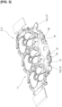
- Figure 1 is a bottom view of a core 1 used in casting an internal combustion engine cylinder head 11 according to the present invention.
- Figure 2 is an oblique view of the core 1 seen from below used in manufacturing the internal combustion engine cylinder head 11 according to the present invention.
- Figure 3 is a perspective view of a first core 2, which forms a first water jacket 12 on the cylinder block side, of the core 1 used in casting the internal combustion engine cylinder head 11 according to the present invention.
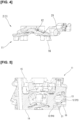
- Figure 4 is a cross-sectional view of the first core 2 along line A-A in Figure 1 .
- Figure 5 is a cross-sectional view of the principal parts of the cylinder head 11 of the internal combustion engine corresponding to the position along line A-A in Figure 1 .
- the internal combustion engine of the present embodiment is an in-line three-cylinder engine, and the core 1 shown in Figures 1 to 4 shows one used in a case in which the internal combustion engine is an in-line three-cylinder engine.
- the cylinder head 11 is described with reference numerals assigned to corresponding positions of the core 1 shown in Figures 1 to 4 .
- locations with two-digit reference numerals among the reference numerals assigned to the core 1 shown in Figures 1 to 4 shall be described as indicating corresponding locations of the cylinder head 11.
- the location assigned reference numeral 12 in Figure 1 is a location corresponding to a first water jacket 12 of the cylinder head 11.
- the depressed portions in the core 1 shown in Figures 1 to 4 are portions which protrude into the cylinder head 11.
- the internal combustion engine cylinder head 11 is made from an aluminum alloy, for example, with an exhaust component (not shown) attached to one lateral surface (one cylinder head lateral surface) side and an intake part (not shown) attached to the other lateral surface (another cylinder head lateral surface) side.
- the cylinder head 11 is configured such that exhaust gas from each of the cylinders merges inside, and the merged exhaust gas flows through the exhaust component.
- the cylinder head 11 has an exhaust gas collection section disposed inside in which the exhaust gas from each of the cylinders merges.
- the exhaust component is an exhaust turbo or manifold catalyst, for example.
- the intake part is an intake manifold, for example.
- the internal combustion engine cylinder head 11 is cast using the core 1 shown in Figures 1 to 4 .
- the core 1 forms a first water jacket 12 and a second water jacket 13 inside the cylinder head 11 and is the collective name for the first core 2 and a second core 3 in the present specification.
- the first core 2 forms the first water jacket 12, serving as a water jacket. As shown in Figure 5 , the first water jacket 12 cools the cylinder block side of the cylinder head 11, which is the lower deck 14 side (bottom side).
- the second core 3 forms the second water jacket 13. As shown in Figure 5 , the second water jacket 13 cools the side (not shown) of the cylinder head 11 which is relatively far away from the cylinder block, which is the upper deck 15 side (top side).
- the first core 2 and the second core 3 are disposed inside the casting mold so as to separate vertically during casting of the cylinder head 11.
- the first water jacket 12 on the lower deck 14 side and the second water jacket 13 on the upper deck 15 side located above the first water jacket 12 are disposed one above the other and spaced apart inside the cylinder head 11.
- the water jackets are disposed in two vertical layers inside the cylinder head 11 by the first water jacket 12 and the second water jacket 13.
- the first water jacket 12 has two first cooling water inlet portions 16 and two first cooling water outlet portions 17.
- the first cooling water inlet portions 16 which serve as the inlet portions are disposed in a straight row along the cylinder row direction of the first water jacket 12 (cylinder head 11).
- the first cooling water inlet portions 16 are located between cylinders of the cylinder head 11.
- the first cooling water inlet portions 16 are disposed in a central location of the first water jacket 12 (cylinder head 11) in a direction at a right angle to the cylinder row.
- the first cooling water inlet portions 16 open in the lower deck 14 of the cylinder head 11 facing the upper deck (not shown) of the cylinder block (not shown). Cooling water flows into the first cooling water inlet portions 16 from cooling water passages (the cylinder block-side water jacket) disposed in the cylinder block outside of that which is shown in the drawings.
- the first cooling water outlet portions 17, serving as the outlet portions are located on one lateral surface side of the cylinder head 11 and are disposed in a straight row along the cylinder row direction.
- the first cooling water outlet portion 17a is disposed on one end of the cylinder head 11 in the cylinder row direction.
- the first cooling water outlet portion 17b is disposed on the other end of the cylinder head 11 in the cylinder row direction.
- the spacing between these two first cooling water outlet portions 17 is disposed so as to be wider than the spacing of the two first cooling water inlet portions 16 along the cylinder row direction.
- the first cooling water outlet portions 17 are disposed such that the spacing between those located on either side in the cylinder row direction is wider than the spacing between the first cooling water inlet portions 16 located on either side in the cylinder row direction.
- the two first cooling water outlet portions 17 are disposed so as to be located on either side of the two first cooling water inlet portions 16 in the cylinder row direction.
- the two first cooling water inlet portions 16 are disposed so as to be located between the two first cooling water outlet portions 17 in the cylinder row direction. That is, the first cooling water inlet portions 16 are disposed so as to be located between the first cooling water outlet portions 17 located on either side in the cylinder row direction.
- the second water jacket 13 has two second cooling water inlet portions 18 and a second cooling water outlet portion (not shown).
- the cooling water which has passed through the first cooling water outlet portions 17 is introduced into the second cooling water inlet portions 18.
- the cooling water which has passed through the first cooling water outlet portions 17 directly below is introduced into the second cooling water inlet portions 18.
- the cooling water which is passed through the first cooling water outlet portions 17a is introduced into the second cooling water inlet portion 18a, and the cooling water which is passed through the first cooling water outlet portion 17b is introduced into the second cooling water inlet portion 18b.
- the cooling water introduced into the second water jacket 13 is discharged to the outside through the second cooling water outlet portions.
- a plurality of female threads for attaching the exhaust component are disposed on one lateral surface side of the cylinder head 11.
- This plurality of female threads is disposed as two boss-type first female threaded portions 19 which are disposed on the lower deck 14 side of the cylinder head 11 and a plurality of boss-type second female threaded portions (not shown) disposed on the upper deck 15 side of the cylinder head 11.
- the female threads for attaching the exhaust component transfer heat from the exhaust component which has become hot during operation of the internal combustion engine.
- the first female threaded portions 19 on the lower deck 14 side near the combustion chamber tend to become hotter than the second female threaded portions on the upper deck 15 side.
- the exhaust component is attached to the cylinder head 11 by bolts (not shown) that are inserted into the female threads.
- the first female threaded portions 19, serving as the female threaded portions are disposed such that the ends are oriented towards the other lateral surface side of the cylinder head 11 and protrude into the first water jacket 12.
- Figures 1 to 3 show the core 1, and therefore the recesses in the core 1 are the first female threaded portions 19 in the cylinder head 11.
- the first female threaded portions 19 are disposed so as to be located inside the two first cooling water outlet portions 17 in the cylinder row direction. In other words, the first female threaded portions 19 are disposed between (inside) the first cooling water outlet portions 17 located on either side in the cylinder row direction.
- the cylinder head 11 has boss-like cylinder head bolt boss portions 20 in locations adjacent the first cooling water inlet portions 16. Note that Figures 1 to 3 show the core 1, and therefore hole sections in the core 1 are the cylinder head bolt boss portions 20 in the cylinder head 11.
- the cylinder head bolt boss portions 20 are located on the cylinder head 11 lateral surface side of the first cooling water inlet portions 16.
- the cylinder head bolt boss portions 20 are such that cylinder head bolts (not shown) for affixing the cylinder head 11 to the cylinder block (not shown) pass through the interior (the inside).
- the cylinder head bolts (not shown) pass through boss holes (not shown) disposed in the cylinder head bolt boss portions 20. These boss holes are machined (bored) after casting of the cylinder head 11, for example.
- the cylinder head 11 has two bulging portions 21 which are adjacent to the first female threaded portions 19 and protrude into the first water jacket 12. Note that Figures 1 , 2 , and 4 show the core 1, and therefore recessed portions of the core 1 are the bulging portions 21 in the cylinder head 11.
- the bulging portions 21 extend from ends of the first female threaded portions 19 toward the side on which the first cooling water inlet portions 16 are located.
- the bulging portions 21 are disposed so as to be located between the cylinder head bolt boss portions 20 and the first female threaded portions 19.
- the bulging portions 21 are disposed such that the first water jacket 12 has a predetermined passage cross-sectional area in the positions of the bulging portions 21. In other words, the upper ends of the bulging portions 21 are not connected to an upper wall surface of the first water jacket 12.
- the cooling water flowing into the first water jacket 12 flows from the first cooling water inlet portions 16 towards the first cooling water outlet portions 17. As indicated by arrows P1, P2, and P3 in Figure 1 , part of the cooling water flowing into the first water jacket 12 flows from the first cooling water inlet portions 16 towards one cylinder head lateral surface side, crosses around the area around the first female threaded portions 19 in the cylinder row direction, and flows to the first cooling water outlet portions 17.
- part of the cooling water flowing into the first water jacket 12 flows from the first cooling water inlet portions 16 towards one cylinder head lateral surface side.
- the cooling water flows inside the first water jacket 12 from the first cooling water inlet portions 16 towards a direction orthogonal to the cylinder row (transverse direction of the cylinder head 11). This is because the first cooling water inlet portions 16 and the first cooling water outlet portions 17 are disposed so as to be offset in the direction orthogonal to the cylinder row.
- the bulging portions 21, which extend from the ends of the first female threaded portions 19 towards the side where the first cooling water inlet portions 16 are disposed, are disposed so as to protrude into the first water jacket 12.
- the cooling water which has bypassed the bulging portions 21 is introduced into the area around the first female threaded portions 19, and the cylinder head 11 can therefore strengthen the flow of the cooling water around the first female threaded portions 19.
- the cylinder head 11, by having the bulging portions 21, can reduce the flow rate of the cooling water flowing through sites where the bulging portions 21 are disposed (cooling water going directly from the first cooling water inlet portions 16 to the first cooling water outlet portions 17 (arrow P4)) and correspondingly increase the flow rate of the cooling water flowing into the area around the first female threaded portions 19 (arrow P2).
- the cylinder head 11 can efficiently cool the first female threaded portions 19 which tend to get hotter than the second female threaded portions.
- the cooling water introduced into the area around the first female threaded portions 19 flows towards the first cooling water outlet portions 17.
- the two first cooling water outlet portions 17 are disposed so as to be located on either side (outside) of the first cooling water inlet portions 16 so as to sandwich all (two) of the first cooling water inlet portions 16 in the cylinder row direction.
- the female threads disposed in the first female threaded portions 19 and the male threads of the bolts inserted into the first female threaded portions 19 may become deformed when the first female threaded portions 19 are in a high temperature state.
- the cylinder head 11 can efficiently cool the first female threaded portions 19 which are more susceptible to high temperatures than the second female threaded portions, and therefore can suppress the tendency of the first female threaded portions 19 to become hot and the tendency of the female threads of the first female threaded portions 19 to deform. Further, the cylinder head 11 can suppress the tendency of the bolts inserted into the first female threaded portions 19 to become hot and the tendency of the male threads of these bolts to deform. In other words, the cylinder head 11 can efficiently cool the first female threaded portions 19 for attachment of the exhaust components and suppress the loosening of bolts in the first female threaded portions 19.
- the number of the first female threaded portions 19 on the lower deck 14 side is not limited to two and may be three or more.
- the number of the bulging portions 21 is not limited to two and may be increased in accordance with the number of the first female threaded portions 19.
- the present invention can be applied to cylinder heads of multicylinder internal combustion engines having three or more cylinders and to cylinder heads in which the number of the first cooling water inlet portions 16 is three or more.
- the present invention can be applied to cylinder heads with one (one layer) internal water jacket.
Landscapes
- Engineering & Computer Science (AREA)
- Chemical & Material Sciences (AREA)
- Combustion & Propulsion (AREA)
- Mechanical Engineering (AREA)
- General Engineering & Computer Science (AREA)
- Cylinder Crankcases Of Internal Combustion Engines (AREA)
Description
- The present invention relates to an internal combustion engine cylinder head.
- For example,
Patent Document 1 discloses a cylinder head to which an exhaust pipe mounting flange is fixed by bolts. In the cylinder head disclosed inPatent Document 1, an internal water jacket is formed so as to follow a row of cylinders. The cylinder head ofPatent Document 1 is formed such that boss portions for attaching the exhaust pipe project into the water jacket. -
JP 2009-115031 A -
US 2012/192557 A1 discloses a system having an engine and a turbocharger with a turbine receiving exhaust gas from an engine exhaust manifold and an external wastegate valve controlling a bypass exhaust flow past the turbocharger. The turbocharger is within a liquid cooled turbine housing with the turbine located in the housing. The wastegate valve is located in a separate non-liquid cooled housing. - However, in the cylinder head disclosed in
Patent Document 1, the flow of cooling water inside the water jacket is uncertain. Therefore, in the cylinder head disclosed inPatent Document 1, the flow of cooling water around the boss portions is weak, and if the cooling water around the boss portions becomes stagnant, there is the risk that the boss portions will be sufficiently cooled. - In other words, in the cylinder head disclosed in
Patent Document 1, when the exhaust pipe becomes hot during operation and the boss portions described above become hot, the threaded portions between the boss portions and the bolts may deform, causing loosening of the bolts. - In other words, there is room for further improvement of the cylinder head in terms of cooling the boss portions for attaching an exhaust component which becomes hot.
- Patent Document 1:
JP 2000-161129 A - An internal combustion engine cylinder head according to the present invention comprises a water jacket which discharges cooling water introduced through a plurality of inlet portions in the center through a plurality of outlet portions on the lateral side of the cylinder head to which an exhaust component is attached, a plurality of female threaded portions disposed on the lateral side of the cylinder head, and a plurality of bulging portions which protrude into the water jacket.
- The outlet portions are disposed such that the spacing between those located on either side in the cylinder row direction is wider than the spacing of the inlet portions located on either side in the cylinder row direction.
- The female threaded portions protrude into the water jacket and are disposed between the outlet portions located on either side in the cylinder low direction.
- The bulging portions are disposed to extend from tips of the female threaded portions towards the side where the inlet portions are located.
- The cylinder head can thus guide part of the cooling water flowing in through the inlet portions of the water jacket to the area around the female threaded portions, and strengthen the flow of the cooling water around the female threaded portions. Therefore, the internal combustion engine cylinder head according to the present invention can efficiently cool the female threaded portions to which an exhaust component is attached.
-
-
Figure 1 is a bottom view of a core used in casting an internal combustion engine cylinder head according to the present invention. -
Figure 2 is a perspective view of a core used in casting the internal combustion engine cylinder head according to the present invention. -
Figure 3 is a perspective view of a first core forming a first water jacket on the cylinder block side. -
Figure 4 is a cross-sectional view of the first core along line A-A inFigure 1 . -
Figure 5 is a cross-sectional view of the principal parts of the internal combustion engine cylinder head according to the present invention. - Embodiments of the present invention are described below in detail with reference to the drawings.
-
Figure 1 is a bottom view of acore 1 used in casting an internal combustionengine cylinder head 11 according to the present invention.Figure 2 is an oblique view of thecore 1 seen from below used in manufacturing the internal combustionengine cylinder head 11 according to the present invention.Figure 3 is a perspective view of afirst core 2, which forms afirst water jacket 12 on the cylinder block side, of thecore 1 used in casting the internal combustionengine cylinder head 11 according to the present invention.Figure 4 is a cross-sectional view of thefirst core 2 along line A-A inFigure 1 .Figure 5 is a cross-sectional view of the principal parts of thecylinder head 11 of the internal combustion engine corresponding to the position along line A-A inFigure 1 . - The internal combustion engine of the present embodiment is an in-line three-cylinder engine, and the
core 1 shown inFigures 1 to 4 shows one used in a case in which the internal combustion engine is an in-line three-cylinder engine. - Also, for the sake of convenience of the description, the
cylinder head 11 is described with reference numerals assigned to corresponding positions of thecore 1 shown inFigures 1 to 4 . For the sake of convenience, locations with two-digit reference numerals among the reference numerals assigned to thecore 1 shown inFigures 1 to 4 shall be described as indicating corresponding locations of thecylinder head 11. For example, the location assignedreference numeral 12 inFigure 1 is a location corresponding to afirst water jacket 12 of thecylinder head 11. The depressed portions in thecore 1 shown inFigures 1 to 4 are portions which protrude into thecylinder head 11. - The internal combustion
engine cylinder head 11 is made from an aluminum alloy, for example, with an exhaust component (not shown) attached to one lateral surface (one cylinder head lateral surface) side and an intake part (not shown) attached to the other lateral surface (another cylinder head lateral surface) side. - The
cylinder head 11 is configured such that exhaust gas from each of the cylinders merges inside, and the merged exhaust gas flows through the exhaust component. In other words, thecylinder head 11 has an exhaust gas collection section disposed inside in which the exhaust gas from each of the cylinders merges. - The exhaust component is an exhaust turbo or manifold catalyst, for example. The intake part is an intake manifold, for example.
- The internal combustion
engine cylinder head 11 is cast using thecore 1 shown inFigures 1 to 4 . Thecore 1 forms afirst water jacket 12 and asecond water jacket 13 inside thecylinder head 11 and is the collective name for thefirst core 2 and asecond core 3 in the present specification. - The
first core 2 forms thefirst water jacket 12, serving as a water jacket. As shown inFigure 5 , thefirst water jacket 12 cools the cylinder block side of thecylinder head 11, which is thelower deck 14 side (bottom side). - The
second core 3 forms thesecond water jacket 13. As shown inFigure 5 , thesecond water jacket 13 cools the side (not shown) of thecylinder head 11 which is relatively far away from the cylinder block, which is theupper deck 15 side (top side). - As shown in
Figure 2 , thefirst core 2 and thesecond core 3 are disposed inside the casting mold so as to separate vertically during casting of thecylinder head 11. In other words, thefirst water jacket 12 on thelower deck 14 side and thesecond water jacket 13 on theupper deck 15 side located above thefirst water jacket 12 are disposed one above the other and spaced apart inside the cylinder head 11.In other words, the water jackets are disposed in two vertical layers inside thecylinder head 11 by thefirst water jacket 12 and thesecond water jacket 13. - The
first water jacket 12 has two first cooling water inletportions 16 and two first coolingwater outlet portions 17. - As shown in
Figures 1 ,2 , and4 , the first cooling water inletportions 16 which serve as the inlet portions are disposed in a straight row along the cylinder row direction of the first water jacket 12 (cylinder head 11). The first coolingwater inlet portions 16 are located between cylinders of thecylinder head 11. The first coolingwater inlet portions 16 are disposed in a central location of the first water jacket 12 (cylinder head 11) in a direction at a right angle to the cylinder row. The first coolingwater inlet portions 16 open in thelower deck 14 of thecylinder head 11 facing the upper deck (not shown) of the cylinder block (not shown). Cooling water flows into the first cooling water inletportions 16 from cooling water passages (the cylinder block-side water jacket) disposed in the cylinder block outside of that which is shown in the drawings. - As shown in
Figures 1 and2 , the first coolingwater outlet portions 17, serving as the outlet portions, are located on one lateral surface side of thecylinder head 11 and are disposed in a straight row along the cylinder row direction. The first coolingwater outlet portion 17a is disposed on one end of thecylinder head 11 in the cylinder row direction. The first coolingwater outlet portion 17b is disposed on the other end of thecylinder head 11 in the cylinder row direction. - The spacing between these two first cooling
water outlet portions 17 is disposed so as to be wider than the spacing of the two first coolingwater inlet portions 16 along the cylinder row direction. In other words, the first coolingwater outlet portions 17 are disposed such that the spacing between those located on either side in the cylinder row direction is wider than the spacing between the first coolingwater inlet portions 16 located on either side in the cylinder row direction. Further, the two first coolingwater outlet portions 17 are disposed so as to be located on either side of the two first coolingwater inlet portions 16 in the cylinder row direction. - In other words, the two first cooling
water inlet portions 16 are disposed so as to be located between the two first coolingwater outlet portions 17 in the cylinder row direction. That is, the first coolingwater inlet portions 16 are disposed so as to be located between the first coolingwater outlet portions 17 located on either side in the cylinder row direction. - The
second water jacket 13 has two second coolingwater inlet portions 18 and a second cooling water outlet portion (not shown). The cooling water which has passed through the first coolingwater outlet portions 17 is introduced into the second coolingwater inlet portions 18. - More specifically, the cooling water which has passed through the first cooling
water outlet portions 17 directly below is introduced into the second coolingwater inlet portions 18. In other words, the cooling water which is passed through the first coolingwater outlet portions 17a is introduced into the second coolingwater inlet portion 18a, and the cooling water which is passed through the first coolingwater outlet portion 17b is introduced into the second coolingwater inlet portion 18b. - The cooling water introduced into the
second water jacket 13 is discharged to the outside through the second cooling water outlet portions. - A plurality of female threads for attaching the exhaust component are disposed on one lateral surface side of the
cylinder head 11. This plurality of female threads is disposed as two boss-type first female threadedportions 19 which are disposed on thelower deck 14 side of thecylinder head 11 and a plurality of boss-type second female threaded portions (not shown) disposed on theupper deck 15 side of thecylinder head 11. - The female threads for attaching the exhaust component transfer heat from the exhaust component which has become hot during operation of the internal combustion engine. In particular, the first female threaded
portions 19 on thelower deck 14 side near the combustion chamber tend to become hotter than the second female threaded portions on theupper deck 15 side. The exhaust component is attached to thecylinder head 11 by bolts (not shown) that are inserted into the female threads. - As shown in
Figures 1 to 3 and5 , the first female threadedportions 19, serving as the female threaded portions, are disposed such that the ends are oriented towards the other lateral surface side of thecylinder head 11 and protrude into thefirst water jacket 12. Note thatFigures 1 to 3 show thecore 1, and therefore the recesses in thecore 1 are the first female threadedportions 19 in thecylinder head 11. - The first female threaded
portions 19 are disposed so as to be located inside the two first coolingwater outlet portions 17 in the cylinder row direction. In other words, the first female threadedportions 19 are disposed between (inside) the first coolingwater outlet portions 17 located on either side in the cylinder row direction. - As shown in
Figures 1 to 3 , thecylinder head 11 has boss-like cylinder headbolt boss portions 20 in locations adjacent the first coolingwater inlet portions 16. Note thatFigures 1 to 3 show thecore 1, and therefore hole sections in thecore 1 are the cylinder headbolt boss portions 20 in thecylinder head 11. - The cylinder head
bolt boss portions 20 are located on thecylinder head 11 lateral surface side of the first coolingwater inlet portions 16. The cylinder headbolt boss portions 20 are such that cylinder head bolts (not shown) for affixing thecylinder head 11 to the cylinder block (not shown) pass through the interior (the inside). The cylinder head bolts (not shown) pass through boss holes (not shown) disposed in the cylinder headbolt boss portions 20. These boss holes are machined (bored) after casting of thecylinder head 11, for example. - As shown in
Figures 1 ,2 ,4, and 5 , thecylinder head 11 has two bulgingportions 21 which are adjacent to the first female threadedportions 19 and protrude into thefirst water jacket 12. Note thatFigures 1 ,2 , and4 show thecore 1, and therefore recessed portions of thecore 1 are the bulgingportions 21 in thecylinder head 11. - The bulging
portions 21 extend from ends of the first female threadedportions 19 toward the side on which the first coolingwater inlet portions 16 are located. The bulgingportions 21 are disposed so as to be located between the cylinder headbolt boss portions 20 and the first female threadedportions 19. - As shown in
Figure 5 , the bulgingportions 21 are disposed such that thefirst water jacket 12 has a predetermined passage cross-sectional area in the positions of the bulgingportions 21. In other words, the upper ends of the bulgingportions 21 are not connected to an upper wall surface of thefirst water jacket 12. - The cooling water flowing into the
first water jacket 12 flows from the first coolingwater inlet portions 16 towards the first coolingwater outlet portions 17. As indicated by arrows P1, P2, and P3 inFigure 1 , part of the cooling water flowing into thefirst water jacket 12 flows from the first coolingwater inlet portions 16 towards one cylinder head lateral surface side, crosses around the area around the first female threadedportions 19 in the cylinder row direction, and flows to the first coolingwater outlet portions 17. - As indicated by arrow P1 in
Figure 1 , part of the cooling water flowing into thefirst water jacket 12 flows from the first coolingwater inlet portions 16 towards one cylinder head lateral surface side. In other words, the cooling water flows inside thefirst water jacket 12 from the first coolingwater inlet portions 16 towards a direction orthogonal to the cylinder row (transverse direction of the cylinder head 11). This is because the first coolingwater inlet portions 16 and the first coolingwater outlet portions 17 are disposed so as to be offset in the direction orthogonal to the cylinder row. - Here, in the
cylinder head 11 according to the present embodiment, the bulgingportions 21, which extend from the ends of the first female threadedportions 19 towards the side where the first coolingwater inlet portions 16 are disposed, are disposed so as to protrude into thefirst water jacket 12. - Therefore, as indicated by arrow P2 in
Figure 1 , the cooling water which has bypassed the bulgingportions 21 is introduced into the area around the first female threadedportions 19, and thecylinder head 11 can therefore strengthen the flow of the cooling water around the first female threadedportions 19. In other words, thecylinder head 11, by having the bulgingportions 21, can reduce the flow rate of the cooling water flowing through sites where the bulgingportions 21 are disposed (cooling water going directly from the first coolingwater inlet portions 16 to the first cooling water outlet portions 17 (arrow P4)) and correspondingly increase the flow rate of the cooling water flowing into the area around the first female threaded portions 19 (arrow P2). Further, thecylinder head 11 can efficiently cool the first female threadedportions 19 which tend to get hotter than the second female threaded portions. - As indicated by arrow P3 in
Figure 1 , the cooling water introduced into the area around the first female threadedportions 19 flows towards the first coolingwater outlet portions 17. This is because the two first coolingwater outlet portions 17 are disposed so as to be located on either side (outside) of the first coolingwater inlet portions 16 so as to sandwich all (two) of the first coolingwater inlet portions 16 in the cylinder row direction. - The female threads disposed in the first female threaded
portions 19 and the male threads of the bolts inserted into the first female threadedportions 19 may become deformed when the first female threadedportions 19 are in a high temperature state. - The
cylinder head 11 can efficiently cool the first female threadedportions 19 which are more susceptible to high temperatures than the second female threaded portions, and therefore can suppress the tendency of the first female threadedportions 19 to become hot and the tendency of the female threads of the first female threadedportions 19 to deform. Further, thecylinder head 11 can suppress the tendency of the bolts inserted into the first female threadedportions 19 to become hot and the tendency of the male threads of these bolts to deform. In other words, thecylinder head 11 can efficiently cool the first female threadedportions 19 for attachment of the exhaust components and suppress the loosening of bolts in the first female threadedportions 19. - An embodiment of the present invention was described above, but the present invention is not limited to the foregoing embodiment.
- For example, the number of the first female threaded
portions 19 on thelower deck 14 side is not limited to two and may be three or more. The number of the bulgingportions 21 is not limited to two and may be increased in accordance with the number of the first female threadedportions 19. - Further, the present invention can be applied to cylinder heads of multicylinder internal combustion engines having three or more cylinders and to cylinder heads in which the number of the first cooling
water inlet portions 16 is three or more. - Moreover, the present invention can be applied to cylinder heads with one (one layer) internal water jacket.
Claims (4)
- An internal combustion engine cylinder head comprising:a water jacket (12) in the cylinder head having a plurality of inlet portions (16) through which cooling water is introduced and a plurality of outlet portions (17) through which the cooling water is discharged;a plurality of female threaded portions (19) having female threads for attaching an exhaust component; anda plurality of bulging portions (21) protruding into the water jacket (12),characterized in thatthe inlet portions (16) are disposed in a central position of the water jacket (12) in a row along a cylinder row direction,the outlet portions (17) are disposed on one lateral surface side of the cylinder head in a row along the cylinder row direction to which the exhaust component is attached, and are disposed such that a spacing between adjacent ones of the outlet portions (17) located on either side in the cylinder row direction is wider than a spacing between the inlet portions (16) located on either side in the cylinder row direction,the female threaded portions (19) are provided to the lateral surface side of the cylinder head, protrude into the water jacket (12), and are disposed between the outlet portions (17) located on either side in the cylinder row direction,the bulging portions (21) are disposed so as to extend from ends of the female threaded portions (19) towards the side where the inlet portions (16) are located, andthe water jacket (12) is disposed around the female threaded portions (19).
- The internal combustion engine cylinder head according to claim 1, wherein
the water jacket (12) is disposed such that part of the cooling water flowing into the water jacket (12) flows from the inlet portions (16) towards one cylinder head lateral surface side, crosses around the area around the female threaded portions (19) in the cylinder row direction, and flows to the cooling water outlet portions (17). - The internal combustion engine cylinder head according to claim 1 or 2, further comprisingcylinder head bolt boss portions in positions adjacent the inlet portions (16), andthe bulging portions (21) being located between the cylinder head bolt boss portions and the female threaded portions (19).
- The internal combustion engine cylinder head of any one of claims 1 to 3, wherein the bulging portions (21) are disposed such that the water jacket (12) has a predetermined passage cross-sectional area in locations of the bulging portions (21).
Applications Claiming Priority (1)
| Application Number | Priority Date | Filing Date | Title |
|---|---|---|---|
| PCT/JP2020/025448 WO2022003753A1 (en) | 2020-06-29 | 2020-06-29 | Cylinder head for internal combustion engine |
Publications (3)
| Publication Number | Publication Date |
|---|---|
| EP4174303A1 EP4174303A1 (en) | 2023-05-03 |
| EP4174303A4 EP4174303A4 (en) | 2023-08-09 |
| EP4174303B1 true EP4174303B1 (en) | 2024-05-01 |
Family
ID=79315735
Family Applications (1)
| Application Number | Title | Priority Date | Filing Date |
|---|---|---|---|
| EP20942827.5A Active EP4174303B1 (en) | 2020-06-29 | 2020-06-29 | Cylinder head for internal combustion engine |
Country Status (5)
| Country | Link |
|---|---|
| US (1) | US11835014B2 (en) |
| EP (1) | EP4174303B1 (en) |
| JP (1) | JP7327671B2 (en) |
| CN (1) | CN115720606B (en) |
| WO (1) | WO2022003753A1 (en) |
Family Cites Families (8)
| Publication number | Priority date | Publication date | Assignee | Title |
|---|---|---|---|---|
| JP3605521B2 (en) | 1998-12-01 | 2004-12-22 | 本田技研工業株式会社 | Cylinder head structure of multi-cylinder engine |
| JP2002070642A (en) | 2000-08-25 | 2002-03-08 | Honda Motor Co Ltd | Multi-cylinder engine cylinder head |
| JP4098712B2 (en) | 2003-12-25 | 2008-06-11 | 本田技研工業株式会社 | Exhaust manifold integrated engine cooling structure |
| JP4983556B2 (en) * | 2007-11-08 | 2012-07-25 | トヨタ自動車株式会社 | Internal combustion engine cooling structure |
| GB2487747B (en) * | 2011-02-02 | 2016-05-18 | Ford Global Tech Llc | An engine system |
| JP6382879B2 (en) * | 2016-04-11 | 2018-08-29 | 本田技研工業株式会社 | Cylinder head water jacket structure |
| JP6583115B2 (en) | 2016-04-18 | 2019-10-02 | トヨタ自動車株式会社 | cylinder head |
| US11098673B2 (en) * | 2019-11-27 | 2021-08-24 | Cummins Inc. | Cylinder head with integrated exhaust manifold |
-
2020
- 2020-06-29 JP JP2022533259A patent/JP7327671B2/en active Active
- 2020-06-29 CN CN202080102444.XA patent/CN115720606B/en active Active
- 2020-06-29 WO PCT/JP2020/025448 patent/WO2022003753A1/en not_active Ceased
- 2020-06-29 US US17/999,718 patent/US11835014B2/en active Active
- 2020-06-29 EP EP20942827.5A patent/EP4174303B1/en active Active
Also Published As
| Publication number | Publication date |
|---|---|
| JP7327671B2 (en) | 2023-08-16 |
| CN115720606A (en) | 2023-02-28 |
| EP4174303A4 (en) | 2023-08-09 |
| US20230349341A1 (en) | 2023-11-02 |
| US11835014B2 (en) | 2023-12-05 |
| CN115720606B (en) | 2025-05-02 |
| JPWO2022003753A1 (en) | 2022-01-06 |
| WO2022003753A1 (en) | 2022-01-06 |
| EP4174303A1 (en) | 2023-05-03 |
Similar Documents
| Publication | Publication Date | Title |
|---|---|---|
| US8584627B2 (en) | Liquid-cooled internal combustion | |
| JP4119833B2 (en) | Exhaust manifold integrated engine cooling structure | |
| CN103775233B (en) | The jacket structure for water of cylinder head | |
| US20050087154A1 (en) | Cylinder head with integrated exhaust manifold | |
| JP6055322B2 (en) | Cooling structure for internal combustion engine and method for manufacturing internal combustion engine having the cooling structure | |
| JP2020509290A (en) | Cylinder head of internal combustion engine | |
| JP2014145285A (en) | Cylinder head of internal combustion engine | |
| US20060254272A1 (en) | Cylinder head and combustion engine comprising a cylinder head | |
| US8944018B2 (en) | Cooling strategy for engine head with integrated exhaust manifold | |
| JP5711715B2 (en) | Cylinder head coolant passage structure | |
| EP4174303B1 (en) | Cylinder head for internal combustion engine | |
| JP6096518B2 (en) | Cylinder head of internal combustion engine | |
| EP1498587A1 (en) | Exhaust manifold and internal combustion engine comprising an exhaust manifold | |
| JP3618593B2 (en) | Structure of cylinder head in internal combustion engine | |
| US11098673B2 (en) | Cylinder head with integrated exhaust manifold | |
| US4147140A (en) | Cylinder head cooling arrangement for internal combustion engines | |
| JP2008082307A (en) | Engine exhaust gas recirculation system | |
| US12140067B2 (en) | Cylinder head water jacket design | |
| US12404819B2 (en) | Internal combustion engine | |
| JP7679823B2 (en) | Engine and spacer | |
| JP7058683B2 (en) | Internal combustion engine cylinder head | |
| US20050150477A1 (en) | Cylinder head of an internal combustion engine | |
| KR102934928B1 (en) | Cooling system for cylinder head and cooling system for vehicle provided with the same | |
| CA3235597A1 (en) | Engine power module and cylinder head for same | |
| GB1588231A (en) | Cooling internal combustion engines |
Legal Events
| Date | Code | Title | Description |
|---|---|---|---|
| STAA | Information on the status of an ep patent application or granted ep patent |
Free format text: STATUS: THE INTERNATIONAL PUBLICATION HAS BEEN MADE |
|
| PUAI | Public reference made under article 153(3) epc to a published international application that has entered the european phase |
Free format text: ORIGINAL CODE: 0009012 |
|
| STAA | Information on the status of an ep patent application or granted ep patent |
Free format text: STATUS: REQUEST FOR EXAMINATION WAS MADE |
|
| 17P | Request for examination filed |
Effective date: 20230120 |
|
| AK | Designated contracting states |
Kind code of ref document: A1 Designated state(s): AL AT BE BG CH CY CZ DE DK EE ES FI FR GB GR HR HU IE IS IT LI LT LU LV MC MK MT NL NO PL PT RO RS SE SI SK SM TR |
|
| A4 | Supplementary search report drawn up and despatched |
Effective date: 20230706 |
|
| RIC1 | Information provided on ipc code assigned before grant |
Ipc: F02F 1/36 20060101AFI20230630BHEP |
|
| DAV | Request for validation of the european patent (deleted) | ||
| DAX | Request for extension of the european patent (deleted) | ||
| GRAP | Despatch of communication of intention to grant a patent |
Free format text: ORIGINAL CODE: EPIDOSNIGR1 |
|
| STAA | Information on the status of an ep patent application or granted ep patent |
Free format text: STATUS: GRANT OF PATENT IS INTENDED |
|
| INTG | Intention to grant announced |
Effective date: 20240125 |
|
| GRAS | Grant fee paid |
Free format text: ORIGINAL CODE: EPIDOSNIGR3 |
|
| GRAA | (expected) grant |
Free format text: ORIGINAL CODE: 0009210 |
|
| STAA | Information on the status of an ep patent application or granted ep patent |
Free format text: STATUS: THE PATENT HAS BEEN GRANTED |
|
| AK | Designated contracting states |
Kind code of ref document: B1 Designated state(s): AL AT BE BG CH CY CZ DE DK EE ES FI FR GB GR HR HU IE IS IT LI LT LU LV MC MK MT NL NO PL PT RO RS SE SI SK SM TR |
|
| REG | Reference to a national code |
Ref country code: GB Ref legal event code: FG4D |
|
| REG | Reference to a national code |
Ref country code: CH Ref legal event code: EP |
|
| REG | Reference to a national code |
Ref country code: DE Ref legal event code: R096 Ref document number: 602020030452 Country of ref document: DE |
|
| REG | Reference to a national code |
Ref country code: IE Ref legal event code: FG4D |
|
| REG | Reference to a national code |
Ref country code: LT Ref legal event code: MG9D |
|
| REG | Reference to a national code |
Ref country code: NL Ref legal event code: MP Effective date: 20240501 |
|
| PG25 | Lapsed in a contracting state [announced via postgrant information from national office to epo] |
Ref country code: IS Free format text: LAPSE BECAUSE OF FAILURE TO SUBMIT A TRANSLATION OF THE DESCRIPTION OR TO PAY THE FEE WITHIN THE PRESCRIBED TIME-LIMIT Effective date: 20240901 |
|
| PG25 | Lapsed in a contracting state [announced via postgrant information from national office to epo] |
Ref country code: BG Free format text: LAPSE BECAUSE OF FAILURE TO SUBMIT A TRANSLATION OF THE DESCRIPTION OR TO PAY THE FEE WITHIN THE PRESCRIBED TIME-LIMIT Effective date: 20240501 |
|
| PG25 | Lapsed in a contracting state [announced via postgrant information from national office to epo] |
Ref country code: FI Free format text: LAPSE BECAUSE OF FAILURE TO SUBMIT A TRANSLATION OF THE DESCRIPTION OR TO PAY THE FEE WITHIN THE PRESCRIBED TIME-LIMIT Effective date: 20240501 Ref country code: HR Free format text: LAPSE BECAUSE OF FAILURE TO SUBMIT A TRANSLATION OF THE DESCRIPTION OR TO PAY THE FEE WITHIN THE PRESCRIBED TIME-LIMIT Effective date: 20240501 |
|
| PG25 | Lapsed in a contracting state [announced via postgrant information from national office to epo] |
Ref country code: GR Free format text: LAPSE BECAUSE OF FAILURE TO SUBMIT A TRANSLATION OF THE DESCRIPTION OR TO PAY THE FEE WITHIN THE PRESCRIBED TIME-LIMIT Effective date: 20240802 |
|
| PG25 | Lapsed in a contracting state [announced via postgrant information from national office to epo] |
Ref country code: PT Free format text: LAPSE BECAUSE OF FAILURE TO SUBMIT A TRANSLATION OF THE DESCRIPTION OR TO PAY THE FEE WITHIN THE PRESCRIBED TIME-LIMIT Effective date: 20240902 |
|
| REG | Reference to a national code |
Ref country code: AT Ref legal event code: MK05 Ref document number: 1682634 Country of ref document: AT Kind code of ref document: T Effective date: 20240501 |
|
| PG25 | Lapsed in a contracting state [announced via postgrant information from national office to epo] |
Ref country code: NL Free format text: LAPSE BECAUSE OF FAILURE TO SUBMIT A TRANSLATION OF THE DESCRIPTION OR TO PAY THE FEE WITHIN THE PRESCRIBED TIME-LIMIT Effective date: 20240501 |
|
| PG25 | Lapsed in a contracting state [announced via postgrant information from national office to epo] |
Ref country code: ES Free format text: LAPSE BECAUSE OF FAILURE TO SUBMIT A TRANSLATION OF THE DESCRIPTION OR TO PAY THE FEE WITHIN THE PRESCRIBED TIME-LIMIT Effective date: 20240501 |
|
| PG25 | Lapsed in a contracting state [announced via postgrant information from national office to epo] |
Ref country code: AT Free format text: LAPSE BECAUSE OF FAILURE TO SUBMIT A TRANSLATION OF THE DESCRIPTION OR TO PAY THE FEE WITHIN THE PRESCRIBED TIME-LIMIT Effective date: 20240501 |
|
| PG25 | Lapsed in a contracting state [announced via postgrant information from national office to epo] |
Ref country code: PL Free format text: LAPSE BECAUSE OF FAILURE TO SUBMIT A TRANSLATION OF THE DESCRIPTION OR TO PAY THE FEE WITHIN THE PRESCRIBED TIME-LIMIT Effective date: 20240501 |
|
| PG25 | Lapsed in a contracting state [announced via postgrant information from national office to epo] |
Ref country code: LV Free format text: LAPSE BECAUSE OF FAILURE TO SUBMIT A TRANSLATION OF THE DESCRIPTION OR TO PAY THE FEE WITHIN THE PRESCRIBED TIME-LIMIT Effective date: 20240501 |
|
| PG25 | Lapsed in a contracting state [announced via postgrant information from national office to epo] |
Ref country code: PT Free format text: LAPSE BECAUSE OF FAILURE TO SUBMIT A TRANSLATION OF THE DESCRIPTION OR TO PAY THE FEE WITHIN THE PRESCRIBED TIME-LIMIT Effective date: 20240902 Ref country code: PL Free format text: LAPSE BECAUSE OF FAILURE TO SUBMIT A TRANSLATION OF THE DESCRIPTION OR TO PAY THE FEE WITHIN THE PRESCRIBED TIME-LIMIT Effective date: 20240501 Ref country code: NO Free format text: LAPSE BECAUSE OF FAILURE TO SUBMIT A TRANSLATION OF THE DESCRIPTION OR TO PAY THE FEE WITHIN THE PRESCRIBED TIME-LIMIT Effective date: 20240801 Ref country code: NL Free format text: LAPSE BECAUSE OF FAILURE TO SUBMIT A TRANSLATION OF THE DESCRIPTION OR TO PAY THE FEE WITHIN THE PRESCRIBED TIME-LIMIT Effective date: 20240501 Ref country code: LV Free format text: LAPSE BECAUSE OF FAILURE TO SUBMIT A TRANSLATION OF THE DESCRIPTION OR TO PAY THE FEE WITHIN THE PRESCRIBED TIME-LIMIT Effective date: 20240501 Ref country code: IS Free format text: LAPSE BECAUSE OF FAILURE TO SUBMIT A TRANSLATION OF THE DESCRIPTION OR TO PAY THE FEE WITHIN THE PRESCRIBED TIME-LIMIT Effective date: 20240901 Ref country code: HR Free format text: LAPSE BECAUSE OF FAILURE TO SUBMIT A TRANSLATION OF THE DESCRIPTION OR TO PAY THE FEE WITHIN THE PRESCRIBED TIME-LIMIT Effective date: 20240501 Ref country code: GR Free format text: LAPSE BECAUSE OF FAILURE TO SUBMIT A TRANSLATION OF THE DESCRIPTION OR TO PAY THE FEE WITHIN THE PRESCRIBED TIME-LIMIT Effective date: 20240802 Ref country code: FI Free format text: LAPSE BECAUSE OF FAILURE TO SUBMIT A TRANSLATION OF THE DESCRIPTION OR TO PAY THE FEE WITHIN THE PRESCRIBED TIME-LIMIT Effective date: 20240501 Ref country code: ES Free format text: LAPSE BECAUSE OF FAILURE TO SUBMIT A TRANSLATION OF THE DESCRIPTION OR TO PAY THE FEE WITHIN THE PRESCRIBED TIME-LIMIT Effective date: 20240501 Ref country code: BG Free format text: LAPSE BECAUSE OF FAILURE TO SUBMIT A TRANSLATION OF THE DESCRIPTION OR TO PAY THE FEE WITHIN THE PRESCRIBED TIME-LIMIT Effective date: 20240501 Ref country code: AT Free format text: LAPSE BECAUSE OF FAILURE TO SUBMIT A TRANSLATION OF THE DESCRIPTION OR TO PAY THE FEE WITHIN THE PRESCRIBED TIME-LIMIT Effective date: 20240501 Ref country code: RS Free format text: LAPSE BECAUSE OF FAILURE TO SUBMIT A TRANSLATION OF THE DESCRIPTION OR TO PAY THE FEE WITHIN THE PRESCRIBED TIME-LIMIT Effective date: 20240801 |
|
| PG25 | Lapsed in a contracting state [announced via postgrant information from national office to epo] |
Ref country code: DK Free format text: LAPSE BECAUSE OF FAILURE TO SUBMIT A TRANSLATION OF THE DESCRIPTION OR TO PAY THE FEE WITHIN THE PRESCRIBED TIME-LIMIT Effective date: 20240501 |
|
| PG25 | Lapsed in a contracting state [announced via postgrant information from national office to epo] |
Ref country code: EE Free format text: LAPSE BECAUSE OF FAILURE TO SUBMIT A TRANSLATION OF THE DESCRIPTION OR TO PAY THE FEE WITHIN THE PRESCRIBED TIME-LIMIT Effective date: 20240501 |
|
| PG25 | Lapsed in a contracting state [announced via postgrant information from national office to epo] |
Ref country code: CZ Free format text: LAPSE BECAUSE OF FAILURE TO SUBMIT A TRANSLATION OF THE DESCRIPTION OR TO PAY THE FEE WITHIN THE PRESCRIBED TIME-LIMIT Effective date: 20240501 |
|
| PG25 | Lapsed in a contracting state [announced via postgrant information from national office to epo] |
Ref country code: RO Free format text: LAPSE BECAUSE OF FAILURE TO SUBMIT A TRANSLATION OF THE DESCRIPTION OR TO PAY THE FEE WITHIN THE PRESCRIBED TIME-LIMIT Effective date: 20240501 Ref country code: SK Free format text: LAPSE BECAUSE OF FAILURE TO SUBMIT A TRANSLATION OF THE DESCRIPTION OR TO PAY THE FEE WITHIN THE PRESCRIBED TIME-LIMIT Effective date: 20240501 |
|
| PG25 | Lapsed in a contracting state [announced via postgrant information from national office to epo] |
Ref country code: SM Free format text: LAPSE BECAUSE OF FAILURE TO SUBMIT A TRANSLATION OF THE DESCRIPTION OR TO PAY THE FEE WITHIN THE PRESCRIBED TIME-LIMIT Effective date: 20240501 |
|
| PG25 | Lapsed in a contracting state [announced via postgrant information from national office to epo] |
Ref country code: SM Free format text: LAPSE BECAUSE OF FAILURE TO SUBMIT A TRANSLATION OF THE DESCRIPTION OR TO PAY THE FEE WITHIN THE PRESCRIBED TIME-LIMIT Effective date: 20240501 Ref country code: SK Free format text: LAPSE BECAUSE OF FAILURE TO SUBMIT A TRANSLATION OF THE DESCRIPTION OR TO PAY THE FEE WITHIN THE PRESCRIBED TIME-LIMIT Effective date: 20240501 Ref country code: RO Free format text: LAPSE BECAUSE OF FAILURE TO SUBMIT A TRANSLATION OF THE DESCRIPTION OR TO PAY THE FEE WITHIN THE PRESCRIBED TIME-LIMIT Effective date: 20240501 Ref country code: EE Free format text: LAPSE BECAUSE OF FAILURE TO SUBMIT A TRANSLATION OF THE DESCRIPTION OR TO PAY THE FEE WITHIN THE PRESCRIBED TIME-LIMIT Effective date: 20240501 Ref country code: DK Free format text: LAPSE BECAUSE OF FAILURE TO SUBMIT A TRANSLATION OF THE DESCRIPTION OR TO PAY THE FEE WITHIN THE PRESCRIBED TIME-LIMIT Effective date: 20240501 Ref country code: CZ Free format text: LAPSE BECAUSE OF FAILURE TO SUBMIT A TRANSLATION OF THE DESCRIPTION OR TO PAY THE FEE WITHIN THE PRESCRIBED TIME-LIMIT Effective date: 20240501 Ref country code: MC Free format text: LAPSE BECAUSE OF FAILURE TO SUBMIT A TRANSLATION OF THE DESCRIPTION OR TO PAY THE FEE WITHIN THE PRESCRIBED TIME-LIMIT Effective date: 20240501 |
|
| REG | Reference to a national code |
Ref country code: CH Ref legal event code: PL |
|
| REG | Reference to a national code |
Ref country code: DE Ref legal event code: R097 Ref document number: 602020030452 Country of ref document: DE |
|
| PG25 | Lapsed in a contracting state [announced via postgrant information from national office to epo] |
Ref country code: IT Free format text: LAPSE BECAUSE OF FAILURE TO SUBMIT A TRANSLATION OF THE DESCRIPTION OR TO PAY THE FEE WITHIN THE PRESCRIBED TIME-LIMIT Effective date: 20240501 |
|
| PG25 | Lapsed in a contracting state [announced via postgrant information from national office to epo] |
Ref country code: LU Free format text: LAPSE BECAUSE OF NON-PAYMENT OF DUE FEES Effective date: 20240629 |
|
| PLBE | No opposition filed within time limit |
Free format text: ORIGINAL CODE: 0009261 |
|
| STAA | Information on the status of an ep patent application or granted ep patent |
Free format text: STATUS: NO OPPOSITION FILED WITHIN TIME LIMIT |
|
| 26N | No opposition filed |
Effective date: 20250204 |
|
| PG25 | Lapsed in a contracting state [announced via postgrant information from national office to epo] |
Ref country code: IE Free format text: LAPSE BECAUSE OF NON-PAYMENT OF DUE FEES Effective date: 20240629 |
|
| PG25 | Lapsed in a contracting state [announced via postgrant information from national office to epo] |
Ref country code: BE Free format text: LAPSE BECAUSE OF NON-PAYMENT OF DUE FEES Effective date: 20240630 Ref country code: SI Free format text: LAPSE BECAUSE OF FAILURE TO SUBMIT A TRANSLATION OF THE DESCRIPTION OR TO PAY THE FEE WITHIN THE PRESCRIBED TIME-LIMIT Effective date: 20240501 Ref country code: CH Free format text: LAPSE BECAUSE OF NON-PAYMENT OF DUE FEES Effective date: 20240630 |
|
| REG | Reference to a national code |
Ref country code: BE Ref legal event code: MM Effective date: 20240630 |
|
| PGFP | Annual fee paid to national office [announced via postgrant information from national office to epo] |
Ref country code: DE Payment date: 20250520 Year of fee payment: 6 |
|
| PGFP | Annual fee paid to national office [announced via postgrant information from national office to epo] |
Ref country code: GB Payment date: 20250520 Year of fee payment: 6 |
|
| PGFP | Annual fee paid to national office [announced via postgrant information from national office to epo] |
Ref country code: FR Payment date: 20250521 Year of fee payment: 6 |
|
| PG25 | Lapsed in a contracting state [announced via postgrant information from national office to epo] |
Ref country code: SE Free format text: LAPSE BECAUSE OF FAILURE TO SUBMIT A TRANSLATION OF THE DESCRIPTION OR TO PAY THE FEE WITHIN THE PRESCRIBED TIME-LIMIT Effective date: 20240501 |
|
| PG25 | Lapsed in a contracting state [announced via postgrant information from national office to epo] |
Ref country code: CY Free format text: LAPSE BECAUSE OF FAILURE TO SUBMIT A TRANSLATION OF THE DESCRIPTION OR TO PAY THE FEE WITHIN THE PRESCRIBED TIME-LIMIT; INVALID AB INITIO Effective date: 20200629 |
|
| PG25 | Lapsed in a contracting state [announced via postgrant information from national office to epo] |
Ref country code: HU Free format text: LAPSE BECAUSE OF FAILURE TO SUBMIT A TRANSLATION OF THE DESCRIPTION OR TO PAY THE FEE WITHIN THE PRESCRIBED TIME-LIMIT; INVALID AB INITIO Effective date: 20200629 |