EP4174297A1 - Connecting arrangement between components of an aircraft engine - Google Patents
Connecting arrangement between components of an aircraft engine Download PDFInfo
- Publication number
- EP4174297A1 EP4174297A1 EP22204812.6A EP22204812A EP4174297A1 EP 4174297 A1 EP4174297 A1 EP 4174297A1 EP 22204812 A EP22204812 A EP 22204812A EP 4174297 A1 EP4174297 A1 EP 4174297A1
- Authority
- EP
- European Patent Office
- Prior art keywords
- face
- support flange
- retaining ring
- flange
- aircraft engine
- Prior art date
- Legal status (The legal status is an assumption and is not a legal conclusion. Google has not performed a legal analysis and makes no representation as to the accuracy of the status listed.)
- Pending
Links
- 239000000463 material Substances 0.000 claims description 31
- 238000000034 method Methods 0.000 claims description 10
- RTAQQCXQSZGOHL-UHFFFAOYSA-N Titanium Chemical compound [Ti] RTAQQCXQSZGOHL-UHFFFAOYSA-N 0.000 claims description 4
- 230000006835 compression Effects 0.000 claims description 4
- 238000007906 compression Methods 0.000 claims description 4
- 229910000816 inconels 718 Inorganic materials 0.000 claims description 4
- 229910052719 titanium Inorganic materials 0.000 claims description 4
- 239000010936 titanium Substances 0.000 claims description 4
- 230000003993 interaction Effects 0.000 claims description 3
- 239000007789 gas Substances 0.000 description 20
- 238000001816 cooling Methods 0.000 description 3
- 238000005516 engineering process Methods 0.000 description 3
- 238000010438 heat treatment Methods 0.000 description 3
- 230000013011 mating Effects 0.000 description 3
- 239000003570 air Substances 0.000 description 2
- 239000000567 combustion gas Substances 0.000 description 2
- 238000012986 modification Methods 0.000 description 2
- 230000004048 modification Effects 0.000 description 2
- 239000012080 ambient air Substances 0.000 description 1
- 238000004891 communication Methods 0.000 description 1
- 239000000446 fuel Substances 0.000 description 1
- 238000010606 normalization Methods 0.000 description 1
Images


Classifications
-
- F—MECHANICAL ENGINEERING; LIGHTING; HEATING; WEAPONS; BLASTING
- F02—COMBUSTION ENGINES; HOT-GAS OR COMBUSTION-PRODUCT ENGINE PLANTS
- F02C—GAS-TURBINE PLANTS; AIR INTAKES FOR JET-PROPULSION PLANTS; CONTROLLING FUEL SUPPLY IN AIR-BREATHING JET-PROPULSION PLANTS
- F02C7/00—Features, components parts, details or accessories, not provided for in, or of interest apart form groups F02C1/00 - F02C6/00; Air intakes for jet-propulsion plants
- F02C7/32—Arrangement, mounting, or driving, of auxiliaries
-
- F—MECHANICAL ENGINEERING; LIGHTING; HEATING; WEAPONS; BLASTING
- F01—MACHINES OR ENGINES IN GENERAL; ENGINE PLANTS IN GENERAL; STEAM ENGINES
- F01D—NON-POSITIVE DISPLACEMENT MACHINES OR ENGINES, e.g. STEAM TURBINES
- F01D25/00—Component parts, details, or accessories, not provided for in, or of interest apart from, other groups
- F01D25/24—Casings; Casing parts, e.g. diaphragms, casing fastenings
-
- F—MECHANICAL ENGINEERING; LIGHTING; HEATING; WEAPONS; BLASTING
- F01—MACHINES OR ENGINES IN GENERAL; ENGINE PLANTS IN GENERAL; STEAM ENGINES
- F01D—NON-POSITIVE DISPLACEMENT MACHINES OR ENGINES, e.g. STEAM TURBINES
- F01D25/00—Component parts, details, or accessories, not provided for in, or of interest apart from, other groups
- F01D25/24—Casings; Casing parts, e.g. diaphragms, casing fastenings
- F01D25/243—Flange connections; Bolting arrangements
-
- F—MECHANICAL ENGINEERING; LIGHTING; HEATING; WEAPONS; BLASTING
- F02—COMBUSTION ENGINES; HOT-GAS OR COMBUSTION-PRODUCT ENGINE PLANTS
- F02C—GAS-TURBINE PLANTS; AIR INTAKES FOR JET-PROPULSION PLANTS; CONTROLLING FUEL SUPPLY IN AIR-BREATHING JET-PROPULSION PLANTS
- F02C7/00—Features, components parts, details or accessories, not provided for in, or of interest apart form groups F02C1/00 - F02C6/00; Air intakes for jet-propulsion plants
- F02C7/36—Power transmission arrangements between the different shafts of the gas turbine plant, or between the gas-turbine plant and the power user
-
- F—MECHANICAL ENGINEERING; LIGHTING; HEATING; WEAPONS; BLASTING
- F02—COMBUSTION ENGINES; HOT-GAS OR COMBUSTION-PRODUCT ENGINE PLANTS
- F02K—JET-PROPULSION PLANTS
- F02K1/00—Plants characterised by the form or arrangement of the jet pipe or nozzle; Jet pipes or nozzles peculiar thereto
- F02K1/04—Mounting of an exhaust cone in the jet pipe
-
- F—MECHANICAL ENGINEERING; LIGHTING; HEATING; WEAPONS; BLASTING
- F05—INDEXING SCHEMES RELATING TO ENGINES OR PUMPS IN VARIOUS SUBCLASSES OF CLASSES F01-F04
- F05D—INDEXING SCHEME FOR ASPECTS RELATING TO NON-POSITIVE-DISPLACEMENT MACHINES OR ENGINES, GAS-TURBINES OR JET-PROPULSION PLANTS
- F05D2220/00—Application
- F05D2220/30—Application in turbines
- F05D2220/32—Application in turbines in gas turbines
- F05D2220/323—Application in turbines in gas turbines for aircraft propulsion, e.g. jet engines
-
- F—MECHANICAL ENGINEERING; LIGHTING; HEATING; WEAPONS; BLASTING
- F05—INDEXING SCHEMES RELATING TO ENGINES OR PUMPS IN VARIOUS SUBCLASSES OF CLASSES F01-F04
- F05D—INDEXING SCHEME FOR ASPECTS RELATING TO NON-POSITIVE-DISPLACEMENT MACHINES OR ENGINES, GAS-TURBINES OR JET-PROPULSION PLANTS
- F05D2220/00—Application
- F05D2220/70—Application in combination with
- F05D2220/76—Application in combination with an electrical generator
-
- F—MECHANICAL ENGINEERING; LIGHTING; HEATING; WEAPONS; BLASTING
- F05—INDEXING SCHEMES RELATING TO ENGINES OR PUMPS IN VARIOUS SUBCLASSES OF CLASSES F01-F04
- F05D—INDEXING SCHEME FOR ASPECTS RELATING TO NON-POSITIVE-DISPLACEMENT MACHINES OR ENGINES, GAS-TURBINES OR JET-PROPULSION PLANTS
- F05D2230/00—Manufacture
- F05D2230/60—Assembly methods
-
- F—MECHANICAL ENGINEERING; LIGHTING; HEATING; WEAPONS; BLASTING
- F05—INDEXING SCHEMES RELATING TO ENGINES OR PUMPS IN VARIOUS SUBCLASSES OF CLASSES F01-F04
- F05D—INDEXING SCHEME FOR ASPECTS RELATING TO NON-POSITIVE-DISPLACEMENT MACHINES OR ENGINES, GAS-TURBINES OR JET-PROPULSION PLANTS
- F05D2260/00—Function
- F05D2260/30—Retaining components in desired mutual position
- F05D2260/31—Retaining bolts or nuts
-
- F—MECHANICAL ENGINEERING; LIGHTING; HEATING; WEAPONS; BLASTING
- F05—INDEXING SCHEMES RELATING TO ENGINES OR PUMPS IN VARIOUS SUBCLASSES OF CLASSES F01-F04
- F05D—INDEXING SCHEME FOR ASPECTS RELATING TO NON-POSITIVE-DISPLACEMENT MACHINES OR ENGINES, GAS-TURBINES OR JET-PROPULSION PLANTS
- F05D2300/00—Materials; Properties thereof
- F05D2300/10—Metals, alloys or intermetallic compounds
- F05D2300/13—Refractory metals, i.e. Ti, V, Cr, Zr, Nb, Mo, Hf, Ta, W
- F05D2300/133—Titanium
-
- F—MECHANICAL ENGINEERING; LIGHTING; HEATING; WEAPONS; BLASTING
- F05—INDEXING SCHEMES RELATING TO ENGINES OR PUMPS IN VARIOUS SUBCLASSES OF CLASSES F01-F04
- F05D—INDEXING SCHEME FOR ASPECTS RELATING TO NON-POSITIVE-DISPLACEMENT MACHINES OR ENGINES, GAS-TURBINES OR JET-PROPULSION PLANTS
- F05D2300/00—Materials; Properties thereof
- F05D2300/10—Metals, alloys or intermetallic compounds
- F05D2300/17—Alloys
Definitions
- the application relates generally to aircraft engines and, more particularly, to systems and methods used to secure together different components of such engines.
- an aircraft engine comprising: a casing extending circumferentially around a central axis; a support flange secured to the casing and extending circumferentially around the central axis, the support flange having an inner flange face facing the central axis and an outer flange face facing away from the central axis, the support flange including a first material; a component drivingly engaged by a shaft of the aircraft engine, the component having a connecting section extending around the central axis, the connecting section having a connecting face facing away from the central axis, the inner flange face in abutment against the connecting face; and a retaining ring extending circumferentially around the central axis, the retaining ring in abutment against the outer flange face of the support flange, the retaining ring including a second material having a coefficient of thermal expansion being less than that of the first material of the support flange.
- the outer flange face defines a recess, the retaining ring defining a protrusion extending toward the central axis, the protrusion at least partially received within the recess.
- the outer flange face is movable toward the retaining ring between a first position when the aircraft engine is powered off and a second position when the aircraft engine is running, a radial distance relative to the central axis between an end face of the protrusion and a bottom face of the recess being less in the second position than in the first position.
- the recess is bounded on a first axial side by a sloped recess face extending radially outwardly and axially from the bottom face of the recess, the protrusion defining a sloped protrusion face extending radially outwardly and axially from the end face of the protrusion, the sloped protrusion face in abutment against the sloped recess face such that the retaining ring moves axially relative to the support flange between the first position and the second position.
- the support flange defines a shoulder extending radially outwardly from the outer flange face, the shoulder facing the retaining ring, the retaining ring biased against the shoulder in the second position by an interaction between the sloped protrusion face and the sloped recess face.
- the connecting face and the inner flange face are biased against one another via a compression fit.
- the first material is INCONEL 718 TM .
- the second material is titanium.
- the component is a generator.
- a connecting system for connecting a component to a casing of an aircraft engine comprising: a support flange secured to the casing, the support flange extending circumferentially around an axis, the support flange having an inner flange face facing the axis and an outer flange face facing away from the axis, the support flange including a first material, the inner flange face in abutment against a connecting section of the component; and a retaining ring extending circumferentially around the axis, the retaining ring in abutment against the outer flange face of the support flange, the retaining ring including a second material having a coefficient of thermal expansion being less than that of the first material of the support flange such that thermal expansion of the support flange is impeded by the retaining ring.
- the outer flange face defines a recess, the retaining ring defining a protrusion extending toward the axis, the protrusion at least partially received within the recess.
- the outer flange face is movable toward the retaining ring between a first position when the aircraft engine is powered off and a second position when the aircraft engine is running, a radial distance relative to the axis between an end face of the protrusion and a bottom face of the recess being less in the second position than in the first position.
- the recess is bounded on a first axial side by a sloped recess face extending radially outwardly and axially from the bottom face of the recess, the protrusion defining a sloped protrusion face extending radially outwardly and axially from the end face of the protrusion, the sloped protrusion face in abutment against the sloped recess face such that the retaining ring moves axially relative to the support flange between the first position and the second position.
- the support flange defines a shoulder extending radially outwardly from the outer flange face, the shoulder facing the retaining ring, the retaining ring biased against the shoulder in the second position by an interaction between the sloped protrusion face and the sloped recess face.
- the connecting section and the inner flange face are biased against one another via a compression fit.
- the first material is INCONEL 718 TM
- the second material is titanium
- the component is a generator.
- a method of mounting a component to a casing of a aircraft engine comprising: engaging a connecting section of the component to a support flange secured to the casing, the support flange including a first material; and disposing a retaining ring around the support flange and in abutment against the support flange to sandwich the support flange between the connecting section and the retaining ring, the retaining ring including a second material having coefficient of thermal expansion being less than that of the first material.
- the disposing of the retaining ring around the support flange includes inserting a protrusion of the retaining ring into a recess defined by the support flange.
- the method comprises abutting a first sloping face axially bounding the recess against a second sloping face defined by the protrusion such that thermal expansion of the support flange induces an axial movement of the retaining ring relative to the support flange.
- Fig. 1 illustrates an aircraft engine depicted as a gas turbine engine 10 of a type preferably provided for use in subsonic flight, generally comprising in serial flow communication a fan 12 through which ambient air is propelled, a compressor section 14 for pressurizing the air, a combustor 16 in which the compressed air is mixed with fuel and ignited for generating an annular stream of hot combustion gases, and a turbine section 18 for extracting energy from the combustion gases.
- the fan 12, the compressor section 14, and the turbine section 18 are rotatable about a central axis 11 of the gas turbine engine 10.
- the gas turbine engine 10 comprises a high-pressure spool having a high-pressure shaft 20 drivingly engaging a high-pressure turbine 18A of the turbine section 18 to a high-pressure compressor 14A of the compressor section 14, and a low-pressure spool having a low-pressure shaft 21 drivingly engaging a low-pressure turbine 18B of the turbine section to a low-pressure compressor 14B of the compressor section 14 and drivingly engaged to the fan 12.
- a high-pressure spool having a high-pressure shaft 20 drivingly engaging a high-pressure turbine 18A of the turbine section 18 to a high-pressure compressor 14A of the compressor section 14, and a low-pressure spool having a low-pressure shaft 21 drivingly engaging a low-pressure turbine 18B of the turbine section to a low-pressure compressor 14B of the compressor section 14 and drivingly engaged to the fan 12.
- the component 22 may be an accessory, such as a pump, an electrical motor, and so on.
- the component 22 may be located within a tail cone 23 of the gas turbine engine 10.
- the gas turbine engine 10 includes an inner casing 24 defining a flange 24A.
- the flange 24A may be located axially between a vane 18C of the turbine section 18 and a support strut 25 that extends radially outwardly from the tail cone 23 and that is connected at its outer end to an outer casing 26 ( Fig. 1 ) of the gas turbine engine 10.
- the connecting system 30 includes a support flange 31 that is mounted (e.g., fastened, welded, etc) to the flange 24A of the inner casing 24.
- the support flange 31 may be monolithic with the inner casing 24.
- the component 22 has a connecting section 22A.
- the connecting section 22A is sized to be secured to the support flange 31.
- the connecting section 22A defines a substantially cylindrical face 22B and the support flange 31 defines a substantially cylindrical recess that is sized to receive the connecting section 22A of the component 22.
- a spigot fit may therefore be created between the connecting section 22A and the support flange 31.
- the connecting section 22A is inserted in an axial direction relative to the central axis 11 in the recess.
- An annular web 33 extend substantially transversely from a distal end of the support flange 31 toward the central axis 11.
- the connecting section 22A may be bolted or fastened in any suitable way to the annular web 33.
- the annular web 33 and the connecting section 22A may define registering apertures circumferentially distributed about the central axis 11 for receiving suitable fasteners.
- the support flange 31 may extend circumferentially all around the central axis 11.
- the support flange 31 has an inner flange face 31A that faces the central axis 11 and an outer flange face 31B that faces away from the central axis 11.
- the support flange 31 includes a first material, which may be INCONEL 718 TM .
- the connecting section 22A of the component 22 is secured to the support flange 31.
- the connecting section 22A is in abutment against the inner flange face 31A of the support flange 31.
- a tight fit engagement or compression fit may be provided between the connecting section 22A of the component 22 and the support flange 31.
- the temperature inside the gas turbine engine 10 may be such that the different components increase in dimension with heat.
- the coefficient of thermal expansion of the support flange 31 may be greater than that of the connecting section of the component 22. Therefore, the engagement between the support flange 31 and the component 22 may become loose when the gas turbine engine 10 is at operational temperatures because the diameter of the support flange 31 may increase more than a diameter of the connecting section 22A of the component 22.
- a retaining ring 32 is mounted to the support flange 31. More specifically, the retaining ring 32 may be in abutment against the outer flange face 31B of the support flange 31.
- the retaining ring 32 may extend circumferentially all around the central axis 11.
- the retaining ring 32 is configured to have an interference fit with the support flange 31.
- the retaining ring 32 may include a plurality of ring sections circumferentially distributed around the central axis 11 and secured to one another.
- the retaining ring 32 may include a second material that has a coefficient of thermal expansion that is less than that of the first material of the support flange 31.
- the second material may include, for instance, titanium. Therefore, in use when the support flange 31 increases in diameter because of thermal expansion it is restrained by the retaining ring 32 that also increases because of thermal expansion, but less then the support flange 31 because of the differences in their coefficients of thermal expansion. Consequently, during an increase of temperature inside the gas turbine engine 10, the support flange 31 may remain securely connected to the connecting section 22A of the component 22 thanks to the retaining ring 32 that maintains proper engagement between the support flange 31 and component 22. Stated differently, thermal expansion of the support flange 31 may be impeded by the retaining ring 32.
- the outer flange face 31B defines a flange recess 31C and the retaining ring 32 defines a ring protrusion 32A that extends toward the central axis 11.
- the ring protrusion 32A is at least partially received within the flange recess 31C.
- the retaining ring 32 may therefore be axially locked relative to the support flange 31 by the engagement of the ring protrusion 32A inside the flange recess 31C.
- the retaining ring 32 may also define a ring recess 32B that partially receives a flange protrusion 31D defined by the outer flange face 31B of the support flange 31.
- An axial width of the ring recess 32B of the retaining ring 32 is greater than an axial width of the flange protrusion 31D of the support flange 31.
- the flange recess 31C is bounded on a first axial side by a sloped recess face 31E.
- the sloped recess face 31E extends radially outwardly and axially from a bottom face 31F of the flange recess 31C.
- the ring protrusion 32A defines a sloped protrusion face 32C that extends radially outwardly and axially from an end face 32D of the ring protrusion 32A.
- the sloped protrusion face 32C is in abutment against the sloped recess face 31E.
- the support flange 31 is movable in a radial direction relative to the central axis 11 toward the retaining ring 32 between a first position depicted in Fig. 4A to a second position depicted in Fig. 4B .
- the first position corresponds to a state in which the gas turbine engine 10 is powered off and at a temperature corresponding to that of an environment in which the gas turbine engine 10 is located and the second position corresponds to a state in which the gas turbine engine 10 is powered on and at steady-state operational temperatures.
- the temperature of the retaining ring 32 and support flange 31 in the first position of Fig. 4A may be about 70 degrees Fahrenheit, whereas, in the second position of Fig.
- the temperature of the retaining ring 32 and support flange 31 may be about 350 degrees Fahrenheit.
- a radial distance relative to the central axis 11 between the end face 32D of the ring protrusion 32A and the bottom face 31F of the flange recess 31C is less in the second position of Fig. 4B then it is in the first position of Fig. 4A .
- the ring protrusion 32A extends deeper inside the flange recess 31C in the second position than in the first position.
- both of the sloped recess face 31E and the sloped protrusion face 32C are substantially parallel to one another and angled relative to the central axis 11, radial movements between the retaining ring 32 and a support flange 31 translates into an axial movement along the central axis 11 between the retaining ring 32 and a support flange 31. More specifically, and in the embodiment shown, upon the retaining ring 32 and the support flange 31 increasing in their respective diameters because of the thermal expansion along directions depicted by arrows A1 on Fig.
- the retaining ring 32 moves axially along a direction depicted by arrow A2 until it abuts a shoulder 31G defined by the support flange 31 on a second axial side of the flange recess 31C and that is facing the retaining ring 32.
- the shoulder 31G may extend substantially perpendicularly from the outer flange face 31B of this support flange 31.
- the retaining ring 32 may be biased against the shoulder 31G by the engagement of the two sloped faces 31E, 32C.
- the retaining ring 32 may remain properly engaged to the support flange 31 regardless of the number of cooling and heating cycles the gas turbine engine 10 is subjected to.
- the ramp between the parts may cause the retaining ring 32 to be seated during every thermal cycle.
- the retaining ring 32 may be installed by thermal differential between the support flange 31 and retaining ring 32. The normalization of temperatures may produce an interlock as explain above.
- the retaining ring 32 may remain engaged to the support flange 31 without any fasteners. In other words, engagement of the retaining ring 32 to the support flange 31 may be free of fasteners.
- the method 500 includes engaging the connecting section 22A of the component 22 to the support flange 31, which is secured to the inner casing 24, at 502.
- the support flange 31 includes a first material.
- the method 500 includes disposing the retaining ring 32 around the support flange 31 and in abutment against the support flange 31 to sandwich the support flange 31 between the connecting section 22A and the retaining ring 32, at 504.
- the retaining ring 32 includes a second material that has a coefficient of thermal expansion that is less than that of the first material.
- the disposing of the retaining ring 32 around the support flange 31 includes inserting the ring protrusion 32A of the retaining ring 32 inside the flange recess 31C of the support flange 31.
- the method 500 includes putting the two sloped faces 32C, 31E against one another such that thermal expansion of the support flange 31 in the radial direction relative to the central axis 11 induces an axial movement of the retaining ring 32 relative to the support flange 31.
- the ring 32 is designed to have an interference fit with the support flange 31.
- the support flange 31 will be cooled so the ring 32 can be easily pressed on and locked into place when it reaches normal temperatures.
- the thickness of the ring 32 will be balanced against the thickness of the flange 31 to produce an expansion rate at the spigot fit to match the mating component (e.g. the generator).
- the geometry defined by the contact diameters between the support flange and the retaining ring, the relative thickness of the flange spigot and retaining ring, the relative expansion coefficient between the two materials of the support flange and the retaining ring, and the Young modulus of the two materials are all selected in combination relative to the characteristics of the operating envelope of the support flange such that thermal expansion of the support flange is impeded by the retaining ring.
Landscapes
- Engineering & Computer Science (AREA)
- Mechanical Engineering (AREA)
- General Engineering & Computer Science (AREA)
- Chemical & Material Sciences (AREA)
- Combustion & Propulsion (AREA)
- Connection Of Plates (AREA)
- Turbine Rotor Nozzle Sealing (AREA)
Abstract
Description
- The application relates generally to aircraft engines and, more particularly, to systems and methods used to secure together different components of such engines.
- In an aircraft engine, some components are secured to one another via mating sections. However, in use, the aircraft engine is subjected to temperatures variations that may induce thermal growth of these mating sections. Because the sections may be made of different material, the thermal growth may vary between them. This may affect how these components are secured together. Hence, improvements are sought.
- In accordance with a general aspect of the disclosure, there is provided an aircraft engine, comprising: a casing extending circumferentially around a central axis; a support flange secured to the casing and extending circumferentially around the central axis, the support flange having an inner flange face facing the central axis and an outer flange face facing away from the central axis, the support flange including a first material; a component drivingly engaged by a shaft of the aircraft engine, the component having a connecting section extending around the central axis, the connecting section having a connecting face facing away from the central axis, the inner flange face in abutment against the connecting face; and a retaining ring extending circumferentially around the central axis, the retaining ring in abutment against the outer flange face of the support flange, the retaining ring including a second material having a coefficient of thermal expansion being less than that of the first material of the support flange.
- In a further embodiment of the above, the outer flange face defines a recess, the retaining ring defining a protrusion extending toward the central axis, the protrusion at least partially received within the recess.
- In a further embodiment of any of the above, the outer flange face is movable toward the retaining ring between a first position when the aircraft engine is powered off and a second position when the aircraft engine is running, a radial distance relative to the central axis between an end face of the protrusion and a bottom face of the recess being less in the second position than in the first position.
- In a further embodiment of any of the above, the recess is bounded on a first axial side by a sloped recess face extending radially outwardly and axially from the bottom face of the recess, the protrusion defining a sloped protrusion face extending radially outwardly and axially from the end face of the protrusion, the sloped protrusion face in abutment against the sloped recess face such that the retaining ring moves axially relative to the support flange between the first position and the second position.
- In a further embodiment of any of the above, the support flange defines a shoulder extending radially outwardly from the outer flange face, the shoulder facing the retaining ring, the retaining ring biased against the shoulder in the second position by an interaction between the sloped protrusion face and the sloped recess face.
- In a further embodiment of any of the above, the connecting face and the inner flange face are biased against one another via a compression fit.
- In a further embodiment of any of the above, the first material is INCONEL 718™.
- In a further embodiment of any of the above, the second material is titanium.
- In a further embodiment of any of the above, the component is a generator.
- In accordance with another general aspect, there is provided a connecting system for connecting a component to a casing of an aircraft engine, comprising: a support flange secured to the casing, the support flange extending circumferentially around an axis, the support flange having an inner flange face facing the axis and an outer flange face facing away from the axis, the support flange including a first material, the inner flange face in abutment against a connecting section of the component; and a retaining ring extending circumferentially around the axis, the retaining ring in abutment against the outer flange face of the support flange, the retaining ring including a second material having a coefficient of thermal expansion being less than that of the first material of the support flange such that thermal expansion of the support flange is impeded by the retaining ring.
- In a further embodiment of the above, the outer flange face defines a recess, the retaining ring defining a protrusion extending toward the axis, the protrusion at least partially received within the recess.
- In a further embodiment of any of the above, the outer flange face is movable toward the retaining ring between a first position when the aircraft engine is powered off and a second position when the aircraft engine is running, a radial distance relative to the axis between an end face of the protrusion and a bottom face of the recess being less in the second position than in the first position.
- In a further embodiment of any of the above, the recess is bounded on a first axial side by a sloped recess face extending radially outwardly and axially from the bottom face of the recess, the protrusion defining a sloped protrusion face extending radially outwardly and axially from the end face of the protrusion, the sloped protrusion face in abutment against the sloped recess face such that the retaining ring moves axially relative to the support flange between the first position and the second position.
- In a further embodiment of any of the above, the support flange defines a shoulder extending radially outwardly from the outer flange face, the shoulder facing the retaining ring, the retaining ring biased against the shoulder in the second position by an interaction between the sloped protrusion face and the sloped recess face.
- In a further embodiment of any of the above, the connecting section and the inner flange face are biased against one another via a compression fit.
- In a further embodiment of any of the above, the first material is INCONEL 718™, and the second material is titanium.
- In a further embodiment of any of the above, the component is a generator.
- In accordance with another aspect, there is provided method of mounting a component to a casing of a aircraft engine, comprising: engaging a connecting section of the component to a support flange secured to the casing, the support flange including a first material; and disposing a retaining ring around the support flange and in abutment against the support flange to sandwich the support flange between the connecting section and the retaining ring, the retaining ring including a second material having coefficient of thermal expansion being less than that of the first material.
- In a further embodiment of the above, the disposing of the retaining ring around the support flange includes inserting a protrusion of the retaining ring into a recess defined by the support flange.
- In a further embodiment of any of the above, the method comprises abutting a first sloping face axially bounding the recess against a second sloping face defined by the protrusion such that thermal expansion of the support flange induces an axial movement of the retaining ring relative to the support flange.
- Reference is now made to the accompanying figures in which:
-
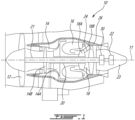
Fig. 1 is a schematic cross-sectional view of an aircraft engine depicted as a gas turbine engine; -
Fig. 2 is a schematic cross-sectional view of a portion of the gas turbine engine ofFig. 1 ; -
Fig. 3 is an enlarged view of a portion ofFig. 2 ; -
Fig. 4A is an enlarged view of a portion ofFig. 3 illustrating a retaining ring and a support flange in a first relative position when the gas turbine engine is powered off; -
Fig. 4B is an enlarged view of the portion ofFig. 3 illustrating the retaining ring and the support flange in a second relative position when the gas turbine engine is running; and -
Fig. 5 is a flowchart illustrating steps of mounting a component to a casing of the engine ofFig. 1 . -
Fig. 1 illustrates an aircraft engine depicted as agas turbine engine 10 of a type preferably provided for use in subsonic flight, generally comprising in serial flow communication afan 12 through which ambient air is propelled, acompressor section 14 for pressurizing the air, acombustor 16 in which the compressed air is mixed with fuel and ignited for generating an annular stream of hot combustion gases, and aturbine section 18 for extracting energy from the combustion gases. Thefan 12, thecompressor section 14, and theturbine section 18 are rotatable about acentral axis 11 of thegas turbine engine 10. - In the embodiment shown, the
gas turbine engine 10 comprises a high-pressure spool having a high-pressure shaft 20 drivingly engaging a high-pressure turbine 18A of theturbine section 18 to a high-pressure compressor 14A of thecompressor section 14, and a low-pressure spool having a low-pressure shaft 21 drivingly engaging a low-pressure turbine 18B of the turbine section to a low-pressure compressor 14B of thecompressor section 14 and drivingly engaged to thefan 12. It will be understood that the contents of the present disclosure may be applicable to any suitable engines, such as turboprops and turboshafts, and reciprocating engines, such as piston and rotary engines without departing from the scope of the present disclosure. - Another
component 22, such as an accessory, herein a generator, is drivingly engaged by the low-pressure shaft 21 via a connecting arrangement or connectingsystem 30, which will be described further below. Thecomponent 22 may be an accessory, such as a pump, an electrical motor, and so on. Thecomponent 22 may be located within atail cone 23 of thegas turbine engine 10. - Referring to
Figs. 2-3 , a portion of thegas turbine engine 10 proximate thetail cone 23 and illustrating the connectingsystem 30 is shown. Thegas turbine engine 10 includes aninner casing 24 defining aflange 24A. Theflange 24A may be located axially between avane 18C of theturbine section 18 and asupport strut 25 that extends radially outwardly from thetail cone 23 and that is connected at its outer end to an outer casing 26 (Fig. 1 ) of thegas turbine engine 10. The connectingsystem 30 includes asupport flange 31 that is mounted (e.g., fastened, welded, etc) to theflange 24A of theinner casing 24. In some embodiments, thesupport flange 31 may be monolithic with theinner casing 24. In the embodiment shown, thecomponent 22 has a connectingsection 22A. The connectingsection 22A is sized to be secured to thesupport flange 31. In the present embodiment, the connectingsection 22A defines a substantiallycylindrical face 22B and thesupport flange 31 defines a substantially cylindrical recess that is sized to receive the connectingsection 22A of thecomponent 22. A spigot fit may therefore be created between the connectingsection 22A and thesupport flange 31. Hence, to assemble thecomponent 22 to thesupport flange 31, the connectingsection 22A is inserted in an axial direction relative to thecentral axis 11 in the recess. Anannular web 33 extend substantially transversely from a distal end of thesupport flange 31 toward thecentral axis 11. The connectingsection 22A may be bolted or fastened in any suitable way to theannular web 33. Theannular web 33 and the connectingsection 22A may define registering apertures circumferentially distributed about thecentral axis 11 for receiving suitable fasteners. - Referring more particularly to
Fig. 3 , thesupport flange 31 may extend circumferentially all around thecentral axis 11. Thesupport flange 31 has aninner flange face 31A that faces thecentral axis 11 and anouter flange face 31B that faces away from thecentral axis 11. Thesupport flange 31 includes a first material, which may be INCONEL 718™. As shown inFig. 3 , the connectingsection 22A of thecomponent 22 is secured to thesupport flange 31. In the depicted embodiment, the connectingsection 22A is in abutment against theinner flange face 31A of thesupport flange 31. A tight fit engagement or compression fit may be provided between the connectingsection 22A of thecomponent 22 and thesupport flange 31. - In use, the temperature inside the
gas turbine engine 10 may be such that the different components increase in dimension with heat. In the present case, the coefficient of thermal expansion of thesupport flange 31 may be greater than that of the connecting section of thecomponent 22. Therefore, the engagement between thesupport flange 31 and thecomponent 22 may become loose when thegas turbine engine 10 is at operational temperatures because the diameter of thesupport flange 31 may increase more than a diameter of the connectingsection 22A of thecomponent 22. - Still referring to
Fig. 3 , in the present embodiment, a retainingring 32 is mounted to thesupport flange 31. More specifically, the retainingring 32 may be in abutment against theouter flange face 31B of thesupport flange 31. The retainingring 32 may extend circumferentially all around thecentral axis 11. According to at least one embodiment, the retainingring 32 is configured to have an interference fit with thesupport flange 31. In some embodiments, the retainingring 32 may include a plurality of ring sections circumferentially distributed around thecentral axis 11 and secured to one another. The retainingring 32 may include a second material that has a coefficient of thermal expansion that is less than that of the first material of thesupport flange 31. The second material may include, for instance, titanium. Therefore, in use when thesupport flange 31 increases in diameter because of thermal expansion it is restrained by the retainingring 32 that also increases because of thermal expansion, but less then thesupport flange 31 because of the differences in their coefficients of thermal expansion. Consequently, during an increase of temperature inside thegas turbine engine 10, thesupport flange 31 may remain securely connected to the connectingsection 22A of thecomponent 22 thanks to the retainingring 32 that maintains proper engagement between thesupport flange 31 andcomponent 22. Stated differently, thermal expansion of thesupport flange 31 may be impeded by the retainingring 32. - In some embodiments, it was observed that repeated cycles of heating and cooling cycles with starting and shutting down the
gas turbine engine 10 resulted in the retainingring 32 moving axially relative to thecentral axis 11 and relative to thesupport flange 31. In some cases, this resulted in the retaining ring slipping off thesupport flange 31. As will be explained below, the present connectingsystem 30 as features that may limit the situation from arising. - Still referring to
Fig. 3 , in the present embodiment, theouter flange face 31B defines aflange recess 31C and the retainingring 32 defines aring protrusion 32A that extends toward thecentral axis 11. Thering protrusion 32A is at least partially received within theflange recess 31C. The retainingring 32 may therefore be axially locked relative to thesupport flange 31 by the engagement of thering protrusion 32A inside theflange recess 31C. The retainingring 32 may also define aring recess 32B that partially receives aflange protrusion 31D defined by theouter flange face 31B of thesupport flange 31. An axial width of thering recess 32B of the retainingring 32 is greater than an axial width of theflange protrusion 31D of thesupport flange 31. - Referring now to
Fig. 4A , theflange recess 31C is bounded on a first axial side by a slopedrecess face 31E. The sloped recess face 31E extends radially outwardly and axially from abottom face 31F of theflange recess 31C. Thering protrusion 32A defines a slopedprotrusion face 32C that extends radially outwardly and axially from anend face 32D of thering protrusion 32A. The sloped protrusion face 32C is in abutment against the slopedrecess face 31E. - Referring to
Figs. 4A-4B , thesupport flange 31 is movable in a radial direction relative to thecentral axis 11 toward the retainingring 32 between a first position depicted inFig. 4A to a second position depicted inFig. 4B . The first position corresponds to a state in which thegas turbine engine 10 is powered off and at a temperature corresponding to that of an environment in which thegas turbine engine 10 is located and the second position corresponds to a state in which thegas turbine engine 10 is powered on and at steady-state operational temperatures. The temperature of the retainingring 32 andsupport flange 31 in the first position ofFig. 4A may be about 70 degrees Fahrenheit, whereas, in the second position ofFig. 4B , the temperature of the retainingring 32 andsupport flange 31 may be about 350 degrees Fahrenheit. A radial distance relative to thecentral axis 11 between theend face 32D of thering protrusion 32A and thebottom face 31F of theflange recess 31C is less in the second position ofFig. 4B then it is in the first position ofFig. 4A . In other words, thering protrusion 32A extends deeper inside theflange recess 31C in the second position than in the first position. - Because both of the sloped recess face 31E and the sloped
protrusion face 32C are substantially parallel to one another and angled relative to thecentral axis 11, radial movements between the retainingring 32 and asupport flange 31 translates into an axial movement along thecentral axis 11 between the retainingring 32 and asupport flange 31. More specifically, and in the embodiment shown, upon the retainingring 32 and thesupport flange 31 increasing in their respective diameters because of the thermal expansion along directions depicted by arrows A1 onFig. 4B , the retainingring 32 moves axially along a direction depicted by arrow A2 until it abuts ashoulder 31G defined by thesupport flange 31 on a second axial side of theflange recess 31C and that is facing the retainingring 32. Theshoulder 31G may extend substantially perpendicularly from theouter flange face 31B of thissupport flange 31. In operating temperatures, the retainingring 32 may be biased against theshoulder 31G by the engagement of the twosloped faces - Therefore, at each cooling and heating cycle, engagement of the two slope faces 32C, 31E pushes the retaining
ring 32 toward theshoulder 31G and realigns thering protrusion 32A with theflange recess 31C. Consequently, the retainingring 32 may remain properly engaged to thesupport flange 31 regardless of the number of cooling and heating cycles thegas turbine engine 10 is subjected to. In other words, the ramp between the parts may cause the retainingring 32 to be seated during every thermal cycle. The retainingring 32 may be installed by thermal differential between thesupport flange 31 and retainingring 32. The normalization of temperatures may produce an interlock as explain above. In the present embodiment, the retainingring 32 may remain engaged to thesupport flange 31 without any fasteners. In other words, engagement of the retainingring 32 to thesupport flange 31 may be free of fasteners. - Referring now to
Fig. 5 , a method of mounting thecomponent 22 to theinner casing 24 of thegas turbine engine 10 is shown at 500. Themethod 500 includes engaging the connectingsection 22A of thecomponent 22 to thesupport flange 31, which is secured to theinner casing 24, at 502. As previously explained, thesupport flange 31 includes a first material. Then, themethod 500 includes disposing the retainingring 32 around thesupport flange 31 and in abutment against thesupport flange 31 to sandwich thesupport flange 31 between the connectingsection 22A and the retainingring 32, at 504. As previously explained, the retainingring 32 includes a second material that has a coefficient of thermal expansion that is less than that of the first material. - In the embodiment shown, the disposing of the retaining
ring 32 around thesupport flange 31 includes inserting thering protrusion 32A of the retainingring 32 inside theflange recess 31C of thesupport flange 31. In the present embodiment, themethod 500 includes putting the twosloped faces support flange 31 in the radial direction relative to thecentral axis 11 induces an axial movement of the retainingring 32 relative to thesupport flange 31. - According to at least some embodiments would like but the
ring 32 is designed to have an interference fit with thesupport flange 31. At assembly, thesupport flange 31 will be cooled so thering 32 can be easily pressed on and locked into place when it reaches normal temperatures. The thickness of thering 32 will be balanced against the thickness of theflange 31 to produce an expansion rate at the spigot fit to match the mating component (e.g. the generator). - According to at least some embodiments, the geometry defined by the contact diameters between the support flange and the retaining ring, the relative thickness of the flange spigot and retaining ring, the relative expansion coefficient between the two materials of the support flange and the retaining ring, and the Young modulus of the two materials are all selected in combination relative to the characteristics of the operating envelope of the support flange such that thermal expansion of the support flange is impeded by the retaining ring.
- The embodiments described in this document provide non-limiting examples of possible implementations of the present technology. Upon review of the present disclosure, a person of ordinary skill in the art will recognize that changes may be made to the embodiments described herein without departing from the scope of the present technology. Yet further modifications could be implemented by a person of ordinary skill in the art in view of the present disclosure, which modifications would be within the scope of the present technology.
Claims (12)
- An aircraft engine (10), comprising:a casing (24) extending circumferentially around a central axis (11);a support flange (31) secured to the casing (24) and extending circumferentially around the central axis (11), the support flange (31) having an inner flange face (31A) facing the central axis (11) and an outer flange face (31B) facing away from the central axis (11), the support flange (31) including a first material;a component (22) drivingly engaged by a shaft (21) of the aircraft engine (10), the component (22) having a connecting section (22A) extending around the central axis (11), the connecting section (22A) having a connecting face (22B) facing away from the central axis (11), the inner flange face (31A) in abutment against the connecting face (22B); anda retaining ring (32) extending circumferentially around the central axis (11), the retaining ring (32) in abutment against the outer flange face (31B) of the support flange (31), the retaining ring (32) including a second material having a coefficient of thermal expansion being less than that of the first material of the support flange (31).
- The aircraft engine (10) of claim 1, wherein the outer flange face (31B) defines a recess (31C), the retaining ring (32) defining a protrusion (32A) extending toward the central axis (11), the protrusion (32A) at least partially received within the recess (31C).
- The aircraft engine (10) of claim 2, wherein the outer flange face (31B) is movable toward the retaining ring (32) between a first position when the aircraft engine (10) is powered off and a second position when the aircraft engine (10) is running, a radial distance relative to the central axis (11) between an end face (32D) of the protrusion (32A) and a bottom face (31F) of the recess (31C) being less in the second position than in the first position.
- The aircraft engine (10) of claim 3, wherein the recess (31C) is bounded on a first axial side by a sloped recess face (31E) extending radially outwardly and axially from the bottom face (31F) of the recess (31C), the protrusion (32A) defining a sloped protrusion face (32C) extending radially outwardly and axially from the end face of the protrusion (32A), the sloped protrusion face (32C) in abutment against the sloped recess face (31E) such that the retaining ring (32) moves axially relative to the support flange (31) between the first position and the second position.
- The aircraft engine (10) of claim 4, wherein the support flange (31) defines a shoulder (31G) extending radially outwardly from the outer flange face (31B), the shoulder (31G) facing the retaining ring (32), the retaining ring (32) biased against the shoulder (31G) in the second position by an interaction between the sloped protrusion face (32C) and the sloped recess face (31E).
- The aircraft engine (10) of any one of claims 1 to 5, wherein the connecting face (22B) and the inner flange face (31A) are biased against one another via a compression fit.
- The aircraft engine (10) of any one of claims 1 to 6, wherein the first material is INCONEL 718™.
- The aircraft engine (10) of any one of claims 1 to 7, wherein the second material is titanium.
- The aircraft engine (10) of any one of claims 1 to 8, wherein the component (22) is a generator.
- A method of mounting a component (22) to a casing (24) of a aircraft engine (10), comprising:engaging a connecting section (22A) of the component (22) to a support flange (31) secured to the casing (24), the support flange (31) including a first material; anddisposing a retaining ring (32) around the support flange (31) and in abutment against the support flange (31) to sandwich the support flange (31) between the connecting section (22A) and the retaining ring (32), the retaining ring (32) including a second material having coefficient of thermal expansion being less than that of the first material.
- The method of claim 10, wherein the disposing of the retaining ring (32) around the support flange (31) includes inserting a protrusion (32A) of the retaining ring (32) into a recess (31C) defined by the support flange (31).
- The method of claim 11, comprising abutting a first sloping face (31E) axially bounding the recess (31C) against a second sloping face (32C) defined by the protrusion (31D) such that thermal expansion of the support flange (31) induces an axial movement of the retaining ring (32) relative to the support flange (31).
Applications Claiming Priority (1)
| Application Number | Priority Date | Filing Date | Title |
|---|---|---|---|
| US17/452,917 US11732609B2 (en) | 2021-10-29 | 2021-10-29 | Connecting arrangement between components of an aircraft engine |
Publications (1)
| Publication Number | Publication Date |
|---|---|
| EP4174297A1 true EP4174297A1 (en) | 2023-05-03 |
Family
ID=84047538
Family Applications (1)
| Application Number | Title | Priority Date | Filing Date |
|---|---|---|---|
| EP22204812.6A Pending EP4174297A1 (en) | 2021-10-29 | 2022-10-31 | Connecting arrangement between components of an aircraft engine |
Country Status (3)
| Country | Link |
|---|---|
| US (1) | US11732609B2 (en) |
| EP (1) | EP4174297A1 (en) |
| CA (1) | CA3180308A1 (en) |
Families Citing this family (1)
| Publication number | Priority date | Publication date | Assignee | Title |
|---|---|---|---|---|
| US12529322B1 (en) | 2024-11-08 | 2026-01-20 | Pratt & Whitney Canada Corp. | Gas turbine engine stator vane stage |
Citations (3)
| Publication number | Priority date | Publication date | Assignee | Title |
|---|---|---|---|---|
| US20160123172A1 (en) * | 2013-06-11 | 2016-05-05 | General Electric Company | Passive control of gas turbine clearances using ceramic matrix composites inserts |
| US20170227152A1 (en) * | 2016-02-04 | 2017-08-10 | General Electric Company | Flange joint assembly for use in a gas turbine engine |
| EP4098858A1 (en) * | 2021-06-03 | 2022-12-07 | Pratt & Whitney Canada Corp. | Bi-material joint for engine |
Family Cites Families (10)
| Publication number | Priority date | Publication date | Assignee | Title |
|---|---|---|---|---|
| US4552386A (en) * | 1983-08-22 | 1985-11-12 | United Technologies Corporation | Joints between cylinders of different materials |
| GB9606546D0 (en) * | 1996-03-28 | 1996-06-05 | Rolls Royce Plc | Gas turbine engine system |
| US20060013681A1 (en) * | 2004-05-17 | 2006-01-19 | Cardarella L J Jr | Turbine case reinforcement in a gas turbine jet engine |
| US7686575B2 (en) | 2006-08-17 | 2010-03-30 | Siemens Energy, Inc. | Inner ring with independent thermal expansion for mounting gas turbine flow path components |
| KR101021658B1 (en) | 2008-08-12 | 2011-03-17 | (주)계양정밀 | Turbocharger with variable nozzle unit |
| US8997496B2 (en) * | 2011-06-29 | 2015-04-07 | United Technologies Corporation | Hybrid exhaust component |
| US9003811B2 (en) * | 2011-11-28 | 2015-04-14 | Pratt & Whitney Canada Corp. | Support for electric machine in a turbine engine |
| US9097134B2 (en) * | 2012-09-14 | 2015-08-04 | Pratt & Whitney Canada Corp. | Air cooling design for tail-cone generator installation |
| FR3100845B1 (en) * | 2019-09-13 | 2022-07-08 | Safran Nacelles | Outer nozzle member for turbomachine |
| US11459980B2 (en) * | 2019-12-02 | 2022-10-04 | Rohr, Inc. | Compression ring for exhaust nozzle and center body attachment |
-
2021
- 2021-10-29 US US17/452,917 patent/US11732609B2/en active Active
-
2022
- 2022-10-27 CA CA3180308A patent/CA3180308A1/en active Pending
- 2022-10-31 EP EP22204812.6A patent/EP4174297A1/en active Pending
Patent Citations (3)
| Publication number | Priority date | Publication date | Assignee | Title |
|---|---|---|---|---|
| US20160123172A1 (en) * | 2013-06-11 | 2016-05-05 | General Electric Company | Passive control of gas turbine clearances using ceramic matrix composites inserts |
| US20170227152A1 (en) * | 2016-02-04 | 2017-08-10 | General Electric Company | Flange joint assembly for use in a gas turbine engine |
| EP4098858A1 (en) * | 2021-06-03 | 2022-12-07 | Pratt & Whitney Canada Corp. | Bi-material joint for engine |
Also Published As
| Publication number | Publication date |
|---|---|
| US20230136870A1 (en) | 2023-05-04 |
| US11732609B2 (en) | 2023-08-22 |
| CA3180308A1 (en) | 2023-04-29 |
Similar Documents
| Publication | Publication Date | Title |
|---|---|---|
| EP3196517B1 (en) | Secondary seal device(s) with alignment tab(s) | |
| US8491267B2 (en) | Retaining ring arrangement for a rotary assembly | |
| EP2951399B1 (en) | Turbine shroud and corresponding assembly method | |
| EP2278125B1 (en) | Turbine nozzle assembly including radially-compliant spring member for gas turbine engine | |
| CA2638542C (en) | Radial loading element for turbine vane | |
| US20060045745A1 (en) | Vane attachment arrangement | |
| US9062565B2 (en) | Gas turbine engine containment device | |
| US10280782B2 (en) | Segmented clearance control ring | |
| US10161257B2 (en) | Turbine slotted arcuate leaf seal | |
| US10519811B2 (en) | Flange heat shield | |
| US20120031104A1 (en) | Turbine engine | |
| CA2638527A1 (en) | Axial loading element for turbine vane | |
| US20050058540A1 (en) | Turbine engine sealing device | |
| EP3453839B1 (en) | Gas turbine engine blade outer air seal | |
| CA2970382C (en) | Shroud housing supported by vane segments | |
| US11732609B2 (en) | Connecting arrangement between components of an aircraft engine | |
| CA2992684C (en) | Turbine housing assembly | |
| US20200200019A1 (en) | Turbomachine disc cover mounting arrangement | |
| US11802493B2 (en) | Outlet guide vane assembly in gas turbine engine | |
| GB2431225A (en) | Liner Component for a Combustor | |
| EP1378631A2 (en) | Methods and apparatus for turbine nozzle locks | |
| EP4194665B1 (en) | Sealing assembly and turbomachine including same | |
| US9097142B2 (en) | Alignment of static parts in a gas turbine engine | |
| US11959389B2 (en) | Turbine shroud segments with angular locating feature | |
| EP4008885B1 (en) | Gas turbine engine combustor |
Legal Events
| Date | Code | Title | Description |
|---|---|---|---|
| PUAI | Public reference made under article 153(3) epc to a published international application that has entered the european phase |
Free format text: ORIGINAL CODE: 0009012 |
|
| STAA | Information on the status of an ep patent application or granted ep patent |
Free format text: STATUS: THE APPLICATION HAS BEEN PUBLISHED |
|
| AK | Designated contracting states |
Kind code of ref document: A1 Designated state(s): AL AT BE BG CH CY CZ DE DK EE ES FI FR GB GR HR HU IE IS IT LI LT LU LV MC ME MK MT NL NO PL PT RO RS SE SI SK SM TR |
|
| STAA | Information on the status of an ep patent application or granted ep patent |
Free format text: STATUS: REQUEST FOR EXAMINATION WAS MADE |
|
| 17P | Request for examination filed |
Effective date: 20231101 |
|
| RBV | Designated contracting states (corrected) |
Designated state(s): AL AT BE BG CH CY CZ DE DK EE ES FI FR GB GR HR HU IE IS IT LI LT LU LV MC ME MK MT NL NO PL PT RO RS SE SI SK SM TR |
|
| STAA | Information on the status of an ep patent application or granted ep patent |
Free format text: STATUS: EXAMINATION IS IN PROGRESS |
|
| 17Q | First examination report despatched |
Effective date: 20250129 |