EP4174290A1 - Support plate for engine casing flange - Google Patents
Support plate for engine casing flange Download PDFInfo
- Publication number
- EP4174290A1 EP4174290A1 EP22204819.1A EP22204819A EP4174290A1 EP 4174290 A1 EP4174290 A1 EP 4174290A1 EP 22204819 A EP22204819 A EP 22204819A EP 4174290 A1 EP4174290 A1 EP 4174290A1
- Authority
- EP
- European Patent Office
- Prior art keywords
- support plate
- flange
- plane
- extending
- center axis
- Prior art date
- Legal status (The legal status is an assumption and is not a legal conclusion. Google has not performed a legal analysis and makes no representation as to the accuracy of the status listed.)
- Granted
Links
Images



Classifications
-
- F—MECHANICAL ENGINEERING; LIGHTING; HEATING; WEAPONS; BLASTING
- F01—MACHINES OR ENGINES IN GENERAL; ENGINE PLANTS IN GENERAL; STEAM ENGINES
- F01D—NON-POSITIVE DISPLACEMENT MACHINES OR ENGINES, e.g. STEAM TURBINES
- F01D25/00—Component parts, details, or accessories, not provided for in, or of interest apart from, other groups
- F01D25/24—Casings; Casing parts, e.g. diaphragms, casing fastenings
- F01D25/243—Flange connections; Bolting arrangements
-
- F—MECHANICAL ENGINEERING; LIGHTING; HEATING; WEAPONS; BLASTING
- F05—INDEXING SCHEMES RELATING TO ENGINES OR PUMPS IN VARIOUS SUBCLASSES OF CLASSES F01-F04
- F05D—INDEXING SCHEME FOR ASPECTS RELATING TO NON-POSITIVE-DISPLACEMENT MACHINES OR ENGINES, GAS-TURBINES OR JET-PROPULSION PLANTS
- F05D2240/00—Components
- F05D2240/90—Mounting on supporting structures or systems
- F05D2240/91—Mounting on supporting structures or systems on a stationary structure
-
- F—MECHANICAL ENGINEERING; LIGHTING; HEATING; WEAPONS; BLASTING
- F05—INDEXING SCHEMES RELATING TO ENGINES OR PUMPS IN VARIOUS SUBCLASSES OF CLASSES F01-F04
- F05D—INDEXING SCHEME FOR ASPECTS RELATING TO NON-POSITIVE-DISPLACEMENT MACHINES OR ENGINES, GAS-TURBINES OR JET-PROPULSION PLANTS
- F05D2260/00—Function
- F05D2260/30—Retaining components in desired mutual position
-
- F—MECHANICAL ENGINEERING; LIGHTING; HEATING; WEAPONS; BLASTING
- F05—INDEXING SCHEMES RELATING TO ENGINES OR PUMPS IN VARIOUS SUBCLASSES OF CLASSES F01-F04
- F05D—INDEXING SCHEME FOR ASPECTS RELATING TO NON-POSITIVE-DISPLACEMENT MACHINES OR ENGINES, GAS-TURBINES OR JET-PROPULSION PLANTS
- F05D2260/00—Function
- F05D2260/30—Retaining components in desired mutual position
- F05D2260/31—Retaining bolts or nuts
Definitions
- the application relates generally to gas turbine engines and, more particularly, to casings for gas turbine engines.
- One casing in a gas turbine engine may be connected to another casing of the gas turbine engine at a joint composed of mating flanges from each casing.
- the casings are secured to one another by bolting their flanges together.
- the casings experience loads during operation of the gas turbine engine. These loads may stress the bolts and/or the mating flanges, which may cause deformation of the flanges.
- an engine casing comprising: an annular casing wall defining a center axis, and a flange extending from the annular casing wall radially outwardly to an outer flange wall, the flange having a plurality of flange holes radially inward of the outer flange wall; a support plate against the flange, the support plate having an anti-rotation rib abutting the outer flange wall and a misalignment tab extending radially outwardly from the anti-rotation rib, the support plate having a support plate hole aligned with one flange hole of the plurality of flange holes; and a fastener extending through the support plate hole and through the one flange hole.
- the support plate extends between an outer end and an inner end, the misalignment tab disposed at the outer end and the inner end being chamfered.
- the annular casing wall and the flange meet at a joint having a fillet
- the misalignment tab of the support plate disposed at an outer end of the support plate and the support plate having an inner end with a chamfer, the chamfer and the fillet abutting each other and having complementary shapes.
- the support plate defines a first support plate plane parallel to the flange, the anti-rotation rib extending from the support plate toward the outer flange wall in a direction perpendicular to the first support plate plane.
- the anti-rotation rib has a radially-innermost surface mated with a radially-outermost surface of the outer flange wall.
- the support plate defines a first support plate plane parallel to the flange and extending through the support plate, the anti-rotation rib including a first anti-rotation rib extending from the support plate toward the outer flange wall in a direction perpendicular to the first support plate plane, the anti-rotation rib including a second anti-rotation rib extending from the support plate away from the outer flange wall in the direction perpendicular to the first support plate plane.
- first and second anti-rotation ribs are symmetric about the first support plate plane.
- the support plate defines a first support plate plane parallel to the flange and extending through the support plate, the misalignment tab of the support plate disposed at an outer end of the support plate and the support plate having an inner end with a first chamfer and a second chamfer, the first and second chamfers being symmetric about the first support plate plane.
- the support plate defines a first support plate plane perpendicular to a hole center axis of the support plate hole, and a second support plate plane extending radially through the hole center axis and perpendicular to the first support plate plane, the misalignment tab being symmetric about the second support plate plane.
- the misalignment tab includes at least one protruding portion and at least one recessed portion, the at least one protruding portion positioned radially outwardly of the at least one recessed portion.
- the support plate defines a second support plate plane extending radially through a hole center axis of the support plate hole and perpendicular to the flange, the at least one protruding portion being symmetric about the second support plate plane.
- a support plate for an engine casing comprising: a body having a first side and a second side opposite the first side, the body extending between an outer end and an inner end and defining a center axis; a support plate hole extending through the body between the first and second sides and about the center axis; an anti-rotation rib on one or both of the first and second sides and disposed radially outwardly of the support plate hole; and a misalignment tab extending radially outwardly from the anti-rotation rib at the outer end.
- the inner end is chamfered.
- the body defines a first support plate plane perpendicular to the center axis and extending through the body between the first and second sides, the anti-rotation rib extending away from the one or both of the first and second sides in a direction perpendicular to the first support plate plane.
- the body defines a first support plate plane perpendicular to the center axis and extending through the body between the first and second sides, the anti-rotation rib including a first anti-rotation rib extending away from the first side in a direction perpendicular to the first support plate plane, the anti-rotation rib including a second anti-rotation rib extending away from the second side and away from the first anti-rotation rib in the direction perpendicular to the first support plate plane.
- first and second anti-rotation ribs are symmetric about the first support plate plane.
- the body defines a first support plate plane perpendicular to the center axis and extending through the body between the first and second sides, the inner end having a first chamfer and a second chamfer, the first and second chamfers being symmetric about the first support plate plane.
- the body defines a first support plate plane perpendicular to the center axis and extending through the body between the first and second sides, and a second support plate plane extending radially through the center axis and perpendicular to the first support plate plane, the misalignment tab being symmetric about the second support plate plane.
- the misalignment tab includes at least one protruding portion and at least one recessed portion, the at least one protruding portion positioned radially outwardly of the at least one recessed portion.
- the body defines a second support plate plane extending radially through the center axis and perpendicular to the first and second sides, the at least one protruding portion being symmetric about the second support plate plane.
- a casing assembly of an engine comprising: a first casing having a first flange with first flange holes; a second casing having a second flange against the first flange, the second flange having second flange holes, at least one second flange hole of the second flange holes aligned with at least one first flange hole of the first flange holes; a support plate against one of the first flange and the second flange, the support plate having an anti-rotation rib abutting the one of the first flange and the second flange and a misalignment tab extending radially outwardly from the anti-rotation rib, the support plate having a support plate hole aligned with the at least one first flange hole and with the at least one second flange hole; and a fastener extending through the support plate hole, through the at least one first flange hole, and through the at least one second flange hole.
- a method of strengthening a flange of an engine casing comprising: abutting a support plate against a portion of the flange having a flange hole; aligning a support plate hole with the flange hole by abutting an outer end of the support plate against an outer wall of the flange, and by having part of the support plate protrude radially outwardly from the outer wall of the flange; and securing the support plate to the portion of the flange.
- Fig. 1 illustrates a gas turbine engine 10 of a type preferably provided for use in subsonic flight, generally comprising in serial flow communication a fan 12 through which ambient air is propelled, a compressor section 14 for pressurizing the air, a combustor 16 in which the compressed air is mixed with fuel and ignited for generating an annular stream of hot combustion gases, and a turbine section 18 for extracting energy from the combustion gases.
- Some of the components of the gas turbine engine 10 are rotatable about a longitudinal center axis 11.
- the gas turbine engine 10 includes a casing assembly 13.
- the casing assembly 13 is an annular body housing within its interior one or more components of the gas turbine engine 10, such as the fan 12.
- the casing assembly 13 is formed by attaching two components together - a first casing 15 and a second casing 17.
- One or both of the first and second casings 15,17 may be made up of interconnected casing sections or segments.
- the casing assembly 13 surrounds the fan 12 of the gas turbine engine 10, and may thus be referred to as a "fan casing" or a "fan casing assembly”.
- the casing assembly 13 in alternate embodiments may enclose or surround other components of the gas turbine engine 10.
- the specific size, shape, and configuration of the casing assembly 13, as described and/or illustrated herein, is exemplary only. Accordingly, the specific size, shape, and/or configuration of the casing assembly 13 generally, as well as portions thereof, may be selected to accommodate other components than the first and second casings 15,17.
- the first casing 15 includes and is defined by an annular first casing wall 15W
- the second casing 17 includes and is defined by an annular second casing wall 17W.
- the first casing 15 includes a first flange 15F
- the second casing 17 includes a second flange 17F.
- the first and second flanges 15F,17F extend substantially radially outwardly with respect to the center axis 11 from their respective casing walls 15W,17W.
- each of the first and second flanges 15F, 17F may be oriented at any angle relative to each respective casing wall 15W, 17W, or may extend from any other component, that enables the casing assembly 13 to function.
- first and second flanges 15F, 17F is a continuous body extending circumferentially relative to the center axis 11 around their respective casing walls 15W,17W.
- one or both of the first and second flanges 15F, 17F includes, or is made up of, discrete flange segments having a circumferential extent relative to the center axis 11.
- first and second casings 15,17 are secured together by being coupled along the interface of the first and second flanges 15F,17F.
- the first and second flanges 15F, 17F are abutted together to mate along surfaces of the flanges 15F, 17F, bolts 24 are inserted through aligned holes in the first and second flanges 15F,17F, and the bolts are subsequently tightened to secure the mating first and second flanges 15F, 17F together, as explained in greater detail below with reference to Figs. 2A and 2B .
- the first flange 15F includes a first flange hole 15FH and the second flange 17F includes a second flange hole 17FH.
- the first and second flange holes 15FH,17FH are configured to receive a flange bolt, or simply one of the bolts 24.
- the bolt 24 is inserted through each flange hole 15FH,17FH.
- Some or all of the first and second flange holes 15FH,17FH are aligned along a hole center axis 26 of the flange holes 15FH, 17FH.
- the bolt 24 is securely fastened with a nut 28.
- An optional washer or spacer may be inserted over the bolt 24 and paired with the nut 28.
- the first flange 15F defines a first flange mating surface 15FM and an oppositely disposed first flange opposite surface 15FO.
- the second flange 17F defines a second flange mating surface 17FM and an oppositely disposed second flange opposite surface 17FO.
- the first flange mating surface 15FM abuts against the second flange mating surface 17FM when the first and second flanges 15F,17F are coupled together.
- at least a portion of first and second flange mating surfaces 15FM, 17FM is substantially parallel to at least a portion of each respective opposite flange surface 15FO, 17FO.
- Each flange hole 15FH,17FH respectively, extends between each respective mating surface 15FM,17FM and each opposite surface 15FO, 17FO.
- the first flange 15F has a generally rectangular cross-sectional profile and is formed such that the first flange mating surface 15FM extends from an outer flange wall 15FW of the first flange 15F to the first casing wall 15W.
- the outer flange wall 15FW in Figs. 2A and 2B is the radially-outermost portion of the first flange 15F relative to the center axes 11,26.
- the outer flange wall 15FW in Figs. 2A and 2B defines the radially-outermost surface of the first flange 15F relative the center axes 11,26.
- the first flange mating surface 15FM is substantially parallel to the first flange opposite surface 15FO, and the center axis 26 of the first flange hole 15FH is oriented substantially perpendicularly to the surfaces 15FM, 15FO.
- the first flange hole 15FH is positioned radially inwardly of the outer flange wall 15FW, with respect to the hole center axis 26.
- the second flange mating surface 17FM extends from a radially-outer wall of the second flange 17F to the second casing wall 17W, and is substantially perpendicular to the second casing wall 17W.
- the joint 15J has, or is composed of, a fillet 15R.
- the fillet 15R is a rounding of the corner of the joint 15J and is defined by a radius and curvature.
- the fillet 15R forms the transition between the first casing wall 15W and the first flange 15F.
- the fillet 15R is along, and forms part of, the first flange opposite surface 15FO and is positioned opposite to the first flange mating surface 15FM.
- loads are generated and may act on the casing assembly 13.
- a high event load such as fan blade off, in which a fan blade separates from the fan 12 and impacts the casing assembly 13
- high event loads in addition to more routine loads imparting stresses over multiple operating cycles of the gas turbine engine 10, may place the flanges 15F, 17F under tensile loads and cause one or both of them to "peel" apart (i.e. to separate from each other), or may cause their flange holes 15FH, 17FH to distort in shape.
- the casing assembly 13 is provided with one or more support plates 30.
- the support plates 30 may be added to an existing flange 15F,17F that requires additional structural support or reinforcement against loads which may cause distortion of the flange holes 15FH,17FH or separation of the flanges 15F,17F under high event loads.
- the support plates 30 allow for strengthening a flange 15F,17F of the gas turbine engine 10 around the flange hole 15FH,17FH without having to remove the casing 15,17 containing the flange 15F, 17F for repair or replacement.
- the support plates 30 may allow for running the gas turbine engine 10 at loads higher than those for which the flange 15F, 17F was designed, and thereby possibly allow for continued use of the flange 15F, 17F without having to re-engineer it or the casing 15,17.
- the support plate 30 has a body 32.
- the body 32 is a planar rectangular prism which has a thickness defined between a first side 32M and a second side 32O that is opposite to the first side 32M.
- the body 32 also has a height defined between an outer end 32U and an inner end 32I.
- the body 32 has a support plate hole 32H that extends through the body between the first and second sides 32M, 32O.
- the support plate hole 32H is centered about a plate center axis 32A of the body 32.
- the first and second sides 32M, 32O are spaced apart from each other in an axial direction relative to the plate center axis 32A.
- the outer and inner ends 32O, 32I are spaced apart from each other in a radial direction relative to the plate center axis 32A, to define the height of the body 32.
- the support plate 30 is a "single-hole" support plate 30 because it has only one support plate hole 32H.
- the single-hole support plate 30 increases the versatility of the support plate 30, because it allows the support plate 30 to be used to reinforce any single flange hole 15FH,17FH, which may be desirable for flanges 15F,17F that do not have repeating hole patterns.
- the versatility provided by the single-hole support plate 30 may also allow it to be used to reinforce the flange 15F,17F at "empty" flange holes 15FH, 17FH that are not already occupied by harness brackets or the like.
- other configurations of the support plate 30 are possible and within the scope of the present disclosure.
- the support plate 30 has multiple support plate holes 32H and is used to reinforce a flange 15F,17F which has a repeating hole pattern.
- This configuration of the support plate 30 may include an annular or ring body 32, or a circumferentially-elongated body 32, each of which has multiple support plate holes 32H which are circumferentially spaced apart.
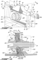
- Figs. 2A and 2B show the support plate 30 mounted and secured against the first flange 15F of the first casing 15.
- the first side 32M of the body 32 abuts against, and mates with, the first flange opposite surface 15FO and is parallel with the first flange mating surface 15FM.
- the outer end 32U is the radially-outer end of the body 32 relative to the hole center axes 26, and the inner end 321 is the radially-inner end of the body 32 and is positioned closer to the first casing wall 15W than the outer end 32U.
- the support plate hole 32H When mounted to the first flange 15F, the support plate hole 32H is aligned with the first and second flange holes 15FH, 17FH such that the plate center axis 32A is collinear with the hole center axes 26 of the first and second flange holes 15FH,17FH.
- the bolt 24 is inserted through the support plate hole 32H, through the first flange hole 15FH, and through the second flange hole 17FH.
- the support plate 30 is secured to the first flange 15F by being fastened to the first flange 15F with the bolt 24, and by tightening the bolt 24.
- a bolt head 24H abuts against the second side 32O of the body 32.
- Figs. 2A and 2B show one support plate 30 secured to the first and second flanges 15F,17F around one pair of their flange holes 15H,17H
- the casing assembly 13 may have multiple support plates 30 each secured to a corresponding pair of first and second flange holes 15FH, 17FH.
- Fig. 5 is an example of casing assembly 13 in which the flanges 15F, 17F do not have repeating hole patterns.
- Figs. 5 is an example of casing assembly 13 in which the flanges 15F, 17F do not have repeating hole patterns.
- the support plate 30 may have multiple support plate holes 32H, each of which is aligned with one pair of aligned flange holes 15FH,17FH of the flanges 15F,17F.
- the first flange 15F is thinner than the second flange 17F (when measured along an axial direction relative to the aligned center axes 26), such that only one support plate 30 may be needed to reinforce the casing assembly 13 at the first flange 15F, the second flange 17F being potentially thick enough to adequately resist bending or peeling.
- the casing assembly 13 in another embodiment has a second support plate 30 secured to the second flange 17F, either in addition to the first support plate 30 secured to the first flange 15F or not. Therefore, the description herein related to the support plate 30 and its features secured to the first flange 15F applies mutatis mutandis to a second support plate 30 secured to the second flange 17F.
- the support plate 30 has one or more features which help to orient it correctly with respect to the first flange 15F, and which prevent it from being installed incorrectly on the first flange 15F. Some of these features are now described in greater detail.
- the anti-rotation rib 40 helps to prevent the support plate 30 from rotating about the plate center axis 32A when it is being applied against the first flange 15F and secured in place by torqueing the bolt 24.
- the anti-rotation rib 40 (sometimes referred to herein simply as the "rib 40") thus helps the support plate 30 to have the correct orientation when the support plate 30 is being secured to the first flange 15F.
- the rib 40 also helps to prevent the support plate 30 from being installed incorrectly on the flange 15F by helping to ensure that the support plate 30 has the correct orientation.
- the rib 30 thus contributes to making the support plate 30 "mistake-proof", or less prone to being installed incorrectly.
- the rib 40 may have any suitable shape or form to achieve such functionality.
- the rib 40 includes a body 41 that has a height measured radially relative to the plate center axis 32A.
- the body 41 has a rib wall 42 that lies in a single straight plane (or possible a singly slightly curved plane).
- the rib 40 has a circumferential extent relative to the hole center axes 26 when the support plate 30 is installed on the first flange 15F, and is present on opposite circumferential sides of the hole center axes 26.
- the rib 40 is positioned between the outer and inner ends 32U, 32I of the body 32 of the support plate 30.
- the rib 40 is located on the first side 32M of the body 32, and extends transversely to the first side 32M toward the first flange 15F.
- the rib 40 abuts against the outer flange wall 15FW of the first flange 15F when the support plate 30 is positioned against the first flange 15F.
- the rib wall 42 defines or forms a radially-innermost surface of the rib 40, relative to the hole center axes 26. This radially-innermost surface abuts against, and mates with, part of the outer flange wall 15FW overlying the first flange hole 15FH.
- the outer flange wall 15FW forms an exposed, radially-outermost surface of the first flange 15F relative to the hole center axes 26.
- the rib 40 is thus positioned radially outwardly of the outer flange wall 15FW, relative to the hole center axes 26, when the support plate 30 is placed against the first flange 15F.
- the abutment of the rib wall 42 against the outer flange wall 15FW stops the support plate 30 from rotating about the plate center axis 32A when the bolt 24 is torqued.
- the anti-rotation functionality provided by the rib 40 may be beneficial to the single-hole support plate 30 of Figs. 2A and 2B , which may have a greater tendency to rotate about the plate center axis 32A when the bolt 24 is torqued.
- FIG. 2A and 2B shows the rib 40 extending over and overlaying most of the outer flange wall 15FW in an axial direction relative to the hole center axes 26.
- the rib 40 is axially longer than shown in Figs. 2A and 2B such that it extends axially over and overlays both the outer flange wall 15FW of the first flange 15F and some or all of the outer flange wall 17FW of the second flange 17F, such that the rib 40 abuts both flanges 15F, 17F.
- Figs. 2A and 2B show another feature of the support plate 30, a misalignment tab 50, which helps to orient the support plate 30 correctly with respect to the first flange 15F, and which prevents it from being installed incorrectly on the first flange 15F.
- the misalignment tab 50 helps to prevent the plate center axis 32A from aligning with the hole center axis 26 of the first flange 15F when the support plate 30 is incorrectly oriented with respect to the first flange 15F, as explained in greater detail below.
- the misalignment tab 50 helps to prevent the support plate 30 from being installed incorrectly on the first flange 15F because the bolt 24 cannot be inserted through the misaligned support plate and first flange holes 32H,15FH.
- the misalignment tab 50 (sometimes referred to herein simply as the "tab 50") thus helps the support plate 30 to have the correct orientation when the support plate 30 is being secured to the first flange 15F.
- the tab 50 also helps to prevent the support plate 30 from being installed incorrectly on the flange 15F, thereby helping to make the support plate 30 "mistake-proof", or less prone to being installed incorrectly.
- the tab 50 may have any suitable shape or form to achieve such functionality.
- the tab 50 extends radially outwardly from the rib 40, relative to the plate center axis 32A.
- the tab 50 is positioned radially outwardly of the support plate hole 32H, relative to the plate center axis 32A.
- the tab 50 thus forms a radially-outward extension of the support plate 30, such that part of the support plate 30 (i.e. the tab 50) protrudes radially outwardly from the outer flange wall 15W when the support plate 30 is secured to the first flange 15F.
- the height of the tab 50 contributes to misaligning the holes 32H,15FH when the support plate 30 is incorrectly oriented with respect to the first flange 15F.
- the tab 50 has a circumferential extent relative to the hole center axes 26 when the support plate 30 is installed on the first flange 15F, and is present directly radially outwardly of the holes 32H,15FH and radially aligned therewith when the support plate 30 is secured to the first flange 15F.
- the tab 50 is centered on the support plate 30.
- the tab 50 is positioned at the outer end 32U of the body 32 of the support plate 30, and defines the radially-outermost surface of the support plate 30, relative to the hole center axes 26, when the support plate 30 is secured to the first flange 15F.
- the tab 50 includes one or more protruding portions 52 and one or more recessed portions 54.
- the protruding portion 52 is positioned radially outwardly of the recessed portions 54 relative to the plate center axis 32A.
- the protruding portion 52 is thus a bump forming the outer end 32U of the support plate 30 which helps to prevent the holes 32H,15FH from aligning when the support plate 30 is incorrectly oriented with respect to the first flange 15F, as explained in greater detail below.
- the tab 50 defines a outer tab wall 56 which defines the radially-outermost surface of the support plate 30, relative to the aligned axes 32A,26 when the support plate 30 is secured to the first flange 15F.
- the outer tab wall 56 along the recessed portions 54 is positioned radially closer to the plate center axis 32A than the outer tab wall 56 along the protruding portion 52.
- the outer tab wall 56 along the protruding portion 52 lies in a single straight plane that is perpendicular to a line being radial to the plate center axis 32A.
- the outer tab wall 56 along the recessed portions 54 lies in a curved plane that slopes toward the plate center axis 32A from the outer tab wall 56 along the protruding portion 52.
- the protruding portion 52 has a height measured along a radial line from the plate center axis 32A that is greater than a distance between the first casing wall 15W and the radially-innermost surface of the first flange hole 15.
- the protruding portion 52 has a height measured along a radial line from the plate center axis 32A that is less than half the distance between the first casing wall 15W and the radially-innermost surface of the first flange hole 15.
- the height of the tab 50 may be any value which causes misalignment of the holes 32H, 15FH when the support plate 30 is incorrectly oriented with respect to the first flange 15F. Determining the height of the tab 50 may involve identifying the scenarios where the bolt 24 may still be inserted through the misaligned holes 32H,15FH, and selecting the height to avoid these scenarios.
- the tab 50 in another possible configuration has only a single protruding portion 52 and no recessed portions 54.
- the tab 150 in another possible configuration of the support plate 130 and referring to Fig. 6 has two protruding portions 152 on opposite circumferential ends of the body 132, where the protruding portions 152 are spaced apart by a single recessed portion 154.
- the tab 150 is on either end of the support plate 130, such that the recessed portion 154 provides a clearance which allows for a bracket 160 to be attached to the support plate 130.
- the bracket 160 may be used to attach objects such as a wiring harness to the support plate 130, and thus to the first flange 15F.
- the ability of the misalignment tab 50 to orient the support plate 30 correctly with respect to the first flange 15F, and to prevent the support plate 30 from being installed incorrectly on the first flange 15F, may be better appreciated with reference to Figs. 3 to 4B .
- the support plate 30 is shown in Figs. 3 to 4B in an incorrect orientation with respect to the first flange 15F, in which the tab 50 is positioned "upside down" (i.e. abutting the first casing wall 15W).
- Fig. 3 and 4B show that the protruding portion 52 of the tab 50 prevents the plate center axis 32A from aligning with the hole center axis 26.
- the tab 50 stops the support plate and first flange holes 32H,15FH from being aligned when the support plate 30 is positioned incorrectly with respect to the first flange 15F, such that the bolt 24 is prevented from being inserted into the holes 32H, 15FH and thus the support plate 30 cannot be secured to the first flange 15F.
- the installer will only be able to secure the support plate 30 to the first flange 15F by flipping the support plate 30 so that the misalignment tab 50 is radially outward.
- the misalignment tab 50 contributes to making the support plate 30 "mistake proof", because it allows the support plate 30 to be secured to the first flange 15F only when the support plate 30 has the correct orientation.
- FIGs. 4A and 4B Another misalignment or mistake-proof feature of the tab 50 is also shown in Figs. 4A and 4B .
- the edges of the protrusion portion 52 of the tap 50 are straight and free of bevels or chamfers. These straight edges prevent the first side 32M of the support plate 30 from being placed flush against the first flange mating surface 15FM of the first flange 15F, because the straight edges of the protrusion portion 52 do not conform to the shape of the fillet 15R at the joint 15J between the first casing wall 15W and the first flange 15F.
- the support plate 30 and its mistake-proof features disclosed herein help reduce the possibility, and may even completely prevent, the incorrect installation of the support plate 30 against the first flange 15F.
- This allows for a substantially or completely "mistake-proof" assembly of the support plate 30 with the first flange 15F, such that the installer may perform such installation "blind" (i.e. without actually seeing the first flange 15F).
- Such a blind installation may be performed in an aircraft engine 10 which is still mounted to a wing of the aircraft, and in which it is difficult to see or access the first flange 15F.
- the inability to see the support plate 30 during its attachment to the first flange 15F, which might otherwise have prevented the installation of the support plate 30 or required dismounting the engine 10, may no longer be an impediment to the installer from completing the work, because the mistake-proof features of the support plate 30 may allow the installer to still correctly attach the support plate 30 to the first flange 15F and thereby reinforce the first flange 15F.
- the support plate 30 when properly installed against the first flange 15F, the support plate 30 helps to structurally reinforce or strengthen the first flange 15F.
- the inner end 32I of the body 32 of the support plate 30 is chamfered, or has a chamfer 34.
- One or both sides 32M, 32O of the body 32 at the inner end 32I has a transitional wall 34T of the chamfer 34.
- the transitional wall 34T extends between a side wall 32W of the body 32 on the first or second sides 32M, 32O and a bottom wall 32B of the body 32 defining the radially-innermost surface of the body 32 relative to the aligned axes 32A,26.
- the transitional wall 34T may be a bevel, radius or any other surface that is shaped to be complementary to a shape of the fillet 15R, so that the chamfer 34 can be abutted against, and mate with, the fillet 15R at the joint 15J between the first casing wall 15W and the first flange 15F.
- the transitional wall 34T is curved over its length, such that chamfer 34 is defined by a radius of curvature that matches or is similar to a radius of curvature of the fillet 15R.
- the curvature of the chamfer 34 is complementary to the curvature of the fillet 15R (e.g. the chamfer 34 has a convex curvature matching the concave curvature of the fillet 15R), so that they can be mated together.
- the complementary shapes between the chamfer 34 and the fillet 15R may allow for tension loads acting on the casing walls 15W, 17W to be transferred to the support plate 30 at the chamfer 34.
- the chamfer 34 allows the inner end 32I of the support plate 30 to bear a portion of the load along the fillet 15R and parts of the casing wall 15W proximate the fillet 15R.
- the chamfer 34 may thus provide additional load bearing capacity to the support plate 30.
- the chamfer 34 of the support plate 30 helps to reinforce the fillet 15R during flange loading, and may reduce the tension loads causing the flanges 15F, 17F to "peel" apart (i.e. to separate from each other). By abutting against the joint 15J at the fillet 15R, the chamfer 34 may help to lower bending at the flange 15F,17F.
- the complementary shapes between the chamfer 34 and the fillet 15R may allow for clearances or gaps between the support plate 30 and the fillet 15R to be minimized or eliminated, helping to ensure that the support plate 30 can be installed flush with the first flange 15F and thus will not interfere with the fillet 15R which might impact the bolt clamp stack.
- the body 32 of the support plate 30 is symmetrical. As explained in greater detail below, the symmetry of the support plate 30 contributes to its mistake-proof attributes.
- the support plate 30 defines a first support plate plane P1.
- the first support plate plane P1 is parallel to the first flange 15F when the support plate 30 is secured to the first flange 15F.
- the first support plate plane P1 is parallel to the first flange mating and opposite surfaces 15FM, 15FO of the first flange 15F when the support plate 30 is secured to the first flange 15F.
- the first support plate plane P1 (sometimes referred to herein simply as "the first plane P1") extends through the body 32 of the support plate 30.
- the first plane P1 extends through the body 32 of the support plate 30 between the first side 32M and the second side 32O.
- the first plane P1 extends through the body 32 of the support plate 30 between the first side 32M and the second side 32O, and is spaced equidistantly from the first and second dies 32M, 32O.
- the first plane P1 is parallel to the first side 32M and the second side 32O.
- the first plane P1 is perpendicular to the plate center axis 32A.
- the first plane P1 is perpendicular to the aligned center axes 32A,26 when the support plate 30 is secured to the first flange 15F.
- the support plate 30 defines a second support plate plane P2.
- the second support plate plane P2 is perpendicular to the first flange 15F when the support plate 30 is secured to the first flange 15F.
- the second support plate plane P2 is perpendicular to the first flange mating and opposite surfaces 15FM, 15FO of the first flange 15F when the support plate 30 is secured to the first flange 15F.
- the second support plate plane P2 (sometimes referred to herein simply as "the second plane P2") extends through the body 32 of the support plate 30.
- the second plane P2 contains the plate center axis 32A of the body 32, extends radially from the plate center axis 32A, and has an upright or vertical orientation when the support plate 30 is secured to the first flange 15F.
- the second plane P2 is perpendicular to the first plane P1.
- the second plane P2 is perpendicular to the first and second sides 32M, 32O of the body 32.
- the second plane P2 may be considered to be a center plane because it contains the plate center axis 32A.
- the rib 40 includes a first rib 40A and a second rib 40B.
- the first and second ribs 40A,40B extend from the body 32 in a direction that is perpendicular to the first plane P1.
- the first rib 40A extends from the first side 32M of the body 32 in a direction that is perpendicular to the first plane P1 and also extends toward the outer flange wall 15FW. The first rib 40A is thus able to jut out over, and abut against, the outer flange wall 15FW.
- the second rib 40B extends from the second side 32O of the body 32 in a direction that is perpendicular to the first plane P1 and also extends away from the outer flange wall 15FW.
- the first and second anti-rotation ribs 40A,40B are symmetric about the first plane P1.
- the first and second ribs 40A,40B have reflectional symmetry (i.e. line or mirror symmetry), in that the first support plate plane P1 bisects the body 32 of the support plate 30, dividing it into two pieces in which the ribs 40A,40B are mirror images of each other.
- the symmetry of the ribs 40A,40B about the first plane P1 and their presence on both sides 32M, 32O of the support plate 30 helps to ensure that the support plate 30 will be correctly positioned against the first flange 15F, because the installer can abut either side 32M, 32O of the support plate 30 against the first flange 15F. This contributes to the mistake-proof attributes of the support plate 30, and further assists with a blind installation of the support plate 30.
- the misalignment tab 50 is symmetric about the second plane P2.
- the protruding and recessed portions 52,54 of the tab 50 are symmetric about the second plane P2.
- the tab 50 has reflectional symmetry (i.e. line or mirror symmetry), in that the second support plate plane P2 bisects the body 32 of the support plate 30, dividing it into two pieces in which the protruding and recessed portions 52,54 are mirror images of each other.
- the symmetry of the tab 50 about the second plane P2 helps to ensure that the support plate 30 will be correctly positioned against the first flange 15F, because the installer can abut either side 32M, 32O of the support plate 30 against the first flange 15F. This contributes to the mistake-proof attributes of the support plate 30, and further assists with a blind installation of the support plate 30.
- the chamfer 34 includes a first chamfer 34A and a second chamfer 34B.
- the first and second chamfers 34A,34B are at the inner end 32I.
- the first and second chamfers 34A,34B are shaped such that their transitional walls 34T slow toward the first plane P1 from the side walls 32W of the body, and also slope toward each other.
- the first chamfer 34A is present on the first side 32M of the body 32
- the second chamfer 34B is present on the second side 32O of the body 32.
- the first and second chamfers 34A,34B are symmetric about the first plane P1.
- the first and second chamfers 34A,34B have reflectional symmetry (i.e. line or mirror symmetry), in that the first support plate plane P1 bisects the body 32 of the support plate 30, dividing it into two pieces in which the chamfers 34A,34B are mirror images of each other.
- the symmetry of the chamfers 34A,34B about the first plane P1 and their presence on both sides 32M, 32O of the support plate 30 helps to ensure that the support plate 30 will be correctly positioned against the first flange 15F, because the installer can abut either side 32M, 32O of the support plate 30 against the first flange 15F. This contributes to the mistake-proof attributes of the support plate 30, and further assists with a blind installation of the support plate 30.
- the support plate 30 thus has features that are symmetrical in perpendicular planes P1,P2 of the support plate 30. This symmetry contributes to making the support plate 30 mistake proof, because it allows for either side 32M, 32O of the support plate 30 to be installed against the first flange 15F. This symmetry of the support plate 30, in combination with the anti-rotation rib 40 and the misalignment tab 50, helps to prevent installation of the bolt 24 until the support plate 30 is positioned in the correct configuration to reinforce the structural integrity of the first flange 15F.
- the first and second ribs 140A, 140B extend perpendicularly outwardly from their respective sides 132M, 132O of the body 132 of the support plate 130.
- the two protruding portions 152 of the tab 150 are spaced inwardly toward the middle of the body 132 from the first and second ribs 140A, 140B.
- the features of the support plate 130 shown in Fig. 6 have the same symmetry about the first and second planes P1,P2 described above.
- the description provided above of the features of the support plate 30 and their attributes applies mutatis mutandis to the features of the support plate 130 in Fig. 6 .
- the support plate 30,130 may be attached to the first flange 15F as follows. The installer first abuts either side 32M, 32O of the body 32 against the first flange mating surface 15FM.
- the installer may move the body 32 until 1) one of the ribs 40A,40B is abutting against the outer flange wall 15FW, 2) the protruding portion 52 of the misalignment tab 50 extends radially outwardly of the outer flange wall 15FW, and 3) one of the chamfers 34A,34B is flush against the fillet 15R of the joint 15J between the first casing wall 15W and the first flange 15F.
- the holes 32H,15FH will only be aligned if all three of these events occur, such that the support plate 30,130 can only be secured to the first flange 15F with the bolt 24 in the correct position when all three of these events have occurred.
- the method includes abutting the support plate 30,130 against a portion of the flange 15F.
- the method includes aligning the support plate hole 32H with the flange hole 15FH by abutting an outer end of the support plate 30,130 against the outer flange wall 15FW, and by having part of the support plate 30,130 protrude radially outwardly from the outer flange wall 15W.
- the method includes securing the support plate 30,130 to the portion of the flange 15F.
- a method of retrofitting a flange 15F of an engine casing 15 with the support plate 30,130 based on the disclosure herein.
- a method of repairing a flange 15F of an engine casing 15 with the support plate 30,130 based on the disclosure herein. These methods may include inspecting the flange 15F for damage, and validating the installation of the support plate 30,130, such as with a stress engineer.
Landscapes
- Engineering & Computer Science (AREA)
- Mechanical Engineering (AREA)
- General Engineering & Computer Science (AREA)
- Connection Of Plates (AREA)
Abstract
Description
- The application relates generally to gas turbine engines and, more particularly, to casings for gas turbine engines.
- One casing in a gas turbine engine may be connected to another casing of the gas turbine engine at a joint composed of mating flanges from each casing. The casings are secured to one another by bolting their flanges together. The casings experience loads during operation of the gas turbine engine. These loads may stress the bolts and/or the mating flanges, which may cause deformation of the flanges.
- There is disclosed an engine casing, comprising: an annular casing wall defining a center axis, and a flange extending from the annular casing wall radially outwardly to an outer flange wall, the flange having a plurality of flange holes radially inward of the outer flange wall; a support plate against the flange, the support plate having an anti-rotation rib abutting the outer flange wall and a misalignment tab extending radially outwardly from the anti-rotation rib, the support plate having a support plate hole aligned with one flange hole of the plurality of flange holes; and a fastener extending through the support plate hole and through the one flange hole.
- In a further embodiment of the above, the support plate extends between an outer end and an inner end, the misalignment tab disposed at the outer end and the inner end being chamfered.
- In a further embodiment of the above, the annular casing wall and the flange meet at a joint having a fillet, the misalignment tab of the support plate disposed at an outer end of the support plate and the support plate having an inner end with a chamfer, the chamfer and the fillet abutting each other and having complementary shapes.
- In a further embodiment of the above, the support plate defines a first support plate plane parallel to the flange, the anti-rotation rib extending from the support plate toward the outer flange wall in a direction perpendicular to the first support plate plane.
- In a further embodiment of the above, the anti-rotation rib has a radially-innermost surface mated with a radially-outermost surface of the outer flange wall.
- In a further embodiment of the above, the support plate defines a first support plate plane parallel to the flange and extending through the support plate, the anti-rotation rib including a first anti-rotation rib extending from the support plate toward the outer flange wall in a direction perpendicular to the first support plate plane, the anti-rotation rib including a second anti-rotation rib extending from the support plate away from the outer flange wall in the direction perpendicular to the first support plate plane.
- In a further embodiment of the above, the first and second anti-rotation ribs are symmetric about the first support plate plane.
- In a further embodiment of the above, the support plate defines a first support plate plane parallel to the flange and extending through the support plate, the misalignment tab of the support plate disposed at an outer end of the support plate and the support plate having an inner end with a first chamfer and a second chamfer, the first and second chamfers being symmetric about the first support plate plane.
- In a further embodiment of the above, the support plate defines a first support plate plane perpendicular to a hole center axis of the support plate hole, and a second support plate plane extending radially through the hole center axis and perpendicular to the first support plate plane, the misalignment tab being symmetric about the second support plate plane.
- In a further embodiment of the above, the misalignment tab includes at least one protruding portion and at least one recessed portion, the at least one protruding portion positioned radially outwardly of the at least one recessed portion.
- In a further embodiment of the above, the support plate defines a second support plate plane extending radially through a hole center axis of the support plate hole and perpendicular to the flange, the at least one protruding portion being symmetric about the second support plate plane.
- There is disclosed a support plate for an engine casing, the support plate comprising: a body having a first side and a second side opposite the first side, the body extending between an outer end and an inner end and defining a center axis; a support plate hole extending through the body between the first and second sides and about the center axis; an anti-rotation rib on one or both of the first and second sides and disposed radially outwardly of the support plate hole; and a misalignment tab extending radially outwardly from the anti-rotation rib at the outer end.
- In a further embodiment of the above, the inner end is chamfered.
- In a further embodiment of any of the above, the body defines a first support plate plane perpendicular to the center axis and extending through the body between the first and second sides, the anti-rotation rib extending away from the one or both of the first and second sides in a direction perpendicular to the first support plate plane.
- In a further embodiment of any of the above, the body defines a first support plate plane perpendicular to the center axis and extending through the body between the first and second sides, the anti-rotation rib including a first anti-rotation rib extending away from the first side in a direction perpendicular to the first support plate plane, the anti-rotation rib including a second anti-rotation rib extending away from the second side and away from the first anti-rotation rib in the direction perpendicular to the first support plate plane.
- In a further embodiment of any of the above, the first and second anti-rotation ribs are symmetric about the first support plate plane.
- In a further embodiment of any of the above, the body defines a first support plate plane perpendicular to the center axis and extending through the body between the first and second sides, the inner end having a first chamfer and a second chamfer, the first and second chamfers being symmetric about the first support plate plane.
- In a further embodiment of any of the above, the body defines a first support plate plane perpendicular to the center axis and extending through the body between the first and second sides, and a second support plate plane extending radially through the center axis and perpendicular to the first support plate plane, the misalignment tab being symmetric about the second support plate plane.
- In a further embodiment of any of the above, the misalignment tab includes at least one protruding portion and at least one recessed portion, the at least one protruding portion positioned radially outwardly of the at least one recessed portion.
- In a further embodiment of any of the above, the body defines a second support plate plane extending radially through the center axis and perpendicular to the first and second sides, the at least one protruding portion being symmetric about the second support plate plane.
- There is disclosed a casing assembly of an engine, the casing assembly comprising: a first casing having a first flange with first flange holes; a second casing having a second flange against the first flange, the second flange having second flange holes, at least one second flange hole of the second flange holes aligned with at least one first flange hole of the first flange holes; a support plate against one of the first flange and the second flange, the support plate having an anti-rotation rib abutting the one of the first flange and the second flange and a misalignment tab extending radially outwardly from the anti-rotation rib, the support plate having a support plate hole aligned with the at least one first flange hole and with the at least one second flange hole; and a fastener extending through the support plate hole, through the at least one first flange hole, and through the at least one second flange hole.
- There is disclosed a method of strengthening a flange of an engine casing, the method comprising: abutting a support plate against a portion of the flange having a flange hole; aligning a support plate hole with the flange hole by abutting an outer end of the support plate against an outer wall of the flange, and by having part of the support plate protrude radially outwardly from the outer wall of the flange; and securing the support plate to the portion of the flange.
- Reference is now made to the accompanying figures in which:
-
Fig. 1 is a schematic cross sectional view of a gas turbine engine having casings; -
Fig. 2A is a perspective view of a support plate mounted to flanges of the casings ofFig. 1 ; -
Fig. 2B is a cross-sectional view of the support plate and flanges taken along line IIB-IIB inFig. 2A ; -
Fig. 3 is a side elevational view of the support plate ofFig. 2A incorrectly positioned with respect to the flange; -
Fig. 4A is a cross-sectional view of the support plate ofFig. 2A being incorrectly positioned with respect to the flange; -
Fig. 4B is a cross-sectional view of the support plate ofFig. 2A incorrectly positioned adjacent to the flange; -
Fig. 5 is a perspective view of multiple support plates mounted to flanges of the casings ofFig. 1 ; and -
Fig. 6 is a perspective view of another support plate mounted to a flange of a casing ofFig. 1 . -
Fig. 1 illustrates agas turbine engine 10 of a type preferably provided for use in subsonic flight, generally comprising in serial flow communication afan 12 through which ambient air is propelled, acompressor section 14 for pressurizing the air, acombustor 16 in which the compressed air is mixed with fuel and ignited for generating an annular stream of hot combustion gases, and aturbine section 18 for extracting energy from the combustion gases. Some of the components of thegas turbine engine 10 are rotatable about alongitudinal center axis 11. - The
gas turbine engine 10 includes acasing assembly 13. Thecasing assembly 13 is an annular body housing within its interior one or more components of thegas turbine engine 10, such as thefan 12. Thecasing assembly 13 is formed by attaching two components together - afirst casing 15 and asecond casing 17. One or both of the first andsecond casings Fig. 1 , thecasing assembly 13 surrounds thefan 12 of thegas turbine engine 10, and may thus be referred to as a "fan casing" or a "fan casing assembly". Thecasing assembly 13 in alternate embodiments may enclose or surround other components of thegas turbine engine 10. The specific size, shape, and configuration of thecasing assembly 13, as described and/or illustrated herein, is exemplary only. Accordingly, the specific size, shape, and/or configuration of thecasing assembly 13 generally, as well as portions thereof, may be selected to accommodate other components than the first andsecond casings - Referring to
Fig. 1 , thefirst casing 15 includes and is defined by an annularfirst casing wall 15W, and thesecond casing 17 includes and is defined by an annularsecond casing wall 17W. Thefirst casing 15 includes afirst flange 15F and thesecond casing 17 includes asecond flange 17F. The first andsecond flanges center axis 11 from theirrespective casing walls casing assembly 13, each of the first andsecond flanges respective casing wall casing assembly 13 to function. In an embodiment, one or both of the first andsecond flanges center axis 11 around theirrespective casing walls second flanges center axis 11. - Referring to
Fig. 1 , the first andsecond casings second flanges second flanges flanges bolts 24 are inserted through aligned holes in the first andsecond flanges second flanges Figs. 2A and 2B . - Referring to
Figs. 2A and 2B , thefirst flange 15F includes a first flange hole 15FH and thesecond flange 17F includes a second flange hole 17FH. The first and second flange holes 15FH,17FH are configured to receive a flange bolt, or simply one of thebolts 24. Thebolt 24 is inserted through each flange hole 15FH,17FH. Some or all of the first and second flange holes 15FH,17FH are aligned along ahole center axis 26 of the flange holes 15FH, 17FH. Thebolt 24 is securely fastened with anut 28. An optional washer or spacer may be inserted over thebolt 24 and paired with thenut 28. Thefirst flange 15F defines a first flange mating surface 15FM and an oppositely disposed first flange opposite surface 15FO. Thesecond flange 17F defines a second flange mating surface 17FM and an oppositely disposed second flange opposite surface 17FO. The first flange mating surface 15FM abuts against the second flange mating surface 17FM when the first andsecond flanges Figs. 2A and 2B , at least a portion of first and second flange mating surfaces 15FM, 17FM is substantially parallel to at least a portion of each respective opposite flange surface 15FO, 17FO. Each flange hole 15FH,17FH, respectively, extends between each respective mating surface 15FM,17FM and each opposite surface 15FO, 17FO. - Referring to
Figs. 2A and 2B , thefirst flange 15F has a generally rectangular cross-sectional profile and is formed such that the first flange mating surface 15FM extends from an outer flange wall 15FW of thefirst flange 15F to thefirst casing wall 15W. The outer flange wall 15FW inFigs. 2A and 2B is the radially-outermost portion of thefirst flange 15F relative to the center axes 11,26. The outer flange wall 15FW inFigs. 2A and 2B defines the radially-outermost surface of thefirst flange 15F relative the center axes 11,26. Referring toFigs. 2A and 2B , the first flange mating surface 15FM is substantially parallel to the first flange opposite surface 15FO, and thecenter axis 26 of the first flange hole 15FH is oriented substantially perpendicularly to the surfaces 15FM, 15FO. The first flange hole 15FH is positioned radially inwardly of the outer flange wall 15FW, with respect to thehole center axis 26. Similarly, the second flange mating surface 17FM extends from a radially-outer wall of thesecond flange 17F to thesecond casing wall 17W, and is substantially perpendicular to thesecond casing wall 17W. - Referring to
Figs. 2A and 2B , thefirst casing wall 15W and thefirst flange 15F meet at a joint 15J. The joint 15J has, or is composed of, afillet 15R. Thefillet 15R is a rounding of the corner of the joint 15J and is defined by a radius and curvature. Thefillet 15R forms the transition between thefirst casing wall 15W and thefirst flange 15F. Thefillet 15R is along, and forms part of, the first flange opposite surface 15FO and is positioned opposite to the first flange mating surface 15FM. - During operation of the
gas turbine engines 10, loads are generated and may act on thecasing assembly 13. For example, in the configuration where thecasing assembly 13 encloses thefan 12 of thegas turbine engine 10, a high event load such as fan blade off, in which a fan blade separates from thefan 12 and impacts thecasing assembly 13, may cause stress to thecasings flanges gas turbine engine 10, may place theflanges - In order to compensate for any such anticipated loading, or to reinforce a
flange casing assembly 13 is provided with one ormore support plates 30. Thesupport plates 30 may be added to an existingflange flanges support plates 30 allow for strengthening aflange gas turbine engine 10 around the flange hole 15FH,17FH without having to remove thecasing flange flange support plates 30 may allow for running thegas turbine engine 10 at loads higher than those for which theflange flange casing - Referring to
Figs. 2A and 2B , thesupport plate 30 has abody 32. Thebody 32 is a planar rectangular prism which has a thickness defined between afirst side 32M and a second side 32O that is opposite to thefirst side 32M. Thebody 32 also has a height defined between anouter end 32U and an inner end 32I. Thebody 32 has asupport plate hole 32H that extends through the body between the first andsecond sides 32M, 32O. Thesupport plate hole 32H is centered about aplate center axis 32A of thebody 32. The first andsecond sides 32M, 32O are spaced apart from each other in an axial direction relative to theplate center axis 32A. The outer and inner ends 32O, 32I are spaced apart from each other in a radial direction relative to theplate center axis 32A, to define the height of thebody 32. - In the configuration of the
support plate 30 inFigs. 2A and 2B , thesupport plate 30 is a "single-hole"support plate 30 because it has only onesupport plate hole 32H. The single-hole support plate 30 increases the versatility of thesupport plate 30, because it allows thesupport plate 30 to be used to reinforce any single flange hole 15FH,17FH, which may be desirable forflanges hole support plate 30 may also allow it to be used to reinforce theflange support plate 30 are possible and within the scope of the present disclosure. For example, in another possible configuration of thesupport plate 30, thesupport plate 30 has multiplesupport plate holes 32H and is used to reinforce aflange support plate 30 may include an annular orring body 32, or a circumferentially-elongatedbody 32, each of which has multiplesupport plate holes 32H which are circumferentially spaced apart. -
Figs. 2A and 2B show thesupport plate 30 mounted and secured against thefirst flange 15F of thefirst casing 15. When mounted to thefirst flange 15F, thefirst side 32M of thebody 32 abuts against, and mates with, the first flange opposite surface 15FO and is parallel with the first flange mating surface 15FM. When mounted to thefirst flange 15F, theouter end 32U is the radially-outer end of thebody 32 relative to the hole center axes 26, and theinner end 321 is the radially-inner end of thebody 32 and is positioned closer to thefirst casing wall 15W than theouter end 32U. When mounted to thefirst flange 15F, thesupport plate hole 32H is aligned with the first and second flange holes 15FH, 17FH such that theplate center axis 32A is collinear with the hole center axes 26 of the first and second flange holes 15FH,17FH. Thebolt 24 is inserted through thesupport plate hole 32H, through the first flange hole 15FH, and through the second flange hole 17FH. Thesupport plate 30 is secured to thefirst flange 15F by being fastened to thefirst flange 15F with thebolt 24, and by tightening thebolt 24. Abolt head 24H abuts against the second side 32O of thebody 32. - Although
Figs. 2A and 2B show onesupport plate 30 secured to the first andsecond flanges casing assembly 13 may havemultiple support plates 30 each secured to a corresponding pair of first and second flange holes 15FH, 17FH. One possible example of such a configuration is shown inFig. 5. Fig. 5 is an example ofcasing assembly 13 in which theflanges Figs. 2A and 2B show a single-hole support plate 30, thesupport plate 30 may have multiplesupport plate holes 32H, each of which is aligned with one pair of aligned flange holes 15FH,17FH of theflanges flanges Figs. 2A and 2B , thefirst flange 15F is thinner than thesecond flange 17F (when measured along an axial direction relative to the aligned center axes 26), such that only onesupport plate 30 may be needed to reinforce thecasing assembly 13 at thefirst flange 15F, thesecond flange 17F being potentially thick enough to adequately resist bending or peeling. However, thecasing assembly 13 in another embodiment has asecond support plate 30 secured to thesecond flange 17F, either in addition to thefirst support plate 30 secured to thefirst flange 15F or not. Therefore, the description herein related to thesupport plate 30 and its features secured to thefirst flange 15F applies mutatis mutandis to asecond support plate 30 secured to thesecond flange 17F. - The
support plate 30 has one or more features which help to orient it correctly with respect to thefirst flange 15F, and which prevent it from being installed incorrectly on thefirst flange 15F. Some of these features are now described in greater detail. - Referring to
Figs. 2A and 2B , one of these features is ananti-rotation rib 40 of thesupport plate 30. Theanti-rotation rib 40 helps to prevent thesupport plate 30 from rotating about theplate center axis 32A when it is being applied against thefirst flange 15F and secured in place by torqueing thebolt 24. The anti-rotation rib 40 (sometimes referred to herein simply as the "rib 40") thus helps thesupport plate 30 to have the correct orientation when thesupport plate 30 is being secured to thefirst flange 15F. Therib 40 also helps to prevent thesupport plate 30 from being installed incorrectly on theflange 15F by helping to ensure that thesupport plate 30 has the correct orientation. Therib 30 thus contributes to making thesupport plate 30 "mistake-proof", or less prone to being installed incorrectly. - The
rib 40 may have any suitable shape or form to achieve such functionality. For example, and referring toFigs. 2A and 2B , therib 40 includes abody 41 that has a height measured radially relative to theplate center axis 32A. Thebody 41 has arib wall 42 that lies in a single straight plane (or possible a singly slightly curved plane). Therib 40 has a circumferential extent relative to the hole center axes 26 when thesupport plate 30 is installed on thefirst flange 15F, and is present on opposite circumferential sides of the hole center axes 26. Therib 40 is positioned between the outer and inner ends 32U, 32I of thebody 32 of thesupport plate 30. Therib 40 is located on thefirst side 32M of thebody 32, and extends transversely to thefirst side 32M toward thefirst flange 15F. - In order to achieve its anti-rotation function, the
rib 40 abuts against the outer flange wall 15FW of thefirst flange 15F when thesupport plate 30 is positioned against thefirst flange 15F. Referring to the configuration of therib 40 inFigs. 2A and 2B , therib wall 42 defines or forms a radially-innermost surface of therib 40, relative to the hole center axes 26. This radially-innermost surface abuts against, and mates with, part of the outer flange wall 15FW overlying the first flange hole 15FH. The outer flange wall 15FW forms an exposed, radially-outermost surface of thefirst flange 15F relative to the hole center axes 26. Therib 40 is thus positioned radially outwardly of the outer flange wall 15FW, relative to the hole center axes 26, when thesupport plate 30 is placed against thefirst flange 15F. The abutment of therib wall 42 against the outer flange wall 15FW stops thesupport plate 30 from rotating about theplate center axis 32A when thebolt 24 is torqued. The anti-rotation functionality provided by therib 40 may be beneficial to the single-hole support plate 30 ofFigs. 2A and 2B , which may have a greater tendency to rotate about theplate center axis 32A when thebolt 24 is torqued. The configuration of therib 40 inFigs. 2A and 2B shows therib 40 extending over and overlaying most of the outer flange wall 15FW in an axial direction relative to the hole center axes 26. In another possible configuration of therib 40, therib 40 is axially longer than shown inFigs. 2A and 2B such that it extends axially over and overlays both the outer flange wall 15FW of thefirst flange 15F and some or all of the outer flange wall 17FW of thesecond flange 17F, such that therib 40 abuts bothflanges -
Figs. 2A and 2B show another feature of thesupport plate 30, amisalignment tab 50, which helps to orient thesupport plate 30 correctly with respect to thefirst flange 15F, and which prevents it from being installed incorrectly on thefirst flange 15F. Themisalignment tab 50 helps to prevent theplate center axis 32A from aligning with thehole center axis 26 of thefirst flange 15F when thesupport plate 30 is incorrectly oriented with respect to thefirst flange 15F, as explained in greater detail below. Since the center axes 32A,26 are misaligned when thesupport plate 30 is incorrectly oriented, themisalignment tab 50 helps to prevent thesupport plate 30 from being installed incorrectly on thefirst flange 15F because thebolt 24 cannot be inserted through the misaligned support plate and first flange holes 32H,15FH. The misalignment tab 50 (sometimes referred to herein simply as the "tab 50") thus helps thesupport plate 30 to have the correct orientation when thesupport plate 30 is being secured to thefirst flange 15F. Thetab 50 also helps to prevent thesupport plate 30 from being installed incorrectly on theflange 15F, thereby helping to make thesupport plate 30 "mistake-proof", or less prone to being installed incorrectly. - The
tab 50 may have any suitable shape or form to achieve such functionality. For example, and referring toFigs. 2A and 2B , thetab 50 extends radially outwardly from therib 40, relative to theplate center axis 32A. Thetab 50 is positioned radially outwardly of thesupport plate hole 32H, relative to theplate center axis 32A. Thetab 50 thus forms a radially-outward extension of thesupport plate 30, such that part of the support plate 30 (i.e. the tab 50) protrudes radially outwardly from theouter flange wall 15W when thesupport plate 30 is secured to thefirst flange 15F. The height of the tab 50 (measured along a direction radial to theplate center axis 32A) contributes to misaligning theholes 32H,15FH when thesupport plate 30 is incorrectly oriented with respect to thefirst flange 15F. In the configuration of thetab 50 shown inFigs. 2A and 2B , thetab 50 has a circumferential extent relative to the hole center axes 26 when thesupport plate 30 is installed on thefirst flange 15F, and is present directly radially outwardly of theholes 32H,15FH and radially aligned therewith when thesupport plate 30 is secured to thefirst flange 15F. Thetab 50 is centered on thesupport plate 30. Thetab 50 is positioned at theouter end 32U of thebody 32 of thesupport plate 30, and defines the radially-outermost surface of thesupport plate 30, relative to the hole center axes 26, when thesupport plate 30 is secured to thefirst flange 15F. - Referring to the configuration of the
tab 50 inFigs. 2A and 2B , thetab 50 includes one or moreprotruding portions 52 and one or more recessedportions 54. The protrudingportion 52 is positioned radially outwardly of the recessedportions 54 relative to theplate center axis 32A. The protrudingportion 52 is thus a bump forming theouter end 32U of thesupport plate 30 which helps to prevent theholes 32H,15FH from aligning when thesupport plate 30 is incorrectly oriented with respect to thefirst flange 15F, as explained in greater detail below. Referring to the configuration of thetab 50 inFigs. 2A and 2B , thetab 50 defines aouter tab wall 56 which defines the radially-outermost surface of thesupport plate 30, relative to the aligned axes 32A,26 when thesupport plate 30 is secured to thefirst flange 15F. Theouter tab wall 56 along the recessedportions 54 is positioned radially closer to theplate center axis 32A than theouter tab wall 56 along the protrudingportion 52. Theouter tab wall 56 along the protrudingportion 52 lies in a single straight plane that is perpendicular to a line being radial to theplate center axis 32A. Theouter tab wall 56 along the recessedportions 54 lies in a curved plane that slopes toward theplate center axis 32A from theouter tab wall 56 along the protrudingportion 52. In one possible configuration, the protrudingportion 52 has a height measured along a radial line from theplate center axis 32A that is greater than a distance between thefirst casing wall 15W and the radially-innermost surface of thefirst flange hole 15. In another possible configuration, the protrudingportion 52 has a height measured along a radial line from theplate center axis 32A that is less than half the distance between thefirst casing wall 15W and the radially-innermost surface of thefirst flange hole 15. It will thus be appreciated that the height of thetab 50 may be any value which causes misalignment of theholes 32H, 15FH when thesupport plate 30 is incorrectly oriented with respect to thefirst flange 15F. Determining the height of thetab 50 may involve identifying the scenarios where thebolt 24 may still be inserted through themisaligned holes 32H,15FH, and selecting the height to avoid these scenarios. - Other configurations for the
tab 50 are possible. For example, thetab 50 in another possible configuration has only a single protrudingportion 52 and no recessedportions 54. For example, in another possible configuration of thesupport plate 130 and referring toFig. 6 , thetab 150 has two protrudingportions 152 on opposite circumferential ends of thebody 132, where the protrudingportions 152 are spaced apart by a single recessedportion 154. In the configuration ofFig. 6 , thetab 150 is on either end of thesupport plate 130, such that the recessedportion 154 provides a clearance which allows for abracket 160 to be attached to thesupport plate 130. Thebracket 160 may be used to attach objects such as a wiring harness to thesupport plate 130, and thus to thefirst flange 15F. - The ability of the
misalignment tab 50 to orient thesupport plate 30 correctly with respect to thefirst flange 15F, and to prevent thesupport plate 30 from being installed incorrectly on thefirst flange 15F, may be better appreciated with reference toFigs. 3 to 4B . Thesupport plate 30 is shown inFigs. 3 to 4B in an incorrect orientation with respect to thefirst flange 15F, in which thetab 50 is positioned "upside down" (i.e. abutting thefirst casing wall 15W). When thesupport plate 30 is positioned incorrectly with respect to thefirst flange 15F,Fig. 3 and 4B show that the protrudingportion 52 of thetab 50 prevents theplate center axis 32A from aligning with thehole center axis 26. Thus, thetab 50 stops the support plate and first flange holes 32H,15FH from being aligned when thesupport plate 30 is positioned incorrectly with respect to thefirst flange 15F, such that thebolt 24 is prevented from being inserted into theholes 32H, 15FH and thus thesupport plate 30 cannot be secured to thefirst flange 15F. The installer will only be able to secure thesupport plate 30 to thefirst flange 15F by flipping thesupport plate 30 so that themisalignment tab 50 is radially outward. In this way, themisalignment tab 50 contributes to making thesupport plate 30 "mistake proof", because it allows thesupport plate 30 to be secured to thefirst flange 15F only when thesupport plate 30 has the correct orientation. - Another misalignment or mistake-proof feature of the
tab 50 is also shown inFigs. 4A and 4B . The edges of theprotrusion portion 52 of thetap 50 are straight and free of bevels or chamfers. These straight edges prevent thefirst side 32M of thesupport plate 30 from being placed flush against the first flange mating surface 15FM of thefirst flange 15F, because the straight edges of theprotrusion portion 52 do not conform to the shape of thefillet 15R at the joint 15J between thefirst casing wall 15W and thefirst flange 15F. If the installer mistakenly moves thesupport plate 30 radially outward to place thefirst side 32M of thesupport plate 30 flush against the first flange mating surface 15FM, then the center axes 32A,26 will be misaligned such that thebolt 24 will not be able to be inserted through the support plate and first flange holes 32H,15FH. - Referring to
Figs. 2A and 2B , thesupport plate 30 and its mistake-proof features disclosed herein help reduce the possibility, and may even completely prevent, the incorrect installation of thesupport plate 30 against thefirst flange 15F. This allows for a substantially or completely "mistake-proof" assembly of thesupport plate 30 with thefirst flange 15F, such that the installer may perform such installation "blind" (i.e. without actually seeing thefirst flange 15F). Such a blind installation may be performed in anaircraft engine 10 which is still mounted to a wing of the aircraft, and in which it is difficult to see or access thefirst flange 15F. The inability to see thesupport plate 30 during its attachment to thefirst flange 15F, which might otherwise have prevented the installation of thesupport plate 30 or required dismounting theengine 10, may no longer be an impediment to the installer from completing the work, because the mistake-proof features of thesupport plate 30 may allow the installer to still correctly attach thesupport plate 30 to thefirst flange 15F and thereby reinforce thefirst flange 15F. - Referring to
Figs. 2A and 2B , when properly installed against thefirst flange 15F, thesupport plate 30 helps to structurally reinforce or strengthen thefirst flange 15F. The inner end 32I of thebody 32 of thesupport plate 30 is chamfered, or has achamfer 34. One or bothsides 32M, 32O of thebody 32 at the inner end 32I has atransitional wall 34T of thechamfer 34. Thetransitional wall 34T extends between aside wall 32W of thebody 32 on the first orsecond sides 32M, 32O and abottom wall 32B of thebody 32 defining the radially-innermost surface of thebody 32 relative to the aligned axes 32A,26. Thetransitional wall 34T may be a bevel, radius or any other surface that is shaped to be complementary to a shape of thefillet 15R, so that thechamfer 34 can be abutted against, and mate with, thefillet 15R at the joint 15J between thefirst casing wall 15W and thefirst flange 15F. For example, in the configuration of thesupport plate 30 inFigs. 2A and 2B , thetransitional wall 34T is curved over its length, such thatchamfer 34 is defined by a radius of curvature that matches or is similar to a radius of curvature of thefillet 15R. The curvature of thechamfer 34 is complementary to the curvature of thefillet 15R (e.g. thechamfer 34 has a convex curvature matching the concave curvature of thefillet 15R), so that they can be mated together. - The complementary shapes between the
chamfer 34 and thefillet 15R may allow for tension loads acting on thecasing walls support plate 30 at thechamfer 34. Thechamfer 34 allows the inner end 32I of thesupport plate 30 to bear a portion of the load along thefillet 15R and parts of thecasing wall 15W proximate thefillet 15R. Thechamfer 34 may thus provide additional load bearing capacity to thesupport plate 30. By reinforcing the joint 15J between thefirst casing wall 15W and thefirst flange 15F, thechamfer 34 of thesupport plate 30 helps to reinforce thefillet 15R during flange loading, and may reduce the tension loads causing theflanges fillet 15R, thechamfer 34 may help to lower bending at theflange chamfer 34 and thefillet 15R may allow for clearances or gaps between thesupport plate 30 and thefillet 15R to be minimized or eliminated, helping to ensure that thesupport plate 30 can be installed flush with thefirst flange 15F and thus will not interfere with thefillet 15R which might impact the bolt clamp stack. - Referring to
Figs. 2A and 2B , thebody 32 of thesupport plate 30 is symmetrical. As explained in greater detail below, the symmetry of thesupport plate 30 contributes to its mistake-proof attributes. Thesupport plate 30 defines a first support plate plane P1. The first support plate plane P1 is parallel to thefirst flange 15F when thesupport plate 30 is secured to thefirst flange 15F. The first support plate plane P1 is parallel to the first flange mating and opposite surfaces 15FM, 15FO of thefirst flange 15F when thesupport plate 30 is secured to thefirst flange 15F. The first support plate plane P1 (sometimes referred to herein simply as "the first plane P1") extends through thebody 32 of thesupport plate 30. The first plane P1 extends through thebody 32 of thesupport plate 30 between thefirst side 32M and the second side 32O. The first plane P1 extends through thebody 32 of thesupport plate 30 between thefirst side 32M and the second side 32O, and is spaced equidistantly from the first and second dies 32M, 32O. The first plane P1 is parallel to thefirst side 32M and the second side 32O. The first plane P1 is perpendicular to theplate center axis 32A. The first plane P1 is perpendicular to the aligned center axes 32A,26 when thesupport plate 30 is secured to thefirst flange 15F. - The
support plate 30 defines a second support plate plane P2. The second support plate plane P2 is perpendicular to thefirst flange 15F when thesupport plate 30 is secured to thefirst flange 15F. The second support plate plane P2 is perpendicular to the first flange mating and opposite surfaces 15FM, 15FO of thefirst flange 15F when thesupport plate 30 is secured to thefirst flange 15F. The second support plate plane P2 (sometimes referred to herein simply as "the second plane P2") extends through thebody 32 of thesupport plate 30. The second plane P2 contains theplate center axis 32A of thebody 32, extends radially from theplate center axis 32A, and has an upright or vertical orientation when thesupport plate 30 is secured to thefirst flange 15F. The second plane P2 is perpendicular to the first plane P1. The second plane P2 is perpendicular to the first andsecond sides 32M, 32O of thebody 32. The second plane P2 may be considered to be a center plane because it contains theplate center axis 32A. - Some of the mistake-proof features of the
support plate 30 are symmetrical about one or both of the first and second planes P1,P2. For example, and referring toFig. 2B , therib 40 includes a first rib 40A and asecond rib 40B. The first andsecond ribs 40A,40B extend from thebody 32 in a direction that is perpendicular to the first plane P1. The first rib 40A extends from thefirst side 32M of thebody 32 in a direction that is perpendicular to the first plane P1 and also extends toward the outer flange wall 15FW. The first rib 40A is thus able to jut out over, and abut against, the outer flange wall 15FW. Thesecond rib 40B extends from the second side 32O of thebody 32 in a direction that is perpendicular to the first plane P1 and also extends away from the outer flange wall 15FW. Referring toFig. 2B , the first and secondanti-rotation ribs 40A,40B are symmetric about the first plane P1. The first andsecond ribs 40A,40B have reflectional symmetry (i.e. line or mirror symmetry), in that the first support plate plane P1 bisects thebody 32 of thesupport plate 30, dividing it into two pieces in which theribs 40A,40B are mirror images of each other. The symmetry of theribs 40A,40B about the first plane P1 and their presence on bothsides 32M, 32O of thesupport plate 30 helps to ensure that thesupport plate 30 will be correctly positioned against thefirst flange 15F, because the installer can abut eitherside 32M, 32O of thesupport plate 30 against thefirst flange 15F. This contributes to the mistake-proof attributes of thesupport plate 30, and further assists with a blind installation of thesupport plate 30. - Another of the mistake-proof features of the
support plate 30 that is symmetrical about one or both of the first and second planes P1,P2 is themisalignment tab 50. For example, and referring toFig. 2A , thetab 50 is symmetric about the second plane P2. Referring toFig. 2 , the protruding and recessedportions tab 50 are symmetric about the second plane P2. Thetab 50 has reflectional symmetry (i.e. line or mirror symmetry), in that the second support plate plane P2 bisects thebody 32 of thesupport plate 30, dividing it into two pieces in which the protruding and recessedportions tab 50 about the second plane P2 helps to ensure that thesupport plate 30 will be correctly positioned against thefirst flange 15F, because the installer can abut eitherside 32M, 32O of thesupport plate 30 against thefirst flange 15F. This contributes to the mistake-proof attributes of thesupport plate 30, and further assists with a blind installation of thesupport plate 30. - Another of the mistake-proof features of the
support plate 30 that is symmetrical about one or both of the first and second planes P1,P2 is thechamfer 34. For example, and referring toFig. 2B , thechamfer 34 includes a first chamfer 34A and asecond chamfer 34B. The first andsecond chamfers 34A,34B are at the inner end 32I. The first andsecond chamfers 34A,34B are shaped such that theirtransitional walls 34T slow toward the first plane P1 from theside walls 32W of the body, and also slope toward each other. The first chamfer 34A is present on thefirst side 32M of thebody 32, and thesecond chamfer 34B is present on the second side 32O of thebody 32. The first andsecond chamfers 34A,34B are symmetric about the first plane P1. Referring toFig. 2B , the first andsecond chamfers 34A,34B have reflectional symmetry (i.e. line or mirror symmetry), in that the first support plate plane P1 bisects thebody 32 of thesupport plate 30, dividing it into two pieces in which thechamfers 34A,34B are mirror images of each other. The symmetry of thechamfers 34A,34B about the first plane P1 and their presence on bothsides 32M, 32O of the support plate 30 (i.e a "double chamfer" at the inner end 321) helps to ensure that thesupport plate 30 will be correctly positioned against thefirst flange 15F, because the installer can abut eitherside 32M, 32O of thesupport plate 30 against thefirst flange 15F. This contributes to the mistake-proof attributes of thesupport plate 30, and further assists with a blind installation of thesupport plate 30. - The
support plate 30 thus has features that are symmetrical in perpendicular planes P1,P2 of thesupport plate 30. This symmetry contributes to making thesupport plate 30 mistake proof, because it allows for eitherside 32M, 32O of thesupport plate 30 to be installed against thefirst flange 15F. This symmetry of thesupport plate 30, in combination with theanti-rotation rib 40 and themisalignment tab 50, helps to prevent installation of thebolt 24 until thesupport plate 30 is positioned in the correct configuration to reinforce the structural integrity of thefirst flange 15F. - Referring to another possible configuration of the
support plate 130 inFig. 6 , the first andsecond ribs respective sides 132M, 132O of thebody 132 of thesupport plate 130. The two protrudingportions 152 of thetab 150 are spaced inwardly toward the middle of thebody 132 from the first andsecond ribs support plate 130 shown inFig. 6 have the same symmetry about the first and second planes P1,P2 described above. The description provided above of the features of thesupport plate 30 and their attributes applies mutatis mutandis to the features of thesupport plate 130 inFig. 6 . - In operation, and referring to
Figs. 2A and 2B , the support plate 30,130 may be attached to thefirst flange 15F as follows. The installer first abuts eitherside 32M, 32O of thebody 32 against the first flange mating surface 15FM. If the installer feels or observes that thebody 32 is not flush against the first flange mating surface 15FM, they installer may move thebody 32 until 1) one of theribs 40A,40B is abutting against the outer flange wall 15FW, 2) the protrudingportion 52 of themisalignment tab 50 extends radially outwardly of the outer flange wall 15FW, and 3) one of thechamfers 34A,34B is flush against thefillet 15R of the joint 15J between thefirst casing wall 15W and thefirst flange 15F. Theholes 32H,15FH will only be aligned if all three of these events occur, such that the support plate 30,130 can only be secured to thefirst flange 15F with thebolt 24 in the correct position when all three of these events have occurred. - Referring to
Figs. 2A and 2B , there is disclosed a method of reinforcing or strengthening theflange 15F of thecasing 15. The method includes abutting the support plate 30,130 against a portion of theflange 15F. The method includes aligning thesupport plate hole 32H with the flange hole 15FH by abutting an outer end of the support plate 30,130 against the outer flange wall 15FW, and by having part of the support plate 30,130 protrude radially outwardly from theouter flange wall 15W. The method includes securing the support plate 30,130 to the portion of theflange 15F. There is also disclosed a method of retrofitting aflange 15F of anengine casing 15 with the support plate 30,130, based on the disclosure herein. There is also disclosed a method of repairing aflange 15F of anengine casing 15 with the support plate 30,130, based on the disclosure herein. These methods may include inspecting theflange 15F for damage, and validating the installation of the support plate 30,130, such as with a stress engineer. There is also disclosed a method of blindly installing a support plate 30,130 on aflange 15F of anengine casing 15, based on the disclosure herein. There is also disclosed a method of replacing an existing support plate on aflange 15F of anengine casing 15 using the support plate 30,130 disclosed herein, based on the disclosure herein. These methods may include preventing the support plate 30,130 from being secured in every or any orientation except a single orientation in which thesupport plate hole 32H is aligned with the flange hole 15FH. - The embodiments described in this document provide non-limiting examples of possible implementations of the present technology. Upon review of the present disclosure, a person of ordinary skill in the art will recognize that changes may be made to the embodiments described herein without departing from the scope of the present technology. Yet further modifications could be implemented by a person of ordinary skill in the art in view of the present disclosure, which modifications would be within the scope of the present technology.
Claims (13)
- A support plate (30) for an engine casing (15), the support plate (30) comprising:a body (32) having a first side (32M) and a second side (32O) opposite the first side (32M), the body (32) extending between an outer end (32) and an inner end (32I) and defining a center axis (32A);a support plate hole (32H) extending through the body (32) between the first and second sides (32M, 32O) and about the center axis (32A);an anti-rotation rib (40) on one or both of the first and second sides (32M, 32O) and disposed radially outwardly of the support plate hole (32H); anda misalignment tab (50) extending radially outwardly from the anti-rotation rib (40) at the outer end (32U).
- The support plate (30) of claim 1, wherein the inner end (32I) is chamfered.
- The support plate (30) of claim 1 or 2, wherein the body (32) defines a first support plate plane (P1) perpendicular to the center axis (32A) and extending through the body (32) between the first and second sides (32M, 32O), the anti-rotation rib (40) extending away from the one or both of the first and second sides (32M, 32O) in a direction perpendicular to the first support plate plane (P1).
- The support plate (30) of any one of claims 1 to 3, wherein the body (32) defines a first support plate plane (P1) perpendicular to the center axis (32A) and extending through the body (32) between the first and second sides (32M, 32O), the anti-rotation rib (40) including a first anti-rotation rib (40A) extending away from the first side (32M) in a direction perpendicular to the first support plate plane (P1), the anti-rotation rib (40) including a second anti-rotation rib (40B) extending away from the second side (32O) and away from the first anti-rotation rib (40A) in the direction perpendicular to the first support plate plane (P1).
- The support plate (30) of claim 4, wherein the first and second anti-rotation ribs (40A, 40B) are symmetric about the first support plate plane (P1).
- The support plate (30) of any one of claims 1 to 5, wherein the body (32) defines a first support plate plane (P1) perpendicular to the center axis (32A) and extending through the body (32) between the first and second sides (32M, 32O), the inner end (32I) having a first chamfer (34A) and a second chamfer (34B), the first and second chamfers (34A, 34B) being symmetric about the first support plate plane (P1).
- The support plate (30) of any one of claims 1 to 6, the body (32) defines a first support plate plane (P1) perpendicular to the center axis (32A) and extending through the body (32) between the first and second sides (32M, 32O), and a second support plate plane (P2) extending radially through the center axis (32A) and perpendicular to the first support plate plane (P1), the misalignment tab (50) being symmetric about the second support plate plane (P2).
- The support plate (30) of any one of claims 1 to 7, wherein the misalignment tab (50) includes at least one protruding portion (52) and at least one recessed portion (54), the at least one protruding portion (52) positioned radially outwardly of the at least one recessed portion (54).
- The support plate (30) of claim 8, wherein the body (32) defines a second support plate plane (P2) extending radially through the center axis (32A) and perpendicular to the first and second sides (32M, 32O), the at least one protruding portion (52) being symmetric about the second support plate plane (P2).
- An aircraft engine casing (15), comprising:an annular casing wall (15W) defining a center axis (32A), and a flange (15F) extending from the annular casing wall (15W) radially outwardly to an outer flange wall (15FW), the flange (15F) having a plurality of flange holes (15FH) radially inward of the outer flange wall (15FW);a support plate (30) as defined in any one of claims 1 to 9, the support plate (30) positioned against the flange (15F); anda fastener extending through the support plate hole (32H) and through the one flange hole (15FH).
- The aircraft engine casing (15) of claim 10, wherein the annular casing wall (15W) and the flange (15F) meet at a joint (15J) having a fillet (15R), the misalignment tab (50) of the support plate (30) disposed at an outer end (32U) of the support plate (30) and the support plate (30) having an inner end (32I) with a chamfer (34), the chamfer (34) and the fillet (15R) abutting each other and having complementary shapes.
- The aircraft engine casing (15) of claim 10 or 11, wherein the anti-rotation rib (40) has a radially-innermost surface (42) mated with a radially-outermost surface of the outer flange wall (15FW).
- The aircraft engine casing (15) of claim 10, wherein the support plate (30) defines a first support plate plane (P1) parallel to the flange (15F) and extending through the support plate (30), the anti-rotation rib (40) including a first anti-rotation rib (40A) extending from the support plate (30) toward the outer flange wall (15FW) in a direction perpendicular to the first support plate plane (P1), the anti-rotation rib (40) including a second anti-rotation rib (40B) extending from the support plate (30) away from the outer flange wall (15FW) in the direction perpendicular to the first support plate plane (P1).
Applications Claiming Priority (1)
| Application Number | Priority Date | Filing Date | Title |
|---|---|---|---|
| US17/452,927 US12006832B2 (en) | 2021-10-29 | 2021-10-29 | Support plate for engine casing flange |
Publications (2)
| Publication Number | Publication Date |
|---|---|
| EP4174290A1 true EP4174290A1 (en) | 2023-05-03 |
| EP4174290B1 EP4174290B1 (en) | 2025-07-30 |
Family
ID=84047680
Family Applications (1)
| Application Number | Title | Priority Date | Filing Date |
|---|---|---|---|
| EP22204819.1A Active EP4174290B1 (en) | 2021-10-29 | 2022-10-31 | Support plate for a gas turbine engine casing flange |
Country Status (3)
| Country | Link |
|---|---|
| US (1) | US12006832B2 (en) |
| EP (1) | EP4174290B1 (en) |
| CA (1) | CA3180311A1 (en) |
Families Citing this family (1)
| Publication number | Priority date | Publication date | Assignee | Title |
|---|---|---|---|---|
| BE1031981B1 (en) * | 2023-09-18 | 2025-04-14 | Safran Aero Boosters | MOUNTING FLANGE FOR CASING, IN PARTICULAR LOW PRESSURE COMPRESSOR CASING, POSSIBLY FAST, OF AN AIRCRAFT TURBOMACHINE |
Citations (6)
| Publication number | Priority date | Publication date | Assignee | Title |
|---|---|---|---|---|
| US20120023968A1 (en) * | 2010-08-02 | 2012-02-02 | Yevgeniy Shteyman | Exhaust manifold flange connection |
| EP2543828A2 (en) * | 2011-07-08 | 2013-01-09 | Rolls-Royce plc | A Joint Assembly for an Annular Structure |
| WO2014164189A1 (en) * | 2013-03-11 | 2014-10-09 | United Technologies Corporation | Heat shield mount configuration |
| EP3156590A1 (en) * | 2015-10-14 | 2017-04-19 | Rolls-Royce Deutschland Ltd & Co KG | Assembly for the rotationally fixed connection of at least two rotating components in a gas turbine and balancing method |
| EP3170994A1 (en) * | 2015-11-23 | 2017-05-24 | United Technologies Corporation | Casing flange coupling assembly and corresponding method of redistributing a flange load |
| WO2021021287A1 (en) * | 2019-07-30 | 2021-02-04 | Siemens Energy Global GmbH & Co. KG | High temperature flange joint, exhaust diffuser and method for coupling two components in a gas turbine engine |
Family Cites Families (2)
| Publication number | Priority date | Publication date | Assignee | Title |
|---|---|---|---|---|
| US6672833B2 (en) | 2001-12-18 | 2004-01-06 | General Electric Company | Gas turbine engine frame flowpath liner support |
| US8079773B2 (en) * | 2005-10-18 | 2011-12-20 | General Electric Company | Methods and apparatus for assembling composite structures |
-
2021
- 2021-10-29 US US17/452,927 patent/US12006832B2/en active Active
-
2022
- 2022-10-27 CA CA3180311A patent/CA3180311A1/en active Pending
- 2022-10-31 EP EP22204819.1A patent/EP4174290B1/en active Active
Patent Citations (6)
| Publication number | Priority date | Publication date | Assignee | Title |
|---|---|---|---|---|
| US20120023968A1 (en) * | 2010-08-02 | 2012-02-02 | Yevgeniy Shteyman | Exhaust manifold flange connection |
| EP2543828A2 (en) * | 2011-07-08 | 2013-01-09 | Rolls-Royce plc | A Joint Assembly for an Annular Structure |
| WO2014164189A1 (en) * | 2013-03-11 | 2014-10-09 | United Technologies Corporation | Heat shield mount configuration |
| EP3156590A1 (en) * | 2015-10-14 | 2017-04-19 | Rolls-Royce Deutschland Ltd & Co KG | Assembly for the rotationally fixed connection of at least two rotating components in a gas turbine and balancing method |
| EP3170994A1 (en) * | 2015-11-23 | 2017-05-24 | United Technologies Corporation | Casing flange coupling assembly and corresponding method of redistributing a flange load |
| WO2021021287A1 (en) * | 2019-07-30 | 2021-02-04 | Siemens Energy Global GmbH & Co. KG | High temperature flange joint, exhaust diffuser and method for coupling two components in a gas turbine engine |
Also Published As
| Publication number | Publication date |
|---|---|
| EP4174290B1 (en) | 2025-07-30 |
| US12006832B2 (en) | 2024-06-11 |
| US20230138438A1 (en) | 2023-05-04 |
| CA3180311A1 (en) | 2023-04-29 |
Similar Documents
| Publication | Publication Date | Title |
|---|---|---|
| US8403634B2 (en) | Seal assembly for use with turbine nozzles | |
| EP1581723B1 (en) | Grommeted bypass duct penetration | |
| US8572987B2 (en) | Fuel injector mounting system | |
| US8327648B2 (en) | Combustor liner with integrated anti-rotation and removal feature | |
| US8851850B2 (en) | Annulus filler assembly for a rotor of a turbomachine | |
| US7618234B2 (en) | Hook ring segment for a compressor vane | |
| KR101779146B1 (en) | Inter stage seal housing having a replaceable wear strip | |
| EP2871331B1 (en) | Method for tight control of bolt holes in fan assembly | |
| RU2436965C2 (en) | Device for attachment of guide vanes of turbine, turbine and aircraft engine with such equipment | |
| JP2015503701A (en) | High temperature gas expansion device inlet casing assembly and method | |
| EP3088678A1 (en) | Tri-tab lock washer | |
| EP4174290B1 (en) | Support plate for a gas turbine engine casing flange | |
| US9133732B2 (en) | Anti-rotation pin retention system | |
| US10731492B2 (en) | Component joint | |
| EP3278027B1 (en) | Gas turbine combustor with interchangeable liner support | |
| EP1793095A1 (en) | Apparatus for assembling a gas turbine engine | |
| US20200200019A1 (en) | Turbomachine disc cover mounting arrangement | |
| US6773228B2 (en) | Methods and apparatus for turbine nozzle locks | |
| WO2016057010A1 (en) | Casing component with bayonet clamping ring to connect to a combustor in a gas turbine | |
| EP2594751A2 (en) | Stud Retention | |
| EP4227497B1 (en) | Flange assembly for fastener retention and method for assembling same | |
| US10533751B2 (en) | Combustion can maintenance apparatus and method | |
| JP2020153249A (en) | Casing and turbine | |
| WO2016032515A1 (en) | Bayonet arrangement of a casing component using inclined hooks and method for attaching and removing this component | |
| US12460727B2 (en) | Self-centering seal and method of using same |
Legal Events
| Date | Code | Title | Description |
|---|---|---|---|
| PUAI | Public reference made under article 153(3) epc to a published international application that has entered the european phase |
Free format text: ORIGINAL CODE: 0009012 |
|
| STAA | Information on the status of an ep patent application or granted ep patent |
Free format text: STATUS: THE APPLICATION HAS BEEN PUBLISHED |
|
| AK | Designated contracting states |
Kind code of ref document: A1 Designated state(s): AL AT BE BG CH CY CZ DE DK EE ES FI FR GB GR HR HU IE IS IT LI LT LU LV MC ME MK MT NL NO PL PT RO RS SE SI SK SM TR |
|
| STAA | Information on the status of an ep patent application or granted ep patent |
Free format text: STATUS: REQUEST FOR EXAMINATION WAS MADE |
|
| 17P | Request for examination filed |
Effective date: 20231101 |
|
| RBV | Designated contracting states (corrected) |
Designated state(s): AL AT BE BG CH CY CZ DE DK EE ES FI FR GB GR HR HU IE IS IT LI LT LU LV MC ME MK MT NL NO PL PT RO RS SE SI SK SM TR |
|
| RIC1 | Information provided on ipc code assigned before grant |
Ipc: F01D 25/24 20060101AFI20250116BHEP |
|
| GRAP | Despatch of communication of intention to grant a patent |
Free format text: ORIGINAL CODE: EPIDOSNIGR1 |
|
| STAA | Information on the status of an ep patent application or granted ep patent |
Free format text: STATUS: GRANT OF PATENT IS INTENDED |
|
| INTG | Intention to grant announced |
Effective date: 20250221 |
|
| GRAS | Grant fee paid |
Free format text: ORIGINAL CODE: EPIDOSNIGR3 |
|
| GRAA | (expected) grant |
Free format text: ORIGINAL CODE: 0009210 |
|
| STAA | Information on the status of an ep patent application or granted ep patent |
Free format text: STATUS: THE PATENT HAS BEEN GRANTED |
|
| AK | Designated contracting states |
Kind code of ref document: B1 Designated state(s): AL AT BE BG CH CY CZ DE DK EE ES FI FR GB GR HR HU IE IS IT LI LT LU LV MC ME MK MT NL NO PL PT RO RS SE SI SK SM TR |
|
| REG | Reference to a national code |
Ref country code: GB Ref legal event code: FG4D |
|
| REG | Reference to a national code |
Ref country code: CH Ref legal event code: EP |
|
| REG | Reference to a national code |
Ref country code: DE Ref legal event code: R096 Ref document number: 602022018376 Country of ref document: DE |
|
| REG | Reference to a national code |
Ref country code: IE Ref legal event code: FG4D |
|
| PGFP | Annual fee paid to national office [announced via postgrant information from national office to epo] |
Ref country code: FR Payment date: 20250924 Year of fee payment: 4 |
|
| REG | Reference to a national code |
Ref country code: NL Ref legal event code: MP Effective date: 20250730 |
|
| REG | Reference to a national code |
Ref country code: AT Ref legal event code: MK05 Ref document number: 1819131 Country of ref document: AT Kind code of ref document: T Effective date: 20250730 |
|
| PG25 | Lapsed in a contracting state [announced via postgrant information from national office to epo] |
Ref country code: PT Free format text: LAPSE BECAUSE OF FAILURE TO SUBMIT A TRANSLATION OF THE DESCRIPTION OR TO PAY THE FEE WITHIN THE PRESCRIBED TIME-LIMIT Effective date: 20251202 |
|
| PG25 | Lapsed in a contracting state [announced via postgrant information from national office to epo] |
Ref country code: IS Free format text: LAPSE BECAUSE OF FAILURE TO SUBMIT A TRANSLATION OF THE DESCRIPTION OR TO PAY THE FEE WITHIN THE PRESCRIBED TIME-LIMIT Effective date: 20251130 |
|
| PGFP | Annual fee paid to national office [announced via postgrant information from national office to epo] |
Ref country code: DE Payment date: 20250923 Year of fee payment: 4 |
|
| PG25 | Lapsed in a contracting state [announced via postgrant information from national office to epo] |
Ref country code: NO Free format text: LAPSE BECAUSE OF FAILURE TO SUBMIT A TRANSLATION OF THE DESCRIPTION OR TO PAY THE FEE WITHIN THE PRESCRIBED TIME-LIMIT Effective date: 20251030 |
|
| REG | Reference to a national code |
Ref country code: LT Ref legal event code: MG9D |
|
| PG25 | Lapsed in a contracting state [announced via postgrant information from national office to epo] |
Ref country code: AT Free format text: LAPSE BECAUSE OF FAILURE TO SUBMIT A TRANSLATION OF THE DESCRIPTION OR TO PAY THE FEE WITHIN THE PRESCRIBED TIME-LIMIT Effective date: 20250730 |
|
| PG25 | Lapsed in a contracting state [announced via postgrant information from national office to epo] |
Ref country code: FI Free format text: LAPSE BECAUSE OF FAILURE TO SUBMIT A TRANSLATION OF THE DESCRIPTION OR TO PAY THE FEE WITHIN THE PRESCRIBED TIME-LIMIT Effective date: 20250730 |
|
| PG25 | Lapsed in a contracting state [announced via postgrant information from national office to epo] |
Ref country code: NL Free format text: LAPSE BECAUSE OF FAILURE TO SUBMIT A TRANSLATION OF THE DESCRIPTION OR TO PAY THE FEE WITHIN THE PRESCRIBED TIME-LIMIT Effective date: 20250730 Ref country code: HR Free format text: LAPSE BECAUSE OF FAILURE TO SUBMIT A TRANSLATION OF THE DESCRIPTION OR TO PAY THE FEE WITHIN THE PRESCRIBED TIME-LIMIT Effective date: 20250730 |
|
| PG25 | Lapsed in a contracting state [announced via postgrant information from national office to epo] |
Ref country code: GR Free format text: LAPSE BECAUSE OF FAILURE TO SUBMIT A TRANSLATION OF THE DESCRIPTION OR TO PAY THE FEE WITHIN THE PRESCRIBED TIME-LIMIT Effective date: 20251031 |
|
| PG25 | Lapsed in a contracting state [announced via postgrant information from national office to epo] |
Ref country code: SE Free format text: LAPSE BECAUSE OF FAILURE TO SUBMIT A TRANSLATION OF THE DESCRIPTION OR TO PAY THE FEE WITHIN THE PRESCRIBED TIME-LIMIT Effective date: 20250730 |
|
| PG25 | Lapsed in a contracting state [announced via postgrant information from national office to epo] |
Ref country code: LV Free format text: LAPSE BECAUSE OF FAILURE TO SUBMIT A TRANSLATION OF THE DESCRIPTION OR TO PAY THE FEE WITHIN THE PRESCRIBED TIME-LIMIT Effective date: 20250730 |
|
| PG25 | Lapsed in a contracting state [announced via postgrant information from national office to epo] |
Ref country code: PL Free format text: LAPSE BECAUSE OF FAILURE TO SUBMIT A TRANSLATION OF THE DESCRIPTION OR TO PAY THE FEE WITHIN THE PRESCRIBED TIME-LIMIT Effective date: 20250730 Ref country code: BG Free format text: LAPSE BECAUSE OF FAILURE TO SUBMIT A TRANSLATION OF THE DESCRIPTION OR TO PAY THE FEE WITHIN THE PRESCRIBED TIME-LIMIT Effective date: 20250730 |
|
| PG25 | Lapsed in a contracting state [announced via postgrant information from national office to epo] |
Ref country code: RS Free format text: LAPSE BECAUSE OF FAILURE TO SUBMIT A TRANSLATION OF THE DESCRIPTION OR TO PAY THE FEE WITHIN THE PRESCRIBED TIME-LIMIT Effective date: 20251030 |
|
| PG25 | Lapsed in a contracting state [announced via postgrant information from national office to epo] |
Ref country code: ES Free format text: LAPSE BECAUSE OF FAILURE TO SUBMIT A TRANSLATION OF THE DESCRIPTION OR TO PAY THE FEE WITHIN THE PRESCRIBED TIME-LIMIT Effective date: 20250730 |
|
| PG25 | Lapsed in a contracting state [announced via postgrant information from national office to epo] |
Ref country code: RO Free format text: LAPSE BECAUSE OF FAILURE TO SUBMIT A TRANSLATION OF THE DESCRIPTION OR TO PAY THE FEE WITHIN THE PRESCRIBED TIME-LIMIT Effective date: 20250730 |
|
| PG25 | Lapsed in a contracting state [announced via postgrant information from national office to epo] |
Ref country code: SM Free format text: LAPSE BECAUSE OF FAILURE TO SUBMIT A TRANSLATION OF THE DESCRIPTION OR TO PAY THE FEE WITHIN THE PRESCRIBED TIME-LIMIT Effective date: 20250730 |
|
| PG25 | Lapsed in a contracting state [announced via postgrant information from national office to epo] |
Ref country code: DK Free format text: LAPSE BECAUSE OF FAILURE TO SUBMIT A TRANSLATION OF THE DESCRIPTION OR TO PAY THE FEE WITHIN THE PRESCRIBED TIME-LIMIT Effective date: 20250730 |
|
| PG25 | Lapsed in a contracting state [announced via postgrant information from national office to epo] |
Ref country code: IT Free format text: LAPSE BECAUSE OF FAILURE TO SUBMIT A TRANSLATION OF THE DESCRIPTION OR TO PAY THE FEE WITHIN THE PRESCRIBED TIME-LIMIT Effective date: 20250730 |
|
| PG25 | Lapsed in a contracting state [announced via postgrant information from national office to epo] |
Ref country code: CZ Free format text: LAPSE BECAUSE OF FAILURE TO SUBMIT A TRANSLATION OF THE DESCRIPTION OR TO PAY THE FEE WITHIN THE PRESCRIBED TIME-LIMIT Effective date: 20250730 |
|
| PG25 | Lapsed in a contracting state [announced via postgrant information from national office to epo] |
Ref country code: EE Free format text: LAPSE BECAUSE OF FAILURE TO SUBMIT A TRANSLATION OF THE DESCRIPTION OR TO PAY THE FEE WITHIN THE PRESCRIBED TIME-LIMIT Effective date: 20250730 Ref country code: SK Free format text: LAPSE BECAUSE OF FAILURE TO SUBMIT A TRANSLATION OF THE DESCRIPTION OR TO PAY THE FEE WITHIN THE PRESCRIBED TIME-LIMIT Effective date: 20250730 |