EP4174286B1 - Gas turbine assembly for power plant with improved rotor and turbine blades cooling and method for operating this gas turbine assembly - Google Patents
Gas turbine assembly for power plant with improved rotor and turbine blades cooling and method for operating this gas turbine assembly Download PDFInfo
- Publication number
- EP4174286B1 EP4174286B1 EP21425053.2A EP21425053A EP4174286B1 EP 4174286 B1 EP4174286 B1 EP 4174286B1 EP 21425053 A EP21425053 A EP 21425053A EP 4174286 B1 EP4174286 B1 EP 4174286B1
- Authority
- EP
- European Patent Office
- Prior art keywords
- compressor
- rotor
- turbine
- air
- row
- Prior art date
- Legal status (The legal status is an assumption and is not a legal conclusion. Google has not performed a legal analysis and makes no representation as to the accuracy of the status listed.)
- Active
Links
Images


Classifications
-
- F—MECHANICAL ENGINEERING; LIGHTING; HEATING; WEAPONS; BLASTING
- F02—COMBUSTION ENGINES; HOT-GAS OR COMBUSTION-PRODUCT ENGINE PLANTS
- F02C—GAS-TURBINE PLANTS; AIR INTAKES FOR JET-PROPULSION PLANTS; CONTROLLING FUEL SUPPLY IN AIR-BREATHING JET-PROPULSION PLANTS
- F02C7/00—Features, components parts, details or accessories, not provided for in, or of interest apart form groups F02C1/00 - F02C6/00; Air intakes for jet-propulsion plants
- F02C7/12—Cooling of plants
- F02C7/16—Cooling of plants characterised by cooling medium
- F02C7/18—Cooling of plants characterised by cooling medium the medium being gaseous, e.g. air
-
- F—MECHANICAL ENGINEERING; LIGHTING; HEATING; WEAPONS; BLASTING
- F01—MACHINES OR ENGINES IN GENERAL; ENGINE PLANTS IN GENERAL; STEAM ENGINES
- F01D—NON-POSITIVE DISPLACEMENT MACHINES OR ENGINES, e.g. STEAM TURBINES
- F01D5/00—Blades; Blade-carrying members; Heating, heat-insulating, cooling or antivibration means on the blades or the members
- F01D5/02—Blade-carrying members, e.g. rotors
- F01D5/08—Heating, heat-insulating or cooling means
- F01D5/081—Cooling fluid being directed on the side of the rotor disc or at the roots of the blades
-
- F—MECHANICAL ENGINEERING; LIGHTING; HEATING; WEAPONS; BLASTING
- F01—MACHINES OR ENGINES IN GENERAL; ENGINE PLANTS IN GENERAL; STEAM ENGINES
- F01D—NON-POSITIVE DISPLACEMENT MACHINES OR ENGINES, e.g. STEAM TURBINES
- F01D5/00—Blades; Blade-carrying members; Heating, heat-insulating, cooling or antivibration means on the blades or the members
- F01D5/02—Blade-carrying members, e.g. rotors
- F01D5/08—Heating, heat-insulating or cooling means
- F01D5/085—Heating, heat-insulating or cooling means cooling fluid circulating inside the rotor
- F01D5/088—Heating, heat-insulating or cooling means cooling fluid circulating inside the rotor in a closed cavity
-
- F—MECHANICAL ENGINEERING; LIGHTING; HEATING; WEAPONS; BLASTING
- F01—MACHINES OR ENGINES IN GENERAL; ENGINE PLANTS IN GENERAL; STEAM ENGINES
- F01D—NON-POSITIVE DISPLACEMENT MACHINES OR ENGINES, e.g. STEAM TURBINES
- F01D5/00—Blades; Blade-carrying members; Heating, heat-insulating, cooling or antivibration means on the blades or the members
- F01D5/12—Blades
- F01D5/14—Form or construction
- F01D5/18—Hollow blades, i.e. blades with cooling or heating channels or cavities; Heating, heat-insulating or cooling means on blades
- F01D5/181—Blades having a closed internal cavity containing a cooling medium, e.g. sodium
-
- F—MECHANICAL ENGINEERING; LIGHTING; HEATING; WEAPONS; BLASTING
- F01—MACHINES OR ENGINES IN GENERAL; ENGINE PLANTS IN GENERAL; STEAM ENGINES
- F01D—NON-POSITIVE DISPLACEMENT MACHINES OR ENGINES, e.g. STEAM TURBINES
- F01D5/00—Blades; Blade-carrying members; Heating, heat-insulating, cooling or antivibration means on the blades or the members
- F01D5/12—Blades
- F01D5/14—Form or construction
- F01D5/18—Hollow blades, i.e. blades with cooling or heating channels or cavities; Heating, heat-insulating or cooling means on blades
- F01D5/185—Liquid cooling
-
- F—MECHANICAL ENGINEERING; LIGHTING; HEATING; WEAPONS; BLASTING
- F01—MACHINES OR ENGINES IN GENERAL; ENGINE PLANTS IN GENERAL; STEAM ENGINES
- F01D—NON-POSITIVE DISPLACEMENT MACHINES OR ENGINES, e.g. STEAM TURBINES
- F01D5/00—Blades; Blade-carrying members; Heating, heat-insulating, cooling or antivibration means on the blades or the members
- F01D5/12—Blades
- F01D5/14—Form or construction
- F01D5/18—Hollow blades, i.e. blades with cooling or heating channels or cavities; Heating, heat-insulating or cooling means on blades
- F01D5/186—Film cooling
-
- F—MECHANICAL ENGINEERING; LIGHTING; HEATING; WEAPONS; BLASTING
- F01—MACHINES OR ENGINES IN GENERAL; ENGINE PLANTS IN GENERAL; STEAM ENGINES
- F01D—NON-POSITIVE DISPLACEMENT MACHINES OR ENGINES, e.g. STEAM TURBINES
- F01D9/00—Stators
- F01D9/06—Fluid supply conduits to nozzles or the like
- F01D9/065—Fluid supply or removal conduits traversing the working fluid flow, e.g. for lubrication-, cooling-, or sealing fluids
-
- F—MECHANICAL ENGINEERING; LIGHTING; HEATING; WEAPONS; BLASTING
- F05—INDEXING SCHEMES RELATING TO ENGINES OR PUMPS IN VARIOUS SUBCLASSES OF CLASSES F01-F04
- F05D—INDEXING SCHEME FOR ASPECTS RELATING TO NON-POSITIVE-DISPLACEMENT MACHINES OR ENGINES, GAS-TURBINES OR JET-PROPULSION PLANTS
- F05D2260/00—Function
- F05D2260/20—Heat transfer, e.g. cooling
- F05D2260/232—Heat transfer, e.g. cooling characterized by the cooling medium
Definitions
- the present invention relates to the technical field of the gas turbine assemblies for power plant.
- gas turbine assemblies for power plant.
- an incoming air flow is compressed in a compressor and then mixed with fuel (gas fuel and/or oil fuel) in a combustor to produce a hot gas flow to be expanded in a turbine.
- the rotation of the turbine generates a rotating work on a rotor in turn connected to a generator for power production.
- the present invention addresses the problem of how to improve the rotor and turbine cooling by using spilled compressed air.
- a gas turbine assembly for power plant comprises a compressor unit, a combustor unit and a turbine unit.
- the compressor unit is configured for compressing incoming air supplied at a compressor inlet.
- the compressed air leaving the compressor unit flows into a closed volume (called "plenum") and from there into the combustor unit.
- This combustor unit comprises usually a plurality of burners configured for injecting fuel (at least one type of fuel) into the compressed air flow.
- the mixture of fuel and compressed air enters a combustion chamber where this mixture ignites.
- the resulting hot gas flow leaves the combustion chamber and flows by the turbine unit performing a rotating work on a rotor connected to a generator.
- the same rotor that could be made as a single piece or in form of a plurality of adjacent rotor disks, supports also the rotating parts of the compressor assembly and it defines the main axis of the system.
- the turbine unit and the compressor unit comprise a plurality of rows of rotating blades that are interposed by a plurality of rows of stator vanes.
- the rotating blades are supported by the rotor whereas the stator vanes are supported by a casing (called “vane carrier”) that is concentric and surrounding the gas turbine assembly.
- the hot gas flow has to have a very high turbine inlet temperature.
- this high temperature involves an undesired high NOx emission level.
- a so called “sequential" gas turbine is particularly suitable.
- a sequential gas turbine performs two combustion stages in series.
- the gas turbine comprises a first combustor and a second combustor that are annular shaped and are physically separated by a turbine, called high pressure turbine. Downstream the second combustor a second turbine is provided (called low pressure turbine).
- the sequential gas turbine is not provided with the high-pressure turbine and the combustor assembly is realized in form of a plurality of can-combustors wherein each can-combustor comprises a first combustor and a second combustor arranged directly one downstream the other inside a common casing can-shaped.
- each can-combustor comprises a first combustor and a second combustor arranged directly one downstream the other inside a common casing can-shaped.
- circumferential, radial, axial, outer and inner refer to the rotor or assembly axis (that is parallel to the main air/hot gas flow).
- downstream and upstream refer to the main direction of the air/hot gas flowing from the compressor to the turbine.
- the compressed air is fed by the compressor outlet to a diffuser and from there to a plenum before entering the combustor.
- part of the compressor air flowing into the diffusor is spilled from the main flow and directed by a swirl line towards an annulus extending from the compressor to the turbine and provided between the rotor and a rotor cover.
- the a line is provided to connect a guide tube, arranged between the diffuser and a plenum, to the annulus.
- the annulus of figure 2 is closed downstream and upstream by seals that are configured for allowing a leakage of air respectively towards the last and/or the second last row of compressor vanes for purging purposes and towards the first row turbine vanes for sealing purposes. From the annulus the swirled spilled air is fed to a volume obtained inside the rotor and from there is directed to the first row of turbine blades.
- the rotor comprises a plurality of adjacent disks wherein each couple of adjacent disks (at least between the compressor and the turbine) form a cooling volume.
- the swirled spilled air is fed to a rotor volume substantially arranged in a middle position of the rotor and from there via axial channels flow towards the rotor disk supporting the first row of blades.
- a discharge line is provided for feeding the air to the blades from this cooling volume.
- the annulus extending from the compressor to the turbine is divided in two adjacent sub-annulus volumes divided by a seal.
- the downstream end of the downstream sub-annulus is provided with a seal configured for allowing a leakage of the air towards the first row of turbine vanes.
- This downstream sub-annulus is connected to the plenum by a first swirl line (reference 12) so that the compressed air fed into the plenum by the diffusor can enter the downstream sub-annulus.
- a downstream discharge line (reference 15) is provided for connecting the downstream sub-annulus to a rotor volume obtained in the rotor disk supporting the first row of turbine blades.
- the upstream sub-annulus is connected to the plenum by an upstream or second swirl line (reference 11) so that the compressed air fed into the plenum by the diffusor can enter the upstream sub-annulus.
- the upstream end of the upstream sub-annulus is connected to the compressor so that, after cooling the rotor, the air is again introduced in the main flow leaving the compressor.
- the diffusor or the plenum are in fluid connection via swirl lines to the annulus.
- the fact of providing the assembly with these swirl lines involves some drawbacks in terms of mechanical processing required.
- the high numbers of deviations imposed to the air flow between the compressor to the turbine generates an high pressure loss that implies an higher amount of air to be used for cooling.
- EP3037674 relates to a guide vane element for use in a turbo compressor of such an engine and to a method for cooling components of the engine.
- US2012087784 relates to gas turbine systems, and more particularly to inducers for supplying cooling medium to various components in a gas turbine system.
- EP3093432 relates to the technology of gas turbines, in particular to a method for cooling a gas turbine.
- EP3147451 relates a system for cooling a gas turbine, which is capable of improving the efficiency of a gas turbine by individually supplying cooling air to each of a plurality of turbine disks.
- the invention relates to a gas turbine assembly for power plant according to claim 1.
- the compressor comprises an outlet and a diffuser downstream connected to the compressor outlet.
- This diffuser is configured for guiding the air leaving the compressor towards a combustor unit.
- the two last rows of vanes (the last row is called “outlet guide vanes") are configured for forcing the flow along the axial direction.
- the single annulus of the invention is directly connected to the compressor in an upstream position with respect to the compressor outlet (preferably downstream the last rotating row of compressor blades) and both the diffuser and the plenum are fluidly separated from the single annulus (no line is present between diffuser/plenum and the single annulus).
- the air is fed to the annulus directly spilled from the compressor and not from the diffuser or the plenum downstream the compressor. In this way the air used for cooling is itself provided with a swirl and therefore no additional swirl lines or devices are required for this scope.
- the compressor outlet comprises two rows of vanes configured for axially guiding the air before leaving the compressor.
- the single annulus is connected to the compressor in a position directly upstream with respect to these two last rows of vanes.
- the rotor comprises a plurality of adjacent disks and the cooling volume foregoing mentioned is obtained between two adjacent rotor disks wherein the downstream disk of this couple supports the first row of turbine blades.
- the single annulus comprises a curved inlet portion upstream connected to the compressor.
- the cooling of the rotor or rotor disks between the compressor and the turbine are improved and a less amount of air is required for cooling the first row of turbine blades due to a higher swirl preserved from the compressor to the turbine.
- a higher swirl means a lower relative temperature of the air with respect to the rotating parts of the assembly.
- FIG 1 is a schematic view of a not-limiting example of a gas turbine assembly for power plant that can be improved by the present invention.
- the gas turbine assembly 1 comprises a compressor unit 3, a combustion unit 4, a turbine unit 5 and a generator (for simplicity, not shown in the attached figures).
- the rotating parts of the compressor 3, turbine 5 and generator are supported by a common rotor 8, which is housed in a casings 9 and extends along an axis A.
- the rotor 8 comprises a front shaft 10, a rear shaft 13 and in between a plurality of adjacent rotor disks 15 clamped as a pack by a central tie rod 14.
- the rotor disks may be welded together.
- Each rotor disk 15 supports a row of blades 16.
- the casing 9 comprises a plurality of stator rows of vanes 22 alternated with the rotating rows of blades 16.
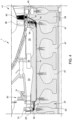
- FIG 2 is a schematic enlarged view of the portion II of figure 1 .
- Figure 2 discloses a downstream portion of the compressor 30 and an upstream portion of the turbine 41.
- figure 2 discloses the two last rows of compressor vanes 31, the last row of compressor blades 32, the first row of turbine vanes 36 and the first row of turbine blades 40.
- the two last rows of compressor vanes 31 are configured for axially guiding the air flow leaving the compressor. Downstream the compressor 30 a diffusor 33 is provided for guiding the compressed air towards the combustor.
- Reference 34 refers to a guide pipe configured for guiding part of the compressed air into a plenum 35 wherein the air can reach the first row of turbine vanes 36 for cooling reason.
- Figure 2 also discloses part of a rotor 37 in form of a plurality of adjacent disks.
- References 38 and 39 refer respectively to a rotor disk supporting the last row of compressing blades 32 and to a rotor disk supporting the first row of turbine blades 40.
- the rotor 37 is coupled to a rotor cover 42. This rotor cover and the corresponding portion of the rotor 37 defines an annulus 43, i.e. a volume closed upstream by an upstream seal 44 and downstream by a downstream seal 45.
- the annulus 43 is fed by cooling air and these seals 44 45 are configured for allowing an air leakage towards the last row of compressor vanes 31 and downstream the first row of turbine vanes 36 respectively for purging and sealing purposes.
- the cooling air fed in the annulus 43 is part of the compressed air passing by the pipe 34. Indeed, between the pipe 34 and the annulus 43 a swirl line 46 is provided for feeding the air to the annulus 43 and for imposing to the air a swirl effect.
- each couple of adjacent rotor disks are shaped to define cooling volumes 47.
- Reference 48 refers to the cooling volume partially obtained in the rotor disk 39 supporting the first row of turbine blades 40.
- axially channels are provided 49 for allowing the cooling air entering an upstream cooling volume 47 to reaches the cooling volume 48 and from there the first row of blade 40 via a discharge line 50.
- Reference 51 refers to a line connecting the annulus 43 to an upstream cooling volume 47.
- FIG 3 is a schematic enlarged view of the portion II of figure 1 duly modified according to the present invention.
- the same components disclosed in figure 2 have been represented in figure 3 with the same numerical referral.
- the annulus 43 and the diffuser 33/plenum 35 are not in fluid connection. Indeed, the annulus 43 is fed by compresses air spilled directed from the compressor, in this example directly upstream the last two rows of vanes 31 and downstream the last compressor row of blades 32.
- the inlet portion 52 of the annulus 43 is curved for minimizing the pressure loss.
- the cooling volume 48 obtained in the rotor disk 39 supporting the turbine blades 40 is directly fed by air leaving the annulus 43 and not coming from the upstream volumes 47 as per the previous figure.
- reference 51 refers to a discharge line connecting the cooling volume 48 to the annulus 43.
- the first turbine vanes 36 are fed with air via the seal 45 as per the previous figure.
- figure 4 discloses a different embodiment of a gas turbine not part of the invention.
- the same elements discloses in figures 3 and 4 have been represented with the same numerical referral.
- the two different independent solutions refer respectively the upstream portion and the downstream portion of the annulus 43, i.e. the gap fed by cooling air obtained between the rotor (in form of a plurality of rotor disks) and the rotor cover.
- the discharge line 51 have been removed and the annulus 43 has been prolonged up to the first rotor turbine disk where a radial space 54 is present between the firs turbine vane row 36 and the firs turbine blade row 40.
- the seal 45 has been replaced in this radial space 54.
- the first firs turbine blade row 40 is fed by air coming directly from the prolonged portion of the annulus 43 via the discharge line 55 and not more from the volume 48 (that become as the volumes 47 of figure 3 ).
- the line 55 is obtained in the first turbine disk 39 connecting directly the prolonged portion of the annulus 43 to the firs turbine blade row 40.
- the second difference at the upstream portion of the annulus 43 refer the inlet portion 52.
- inlet portion 52 is no more fed by air directly downstream the last compressor blade row 32 but it is fed by air directly downstream the second last compressor blade row 32'.
- the inlet portion 52 is realized in form of a line (i.e. a plurality of holes for instance) obtained in the last rotor compressor disk 53.
- these upstream and downstream solutions are independent, i.e. may be together or individually implemented.
Landscapes
- Engineering & Computer Science (AREA)
- Mechanical Engineering (AREA)
- General Engineering & Computer Science (AREA)
- Chemical & Material Sciences (AREA)
- Combustion & Propulsion (AREA)
- Physics & Mathematics (AREA)
- Fluid Mechanics (AREA)
- Structures Of Non-Positive Displacement Pumps (AREA)
Description
- The present invention relates to the technical field of the gas turbine assemblies for power plant. As known, in these assemblies an incoming air flow is compressed in a compressor and then mixed with fuel (gas fuel and/or oil fuel) in a combustor to produce a hot gas flow to be expanded in a turbine. The rotation of the turbine generates a rotating work on a rotor in turn connected to a generator for power production. It is known to use part of the compressed air for cooling hot elements of the assembly, wherein this cooling air by-passes the combustion and is guided towards, for instance, the rotor cover and turbine blades. In this technical field, the present invention addresses the problem of how to improve the rotor and turbine cooling by using spilled compressed air.
- As known, a gas turbine assembly for power plant comprises a compressor unit, a combustor unit and a turbine unit. The compressor unit is configured for compressing incoming air supplied at a compressor inlet. The compressed air leaving the compressor unit flows into a closed volume (called "plenum") and from there into the combustor unit. This combustor unit comprises usually a plurality of burners configured for injecting fuel (at least one type of fuel) into the compressed air flow. The mixture of fuel and compressed air enters a combustion chamber where this mixture ignites. The resulting hot gas flow leaves the combustion chamber and flows by the turbine unit performing a rotating work on a rotor connected to a generator. Usually the same rotor, that could be made as a single piece or in form of a plurality of adjacent rotor disks, supports also the rotating parts of the compressor assembly and it defines the main axis of the system. As known, the turbine unit and the compressor unit comprise a plurality of rows of rotating blades that are interposed by a plurality of rows of stator vanes. The rotating blades are supported by the rotor whereas the stator vanes are supported by a casing (called "vane carrier") that is concentric and surrounding the gas turbine assembly.
- In order to achieve a high efficiency, the hot gas flow has to have a very high turbine inlet temperature. However, in general this high temperature involves an undesired high NOx emission level. In order to reduce this emission and to increase operational flexibility without decreasing the efficiency, a so called "sequential" gas turbine is particularly suitable. In general, a sequential gas turbine performs two combustion stages in series. Today at least two different kinds of sequential gas turbines are known. According to a first embodiment, the gas turbine comprises a first combustor and a second combustor that are annular shaped and are physically separated by a turbine, called high pressure turbine. Downstream the second combustor a second turbine is provided (called low pressure turbine).
- According to a second embodiment, the sequential gas turbine is not provided with the high-pressure turbine and the combustor assembly is realized in form of a plurality of can-combustors wherein each can-combustor comprises a first combustor and a second combustor arranged directly one downstream the other inside a common casing can-shaped. These two examples of gas turbine assemblies have been cited only as non-limiting examples wherein the present invention can be applied. Indeed, as preferred example of gas turbine suitable to be improved by the present invention, the gas turbine assembly may involve a single stage of combustion with a single annular combustion chamber.
- As known in this technical field, the terms "circumferential, radial, axial, outer and inner" refer to the rotor or assembly axis (that is parallel to the main air/hot gas flow). The terms "downstream and upstream" refer to the main direction of the air/hot gas flowing from the compressor to the turbine.
- For cooling reasons it is common practice to use part of the compressed air wherein this cooling air by-passes the combustor and is fed to some hot components to be cooled. According to the prior art practice, that can be represented for instance by the enclosed
figure 2 disclosing an Applicant solution or by the disclosure of the prior art documentEP3006668 , the compressed air is fed by the compressor outlet to a diffuser and from there to a plenum before entering the combustor. According to the prior art practice, part of the compressor air flowing into the diffusor is spilled from the main flow and directed by a swirl line towards an annulus extending from the compressor to the turbine and provided between the rotor and a rotor cover. With the term "swirl line" we mean a plurality of channels configured to apply a swirl to the spilled air flow that before leaving the compressor has been axially forced by the two last row of compressor vanes. According tofigure 2 , the a line is provided to connect a guide tube, arranged between the diffuser and a plenum, to the annulus. The annulus offigure 2 is closed downstream and upstream by seals that are configured for allowing a leakage of air respectively towards the last and/or the second last row of compressor vanes for purging purposes and towards the first row turbine vanes for sealing purposes. From the annulus the swirled spilled air is fed to a volume obtained inside the rotor and from there is directed to the first row of turbine blades. As disclosed infigure 2 , the rotor comprises a plurality of adjacent disks wherein each couple of adjacent disks (at least between the compressor and the turbine) form a cooling volume. In this example, the swirled spilled air is fed to a rotor volume substantially arranged in a middle position of the rotor and from there via axial channels flow towards the rotor disk supporting the first row of blades. A discharge line is provided for feeding the air to the blades from this cooling volume. - According to the disclosure of
EP3006668 , the annulus extending from the compressor to the turbine is divided in two adjacent sub-annulus volumes divided by a seal. As for the previous example, the downstream end of the downstream sub-annulus is provided with a seal configured for allowing a leakage of the air towards the first row of turbine vanes. This downstream sub-annulus is connected to the plenum by a first swirl line (reference 12) so that the compressed air fed into the plenum by the diffusor can enter the downstream sub-annulus. A downstream discharge line (reference 15) is provided for connecting the downstream sub-annulus to a rotor volume obtained in the rotor disk supporting the first row of turbine blades. Indeed, from this rotor volume the air reached the first row of turbine blades. The upstream sub-annulus is connected to the plenum by an upstream or second swirl line (reference 11) so that the compressed air fed into the plenum by the diffusor can enter the upstream sub-annulus. The upstream end of the upstream sub-annulus is connected to the compressor so that, after cooling the rotor, the air is again introduced in the main flow leaving the compressor. - Thus, in both prior art disclosures above described the diffusor or the plenum are in fluid connection via swirl lines to the annulus. The fact of providing the assembly with these swirl lines involves some drawbacks in terms of mechanical processing required. Moreover, the high numbers of deviations imposed to the air flow between the compressor to the turbine generates an high pressure loss that implies an higher amount of air to be used for cooling.
-
EP3037674 relates to a guide vane element for use in a turbo compressor of such an engine and to a method for cooling components of the engine. -
US2012087784 relates to gas turbine systems, and more particularly to inducers for supplying cooling medium to various components in a gas turbine system. -
EP3093432 relates to the technology of gas turbines, in particular to a method for cooling a gas turbine. -
EP3147451 relates a system for cooling a gas turbine, which is capable of improving the efficiency of a gas turbine by individually supplying cooling air to each of a plurality of turbine disks. - The invention relates to a gas turbine assembly for power plant according to
claim 1. - Preferably, the compressor comprises an outlet and a diffuser downstream connected to the compressor outlet. This diffuser is configured for guiding the air leaving the compressor towards a combustor unit. Usually the two last rows of vanes (the last row is called "outlet guide vanes") are configured for forcing the flow along the axial direction. The single annulus of the invention is directly connected to the compressor in an upstream position with respect to the compressor outlet (preferably downstream the last rotating row of compressor blades) and both the diffuser and the plenum are fluidly separated from the single annulus (no line is present between diffuser/plenum and the single annulus). Thus, according the invention the air is fed to the annulus directly spilled from the compressor and not from the diffuser or the plenum downstream the compressor. In this way the air used for cooling is itself provided with a swirl and therefore no additional swirl lines or devices are required for this scope.
- Preferably, the compressor outlet comprises two rows of vanes configured for axially guiding the air before leaving the compressor. In this configuration, the single annulus is connected to the compressor in a position directly upstream with respect to these two last rows of vanes.
- Preferably, the rotor comprises a plurality of adjacent disks and the cooling volume foregoing mentioned is obtained between two adjacent rotor disks wherein the downstream disk of this couple supports the first row of turbine blades.
- Preferably, the single annulus comprises a curved inlet portion upstream connected to the compressor.
- The invention has been foregoing described in structural terms. However, the invention is also defined in terms of a method of operating the gas turbine assembly according to
claim 8. - This method allows to understand the differences between the invention and the prior art. In the cited prior document the annulus is fluidly connected to the compressor but this connection is used to fed air from the annulus into the compressor and not vice-versa as the present invention.
- Thus, as a not limiting list of the advantage of the invention, the cooling of the rotor or rotor disks between the compressor and the turbine are improved and a less amount of air is required for cooling the first row of turbine blades due to a higher swirl preserved from the compressor to the turbine. Indeed, a higher swirl means a lower relative temperature of the air with respect to the rotating parts of the assembly.
- It is to be understood that both the foregoing general description and the following detailed description are exemplary, and are intended to provide further explanation of the invention as claimed. Other advantages and features of the invention will be apparent from the following description, drawings and claims.
- The features of the invention believed to be novel are set forth with particularity in the appended claims.
- Further benefits and advantages of the present invention will become apparent after a careful reading of the detailed description with appropriate reference to the accompanying drawings.
- The invention itself, however, may be best understood by reference to the following detailed description of the invention, which describes an exemplary embodiment of the invention, taken in conjunction with the accompanying drawings, in which:
-
figure 1 is a schematic view of a not-limiting example of a gas turbine that can be improved by the present invention; -
figure 2 is a schematic enlarged view of the portion II offigure 1 wherein an example of the prior art is disclosed; -
figure 3 is a schematic enlarged view of the portion II offigure 1 duly modified according to the present invention; -
figure 4 discloses a different embodiment of gas turbine not part of the invention. - In cooperation with attached drawings, the technical contents and detailed description of the present invention are described thereinafter according to preferred embodiments, being not used to limit its executing scope. Any equivalent variation and modification made according to appended claims is all covered by the claims claimed by the present invention.
- Reference will now be made to the drawing figures to describe the present invention in detail.
- Reference is made to
figure 1 which is a schematic view of a not-limiting example of a gas turbine assembly for power plant that can be improved by the present invention. Infigure 1 thegas turbine assembly 1 comprises acompressor unit 3, acombustion unit 4, aturbine unit 5 and a generator (for simplicity, not shown in the attached figures). The rotating parts of thecompressor 3,turbine 5 and generator are supported by acommon rotor 8, which is housed in acasings 9 and extends along an axis A. Infigure 1 , therotor 8 comprises afront shaft 10, arear shaft 13 and in between a plurality ofadjacent rotor disks 15 clamped as a pack by acentral tie rod 14. As an alternative, the rotor disks may be welded together. Eachrotor disk 15 supports a row ofblades 16. Thecasing 9 comprises a plurality of stator rows ofvanes 22 alternated with the rotating rows ofblades 16. - Reference is made to
figure 2 that is a schematic enlarged view of the portion II offigure 1 . This view refers to the prior art practice.Figure 2 discloses a downstream portion of thecompressor 30 and an upstream portion of theturbine 41. In particular,figure 2 discloses the two last rows ofcompressor vanes 31, the last row ofcompressor blades 32, the first row ofturbine vanes 36 and the first row ofturbine blades 40. As known, the two last rows ofcompressor vanes 31 are configured for axially guiding the air flow leaving the compressor. Downstream the compressor 30 adiffusor 33 is provided for guiding the compressed air towards the combustor.Reference 34 refers to a guide pipe configured for guiding part of the compressed air into aplenum 35 wherein the air can reach the first row ofturbine vanes 36 for cooling reason.Figure 2 also discloses part of arotor 37 in form of a plurality of adjacent disks.References blades 32 and to a rotor disk supporting the first row ofturbine blades 40. In the portion between the compressor outlet and the turbine inlet, therotor 37 is coupled to arotor cover 42. This rotor cover and the corresponding portion of therotor 37 defines anannulus 43, i.e. a volume closed upstream by anupstream seal 44 and downstream by adownstream seal 45. Theannulus 43 is fed by cooling air and theseseals 44 45 are configured for allowing an air leakage towards the last row ofcompressor vanes 31 and downstream the first row ofturbine vanes 36 respectively for purging and sealing purposes. The cooling air fed in theannulus 43 is part of the compressed air passing by thepipe 34. Indeed, between thepipe 34 and the annulus 43 aswirl line 46 is provided for feeding the air to theannulus 43 and for imposing to the air a swirl effect. As disclosed infigure 2 , each couple of adjacent rotor disks are shaped to definecooling volumes 47.Reference 48 refers to the cooling volume partially obtained in therotor disk 39 supporting the first row ofturbine blades 40. Between thiscooling volume 48 and theupstream cooling volumes 47 axially channels are provided 49 for allowing the cooling air entering anupstream cooling volume 47 to reaches the coolingvolume 48 and from there the first row ofblade 40 via adischarge line 50.Reference 51 refers to a line connecting theannulus 43 to anupstream cooling volume 47. - Reference is now made to
figure 3 that is a schematic enlarged view of the portion II offigure 1 duly modified according to the present invention. In this sense the same components disclosed infigure 2 have been represented infigure 3 with the same numerical referral. According tofigure 3 , and to the invention, theannulus 43 and thediffuser 33/plenum 35 are not in fluid connection. Indeed, theannulus 43 is fed by compresses air spilled directed from the compressor, in this example directly upstream the last two rows ofvanes 31 and downstream the last compressor row ofblades 32. Preferably, as presented, theinlet portion 52 of theannulus 43 is curved for minimizing the pressure loss. The coolingvolume 48 obtained in therotor disk 39 supporting theturbine blades 40 is directly fed by air leaving theannulus 43 and not coming from theupstream volumes 47 as per the previous figure. Indeed,reference 51 refers to a discharge line connecting the coolingvolume 48 to theannulus 43. Thefirst turbine vanes 36 are fed with air via theseal 45 as per the previous figure. - Finally,
figure 4 discloses a different embodiment of a gas turbine not part of the invention. The same elements discloses infigures 3 and4 have been represented with the same numerical referral. The two different independent solutions refer respectively the upstream portion and the downstream portion of theannulus 43, i.e. the gap fed by cooling air obtained between the rotor (in form of a plurality of rotor disks) and the rotor cover. At the downstream portion, thedischarge line 51 have been removed and theannulus 43 has been prolonged up to the first rotor turbine disk where aradial space 54 is present between the firsturbine vane row 36 and the firsturbine blade row 40. As disclosed theseal 45 has been replaced in thisradial space 54. Infigure 4 the first firsturbine blade row 40 is fed by air coming directly from the prolonged portion of theannulus 43 via thedischarge line 55 and not more from the volume 48 (that become as thevolumes 47 offigure 3 ). Indeed, infigure 4 theline 55 is obtained in thefirst turbine disk 39 connecting directly the prolonged portion of theannulus 43 to the firsturbine blade row 40. The second difference at the upstream portion of theannulus 43 refer theinlet portion 52. In thiscase inlet portion 52 is no more fed by air directly downstream the lastcompressor blade row 32 but it is fed by air directly downstream the second last compressor blade row 32'. In this case theinlet portion 52 is realized in form of a line (i.e. a plurality of holes for instance) obtained in the lastrotor compressor disk 53. As foregoing mentioned, these upstream and downstream solutions are independent, i.e. may be together or individually implemented. - Although the invention has been explained in relation to its preferred embodiment(s) as mentioned above, it is to be understood that many other possible modifications and variations can be made without departing from the scope of the present invention. It is, therefore, contemplated that the appended claim or claims will cover such modifications and variations that fall within the true scope of the invention.
Claims (13)
- A gas turbine assembly for power plant, the gas turbine (1) comprising:- a rotor (37) having an axis (A);- a compressor (30);- a turbine (41);- a rotor cover (42);- a single annulus (43) between the rotor (37) and the rotor cover (42);whereinthe single annulus (43) is connected upstream to the compressor (30) for being fed by air spilled from the compressor (30) and downstream to discharge lines (50, 51, 55) for feeding the compressor air to the turbine (41);characterized in thata first discharge line (51) is downstream connected to a cooling volume (48) obtained inside the rotor (37) and from there the air is fed to the turbine (41) via a second discharge line (50);wherein the turbine (41) comprises a first row of vanes (36); at the downstream end of the single annulus (45) between the rotor (37) and the rotor cover (42) being provided a seal (45) configured for allowing leakage of air from the annulus (43) towards a stator-rotor cavity between the first row of turbine vanes (36) and the first row of turbine blades (40).
- Gas turbine assembly according to any foregoing claims, wherein the compressor (30) comprises an outlet and a diffuser (33) downstream connected to the compressor outlet; the single annulus (43) being connected to the compressor (30) in a position upstream with respect to the compressor outlet.
- Gas turbine assembly according to claim 2, wherein downstream the last row of compressor blades (32) the compressor outlet comprises one or two rows of vanes (31) configured for axially guiding the compressor air; the single annulus (43) being connected to the compressor in a position directly downstream the last row of compressor blades (32).
- Gas turbine assembly according to claim 2, wherein the compressor comprises a second last row of compressor blades (32); the single annulus (43) being connected to the compressor in a position directly downstream the second last row of compressor blades.
- Gas turbine assembly according to claim 2 or 3, wherein the diffuser (33) is downstream connected to a plenum (35), the plenum (35) being fluidly separated from the single annulus (43).
- Gas turbine assembly according to any one of the foregoing claims from 1 to 5, wherein the rotor (37) comprises a plurality of adjacent disks (38, 39), the cooling volume (48) being obtained between two adjacent rotor disks wherein the downstream disk (39) of this couple of disks supports a first row of turbine blades (40).
- Gas turbine assembly according to any one of the foregoing claims, wherein the single annulus (43) comprises a curved inlet portion (52) upstream connected to the compressor (30).
- Method for operating a gas turbine assembly for power plant, the method comprising the step of:a) providing a gas turbine assembly (1) comprising:- a rotor (37) having an axis;- a compressor (30);- a turbine (41);- a rotor cover (42);- a single annulus (43) between the rotor (37) and the rotor cover (42), the single annulus (43) being connected upstream to the compressor (30) and downstream to a discharge lines (50, 51, 55) connecting the annulus (43) to the turbine (41);b) spilling air from the compressor (30) and feeding the spilled air directly into the single annulus (43);
characterized in that the method also comprises the step ofc) feeding the spilled air from the single annulus (43) into a cooling volume (48) obtained in the rotor via the first discharge line (51) and from there via a second discharge line (50) to the turbine (41) ;
wherein the turbine of step a) comprises first row of turbine vanes (36); according to step a) between the rotor (37) and the rotor cover (42) at the single annulus outlet a seal (45) is provided; the method comprises also the step of:
d) leaking air from the annulus (43) via the seal (45) towards a stator-rotor cavity between the first row of turbine vanes (36) and the first row of turbine blades (40). - Method as claimed in claim 8, wherein the compressor of step a) comprises an outlet downstream connected to a diffuser (33); the step b) being performed by spilling air from the compressor (30) in a position upstream with respect to the compressor outlet.
- Method as claimed in claim 9, wherein the compressor outlet of step a) comprises two end rows of compressor vanes (31) configured for axially guiding the compressor air; the step b) being performed by spilling air from the compressor (30) upstream with respect to these two end rows of vanes (31).
- Method as claimed in any one of the foregoing claims from 8 to 10, wherein the turbine of step a) comprises a first row of turbine blades (40); the step c) being performed by feeding the spilled air to the first row of turbine blades (40).
- Method as claimed in claim 10 or 11, wherein the rotor of step c) comprises a plurality of adjacent disks (38, 39), the cooling volume (48) being obtained between two adjacent rotor disks wherein the downstream disk (39) of these couple of disks supports the first row of turbine blades (40).
- Method as claimed in any one of the foregoing claims from 8 to 12, wherein the single annulus (43) of step a) between the rotor cover and the rotor comprises a curved inlet portion (52) upstream connected to the compressor (30).
Priority Applications (2)
| Application Number | Priority Date | Filing Date | Title |
|---|---|---|---|
| EP21425053.2A EP4174286B1 (en) | 2021-10-29 | 2021-10-29 | Gas turbine assembly for power plant with improved rotor and turbine blades cooling and method for operating this gas turbine assembly |
| CN202211334194.XA CN116066243A (en) | 2021-10-29 | 2022-10-28 | Gas turbine assembly for a power facility and method of operation thereof |
Applications Claiming Priority (1)
| Application Number | Priority Date | Filing Date | Title |
|---|---|---|---|
| EP21425053.2A EP4174286B1 (en) | 2021-10-29 | 2021-10-29 | Gas turbine assembly for power plant with improved rotor and turbine blades cooling and method for operating this gas turbine assembly |
Publications (2)
| Publication Number | Publication Date |
|---|---|
| EP4174286A1 EP4174286A1 (en) | 2023-05-03 |
| EP4174286B1 true EP4174286B1 (en) | 2024-12-04 |
Family
ID=79231078
Family Applications (1)
| Application Number | Title | Priority Date | Filing Date |
|---|---|---|---|
| EP21425053.2A Active EP4174286B1 (en) | 2021-10-29 | 2021-10-29 | Gas turbine assembly for power plant with improved rotor and turbine blades cooling and method for operating this gas turbine assembly |
Country Status (2)
| Country | Link |
|---|---|
| EP (1) | EP4174286B1 (en) |
| CN (1) | CN116066243A (en) |
Families Citing this family (1)
| Publication number | Priority date | Publication date | Assignee | Title |
|---|---|---|---|---|
| IT202300014751A1 (en) * | 2023-07-13 | 2025-01-13 | Nuovo Pignone Srl | POWER-GENERATING TURBOMACHINE WITH IMPROVED COOLANT EXTRACTION FROM THE ROTOR CAVITY |
Family Cites Families (5)
| Publication number | Priority date | Publication date | Assignee | Title |
|---|---|---|---|---|
| US8529195B2 (en) * | 2010-10-12 | 2013-09-10 | General Electric Company | Inducer for gas turbine system |
| EP3006668A1 (en) | 2014-10-07 | 2016-04-13 | Siemens Aktiengesellschaft | Gas turbine with two vortex feeds for cooling the rotor |
| EP3037674A1 (en) * | 2014-12-22 | 2016-06-29 | Alstom Technology Ltd | Engine and method for operating said engine |
| EP3093432B1 (en) * | 2015-05-15 | 2021-04-21 | Ansaldo Energia Switzerland AG | Method for cooling a gas turbine and gas turbine for conducting said method |
| KR101665887B1 (en) * | 2015-09-23 | 2016-10-12 | 두산중공업 주식회사 | Cooling system of the gas turbine |
-
2021
- 2021-10-29 EP EP21425053.2A patent/EP4174286B1/en active Active
-
2022
- 2022-10-28 CN CN202211334194.XA patent/CN116066243A/en active Pending
Also Published As
| Publication number | Publication date |
|---|---|
| CN116066243A (en) | 2023-05-05 |
| EP4174286A1 (en) | 2023-05-03 |
Similar Documents
| Publication | Publication Date | Title |
|---|---|---|
| US8381533B2 (en) | Direct transfer axial tangential onboard injector system (TOBI) with self-supporting seal plate | |
| US8727703B2 (en) | Gas turbine engine | |
| US4719747A (en) | Apparatus for optimizing the blade and sealing slots of a compressor of a gas turbine | |
| US8087249B2 (en) | Turbine cooling air from a centrifugal compressor | |
| US20170248155A1 (en) | Centrifugal compressor diffuser passage boundary layer control | |
| CN110185501B (en) | Gas turbine engine with guide vanes having cooling inlets | |
| US20130280040A1 (en) | Cooling assembly for a gas turbine system | |
| US11092028B2 (en) | Tip balance slits for turbines | |
| EP4174286B1 (en) | Gas turbine assembly for power plant with improved rotor and turbine blades cooling and method for operating this gas turbine assembly | |
| CN108266231B (en) | Last turbine rotor disk for a gas turbine, rotor and gas turbine | |
| JP3977780B2 (en) | gas turbine | |
| US10815829B2 (en) | Turbine housing assembly | |
| KR102440257B1 (en) | Sealing assembly and turbo-machine comprising the same | |
| EP3822458B1 (en) | Gas turbine for power plant and method for retrofitting a gas turbine for power plant already in service | |
| JP2005009410A (en) | Gas turbine and rotor seal air introduction method | |
| EP4183983B1 (en) | Gas turbine assembly for power plant having a low wear membrane seal arrangement for sealing the combustor to turbine interface, and method for retrofitting a gas turbine assembly | |
| JP7463203B2 (en) | Turbine rotor and axial flow turbine | |
| EP4019753B1 (en) | Power plant comprising a gas turbine assembly and a steam turbine assembly for forming a combined cycle and method for operating this power plant | |
| KR102791918B1 (en) | Rotor having double wedge seal module, turbine and turbomachine comprising the same | |
| EP4198265A1 (en) | Vane for a gas turbine assembly for power plant and gas turbine assembly for power plant comprising such a vane | |
| US20240401527A1 (en) | Gas turbine with diffuser steam injection into a combustor | |
| US11274555B2 (en) | Turbine rotor | |
| CA2992684C (en) | Turbine housing assembly | |
| US10927706B2 (en) | Intercooled tangential air injector for gas turbine engines | |
| US20210123358A1 (en) | Spline seal for disk post |
Legal Events
| Date | Code | Title | Description |
|---|---|---|---|
| PUAI | Public reference made under article 153(3) epc to a published international application that has entered the european phase |
Free format text: ORIGINAL CODE: 0009012 |
|
| STAA | Information on the status of an ep patent application or granted ep patent |
Free format text: STATUS: THE APPLICATION HAS BEEN PUBLISHED |
|
| AK | Designated contracting states |
Kind code of ref document: A1 Designated state(s): AL AT BE BG CH CY CZ DE DK EE ES FI FR GB GR HR HU IE IS IT LI LT LU LV MC MK MT NL NO PL PT RO RS SE SI SK SM TR |
|
| STAA | Information on the status of an ep patent application or granted ep patent |
Free format text: STATUS: REQUEST FOR EXAMINATION WAS MADE |
|
| 17P | Request for examination filed |
Effective date: 20231103 |
|
| RBV | Designated contracting states (corrected) |
Designated state(s): AL AT BE BG CH CY CZ DE DK EE ES FI FR GB GR HR HU IE IS IT LI LT LU LV MC MK MT NL NO PL PT RO RS SE SI SK SM TR |
|
| GRAP | Despatch of communication of intention to grant a patent |
Free format text: ORIGINAL CODE: EPIDOSNIGR1 |
|
| STAA | Information on the status of an ep patent application or granted ep patent |
Free format text: STATUS: GRANT OF PATENT IS INTENDED |
|
| P01 | Opt-out of the competence of the unified patent court (upc) registered |
Effective date: 20240430 |
|
| GRAJ | Information related to disapproval of communication of intention to grant by the applicant or resumption of examination proceedings by the epo deleted |
Free format text: ORIGINAL CODE: EPIDOSDIGR1 |
|
| STAA | Information on the status of an ep patent application or granted ep patent |
Free format text: STATUS: REQUEST FOR EXAMINATION WAS MADE |
|
| INTG | Intention to grant announced |
Effective date: 20240516 |
|
| GRAP | Despatch of communication of intention to grant a patent |
Free format text: ORIGINAL CODE: EPIDOSNIGR1 |
|
| STAA | Information on the status of an ep patent application or granted ep patent |
Free format text: STATUS: GRANT OF PATENT IS INTENDED |
|
| INTC | Intention to grant announced (deleted) | ||
| INTG | Intention to grant announced |
Effective date: 20240711 |
|
| GRAS | Grant fee paid |
Free format text: ORIGINAL CODE: EPIDOSNIGR3 |
|
| GRAA | (expected) grant |
Free format text: ORIGINAL CODE: 0009210 |
|
| STAA | Information on the status of an ep patent application or granted ep patent |
Free format text: STATUS: THE PATENT HAS BEEN GRANTED |
|
| AK | Designated contracting states |
Kind code of ref document: B1 Designated state(s): AL AT BE BG CH CY CZ DE DK EE ES FI FR GB GR HR HU IE IS IT LI LT LU LV MC MK MT NL NO PL PT RO RS SE SI SK SM TR |
|
| REG | Reference to a national code |
Ref country code: CH Ref legal event code: EP |
|
| REG | Reference to a national code |
Ref country code: DE Ref legal event code: R096 Ref document number: 602021022803 Country of ref document: DE |
|
| REG | Reference to a national code |
Ref country code: IE Ref legal event code: FG4D |
|
| REG | Reference to a national code |
Ref country code: LT Ref legal event code: MG9D |
|
| REG | Reference to a national code |
Ref country code: NL Ref legal event code: MP Effective date: 20241204 |
|
| PG25 | Lapsed in a contracting state [announced via postgrant information from national office to epo] |
Ref country code: HR Free format text: LAPSE BECAUSE OF FAILURE TO SUBMIT A TRANSLATION OF THE DESCRIPTION OR TO PAY THE FEE WITHIN THE PRESCRIBED TIME-LIMIT Effective date: 20241204 |
|
| PG25 | Lapsed in a contracting state [announced via postgrant information from national office to epo] |
Ref country code: FI Free format text: LAPSE BECAUSE OF FAILURE TO SUBMIT A TRANSLATION OF THE DESCRIPTION OR TO PAY THE FEE WITHIN THE PRESCRIBED TIME-LIMIT Effective date: 20241204 |
|
| PG25 | Lapsed in a contracting state [announced via postgrant information from national office to epo] |
Ref country code: BG Free format text: LAPSE BECAUSE OF FAILURE TO SUBMIT A TRANSLATION OF THE DESCRIPTION OR TO PAY THE FEE WITHIN THE PRESCRIBED TIME-LIMIT Effective date: 20241204 |
|
| PG25 | Lapsed in a contracting state [announced via postgrant information from national office to epo] |
Ref country code: ES Free format text: LAPSE BECAUSE OF FAILURE TO SUBMIT A TRANSLATION OF THE DESCRIPTION OR TO PAY THE FEE WITHIN THE PRESCRIBED TIME-LIMIT Effective date: 20241204 |
|
| PG25 | Lapsed in a contracting state [announced via postgrant information from national office to epo] |
Ref country code: NO Free format text: LAPSE BECAUSE OF FAILURE TO SUBMIT A TRANSLATION OF THE DESCRIPTION OR TO PAY THE FEE WITHIN THE PRESCRIBED TIME-LIMIT Effective date: 20250304 |
|
| PG25 | Lapsed in a contracting state [announced via postgrant information from national office to epo] |
Ref country code: LV Free format text: LAPSE BECAUSE OF FAILURE TO SUBMIT A TRANSLATION OF THE DESCRIPTION OR TO PAY THE FEE WITHIN THE PRESCRIBED TIME-LIMIT Effective date: 20241204 Ref country code: GR Free format text: LAPSE BECAUSE OF FAILURE TO SUBMIT A TRANSLATION OF THE DESCRIPTION OR TO PAY THE FEE WITHIN THE PRESCRIBED TIME-LIMIT Effective date: 20250305 |
|
| PG25 | Lapsed in a contracting state [announced via postgrant information from national office to epo] |
Ref country code: RS Free format text: LAPSE BECAUSE OF FAILURE TO SUBMIT A TRANSLATION OF THE DESCRIPTION OR TO PAY THE FEE WITHIN THE PRESCRIBED TIME-LIMIT Effective date: 20250304 |
|
| PG25 | Lapsed in a contracting state [announced via postgrant information from national office to epo] |
Ref country code: NL Free format text: LAPSE BECAUSE OF FAILURE TO SUBMIT A TRANSLATION OF THE DESCRIPTION OR TO PAY THE FEE WITHIN THE PRESCRIBED TIME-LIMIT Effective date: 20241204 |
|
| REG | Reference to a national code |
Ref country code: AT Ref legal event code: MK05 Ref document number: 1748366 Country of ref document: AT Kind code of ref document: T Effective date: 20241204 |
|
| PG25 | Lapsed in a contracting state [announced via postgrant information from national office to epo] |
Ref country code: SM Free format text: LAPSE BECAUSE OF FAILURE TO SUBMIT A TRANSLATION OF THE DESCRIPTION OR TO PAY THE FEE WITHIN THE PRESCRIBED TIME-LIMIT Effective date: 20241204 |
|
| PG25 | Lapsed in a contracting state [announced via postgrant information from national office to epo] |
Ref country code: PL Free format text: LAPSE BECAUSE OF FAILURE TO SUBMIT A TRANSLATION OF THE DESCRIPTION OR TO PAY THE FEE WITHIN THE PRESCRIBED TIME-LIMIT Effective date: 20241204 |
|
| PG25 | Lapsed in a contracting state [announced via postgrant information from national office to epo] |
Ref country code: IS Free format text: LAPSE BECAUSE OF FAILURE TO SUBMIT A TRANSLATION OF THE DESCRIPTION OR TO PAY THE FEE WITHIN THE PRESCRIBED TIME-LIMIT Effective date: 20250404 |
|
| PG25 | Lapsed in a contracting state [announced via postgrant information from national office to epo] |
Ref country code: PT Free format text: LAPSE BECAUSE OF FAILURE TO SUBMIT A TRANSLATION OF THE DESCRIPTION OR TO PAY THE FEE WITHIN THE PRESCRIBED TIME-LIMIT Effective date: 20250404 |
|
| PG25 | Lapsed in a contracting state [announced via postgrant information from national office to epo] |
Ref country code: EE Free format text: LAPSE BECAUSE OF FAILURE TO SUBMIT A TRANSLATION OF THE DESCRIPTION OR TO PAY THE FEE WITHIN THE PRESCRIBED TIME-LIMIT Effective date: 20241204 |
|
| PG25 | Lapsed in a contracting state [announced via postgrant information from national office to epo] |
Ref country code: RO Free format text: LAPSE BECAUSE OF FAILURE TO SUBMIT A TRANSLATION OF THE DESCRIPTION OR TO PAY THE FEE WITHIN THE PRESCRIBED TIME-LIMIT Effective date: 20241204 Ref country code: AT Free format text: LAPSE BECAUSE OF FAILURE TO SUBMIT A TRANSLATION OF THE DESCRIPTION OR TO PAY THE FEE WITHIN THE PRESCRIBED TIME-LIMIT Effective date: 20241204 |
|
| PG25 | Lapsed in a contracting state [announced via postgrant information from national office to epo] |
Ref country code: SK Free format text: LAPSE BECAUSE OF FAILURE TO SUBMIT A TRANSLATION OF THE DESCRIPTION OR TO PAY THE FEE WITHIN THE PRESCRIBED TIME-LIMIT Effective date: 20241204 |
|
| PG25 | Lapsed in a contracting state [announced via postgrant information from national office to epo] |
Ref country code: CZ Free format text: LAPSE BECAUSE OF FAILURE TO SUBMIT A TRANSLATION OF THE DESCRIPTION OR TO PAY THE FEE WITHIN THE PRESCRIBED TIME-LIMIT Effective date: 20241204 |
|
| REG | Reference to a national code |
Ref country code: DE Ref legal event code: R097 Ref document number: 602021022803 Country of ref document: DE |
|
| PG25 | Lapsed in a contracting state [announced via postgrant information from national office to epo] |
Ref country code: SE Free format text: LAPSE BECAUSE OF FAILURE TO SUBMIT A TRANSLATION OF THE DESCRIPTION OR TO PAY THE FEE WITHIN THE PRESCRIBED TIME-LIMIT Effective date: 20241204 |
|
| PG25 | Lapsed in a contracting state [announced via postgrant information from national office to epo] |
Ref country code: DK Free format text: LAPSE BECAUSE OF FAILURE TO SUBMIT A TRANSLATION OF THE DESCRIPTION OR TO PAY THE FEE WITHIN THE PRESCRIBED TIME-LIMIT Effective date: 20241204 |
|
| PLBE | No opposition filed within time limit |
Free format text: ORIGINAL CODE: 0009261 |
|
| STAA | Information on the status of an ep patent application or granted ep patent |
Free format text: STATUS: NO OPPOSITION FILED WITHIN TIME LIMIT |
|
| 26N | No opposition filed |
Effective date: 20250905 |
|
| PGFP | Annual fee paid to national office [announced via postgrant information from national office to epo] |
Ref country code: DE Payment date: 20251020 Year of fee payment: 5 |
|
| PGFP | Annual fee paid to national office [announced via postgrant information from national office to epo] |
Ref country code: IT Payment date: 20251031 Year of fee payment: 5 |