EP4174232A1 - Construction equipment - Google Patents
Construction equipment Download PDFInfo
- Publication number
- EP4174232A1 EP4174232A1 EP22203874.7A EP22203874A EP4174232A1 EP 4174232 A1 EP4174232 A1 EP 4174232A1 EP 22203874 A EP22203874 A EP 22203874A EP 4174232 A1 EP4174232 A1 EP 4174232A1
- Authority
- EP
- European Patent Office
- Prior art keywords
- electronic control
- control unit
- boom
- arm
- increase rate
- Prior art date
- Legal status (The legal status is an assumption and is not a legal conclusion. Google has not performed a legal analysis and makes no representation as to the accuracy of the status listed.)
- Granted
Links
Images



Classifications
-
- E—FIXED CONSTRUCTIONS
- E02—HYDRAULIC ENGINEERING; FOUNDATIONS; SOIL SHIFTING
- E02F—DREDGING; SOIL-SHIFTING
- E02F3/00—Dredgers; Soil-shifting machines
- E02F3/04—Dredgers; Soil-shifting machines mechanically-driven
- E02F3/28—Dredgers; Soil-shifting machines mechanically-driven with digging tools mounted on a dipper- or bucket-arm, i.e. there is either one arm or a pair of arms, e.g. dippers, buckets
- E02F3/36—Component parts
- E02F3/42—Drives for dippers, buckets, dipper-arms or bucket-arms
- E02F3/43—Control of dipper or bucket position; Control of sequence of drive operations
- E02F3/435—Control of dipper or bucket position; Control of sequence of drive operations for dipper-arms, backhoes or the like
- E02F3/437—Control of dipper or bucket position; Control of sequence of drive operations for dipper-arms, backhoes or the like providing automatic sequences of movements, e.g. linear excavation, keeping dipper angle constant
-
- E—FIXED CONSTRUCTIONS
- E02—HYDRAULIC ENGINEERING; FOUNDATIONS; SOIL SHIFTING
- E02F—DREDGING; SOIL-SHIFTING
- E02F3/00—Dredgers; Soil-shifting machines
- E02F3/04—Dredgers; Soil-shifting machines mechanically-driven
- E02F3/28—Dredgers; Soil-shifting machines mechanically-driven with digging tools mounted on a dipper- or bucket-arm, i.e. there is either one arm or a pair of arms, e.g. dippers, buckets
- E02F3/30—Dredgers; Soil-shifting machines mechanically-driven with digging tools mounted on a dipper- or bucket-arm, i.e. there is either one arm or a pair of arms, e.g. dippers, buckets with a dipper-arm pivoted on a cantilever beam, i.e. boom
- E02F3/32—Dredgers; Soil-shifting machines mechanically-driven with digging tools mounted on a dipper- or bucket-arm, i.e. there is either one arm or a pair of arms, e.g. dippers, buckets with a dipper-arm pivoted on a cantilever beam, i.e. boom working downwardly and towards the machine, e.g. with backhoes
-
- E—FIXED CONSTRUCTIONS
- E02—HYDRAULIC ENGINEERING; FOUNDATIONS; SOIL SHIFTING
- E02F—DREDGING; SOIL-SHIFTING
- E02F3/00—Dredgers; Soil-shifting machines
- E02F3/04—Dredgers; Soil-shifting machines mechanically-driven
- E02F3/28—Dredgers; Soil-shifting machines mechanically-driven with digging tools mounted on a dipper- or bucket-arm, i.e. there is either one arm or a pair of arms, e.g. dippers, buckets
- E02F3/36—Component parts
- E02F3/42—Drives for dippers, buckets, dipper-arms or bucket-arms
- E02F3/43—Control of dipper or bucket position; Control of sequence of drive operations
- E02F3/431—Control of dipper or bucket position; Control of sequence of drive operations for bucket-arms, front-end loaders, dumpers or the like
-
- E—FIXED CONSTRUCTIONS
- E02—HYDRAULIC ENGINEERING; FOUNDATIONS; SOIL SHIFTING
- E02F—DREDGING; SOIL-SHIFTING
- E02F9/00—Component parts of dredgers or soil-shifting machines, not restricted to one of the kinds covered by groups E02F3/00 - E02F7/00
- E02F9/20—Drives; Control devices
- E02F9/22—Hydraulic or pneumatic drives
- E02F9/2221—Control of flow rate; Load sensing arrangements
-
- E—FIXED CONSTRUCTIONS
- E02—HYDRAULIC ENGINEERING; FOUNDATIONS; SOIL SHIFTING
- E02F—DREDGING; SOIL-SHIFTING
- E02F3/00—Dredgers; Soil-shifting machines
- E02F3/04—Dredgers; Soil-shifting machines mechanically-driven
- E02F3/28—Dredgers; Soil-shifting machines mechanically-driven with digging tools mounted on a dipper- or bucket-arm, i.e. there is either one arm or a pair of arms, e.g. dippers, buckets
- E02F3/30—Dredgers; Soil-shifting machines mechanically-driven with digging tools mounted on a dipper- or bucket-arm, i.e. there is either one arm or a pair of arms, e.g. dippers, buckets with a dipper-arm pivoted on a cantilever beam, i.e. boom
-
- E—FIXED CONSTRUCTIONS
- E02—HYDRAULIC ENGINEERING; FOUNDATIONS; SOIL SHIFTING
- E02F—DREDGING; SOIL-SHIFTING
- E02F3/00—Dredgers; Soil-shifting machines
- E02F3/04—Dredgers; Soil-shifting machines mechanically-driven
- E02F3/28—Dredgers; Soil-shifting machines mechanically-driven with digging tools mounted on a dipper- or bucket-arm, i.e. there is either one arm or a pair of arms, e.g. dippers, buckets
- E02F3/36—Component parts
- E02F3/42—Drives for dippers, buckets, dipper-arms or bucket-arms
- E02F3/425—Drive systems for dipper-arms, backhoes or the like
-
- E—FIXED CONSTRUCTIONS
- E02—HYDRAULIC ENGINEERING; FOUNDATIONS; SOIL SHIFTING
- E02F—DREDGING; SOIL-SHIFTING
- E02F3/00—Dredgers; Soil-shifting machines
- E02F3/04—Dredgers; Soil-shifting machines mechanically-driven
- E02F3/28—Dredgers; Soil-shifting machines mechanically-driven with digging tools mounted on a dipper- or bucket-arm, i.e. there is either one arm or a pair of arms, e.g. dippers, buckets
- E02F3/36—Component parts
- E02F3/42—Drives for dippers, buckets, dipper-arms or bucket-arms
- E02F3/43—Control of dipper or bucket position; Control of sequence of drive operations
- E02F3/431—Control of dipper or bucket position; Control of sequence of drive operations for bucket-arms, front-end loaders, dumpers or the like
- E02F3/434—Control of dipper or bucket position; Control of sequence of drive operations for bucket-arms, front-end loaders, dumpers or the like providing automatic sequences of movements, e.g. automatic dumping or loading, automatic return-to-dig
-
- E—FIXED CONSTRUCTIONS
- E02—HYDRAULIC ENGINEERING; FOUNDATIONS; SOIL SHIFTING
- E02F—DREDGING; SOIL-SHIFTING
- E02F3/00—Dredgers; Soil-shifting machines
- E02F3/04—Dredgers; Soil-shifting machines mechanically-driven
- E02F3/28—Dredgers; Soil-shifting machines mechanically-driven with digging tools mounted on a dipper- or bucket-arm, i.e. there is either one arm or a pair of arms, e.g. dippers, buckets
- E02F3/36—Component parts
- E02F3/42—Drives for dippers, buckets, dipper-arms or bucket-arms
- E02F3/43—Control of dipper or bucket position; Control of sequence of drive operations
- E02F3/435—Control of dipper or bucket position; Control of sequence of drive operations for dipper-arms, backhoes or the like
-
- E—FIXED CONSTRUCTIONS
- E02—HYDRAULIC ENGINEERING; FOUNDATIONS; SOIL SHIFTING
- E02F—DREDGING; SOIL-SHIFTING
- E02F9/00—Component parts of dredgers or soil-shifting machines, not restricted to one of the kinds covered by groups E02F3/00 - E02F7/00
- E02F9/08—Superstructures; Supports for superstructures
- E02F9/10—Supports for movable superstructures mounted on travelling or walking gears or on other superstructures
- E02F9/12—Slewing or traversing gears
- E02F9/121—Turntables, i.e. structure rotatable about 360°
-
- E—FIXED CONSTRUCTIONS
- E02—HYDRAULIC ENGINEERING; FOUNDATIONS; SOIL SHIFTING
- E02F—DREDGING; SOIL-SHIFTING
- E02F9/00—Component parts of dredgers or soil-shifting machines, not restricted to one of the kinds covered by groups E02F3/00 - E02F7/00
- E02F9/20—Drives; Control devices
- E02F9/2004—Control mechanisms, e.g. control levers
-
- E—FIXED CONSTRUCTIONS
- E02—HYDRAULIC ENGINEERING; FOUNDATIONS; SOIL SHIFTING
- E02F—DREDGING; SOIL-SHIFTING
- E02F9/00—Component parts of dredgers or soil-shifting machines, not restricted to one of the kinds covered by groups E02F3/00 - E02F7/00
- E02F9/20—Drives; Control devices
- E02F9/202—Mechanical transmission, e.g. clutches, gears
-
- E—FIXED CONSTRUCTIONS
- E02—HYDRAULIC ENGINEERING; FOUNDATIONS; SOIL SHIFTING
- E02F—DREDGING; SOIL-SHIFTING
- E02F9/00—Component parts of dredgers or soil-shifting machines, not restricted to one of the kinds covered by groups E02F3/00 - E02F7/00
- E02F9/20—Drives; Control devices
- E02F9/22—Hydraulic or pneumatic drives
- E02F9/2203—Arrangements for controlling the attitude of actuators, e.g. speed, floating function
-
- E—FIXED CONSTRUCTIONS
- E02—HYDRAULIC ENGINEERING; FOUNDATIONS; SOIL SHIFTING
- E02F—DREDGING; SOIL-SHIFTING
- E02F9/00—Component parts of dredgers or soil-shifting machines, not restricted to one of the kinds covered by groups E02F3/00 - E02F7/00
- E02F9/20—Drives; Control devices
- E02F9/22—Hydraulic or pneumatic drives
- E02F9/2221—Control of flow rate; Load sensing arrangements
- E02F9/2225—Control of flow rate; Load sensing arrangements using pressure-compensating valves
- E02F9/2228—Control of flow rate; Load sensing arrangements using pressure-compensating valves including an electronic controller
-
- E—FIXED CONSTRUCTIONS
- E02—HYDRAULIC ENGINEERING; FOUNDATIONS; SOIL SHIFTING
- E02F—DREDGING; SOIL-SHIFTING
- E02F9/00—Component parts of dredgers or soil-shifting machines, not restricted to one of the kinds covered by groups E02F3/00 - E02F7/00
- E02F9/20—Drives; Control devices
- E02F9/22—Hydraulic or pneumatic drives
- E02F9/2264—Arrangements or adaptations of elements for hydraulic drives
- E02F9/2267—Valves or distributors
-
- F—MECHANICAL ENGINEERING; LIGHTING; HEATING; WEAPONS; BLASTING
- F15—FLUID-PRESSURE ACTUATORS; HYDRAULICS OR PNEUMATICS IN GENERAL
- F15B—SYSTEMS ACTING BY MEANS OF FLUIDS IN GENERAL; FLUID-PRESSURE ACTUATORS, e.g. SERVOMOTORS; DETAILS OF FLUID-PRESSURE SYSTEMS, NOT OTHERWISE PROVIDED FOR
- F15B11/00—Servomotor systems without provision for follow-up action ; Circuits therefor
- F15B11/02—Systems essentially incorporating special features for controlling the speed or the actuating force of an output member
- F15B11/04—Systems essentially incorporating special features for controlling the speed or the actuating force of an output member for controlling the speed
-
- F—MECHANICAL ENGINEERING; LIGHTING; HEATING; WEAPONS; BLASTING
- F15—FLUID-PRESSURE ACTUATORS; HYDRAULICS OR PNEUMATICS IN GENERAL
- F15B—SYSTEMS ACTING BY MEANS OF FLUIDS IN GENERAL; FLUID-PRESSURE ACTUATORS, e.g. SERVOMOTORS; DETAILS OF FLUID-PRESSURE SYSTEMS, NOT OTHERWISE PROVIDED FOR
- F15B13/00—Details of servomotor systems ; Valves for servomotor systems
- F15B13/02—Fluid distribution or supply devices characterised by their adaptation to the control of servomotors
- F15B13/04—Fluid distribution or supply devices characterised by their adaptation to the control of servomotors for use with a single servomotor
- F15B13/0401—Valve members; Fluid interconnections therefor
-
- F—MECHANICAL ENGINEERING; LIGHTING; HEATING; WEAPONS; BLASTING
- F15—FLUID-PRESSURE ACTUATORS; HYDRAULICS OR PNEUMATICS IN GENERAL
- F15B—SYSTEMS ACTING BY MEANS OF FLUIDS IN GENERAL; FLUID-PRESSURE ACTUATORS, e.g. SERVOMOTORS; DETAILS OF FLUID-PRESSURE SYSTEMS, NOT OTHERWISE PROVIDED FOR
- F15B13/00—Details of servomotor systems ; Valves for servomotor systems
- F15B13/02—Fluid distribution or supply devices characterised by their adaptation to the control of servomotors
- F15B13/04—Fluid distribution or supply devices characterised by their adaptation to the control of servomotors for use with a single servomotor
- F15B13/042—Fluid distribution or supply devices characterised by their adaptation to the control of servomotors for use with a single servomotor operated by fluid pressure
Definitions
- the present invention relates to a construction equipment. More specifically, the present invention relates to a construction equipment which controls the speed of an arm or a boom in consideration of an angle of an arm with respect to a work surface, a moment of inertia of a work machine, and an engine output.
- an excavator is a construction equipment performing various tasks such as digging for digging up the ground at construction sites, etc., loading for carrying soil, excavating for making a foundation, crushing for dismantling buildings, grading for cleaning the ground, and leveling for leveling the ground, etc.
- a construction equipment 1 like an excavator comprises a lower traveling body 2, an upper rotating body 3 rotatably installed on the lower traveling body 2, and a work machine 4 installed to vertically operate on the upper rotating body 3.
- the work machine 4 formed in multi-joints, comprises a boom 4a whose rear end is rotatably supported in the upper rotating body 3, an arm 4b whose rear end is rotatably supported in the front end of the boom 4a, and a bucket 4c rotatably installed in the front end of the arm 4b.
- hydraulic oil is supplied according to a lever operation of a user, and a boom cylinder (5, work actuator), an arm cylinder (6, work actuator), and a bucket cylinder (7, work actuator) operate the boom 4a, the arm 4b, and the bucket 4c, respectively.
- the construction equipment 1 as above operates a work machine 4 such as a boom 4a, an arm 4b, a bucket 4c, etc. by a manual operation lever thereof.
- a work machine 4 such as a boom 4a, an arm 4b, a bucket 4c, etc.
- a manual operation lever thereof since each of the work machine 4 is connected by a joint part to perform a rotating movement, it requires considerable efforts for a driver to operate each work machine 4 to work a prescribed area.
- the load pressure applied to the boom cylinder 5 is greater than that applied to the arm cylinder 6 or the bucket cylinder 7, and the movement amount of the boom 4a may not keep up with the movement amount of the arm 4b during the excavation work.
- the flow rate which is the amount of hydraulic oil supplied to the hydraulic cylinder per unit time, is low, and when an instantaneous maximum output is required, the boom 4a may not be lifted or lowered following the movement amount of the arm 4b.
- the present invention is to solve the above-mentioned problems of the prior art. It is an object of the present invention to provide a construction equipment which can lift or lower the boom in accordance with the movement amount of the arm by controlling the speed of the arm or the boom based on the speed required for driving the boom, the moment of inertia of the work machine, and the engine output.
- An aspect of the present invention provides a construction equipment, comprising: a lower traveling body; an upper rotating body rotatably supported on the lower traveling body; a work machine which comprises a boom, an arm, and a bucket operated by their respective hydraulic cylinder, wherein the work machine is supported by the upper rotating body; a control valve for controlling the hydraulic cylinder; an electronic proportional pressure reducing valve for controlling the spool of the control valve; an operation lever for outputting an operation signal corresponding to an operation amount of a driver; an information providing unit for providing information on the work machine and the work surface; and an electronic control unit for calculating and outputting a pilot pressure for the electronic proportional pressure reducing valve, wherein the electronic control unit controls the speed of the hydraulic cylinder by using the operation signal of the operation lever and the information provided by the information providing unit.
- the information providing unit may provide at least one of the speed required for driving the boom, the moment of inertia of the work machine, and the engine maximum output to the electronic control unit.
- the electronic control unit may compare the speed required for driving the boom with a reference value.
- the electronic control unit may set a predetermined set value as the arm speed increase rate when the speed required for driving the boom is less than or equal to a reference value, and the electronic control unit may set a value smaller than the set value as the arm speed increase rate when the speed required for driving the boom exceeds a reference value.
- the electronic control unit may set the arm speed increase rate to decrease as the speed required for driving the boom increases.
- the electronic control unit may compare the moment of inertia of the work machine with a reference value.
- the electronic control unit may set a predetermined set value as the arm speed increase rate when the moment of inertia of the work machine is less than or equal to a reference value, and the electronic control unit may set a value smaller than the set value as the arm speed increase rate when the moment of inertia of the work machine exceeds a reference value.
- the electronic controller may compare the engine maximum output with a reference value.
- the electronic control unit may set a predetermined set value as the arm speed increase rate when the engine maximum output is greater than or equal to a reference value, and the electronic control unit may set a value smaller than the set value as the arm speed increase rate when the engine maximum output is less than a reference value.
- the information providing unit may provide the speed required for driving the boom, the moment of inertia of the work machine, and the engine maximum output to the electronic control unit, the electronic control unit may compare the speed required for driving the boom, the moment of inertia of the work machine, and the engine maximum output with a reference value, the electronic control unit may set a predetermined first set value as the first arm speed increase rate when the speed required for driving the boom is less than or equal to a reference value, and the electronic control unit may set a value obtained by multiplying the first set value by the first decrease rate as the first arm speed increase rate when the speed required for driving the boom exceeds a reference value, the electronic control unit may set a predetermined second set value as the second arm speed increase rate when the moment of inertia of the work machine is less than or equal to a reference value, and the electronic control unit may set a value obtained by multiplying the second set value by the second decrease rate as the second arm speed increase rate when the moment of inertia of the work machine exceeds a
- the electronic controller may set a smallest value among the first arm speed increase rate to the third arm speed increase rate as the arm speed increase rate.
- the electronic controller may set a value obtained by multiplying any one of the first set value to the third set value by the first decrease rate to the third decrease rate as the arm speed increase rate.
- the information providing unit may provide the speed required for driving the boom, the moment of inertia of the work machine, and the engine maximum output to the electronic control unit, the electronic control unit may compare the speed required for driving the boom, the moment of inertia of the work machine, and the engine maximum output with a reference value, the electronic control unit may set a predetermined first set value as the first boom speed increase rate when the speed required for driving the boom is less than or equal to a reference value, and the electronic control unit may set a value greater than the first set value as the first boom speed increase rate when the speed required for driving the boom exceeds a reference value, the electronic control unit may set a predetermined second set value as the second boom speed increase rate when the moment of inertia of the work machine is less than or equal to a reference value, and the electronic control unit may set a value greater than the second set value as the second boom speed increase rate when the moment of inertia of the work machine exceeds a reference value, and the electronic control unit may set a predetermined
- the electronic control unit may set a largest value among the first boom speed increase rate to the third boom speed increase rate as the boom speed increase rate.
- the operation lever may generate an electric signal in proportion to the operation amount of the driver as an electric joystick to provide the same to the electronic control unit.
- the boom when a smallest arm speed increase rate is adopted in consideration of all of the speed required for driving the boom, the moment of inertia of the work machine, and the engine maximum output value, the boom may be lifted or lowered in accordance with the movement amount of the arm in various situations. Accordingly, the reliability of arm speed control can be improved.
- a construction equipment 100 having a boom shock mitigation function comprises a lower traveling body 10, an upper rotating body 20 rotatably supported on the lower traveling body 10, a work machine 30 which comprises a boom 31, an arm 32, and a bucket 33 operated by their respective hydraulic cylinder, wherein the work machine is supported by the upper rotating body 20, a control valve 200 for controlling the arm cylinder 50, an electronic proportional pressure reducing valve 300 for controlling the spool of the control valve 200, an operation lever 400 for outputting an operation signal corresponding to an operation amount of a driver, an information providing unit 500 for collecting and/or calculating the location information, posture information of the work machine 30 and the location information of the work surface, and an electronic control unit 600 for calculating and outputting a pilot pressure for the electronic proportional pressure reducing valve 300.
- the control valve 200 is a member which opens and closes the flow path by a spool moving in the axial direction under pressure. That is, the control valve 200 serves the role of switching the supply direction of the hydraulic oil supplied by the hydraulic pump, which is the hydraulic source, to the boom cylinder 40 and the arm cylinder 50 side.
- the control valve 200 is connected to the hydraulic pump through a hydraulic pipe, and induces supply of hydraulic oil from the hydraulic pump to the boom cylinder 40 and the arm cylinder 50.
- An electronic proportional pressure reducing valve 300 is an electronically operated valve, and may include a solenoid unit which generates an electromagnetic force and a valve unit which is used as a fluid flow path.
- the electronic proportional pressure reducing valve 300 generates hydraulic pressure in response to an electrical signal applied by the electronic control unit 600, and the generated hydraulic pressure is transmitted from the electronic proportional pressure reducing valve 300 to the control valve 200.
- the hydraulic pressure from the electronic proportional pressure reducing valve 300 causes the spool in the control valve 200 to move axially.
- the flow rate which is the amount of hydraulic oil supplied to the boom cylinder 40 and the arm cylinder 50 per unit time, is adjusted.
- the electronic proportional pressure reducing valve 300 changes the signal pressure so that the flow supplied to the spool of the control valve 200 increases in accordance with the input of electric signal from the electronic control unit 600.
- the operation lever 400 may be a hydraulic joystick or an electric joystick, and preferably may be an electric joystick which generates an electric signal in proportion to the operation amount of the driver and provides the same to the electronic control unit 600.
- the information providing unit 500 may comprise at least one of a location measuring unit 510, a posture measuring unit 520, a moment of inertia measuring unit 530, a coordinate calculating unit 540, and an output calculating unit 550.
- the location measuring unit 510 may comprise a receiver capable of receiving a signal transmitted from a GPS satellite, and measures location information of the construction equipment from the received signal.
- the posture measuring unit 520 measures and/or calculates the location and posture of at least one of the boom 31, arm 32 and bucket 33, angle of main body of the construction equipment 100 and work surface angle, angular velocity of the arm, angular velocity of the boom, etc. by using a plurality of inertial measurement units (IMU), angle sensors, weight sensors, etc. Also, a value of the speed required for driving the boom 31 is calculated based on the angle value of the arm 32, the work surface angle, and the angular velocity value of the arm.
- IMU inertial measurement units
- the moment of inertia measuring unit 530 measures and/calculates the load, the moment of inertia, etc. of the boom 31, the arm 32, the bucket 33, and the attachment using a plurality of inertia measuring units (IMUs), weight sensors, etc.
- IMUs inertia measuring units
- the driver may directly input corresponding values through a display which provides a touch screen function.
- the coordinate calculating unit 540 calculates the x, y, z coordinates of at least one of the upper traveling body 20, boom 31, arm 32, bucket 33 and tilt rotator by using the location information measured from the location measuring unit 510 and the posture measuring unit 520.
- the output calculating unit 550 provides the maximum output value corresponding to each engine mode to the electronic control unit 600 when the driver operates the engine mode switch provided in the operating room and sets to any one engine mode of a power mode, a standard mode, economy mode.
- the engine mode may include other modes.
- the electronic control unit 600 When an operation signal of the operation lever 400 is input, the electronic control unit 600 receives information from the information providing unit 500 and determines whether the boom 31 is to be lifted or lowered in accordance with the movement amount of the arm 32. Then, the electronic control unit 600 outputs a current signal for controlling the control valve 200 to the electronic proportional pressure reducing valve 300.
- a method for controlling the arm of the electronic control unit 600 in consideration of the speed required for driving the boom according to an embodiment of the present invention will be explained in detail as follows.
- the information providing unit 500 collects and/or calculates the location information, and posture information of the work machine, and the location information of the work surface, and provides the same to the electronic control unit 600.
- the posture measuring unit 520 calculates the current angle value of the arm 32 and the work surface angle according to the location of the boom 31, arm 32, and bucket 33 using the location information and posture information, calculates the speed required for driving the boom 31 using the angle value of the arm 32, the work surface angle, and angular velocity value of the arm, and provides the same to the electronic control unit 600.
- the electronic control unit 600 compares the calculated speed required for driving the boom 31 with a reference value.
- the electronic control unit 600 classifies the arm 32 into a high-speed section in which the arm 32 drives fast according to a predetermined arm speed increase rate, and when the speed required for driving the boom 31 exceeds a reference value, the electronic control unit 600 classifies the arm 32 into a low-speed section in which the arm 32 drives slowly according to an arm speed increase rate smaller than the predetermined arm speed increase rate.
- Fig. 4 when performing work while moving the tip of the bucket 33 along a work surface including an inclined surface, as illustrated in Fig. 4(a) , if the arm 32 rotates in a state in which the angle 8a with respect to the work surface is relatively close to horizontal, the boom 31 needs to be lifted a lot so that the arm 32 does not invade the work plane. At this time, the speed required for driving the boom 31 is greater than the reference value.
- the electronic control unit 600 classifies the arm 32 into a low-speed section in which the arm 32 drives slowly according to an arm speed increase rate smaller than the predetermined arm speed increase rate.
- the electronic control unit 600 classifies the arm 32 into a high-speed section in which the arm 32 drives fast according to a predetermined arm speed increase rate.
- the speed required for driving the boom 31 may be calculated to be smaller than the reference value, and in Fig. 5(b) , the speed required for driving the boom 31 may be calculated to be greater than the reference value.
- Fig. 7(a) illustrates a graph of the speed of the arm 32 according to the operation time of the operation lever 400 according to an embodiment of the present invention.
- the electronic control unit 600 sets a predetermined first set value as an arm speed increase rate in a high-speed section in which the speed required for driving the boom 31 is less than or equal to a reference value.
- the electronic proportional pressure reducing valve 300 generates hydraulic pressure corresponding to the pilot pressure input from the electronic control unit 600, and when the generated hydraulic pressure is supplied to the spool of the control valve 200, the spool moves axially. Accordingly, the flow rate, which is the amount of hydraulic oil supplied to the arm cylinder 50 per unit time, is adjusted to increase, and the operation speed of the arm cylinder 50 increases rapidly.
- the electronic control unit 600 determines that the speed required for driving the boom 31 is less than or equal to a reference value and thus the boom 31 may be lifted or lowered flowing the movement amount of the arm 32, the speed of the arm 32 is allowed to increase rapidly according to the predetermined first set value.
- the increase rate of the arm speed is controlled to be smaller than the first set value.
- the electronic proportional pressure reducing valve 300 generates hydraulic pressure corresponding to the pilot pressure input from the electronic control unit 600, and when the generated hydraulic pressure is supplied to the spool of the control valve 200, the spool moves axially. Accordingly, the flow rate, which is the amount of hydraulic oil supplied to the arm cylinder 50 per unit time, is adjusted to decrease, and the operation speed of the arm cylinder 50 increases slowly.
- the electronic control unit 600 determines that the speed required for driving the boom 31 exceeds a reference value and thus the boom 31 may not be lifted or lowered following the movement amount of the arm 32, the increase rate of the arm 32 is adjusted to be lower than the first set value so that the boom 31 can keep up with speed of the arm 32.
- the speed increase rate of the arm 32 changes discontinuously, based on a specific reference value of the speed required for driving the boom 31, has been described.
- the speed increase rate of the arm 32 may change continuously based on the speed required for driving the boom 31.
- the speed of the arm 32 when the speed required for driving the boom 31 is smaller than a first reference value, the speed of the arm 32 may be set to increase rapidly according to a value corresponding to 100% of the predetermined arm speed increase rate. In addition, as the speed required for driving the boom 31 increases, the speed increase rate of the arm 32 may be lowered gradually from the initial 100%. Also, when the speed required for driving the boom 31 is greater than a second reference value, the speed of the arm 32 may be set to increase slowly according to a value corresponding to 50% of the predetermined speed increase rate of the arm 32.
- the present invention is not limited thereto, and the speed increase rate of the arm 32 may be set to decrease gradually as the speed required for driving the boom 31 increases.
- the moment of inertia for the boom 31 increases. Specifically, referring to Fig. 6 , since a tilt rotator 70 is mounted on the tip of the work machine 30 of Fig. 6(b) to increase the load on the tip, the moment of inertia for the boom 31 increased as compared to the work machine 30 of Fig. 6(a) .
- the speed increase rate of the arm 32 is controlled by additionally considering the moment of inertia of the work machine 30.
- the information providing unit 500 collects and/or calculates the location information, posture information, and information on moment of inertia of the work machine 30, and the location information of the work surface, and provide the same to the electronic control unit 600.
- the electronic control unit 600 compares the moment of inertia of the boom 31, arm 32 and bucket 33 provided by the information providing unit 500 with a reference value.
- Fig. 8(a) illustrates a graph of the speed of the arm 32 according to the operation time of the operation lever 400 according to an embodiment of the present invention.
- the electronic control unit 600 classifies the arm 32 into a high-speed section in which the arm 32 drives fast according to the predetermined arm speed increase rate, and when the moment of inertia of the work machine 30 exceeds a reference value, the electronic control unit 600 classifies the arm 32 into a low-speed section in which the arm 32 drives slowly according to an arm speed increase rate smaller than the predetermined arm speed increase rate.
- the electronic proportional pressure reducing valve 300 when the electronic control unit 600 classifies into the high-speed section, the electronic proportional pressure reducing valve 300 generates a hydraulic pressure corresponding to the pilot pressure input from the electronic control unit 600, and when the generated hydraulic pressure is supplied to the spool of the control valve 200, the spool moves axially. Accordingly, the flow rate, which is the amount of hydraulic oil supplied to the arm cylinder 50 per unit time, is adjusted to increase, and the operation speed of the arm cylinder 50 increases rapidly.
- the electronic control unit 600 determines that the moment of inertia for the boom 31 is small and thus the boom 31 may be lifted or lowered following the movement amount of the arm 32, the speed of the arm 32 is allowed to increase rapidly according to a predetermined second set value.
- the electronic proportional pressure reducing valve 300 when the electronic control unit 600 classifies into the low speed section, the electronic proportional pressure reducing valve 300 generates a hydraulic pressure corresponding to the pilot pressure input from the electronic control unit 600, and when the generated hydraulic pressure is supplied to the spool of the control valve 200, the spool moves axially. Accordingly, the flow rate, which is the amount of hydraulic oil supplied to the arm cylinder 50 per unit time, is adjusted to decrease, and the operation speed of the arm cylinder 50 increases slowly.
- the speed increase rate of the arm 32 may be lowered to be lower than the second set value so that the boom 31 can keep up with the speed of the arm 32.
- the flow rate which is the amount of hydraulic oil supplied to the hydraulic cylinder per unit time, is supplied less, and when instantaneous maximum output is required, the boom 4a may not be lifted or lowered following the movement amount of the arm 32.
- the electronic control unit 600 it is preferable for the electronic control unit 600 to control the speed increase rate of the arm 32 by additionally considering the input rotation number of the work machine 30.
- the information providing unit 500 collects and/or calculates the location information, and posture information of the work machine 30, engine maximum output value of the selected mode and the location information of the work surface, and provides the same to the electronic control unit 600.
- the electronic control unit 600 compares the engine maximum output value of the selected mode with a predetermined reference value.
- Fig. 8(b) illustrates a graph of the speed of the arm 32 according to the operation time of the operation lever 400 according to an embodiment of the present invention.
- the electronic control unit 600 classifies the arm 32 into a high-speed section in which the arm 32 is driven fast according to a predetermined arm driving speed increase rate, and when the engine maximum output value is less than a reference value, the electronic control unit 600 classifies the arm 32 into a slow-speed section in which the arm 32 is driven slowly according to an arm speed increase rate smaller than the predetermined arm driving speed increase rate.
- the electronic control unit 600 controls the speed increase rate of the arm 32 differently for the low-speed section and the high-speed section as classified above.
- the electronic proportional pressure reducing valve 300 when the electronic control unit 600 classifies into the high-speed section, the electronic proportional pressure reducing valve 300 generates a hydraulic pressure corresponding to the pilot pressure input from the electronic control unit 600, and when the generated hydraulic pressure is supplied to the spool of the control valve 200, the spool moves axially. Accordingly, the flow rate, which is the amount of hydraulic oil supplied to the arm cylinder 50 per unit time, is adjusted to increase, and the operation speed of the arm cylinder 50 increases rapidly.
- the electronic control unit 600 determines that the engine maximum output value is large and thus the boom 31 may be lifted or lowered following the movement amount of the arm 32, the speed of the arm 32 is allowed to increase rapidly according to a predetermined third set value.
- the electronic proportional pressure reducing valve 300 when the electronic control unit 600 classifies into the low-speed section, the electronic proportional pressure reducing valve 300 generates a hydraulic pressure corresponding to the pilot pressure input from the electronic control unit 600, and when the generated hydraulic pressure is supplied to the spool of to the control valve 200, the spool moves axially. Accordingly, the flow rate, which is the amount of hydraulic oil supplied to the arm cylinder 50 per unit time, is adjusted to decrease, and the operation speed of the arm cylinder 50 increases slowly.
- the speed increase rate of the arm 32 is set to be lower than the third set value so that the boom 31 may keep up with the speed of the arm 32.
- the information providing unit 500 collects and/or calculates the location information, and posture information of the work machine 30, moment of inertia, engine maximum output value of the selected mode and the location information of the work surface, and provides the same to the electronic control unit 600.
- the electronic control unit 600 compares the speed required for driving the boom 31 for the provided work surface, the moment of inertia of the work machine 30 and the engine maximum output value with a reference value, respectively, and classifies into high-speed section and low-speed section.
- the electronic control unit 600 compares and determines the arm speed increase rate according to the speed required for driving the boom 31, the moment of inertia of the work machine 30 and the engine maximum output value.
- the electronic control unit 600 sets a predetermined first set value as the first arm speed increase rate, and when the speed required for driving the boom 31 exceeds a reference value, the electronic control unit 600 sets a value obtained by multiplying the first set value by the first decrease rate as the first arm speed increase rate.
- the electronic control unit 600 sets a predetermined second set value as the second arm speed increase rate, and when the moment of inertia of the work device 30 exceeds a reference value, the electronic control unit 600 sets a value obtained by multiplying the second set value by the second decrease rate as the second arm speed increase rate.
- the electronic control unit 600 sets a predetermined third set value as the third arm speed increase rate, and when the engine output is less than a reference value, the electronic control unit 600 sets a value obtained by multiplying the third set value by the third decrease rate as the third arm speed increase rate.
- the electronic control unit 600 sets a smallest value among the first arm speed increase rate to the third arm speed increase rate as the arm speed increase rate, and outputs a pilot pressure corresponding thereto, so as to control the flow rate, which is the amount of hydraulic oil supplied to the arm cylinder 50 per unit time, and control the operation speed of the arm cylinder 50.
- the present invention is not limited thereto, and the electronic control unit 600 may set a value obtained by multiplying any one of of the first set value to the third set value by the first decrease rate to the third decrease rate as the arm speed increase rate. In this case, since all of the first decrease rate to the third decrease rate are considered in the arm speed increase rate, the reliability of the arm 32 speed control may be further improved.
- the information providing unit 500 collects and/or calculates the location information, and posture information of the work machine 30, moment of inertia, engine maximum output value of the selected mode and the location information of the work surface, and provides the same to the electronic control unit 600.
- the electronic control unit 600 compares the provided speed required for driving the boom 31 for the provided work surface, the moment of inertia of the work machine 30 and the engine maximum output value with a reference value, respectively, and classifies into high-speed section and low-speed section.
- the electronic control unit 600 compares and determines boom speed increase rate according to the speed required for driving the boom 31, the moment of inertia of the work machine 30 and the engine maximum output value.
- the electronic control unit 600 sets a predetermined first set value as the first boom speed increase rate, and when the speed required for driving the boom 31 exceeds a reference value, the electronic control unit 600 sets a value larger than the first set value as the first boom speed increase rate.
- the electronic control unit 600 sets a predetermined second set value as the second boom speed increase rate, and when the moment of inertia of the work machine 30 exceeds a reference value, the electronic control unit 600 sets a value greater than the second set value is set as the second boom speed increase rate.
- the electronic control unit 600 sets a predetermined third set value as the third boom speed increase rate, and when the engine output is less than a reference value, the electronic control unit 600 sets a value greater than the third set value as the third boom speed increase rate.
- the electronic control unit 600 compares and determines the first boom speed increase rate to the third boom speed increase rate according to the speed required for driving the boom 31, the moment of inertia of the work machine 30, and the engine maximum output value, so as to adjust the flow rate, which is the amount of hydraulic oil supplied to the boom cylinder 40 per unit time, and adjust the operation speed of the boom cylinder 40 by calculating and outputting the pilot input according to the largest boom speed increase rate.
Landscapes
- Engineering & Computer Science (AREA)
- General Engineering & Computer Science (AREA)
- Mechanical Engineering (AREA)
- Mining & Mineral Resources (AREA)
- Civil Engineering (AREA)
- Structural Engineering (AREA)
- Physics & Mathematics (AREA)
- Fluid Mechanics (AREA)
- General Life Sciences & Earth Sciences (AREA)
- Paleontology (AREA)
- Life Sciences & Earth Sciences (AREA)
- Operation Control Of Excavators (AREA)
- Component Parts Of Construction Machinery (AREA)
Abstract
Description
- The present invention relates to a construction equipment. More specifically, the present invention relates to a construction equipment which controls the speed of an arm or a boom in consideration of an angle of an arm with respect to a work surface, a moment of inertia of a work machine, and an engine output.
- In general, an excavator is a construction equipment performing various tasks such as digging for digging up the ground at construction sites, etc., loading for carrying soil, excavating for making a foundation, crushing for dismantling buildings, grading for cleaning the ground, and leveling for leveling the ground, etc.
- Referring to
Fig. 1 , aconstruction equipment 1 like an excavator comprises alower traveling body 2, an upper rotatingbody 3 rotatably installed on thelower traveling body 2, and awork machine 4 installed to vertically operate on the upper rotatingbody 3. - In addition, the
work machine 4, formed in multi-joints, comprises aboom 4a whose rear end is rotatably supported in the upper rotatingbody 3, anarm 4b whose rear end is rotatably supported in the front end of theboom 4a, and abucket 4c rotatably installed in the front end of thearm 4b. Additionally, hydraulic oil is supplied according to a lever operation of a user, and a boom cylinder (5, work actuator), an arm cylinder (6, work actuator), and a bucket cylinder (7, work actuator) operate theboom 4a, thearm 4b, and thebucket 4c, respectively. - The
construction equipment 1 as above operates awork machine 4 such as aboom 4a, anarm 4b, abucket 4c, etc. by a manual operation lever thereof. However, since each of thework machine 4 is connected by a joint part to perform a rotating movement, it requires considerable efforts for a driver to operate eachwork machine 4 to work a prescribed area. - On the other hand, since the
boom cylinder 5 supports the weight of theboom 4a, and thearm 4b and thebucket 4c located at the tip of theboom 4a, the load pressure applied to theboom cylinder 5 is greater than that applied to thearm cylinder 6 or thebucket cylinder 7, and the movement amount of theboom 4a may not keep up with the movement amount of thearm 4b during the excavation work. - Specifically, as illustrated in
Fig. 2 , when performing work while moving the tip of thebucket 4c along a work surface including an inclined surface, if theboom 4a is not lifted following the movement amount of thearm 4b, there are problems such that the tip of thebucket 4c may not move in a direction intended by the worker and may invade or escape the work surface. In particular, the above problems occur more often when the angle between thearm 4b and the inclined surface is relatively small or the inclination of the inclined surface is steep, and thus a relatively large amount of movement is required for theboom 4a. - In addition, in case the
bucket 4c is in a loaded state or an attachment such as a tilt rotator is mounted on the tip of thearm 4b and the moment of inertia with respect to theboom 4a increases, when thearm 4b is extended to start grading, theboom 4a may not be lifted keeping up with the speed at which thearm 4b falls due to its own weight. - In addition, when the driver selects standard mode or economy mode for the purpose of improving fuel efficiency, etc., the flow rate, which is the amount of hydraulic oil supplied to the hydraulic cylinder per unit time, is low, and when an instantaneous maximum output is required, the
boom 4a may not be lifted or lowered following the movement amount of thearm 4b. - The present invention is to solve the above-mentioned problems of the prior art. It is an object of the present invention to provide a construction equipment which can lift or lower the boom in accordance with the movement amount of the arm by controlling the speed of the arm or the boom based on the speed required for driving the boom, the moment of inertia of the work machine, and the engine output.
- An aspect of the present invention provides a construction equipment, comprising: a lower traveling body; an upper rotating body rotatably supported on the lower traveling body; a work machine which comprises a boom, an arm, and a bucket operated by their respective hydraulic cylinder, wherein the work machine is supported by the upper rotating body; a control valve for controlling the hydraulic cylinder; an electronic proportional pressure reducing valve for controlling the spool of the control valve; an operation lever for outputting an operation signal corresponding to an operation amount of a driver; an information providing unit for providing information on the work machine and the work surface; and an electronic control unit for calculating and outputting a pilot pressure for the electronic proportional pressure reducing valve, wherein the electronic control unit controls the speed of the hydraulic cylinder by using the operation signal of the operation lever and the information provided by the information providing unit.
- In an embodiment, the information providing unit may provide at least one of the speed required for driving the boom, the moment of inertia of the work machine, and the engine maximum output to the electronic control unit.
- In an embodiment, the electronic control unit may compare the speed required for driving the boom with a reference value.
- In an embodiment, the electronic control unit may set a predetermined set value as the arm speed increase rate when the speed required for driving the boom is less than or equal to a reference value, and the electronic control unit may set a value smaller than the set value as the arm speed increase rate when the speed required for driving the boom exceeds a reference value.
- In an embodiment, the electronic control unit may set the arm speed increase rate to decrease as the speed required for driving the boom increases.
- In an embodiment, the electronic control unit may compare the moment of inertia of the work machine with a reference value.
- In an embodiment, the electronic control unit may set a predetermined set value as the arm speed increase rate when the moment of inertia of the work machine is less than or equal to a reference value, and the electronic control unit may set a value smaller than the set value as the arm speed increase rate when the moment of inertia of the work machine exceeds a reference value.
- In an embodiment, the electronic controller may compare the engine maximum output with a reference value.
- In an embodiment, the electronic control unit may set a predetermined set value as the arm speed increase rate when the engine maximum output is greater than or equal to a reference value, and the electronic control unit may set a value smaller than the set value as the arm speed increase rate when the engine maximum output is less than a reference value.
- In an embodiment, the information providing unit may provide the speed required for driving the boom, the moment of inertia of the work machine, and the engine maximum output to the electronic control unit, the electronic control unit may compare the speed required for driving the boom, the moment of inertia of the work machine, and the engine maximum output with a reference value, the electronic control unit may set a predetermined first set value as the first arm speed increase rate when the speed required for driving the boom is less than or equal to a reference value, and the electronic control unit may set a value obtained by multiplying the first set value by the first decrease rate as the first arm speed increase rate when the speed required for driving the boom exceeds a reference value, the electronic control unit may set a predetermined second set value as the second arm speed increase rate when the moment of inertia of the work machine is less than or equal to a reference value, and the electronic control unit may set a value obtained by multiplying the second set value by the second decrease rate as the second arm speed increase rate when the moment of inertia of the work machine exceeds a reference value, and the electronic control unit may set a predetermined third set value as the third arm speed increase rate when the engine maximum output is greater than or equal to a reference value, and the electronic control unit may set a value obtained by multiplying the third set value by the third decrease rate as the third arm speed increase rate when the engine maximum output is less than a reference value.
- In an embodiment, the electronic controller may set a smallest value among the first arm speed increase rate to the third arm speed increase rate as the arm speed increase rate.
- In an embodiment, the electronic controller may set a value obtained by multiplying any one of the first set value to the third set value by the first decrease rate to the third decrease rate as the arm speed increase rate.
- In an embodiment, the information providing unit may provide the speed required for driving the boom, the moment of inertia of the work machine, and the engine maximum output to the electronic control unit, the electronic control unit may compare the speed required for driving the boom, the moment of inertia of the work machine, and the engine maximum output with a reference value, the electronic control unit may set a predetermined first set value as the first boom speed increase rate when the speed required for driving the boom is less than or equal to a reference value, and the electronic control unit may set a value greater than the first set value as the first boom speed increase rate when the speed required for driving the boom exceeds a reference value, the electronic control unit may set a predetermined second set value as the second boom speed increase rate when the moment of inertia of the work machine is less than or equal to a reference value, and the electronic control unit may set a value greater than the second set value as the second boom speed increase rate when the moment of inertia of the work machine exceeds a reference value, and the electronic control unit may set a predetermined third set value as the third boom speed increase rate when the engine maximum output is greater than or equal to a reference value, and the electronic control unit may set a value greater than the third set value as the third boom speed increase rate when the engine maximum output is less than a reference value.
- In an embodiment, the electronic control unit may set a largest value among the first boom speed increase rate to the third boom speed increase rate as the boom speed increase rate.
- In an embodiment, the operation lever may generate an electric signal in proportion to the operation amount of the driver as an electric joystick to provide the same to the electronic control unit.
- According to an aspect of the present invention, when a smallest arm speed increase rate is adopted in consideration of all of the speed required for driving the boom, the moment of inertia of the work machine, and the engine maximum output value, the boom may be lifted or lowered in accordance with the movement amount of the arm in various situations. Accordingly, the reliability of arm speed control can be improved.
- The effects of the present invention are not limited to the above-mentioned effects, and it should be understood that the effects of the present invention include all effects that could be inferred from the configuration of the invention described in the detailed description of the invention or the appended claims.
-
-
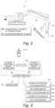
Fig. 1 is a perspective view illustrating a basic configuration of a construction equipment; -
Fig. 2 is a schematic diagram illustrating a state in which the arm of the work machine according to prior art invades the work surface; -
Fig. 3 is a block diagram illustrating a functional configuration of a construction equipment according to an embodiment of the present invention; -
Figs. 4 to 6 are schematic diagrams for explaining an example of an excavation work of a construction equipment according to an embodiment of the present invention; and -
Figs. 7 and8 are schematic diagrams illustrating arm driving speed graphs according to an embodiment of the present invention. - Hereinafter, the present invention will be explained with reference to the accompanying drawings. The present invention, however, may be modified in different ways, and should not be construed as limited to the embodiments set forth herein. Also, in order to clearly explain the present invention in the drawings, portions that are not related to the present invention are omitted, and like reference numerals are used to refer to like elements throughout the specification.
- Throughout the specification, it will be understood that when a portion is referred to as being "connected" to another portion, it can be "directly connected to" the other portion, or "indirectly connected to" the other portion having intervening portions present. Also, when a component "includes" an element, unless there is another opposite description thereto, it should be understood that the component does not exclude another element but may further include another element.
- The term including an ordinal number like "the first" or "the second" used throughout the specification of the present invention may be used to explain various constitutional elements or steps, but the corresponding constitutional elements or steps should not be limited by the ordinal number. The term including the ordinal number should be interpreted only for distinguishing one constitutional element or step from other constitutional elements or steps.
- Hereinafter, embodiments of the present invention will be explained in detail with reference to the drawings attached.
- Referring to
Figs. 3 to 6 , aconstruction equipment 100 having a boom shock mitigation function according to an embodiment of the present invention comprises a lower travelingbody 10, an upper rotatingbody 20 rotatably supported on the lower travelingbody 10, awork machine 30 which comprises aboom 31, anarm 32, and abucket 33 operated by their respective hydraulic cylinder, wherein the work machine is supported by the upper rotatingbody 20, acontrol valve 200 for controlling thearm cylinder 50, an electronic proportionalpressure reducing valve 300 for controlling the spool of thecontrol valve 200, an operation lever 400 for outputting an operation signal corresponding to an operation amount of a driver, aninformation providing unit 500 for collecting and/or calculating the location information, posture information of thework machine 30 and the location information of the work surface, and anelectronic control unit 600 for calculating and outputting a pilot pressure for the electronic proportionalpressure reducing valve 300. - The
control valve 200 is a member which opens and closes the flow path by a spool moving in the axial direction under pressure. That is, thecontrol valve 200 serves the role of switching the supply direction of the hydraulic oil supplied by the hydraulic pump, which is the hydraulic source, to theboom cylinder 40 and thearm cylinder 50 side. Thecontrol valve 200 is connected to the hydraulic pump through a hydraulic pipe, and induces supply of hydraulic oil from the hydraulic pump to theboom cylinder 40 and thearm cylinder 50. - An electronic proportional
pressure reducing valve 300 is an electronically operated valve, and may include a solenoid unit which generates an electromagnetic force and a valve unit which is used as a fluid flow path. - The electronic proportional
pressure reducing valve 300 generates hydraulic pressure in response to an electrical signal applied by theelectronic control unit 600, and the generated hydraulic pressure is transmitted from the electronic proportionalpressure reducing valve 300 to thecontrol valve 200. The hydraulic pressure from the electronic proportionalpressure reducing valve 300 causes the spool in thecontrol valve 200 to move axially. - More specifically, as the spool moves in the axial direction, the flow rate, which is the amount of hydraulic oil supplied to the
boom cylinder 40 and thearm cylinder 50 per unit time, is adjusted. In other words, when theelectronic control unit 600 determines that it is difficult for theboom 31 to be lifted or lowered following the movement amount of thearm 32, the electronic proportionalpressure reducing valve 300 changes the signal pressure so that the flow supplied to the spool of thecontrol valve 200 increases in accordance with the input of electric signal from theelectronic control unit 600. - The
operation lever 400 may be a hydraulic joystick or an electric joystick, and preferably may be an electric joystick which generates an electric signal in proportion to the operation amount of the driver and provides the same to theelectronic control unit 600. - The
information providing unit 500 may comprise at least one of alocation measuring unit 510, aposture measuring unit 520, a moment ofinertia measuring unit 530, acoordinate calculating unit 540, and anoutput calculating unit 550. - The
location measuring unit 510 may comprise a receiver capable of receiving a signal transmitted from a GPS satellite, and measures location information of the construction equipment from the received signal. - The
posture measuring unit 520 measures and/or calculates the location and posture of at least one of theboom 31,arm 32 andbucket 33, angle of main body of theconstruction equipment 100 and work surface angle, angular velocity of the arm, angular velocity of the boom, etc. by using a plurality of inertial measurement units (IMU), angle sensors, weight sensors, etc. Also, a value of the speed required for driving theboom 31 is calculated based on the angle value of thearm 32, the work surface angle, and the angular velocity value of the arm. - The moment of
inertia measuring unit 530 measures and/calculates the load, the moment of inertia, etc. of theboom 31, thearm 32, thebucket 33, and the attachment using a plurality of inertia measuring units (IMUs), weight sensors, etc. For the load and moment of inertia of an attachment such as a tilt rotator, the driver may directly input corresponding values through a display which provides a touch screen function. - The coordinate calculating
unit 540 calculates the x, y, z coordinates of at least one of the upper travelingbody 20,boom 31,arm 32,bucket 33 and tilt rotator by using the location information measured from thelocation measuring unit 510 and theposture measuring unit 520. - The
output calculating unit 550 provides the maximum output value corresponding to each engine mode to theelectronic control unit 600 when the driver operates the engine mode switch provided in the operating room and sets to any one engine mode of a power mode, a standard mode, economy mode. Of course, the engine mode may include other modes. - When an operation signal of the
operation lever 400 is input, theelectronic control unit 600 receives information from theinformation providing unit 500 and determines whether theboom 31 is to be lifted or lowered in accordance with the movement amount of thearm 32. Then, theelectronic control unit 600 outputs a current signal for controlling thecontrol valve 200 to the electronic proportionalpressure reducing valve 300. - A method for controlling the arm of the
electronic control unit 600 in consideration of the speed required for driving the boom according to an embodiment of the present invention will be explained in detail as follows. - First, when the driver operates the
boom 31 or thearm 32 through anoperation lever 400, theinformation providing unit 500 collects and/or calculates the location information, and posture information of the work machine, and the location information of the work surface, and provides the same to theelectronic control unit 600. - Specifically, the
posture measuring unit 520 calculates the current angle value of thearm 32 and the work surface angle according to the location of theboom 31,arm 32, andbucket 33 using the location information and posture information, calculates the speed required for driving theboom 31 using the angle value of thearm 32, the work surface angle, and angular velocity value of the arm, and provides the same to theelectronic control unit 600. - Then, the
electronic control unit 600 compares the calculated speed required for driving theboom 31 with a reference value. - When the speed required for driving the
boom 31 is less than or equal to a reference value, theelectronic control unit 600 classifies thearm 32 into a high-speed section in which thearm 32 drives fast according to a predetermined arm speed increase rate, and when the speed required for driving theboom 31 exceeds a reference value, theelectronic control unit 600 classifies thearm 32 into a low-speed section in which thearm 32 drives slowly according to an arm speed increase rate smaller than the predetermined arm speed increase rate. - For example, referring to
Fig. 4 , when performing work while moving the tip of thebucket 33 along a work surface including an inclined surface, as illustrated inFig. 4(a) , if thearm 32 rotates in a state in which the angle 8a with respect to the work surface is relatively close to horizontal, theboom 31 needs to be lifted a lot so that thearm 32 does not invade the work plane. At this time, the speed required for driving theboom 31 is greater than the reference value. - In this case, it is unreasonable to control the lifting of the
boom 31 following the movement amount of thearm 32. Accordingly, theelectronic control unit 600 classifies thearm 32 into a low-speed section in which thearm 32 drives slowly according to an arm speed increase rate smaller than the predetermined arm speed increase rate. - On the other hand, as illustrated in
Fig. 4(b) , if thearm 32 rotates in a state in which the angle θb with respect to the work surface is relatively close to vertical in the same work surface as inFig. 4(a) , even when theboom 31 is lifted less, thearm 32 does not invade the work surface. At this time, the speed required for driving theboom 31 is smaller than the reference value. - In this case, there is no difficulty in controlling the lifting of the
boom 31 following the movement amount of thearm 32. Accordingly, theelectronic control unit 600 classifies thearm 32 into a high-speed section in which thearm 32 drives fast according to a predetermined arm speed increase rate. - In addition, referring to
Fig. 5 , when the posture of thework machine 30 is the same, in the case of (b) where the inclination of the work surface is steep, it is unreasonable to control the lifting of theboom 31 following the movement amount of thearm 32 as compared to the case of (a) where the inclination of the work surface is relatively gradual. - In other words, in
Fig. 5(a) , the speed required for driving theboom 31 may be calculated to be smaller than the reference value, and inFig. 5(b) , the speed required for driving theboom 31 may be calculated to be greater than the reference value. -
Fig. 7(a) illustrates a graph of the speed of thearm 32 according to the operation time of theoperation lever 400 according to an embodiment of the present invention. Specifically, theelectronic control unit 600 sets a predetermined first set value as an arm speed increase rate in a high-speed section in which the speed required for driving theboom 31 is less than or equal to a reference value. - In this case, the electronic proportional
pressure reducing valve 300 generates hydraulic pressure corresponding to the pilot pressure input from theelectronic control unit 600, and when the generated hydraulic pressure is supplied to the spool of thecontrol valve 200, the spool moves axially. Accordingly, the flow rate, which is the amount of hydraulic oil supplied to thearm cylinder 50 per unit time, is adjusted to increase, and the operation speed of thearm cylinder 50 increases rapidly. - In other words, when the
electronic control unit 600 determines that the speed required for driving theboom 31 is less than or equal to a reference value and thus theboom 31 may be lifted or lowered flowing the movement amount of thearm 32, the speed of thearm 32 is allowed to increase rapidly according to the predetermined first set value. - On the other hand, in a low-speed section in which the speed required for driving the
boom 31 exceeds the reference value, since theboom 31 cannot keep up with the speed of thearm 32, the increase rate of the arm speed is controlled to be smaller than the first set value.. - In this case, the electronic proportional
pressure reducing valve 300 generates hydraulic pressure corresponding to the pilot pressure input from theelectronic control unit 600, and when the generated hydraulic pressure is supplied to the spool of thecontrol valve 200, the spool moves axially. Accordingly, the flow rate, which is the amount of hydraulic oil supplied to thearm cylinder 50 per unit time, is adjusted to decrease, and the operation speed of thearm cylinder 50 increases slowly. - In other words, when the
electronic control unit 600 determines that the speed required for driving theboom 31 exceeds a reference value and thus theboom 31 may not be lifted or lowered following the movement amount of thearm 32, the increase rate of thearm 32 is adjusted to be lower than the first set value so that theboom 31 can keep up with speed of thearm 32. - In the above, an embodiment in which the speed increase rate of the
arm 32 changes discontinuously, based on a specific reference value of the speed required for driving theboom 31, has been described. However, the speed increase rate of thearm 32 may change continuously based on the speed required for driving theboom 31. - Specifically, as illustrated in
Fig. 7(b) , when the speed required for driving theboom 31 is smaller than a first reference value, the speed of thearm 32 may be set to increase rapidly according to a value corresponding to 100% of the predetermined arm speed increase rate. In addition, as the speed required for driving theboom 31 increases, the speed increase rate of thearm 32 may be lowered gradually from the initial 100%. Also, when the speed required for driving theboom 31 is greater than a second reference value, the speed of thearm 32 may be set to increase slowly according to a value corresponding to 50% of the predetermined speed increase rate of thearm 32. - The present invention is not limited thereto, and the speed increase rate of the
arm 32 may be set to decrease gradually as the speed required for driving theboom 31 increases. - Hereinafter, a method for controlling the
arm 32 of theelectronic control unit 600 in consideration of the moment of inertia of thework machine 30 according to an embodiment of the present invention will be described in detail as follows. - When the
bucket 33 is in a loaded state or an attachment such as a tilt rotator is mounted on the tip of thearm 32, the moment of inertia for theboom 31 increases. Specifically, referring toFig. 6 , since atilt rotator 70 is mounted on the tip of thework machine 30 ofFig. 6(b) to increase the load on the tip, the moment of inertia for theboom 31 increased as compared to thework machine 30 ofFig. 6(a) . - Accordingly, in the
work machine 30 ofFig.6(b) , when thearm 32 is extended to start grading, the lifting of theboom 31 may not keep up with the speed at which thearm 32 falls due to its own weight. - Therefore, preferably, the speed increase rate of the
arm 32 is controlled by additionally considering the moment of inertia of thework machine 30. - First, when the driver operates the
boom 31 orarm 32 through theoperation lever 400, theinformation providing unit 500 collects and/or calculates the location information, posture information, and information on moment of inertia of thework machine 30, and the location information of the work surface, and provide the same to theelectronic control unit 600. Theelectronic control unit 600 compares the moment of inertia of theboom 31,arm 32 andbucket 33 provided by theinformation providing unit 500 with a reference value. -
Fig. 8(a) illustrates a graph of the speed of thearm 32 according to the operation time of theoperation lever 400 according to an embodiment of the present invention. When the moment of inertia of thework machine 30 is less than or equal to a reference value, theelectronic control unit 600 classifies thearm 32 into a high-speed section in which thearm 32 drives fast according to the predetermined arm speed increase rate, and when the moment of inertia of thework machine 30 exceeds a reference value, theelectronic control unit 600 classifies thearm 32 into a low-speed section in which thearm 32 drives slowly according to an arm speed increase rate smaller than the predetermined arm speed increase rate. - Specifically, when the
electronic control unit 600 classifies into the high-speed section, the electronic proportionalpressure reducing valve 300 generates a hydraulic pressure corresponding to the pilot pressure input from theelectronic control unit 600, and when the generated hydraulic pressure is supplied to the spool of thecontrol valve 200, the spool moves axially. Accordingly, the flow rate, which is the amount of hydraulic oil supplied to thearm cylinder 50 per unit time, is adjusted to increase, and the operation speed of thearm cylinder 50 increases rapidly. - In other words, when the
electronic control unit 600 determines that the moment of inertia for theboom 31 is small and thus theboom 31 may be lifted or lowered following the movement amount of thearm 32, the speed of thearm 32 is allowed to increase rapidly according to a predetermined second set value. - On the other hand, when the
electronic control unit 600 classifies into the low speed section, the electronic proportionalpressure reducing valve 300 generates a hydraulic pressure corresponding to the pilot pressure input from theelectronic control unit 600, and when the generated hydraulic pressure is supplied to the spool of thecontrol valve 200, the spool moves axially. Accordingly, the flow rate, which is the amount of hydraulic oil supplied to thearm cylinder 50 per unit time, is adjusted to decrease, and the operation speed of thearm cylinder 50 increases slowly. - In other words, when the
electronic control unit 600 determines that the moment of inertia for theboom 31 is large and theboom 31 may not be lifted or lowered following the movement amount of thearm 32, the speed increase rate of thearm 32 may be lowered to be lower than the second set value so that theboom 31 can keep up with the speed of thearm 32. - Hereinafter, a method for controlling the
arm 32 of theelectronic control unit 600 in consideration of the output of thework machine 30 according to an embodiment of the present invention will be described in detail. - When the driver performs work selecting standard mode or economy mode for the purpose of improving fuel efficiency, etc., the flow rate, which is the amount of hydraulic oil supplied to the hydraulic cylinder per unit time, is supplied less, and when instantaneous maximum output is required, the
boom 4a may not be lifted or lowered following the movement amount of thearm 32. - Therefore, preferably, it is preferable for the
electronic control unit 600 to control the speed increase rate of thearm 32 by additionally considering the input rotation number of thework machine 30. - First, when the driver operates the engine mode switch provided in the operating room to set the mode, and operates the
boom 31 or thearm 32 through theoperation lever 400, theinformation providing unit 500 collects and/or calculates the location information, and posture information of thework machine 30, engine maximum output value of the selected mode and the location information of the work surface, and provides the same to theelectronic control unit 600. Theelectronic control unit 600 compares the engine maximum output value of the selected mode with a predetermined reference value. -
Fig. 8(b) illustrates a graph of the speed of thearm 32 according to the operation time of theoperation lever 400 according to an embodiment of the present invention. When the engine maximum output value is greater than or equal to a reference value, theelectronic control unit 600 classifies thearm 32 into a high-speed section in which thearm 32 is driven fast according to a predetermined arm driving speed increase rate, and when the engine maximum output value is less than a reference value, theelectronic control unit 600 classifies thearm 32 into a slow-speed section in which thearm 32 is driven slowly according to an arm speed increase rate smaller than the predetermined arm driving speed increase rate. - The
electronic control unit 600 controls the speed increase rate of thearm 32 differently for the low-speed section and the high-speed section as classified above. - Specifically, when the
electronic control unit 600 classifies into the high-speed section, the electronic proportionalpressure reducing valve 300 generates a hydraulic pressure corresponding to the pilot pressure input from theelectronic control unit 600, and when the generated hydraulic pressure is supplied to the spool of thecontrol valve 200, the spool moves axially. Accordingly, the flow rate, which is the amount of hydraulic oil supplied to thearm cylinder 50 per unit time, is adjusted to increase, and the operation speed of thearm cylinder 50 increases rapidly. - In other words, when the
electronic control unit 600 determines that the engine maximum output value is large and thus theboom 31 may be lifted or lowered following the movement amount of thearm 32, the speed of thearm 32 is allowed to increase rapidly according to a predetermined third set value. - On the other hand, when the
electronic control unit 600 classifies into the low-speed section, the electronic proportionalpressure reducing valve 300 generates a hydraulic pressure corresponding to the pilot pressure input from theelectronic control unit 600, and when the generated hydraulic pressure is supplied to the spool of to thecontrol valve 200, the spool moves axially. Accordingly, the flow rate, which is the amount of hydraulic oil supplied to thearm cylinder 50 per unit time, is adjusted to decrease, and the operation speed of thearm cylinder 50 increases slowly. - In other words, when the
electronic control unit 600 determines that engine maximum output value is low and theboom 31 may not be lifted or lowered following the the movement amount of thearm 32, the speed increase rate of thearm 32 is set to be lower than the third set value so that theboom 31 may keep up with the speed of thearm 32. - Hereinafter, a method for controlling the
arm 32 of theelectronic control unit 600 in consideration of the speed required for driving theboom 31, the moment of inertia of thework machine 30, and the output of thework machine 30 according to an embodiment of the present invention will be described in detail as follows. - First, when the driver operates the engine mode switch provided in the operating room to set the mode, and operates the
boom 31 or thearm 32 through theoperation lever 400, theinformation providing unit 500 collects and/or calculates the location information, and posture information of thework machine 30, moment of inertia, engine maximum output value of the selected mode and the location information of the work surface, and provides the same to theelectronic control unit 600. - The
electronic control unit 600 compares the speed required for driving theboom 31 for the provided work surface, the moment of inertia of thework machine 30 and the engine maximum output value with a reference value, respectively, and classifies into high-speed section and low-speed section. - Next, the
electronic control unit 600 compares and determines the arm speed increase rate according to the speed required for driving theboom 31, the moment of inertia of thework machine 30 and the engine maximum output value. - Specifically, when the speed required for driving the
boom 31 is less than or equal to a reference value, theelectronic control unit 600 sets a predetermined first set value as the first arm speed increase rate, and when the speed required for driving theboom 31 exceeds a reference value, theelectronic control unit 600 sets a value obtained by multiplying the first set value by the first decrease rate as the first arm speed increase rate. - In addition, when the moment of inertia of the
work machine 30 is less than or equal to a reference value, theelectronic control unit 600 sets a predetermined second set value as the second arm speed increase rate, and when the moment of inertia of thework device 30 exceeds a reference value, theelectronic control unit 600 sets a value obtained by multiplying the second set value by the second decrease rate as the second arm speed increase rate. - In addition, when the engine output is greater than or equal to a reference value, the
electronic control unit 600 sets a predetermined third set value as the third arm speed increase rate, and when the engine output is less than a reference value, theelectronic control unit 600 sets a value obtained by multiplying the third set value by the third decrease rate as the third arm speed increase rate. - The
electronic control unit 600 sets a smallest value among the first arm speed increase rate to the third arm speed increase rate as the arm speed increase rate, and outputs a pilot pressure corresponding thereto, so as to control the flow rate, which is the amount of hydraulic oil supplied to thearm cylinder 50 per unit time, and control the operation speed of thearm cylinder 50. - As such, when a smallest arm speed increase rate is adopted in consideration of all of the speed required for driving the
boom 31, the moment of inertia of thework machine 30, and the engine maximum output value, since theboom 31 may be lifted or lowered in accordance with the movement of thearm 32 in various situations, the reliability of thearm 32 speed control may be improved. - However, the present invention is not limited thereto, and the
electronic control unit 600 may set a value obtained by multiplying any one of of the first set value to the third set value by the first decrease rate to the third decrease rate as the arm speed increase rate. In this case, since all of the first decrease rate to the third decrease rate are considered in the arm speed increase rate, the reliability of thearm 32 speed control may be further improved. - Hereinafter, a method for controlling the
boom 31 of theelectronic control unit 600 in consideration of the speed required for driving theboom 31, the moment of inertia of thework machine 30 and the output of thework machine 30 according to another embodiment of the present invention is explained in detail as follows. - First, when the driver operates the engine mode switch provided in the operating room to set the mode, and operates the
boom 31 or thearm 32 through theoperation lever 400, theinformation providing unit 500 collects and/or calculates the location information, and posture information of thework machine 30, moment of inertia, engine maximum output value of the selected mode and the location information of the work surface, and provides the same to theelectronic control unit 600. - The
electronic control unit 600 compares the provided speed required for driving theboom 31 for the provided work surface, the moment of inertia of thework machine 30 and the engine maximum output value with a reference value, respectively, and classifies into high-speed section and low-speed section. - Then, the
electronic control unit 600 compares and determines boom speed increase rate according to the speed required for driving theboom 31, the moment of inertia of thework machine 30 and the engine maximum output value. - Specifically, when the speed required for driving the
boom 31 is less than or equal to a reference value, theelectronic control unit 600 sets a predetermined first set value as the first boom speed increase rate, and when the speed required for driving theboom 31 exceeds a reference value, theelectronic control unit 600 sets a value larger than the first set value as the first boom speed increase rate. - In addition, when the moment of inertia of the
work machine 30 is less than or equal to a reference value, theelectronic control unit 600 sets a predetermined second set value as the second boom speed increase rate, and when the moment of inertia of thework machine 30 exceeds a reference value, theelectronic control unit 600 sets a value greater than the second set value is set as the second boom speed increase rate. - In addition, when the engine output is greater than or equal to a reference value, the
electronic control unit 600 sets a predetermined third set value as the third boom speed increase rate, and when the engine output is less than a reference value, theelectronic control unit 600 sets a value greater than the third set value as the third boom speed increase rate. - Next, the
electronic control unit 600 compares and determines the first boom speed increase rate to the third boom speed increase rate according to the speed required for driving theboom 31, the moment of inertia of thework machine 30, and the engine maximum output value, so as to adjust the flow rate, which is the amount of hydraulic oil supplied to theboom cylinder 40 per unit time, and adjust the operation speed of theboom cylinder 40 by calculating and outputting the pilot input according to the largest boom speed increase rate. - As such, when a largest boom speed increase rate is adopted in consideration of all of the speed required for driving the
boom 31, the moment of inertia of thework machine 30 and the engine maximum output value, since theboom 31 may be lifted or lowered in accordance with the movement amount of thearm 32 in various situations, the reliability of theboom 31 speed control may be improved. - The foregoing description of the present invention has been presented for illustrative purposes, and it is apparent to a person having ordinary skill in the art that the present invention can be easily modified into other detailed forms without changing the technical idea or essential features of the present invention. Therefore, it should be understood that the forgoing embodiments are by way of example only, and are not intended to limit the present disclosure. For example, each component which has been described as a unitary part can be implemented as distributed parts. Likewise, each component which has been described as distributed parts can also be implemented as a combined part.
- The scope of the present invention is presented by the accompanying claims, and it should be understood that all changes or modifications derived from the definitions and scopes of the claims and their equivalents fall within the scope of the present invention.
-
- 100: construction equipment
- 200: control valve
- 300: electronic proportional pressure reducing valve
- 400: operation lever
- 500: information providing unit
- 600: electronic control unit
Claims (15)
- A construction equipment, comprising:a lower traveling body;an upper rotating body rotatably supported on the lower traveling body;a work machine which comprises a boom, an arm, and a bucket operated by their respective hydraulic cylinder, wherein the work machine is supported by the upper rotating body;a control valve for controlling the hydraulic cylinder;an electronic proportional pressure reducing valve for controlling the spool of the control valve;an operation lever for outputting an operation signal corresponding to an operation amount of a driver;an information providing unit for providing information on the work machine and the work surface; andan electronic control unit for calculating and outputting a pilot pressure for the electronic proportional pressure reducing valve,wherein the electronic control unit controls the speed of the hydraulic cylinder by using the operation signal of the operation lever and the information provided by the information providing unit.
- The construction equipment of claim 1, wherein the information providing unit provides at least one of the speed required for driving the boom, the moment of inertia of the work machine, and the engine maximum output to the electronic control unit.
- The construction equipment of claim 2, wherein the electronic control unit compares the speed required for driving the boom with a reference value.
- The construction equipment of claim 3, wherein the electronic control unit sets a predetermined set value as the arm speed increase rate when the speed required for driving the boom is less than or equal to a reference value, and the electronic control unit sets a value smaller than the set value as the arm speed increase rate when the speed required for driving the boom exceeds a reference value.
- The construction equipment of claim 2, wherein the electronic control unit sets the arm speed increase rate to decrease as the speed required for driving the boom increases.
- The construction equipment of claim 2, wherein the electronic control unit compares the moment of inertia of the work machine with a reference value.
- The construction equipment of claim 6, wherein the electronic control unit sets a predetermined set value as the arm speed increase rate when the moment of inertia of the work machine is less than or equal to a reference value, and the electronic control unit sets a value smaller than the set value as the arm speed increase rate when the moment of inertia of the work machine exceeds a reference value.
- The construction equipment of claim 2, wherein the electronic control unit compares the engine maximum output with a reference value.
- The construction equipment of claim 8, wherein the electronic control unit sets a predetermined set value as the arm speed increase rate when the engine maximum output is greater than or equal to a reference value, and the electronic control unit sets a value smaller than the set value as the arm speed increase rate when the engine maximum output is less than a reference value.
- The construction equipment of claim 1,wherein the information providing unit provides the speed required for driving the boom, the moment of inertia of the work machine, and the engine maximum output to the electronic control unit,the electronic control unit compares the speed required for driving the boom, the moment of inertia of the work machine, and the engine maximum output with a reference value,the electronic control unit sets a predetermined first set value as the first arm speed increase rate when the speed required for driving the boom is less than or equal to a reference value, and the electronic control units sets a value obtained by multiplying the first set value by the first decrease rate as the first arm speed increase rate when the speed required for driving the boom exceeds a reference value,the electronic control unit sets a predetermined second set value as the second arm speed increase rate when the moment of inertia of the work machine is less than or equal to a reference value, and the electronic control unit sets a value obtained by multiplying the second set value by the second decrease rate as the second arm speed increase rate when the moment of inertia of the work machine exceeds a reference value, andthe electronic control unit sets a predetermined third set value as the third arm speed increase rate when the engine maximum output is greater than or equal to a reference value, and the electronic control unit sets a value obtained by multiplying the third set value by the third decrease rate as the third arm speed increase rate when the engine maximum output is less than a reference value.
- The construction equipment of claim 10, wherein the electronic control unit sets a smallest value among the first arm speed increase rate to the third arm speed increase rate as the arm speed increase rate.
- The construction equipment of claim 10, wherein the electronic control unit sets a value obtained by multiplying any one of the first set value to the third set value by the first decrease rate to the third decrease rate as the arm speed increase rate.
- The construction equipment of claim 1,wherein the information providing unit provides the speed required for driving the boom, the moment of inertia of the work machine, and the engine maximum output to the electronic control unit,the electronic control unit compares the speed required for driving the boom, the moment of inertia of the work machine, and the engine maximum output with a reference value,the electronic control unit sets a predetermined first set value as the first boom speed increase rate when the speed required for driving the boom is less than or equal to a reference value, and the electronic control units sets a value greater than the first set value as the first boom speed increase rate when the speed required for driving the boom exceeds a reference value,the electronic control unit sets a predetermined second set value as the second boom speed increase rate when the moment of inertia of the work machine is less than or equal to a reference value, and the electronic control unit sets a value greater than the second set value as the second boom speed increase rate when the moment of inertia of the work machine exceeds a reference value, andthe electronic control unit sets a predetermined third set value as the third boom speed increase rate when the engine maximum output is greater than or equal to a reference value, and the electronic control unit sets a value greater than the third set value as the third boom speed increase rate when the engine maximum output is less than a reference value.
- The construction equipment of claim 13, wherein the electronic control unit sets a largest value among the first boom speed increase rate to the third boom speed increase rate as the boom speed increase rate.
- The construction equipment of claim 1, wherein the operation lever generates an electric signal in proportion to the operation amount of the driver as an electric joystick to provide the same to the electronic control unit.
Applications Claiming Priority (1)
| Application Number | Priority Date | Filing Date | Title |
|---|---|---|---|
| KR1020210146645A KR20230061909A (en) | 2021-10-29 | 2021-10-29 | Construction equipment |
Publications (2)
| Publication Number | Publication Date |
|---|---|
| EP4174232A1 true EP4174232A1 (en) | 2023-05-03 |
| EP4174232B1 EP4174232B1 (en) | 2026-01-28 |
Family
ID=84044231
Family Applications (1)
| Application Number | Title | Priority Date | Filing Date |
|---|---|---|---|
| EP22203874.7A Active EP4174232B1 (en) | 2021-10-29 | 2022-10-26 | Construction equipment |
Country Status (5)
| Country | Link |
|---|---|
| US (1) | US12703957B2 (en) |
| EP (1) | EP4174232B1 (en) |
| JP (1) | JP2023067772A (en) |
| KR (1) | KR20230061909A (en) |
| CN (1) | CN116065648A (en) |
Families Citing this family (1)
| Publication number | Priority date | Publication date | Assignee | Title |
|---|---|---|---|---|
| JPWO2025075180A1 (en) * | 2023-10-06 | 2025-04-10 |
Citations (4)
| Publication number | Priority date | Publication date | Assignee | Title |
|---|---|---|---|---|
| US20160069044A1 (en) * | 2014-09-10 | 2016-03-10 | Komatsu Ltd. | Work vehicle and method of controlling work vehicle |
| US20190078290A1 (en) * | 2017-07-14 | 2019-03-14 | Komatsu Ltd. | Work machine and control method for work machine |
| US20200232186A1 (en) * | 2018-03-22 | 2020-07-23 | Hitachi Construction Machinery Co., Ltd. | Work machine |
| US20210262191A1 (en) * | 2018-11-14 | 2021-08-26 | Sumitomo Heavy Industries, Ltd. | Shovel and controller for shovel |
Family Cites Families (3)
| Publication number | Priority date | Publication date | Assignee | Title |
|---|---|---|---|---|
| JP5550064B2 (en) * | 2009-07-01 | 2014-07-16 | 住友重機械工業株式会社 | Hybrid work machine |
| KR101769485B1 (en) * | 2010-07-30 | 2017-08-30 | 볼보 컨스트럭션 이큅먼트 에이비 | Swirl flow control system for construction equipment and method of controlling the same |
| EP3951072B1 (en) * | 2019-04-05 | 2026-04-01 | Volvo Construction Equipment AB | Construction equipment |
-
2021
- 2021-10-29 KR KR1020210146645A patent/KR20230061909A/en active Pending
-
2022
- 2022-10-04 JP JP2022159939A patent/JP2023067772A/en active Pending
- 2022-10-20 CN CN202211285252.4A patent/CN116065648A/en active Pending
- 2022-10-24 US US17/971,738 patent/US12703957B2/en active Active
- 2022-10-26 EP EP22203874.7A patent/EP4174232B1/en active Active
Patent Citations (4)
| Publication number | Priority date | Publication date | Assignee | Title |
|---|---|---|---|---|
| US20160069044A1 (en) * | 2014-09-10 | 2016-03-10 | Komatsu Ltd. | Work vehicle and method of controlling work vehicle |
| US20190078290A1 (en) * | 2017-07-14 | 2019-03-14 | Komatsu Ltd. | Work machine and control method for work machine |
| US20200232186A1 (en) * | 2018-03-22 | 2020-07-23 | Hitachi Construction Machinery Co., Ltd. | Work machine |
| US20210262191A1 (en) * | 2018-11-14 | 2021-08-26 | Sumitomo Heavy Industries, Ltd. | Shovel and controller for shovel |
Also Published As
| Publication number | Publication date |
|---|---|
| US20230137581A1 (en) | 2023-05-04 |
| JP2023067772A (en) | 2023-05-16 |
| KR20230061909A (en) | 2023-05-09 |
| CN116065648A (en) | 2023-05-05 |
| EP4174232B1 (en) | 2026-01-28 |
| US12703957B2 (en) | 2026-08-11 |
Similar Documents
| Publication | Publication Date | Title |
|---|---|---|
| US10968597B2 (en) | Shovel and control method thereof | |
| CN114080481B (en) | Construction machines and support devices that support operations based on construction machines | |
| JP6581136B2 (en) | Work machine | |
| CN111655938B (en) | Excavator | |
| CN111201351A (en) | Excavator | |
| EP3951072B1 (en) | Construction equipment | |
| EP3203087A1 (en) | Work vehicle hydraulic drive system | |
| CN111511993A (en) | Excavator | |
| EP4148189A1 (en) | Construction equipment | |
| CN109511267A (en) | The control method of Work machine and Work machine | |
| EP2955279A1 (en) | Construction equipment | |
| EP4174232B1 (en) | Construction equipment | |
| JP2019173504A (en) | Hydraulic type work machine | |
| US20250277355A1 (en) | Construction equipment | |
| KR102506386B1 (en) | Control method for construction machinery | |
| JPH05295753A (en) | Construction machine automatic control method | |
| WO2025084135A1 (en) | Hydraulic control device, construction machine, and control method for construction machine | |
| WO2022230417A1 (en) | Work machine | |
| JP2026004735A (en) | Control device for work machine |
Legal Events
| Date | Code | Title | Description |
|---|---|---|---|
| PUAI | Public reference made under article 153(3) epc to a published international application that has entered the european phase |
Free format text: ORIGINAL CODE: 0009012 |
|
| STAA | Information on the status of an ep patent application or granted ep patent |
Free format text: STATUS: THE APPLICATION HAS BEEN PUBLISHED |
|
| AK | Designated contracting states |
Kind code of ref document: A1 Designated state(s): AL AT BE BG CH CY CZ DE DK EE ES FI FR GB GR HR HU IE IS IT LI LT LU LV MC ME MK MT NL NO PL PT RO RS SE SI SK SM TR |
|
| STAA | Information on the status of an ep patent application or granted ep patent |
Free format text: STATUS: REQUEST FOR EXAMINATION WAS MADE |
|
| 17P | Request for examination filed |
Effective date: 20231102 |
|
| RBV | Designated contracting states (corrected) |
Designated state(s): AL AT BE BG CH CY CZ DE DK EE ES FI FR GB GR HR HU IE IS IT LI LT LU LV MC ME MK MT NL NO PL PT RO RS SE SI SK SM TR |
|
| GRAP | Despatch of communication of intention to grant a patent |
Free format text: ORIGINAL CODE: EPIDOSNIGR1 |
|
| STAA | Information on the status of an ep patent application or granted ep patent |
Free format text: STATUS: GRANT OF PATENT IS INTENDED |
|
| RIC1 | Information provided on ipc code assigned before grant |
Ipc: E02F 3/43 20060101AFI20250730BHEP Ipc: E02F 9/22 20060101ALI20250730BHEP Ipc: F15B 21/08 20060101ALI20250730BHEP |
|
| INTG | Intention to grant announced |
Effective date: 20250828 |
|
| GRAS | Grant fee paid |
Free format text: ORIGINAL CODE: EPIDOSNIGR3 |
|
| GRAA | (expected) grant |
Free format text: ORIGINAL CODE: 0009210 |
|
| STAA | Information on the status of an ep patent application or granted ep patent |
Free format text: STATUS: THE PATENT HAS BEEN GRANTED |
|
| AK | Designated contracting states |
Kind code of ref document: B1 Designated state(s): AL AT BE BG CH CY CZ DE DK EE ES FI FR GB GR HR HU IE IS IT LI LT LU LV MC ME MK MT NL NO PL PT RO RS SE SI SK SM TR |
|
| REG | Reference to a national code |
Ref country code: CH Ref legal event code: F10 Free format text: ST27 STATUS EVENT CODE: U-0-0-F10-F00 (AS PROVIDED BY THE NATIONAL OFFICE) Effective date: 20260128 Ref country code: GB Ref legal event code: FG4D |
|
| REG | Reference to a national code |
Ref country code: DE Ref legal event code: R096 Ref document number: 602022029191 Country of ref document: DE |
|
| REG | Reference to a national code |
Ref country code: IE Ref legal event code: FG4D |
|
| REG | Reference to a national code |
Ref country code: NL Ref legal event code: MP Effective date: 20260128 |
|
| PG25 | Lapsed in a contracting state [announced via postgrant information from national office to epo] |
Ref country code: NL Free format text: LAPSE BECAUSE OF FAILURE TO SUBMIT A TRANSLATION OF THE DESCRIPTION OR TO PAY THE FEE WITHIN THE PRESCRIBED TIME-LIMIT Effective date: 20260128 |
|
| REG | Reference to a national code |
Ref country code: AT Ref legal event code: MK05 Ref document number: 1881382 Country of ref document: AT Kind code of ref document: T Effective date: 20260128 |
|
| PG25 | Lapsed in a contracting state [announced via postgrant information from national office to epo] |
Ref country code: RS Free format text: LAPSE BECAUSE OF FAILURE TO SUBMIT A TRANSLATION OF THE DESCRIPTION OR TO PAY THE FEE WITHIN THE PRESCRIBED TIME-LIMIT Effective date: 20260428 |
|
| PG25 | Lapsed in a contracting state [announced via postgrant information from national office to epo] |
Ref country code: ES Free format text: LAPSE BECAUSE OF FAILURE TO SUBMIT A TRANSLATION OF THE DESCRIPTION OR TO PAY THE FEE WITHIN THE PRESCRIBED TIME-LIMIT Effective date: 20260128 |
|
| PG25 | Lapsed in a contracting state [announced via postgrant information from national office to epo] |
Ref country code: PL Free format text: LAPSE BECAUSE OF FAILURE TO SUBMIT A TRANSLATION OF THE DESCRIPTION OR TO PAY THE FEE WITHIN THE PRESCRIBED TIME-LIMIT Effective date: 20260128 |
|
| PG25 | Lapsed in a contracting state [announced via postgrant information from national office to epo] |
Ref country code: GR Free format text: LAPSE BECAUSE OF FAILURE TO SUBMIT A TRANSLATION OF THE DESCRIPTION OR TO PAY THE FEE WITHIN THE PRESCRIBED TIME-LIMIT Effective date: 20260429 |
|
| REG | Reference to a national code |
Ref country code: LT Ref legal event code: MG9D |
|
| PG25 | Lapsed in a contracting state [announced via postgrant information from national office to epo] |
Ref country code: LT Free format text: LAPSE BECAUSE OF FAILURE TO SUBMIT A TRANSLATION OF THE DESCRIPTION OR TO PAY THE FEE WITHIN THE PRESCRIBED TIME-LIMIT Effective date: 20260128 |
|
| PG25 | Lapsed in a contracting state [announced via postgrant information from national office to epo] |
Ref country code: NO Free format text: LAPSE BECAUSE OF FAILURE TO SUBMIT A TRANSLATION OF THE DESCRIPTION OR TO PAY THE FEE WITHIN THE PRESCRIBED TIME-LIMIT Effective date: 20260428 |
|
| PG25 | Lapsed in a contracting state [announced via postgrant information from national office to epo] |
Ref country code: FI Free format text: LAPSE BECAUSE OF FAILURE TO SUBMIT A TRANSLATION OF THE DESCRIPTION OR TO PAY THE FEE WITHIN THE PRESCRIBED TIME-LIMIT Effective date: 20260128 Ref country code: SE Free format text: LAPSE BECAUSE OF FAILURE TO SUBMIT A TRANSLATION OF THE DESCRIPTION OR TO PAY THE FEE WITHIN THE PRESCRIBED TIME-LIMIT Effective date: 20260128 Ref country code: AT Free format text: LAPSE BECAUSE OF FAILURE TO SUBMIT A TRANSLATION OF THE DESCRIPTION OR TO PAY THE FEE WITHIN THE PRESCRIBED TIME-LIMIT Effective date: 20260128 |
|
| PG25 | Lapsed in a contracting state [announced via postgrant information from national office to epo] |
Ref country code: HR Free format text: LAPSE BECAUSE OF FAILURE TO SUBMIT A TRANSLATION OF THE DESCRIPTION OR TO PAY THE FEE WITHIN THE PRESCRIBED TIME-LIMIT Effective date: 20260128 |
|
| PG25 | Lapsed in a contracting state [announced via postgrant information from national office to epo] |
Ref country code: PT Free format text: LAPSE BECAUSE OF FAILURE TO SUBMIT A TRANSLATION OF THE DESCRIPTION OR TO PAY THE FEE WITHIN THE PRESCRIBED TIME-LIMIT Effective date: 20260528 Ref country code: IS Free format text: LAPSE BECAUSE OF FAILURE TO SUBMIT A TRANSLATION OF THE DESCRIPTION OR TO PAY THE FEE WITHIN THE PRESCRIBED TIME-LIMIT Effective date: 20260528 |
|
| PG25 | Lapsed in a contracting state [announced via postgrant information from national office to epo] |
Ref country code: LV Free format text: LAPSE BECAUSE OF FAILURE TO SUBMIT A TRANSLATION OF THE DESCRIPTION OR TO PAY THE FEE WITHIN THE PRESCRIBED TIME-LIMIT Effective date: 20260128 |
|
| PG25 | Lapsed in a contracting state [announced via postgrant information from national office to epo] |
Ref country code: BG Free format text: LAPSE BECAUSE OF FAILURE TO SUBMIT A TRANSLATION OF THE DESCRIPTION OR TO PAY THE FEE WITHIN THE PRESCRIBED TIME-LIMIT Effective date: 20260128 |