EP4174023A1 - Positive electrode active material for lithium-ion battery, production method therefor, and lithium-ion battery - Google Patents
Positive electrode active material for lithium-ion battery, production method therefor, and lithium-ion battery Download PDFInfo
- Publication number
- EP4174023A1 EP4174023A1 EP22204770.6A EP22204770A EP4174023A1 EP 4174023 A1 EP4174023 A1 EP 4174023A1 EP 22204770 A EP22204770 A EP 22204770A EP 4174023 A1 EP4174023 A1 EP 4174023A1
- Authority
- EP
- European Patent Office
- Prior art keywords
- positive electrode
- electrode active
- active material
- lithium
- ion battery
- Prior art date
- Legal status (The legal status is an assumption and is not a legal conclusion. Google has not performed a legal analysis and makes no representation as to the accuracy of the status listed.)
- Pending
Links
Images

Classifications
-
- H—ELECTRICITY
- H01—ELECTRIC ELEMENTS
- H01M—PROCESSES OR MEANS, e.g. BATTERIES, FOR THE DIRECT CONVERSION OF CHEMICAL ENERGY INTO ELECTRICAL ENERGY
- H01M4/00—Electrodes
- H01M4/02—Electrodes composed of, or comprising, active material
- H01M4/36—Selection of substances as active materials, active masses, active liquids
-
- C—CHEMISTRY; METALLURGY
- C01—INORGANIC CHEMISTRY
- C01G—COMPOUNDS CONTAINING METALS NOT COVERED BY SUBCLASSES C01D OR C01F
- C01G31/00—Compounds of vanadium
- C01G31/006—Compounds containing vanadium, with or without oxygen or hydrogen, and containing two or more other elements
-
- H—ELECTRICITY
- H01—ELECTRIC ELEMENTS
- H01M—PROCESSES OR MEANS, e.g. BATTERIES, FOR THE DIRECT CONVERSION OF CHEMICAL ENERGY INTO ELECTRICAL ENERGY
- H01M4/00—Electrodes
- H01M4/02—Electrodes composed of, or comprising, active material
- H01M4/36—Selection of substances as active materials, active masses, active liquids
- H01M4/48—Selection of substances as active materials, active masses, active liquids of inorganic oxides or hydroxides
- H01M4/485—Selection of substances as active materials, active masses, active liquids of inorganic oxides or hydroxides of mixed oxides or hydroxides for inserting or intercalating light metals, e.g. LiTi2O4 or LiTi2OxFy
-
- H—ELECTRICITY
- H01—ELECTRIC ELEMENTS
- H01M—PROCESSES OR MEANS, e.g. BATTERIES, FOR THE DIRECT CONVERSION OF CHEMICAL ENERGY INTO ELECTRICAL ENERGY
- H01M10/00—Secondary cells; Manufacture thereof
- H01M10/05—Accumulators with non-aqueous electrolyte
- H01M10/052—Li-accumulators
- H01M10/0525—Rocking-chair batteries, i.e. batteries with lithium insertion or intercalation in both electrodes; Lithium-ion batteries
-
- H—ELECTRICITY
- H01—ELECTRIC ELEMENTS
- H01M—PROCESSES OR MEANS, e.g. BATTERIES, FOR THE DIRECT CONVERSION OF CHEMICAL ENERGY INTO ELECTRICAL ENERGY
- H01M4/00—Electrodes
- H01M4/02—Electrodes composed of, or comprising, active material
- H01M4/13—Electrodes for accumulators with non-aqueous electrolyte, e.g. for lithium-accumulators; Processes of manufacture thereof
- H01M4/131—Electrodes based on mixed oxides or hydroxides, or on mixtures of oxides or hydroxides, e.g. LiCoOx
-
- C—CHEMISTRY; METALLURGY
- C01—INORGANIC CHEMISTRY
- C01P—INDEXING SCHEME RELATING TO STRUCTURAL AND PHYSICAL ASPECTS OF SOLID INORGANIC COMPOUNDS
- C01P2002/00—Crystal-structural characteristics
- C01P2002/70—Crystal-structural characteristics defined by measured X-ray, neutron or electron diffraction data
- C01P2002/72—Crystal-structural characteristics defined by measured X-ray, neutron or electron diffraction data by d-values or two theta-values, e.g. as X-ray diagram
-
- C—CHEMISTRY; METALLURGY
- C01—INORGANIC CHEMISTRY
- C01P—INDEXING SCHEME RELATING TO STRUCTURAL AND PHYSICAL ASPECTS OF SOLID INORGANIC COMPOUNDS
- C01P2002/00—Crystal-structural characteristics
- C01P2002/70—Crystal-structural characteristics defined by measured X-ray, neutron or electron diffraction data
- C01P2002/76—Crystal-structural characteristics defined by measured X-ray, neutron or electron diffraction data by a space-group or by other symmetry indications
-
- C—CHEMISTRY; METALLURGY
- C01—INORGANIC CHEMISTRY
- C01P—INDEXING SCHEME RELATING TO STRUCTURAL AND PHYSICAL ASPECTS OF SOLID INORGANIC COMPOUNDS
- C01P2006/00—Physical properties of inorganic compounds
- C01P2006/40—Electric properties
-
- H—ELECTRICITY
- H01—ELECTRIC ELEMENTS
- H01M—PROCESSES OR MEANS, e.g. BATTERIES, FOR THE DIRECT CONVERSION OF CHEMICAL ENERGY INTO ELECTRICAL ENERGY
- H01M4/00—Electrodes
- H01M4/02—Electrodes composed of, or comprising, active material
- H01M2004/026—Electrodes composed of, or comprising, active material characterised by the polarity
- H01M2004/028—Positive electrodes
-
- Y—GENERAL TAGGING OF NEW TECHNOLOGICAL DEVELOPMENTS; GENERAL TAGGING OF CROSS-SECTIONAL TECHNOLOGIES SPANNING OVER SEVERAL SECTIONS OF THE IPC; TECHNICAL SUBJECTS COVERED BY FORMER USPC CROSS-REFERENCE ART COLLECTIONS [XRACs] AND DIGESTS
- Y02—TECHNOLOGIES OR APPLICATIONS FOR MITIGATION OR ADAPTATION AGAINST CLIMATE CHANGE
- Y02E—REDUCTION OF GREENHOUSE GAS [GHG] EMISSIONS, RELATED TO ENERGY GENERATION, TRANSMISSION OR DISTRIBUTION
- Y02E60/00—Enabling technologies; Technologies with a potential or indirect contribution to GHG emissions mitigation
- Y02E60/10—Energy storage using batteries
Definitions
- the present disclosure relates to a positive electrode active material for a lithium-ion battery, a production method therefor, and a lithium-ion battery.
- Patent Literature 1 discloses a positive electrode active material for a lithium-ion battery having a layered rock salt structure belonging to space group R-3m, and having a composition represented by Li 1+x Ti y V z D a O 2 (where D is a doping element, 0 ⁇ x ⁇ 1, 0 ⁇ y ⁇ 0.5, 0.3 ⁇ z ⁇ 1, and 0 ⁇ a ⁇ 0.2). Furthermore, Non-Patent Literature 1 discloses an electrode active material having a layered rock salt structure and having a composition represented by (1-x)LiVO 2 ⁇ xLi 2 TiO 3 (where 0 ⁇ x ⁇ 0.6).
- positive electrode active materials having a rock salt structure have significant volume changes during charging and discharging. When applied to a lithium-ion battery, this can be a factor in deteriorating the cycle characteristics of the battery.
- the present disclosure provides:
- the present disclosure provides: a lithium-ion battery comprising the positive electrode active material of the present disclosure.
- the positive electrode active material for a lithium-ion battery of the present disclosure can be produced by, for example, the following method. Specifically, the production method of the present disclosure may comprise the steps of:
- the positive electrode active material of the present disclosure has small volume changes during charging and discharging. By applying such a positive electrode active material to a lithium-ion battery, the cycle characteristics of the battery can easily be improved.
- the positive electrode active material for a lithium-ion battery of the present disclosure has a disordered rock salt structure belonging to space group Fm-3m, and has a composition represented by Li 1+x Ti y V z O 2 (where 0 ⁇ x ⁇ 0.20, 0 ⁇ y ⁇ 0.40, and 0.40 ⁇ z ⁇ 0.85).
- the positive electrode active material of the present disclosure has a disordered rock salt structure belonging to space group Fm-3m. According to such a positive electrode active material, volume changes are easily suppressed due to the movement of V. For example, a volume change, if any, is likely to be isotropic expansion and contraction, and a one-dimensional volume change is unlikely to occur. In the positive electrode active material of the present disclosure, change in the lattice constant of the crystal structure during charging and discharging is suppressed to, for example, 1% or less. Thus, by applying the positive electrode active material, which has small volume change due to charging and discharging, to a lithium-ion battery, the cycle characteristics of the battery can easily be improved.
- the positive electrode active material of the present disclosure has the composition represented by Li 1+x Ti y V z O 2 .
- the relationships 0 ⁇ x ⁇ 0.20, 0 ⁇ y ⁇ 0.40, and 0.40 ⁇ z ⁇ 0.85 are satisfied.
- the disordered rock salt structure described above is easily maintained, and the effects described above are easily exhibited.
- high charge-discharge capacity can easily be obtained.
- x is greater than 0, and may be 0.01 or more, 0.02 or more, 0.03 or more, 0.04 or more, 0.05 or more, 0.06 or more, 0.07 or more, 0.08 or more, 0.09 or more, 0.10 or more, or 0.11 or more. Furthermore, x is 0.20 or less, and may be 0.19 or less, 0.18 or less, 0.17 or less, 0.16 or less, 0.15 or less, or 0.14 or less.
- y is greater than 0, and may be 0.01 or more, 0.03 or more, 0.05 or more, 0.07 or more, 0.09 or more, 0.10 or more, 0.11 or more, 0.13 or more, 0.15 or more, 0.17 or more, 0.19 or more, 0.21 or more, or 0.22 or more. Furthermore, y is 0.40 or less, and may be 0.39 or less, 0.38 or less, 0.37 or less, 0.36 or less, 0.35 or less, 0.34 or less, 0.33 or less, 0.32 or less, 0.31 or less, 0.30 or less, or 0.29 or less.
- z is 0.40 or more, and may be 0.42 or more, 0.44 or more, 0.46 or more, 0.48 or more, 0.50 or more, 0.52 or more, 0.54 or more, 0.56 or more, or 0.57 or more. Furthermore, z is 0.85 or less, and may be 0.83 or less, 0.81 or less, 0.79 or less, 0.77 or less, 0.75 or less, 0.73 or less, 0.71 or less, 0.69 or less, or 0.67 or less.
- the positive electrode active material of the present disclosure is only required to have the crystal structure and composition described above and is not particularly limited by the other constituent features.
- an appropriate shape such as particulate or thin film may be selected in accordance with the shape of the battery.
- the particles may be solid particles or hollow particles.
- the particles of the positive electrode active material may be primary particles or secondary particles in which a plurality of primary particles are aggregated.
- the average particle diameter (D50) of the particles of the positive electrode active material may be, for example, 1 nm or more, 5 nm or more, or 10 nm or more, and may be 500 ⁇ m or less, 100 ⁇ m or less, 50 ⁇ m or less, or 30 ⁇ m or less.
- the average particle diameter D50 referred to herein is the particle diameter (median diameter) at the integrated value of 50% in a volume-based particle size distribution determined by the laser diffraction/scattering method.
- a protective layer containing a Li-ion conductive oxide may be formed on the surface of the positive electrode active material of the present disclosure.
- Li-ion conductive oxide examples include Li 3 BO 3 , LiBO 2 , Li 2 CO 3 , LiAlO 2 , Li 4 SiO 4 , Li 2 SiO 3 , Li 3 PO 4 , Li 2 SO 4 , Li 2 TiO 3 , Li 4 Ti 5 O 12 , Li 2 Ti 2 O 5 , Li 2 ZrO 3 , LiNbO 3 , Li 2 MoO 4 , and Li 2 WO 4 .
- An element of the Li-ion conductive oxide may be partially substituted with a doping element such as P or B.
- the coverage (area ratio) of the protective layer may be, for example, 70% or more, 80% or more, or 90% or more.
- the thickness of the protective layer may be, for example, 0.1 nm or more, or 1 nm or more, and may be 100 nm or less, or 20 nm or less.
- the positive electrode active material of the present disclosure can be produced by, for example, the following method. As shown in FIG. 1 , the production method according to an embodiment may comprise:
- step S1 an intermediate substance having a layered rock salt structure (belonging to space group R-3m) and having a composition represented by Li 1+x Ti y V z O 2 (where 0 ⁇ x ⁇ 0.20, 0 ⁇ y ⁇ 0.40, and 0.40 ⁇ z ⁇ 0.85) is produced.
- the intermediate substance can be produced by, for example, firing (calcining, baking, sintering) a mixture of a Li source, a Ti source, and a V source, after optionally molding the mixture.
- Examples of the Li source constituting the mixture include Li 2 CO 3 .
- Examples of the Ti source include TiO 2 .
- examples of the V source include V 2 O 3 .
- the desired layered rock salt structure is easily formed in the intermediate substance, and the desired disordered rock salt structure is easily formed in the ultimate positive electrode active material.
- raw materials other than the those described above may be used as the raw materials constituting the mixture, and further, a compound (such as a composite oxide) which serves as at least two of the Li source, the Ti source, and the V source may be used.
- the composition ratio of Li, Ti, and V contained in the mixture can be appropriately determined in accordance with the composition ratio of the ultimate positive electrode active material.
- the mixture may be adjusted so that Li is included in excess. As a result, even if Li is volatilized during the firing in step S1, or if Li is consumed by a side reaction in step S2, which will be described later, the Li shortfall can be compensated for. That is, the desired composition is easily obtained in the ultimate positive electrode active material.
- the method for mixing the Li source, the Ti source, and the V source is not particularly limited.
- the Li source, the Ti source, and the V source can be uniformly mixed by wet mechanical milling using a solvent.
- a solvent for example, an organic solvent such as ethanol may be used as the solvent.
- the wet mechanical milling can be performed by mechanical mixing means such as, for example, a planetary ball mill.
- the mixing conditions (mixing time, rotation speed, number of repetitions, etc.) of the wet mechanical milling are not particularly limited, and the conditions may be such that the Li source, the Ti source, and the V source are uniformly mixed to the extent that the desired layered rock salt structure can be formed after firing, which is described later.
- the mixture described above may be molded into pellets prior to firing.
- the sizes and shapes of the molded bodies are not particularly limited.
- the firing atmosphere is not particularly limited, and may be, for example, an oxygen-containing atmosphere such as the ambient atmosphere or an air atmosphere, or an inert gas atmosphere such as an Ar atmosphere. Particularly when it is an inert gas atmosphere, the desired intermediate substance can easily be obtained.
- the firing temperature is not particularly limited as long as a layered rock salt structure can be obtained. For example, it may be 800 °C or higher, or 850 °C or higher, and may be 1000 °C or lower, or 950 °C or lower.
- the firing time is not particularly limited either, and may be, for example, 5 hours or more, 7 hours or more, 10 hours or more, or 12 hours or more, and may be 100 hours or less, 50 hours or less, or 20 hours or less.
- step S2 by subjecting the intermediate substance described above to dry mechanical milling, a positive electrode active material having a disordered rock salt structure belonging to space group Fm-3m, and having a composition represented by Li 1+x Ti y V z O 2 (where 0 ⁇ x ⁇ 0.20, 0 ⁇ y ⁇ 0.40, and 0.40 ⁇ z ⁇ 0.85) is obtained.
- a positive electrode active material having a disordered rock salt structure belonging to space group Fm-3m and having a composition represented by Li 1+x Ti y V z O 2 (where 0 ⁇ x ⁇ 0.20, 0 ⁇ y ⁇ 0.40, and 0.40 ⁇ z ⁇ 0.85) is obtained.
- dry mechanical milling can be performed by mechanical mixing means such as, for example, a planetary ball mill.
- the dry mechanical milling conditions are not particularly limited.
- the rotation speed may be 500 to 700 rpm
- the rotation time may be 10 to 20 minutes
- the rest time may be 1 to 5 minutes.
- the rotation and the rest may be repeated multiple times. Further, a set of rotation and rest may be repeated multiple times.
- the crystallite size of the positive electrode active material can be controlled.
- the composition ratio of Li, Ti, and V may vary or may be substantially the same without variation.
- the intermediate substance having a layered rock salt structure is produced by a solid phase reaction method in the explanation above, the intermediate substance production method is not limited thereto.
- the intermediate substance having a layered rock salt structure is subjected to dry mechanical milling in the above explanation, there is room for the adoption of other methods for obtaining the positive electrode active material having a disordered rock salt structure.
- the present inventors have confirmed, after producing an intermediate substance having a layered rock salt structure, by subjecting the intermediate substance to dry mechanical milling, the target disordered rock salt structure can be obtained more stably and easily.
- the technology of the present disclosure also has an aspect as a positive electrode for a lithium-ion battery.
- the positive electrode of the present disclosure comprises the positive electrode active material described above.
- the positive electrode 10 according to an embodiment may comprise a positive electrode active material layer 11 and a positive electrode current collector 12, and in this case, the positive electrode active material layer 11 may comprise the positive electrode active material described above.
- the positive electrode active material layer 11 comprises at least the positive electrode active material described above, and may optionally comprise an electrolyte, a conductive agent, and a binder.
- the content of each of the positive electrode active material, the electrolyte, the conductive agent, and the binder in the positive electrode active material layer 11 may be appropriately determined in accordance with the target battery performance. For example, when the entire positive electrode active material layer 11 (total solid content) is 100% by mass, the content of the positive electrode active material may be 40% by mass or more, 50% by mass or more, or 60% by mass or more, and may be 100% by mass or less, or 90% by mass or less.
- the shape of the positive electrode active material layer 11 is not particularly limited, and may be, for example, a sheet-like positive electrode active material layer 11 having a substantially flat surface.
- the thickness of the positive electrode active material layer 11 is not particularly limited, and may be, for example, 0.1 ⁇ m or more, or 1 ⁇ m or more, and may be 2 mm or less, or 1 mm or less.
- the positive electrode active material layer 11 may comprise only the positive electrode active material having a disordered rock salt structure described above as the positive electrode active material.
- the positive electrode active material layer 11 may comprises a different type of positive electrode active material (another positive electrode active material) in addition to the positive electrode active material described above. From the viewpoint of further enhancing the effect of the technology of the present disclosure, the content of other positive electrode active material in the positive electrode active material layer 11 may be small.
- the positive electrode active material having a disordered rock salt structure described above may occupy 50% by mass or more, 60% by mass or more, 70% by mass or more, 80% by mass or more, 90% by mass or more, 95% by mass or more, or 99% by mass or more of the total positive electrode active material contained in the positive electrode active material layer 11.
- the electrolyte may be a solid electrolyte, or may be a liquid electrolyte (electrolytic solution).
- the positive electrode active material layer 11 may comprise a solid electrolyte as the electrolyte.
- the positive electrode active material layer 11 may contain an electrolytic solution as an electrolyte, or the positive electrode active material layer 11 is in contact with an electrolytic solution.
- the positive electrode 10 is a positive electrode for a liquid electrolyte battery, it is sufficient that the positive electrode active material layer 11 and the electrolytic solution be in contact at least after the battery is constructed. The same is true for the negative electrode 30, which will be described later.
- the solid electrolyte may be any known solid electrolyte for batteries.
- the solid electrolyte may be an inorganic solid electrolyte or an organic polymer electrolyte.
- inorganic solid electrolytes have higher ionic conductivity than organic polymer electrolytes.
- inorganic solid electrolytes have excellent heat resistance as compared with organic polymer electrolytes.
- oxide solid electrolytes such as lithium lanthanum zirconate, LiPON, Li 1+X Al X Ge 2-X (PO 4 ) 3 , Li-SiO-based glasses, and Li-Al-S-O-based glasses
- sulfide solid electrolytes such as Li 2 S-P 2 S 5 , Li 2 S-SiS 2 , LiI-Li 2 S-SiS 2 , LiI-Si 2 S-P 2 S 5 , Li 2 S-P 2 S 5 -LiI-LiBr, LiI-Li 2 S-P 2 S 5 , LiI-Li 2 S-P 2 O 5 , LiI-Li 3 PO 4 -P 2 S 5 , and Li 2 S-P 2 S 5 -GeS 2 can be exemplified.
- sulfide solid electrolytes and thereamong, sulfide solid electrolytes containing Li 2 S-P 2 S 5 , have high performance.
- the solid electrolyte may be amorphous or crystalline.
- the solid electrolyte may be, for example, particulate. Only one type of solid electrolyte may be used alone, or two or more types may be used in combination.
- the electrolytic solution may contain, for example, lithium ions as carrier ions.
- the electrolytic solution may be an aqueous electrolytic solution or a non-aqueous electrolytic solution.
- the composition of the electrolytic solution may be the same as that of the composition of known lithium-ion battery electrolytic solutions.
- a solution obtained by dissolving a lithium salt at a predetermined concentration in a carbonate-based solvent can be used as the electrolytic solution.
- the carbonate-based solvent include fluoroethylene carbonate (FEC), ethylene carbonate (EC), and dimethyl carbonate (DMC).
- the lithium salt include LiPF 6 .
- the conductive agent examples include carbon materials such as vapor grown carbon fiber (VGCF), acetylene black (AB), Ketjen black (KB), carbon nanotubes (CNT), and carbon nanofibers (CNF); and metal materials such as nickel, aluminum, and stainless steel.
- the conductive agent may be, for example, particulate or fibrous, and the size thereof is not particularly limited. One type of conductive agent may be used alone, or two or more types may be used in combination.
- binder examples include butadiene rubber (BR) based binder, butylene rubber (IIR) based binder, acrylate butadiene rubber (ABR) based binder, styrene-butadiene rubber (SBR) based binder, polyvinylidene fluoride (PVdF) based binder, polytetrafluoroethylene (PTFE) based binder, and polyimide (PI) based binder.
- BR butadiene rubber
- IIR acrylate butadiene rubber
- SBR styrene-butadiene rubber
- PVdF polyvinylidene fluoride
- PTFE polytetrafluoroethylene
- PI polyimide
- the positive electrode 10 may comprise a positive electrode current collector 12 which is in contact with the positive electrode active material layer 11 described above.
- Any general positive electrode current collector for batteries can be used as the positive electrode current collector 12.
- the positive electrode current collector 12 may be in the form of a foil, plate, mesh, punched metal, or foam.
- the positive electrode current collector 12 may be composed of a metal foil or a metal mesh. In particular, metal foil is excellent in handleability.
- the positive electrode current collector 12 may be composed of a plurality of sheets of foil. Examples of the metal constituting the positive electrode current collector 12 include Cu, Ni, Cr, Au, Pt, Ag, Al, Fe, Ti, Zn, Co, and stainless steel.
- the positive electrode current collector 12 may contain Al.
- the positive electrode current collector 12 may have some type of coating layer on the surface thereof for the purpose of, for example, adjusting resistance.
- the positive electrode current collector 12 may be a metal foil or a base material plated or vapor-deposited with the metal described above.
- the positive electrode current collector 12 may have some type of layer between the plurality of metal foils.
- the thickness of the positive electrode current collector 12 is not particularly limited. For example, it may be 0.1 ⁇ m or more, or 1 ⁇ m or more, and may be 1 mm or less, or 100 ⁇ m or less.
- the positive electrode 10 may have any of constituents which are conventional for positive electrodes for batteries. Examples thereof include tabs and terminals.
- the positive electrode 10 can be produced by a known method except that the positive electrode active material having the disordered rock salt structure described above is used.
- the positive electrode active material layer 11 can be easily molded by dry or wet molding of a positive electrode mixture containing the various components described above.
- the positive electrode active material layer 11 may be molded together with the positive electrode current collector 12 or may be molded separately from the positive electrode current collector 12.
- the technology of the present disclosure also includes an aspect as a lithium-ion battery.
- the lithium-ion battery of the present disclosure comprises the positive electrode active material of the present disclosure.
- the positive electrode active material of the present disclosure has small volume changes during charging and discharging, and thus, when applied to a lithium-ion battery, the cycle characteristics of the battery can easily be improved.
- the constituents of the lithium-ion battery of the present disclosure are not particularly limited as long as the positive electrode active material of the present disclosure is contained.
- a lithium-ion battery 100 may comprise a positive electrode 10, an electrolyte layer 20, and a negative electrode 30.
- the positive electrode 10 is as described above.
- the electrolyte layer 20 comprises at least an electrolyte.
- the electrolyte layer 20 comprises a solid electrolyte and optionally a binder.
- the contents of the solid electrolyte and the binder of the electrolyte layer 20 are not particularly limited.
- the electrolyte layer 20 may contain an electrolytic solution, and it may comprise a separator for containing an electrolytic solution and preventing contact between the positive electrode active material layer 11 and the negative electrode active material layer 31.
- the thickness of the electrolyte layer 20 is not particularly limited, and may be, for example, 0.1 ⁇ m or more, or 1 ⁇ m or more, and may be 2 mm or less or 1 mm or less.
- the separator may be a separator which is commonly used in lithium-ion batteries, and examples thereof include the one composed of a resin such as polyethylene (PE), polypropylene (PP), polyester, or polyamide.
- the separator may have a single-layer structure or a multi-layer structure. Examples of the separator having a multilayer structure include a separator having a two-layer PE/PP structure and a separator having a three-layer PP/PE/PP or PE/PP/PE structure.
- the separator may be composed of a nonwoven fabric such as a cellulose nonwoven fabric, a resin nonwoven fabric, or a glass fiber nonwoven fabric.
- the negative electrode 30 may comprise a negative electrode active material layer 31 and a negative electrode current collector 32.
- the negative electrode active material layer 31 contains at least a negative electrode active material, and may optionally contain an electrolyte, a conductive agent, and a binder.
- the content of each of the negative electrode active material, the electrolyte, the conductive agent, and the binder in the negative electrode active material layer 31 may be appropriately determined according to the desired battery performance. For example, when the entire negative electrode active material layer 31 (total solid content) is 100% by mass, the content of the negative electrode active material may be 40% by mass or more, 50% by mass or more, or 60% by mass or more, and may be 100% by mass or less or 90% by mass or less.
- the shape of the negative electrode active material layer 31 is not particularly limited, and may be, for example, a sheet-like negative electrode active material layer having a substantially flat surface.
- the thickness of the negative electrode active material layer 31 is not particularly limited, and may be, for example, 0.1 ⁇ m or more, or 1 ⁇ m or more, and may be 2 mm or less or 1 mm or less.
- отри ⁇ ное отно ⁇ ество отное отное ⁇ лектро ⁇ ное ⁇ лектро ⁇ ное ⁇ лектро ⁇ ное ⁇ лектро ⁇ ное ⁇ лектро ⁇ ное ⁇ лектро ⁇ ное ⁇ лектро ⁇ ное ⁇ лект ⁇ ⁇ лект ⁇ ⁇ лект ⁇ ⁇ лект ⁇ ⁇ лек, ⁇ еловлекл ⁇ ел ⁇ ел ⁇ ел ⁇ ел ⁇ ел ⁇ ел ⁇ ел ⁇ ел ⁇ ел ⁇ ел ⁇ ел ⁇ ел ⁇ ел ⁇ ел ⁇ ел ⁇ ел ⁇ ел ⁇ ел ⁇ ел ⁇ ел ⁇ ел ⁇ ел ⁇ ел ⁇ ел ⁇ ел ⁇ ел ⁇ ел ⁇ ел ⁇ ел ⁇ ел ⁇ ел ⁇ ел ⁇ ел ⁇ ел ⁇ ел ⁇ ел ⁇ ел ⁇ ел ⁇ ел ⁇ ел ⁇ ел ⁇ ел ⁇ ел ⁇ ел ⁇ е
- the shape of the negative electrode active material may be a conventional shape as a negative electrode active material for batteries.
- the negative electrode active material may be particulate.
- the negative electrode active material particles may be primary particles or secondary particles in which a plurality of primary particles are aggregated.
- the average particle diameter (D50) of the negative electrode active material particles may be, for example, 1 nm or more, 5 nm or more, or 10 nm or more, and may be 500 ⁇ m or less, 100 ⁇ m or less, 50 ⁇ m or less, or 30 ⁇ m or less.
- the negative electrode active material may be in the form of a sheet (foil, film) such as metallic lithium foil. That is, the negative electrode active material layer 31 may be composed of a negative electrode active material sheet.
- Examples of the electrolyte which can be included in the negative electrode active material layer 31 include the solid electrolytes and electrolytic solutions described above.
- Examples of the conductive agent which can be included in the negative electrode active material layer 31 include the carbon materials and the metal materials described above.
- the binder which can be included in the negative electrode active material layer 31 may be appropriately selected from, for example, those exemplified as binders which can be included in the positive electrode active material layer 11 described above.
- the negative electrode 30 may comprise a negative electrode current collector 32 which is in contact with the negative electrode active material layer 31 described above.
- Any conventional negative electrode current collector for batteries can be used as the negative electrode current collector 32.
- the negative electrode current collector 32 may be in the form of a foil, plate, mesh, punched metal, or foam.
- the negative electrode current collector 32 may be a metal foil or a metal mesh, or may be a carbon sheet. In particular, metal foil is excellent in handleability.
- the negative electrode current collector 32 may be composed of a plurality of foils or sheets. Examples of the metal constituting the negative electrode current collector 32 include Cu, Ni, Cr, Au, Pt, Ag, Al, Fe, Ti, Zn, Co, and stainless steel.
- the negative electrode current collector 32 may comprise at least one metal selected from Cu, Ni, and stainless steel from the viewpoint of ensuring reduction resistance and preventing alloying with lithium.
- the negative electrode current collector 32 may have some type of coating layer on the surface thereof for the purpose of, for example, adjusting resistance.
- the negative electrode current collector 32 may be a metal foil or a base material plated or vapor-deposited with the metal described above. When the negative electrode current collector 32 is composed of a plurality of metal foils, it may have some type of layer between the plurality of metal foils.
- the thickness of the negative electrode current collector 32 is not particularly limited. For example, it may be 0.1 ⁇ m or more, or 1 ⁇ m or more, and may be 1 mm or less, or 100 ⁇ m or less.
- the negative electrode 30 may have any constituents which are conventional as a negative electrode for batteries. Examples thereof include tabs and terminals.
- the lithium-ion battery 100 may comprise each of the constituents described above housed inside an exterior body.
- the exterior body any known exterior body for batteries can be used.
- a plurality of batteries 100 may be electrically connected and stacked to form an assembled battery.
- the assembled battery may be housed inside a known battery case.
- the lithium-ion battery 100 may also have obvious constituents such as necessary terminals. Examples of the shape of the lithium-ion battery 100 include a coin shape, a laminate shape, a cylindrical shape, and a rectangular shape.
- the lithium-ion battery 100 can be produced by adopting a known method.
- the method for producing the lithium-ion battery 100 includes laminating the positive electrode 10, the electrolyte layer 20, and the negative electrode 30 described above.
- a specific example of the method for producing the lithium-ion battery 100 is shown below.
- the method for producing the lithium-ion battery 100 is not limited to the method described below, and each layer may be formed by, for example, dry molding.
- the positive electrode active material having a disordered rock salt structure was synthesized by the following method.
- Li 2 CO 3 (excess of 3%), TiO 2 , and V 2 O 3 as raw materials were each weighed so as to achieve a predetermined ratio, and mixed by wet ball milling (wet BM), which is one type of wet mechanical milling.
- the wet BM conditions are as shown in Table 1 below. Thereafter, the mixture was pelletized.
- the molded pellets were placed on a boat-shaped aluminum board, wrapped with Cu foil, and fired at 900 °C for 12 hours in an Ar atmosphere to obtain the intermediate substance.
- the values of x, y, and z were variously changed, and a plurality of types of intermediate substances were obtained.
- Positive electrode active materials were obtained by subjecting the respective intermediate substances to dry ball milling (dry BM), which is one type of dry mechanical milling.
- dry BM dry ball milling
- the dry BM conditions are as shown in Table 1 below. It was confirmed that the positive electrode active materials had a disordered rock salt structure belonging to space group Fm-3m, and had a composition represented by Li 1+x Ti y V z O 2 (where 0 ⁇ x ⁇ 0.20, 0 ⁇ y ⁇ 0.40, and 0.40 ⁇ z ⁇ 0.85).
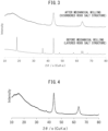
- FIG. 3 shows an example of X-ray diffraction peaks of an intermediate substance before dry mechanical milling and an example of X-ray diffraction peaks of a positive electrode active material after dry mechanical milling.
- LiVO 2 as a positive electrode active material which does not contain Ti was prepared. Furthermore, Li 2 TiO 3 as a positive electrode active material which does not contain V was prepared. The specific methods for synthesizing LiVO 2 and Li 2 TiO 3 conform to the method for synthesizing the Li-Ti-VO-based positive electrode active materials according to Examples 1 to 6 described above.
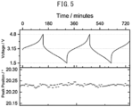
- Table 2 shows the maximum volume change rate along the c-axis during charging and discharging for Example 1 and Comparative Examples 1 to 3. Further, FIG. 5 shows an example of the shift change of the X-ray diffraction peaks due to charging and discharging of a positive electrode active material according to an Example.
- Composition Maximum volume change rate (C-axis) Ex 1 Li 8/7 Ti 2/7 V 4/7 O 2 0.46% Comp Ex1 LiNi 1/3 Co 1/3 Mn 1/3 O 2 2.0% Comp Ex2 LiNi 0.85 Co 0.10 Al 0.05 O 2 2.5% Comp Ex3 LiNi 0.5 Mn 0.5 O 2 1.4%
- the positive electrode active material described above, acetylene black as a conductive agent, and PVDF as a binder were weighed at a mass ratio of 76.5:13.5:10.0, mixed and dispersed in N-methylpyrrolidone to obtain a positive electrode mixture slurry.
- a positive electrode was obtained by applying the positive electrode mixture slurry onto an Al current collector foil and vacuum-drying at 120 °C overnight.
- a coin cell (CR2032) was produced using the positive electrode, a non-aqueous electrolytic solution (electrolyte: 1 M LiPF 6 , solvent: ethylene carbonate (EC) and dimethyl carbonate (DMC) mixed at 30:70 vol%), and a metallic lithium foil as a negative electrode.
- the positive electrode active materials represented by LiVO 2 and Li 2 TiO 3 could ensure sufficient discharge capacity when applied to the positive electrode of a lithium-ion battery.
- positive electrode active materials which satisfy the following requirements (1) and (2) have small volume changes during charging and discharging, and can improve the cycle characteristics of a lithium-ion battery when used, for example, in a wide SOC range with a reversible capacity of 250 mAh/g or more. Furthermore, a positive electrode having a sufficient discharge capacity can be obtained.
Landscapes
- Chemical & Material Sciences (AREA)
- Chemical Kinetics & Catalysis (AREA)
- Electrochemistry (AREA)
- General Chemical & Material Sciences (AREA)
- Engineering & Computer Science (AREA)
- Inorganic Chemistry (AREA)
- Materials Engineering (AREA)
- Organic Chemistry (AREA)
- Manufacturing & Machinery (AREA)
- Battery Electrode And Active Subsutance (AREA)
Abstract
Description
- The present disclosure relates to a positive electrode active material for a lithium-ion battery, a production method therefor, and a lithium-ion battery.
- Patent Literature 1 discloses a positive electrode active material for a lithium-ion battery having a layered rock salt structure belonging to space group R-3m, and having a composition represented by Li1+xTiyVzDaO2 (where D is a doping element, 0 ≤ x < 1, 0 < y < 0.5, 0.3 ≤ z < 1, and 0 ≤ a ≤ 0.2). Furthermore, Non-Patent Literature 1 discloses an electrode active material having a layered rock salt structure and having a composition represented by (1-x)LiVO2·xLi2TiO3 (where 0 ≤ x ≤ 0.6).
- [PTL 1]
JP 2019-091580 A - [NPL 1] Journal of Power Sources, 174, 2007, pp. 1007-1011
- According to the findings of the present inventors, positive electrode active materials having a rock salt structure have significant volume changes during charging and discharging. When applied to a lithium-ion battery, this can be a factor in deteriorating the cycle characteristics of the battery.
- As one means for solving the problem described above, the present disclosure provides:
- a positive electrode active material for a lithium-ion battery,
- having a disordered rock salt structure belonging to space group Fm-3m, and
- having a composition represented by Li1+xTiyVzO2 (where 0 < x ≤ 0.20, 0 < y ≤ 0.40, and 0.40 ≤ z ≤ 0.85).
- As one means for solving the problem described above, the present disclosure provides:
a lithium-ion battery comprising the positive electrode active material of the present disclosure. - The positive electrode active material for a lithium-ion battery of the present disclosure can be produced by, for example, the following method. Specifically, the production method of the present disclosure may comprise the steps of:
- producing an intermediate substance having a layered rock salt structure and having a composition represented by Li1+xTiyVzO2 (where 0 < x ≤ 0.20, 0 < y ≤ 0.40, and 0.40 ≤ z ≤ 0.85), and
- subjecting the intermediate substance to dry mechanical milling to obtain a positive electrode active material having a disordered rock salt structure belonging to space group Fm-3m, and having a composition represented by Li1+xTiyVzO2 (where 0 < x ≤ 0.20, 0 < y ≤ 0.40, and 0.40 ≤ z ≤ 0.85).
- The positive electrode active material of the present disclosure has small volume changes during charging and discharging. By applying such a positive electrode active material to a lithium-ion battery, the cycle characteristics of the battery can easily be improved.
-
-
FIG. 1 shows an example of a method for producing a positive electrode active material for a lithium-ion battery. -
FIG. 2 schematically shows an example of the structure of a positive electrode and a lithium-ion battery. -
FIG. 3 is a comparison of the X-ray diffraction peaks of an intermediate substance before dry mechanical milling and a positive electrode active material after dry mechanical milling. -
FIG. 4 shows powder X-ray diffraction peaks of a positive electrode active material according to an Example. -
FIG. 5 shows the shift change of X-ray diffraction peaks due to charging and discharging of a positive electrode active material according to an Example. - The positive electrode active material for a lithium-ion battery of the present disclosure has a disordered rock salt structure belonging to space group Fm-3m, and has a composition represented by Li1+xTiyVzO2 (where 0 < x ≤ 0.20, 0 < y ≤ 0.40, and 0.40 ≤ z ≤ 0.85).
- Regarding conventionally known positive electrode active materials having a layered rock salt structure, reversible transition metal migration during charging and discharging processes is difficult, and the volume tends to expand or contract greatly in one dimension along with the insertion or desorption of Li. Conversely, the positive electrode active material of the present disclosure has a disordered rock salt structure belonging to space group Fm-3m. According to such a positive electrode active material, volume changes are easily suppressed due to the movement of V. For example, a volume change, if any, is likely to be isotropic expansion and contraction, and a one-dimensional volume change is unlikely to occur. In the positive electrode active material of the present disclosure, change in the lattice constant of the crystal structure during charging and discharging is suppressed to, for example, 1% or less. Thus, by applying the positive electrode active material, which has small volume change due to charging and discharging, to a lithium-ion battery, the cycle characteristics of the battery can easily be improved.
- The positive electrode active material of the present disclosure has the composition represented by Li1+xTiyVzO2. Here, the relationships 0 < x ≤ 0.20, 0 < y ≤ 0.40, and 0.40 ≤ z ≤ 0.85 are satisfied. When such a composition is provided, the disordered rock salt structure described above is easily maintained, and the effects described above are easily exhibited. Furthermore, when such a composition is provided, high charge-discharge capacity can easily be obtained.
- x is greater than 0, and may be 0.01 or more, 0.02 or more, 0.03 or more, 0.04 or more, 0.05 or more, 0.06 or more, 0.07 or more, 0.08 or more, 0.09 or more, 0.10 or more, or 0.11 or more. Furthermore, x is 0.20 or less, and may be 0.19 or less, 0.18 or less, 0.17 or less, 0.16 or less, 0.15 or less, or 0.14 or less.
- y is greater than 0, and may be 0.01 or more, 0.03 or more, 0.05 or more, 0.07 or more, 0.09 or more, 0.10 or more, 0.11 or more, 0.13 or more, 0.15 or more, 0.17 or more, 0.19 or more, 0.21 or more, or 0.22 or more. Furthermore, y is 0.40 or less, and may be 0.39 or less, 0.38 or less, 0.37 or less, 0.36 or less, 0.35 or less, 0.34 or less, 0.33 or less, 0.32 or less, 0.31 or less, 0.30 or less, or 0.29 or less.
- z is 0.40 or more, and may be 0.42 or more, 0.44 or more, 0.46 or more, 0.48 or more, 0.50 or more, 0.52 or more, 0.54 or more, 0.56 or more, or 0.57 or more. Furthermore, z is 0.85 or less, and may be 0.83 or less, 0.81 or less, 0.79 or less, 0.77 or less, 0.75 or less, 0.73 or less, 0.71 or less, 0.69 or less, or 0.67 or less.
- The positive electrode active material of the present disclosure is only required to have the crystal structure and composition described above and is not particularly limited by the other constituent features.
- Regarding the shape of the positive electrode active material, an appropriate shape such as particulate or thin film may be selected in accordance with the shape of the battery. When the positive electrode active material is particulate, the particles may be solid particles or hollow particles. The particles of the positive electrode active material may be primary particles or secondary particles in which a plurality of primary particles are aggregated. The average particle diameter (D50) of the particles of the positive electrode active material may be, for example, 1 nm or more, 5 nm or more, or 10 nm or more, and may be 500 µm or less, 100 µm or less, 50 µm or less, or 30 µm or less. The average particle diameter D50 referred to herein is the particle diameter (median diameter) at the integrated value of 50% in a volume-based particle size distribution determined by the laser diffraction/scattering method.
- A protective layer containing a Li-ion conductive oxide may be formed on the surface of the positive electrode active material of the present disclosure. As a result, reactions between the positive electrode active material and a sulfide (for example, a sulfide solid electrolyte, which is described later) can easily be suppressed. Examples of the Li-ion conductive oxide include Li3BO3, LiBO2, Li2CO3, LiAlO2, Li4SiO4, Li2SiO3, Li3PO4, Li2SO4, Li2TiO3, Li4Ti5O12, Li2Ti2O5, Li2ZrO3, LiNbO3, Li2MoO4, and Li2WO4. An element of the Li-ion conductive oxide may be partially substituted with a doping element such as P or B. The coverage (area ratio) of the protective layer may be, for example, 70% or more, 80% or more, or 90% or more. The thickness of the protective layer may be, for example, 0.1 nm or more, or 1 nm or more, and may be 100 nm or less, or 20 nm or less.
- The positive electrode active material of the present disclosure can be produced by, for example, the following method. As shown in
FIG. 1 , the production method according to an embodiment may comprise: - step S1: producing an intermediate substance having a layered rock salt structure and having a composition represented by Li1+xTiyVzO2 (where 0 < x ≤ 0.20, 0 < y ≤ 0.40, and 0.40 ≤ z ≤ 0.85), and
- step S2: subjecting the intermediate substance to dry mechanical milling to obtain a positive electrode active material having a disordered rock salt structure belonging to space group Fm-3m, and having a composition represented by Li1+xTiyVzO2 (where 0 < x ≤ 0.20, 0 < y ≤ 0.40, and 0.40 ≤ z ≤ 0.85).
- In step S1, an intermediate substance having a layered rock salt structure (belonging to space group R-3m) and having a composition represented by Li1+xTiyVzO2 (where 0 < x ≤ 0.20, 0 < y ≤ 0.40, and 0.40 ≤ z ≤ 0.85) is produced. The intermediate substance can be produced by, for example, firing (calcining, baking, sintering) a mixture of a Li source, a Ti source, and a V source, after optionally molding the mixture.
- Examples of the Li source constituting the mixture include Li2CO3. Examples of the Ti source include TiO2. Further, examples of the V source include V2O3. By adopting Li2CO3, TiO2, and V2O3 as the Li source, the Ti source, and the V source, respectively, the desired layered rock salt structure is easily formed in the intermediate substance, and the desired disordered rock salt structure is easily formed in the ultimate positive electrode active material. Alternatively, raw materials other than the those described above may be used as the raw materials constituting the mixture, and further, a compound (such as a composite oxide) which serves as at least two of the Li source, the Ti source, and the V source may be used. The composition ratio of Li, Ti, and V contained in the mixture can be appropriately determined in accordance with the composition ratio of the ultimate positive electrode active material. The mixture may be adjusted so that Li is included in excess. As a result, even if Li is volatilized during the firing in step S1, or if Li is consumed by a side reaction in step S2, which will be described later, the Li shortfall can be compensated for. That is, the desired composition is easily obtained in the ultimate positive electrode active material.
- The method for mixing the Li source, the Ti source, and the V source is not particularly limited. The Li source, the Ti source, and the V source can be uniformly mixed by wet mechanical milling using a solvent. For example, an organic solvent such as ethanol may be used as the solvent. The wet mechanical milling can be performed by mechanical mixing means such as, for example, a planetary ball mill. The mixing conditions (mixing time, rotation speed, number of repetitions, etc.) of the wet mechanical milling are not particularly limited, and the conditions may be such that the Li source, the Ti source, and the V source are uniformly mixed to the extent that the desired layered rock salt structure can be formed after firing, which is described later.
- The mixture described above may be molded into pellets prior to firing. The sizes and shapes of the molded bodies are not particularly limited.
- By firing the mixture or molded bodies described above, an intermediate substance having a layered rock salt structure and the composition described above is obtained. The firing atmosphere is not particularly limited, and may be, for example, an oxygen-containing atmosphere such as the ambient atmosphere or an air atmosphere, or an inert gas atmosphere such as an Ar atmosphere. Particularly when it is an inert gas atmosphere, the desired intermediate substance can easily be obtained. The firing temperature is not particularly limited as long as a layered rock salt structure can be obtained. For example, it may be 800 °C or higher, or 850 °C or higher, and may be 1000 °C or lower, or 950 °C or lower. The firing time (retention time at the firing temperature) is not particularly limited either, and may be, for example, 5 hours or more, 7 hours or more, 10 hours or more, or 12 hours or more, and may be 100 hours or less, 50 hours or less, or 20 hours or less.
- In step S2, by subjecting the intermediate substance described above to dry mechanical milling, a positive electrode active material having a disordered rock salt structure belonging to space group Fm-3m, and having a composition represented by Li1+xTiyVzO2 (where 0 < x ≤ 0.20, 0 < y ≤ 0.40, and 0.40 ≤ z ≤ 0.85) is obtained. Specifically, by subjecting the intermediate substance described above to dry mechanical milling, in which a solvent is not substantially used, the layered rock salt structure of the intermediate substance is changed, whereby a positive electrode active material having a disordered rock salt structure is obtained. Dry mechanical milling can be performed by mechanical mixing means such as, for example, a planetary ball mill. The dry mechanical milling conditions (mixing time, rotation speed, number of repetitions, etc.) are not particularly limited. For example, when using a planetary ball mill, the rotation speed may be 500 to 700 rpm, the rotation time may be 10 to 20 minutes, and the rest time may be 1 to 5 minutes. The rotation and the rest may be repeated multiple times. Further, a set of rotation and rest may be repeated multiple times. By adjusting the dry mechanical milling conditions, for example, the crystallite size of the positive electrode active material can be controlled.
- Note that in the production method of the present disclosure from the mixture through the intermediate substance to the positive electrode active material, the composition ratio of Li, Ti, and V may vary or may be substantially the same without variation. Furthermore, though the intermediate substance having a layered rock salt structure is produced by a solid phase reaction method in the explanation above, the intermediate substance production method is not limited thereto. Furthermore, though the intermediate substance having a layered rock salt structure is subjected to dry mechanical milling in the above explanation, there is room for the adoption of other methods for obtaining the positive electrode active material having a disordered rock salt structure. However, as far as the present inventors have confirmed, after producing an intermediate substance having a layered rock salt structure, by subjecting the intermediate substance to dry mechanical milling, the target disordered rock salt structure can be obtained more stably and easily.
- The technology of the present disclosure also has an aspect as a positive electrode for a lithium-ion battery. Specifically, the positive electrode of the present disclosure comprises the positive electrode active material described above. As shown in
FIG. 2 , thepositive electrode 10 according to an embodiment may comprise a positive electrodeactive material layer 11 and a positive electrodecurrent collector 12, and in this case, the positive electrodeactive material layer 11 may comprise the positive electrode active material described above. - The positive electrode
active material layer 11 comprises at least the positive electrode active material described above, and may optionally comprise an electrolyte, a conductive agent, and a binder. The content of each of the positive electrode active material, the electrolyte, the conductive agent, and the binder in the positive electrodeactive material layer 11 may be appropriately determined in accordance with the target battery performance. For example, when the entire positive electrode active material layer 11 (total solid content) is 100% by mass, the content of the positive electrode active material may be 40% by mass or more, 50% by mass or more, or 60% by mass or more, and may be 100% by mass or less, or 90% by mass or less. The shape of the positive electrodeactive material layer 11 is not particularly limited, and may be, for example, a sheet-like positive electrodeactive material layer 11 having a substantially flat surface. The thickness of the positive electrodeactive material layer 11 is not particularly limited, and may be, for example, 0.1 µm or more, or 1 µm or more, and may be 2 mm or less, or 1 mm or less. - The positive electrode
active material layer 11 may comprise only the positive electrode active material having a disordered rock salt structure described above as the positive electrode active material. Alternatively, the positive electrodeactive material layer 11 may comprises a different type of positive electrode active material (another positive electrode active material) in addition to the positive electrode active material described above. From the viewpoint of further enhancing the effect of the technology of the present disclosure, the content of other positive electrode active material in the positive electrodeactive material layer 11 may be small. For example, the positive electrode active material having a disordered rock salt structure described above may occupy 50% by mass or more, 60% by mass or more, 70% by mass or more, 80% by mass or more, 90% by mass or more, 95% by mass or more, or 99% by mass or more of the total positive electrode active material contained in the positive electrodeactive material layer 11. - The electrolyte may be a solid electrolyte, or may be a liquid electrolyte (electrolytic solution). When the
positive electrode 10 is a positive electrode for a solid-state battery (a battery containing a solid electrolyte), the positive electrodeactive material layer 11 may comprise a solid electrolyte as the electrolyte. Furthermore, when thepositive electrode 10 is a positive electrode for a liquid electrolyte battery, the positive electrodeactive material layer 11 may contain an electrolytic solution as an electrolyte, or the positive electrodeactive material layer 11 is in contact with an electrolytic solution. When thepositive electrode 10 is a positive electrode for a liquid electrolyte battery, it is sufficient that the positive electrodeactive material layer 11 and the electrolytic solution be in contact at least after the battery is constructed. The same is true for thenegative electrode 30, which will be described later. - The solid electrolyte may be any known solid electrolyte for batteries. The solid electrolyte may be an inorganic solid electrolyte or an organic polymer electrolyte. In particular, inorganic solid electrolytes have higher ionic conductivity than organic polymer electrolytes. Furthermore, inorganic solid electrolytes have excellent heat resistance as compared with organic polymer electrolytes. As the inorganic solid electrolyte, for example, oxide solid electrolytes such as lithium lanthanum zirconate, LiPON, Li1+XAlXGe2-X(PO4)3, Li-SiO-based glasses, and Li-Al-S-O-based glasses; and sulfide solid electrolytes such as Li2S-P2S5, Li2S-SiS2, LiI-Li2S-SiS2, LiI-Si2S-P2S5, Li2S-P2S5-LiI-LiBr, LiI-Li2S-P2S5, LiI-Li2S-P2O5, LiI-Li3PO4-P2S5, and Li2S-P2S5-GeS2 can be exemplified. In particular, sulfide solid electrolytes, and thereamong, sulfide solid electrolytes containing Li2S-P2S5, have high performance. The solid electrolyte may be amorphous or crystalline. The solid electrolyte may be, for example, particulate. Only one type of solid electrolyte may be used alone, or two or more types may be used in combination.
- The electrolytic solution may contain, for example, lithium ions as carrier ions. The electrolytic solution may be an aqueous electrolytic solution or a non-aqueous electrolytic solution. The composition of the electrolytic solution may be the same as that of the composition of known lithium-ion battery electrolytic solutions. For example, as the electrolytic solution, a solution obtained by dissolving a lithium salt at a predetermined concentration in a carbonate-based solvent can be used. Examples of the carbonate-based solvent include fluoroethylene carbonate (FEC), ethylene carbonate (EC), and dimethyl carbonate (DMC). Examples of the lithium salt include LiPF6.
- Examples of the conductive agent include carbon materials such as vapor grown carbon fiber (VGCF), acetylene black (AB), Ketjen black (KB), carbon nanotubes (CNT), and carbon nanofibers (CNF); and metal materials such as nickel, aluminum, and stainless steel. The conductive agent may be, for example, particulate or fibrous, and the size thereof is not particularly limited. One type of conductive agent may be used alone, or two or more types may be used in combination.
- 3.1.4 Binder
- Examples of the binder include butadiene rubber (BR) based binder, butylene rubber (IIR) based binder, acrylate butadiene rubber (ABR) based binder, styrene-butadiene rubber (SBR) based binder, polyvinylidene fluoride (PVdF) based binder, polytetrafluoroethylene (PTFE) based binder, and polyimide (PI) based binder. Only one type of binder may be used alone, or two or more types may be used in combination.
- As shown in
FIG. 2 , thepositive electrode 10 may comprise a positive electrodecurrent collector 12 which is in contact with the positive electrodeactive material layer 11 described above. Any general positive electrode current collector for batteries can be used as the positive electrodecurrent collector 12. Furthermore, the positive electrodecurrent collector 12 may be in the form of a foil, plate, mesh, punched metal, or foam. The positive electrodecurrent collector 12 may be composed of a metal foil or a metal mesh. In particular, metal foil is excellent in handleability. The positive electrodecurrent collector 12 may be composed of a plurality of sheets of foil. Examples of the metal constituting the positive electrodecurrent collector 12 include Cu, Ni, Cr, Au, Pt, Ag, Al, Fe, Ti, Zn, Co, and stainless steel. In particular, from the viewpoint of ensuring oxidation resistance, the positive electrodecurrent collector 12 may contain Al. The positive electrodecurrent collector 12 may have some type of coating layer on the surface thereof for the purpose of, for example, adjusting resistance. Furthermore, the positive electrodecurrent collector 12 may be a metal foil or a base material plated or vapor-deposited with the metal described above. When the positive electrodecurrent collector 12 is composed of a plurality of metal foils, it may have some type of layer between the plurality of metal foils. The thickness of the positive electrodecurrent collector 12 is not particularly limited. For example, it may be 0.1 µm or more, or 1 µm or more, and may be 1 mm or less, or 100 µm or less. - In addition to the constituents described above, the
positive electrode 10 may have any of constituents which are conventional for positive electrodes for batteries. Examples thereof include tabs and terminals. Thepositive electrode 10 can be produced by a known method except that the positive electrode active material having the disordered rock salt structure described above is used. For example, the positive electrodeactive material layer 11 can be easily molded by dry or wet molding of a positive electrode mixture containing the various components described above. The positive electrodeactive material layer 11 may be molded together with the positive electrodecurrent collector 12 or may be molded separately from the positive electrodecurrent collector 12. - The technology of the present disclosure also includes an aspect as a lithium-ion battery. Specifically, the lithium-ion battery of the present disclosure comprises the positive electrode active material of the present disclosure. As described above, the positive electrode active material of the present disclosure has small volume changes during charging and discharging, and thus, when applied to a lithium-ion battery, the cycle characteristics of the battery can easily be improved. The constituents of the lithium-ion battery of the present disclosure are not particularly limited as long as the positive electrode active material of the present disclosure is contained. For example, as shown in
FIG. 2 , a lithium-ion battery 100 according to an embodiment may comprise apositive electrode 10, anelectrolyte layer 20, and anegative electrode 30. Thepositive electrode 10 is as described above. - The
electrolyte layer 20 comprises at least an electrolyte. When the lithium-ion battery 100 is a solid-state battery, theelectrolyte layer 20 comprises a solid electrolyte and optionally a binder. In this case, the contents of the solid electrolyte and the binder of theelectrolyte layer 20 are not particularly limited. On the other hand, when the lithium-ion battery 100 is a liquid electrolyte battery, theelectrolyte layer 20 may contain an electrolytic solution, and it may comprise a separator for containing an electrolytic solution and preventing contact between the positive electrodeactive material layer 11 and the negative electrodeactive material layer 31. The thickness of theelectrolyte layer 20 is not particularly limited, and may be, for example, 0.1 µm or more, or 1 µm or more, and may be 2 mm or less or 1 mm or less. - The solid electrolyte, the electrolytic solution, and the binder are as described above. The separator may be a separator which is commonly used in lithium-ion batteries, and examples thereof include the one composed of a resin such as polyethylene (PE), polypropylene (PP), polyester, or polyamide. The separator may have a single-layer structure or a multi-layer structure. Examples of the separator having a multilayer structure include a separator having a two-layer PE/PP structure and a separator having a three-layer PP/PE/PP or PE/PP/PE structure. The separator may be composed of a nonwoven fabric such as a cellulose nonwoven fabric, a resin nonwoven fabric, or a glass fiber nonwoven fabric.
- As shown in
FIG. 2 , thenegative electrode 30 may comprise a negative electrodeactive material layer 31 and a negative electrodecurrent collector 32. - The negative electrode
active material layer 31 contains at least a negative electrode active material, and may optionally contain an electrolyte, a conductive agent, and a binder. The content of each of the negative electrode active material, the electrolyte, the conductive agent, and the binder in the negative electrodeactive material layer 31 may be appropriately determined according to the desired battery performance. For example, when the entire negative electrode active material layer 31 (total solid content) is 100% by mass, the content of the negative electrode active material may be 40% by mass or more, 50% by mass or more, or 60% by mass or more, and may be 100% by mass or less or 90% by mass or less. The shape of the negative electrodeactive material layer 31 is not particularly limited, and may be, for example, a sheet-like negative electrode active material layer having a substantially flat surface. The thickness of the negative electrodeactive material layer 31 is not particularly limited, and may be, for example, 0.1 µm or more, or 1 µm or more, and may be 2 mm or less or 1 mm or less. - Various substances having a lower potential (charge/discharge potential) at which lithium ions are inserted or desorbed than the positive electrode active material described above can be used as the negative electrode active material. For example, silicon-based active materials such as Si, Si alloys, and silicon oxide; carbon-based active materials such as graphite and hard carbon; various oxide-based active materials such as lithium titanate; and metallic lithium and lithium alloys can be used. Only one type of the negative electrode active material may be used alone, or two or more types may be used in combination.
- The shape of the negative electrode active material may be a conventional shape as a negative electrode active material for batteries. For example, the negative electrode active material may be particulate. The negative electrode active material particles may be primary particles or secondary particles in which a plurality of primary particles are aggregated. The average particle diameter (D50) of the negative electrode active material particles may be, for example, 1 nm or more, 5 nm or more, or 10 nm or more, and may be 500 µm or less, 100 µm or less, 50 µm or less, or 30 µm or less. Alternatively, the negative electrode active material may be in the form of a sheet (foil, film) such as metallic lithium foil. That is, the negative electrode
active material layer 31 may be composed of a negative electrode active material sheet. - Examples of the electrolyte which can be included in the negative electrode
active material layer 31 include the solid electrolytes and electrolytic solutions described above. Examples of the conductive agent which can be included in the negative electrodeactive material layer 31 include the carbon materials and the metal materials described above. The binder which can be included in the negative electrodeactive material layer 31 may be appropriately selected from, for example, those exemplified as binders which can be included in the positive electrodeactive material layer 11 described above. - As shown in
FIG. 2 , thenegative electrode 30 may comprise a negative electrodecurrent collector 32 which is in contact with the negative electrodeactive material layer 31 described above. Any conventional negative electrode current collector for batteries can be used as the negative electrodecurrent collector 32. Furthermore, the negative electrodecurrent collector 32 may be in the form of a foil, plate, mesh, punched metal, or foam. The negative electrodecurrent collector 32 may be a metal foil or a metal mesh, or may be a carbon sheet. In particular, metal foil is excellent in handleability. The negative electrodecurrent collector 32 may be composed of a plurality of foils or sheets. Examples of the metal constituting the negative electrodecurrent collector 32 include Cu, Ni, Cr, Au, Pt, Ag, Al, Fe, Ti, Zn, Co, and stainless steel. In particular, the negative electrodecurrent collector 32 may comprise at least one metal selected from Cu, Ni, and stainless steel from the viewpoint of ensuring reduction resistance and preventing alloying with lithium. The negative electrodecurrent collector 32 may have some type of coating layer on the surface thereof for the purpose of, for example, adjusting resistance. Furthermore, the negative electrodecurrent collector 32 may be a metal foil or a base material plated or vapor-deposited with the metal described above. When the negative electrodecurrent collector 32 is composed of a plurality of metal foils, it may have some type of layer between the plurality of metal foils. The thickness of the negative electrodecurrent collector 32 is not particularly limited. For example, it may be 0.1 µm or more, or 1 µm or more, and may be 1 mm or less, or 100 µm or less. In addition to the constituents described above, thenegative electrode 30 may have any constituents which are conventional as a negative electrode for batteries. Examples thereof include tabs and terminals. - The lithium-ion battery 100 may comprise each of the constituents described above housed inside an exterior body. As the exterior body, any known exterior body for batteries can be used. A plurality of batteries 100 may be electrically connected and stacked to form an assembled battery. In this case, the assembled battery may be housed inside a known battery case. The lithium-ion battery 100 may also have obvious constituents such as necessary terminals. Examples of the shape of the lithium-ion battery 100 include a coin shape, a laminate shape, a cylindrical shape, and a rectangular shape.
- The lithium-ion battery 100 can be produced by adopting a known method. For example, the method for producing the lithium-ion battery 100 includes laminating the
positive electrode 10, theelectrolyte layer 20, and thenegative electrode 30 described above. A specific example of the method for producing the lithium-ion battery 100 is shown below. However, the method for producing the lithium-ion battery 100 is not limited to the method described below, and each layer may be formed by, for example, dry molding. - (1) The positive electrode active material constituting the positive electrode active material layer is dispersed in a solvent to obtain a slurry for the positive electrode layer. The solvent used in this case is not particularly limited, and water and various organic solvents can be used, and N-methylpyrrolidone (NMP) may be used. The slurry is applied to the surface of a positive electrode current collector using a doctor blade and then dried to form a positive electrode active material layer on the surface of the positive electrode current collector, thereby obtaining a positive electrode.
- (2) The negative electrode active material constituting the negative electrode active material layer is dispersed in a solvent to obtain a slurry for the negative electrode layer. The solvent used in this case is not particularly limited, and water and various organic solvents can be used, and N-methylpyrrolidone (NMP) may be used. The slurry is applied to the surface of a negative electrode current collector using a doctor blade and then dried to form a negative electrode active material layer on the surface of the negative electrode current collector, thereby obtaining a negative electrode. Alternatively, a metal foil which is a negative electrode active material may be used as-is as a negative electrode.
- (3) Each layer is laminated so that the negative electrode and the positive electrode interpose the electrolyte layer (solid electrolyte layer or separator), whereby a laminate having a negative electrode current collector, a negative electrode active material layer, an electrolyte layer, a positive electrode active material layer, and a positive electrode current collector in this order is obtained. Other members such as terminals are attached to the laminate as necessary.
- (4) A secondary battery is formed by housing the laminate in a battery case, in the case of a liquid electrolyte battery, filling the battery case with an electrolytic solution, immersing the laminate in the electrolytic solution, and sealing the laminate in the battery case. In the case of a liquid electrolyte battery, the electrolytic solution may be included in the negative electrode active material layer, the separator, and the positive electrode active material layer in stage (3) described above.
- The technology of the present disclosure will be described in further detailed below while showing the Examples, but the technology of the present disclosure is not limited to the following Examples.
- The positive electrode active material having a disordered rock salt structure was synthesized by the following method.
- Li2CO3 (excess of 3%), TiO2, and V2O3 as raw materials were each weighed so as to achieve a predetermined ratio, and mixed by wet ball milling (wet BM), which is one type of wet mechanical milling. The wet BM conditions are as shown in Table 1 below. Thereafter, the mixture was pelletized. The molded pellets were placed on a boat-shaped aluminum board, wrapped with Cu foil, and fired at 900 °C for 12 hours in an Ar atmosphere to obtain the intermediate substance. By changing the composition of the raw materials, the values of x, y, and z were variously changed, and a plurality of types of intermediate substances were obtained. From the X-ray diffraction peaks and elemental analysis, it was confirmed that the plurality of types of intermediate substances all had a layered rock salt structure and had a composition represented by Li1+xTiyVzO2 (where 0 < x ≤ 0.20, 0 < y ≤ 0.40, and 0.40 ≤ z ≤ 0.85).
- Positive electrode active materials were obtained by subjecting the respective intermediate substances to dry ball milling (dry BM), which is one type of dry mechanical milling. The dry BM conditions are as shown in Table 1 below. It was confirmed that the positive electrode active materials had a disordered rock salt structure belonging to space group Fm-3m, and had a composition represented by Li1+xTiyVzO2 (where 0 < x ≤ 0.20, 0 < y ≤ 0.40, and 0.40 ≤ z ≤ 0.85).
FIG. 3 shows an example of X-ray diffraction peaks of an intermediate substance before dry mechanical milling and an example of X-ray diffraction peaks of a positive electrode active material after dry mechanical milling.[Table 1] Container Rotation speed Set no. Set no. Zirconia balls Rotation time Rest time Repetition no. 10mm 5mm 1mm Wet BM 45 mL 300 rpm 15min 3min 17 1 5 pieces 10 pieces 4g Dry BM 45 mL 600 rpm 15min 3min 40 3 3 pieces 10 pieces 2g - Various positive electrode active materials (LiNi1/3Co1/3Mn1/3O2, LiNi0.85Co0.10Al0.05O2, and LiNi0.5Mn0.5O2) having a layered rock salt structure were prepared.
- LiVO2 as a positive electrode active material which does not contain Ti was prepared. Furthermore, Li2TiO3 as a positive electrode active material which does not contain V was prepared. The specific methods for synthesizing LiVO2 and Li2TiO3 conform to the method for synthesizing the Li-Ti-VO-based positive electrode active materials according to Examples 1 to 6 described above.
- Powder X-ray diffraction measurement was performed on the positive electrode active materials according to the Examples. Specifically, X-ray diffraction analysis (using CuKα as a radiation source) was performed in SmartLab using a non-reflective sample plate.
FIG. 4 shows the X-ray diffraction peaks of the positive electrode active material for x = 0.14, y = 0.29, and z = 0.57. - As shown in
FIG. 4 , peaks which can be attributed to a disordered rock salt structure can be confirmed. All of the positive electrode active materials according to Examples 1 to 6 had a disordered rock salt structure belonging to space group Fm-3m. - Changes in crystal structure during charging and discharging were observed by synchrotron radiation X-ray diffraction measurement. Table 2 below shows the maximum volume change rate along the c-axis during charging and discharging for Example 1 and Comparative Examples 1 to 3. Further,
FIG. 5 shows an example of the shift change of the X-ray diffraction peaks due to charging and discharging of a positive electrode active material according to an Example.[Table 2] Composition Maximum volume change rate (C-axis) Ex 1 Li8/7Ti2/7V4/7O2 0.46% Comp Ex1 LiNi1/3Co1/3Mn1/3O2 2.0% Comp Ex2 LiNi0.85Co0.10Al0.05O2 2.5% Comp Ex3 LiNi0.5Mn0.5O2 1.4% - As is clear from the results shown in Table 2 and
FIG. 5 , very small volume changes of less than 1% occurred in the positive electrode active material according to the Example during charging and discharging. Conversely, it was found that positive electrode active materials having a layered rock salt structure, as in Comparative Examples 1 to 3, undergo large volume changes of more than 1% during charging and discharging. From the above results, when the positive electrode active material according to an Example is applied to a lithium-ion battery, mechanical deterioration caused by volume changes of the active material during charging and discharging processes can be suppressed, whereby the cycle characteristics of the battery can easily be improved. - The positive electrode active material described above, acetylene black as a conductive agent, and PVDF as a binder were weighed at a mass ratio of 76.5:13.5:10.0, mixed and dispersed in N-methylpyrrolidone to obtain a positive electrode mixture slurry. A positive electrode was obtained by applying the positive electrode mixture slurry onto an Al current collector foil and vacuum-drying at 120 °C overnight. A coin cell (CR2032) was produced using the positive electrode, a non-aqueous electrolytic solution (electrolyte: 1 M LiPF6, solvent: ethylene carbonate (EC) and dimethyl carbonate (DMC) mixed at 30:70 vol%), and a metallic lithium foil as a negative electrode. The charge/discharge characteristics of the produced coin cell were evaluated in a constant temperature bath maintained at room temperature at a voltage range of 1.2 to 4.3 V and 10 mA/g. Table 3 below shows the discharge capacities of the positive electrodes of the Examples and Comparative Examples.
[Table 3] Composition Discharge capacity (mAh/g) Ex 2 Li1.05Ti0.10V0.85O2 211 Ex 3 Li1.11Ti0.22V0.67O2 245 Ex 4 Li1.14Ti0.29V0.57O2 270 Ex 5 Li1.17Ti0.33V0.50O2 213 Ex 6 Li1.20Ti0.40V0.40O2 181 Comp Ex4 LiVO2 156 Comp Ex5 Li2TiO3 0 - As shown in
FIG. 3 , it can be understood that as compared to the positive electrode active materials represented by LiVO2 and Li2TiO3, the positive electrode active materials having a disordered rock salt structure and a composition represented by Li1+xTiyVzO2 could ensure sufficient discharge capacity when applied to the positive electrode of a lithium-ion battery. - As described above, positive electrode active materials which satisfy the following requirements (1) and (2) have small volume changes during charging and discharging, and can improve the cycle characteristics of a lithium-ion battery when used, for example, in a wide SOC range with a reversible capacity of 250 mAh/g or more. Furthermore, a positive electrode having a sufficient discharge capacity can be obtained.
- (1) Having a disordered rock salt structure belonging to space group Fm-3m.
- (2) Having a composition represented by Li1+xTiyVzO2 (where 0 < x ≤ 0.20, 0 < y ≤ 0.40, and 0.40 ≤ z ≤ 0.85).
-
- 10
- positive electrode
- 11
- positive electrode active material layer
- 12
- positive electrode current collector
- 20
- electrolyte layer
- 30
- negative electrode
- 31
- negative electrode active material layer
- 32
- negative electrode current collector
- 100
- lithium-ion battery
Claims (3)
- A positive electrode active material for a lithium-ion battery,having a disordered rock salt structure belonging to space group Fm-3m, andhaving a composition represented by Li1+xTiyVzO2 (where 0 < x ≤ 0.20, 0 < y ≤ 0.40, and 0.40 ≤ z ≤ 0.85).
- A lithium-ion battery comprising the positive electrode active material according to claim 1.
- A method for the production of a positive electrode active material for a lithium-ion battery, the method comprising the steps of:producing an intermediate substance having a layered rock salt structure and having a composition represented by Li1+xTiyVzO2 (where 0 < x ≤ 0.20, 0 < y ≤ 0.40, and 0.40 ≤ z ≤ 0.85), andsubjecting the intermediate substance to dry mechanical milling to obtain a positive electrode active material having a disordered rock salt structure belonging to space group Fm-3m, and having a composition represented by Li1+xTiyVzO2 (where 0 < x ≤ 0.20, 0 < y ≤ 0.40, and 0.40 ≤ z ≤ 0.85).
Applications Claiming Priority (1)
| Application Number | Priority Date | Filing Date | Title |
|---|---|---|---|
| JP2021179747A JP7569299B2 (en) | 2021-11-02 | 2021-11-02 | Positive electrode active material for lithium ion batteries, manufacturing method thereof, and lithium ion battery |
Publications (1)
| Publication Number | Publication Date |
|---|---|
| EP4174023A1 true EP4174023A1 (en) | 2023-05-03 |
Family
ID=84044823
Family Applications (1)
| Application Number | Title | Priority Date | Filing Date |
|---|---|---|---|
| EP22204770.6A Pending EP4174023A1 (en) | 2021-11-02 | 2022-10-31 | Positive electrode active material for lithium-ion battery, production method therefor, and lithium-ion battery |
Country Status (4)
| Country | Link |
|---|---|
| US (1) | US12537194B2 (en) |
| EP (1) | EP4174023A1 (en) |
| JP (1) | JP7569299B2 (en) |
| CN (1) | CN116072836B (en) |
Families Citing this family (1)
| Publication number | Priority date | Publication date | Assignee | Title |
|---|---|---|---|---|
| CN118431460B (en) * | 2024-07-02 | 2024-10-29 | 宁波容百新能源科技股份有限公司 | High nickel positive electrode material and preparation method and application thereof |
Citations (1)
| Publication number | Priority date | Publication date | Assignee | Title |
|---|---|---|---|---|
| JP2019091580A (en) * | 2017-11-13 | 2019-06-13 | 株式会社豊田自動織機 | Positive electrode active material |
Family Cites Families (5)
| Publication number | Priority date | Publication date | Assignee | Title |
|---|---|---|---|---|
| JP6721954B2 (en) | 2015-07-27 | 2020-07-15 | 株式会社Gsユアサ | Positive electrode active material for non-aqueous electrolyte batteries |
| PL3136478T3 (en) | 2015-08-26 | 2020-01-31 | Massachusetts Institute Of Technology | Cation-disordered oxides for rechargeable lithium batteries and other applications |
| JP6979586B2 (en) * | 2016-11-15 | 2021-12-15 | パナソニックIpマネジメント株式会社 | Positive electrode active material for batteries and batteries using positive electrode active materials for batteries |
| JP2019102308A (en) | 2017-12-04 | 2019-06-24 | 株式会社豊田自動織機 | Positive electrode active material |
| JP2019145360A (en) | 2018-02-21 | 2019-08-29 | 株式会社Gsユアサ | Positive electrode active material, method for producing positive electrode active material, positive electrode, nonaqueous electrolyte power storage element, method for manufacturing nonaqueous electrolyte power storage element, and method for using nonaqueous electrolyte power storage element |
-
2021
- 2021-11-02 JP JP2021179747A patent/JP7569299B2/en active Active
-
2022
- 2022-10-31 EP EP22204770.6A patent/EP4174023A1/en active Pending
- 2022-11-01 CN CN202211356804.6A patent/CN116072836B/en active Active
- 2022-11-01 US US17/978,268 patent/US12537194B2/en active Active
Patent Citations (1)
| Publication number | Priority date | Publication date | Assignee | Title |
|---|---|---|---|---|
| JP2019091580A (en) * | 2017-11-13 | 2019-06-13 | 株式会社豊田自動織機 | Positive electrode active material |
Non-Patent Citations (2)
| Title |
|---|
| JOURNAL OF POWER SOURCES, vol. 174, 2007, pages 1007 - 1011 |
| ZHANG ET AL: "Synthesis and electrochemistry of new layered (1-x)LiVO2.xLi2TiO3 (0<=x<=0.6) electrode materials", JOURNAL OF POWER SOURCES, ELSEVIER, AMSTERDAM, NL, vol. 174, no. 2, 20 November 2007 (2007-11-20), pages 1007 - 1011, XP022355208, ISSN: 0378-7753, DOI: 10.1016/J.JPOWSOUR.2007.06.082 * |
Also Published As
| Publication number | Publication date |
|---|---|
| CN116072836B (en) | 2025-06-24 |
| JP7569299B2 (en) | 2024-10-17 |
| US12537194B2 (en) | 2026-01-27 |
| CN116072836A (en) | 2023-05-05 |
| JP2023068548A (en) | 2023-05-17 |
| US20230137455A1 (en) | 2023-05-04 |
Similar Documents
| Publication | Publication Date | Title |
|---|---|---|
| EP2717359B1 (en) | Lithium ion secondary cell | |
| JP7824857B2 (en) | Electrode active material for electrochemical element and method for producing same, electrode material for electrochemical element, electrode for electrochemical element, electrochemical element, and mobile body | |
| EP4455080A1 (en) | Phosphorus-carbon composite material, phosphorus-carbon composite material production method, negative electrode active material, negative electrode for lithium secondary battery, and lithium secondary battery | |
| JP7024715B2 (en) | Method for manufacturing positive electrode active material for non-aqueous electrolyte secondary battery, positive electrode active material for non-aqueous electrolyte secondary battery | |
| JP7028073B2 (en) | Positive electrode active material for non-aqueous electrolyte secondary batteries, non-aqueous electrolyte secondary batteries | |
| WO2011036759A1 (en) | Lithium secondary battery and process for producing same | |
| JP6988738B2 (en) | Negative electrode for sulfide all-solid-state battery and sulfide all-solid-state battery | |
| JP7469920B2 (en) | Positive electrode for all-solid-state battery and all-solid-state battery | |
| JP5440888B2 (en) | Lithium secondary battery and manufacturing method thereof | |
| WO2019103488A1 (en) | Positive electrode active material for lithium secondary battery and manufacturing method therefor | |
| EP3098883A1 (en) | Electrical device | |
| CN118355541A (en) | Battery | |
| JP6117630B2 (en) | Negative electrode material for sodium secondary battery and sodium secondary battery using the same | |
| CN103222094B (en) | Positive active material, process for producing same, and lithium secondary battery including same | |
| US12206091B2 (en) | Lithium molybdate anode material | |
| EP4174023A1 (en) | Positive electrode active material for lithium-ion battery, production method therefor, and lithium-ion battery | |
| WO2020255489A1 (en) | Anode material, anode and battery cell | |
| JP2022176525A (en) | Negative electrode active material, negative electrode, and battery cell | |
| JP7593301B2 (en) | Positive electrodes and lithium-ion batteries | |
| JP7211232B2 (en) | Positive electrode active material layer | |
| JP5032038B2 (en) | Non-aqueous electrolyte battery electrode material, non-aqueous electrolyte battery and battery pack | |
| JP2023090466A (en) | Positive electrode active material and lithium ion secondary battery | |
| JP7643320B2 (en) | Positive electrode for lithium ion secondary battery and lithium ion secondary battery | |
| JP7854627B2 (en) | battery | |
| JP6135470B2 (en) | Additive particles added to electrodes for power storage devices |
Legal Events
| Date | Code | Title | Description |
|---|---|---|---|
| PUAI | Public reference made under article 153(3) epc to a published international application that has entered the european phase |
Free format text: ORIGINAL CODE: 0009012 |
|
| STAA | Information on the status of an ep patent application or granted ep patent |
Free format text: STATUS: REQUEST FOR EXAMINATION WAS MADE |
|
| 17P | Request for examination filed |
Effective date: 20221114 |
|
| AK | Designated contracting states |
Kind code of ref document: A1 Designated state(s): AL AT BE BG CH CY CZ DE DK EE ES FI FR GB GR HR HU IE IS IT LI LT LU LV MC ME MK MT NL NO PL PT RO RS SE SI SK SM TR |
|
| STAA | Information on the status of an ep patent application or granted ep patent |
Free format text: STATUS: EXAMINATION IS IN PROGRESS |
|
| 17Q | First examination report despatched |
Effective date: 20231218 |
|
| GRAP | Despatch of communication of intention to grant a patent |
Free format text: ORIGINAL CODE: EPIDOSNIGR1 |
|
| STAA | Information on the status of an ep patent application or granted ep patent |
Free format text: STATUS: GRANT OF PATENT IS INTENDED |
|
| INTG | Intention to grant announced |
Effective date: 20260223 |