EP4173953A1 - Adjustable latch systems and methods - Google Patents
Adjustable latch systems and methods Download PDFInfo
- Publication number
- EP4173953A1 EP4173953A1 EP22203791.3A EP22203791A EP4173953A1 EP 4173953 A1 EP4173953 A1 EP 4173953A1 EP 22203791 A EP22203791 A EP 22203791A EP 4173953 A1 EP4173953 A1 EP 4173953A1
- Authority
- EP
- European Patent Office
- Prior art keywords
- mounting base
- slide plate
- adjustment
- latch system
- component
- Prior art date
- Legal status (The legal status is an assumption and is not a legal conclusion. Google has not performed a legal analysis and makes no representation as to the accuracy of the status listed.)
- Granted
Links
Images


Classifications
-
- B—PERFORMING OPERATIONS; TRANSPORTING
- B64—AIRCRAFT; AVIATION; COSMONAUTICS
- B64D—EQUIPMENT FOR FITTING IN OR TO AIRCRAFT; FLIGHT SUITS; PARACHUTES; ARRANGEMENT OR MOUNTING OF POWER PLANTS OR PROPULSION TRANSMISSIONS IN AIRCRAFT
- B64D11/00—Passenger or crew accommodation; Flight-deck installations not otherwise provided for
- B64D11/0023—Movable or removable cabin dividers, e.g. for class separation
-
- F—MECHANICAL ENGINEERING; LIGHTING; HEATING; WEAPONS; BLASTING
- F16—ENGINEERING ELEMENTS AND UNITS; GENERAL MEASURES FOR PRODUCING AND MAINTAINING EFFECTIVE FUNCTIONING OF MACHINES OR INSTALLATIONS; THERMAL INSULATION IN GENERAL
- F16B—DEVICES FOR FASTENING OR SECURING CONSTRUCTIONAL ELEMENTS OR MACHINE PARTS TOGETHER, e.g. NAILS, BOLTS, CIRCLIPS, CLAMPS, CLIPS OR WEDGES; JOINTS OR JOINTING
- F16B2/00—Friction-grip releasable fastenings
- F16B2/02—Clamps, i.e. with gripping action effected by positive means other than the inherent resistance to deformation of the material of the fastening
-
- B—PERFORMING OPERATIONS; TRANSPORTING
- B64—AIRCRAFT; AVIATION; COSMONAUTICS
- B64D—EQUIPMENT FOR FITTING IN OR TO AIRCRAFT; FLIGHT SUITS; PARACHUTES; ARRANGEMENT OR MOUNTING OF POWER PLANTS OR PROPULSION TRANSMISSIONS IN AIRCRAFT
- B64D11/00—Passenger or crew accommodation; Flight-deck installations not otherwise provided for
Definitions
- Examples of the present disclosure generally relate to latch systems, and more particularly to adjustable latch systems configured to adjustably coupled components together.
- a cockpit is generally separated from a passenger cabin, which may include a first class section, a business class section, and a coach section.
- the passenger cabin may also include one or more work areas for flight personnel, such as galleys, which may include food and beverage storage structures.
- One or more aisles pass through the passenger cabin and connect each of the passenger sections to one or more paths to one or more doors of the aircraft.
- Each passenger section may be separated from an adjacent passenger section by a cabin transition area, which may include one or more monuments, such as walls, work stations, or the like.
- Curtains may be used to separate sections of an aircraft for a variety of reasons, including class separation, privacy, work areas, and the like.
- a cabin transition area between a business class section and a coach section may include a curtain assembly within an aisle.
- a curtain moveably connected to a curtain track that spans over any aisle may be selectively opened and closed. When opened, such as during a boarding process, passengers may pass from one section to another section, such as from the business class section to the coach section.
- the curtain may be closed to indicate that passengers are not allowed to pass (or at least discouraged from passing) from the coach section into the business class section.
- a known header includes a panel formed of a solid material.
- the solid header typically straddles onto an upper curtain track of the curtain in a linear fashion.
- the solid header may straddle either side of a curtain track and be secured thereto.
- Another known header is configured to block or otherwise limit passage of light over curtain assemblies within an interior cabin of an aircraft.
- the header is sturdy, robust, and aesthetically agreeable in that it may contour and blend with inboard or outboard structures (such as through smooth, arcuate transitions).
- a header is secured to another structure, such as a portion of a bin assembly, a portion of an environmental control system, a monument, and/or the like by a plurality of latches, which are fixed in position relative to the header.
- latches constrain the position of the header position.
- a latch system configured to adjustably secure a first component to a second component.
- the latch system includes a mounting base.
- a slide plate is moveably coupled to the mounting base.
- the slide plate is configured to be slidably adjusted relative to the mounting base.
- a housing is secured to the slide plate.
- the housing includes an arm channel configured to receive and retain a latch arm.
- the first component is a header assembly within an internal cabin of a vehicle.
- the second component is a structure that latchably secures to the header assembly through the latch system.
- the mounting base of the latch system is securely fixed to one of the header assembly or the structure.
- the slide plate includes one or more adjustment tracks configured to removably couple to one or more reciprocal adjustment tracks of the mounting base.
- the one or more adjustment tracks of the slide plate include a first adjustment track and a second adjustment track configured to removably couple to the one or more reciprocal adjustment tracks of the mounting base.
- the first adjustment track is offset with respect to the second adjustment track.
- the slide plate is configured to be removed from the mounting base, rotated about an axis to a different radial position relative to the mounting base, and re-inserted into the mounting base at the different radial position.
- a spring member is disposed between the mounting base and the slide plate.
- the spring member exerts a spring force between the mounting base and the slide plate.
- the mounting base includes an adjustment channel. The slide plate and the spring member are disposed within the adjustment channel.
- a release lever is pivotally coupled to the housing.
- the release lever is configured to pivot between a securing position, in which the latch arm is securely trapped within the arm channel, and a release position, in which the latch arm is removable from the arm channel.
- the release lever has a length that is at least 1.5 inches.
- the latch system is configured to be adjusted by urging the mounting base upwardly in relation to the slide plate, and sliding the mounting base in relation to the slide plate while the mounting base is urged upwardly in relation to the slide plate.
- Certain examples of the present disclosure provide a latch method configured to adjustably secure a first component to a second component.
- the latch method includes retaining a latch arm within an arm channel of a housing secured to a slide plate that is moveably coupled to a mounting base; and slidably adjusting the slide plate relative to the mounting base.
- Certain examples of the present disclosure provide a vehicle including an internal cabin, a first component within the internal cabin, a second component within the internal cabin, and a latch system that adjustably secures the first component to the second component, as described herein.
- Certain examples of the present disclosure provide a latch system that allows an individual to adjust a first component (such as a header) in relation to a second component (such as a portion of a valence, a bin assembly, a portion of an environment control system, a portion of a monument, or the like) without removing the first component from the second component, or preforming additional rework. For example, if the gap between a header and a valance is out of tolerance, an individual can push up on the header, and slide the light header inboard or outboard to achieve a desired spacing between the header and the valence.
- the latch system allows an individual installing a header (for example, a light limiting header) to adjust an inboard/outboard location of the header by simply pushing up on the header and sliding the header inboard or outboard, as desired.
- the latch system allows for the header to be adjusted in relation to another component (such as a valence, overhead stowage bin assembly, monument, or the like) without removing the header from the other component.
- the latch system provides for efficient and effective installation and manufacturing, thereby reducing labor time and costs.
- the latch system includes an adjustable slide plate, a housing mount, and a compliant spring member.
- the latch system can provide at least 1/2 inch of total linear adjustable movement, can move in 1/8 inch or 1/16 inch increments.
- an individual can push upwardly on a header panel, which releases the adjustable slide plate from the housing mount to facilitate lateral sliding of the header (relative to an adjacent panel), and then release pressure from the header, which automatically locks the adjustable slide plate to the housing mount (due to gravity and friction and locking of teeth or pins on the slide plate to slots on the housing).
- the compliant spring member applies pressure between the slide plate and the housing to prevent accidental unlocking of the latch due to turbulence induced vibrations.
- the latch system and method of adjustment facilitate blind adjustment capability by an individual, which is advantageous because prior known solutions require manual adjustment of the latch and/or removal panels to facilitate micro adjustments.
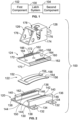
- Figure 1 illustrates a schematic block diagram of a latch system 100 that latchably secures a first component 102 to a second component 104, according to an example of the present disclosure.
- the latch system 100 can be adjustably secured to the first component 102.
- the latch system 100 latchably secures to a reciprocal structure secured to the second component 104.
- the latch system 100 can be adjustably secured to the second component 104, and the reciprocal structure can be secured to the first component 104.
- first and second are merely to identify the number of component.
- the first component can be the second component, and vice versa.
- the latch system 100 includes a base surface that is parallel with a surface of a floor, ground, or the like. As such, the latch system 100 can be horizontally oriented. As another example, the latch system 100 can be orthogonal to the surface of the floor, ground, or the like. Accordingly, the latch system 100 can be vertically oriented. As another example, the latch system 100 can be oriented at any angle between a horizontal orientation and a vertical orientation.
- the first component 102 and the second component 104 can be structures within an internal cabin of a vehicle, such as a commercial aircraft.
- the first component 102 is a header.
- the second component 104 can be a portion of an overhead bin assembly.
- the second component 104 can be a portion of an environmental control system.
- the second component 104 can be a monument within an internal cabin, such as a portion of a lavatory, a closet, a galley section, and/or the like.
- the latch system 100 can be used with various components whether or not within an internal cabin.
- the first component 102 can be a first portion of a barrier, such as a fence
- the second component 104 can be a second portion of the barrier, a gate, or the like. It is to be understood that examples of the first component 102 and the second component 104 are provided, but the latch system 100 can be used with respect to various other components that are configured to be securely latched together.
- the latch system 100 can be moveably adjusted to provide adjustment between the first component 102 and the second component 104. As such, the first component 102 can be adjusted relative to the second component 104, via the latch system 100, without the first component 102 being disconnected or otherwise removed from the second component 104.
- FIG. 2 illustrates an isometric exploded view of the latch system 100, according to an example of the present disclosure.
- the latch system 100 includes a mounting base 120, a spring member 122, a moveable slide plate 124, a housing 126, and a release lever 128 pivotally coupled to the housing 126.
- the mounting base 120 includes a panel 130, which can be a flat, planar sheet.
- the panel 130 can include tabs 132 having through holes 134 that are configured to receive fasteners, such as screws, bolts, or the like.
- the panel 130 is configured to be fixedly secured to a structure, such as a surface of the first component 102 (or optionally, the second component 104), shown in Figure 1 .
- Opposed rails 136 upwardly extend from the panel 130.
- the opposed rails 136 are spaced apart from one another.
- Each rail 136 includes an extension wall 138 extending from the panel 130.
- An orthogonal cross ledge 140 angles inwardly from a top edge of the extension wall 138.
- the cross ledges 140 of the opposed rails 136 are directed toward one another.
- the cross ledge 140 can be perpendicular to the extension wall 138.
- Each of the cross ledges 140 includes an adjustment track 142.
- the adjustment track 142 includes an alternating series of teeth 144 (for example, pins, peaks, posts, or the like) and retainers 146, such as recesses or openings.
- teeth 144 for example, pins, peaks, posts, or the like
- retainers 146 such as recesses or openings.
- only one of the cross ledges 140 may include an adjustment track 142.
- An adjustment channel 150 is defined between the panel 130 and the rails 136.
- the spring member 122 is disposed within the adjustment channel 150.
- the spring member 122 includes a cross strap 152 and arcuate, bowed legs 154 longitudinally extending from the cross strap 152.
- the legs 154 connect to distal feet 156.
- the cross strap 152 and the feet 156 are configured to abut against the panel 130 within the adjustment channel 150, while the legs 154 upwardly bow above the panel 130.
- the spring member 122 provides a spring force that is exerted between the panel 130 and the slide plate 124.
- the spring member 122 can be sized, shaped, and configured differently than shown.
- the spring member 122 can be or include one or more metal coil sections.
- the latch system 100 may not include the spring member 122.
- the slide plate 124 includes a planar main body 158 and lateral ridges 160 extending upwardly from either side of the main body 158. Adjustment tracks 162 upwardly extend from the lateral ridges 160. Like the cross ledges 140 of the mounting base 120, the adjustment tracks 162 includes an alternating series of teeth 164 and retainers 166, such as recesses or openings. Optionally, only one of the ridges 160 may include an adjustment track 162.
- the slide plate 124 is moveably secured within the adjustment channel 150.
- the spring member 122 is disposed between the panel 130 and an underside 170 of the slide plate 124.
- the spring member 122 exerts a spring force between the panel 130 and the slide plate 124, thereby urging the adjustment tracks 162 of the slide plate 124 into the adjustment tracks 142 of the mounting base 120.
- the teeth 164 of the adjustment tracks 162 of the slide plate 124 are retained within the retainers 146 of the adjustment tracks 142 (and the teeth 144 of the adjustment tracks 142 are retained within the retainers 166 of the adjustment tracks 162) to securely lock the slide plate 124 in position relative to the mounting base 120.
- the housing 126 secures onto the slide plate 124.
- the slide plate 124 can include one or more through holes 172 that are configured to receive one or more fasteners that secure a base 174 of the housing 126 to the slide plate 124.
- the slide plate 124 may not be secured to the housing 126 through fasteners. Instead, the slide plate 124 can be fixed to the panel 130 through adhesives, for example.
- the slide plate 124 can be integrally formed with the housing 126.
- the slide plate 124 can form part of the base 174 of the housing 126.
- the housing 126 includes a plurality of walls 176 upwardly extending from the base 174.
- An arm channel 178 is formed between and/or through one or more of the walls 176.
- the arm channel 178 is configured to latchably retain a latch arm of a reciprocal structure, as is known.
- the release lever 128 pivotally couples to the housing 126.
- the release lever 128 is configured to pivot between a securing position, in which the latch arm is securely trapped within the arm channel 178, and a release position, in which the latch arm can be removed from the arm channel 178.
- examples of the present disclosure provide the latch system 100 configured to adjustably secure the first component 102 to the second component 104.
- the latch system 100 includes the mounting base 120.
- the slide plate 124 is moveably coupled to the mounting base 120.
- the slide plate 124 is configured to be slidably adjusted relative to the mounting base 120.
- the housing 126 secured to the slide plate 124.
- the housing 126 includes the arm channel 178 configured to receive and retain a latch arm therein.
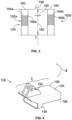
- Figure 3 illustrates a top view of the slide plate 124, according to an example of the present disclosure.
- the adjustment tracks 162a and 162b on opposite ridges 160 can be offset with respect to one another. That is, teeth 164a of the adjustment track 162a are laterally aligned with retainers 166b of the adjustment track 162b. Similarly, teeth 164b of the adjustment track 162b are laterally aligned with retainers 166a of the adjustment track 162a. Laterally aligned refers to being within a common plane 180 that is at a right angle with a longitudinal plane 182 of the slide plate 124, for example.
- the adjustment tracks 142 of the mounting base 120 are similarly offset from one another.
- the teeth 144 of the adjustment tracks 142 can be spaced apart a particular desired distance, such as 1/8 inch.
- the teeth 164 of the adjustment tracks 162 can be spaced the same distance.
- the slide plate 124 includes a first adjustment track 162a and a second adjustment track 162b that are configured to couple to one or more reciprocal adjustment tracks 142 of the mounting base 120.
- the first adjustment track 162a is offset with respect to the second adjustment track 162b.
- the adjustment tracks 162a and 162b may not be offset with respect to one another. Instead, the adjustment tracks 162a and 162b can be axially aligned with respect to one another.
- the dual adjustment tracks 162a and 162b mated with the reciprocal adjustment tracks 142 of the mounting base 120 provide increased retaining strength, whether or not they are offset with respect to one another.
- the slide plate 124 may include only one adjustment track 162 that is configured to mate with a single adjustment track 142 of the mounting base 120.
- Figure 4 illustrates an isometric view of the release lever 128, according to an example of the present disclosure.
- the release lever 128 includes a beam 190 having pivot fins 192 upwardly extending from a top surface 194, and an arm cuff 196 downwardly extending from a bottom surface 198.
- the pivot fin 192 are pivotally coupled to the housing 126, such as through a pin.
- the release lever 128 is configured to pivot in relation to the housing 126.
- a portion of a latch arm (such as a distal tip) is retained between the beam 190 within the arm cuff 196.
- the beam 190 is urged upwardly in the direction of arc A, thereby causing the release lever 128 to rotate, and release the portion of the latch arm from the arm cuff 196.
- the length L of the release lever 128 is longer than prior known release lever 128.
- a length of a prior known release lever is less than 1 1 ⁇ 4 inches (1.25 inches).
- the length L of the release lever 128 can be 1 ⁇ 4 - 1 ⁇ 2 inches (0.25 inches - 0.5 inches) longer than the length of the prior known release lever.
- the length L can be 1 1 ⁇ 2 - 1 3 ⁇ 4 inches (1.5-1.75 inches).
- the greater length L allows for engagement of the release lever 128 over an adjustment range of the latch system 100 (shown in Figures 1 and 2 ).
- the length L can be less than 1.5 inches or greater than 1.75 inches.
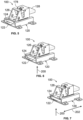
- Figure 5 illustrates an isometric view of the latch system 100.
- the mounting base 120 is fixed to the first component 102.
- a latch arm secured to the second component 104 is latchably secured within the arm channel 178 of the housing 126.
- the spring member 122 exerts a spring force between the slide plate 124 and the mounting base 120, thereby securing the adjustment track(s) 162 of the slide plate 124 to the adjustment track(s) 142 of the mounting base 120 (for example, the teeth 164 of the adjustment track(s) 162 are trapped within the retainers 146 of the adjustment track(s) 142).
- Figure 6 illustrates an isometric view of the latch system 100 being initially moved, according to an example of the present disclosure.
- the first component 102 is urged in the direction of arrow 200 (such as in an upward direction).
- the mounting base 120 moves in response thereto (as the mounting base 120 is fixed to the first component 102.
- the spring member 122 is flattened, and the slide plate 124 remains in position, as it is underneath the housing 126, which is latchably coupled to the latch arm fixed in position in relation to the second component 104.
- the adjustment track(s) 162 of the slide plate 124 disengage from the adjustment track(s) 142 of the mounting base 120.
- the spring member 122 compresses, thereby disengaging the adjustment track(s) 162 of the slide plate from the adjustment track(s) 142 of the mounting base 120.
- Figure 7 illustrates an isometric of the latch system 100 being adjusted, as desired.
- the mounting base 120 (and the first component 102) can be linearly adjusted in the directions of arrow 202, as the slide plate 124 can be slid relative to the housing base 120.
- Adjustment in the directions of arrow 202 occurs while the force is exerted in the direction of arrow 200 so that the adjustment track(s) 162 remain disengaged from the adjustment track(s) 142 until a desired position is released.
- the mounting base 120 can be slid back and forth in the directions of arrow 202, while the upward force in the direction of arrow 200 is maintained.
- the force in the direction of arrow 200 is removed, and the adjustment track(s) 142 re-seat onto the adjustment track(s) 162, such that the teeth 164 of the adjustment track(s) 162 lock into reciprocal retainers 146 of the adjustment track(s) 142, thereby locking the mounting base 120 in position relative to the slide plate 124 (and the housing 126 secured to the slide plate 124).
- the spring member 122 exerts a spring force between the mounting base 120 and the slide plate 124 so that the adjustment track(s) 162 are not inadvertently dislodged from the adjustment track(s) 142 (such as, for example, during periods of turbulence experienced by an aircraft).
- the latch system 100 may not include the spring member 122.
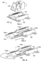
- FIG 8 illustrates an isometric view of the housing 126 removed from the slide plate 124, according to an example of the present disclosure.
- the housing 126 can be secured to the slide plate 124 through one or more fasteners.
- the housing 126 in order to provide finer adjustment of the mounting base 120 relative to the slide plate 124, the housing 126 can first be removed from the slide plate 124. The mounting base 120 can then be urged relative to the slide plate 124 in the direction of arrow 200, thereby disengaging the adjustment tracks 162 from the adjustment tracks 142.
- Figure 9 illustrates an isometric view of the slide plate 124 removed from the mounting base 120, according to an example of the present disclosure. Referring to Figures 1-9 , with continued urging in the direction of arrow 200, such that the adjustment tracks 162 are disengaged from the adjustment tracks 142, the slide plate 124 can be removed from the mounting base 120.
- Figure 10 illustrates an isometric of the slide plate 124 rotated into a different position relative to the mounting base 120. Because the adjustment tracks 162a and 162b of the slide plate 124 are offset from one another (and the adjustment tracks 142a and 142b of the mounting base 120 are similarly offset with respect to one another), the slide plate 124 can be rotated 180 degrees about a central axis 220 and reinserted into the mounting base 120 to provide finer tuned adjustment. For example, adjustment of the slide plate 124 relative to the mounting base 120 can be in 1/8 inch steps. The teeth and retainers of the respective adjustment tracks 142 and 162 are offset to provide a 1/16 inch adjustment when the slide plate 124 is rotated 180 degrees, as described. That is, removing and rotating the slide plate provides adjustment in 1/16 inch increments.
- the slide plate 124 includes a first (plate) adjustment track 162a and a second (plate) adjustment track 162 configured to be selectively secured and unsecured from one or both of a first (base) adjustment track 142a and a second (base) adjustment track 142b (for example, the mounting base 120 may include just one of the adjustment tracks 142a or 142b, or may include both).
- the first adjustment track 162a is offset with respect to the second adjustment track 162b.
- the slide plate 124 is configured to be removed from the mounting base 120.
- the slide plate 124 can then be rotated about the central axis 220 to a different radial position relative to the mounting base 120.
- the slide plate 124 can then be re-inserted into the mounting base 120 at the different radial position.
- FIG 11 illustrates an isometric top view of a header assembly 300, according to an example of the present disclosure.
- the header assembly 300 is an example of a first component 102 (shown in Figure 1 ), or optionally, a second component 104 (shown in Figure 1 ).
- the header assembly 300 is configured to be disposed within an internal cabin of a vehicle, such as a commercial aircraft.
- the header assembly 300 includes a base panel 302, and opposed arcuate walls 304 and 306 upwardly extending from the base panel 302.
- An internal chamber 308 is defined between the base panel 302 and the arcuate walls 304 and 306.
- An insert sheet 310 is disposed over a portion of the base panel 302. Latch systems 100 are mounted onto the insert sheet 310.
- Figure 12 illustrates an isometric top view of a portion of a bin assembly 400 including a beam 402 having a latch arm 404 securely latched to a latch system 100 of the header assembly 300, according to an example of the present disclosure.
- the tie rod 400 is an example of a second component 104 (shown in Figure 1 ), or optionally a first component 102 (shown in Figure 1 ).
- the latch arm 404 is securely latched within the arm channel 178 of the housing 126, as described herein.
- Figure 13 illustrates a lateral view of the header assembly 300 secured to the portion of the bin assembly 400, according to an example of the present disclosure.
- the latch system 100 allows the header assembly 300 to be adjusted relative to the portion of the bin assembly without being disconnected therefrom.
- the header assembly 300 is urged upwardly in the direction of arrow 200 (such as at an outboard side, or optionally an inboard side), thereby disengaging the adjustment track(s) 162 of the slide plate 124 from the reciprocal adjustment track(s) 142 of the mounting base 120.
- the header assembly 300 can then be linearly moved in the direction of arrows 202 to a desired position, as described herein.
- an individual can push up on the header assembly 300 proximate to the portion of the bin assembly 400 in the direction of arrow 200, and then slide to an adjusted position in the direction(s) of arrow 202. After the force in the direction of arrow 200 is released, the weight of the header assembly 300 locks it in place relative to the portion 400.
- the spring member 122 (shown in Figure 2 , for example) reduces vibration between the mounting base 120 and the slide plate 124, and provides constant pressure therebetween to prevent the slide plate 124 from inadvertently moving relative to the mounting base 120 (such as during periods of turbulence during a flight, for example).
- Figure 14 illustrates an isometric front view of a vehicle, such as an aircraft 10, according to an example of the present disclosure.
- the aircraft 10 includes a propulsion system 12 that may include two engines 14, for example.
- the propulsion system 12 may include more engines 14 than shown.
- the engines 14 are carried by wings 16 of the aircraft 10.
- the engines 14 may be carried by a fuselage 18 and/or an empennage 20.
- the empennage 20 may also support horizontal stabilizers 22 and a vertical stabilizer 24.
- the fuselage 18 of the aircraft 10 defines an internal cabin, which may be defined by interior sidewall panels that connect to a ceiling and a floor.
- the internal cabin may include a cockpit, one or more work sections (for example, galleys, personnel carry-on baggage areas, and the like), one or more passenger sections (for example, first class, business class, and economy sections), and an aft section in which an aft rest area assembly may be positioned.
- Overhead stowage bin assemblies may be positioned throughout the internal cabin.
- the internal cabin includes components that can be secured together via the latch system 100, shown and described with respect to Figures 1-13 .
- the internal cabin can include header assemblies coupled to other components, such as valences, overhead stowage bin assemblies, monuments, and the like via one or more latch systems 100.
- examples of the present disclosure may be used with various other vehicles, such as automobiles, buses, locomotives, and train cars, seacraft, spacecraft, and the like.
- Figure 15A illustrates a top plan view of an internal cabin 30 of an aircraft, according to an example of the present disclosure.
- the internal cabin 30 may be within a fuselage 32 of the aircraft.
- one or more fuselage walls may define an interior of the internal cabin 30.
- the interior of the internal cabin 30 is defined by sidewall panels that connect to a ceiling and a floor.
- the sidewall panels include lateral segments that connect to ceiling segments.
- the lateral segments define lateral wall portions, while the ceiling segments define at least portions of the ceiling within the internal cabin 30.
- the internal cabin 30 includes multiple sections, including a front section 33, a first class section 34, a business class section 36, a front galley station 38, an expanded economy or coach section 40, a standard economy or coach section 42, and an aft section 44, which may include multiple lavatories and galley stations. It is to be understood that the internal cabin 30 may include more or less sections than shown. For example, the internal cabin 30 may not include a first class section, and may include more or less galley stations than shown. Each of the sections may be separated by a cabin transition area 46.
- the internal cabin 30 includes two aisles 50 and 52 that lead to the aft section 44.
- the internal cabin 30 may have less or more aisles than shown.
- the internal cabin 30 may include a single aisle that extends through the center of the internal cabin 30 that leads to the aft section 44.
- the internal cabin 30 shown in Figure 15A is an example of an internal cabin of the aircraft 10, shown in Figure 14 .
- Figure 15B illustrates a top plan view of an internal cabin 80 of an aircraft, according to an example of the present disclosure.
- the internal cabin 80 may be within a fuselage 81 of the aircraft.
- one or more fuselage walls may define the interior of the internal cabin 80.
- the internal cabin 80 includes multiple sections, including a main cabin 82 having passenger seat assemblies, and an aft section 85 behind the main cabin 82. It is to be understood that the internal cabin 80 may include more or less sections than shown.
- the internal cabin 80 may include a single aisle 84 that leads to the aft section 85.
- the single aisle 84 may extend through the center of the internal cabin 80 that leads to the aft section 85.
- the single aisle 84 may be coaxially aligned with a central longitudinal plane of the internal cabin 80.
- the internal cabin 30 shown in Figure 15B is an example of an internal cabin of the aircraft 10, shown in Figure 14 .
- the latch system 100 is configured to provide inboard and outboard adjustment of a component, such as a header assembly, relative to another component, such as up to +/- 0.5 inches (or optionally more).
- a component such as a header assembly
- another component such as up to +/- 0.5 inches (or optionally more).
- an individual is able to move the header assembly in outboard and inboard directions (such as in the directions of arrow 202) without disconnecting and lower the header assembly from the other component.
- Figure 16 illustrates a flow chart of a latch method configured to adjustably secure a first component to a second component, according to an example of the present disclosure.
- the latch method includes retaining, at 500, a latch arm 404 within the arm channel 178 of the housing 126 secured to the slide plate 124 that is moveably coupled to the mounting base 120; and slidably adjusting, at 502, the slide plate 124 relative to the mounting base 120.
- the first component 102 is a header assembly 300 within an internal cabin of a vehicle.
- the second component 104 is a structure (such as a portion of a bin assembly) that latchably secures to the header assembly 300 through the latch system 100.
- the mounting base 120 of the latch system 100 is securely fixed to one of the header assembly 300 or the structure.
- the method also includes removably coupling one or more adjustment tracks 162 of the slide plate 124 to one or more reciprocal adjustment tracks 142 of the mounting base 120.
- a first adjustment track 162a and a second adjustment track 162b removably couple to the one or more reciprocal adjustment tracks 142 of the mounting base 120.
- the first adjustment track 162a is offset with respect to the second adjustment track 162b.
- said removably coupling includes removing the slide plate 124 from the mounting base 120; rotating the slide plate 124 about the axis 220 to a different radial position relative to the mounting base 120; and re-inserting the slide plate 124 into the mounting base 120 at the different radial position.
- the latch method also includes exerting, by the spring member 122 disposed between the mounting base 120 and the slide plate 124, a spring force between the mounting base 120 and the slide plate 124.
- said slidably adjusting includes urging the mounting base 120 upwardly in relation to the slide plate 124; and sliding the mounting base 120 relative to the slide plate 124 during said urging.
- examples of the present disclosure provide latch systems and method that allow for adjustment of components after they are connected together.
- the latch systems and methods allow an individual to adjust a header assembly without removing the header assembly from another component, or preforming additional rework.
- a structure, limitation, or element that is "configured to” perform a task or operation is particularly structurally formed, constructed, or adapted in a manner corresponding to the task or operation.
- an object that is merely capable of being modified to perform the task or operation is not “configured to” perform the task or operation as used herein.
Landscapes
- Engineering & Computer Science (AREA)
- General Engineering & Computer Science (AREA)
- Aviation & Aerospace Engineering (AREA)
- Mechanical Engineering (AREA)
- Connection Of Plates (AREA)
Abstract
Description
- Examples of the present disclosure generally relate to latch systems, and more particularly to adjustable latch systems configured to adjustably coupled components together.
- Commercial aircraft typically include an internal cabin that may be divided into numerous sections. A cockpit is generally separated from a passenger cabin, which may include a first class section, a business class section, and a coach section. The passenger cabin may also include one or more work areas for flight personnel, such as galleys, which may include food and beverage storage structures. One or more aisles pass through the passenger cabin and connect each of the passenger sections to one or more paths to one or more doors of the aircraft.
- Each passenger section may be separated from an adjacent passenger section by a cabin transition area, which may include one or more monuments, such as walls, work stations, or the like. Curtains may be used to separate sections of an aircraft for a variety of reasons, including class separation, privacy, work areas, and the like. For example, a cabin transition area between a business class section and a coach section may include a curtain assembly within an aisle. A curtain moveably connected to a curtain track that spans over any aisle may be selectively opened and closed. When opened, such as during a boarding process, passengers may pass from one section to another section, such as from the business class section to the coach section. During flight, the curtain may be closed to indicate that passengers are not allowed to pass (or at least discouraged from passing) from the coach section into the business class section.
- During flights, lights within one passenger section may be on, while lights within an adjacent passenger section may be off. Some aircraft include a header over a curtain section that is configured to limit or shade light between sections. A known header includes a panel formed of a solid material. The solid header typically straddles onto an upper curtain track of the curtain in a linear fashion. For example, the solid header may straddle either side of a curtain track and be secured thereto. Another known header is configured to block or otherwise limit passage of light over curtain assemblies within an interior cabin of an aircraft. The header is sturdy, robust, and aesthetically agreeable in that it may contour and blend with inboard or outboard structures (such as through smooth, arcuate transitions).
- Typically, a header is secured to another structure, such as a portion of a bin assembly, a portion of an environmental control system, a monument, and/or the like by a plurality of latches, which are fixed in position relative to the header. However, known latches constrain the position of the header position. Once the header is installed, there is typically no ability to adjust the position of the header. As such, if an individual finds that the header is too far away or too close to another structure after installation, the header typically needs to be removed from the other structure, and the latches themselves need to be removed and/or reworked in relation to the header.
- A need exists for an adjustable latch system. Further, a need exists for a latch system that is configured to latchably secure a first component to a second component and for adjustment of the first component in relation to the second component after the first component is latchably secured to the first component. Also, a need exists for a latch system that allows an individual to adjust a header without removing the header or preforming additional rework.
- With those needs in mind, certain examples of the present disclosure provide a latch system configured to adjustably secure a first component to a second component. The latch system includes a mounting base. A slide plate is moveably coupled to the mounting base. The slide plate is configured to be slidably adjusted relative to the mounting base. A housing is secured to the slide plate. The housing includes an arm channel configured to receive and retain a latch arm.
- In at least one example, the first component is a header assembly within an internal cabin of a vehicle. The second component is a structure that latchably secures to the header assembly through the latch system. The mounting base of the latch system is securely fixed to one of the header assembly or the structure.
- In at least one example, the slide plate includes one or more adjustment tracks configured to removably couple to one or more reciprocal adjustment tracks of the mounting base. For example, the one or more adjustment tracks of the slide plate include a first adjustment track and a second adjustment track configured to removably couple to the one or more reciprocal adjustment tracks of the mounting base. In at least one further example, the first adjustment track is offset with respect to the second adjustment track. In at least one example, the slide plate is configured to be removed from the mounting base, rotated about an axis to a different radial position relative to the mounting base, and re-inserted into the mounting base at the different radial position.
- In at least one example, a spring member is disposed between the mounting base and the slide plate. The spring member exerts a spring force between the mounting base and the slide plate. In at least one further example, the mounting base includes an adjustment channel. The slide plate and the spring member are disposed within the adjustment channel.
- In at least one example, a release lever is pivotally coupled to the housing. The release lever is configured to pivot between a securing position, in which the latch arm is securely trapped within the arm channel, and a release position, in which the latch arm is removable from the arm channel. As a further example, the release lever has a length that is at least 1.5 inches.
- In at least one example, the latch system is configured to be adjusted by urging the mounting base upwardly in relation to the slide plate, and sliding the mounting base in relation to the slide plate while the mounting base is urged upwardly in relation to the slide plate.
- Certain examples of the present disclosure provide a latch method configured to adjustably secure a first component to a second component. The latch method includes retaining a latch arm within an arm channel of a housing secured to a slide plate that is moveably coupled to a mounting base; and slidably adjusting the slide plate relative to the mounting base.
- Certain examples of the present disclosure provide a vehicle including an internal cabin, a first component within the internal cabin, a second component within the internal cabin, and a latch system that adjustably secures the first component to the second component, as described herein.
-
-
Figure 1 illustrates a schematic block diagram of a latch system that latchably secures a first component to a second component, according to an example of the present disclosure. -
Figure 2 illustrates an isometric exploded view of a latch system, according to an example of the present disclosure. -
Figure 3 illustrates a top view of a slide plate, according to an example of the present disclosure. -
Figure 4 illustrates an isometric view of a release lever, according to an example of the present disclosure. -
Figure 5 illustrates an isometric view of the latch system. -
Figure 6 illustrates an isometric view of the latch system being initially moved, according to an example of the present disclosure. -
Figure 7 illustrates an isometric of the latch system being adjusted, as desired. -
Figure 8 illustrates an isometric view of a housing removed from a slide plate, according to an example of the present disclosure. -
Figure 9 illustrates an isometric view of the slide plate removed from a mounting base, according to an example of the present disclosure. -
Figure 10 illustrates an isometric of the slide plate rotated into a different position relative to the mounting base. -
Figure 11 illustrates an isometric top view of a header assembly, according to an example of the present disclosure. -
Figure 12 illustrates an isometric top view of a portion of a bin assembly including a beam having a latch arm securely latched to a latch system of the header assembly, according to an example of the present disclosure. -
Figure 13 illustrates a lateral view of the header assembly secured to a portion of a bin assembly, according to an example of the present disclosure. -
Figure 14 illustrates an isometric front view of an aircraft, according to an example of the present disclosure. -
Figure 15A illustrates a top plan view of an internal cabin of an aircraft. -
Figure 15B illustrates a top plan view of an internal cabin of an aircraft. -
Figure 16 illustrates a flow chart of a latch method configured to adjustably secure a first component to a second component, according to an example of the present disclosure. - The foregoing summary, as well as the following detailed description of certain examples will be better understood when read in conjunction with the appended drawings. As used herein, an element or step recited in the singular and preceded by the word "a" or "an" should be understood as not necessarily excluding the plural of the elements or steps. Further, references to "one example" are not intended to be interpreted as excluding the existence of additional examples that also incorporate the recited features. Moreover, unless explicitly stated to the contrary, examples "comprising" or "having" an element or a plurality of elements having a particular condition can include additional elements not having that condition.
- Certain examples of the present disclosure provide a latch system that allows an individual to adjust a first component (such as a header) in relation to a second component (such as a portion of a valence, a bin assembly, a portion of an environment control system, a portion of a monument, or the like) without removing the first component from the second component, or preforming additional rework. For example, if the gap between a header and a valance is out of tolerance, an individual can push up on the header, and slide the light header inboard or outboard to achieve a desired spacing between the header and the valence.
- In at least one example, the latch system allows an individual installing a header (for example, a light limiting header) to adjust an inboard/outboard location of the header by simply pushing up on the header and sliding the header inboard or outboard, as desired. The latch system allows for the header to be adjusted in relation to another component (such as a valence, overhead stowage bin assembly, monument, or the like) without removing the header from the other component. As such, the latch system provides for efficient and effective installation and manufacturing, thereby reducing labor time and costs.
- Certain examples of the present disclosure provide an adjustable latch system for adjusting a gap between adjacent panels or other structures. The latch system includes an adjustable slide plate, a housing mount, and a compliant spring member. In at least one example, the latch system can provide at least 1/2 inch of total linear adjustable movement, can move in 1/8 inch or 1/16 inch increments. In operation, and when assembled, an individual can push upwardly on a header panel, which releases the adjustable slide plate from the housing mount to facilitate lateral sliding of the header (relative to an adjacent panel), and then release pressure from the header, which automatically locks the adjustable slide plate to the housing mount (due to gravity and friction and locking of teeth or pins on the slide plate to slots on the housing). The compliant spring member applies pressure between the slide plate and the housing to prevent accidental unlocking of the latch due to turbulence induced vibrations. The latch system and method of adjustment facilitate blind adjustment capability by an individual, which is advantageous because prior known solutions require manual adjustment of the latch and/or removal panels to facilitate micro adjustments.
-
Figure 1 illustrates a schematic block diagram of alatch system 100 that latchably secures afirst component 102 to asecond component 104, according to an example of the present disclosure. Thelatch system 100 can be adjustably secured to thefirst component 102. Thelatch system 100 latchably secures to a reciprocal structure secured to thesecond component 104. Optionally, thelatch system 100 can be adjustably secured to thesecond component 104, and the reciprocal structure can be secured to thefirst component 104. It is to be understood that the terms first and second are merely to identify the number of component. The first component can be the second component, and vice versa. - In at least one example, the
latch system 100 includes a base surface that is parallel with a surface of a floor, ground, or the like. As such, thelatch system 100 can be horizontally oriented. As another example, thelatch system 100 can be orthogonal to the surface of the floor, ground, or the like. Accordingly, thelatch system 100 can be vertically oriented. As another example, thelatch system 100 can be oriented at any angle between a horizontal orientation and a vertical orientation. - The
first component 102 and thesecond component 104 can be structures within an internal cabin of a vehicle, such as a commercial aircraft. As one example, thefirst component 102 is a header. Thesecond component 104 can be a portion of an overhead bin assembly. As another example, thesecond component 104 can be a portion of an environmental control system. As another example, thesecond component 104 can be a monument within an internal cabin, such as a portion of a lavatory, a closet, a galley section, and/or the like. - Optionally, the
latch system 100 can be used with various components whether or not within an internal cabin. For example, thefirst component 102 can be a first portion of a barrier, such as a fence, and thesecond component 104 can be a second portion of the barrier, a gate, or the like. It is to be understood that examples of thefirst component 102 and thesecond component 104 are provided, but thelatch system 100 can be used with respect to various other components that are configured to be securely latched together. - As described herein, after the
first component 102 is latchably secured to thesecond component 104 by thelatch system 100, thelatch system 100 can be moveably adjusted to provide adjustment between thefirst component 102 and thesecond component 104. As such, thefirst component 102 can be adjusted relative to thesecond component 104, via thelatch system 100, without thefirst component 102 being disconnected or otherwise removed from thesecond component 104. -
Figure 2 illustrates an isometric exploded view of thelatch system 100, according to an example of the present disclosure. Thelatch system 100 includes a mountingbase 120, aspring member 122, amoveable slide plate 124, ahousing 126, and arelease lever 128 pivotally coupled to thehousing 126. - The mounting
base 120 includes apanel 130, which can be a flat, planar sheet. Thepanel 130 can includetabs 132 having throughholes 134 that are configured to receive fasteners, such as screws, bolts, or the like. Thepanel 130 is configured to be fixedly secured to a structure, such as a surface of the first component 102 (or optionally, the second component 104), shown inFigure 1 .Opposed rails 136 upwardly extend from thepanel 130. The opposed rails 136 are spaced apart from one another. Eachrail 136 includes anextension wall 138 extending from thepanel 130. Anorthogonal cross ledge 140 angles inwardly from a top edge of theextension wall 138. The cross ledges 140 of theopposed rails 136 are directed toward one another. Thecross ledge 140 can be perpendicular to theextension wall 138. - Each of the
cross ledges 140 includes anadjustment track 142. Theadjustment track 142 includes an alternating series of teeth 144 (for example, pins, peaks, posts, or the like) andretainers 146, such as recesses or openings. Optionally, only one of thecross ledges 140 may include anadjustment track 142. - An
adjustment channel 150 is defined between thepanel 130 and therails 136. Thespring member 122 is disposed within theadjustment channel 150. - In at least one example, the
spring member 122 includes across strap 152 and arcuate, bowedlegs 154 longitudinally extending from thecross strap 152. Thelegs 154 connect todistal feet 156. Thecross strap 152 and thefeet 156 are configured to abut against thepanel 130 within theadjustment channel 150, while thelegs 154 upwardly bow above thepanel 130. Thespring member 122 provides a spring force that is exerted between thepanel 130 and theslide plate 124. Optionally, thespring member 122 can be sized, shaped, and configured differently than shown. For example, thespring member 122 can be or include one or more metal coil sections. Alternatively, thelatch system 100 may not include thespring member 122. - The
slide plate 124 includes a planarmain body 158 andlateral ridges 160 extending upwardly from either side of themain body 158. Adjustment tracks 162 upwardly extend from thelateral ridges 160. Like thecross ledges 140 of the mountingbase 120, the adjustment tracks 162 includes an alternating series ofteeth 164 andretainers 166, such as recesses or openings. Optionally, only one of theridges 160 may include anadjustment track 162. - The
slide plate 124 is moveably secured within theadjustment channel 150. Thespring member 122 is disposed between thepanel 130 and anunderside 170 of theslide plate 124. Thespring member 122 exerts a spring force between thepanel 130 and theslide plate 124, thereby urging the adjustment tracks 162 of theslide plate 124 into the adjustment tracks 142 of the mountingbase 120. Theteeth 164 of the adjustment tracks 162 of theslide plate 124 are retained within theretainers 146 of the adjustment tracks 142 (and theteeth 144 of the adjustment tracks 142 are retained within theretainers 166 of the adjustment tracks 162) to securely lock theslide plate 124 in position relative to the mountingbase 120. - The
housing 126 secures onto theslide plate 124. For example, theslide plate 124 can include one or more throughholes 172 that are configured to receive one or more fasteners that secure abase 174 of thehousing 126 to theslide plate 124. Optionally, theslide plate 124 may not be secured to thehousing 126 through fasteners. Instead, theslide plate 124 can be fixed to thepanel 130 through adhesives, for example. As another example, theslide plate 124 can be integrally formed with thehousing 126. For example, theslide plate 124 can form part of thebase 174 of thehousing 126. - The
housing 126 includes a plurality ofwalls 176 upwardly extending from thebase 174. Anarm channel 178 is formed between and/or through one or more of thewalls 176. Thearm channel 178 is configured to latchably retain a latch arm of a reciprocal structure, as is known. Therelease lever 128 pivotally couples to thehousing 126. Therelease lever 128 is configured to pivot between a securing position, in which the latch arm is securely trapped within thearm channel 178, and a release position, in which the latch arm can be removed from thearm channel 178. - Referring to
Figures 1 and 2 , as described herein, examples of the present disclosure provide thelatch system 100 configured to adjustably secure thefirst component 102 to thesecond component 104. Thelatch system 100 includes the mountingbase 120. Theslide plate 124 is moveably coupled to the mountingbase 120. Theslide plate 124 is configured to be slidably adjusted relative to the mountingbase 120. Thehousing 126 secured to theslide plate 124. Thehousing 126 includes thearm channel 178 configured to receive and retain a latch arm therein. -
Figure 3 illustrates a top view of theslide plate 124, according to an example of the present disclosure. As shown, theadjustment tracks opposite ridges 160 can be offset with respect to one another. That is,teeth 164a of theadjustment track 162a are laterally aligned withretainers 166b of theadjustment track 162b. Similarly,teeth 164b of theadjustment track 162b are laterally aligned withretainers 166a of theadjustment track 162a. Laterally aligned refers to being within acommon plane 180 that is at a right angle with alongitudinal plane 182 of theslide plate 124, for example. The adjustment tracks 142 of the mountingbase 120 are similarly offset from one another. - Referring to
Figures 2 and3 , theteeth 144 of the adjustment tracks 142 can be spaced apart a particular desired distance, such as 1/8 inch. Similarly, theteeth 164 of the adjustment tracks 162 can be spaced the same distance. By offsetting thetracks tracks 142 of the mounting base), theslide plate 124 can be removed from the mountingbase 120, and rotated 180 degrees, in order to provide finer adjustment, such as distances of 1/16 inch. - In at least one example, the
slide plate 124 includes afirst adjustment track 162a and asecond adjustment track 162b that are configured to couple to one or more reciprocal adjustment tracks 142 of the mountingbase 120. In at least one example, thefirst adjustment track 162a is offset with respect to thesecond adjustment track 162b. - Alternatively, the
adjustment tracks adjustment tracks dual adjustment tracks base 120 provide increased retaining strength, whether or not they are offset with respect to one another. Also, alternatively, theslide plate 124 may include only oneadjustment track 162 that is configured to mate with asingle adjustment track 142 of the mountingbase 120. -
Figure 4 illustrates an isometric view of therelease lever 128, according to an example of the present disclosure. Therelease lever 128 includes abeam 190 havingpivot fins 192 upwardly extending from atop surface 194, and anarm cuff 196 downwardly extending from abottom surface 198. - Referring to
Figures 2 and4 , thepivot fin 192 are pivotally coupled to thehousing 126, such as through a pin. In this manner, therelease lever 128 is configured to pivot in relation to thehousing 126. In the securing position, a portion of a latch arm (such as a distal tip) is retained between thebeam 190 within thearm cuff 196. In order to release the latch arm. Thebeam 190 is urged upwardly in the direction of arc A, thereby causing therelease lever 128 to rotate, and release the portion of the latch arm from thearm cuff 196. - The length L of the
release lever 128 is longer than prior knownrelease lever 128. For example, a length of a prior known release lever is less than 1 ¼ inches (1.25 inches). However, the length L of therelease lever 128 can be ¼ - ½ inches (0.25 inches - 0.5 inches) longer than the length of the prior known release lever. For example, the length L can be 1 ½ - 1 ¾ inches (1.5-1.75 inches). The greater length L allows for engagement of therelease lever 128 over an adjustment range of the latch system 100 (shown inFigures 1 and 2 ). Optionally, the length L can be less than 1.5 inches or greater than 1.75 inches. -
Figure 5 illustrates an isometric view of thelatch system 100. Referring toFigures 1-5 , the mountingbase 120 is fixed to thefirst component 102. A latch arm secured to thesecond component 104 is latchably secured within thearm channel 178 of thehousing 126. Thespring member 122 exerts a spring force between theslide plate 124 and the mountingbase 120, thereby securing the adjustment track(s) 162 of theslide plate 124 to the adjustment track(s) 142 of the mounting base 120 (for example, theteeth 164 of the adjustment track(s) 162 are trapped within theretainers 146 of the adjustment track(s) 142). -
Figure 6 illustrates an isometric view of thelatch system 100 being initially moved, according to an example of the present disclosure. Referring toFigures 1-6 , in order to linearly adjust thelatch system 100, thefirst component 102 is urged in the direction of arrow 200 (such as in an upward direction). As thefirst component 102 is moved in the direction ofarrow 200, the mountingbase 120 moves in response thereto (as the mountingbase 120 is fixed to thefirst component 102. In response, thespring member 122 is flattened, and theslide plate 124 remains in position, as it is underneath thehousing 126, which is latchably coupled to the latch arm fixed in position in relation to thesecond component 104. Accordingly, the adjustment track(s) 162 of theslide plate 124 disengage from the adjustment track(s) 142 of the mountingbase 120. As shown inFigure 6 , as the mountingbase 120 is pushed up, thespring member 122 compresses, thereby disengaging the adjustment track(s) 162 of the slide plate from the adjustment track(s) 142 of the mountingbase 120. -
Figure 7 illustrates an isometric of thelatch system 100 being adjusted, as desired. Referring toFigures 1-7 , with the force in the direction ofarrow 200 being applied, such that the adjustment track(s) 162 are no longer locked in place with respect to the adjustment track(s) 142 of the mountingbase 120, the mounting base 120 (and the first component 102) can be linearly adjusted in the directions ofarrow 202, as theslide plate 124 can be slid relative to thehousing base 120. Adjustment in the directions ofarrow 202 occurs while the force is exerted in the direction ofarrow 200 so that the adjustment track(s) 162 remain disengaged from the adjustment track(s) 142 until a desired position is released. The mountingbase 120 can be slid back and forth in the directions ofarrow 202, while the upward force in the direction ofarrow 200 is maintained. - At the desired position, the force in the direction of
arrow 200 is removed, and the adjustment track(s) 142 re-seat onto the adjustment track(s) 162, such that theteeth 164 of the adjustment track(s) 162 lock intoreciprocal retainers 146 of the adjustment track(s) 142, thereby locking the mountingbase 120 in position relative to the slide plate 124 (and thehousing 126 secured to the slide plate 124). Thespring member 122 exerts a spring force between the mountingbase 120 and theslide plate 124 so that the adjustment track(s) 162 are not inadvertently dislodged from the adjustment track(s) 142 (such as, for example, during periods of turbulence experienced by an aircraft). Alternatively, thelatch system 100 may not include thespring member 122. -
Figure 8 illustrates an isometric view of thehousing 126 removed from theslide plate 124, according to an example of the present disclosure. As noted, thehousing 126 can be secured to theslide plate 124 through one or more fasteners. Referring toFigures 1-8 , in order to provide finer adjustment of the mountingbase 120 relative to theslide plate 124, thehousing 126 can first be removed from theslide plate 124. The mountingbase 120 can then be urged relative to theslide plate 124 in the direction ofarrow 200, thereby disengaging the adjustment tracks 162 from the adjustment tracks 142. -
Figure 9 illustrates an isometric view of theslide plate 124 removed from the mountingbase 120, according to an example of the present disclosure. Referring toFigures 1-9 , with continued urging in the direction ofarrow 200, such that the adjustment tracks 162 are disengaged from the adjustment tracks 142, theslide plate 124 can be removed from the mountingbase 120. -
Figure 10 illustrates an isometric of theslide plate 124 rotated into a different position relative to the mountingbase 120. Because theadjustment tracks slide plate 124 are offset from one another (and theadjustment tracks base 120 are similarly offset with respect to one another), theslide plate 124 can be rotated 180 degrees about acentral axis 220 and reinserted into the mountingbase 120 to provide finer tuned adjustment. For example, adjustment of theslide plate 124 relative to the mountingbase 120 can be in 1/8 inch steps. The teeth and retainers of the respective adjustment tracks 142 and 162 are offset to provide a 1/16 inch adjustment when theslide plate 124 is rotated 180 degrees, as described. That is, removing and rotating the slide plate provides adjustment in 1/16 inch increments. - As described, in at least one example, the
slide plate 124 includes a first (plate)adjustment track 162a and a second (plate)adjustment track 162 configured to be selectively secured and unsecured from one or both of a first (base)adjustment track 142a and a second (base)adjustment track 142b (for example, the mountingbase 120 may include just one of theadjustment tracks first adjustment track 162a is offset with respect to thesecond adjustment track 162b. - As described with respect to
Figures 8-10 , theslide plate 124 is configured to be removed from the mountingbase 120. Theslide plate 124 can then be rotated about thecentral axis 220 to a different radial position relative to the mountingbase 120. Theslide plate 124 can then be re-inserted into the mountingbase 120 at the different radial position. -
Figure 11 illustrates an isometric top view of aheader assembly 300, according to an example of the present disclosure. Theheader assembly 300 is an example of a first component 102 (shown inFigure 1 ), or optionally, a second component 104 (shown inFigure 1 ). Theheader assembly 300 is configured to be disposed within an internal cabin of a vehicle, such as a commercial aircraft. - The
header assembly 300 includes abase panel 302, and opposedarcuate walls base panel 302. Aninternal chamber 308 is defined between thebase panel 302 and thearcuate walls insert sheet 310 is disposed over a portion of thebase panel 302.Latch systems 100 are mounted onto theinsert sheet 310. -
Figure 12 illustrates an isometric top view of a portion of abin assembly 400 including abeam 402 having alatch arm 404 securely latched to alatch system 100 of theheader assembly 300, according to an example of the present disclosure. Thetie rod 400 is an example of a second component 104 (shown inFigure 1 ), or optionally a first component 102 (shown inFigure 1 ). Thelatch arm 404 is securely latched within thearm channel 178 of thehousing 126, as described herein. -
Figure 13 illustrates a lateral view of theheader assembly 300 secured to the portion of thebin assembly 400, according to an example of the present disclosure. Referring toFigures 1-13 , thelatch system 100 allows theheader assembly 300 to be adjusted relative to the portion of the bin assembly without being disconnected therefrom. As described herein, in order to adjust theheader assembly 300 relative to theportion 400, theheader assembly 300 is urged upwardly in the direction of arrow 200 (such as at an outboard side, or optionally an inboard side), thereby disengaging the adjustment track(s) 162 of theslide plate 124 from the reciprocal adjustment track(s) 142 of the mountingbase 120. With the force in the direction ofarrow 200 being applied, theheader assembly 300 can then be linearly moved in the direction ofarrows 202 to a desired position, as described herein. - If adjustment is needed after the
header assembly 300 is connected to the portion of thebin assembly 400, an individual can push up on theheader assembly 300 proximate to the portion of thebin assembly 400 in the direction ofarrow 200, and then slide to an adjusted position in the direction(s) ofarrow 202. After the force in the direction ofarrow 200 is released, the weight of theheader assembly 300 locks it in place relative to theportion 400. The spring member 122 (shown inFigure 2 , for example) reduces vibration between the mountingbase 120 and theslide plate 124, and provides constant pressure therebetween to prevent theslide plate 124 from inadvertently moving relative to the mounting base 120 (such as during periods of turbulence during a flight, for example). -
Figure 14 illustrates an isometric front view of a vehicle, such as anaircraft 10, according to an example of the present disclosure. Theaircraft 10 includes apropulsion system 12 that may include twoengines 14, for example. Optionally, thepropulsion system 12 may includemore engines 14 than shown. Theengines 14 are carried bywings 16 of theaircraft 10. In other examples, theengines 14 may be carried by afuselage 18 and/or anempennage 20. Theempennage 20 may also supporthorizontal stabilizers 22 and avertical stabilizer 24. - The
fuselage 18 of theaircraft 10 defines an internal cabin, which may be defined by interior sidewall panels that connect to a ceiling and a floor. The internal cabin may include a cockpit, one or more work sections (for example, galleys, personnel carry-on baggage areas, and the like), one or more passenger sections (for example, first class, business class, and economy sections), and an aft section in which an aft rest area assembly may be positioned. Overhead stowage bin assemblies may be positioned throughout the internal cabin. - The internal cabin includes components that can be secured together via the
latch system 100, shown and described with respect toFigures 1-13 . For example, the internal cabin can include header assemblies coupled to other components, such as valences, overhead stowage bin assemblies, monuments, and the like via one ormore latch systems 100. - Alternatively, instead of an aircraft, examples of the present disclosure may be used with various other vehicles, such as automobiles, buses, locomotives, and train cars, seacraft, spacecraft, and the like.
-
Figure 15A illustrates a top plan view of aninternal cabin 30 of an aircraft, according to an example of the present disclosure. Theinternal cabin 30 may be within afuselage 32 of the aircraft. For example, one or more fuselage walls may define an interior of theinternal cabin 30. The interior of theinternal cabin 30 is defined by sidewall panels that connect to a ceiling and a floor. The sidewall panels include lateral segments that connect to ceiling segments. The lateral segments define lateral wall portions, while the ceiling segments define at least portions of the ceiling within theinternal cabin 30. - The
internal cabin 30 includes multiple sections, including afront section 33, afirst class section 34, abusiness class section 36, afront galley station 38, an expanded economy orcoach section 40, a standard economy orcoach section 42, and anaft section 44, which may include multiple lavatories and galley stations. It is to be understood that theinternal cabin 30 may include more or less sections than shown. For example, theinternal cabin 30 may not include a first class section, and may include more or less galley stations than shown. Each of the sections may be separated by acabin transition area 46. - As shown in
Figure 15A , theinternal cabin 30 includes twoaisles aft section 44. Optionally, theinternal cabin 30 may have less or more aisles than shown. For example, theinternal cabin 30 may include a single aisle that extends through the center of theinternal cabin 30 that leads to theaft section 44. - The
internal cabin 30 shown inFigure 15A is an example of an internal cabin of theaircraft 10, shown inFigure 14 . -
Figure 15B illustrates a top plan view of aninternal cabin 80 of an aircraft, according to an example of the present disclosure. Theinternal cabin 80 may be within afuselage 81 of the aircraft. For example, one or more fuselage walls may define the interior of theinternal cabin 80. Theinternal cabin 80 includes multiple sections, including amain cabin 82 having passenger seat assemblies, and anaft section 85 behind themain cabin 82. It is to be understood that theinternal cabin 80 may include more or less sections than shown. - The
internal cabin 80 may include asingle aisle 84 that leads to theaft section 85. Thesingle aisle 84 may extend through the center of theinternal cabin 80 that leads to theaft section 85. For example, thesingle aisle 84 may be coaxially aligned with a central longitudinal plane of theinternal cabin 80. - The
internal cabin 30 shown inFigure 15B is an example of an internal cabin of theaircraft 10, shown inFigure 14 . - Referring to
Figures 1-15B , thelatch system 100 is configured to provide inboard and outboard adjustment of a component, such as a header assembly, relative to another component, such as up to +/- 0.5 inches (or optionally more). After the header assembly is installed, an individual is able to move the header assembly in outboard and inboard directions (such as in the directions of arrow 202) without disconnecting and lower the header assembly from the other component. -
Figure 16 illustrates a flow chart of a latch method configured to adjustably secure a first component to a second component, according to an example of the present disclosure. Referring toFigures 1-16 , the latch method includes retaining, at 500, alatch arm 404 within thearm channel 178 of thehousing 126 secured to theslide plate 124 that is moveably coupled to the mountingbase 120; and slidably adjusting, at 502, theslide plate 124 relative to the mountingbase 120. - In at least one example, the
first component 102 is aheader assembly 300 within an internal cabin of a vehicle. Thesecond component 104 is a structure (such as a portion of a bin assembly) that latchably secures to theheader assembly 300 through thelatch system 100. The mountingbase 120 of thelatch system 100 is securely fixed to one of theheader assembly 300 or the structure. - In at least one example, the method also includes removably coupling one or more adjustment tracks 162 of the
slide plate 124 to one or more reciprocal adjustment tracks 142 of the mountingbase 120. For example, afirst adjustment track 162a and asecond adjustment track 162b removably couple to the one or more reciprocal adjustment tracks 142 of the mountingbase 120. - In at least one example, the
first adjustment track 162a is offset with respect to thesecond adjustment track 162b. Further, in at least one example, said removably coupling includes removing theslide plate 124 from the mountingbase 120; rotating theslide plate 124 about theaxis 220 to a different radial position relative to the mountingbase 120; and re-inserting theslide plate 124 into the mountingbase 120 at the different radial position. - In at least one example, the latch method also includes exerting, by the
spring member 122 disposed between the mountingbase 120 and theslide plate 124, a spring force between the mountingbase 120 and theslide plate 124. - In at least one example, said slidably adjusting includes urging the mounting
base 120 upwardly in relation to theslide plate 124; and sliding the mountingbase 120 relative to theslide plate 124 during said urging. - Further, the disclosure comprises examples according to the following clauses:
- Clause 1. A latch system configured to adjustably secure a first component to a second component, the latch system comprising:
- a mounting base;
- a slide plate moveably coupled to the mounting base, wherein the slide plate is configured to be slidably adjusted relative to the mounting base; and
- a housing secured to the slide plate, wherein the housing comprises an arm channel configured to receive and retain a latch arm.
- Clause 2. The latch system of Clause 1, wherein the first component is a header assembly within an internal cabin of a vehicle, wherein the second component is a structure that latchably secures to the header assembly through the latch system, and wherein the mounting base of the latch system is securely fixed to one of the header assembly or the structure.
- Clause 3. The latch system of Clauses 1 or 2, wherein the slide plate comprises one or more adjustment tracks configured to removably couple to one or more reciprocal adjustment tracks of the mounting base.
- Clause 4. The latch system of Clause 3, wherein the one or more adjustment tracks of the slide plate comprise a first adjustment track and a second adjustment track configured to removably couple to the one or more reciprocal adjustment tracks of the mounting base.
- Clause 5. The latch system of Clause 4, wherein the first adjustment track is offset with respect to the second adjustment track.
- Clause 6. The latch system of Clause 5, wherein the slide plate is configured to be removed from the mounting base, rotated about an axis to a different radial position relative to the mounting base, and re-inserted into the mounting base at the different radial position.
- Clause 7. The latch system of any of Clauses 1-6, further comprising a spring member disposed between the mounting base and the slide plate, wherein the spring member exerts a spring force between the mounting base and the slide plate.
- Clause 8. The latch system of Clause 7, wherein the mounting base comprises an adjustment channel, wherein the slide plate and the spring member are disposed within the adjustment channel.
- Clause 9. The latch system of any of Clauses 1-8, further comprising a release lever pivotally coupled to the housing, wherein the release lever is configured to pivot between a securing position, in which the latch arm is securely trapped within the arm channel, and a release position, in which the latch arm is removable from the arm channel.
-
Clause 10. The latch system of Clause 9, wherein the release lever has a length that is at least 1.5 inches. - Clause 11. The latch system of any of Clauses 1-10, wherein the latch system is configured to be adjusted by urging the mounting base upwardly in relation to the slide plate, and sliding the mounting base in relation to the slide plate while the mounting base is urged upwardly in relation to the slide plate.
-
Clause 12. A latch method configured to adjustably secure a first component to a second component, the latch method comprising:- retaining a latch arm within an arm channel of a housing secured to a slide plate that is moveably coupled to a mounting base; and
- slidably adjusting the slide plate relative to the mounting base.
- Clause 13. The latch method of
Clause 12, wherein the first component is a header assembly within an internal cabin of a vehicle, wherein the second component is a structure that latchably secures to the header assembly through the latch system, and wherein the mounting base of the latch system is securely fixed to one of the header assembly or the structure. -
Clause 14. The latch method ofClauses 12 or 13, further comprising removably coupling one or more adjustment tracks of the slide plate to one or more reciprocal adjustment tracks of the mounting base. - Clause 15. The latch method of
Clause 14, wherein the one or more adjustment tracks of the slide plate comprise a first adjustment track and a second adjustment track that removably couple to the one or more reciprocal adjustment tracks of the mounting base. -
Clause 16. The latch method of Clause 15, wherein the first adjustment track is offset with respect to the second adjustment track. - Clause 17. The latch method of
Clause 16, wherein said removably coupling comprises:- removing the slide plate from the mounting base;
- rotating the slide plate about an axis to a different radial position relative to the mounting base; and
- re-inserting the slide plate into the mounting base at the different radial position.
-
Clause 18. The latch method of any of Clauses 12-17, further comprising exerting, by a spring member disposed between the mounting base and the slide plate, a spring force between the mounting base and the slide plate. - Clause 19. The latch method of any of Clauses 12-18, wherein said slidably adjusting comprises:
- urging the mounting base upwardly in relation to the slide plate; and
- sliding the mounting base relative to the slide plate during said urging.
-
Clause 20. A vehicle comprising:- an internal cabin;
- a first component within the internal cabin;
- a second component within the internal cabin; and
- a latch system that adjustably secures the first component to the second component, the latch system comprising:
- a mounting base including one or more reciprocal adjustment tracks;
- a slide plate moveably coupled to the mounting base, wherein the slide plate is configured to be slidably adjusted relative to the mounting base, wherein the slide plate comprises a first adjustment track and a second adjustment track configured to removably couple to the one or more reciprocal adjustment tracks of the mounting base, wherein the first adjustment track is offset with respect to the second adjustment track, and wherein the slide plate is configured to be removed from the mounting base, rotated about an axis to a different radial position relative to the mounting base, and re-inserted into the mounting base at the different radial position;
- a spring member disposed between the mounting base and the slide plate, wherein the spring member exerts a spring force between the mounting base and the slide plate;
- a housing secured to the slide plate, wherein the housing comprises an arm channel configured to receive and retain a latch arm; and
- a release lever pivotally coupled to the housing, wherein the release lever is configured to pivot between a securing position, in which the latch arm is securely trapped within the arm channel, and a release position, in which the latch arm is removable from the arm channel.
- As described herein, examples of the present disclosure provide latch systems and method that allow for adjustment of components after they are connected together. The latch systems and methods allow an individual to adjust a header assembly without removing the header assembly from another component, or preforming additional rework.
- While various spatial and directional terms, such as top, bottom, lower, mid, lateral, horizontal, vertical, front and the like can be used to describe examples of the present disclosure, it is understood that such terms are merely used with respect to the orientations shown in the drawings. The orientations can be inverted, rotated, or otherwise changed, such that an upper portion is a lower portion, and vice versa, horizontal becomes vertical, and the like.
- As used herein, a structure, limitation, or element that is "configured to" perform a task or operation is particularly structurally formed, constructed, or adapted in a manner corresponding to the task or operation. For purposes of clarity and the avoidance of doubt, an object that is merely capable of being modified to perform the task or operation is not "configured to" perform the task or operation as used herein.
- It is to be understood that the above description is intended to be illustrative, and not restrictive. For example, the above-described examples (and/or aspects thereof) can be used in combination with each other. In addition, many modifications can be made to adapt a particular situation or material to the teachings of the various examples of the disclosure without departing from their scope. While the dimensions and types of materials described herein are intended to define the parameters of the various examples of the disclosure, the examples are by no means limiting and are exemplary examples. Many other examples will be apparent to those of skill in the art upon reviewing the above description. The scope of the various examples of the disclosure should, therefore, be determined with reference to the appended claims, along with the full scope of equivalents to which such claims are entitled. In the appended claims and the detailed description herein, the terms "including" and "in which" are used as the plain-English equivalents of the respective terms "comprising" and "wherein." Moreover, the terms "first," "second," and "third," etc. are used merely as labels, and are not intended to impose numerical requirements on their objects.
- This written description uses examples to disclose the various examples of the disclosure, including the best mode, and also to enable any person skilled in the art to practice the various examples of the disclosure, including making and using any devices or systems and performing any incorporated methods. The patentable scope of the various examples of the disclosure is defined by the claims, and can include other examples that occur to those skilled in the art. Such other examples are intended to be within the scope of the claims if the examples have structural elements that do not differ from the literal language of the claims, or if the examples include equivalent structural elements with insubstantial differences from the literal language of the claims.
Claims (14)
- A latch system (100) configured to adjustably secure a first component (102) to a second component (104), the latch system (100) comprising:a mounting base (120);a slide plate (124) moveably coupled to the mounting base (120), wherein the slide plate (124) is configured to be slidably adjusted relative to the mounting base (120); anda housing (126) secured to the slide plate (124), wherein the housing (126) comprises an arm channel (178) configured to receive and retain a latch arm.
- The latch system (100) of claim 1, wherein the first component (102) is a header assembly within an internal cabin of a vehicle, wherein the second component (104) is a structure that latchably secures to the header assembly through the latch system (100), and wherein the mounting base (120) of the latch system (100) is securely fixed to one of the header assembly or the structure.
- The latch system (100) of claim 1, wherein the slide plate (124) comprises one or more adjustment tracks (142, 162) configured to removably couple to one or more reciprocal adjustment tracks (142, 162) of the mounting base (120).
- The latch system (100) of claim 3, wherein the one or more adjustment tracks (142, 162) of the slide plate (124) comprise a first adjustment track (142, 162) and a second adjustment track (142, 162) configured to removably couple to the one or more reciprocal adjustment tracks (142, 162) of the mounting base (120).
- The latch system (100) of claim 4, wherein the first adjustment track (142, 162) is offset with respect to the second adjustment track (142, 162).
- The latch system (100) of claim 5, wherein the slide plate (124) is configured to be removed from the mounting base (120), rotated about an axis to a different radial position relative to the mounting base (120), and re-inserted into the mounting base (120) at the different radial position.
- The latch system (100) of claim 1, further comprising a spring member (122) disposed between the mounting base (120) and the slide plate (124), wherein the spring member (122) exerts a spring force between the mounting base (120) and the slide plate (124).
- The latch system (100) of claim 7, wherein the mounting base (120) comprises an adjustment channel (150), wherein the slide plate (124) and the spring member (122) are disposed within the adjustment channel (150).
- The latch system (100) of claim 1, further comprising a release lever (128) pivotally coupled to the housing (126), wherein the release lever (128) is configured to pivot between a securing position, in which the latch arm is securely trapped within the arm channel (178), and a release position, in which the latch arm is removable from the arm channel (178).
- The latch system (100) of claim 9, wherein the release lever (128) has a length that is at least 1.5 inches.
- The latch system (100) of claim 1, wherein the latch system (100) is configured to be adjusted by urging the mounting base (120) upwardly in relation to the slide plate (124), and sliding the mounting base (120) in relation to the slide plate (124) while the mounting base (120) is urged upwardly in relation to the slide plate (124).
- A vehicle comprising:an internal cabin;a first component (102) within the internal cabin;a second component (104) within the internal cabin; anda latch system (100) that adjustably secures the first component (102) to the second component (104), the latch system (100) comprising:a mounting base (120) including one or more reciprocal adjustment tracks (142, 162);a slide plate (124) moveably coupled to the mounting base (120), wherein the slide plate (124) is configured to be slidably adjusted relative to the mounting base (120), wherein the slide plate (124) comprises a first adjustment track (142, 162) and a second adjustment track (142, 162) configured to removably couple to the one or more reciprocal adjustment tracks (142, 162) of the mounting base (120), wherein the first adjustment track (142, 162) is offset with respect to the second adjustment track (142, 162), and wherein the slide plate (124) is configured to be removed from the mounting base (120), rotated about an axis to a different radial position relative to the mounting base (120), and re-inserted into the mounting base (120) at the different radial position;a spring member (122) disposed between the mounting base (120) and the slide plate (124), wherein the spring member (122) exerts a spring force between the mounting base (120) and the slide plate (124);a housing (126) secured to the slide plate (124), wherein the housing (126) comprises an arm channel (178) configured to receive and retain a latch arm; anda release lever (128) pivotally coupled to the housing (126), wherein the release lever (128) is configured to pivot between a securing position, in which the latch arm is securely trapped within the arm channel (178), and a release position, in which the latch arm is removable from the arm channel (178).
- The vehicle of claim 12, wherein the release lever (128) has a length that is at least 1.5 inches.
- The vehicle of claim 12, wherein the latch system (100) is configured to be adjusted by urging the mounting base (120) upwardly in relation to the slide plate (124), and sliding the mounting base (120) in relation to the slide plate (124) while the mounting base (120) is urged upwardly in relation to the slide plate (124).
Applications Claiming Priority (1)
| Application Number | Priority Date | Filing Date | Title |
|---|---|---|---|
| US17/511,698 US11873852B2 (en) | 2021-10-27 | 2021-10-27 | Adjustable latch systems and methods |
Publications (2)
| Publication Number | Publication Date |
|---|---|
| EP4173953A1 true EP4173953A1 (en) | 2023-05-03 |
| EP4173953B1 EP4173953B1 (en) | 2025-10-22 |
Family
ID=83996086
Family Applications (1)
| Application Number | Title | Priority Date | Filing Date |
|---|---|---|---|
| EP22203791.3A Active EP4173953B1 (en) | 2021-10-27 | 2022-10-26 | Adjustable latch systems and methods |
Country Status (3)
| Country | Link |
|---|---|
| US (1) | US11873852B2 (en) |
| EP (1) | EP4173953B1 (en) |
| CA (1) | CA3180020A1 (en) |
Cited By (2)
| Publication number | Priority date | Publication date | Assignee | Title |
|---|---|---|---|---|
| EP4520661A1 (en) * | 2023-09-07 | 2025-03-12 | The Boeing Company | Adjustable latch systems |
| US12473756B2 (en) | 2021-10-27 | 2025-11-18 | The Boeing Company | Adjustable latch systems and methods |
Families Citing this family (2)
| Publication number | Priority date | Publication date | Assignee | Title |
|---|---|---|---|---|
| AU2021221793A1 (en) * | 2021-04-22 | 2022-11-10 | Woodform Architectural Pty Ltd t/a Sculptform | A Batten Fixing Clip And A Method Of Fixing The Clip |
| US11873852B2 (en) * | 2021-10-27 | 2024-01-16 | The Boeing Company | Adjustable latch systems and methods |
Citations (3)
| Publication number | Priority date | Publication date | Assignee | Title |
|---|---|---|---|---|
| JP2011067525A (en) * | 2009-09-28 | 2011-04-07 | Hiromitsu Kito | Curtain runner with stopper |
| US20160167786A1 (en) * | 2014-12-12 | 2016-06-16 | The Boeing Company | Light-limiting header assembly for a transition area within an interior cabin of an aircraft |
| US10737788B2 (en) * | 2017-10-20 | 2020-08-11 | The Boeing Company | Systems and methods for adaptively positioning a cross-aisle curtain header assembly within a vehicle |
Family Cites Families (30)
| Publication number | Priority date | Publication date | Assignee | Title |
|---|---|---|---|---|
| US3837606A (en) * | 1971-12-29 | 1974-09-24 | Nippon Kohan Kk | Clamping mechanism for platform |
| US3840095A (en) * | 1974-02-11 | 1974-10-08 | Matson C G | Fluid-pressurizible clamp for mounting vibrators and the like |
| US4487413A (en) * | 1982-09-28 | 1984-12-11 | Fall James R | Exercise device and method |
| US4575295A (en) * | 1984-01-11 | 1986-03-11 | Gte Products Corporation | Fastener for channeled structural members |
| US5154385A (en) * | 1991-04-08 | 1992-10-13 | George R. Todd | Support systems with improved channel nuts |
| US6827531B2 (en) * | 2003-01-03 | 2004-12-07 | Nissan Technical Center North America, Inc. | Track slot fastener |
| US7320446B2 (en) * | 2004-02-26 | 2008-01-22 | Airbus | Interior layout of an aircraft cabin |
| DE102005000123A1 (en) * | 2005-09-22 | 2007-03-29 | Hilti Ag | Holding element for grid |
| DE102005057208A1 (en) * | 2005-12-01 | 2007-06-06 | Recaro Aircraft Seating Gmbh & Co. Kg | Seat fastening device |
| US7713009B2 (en) * | 2006-03-31 | 2010-05-11 | The Boeing Company | Apparatus and methods for removably securing payloads in an aircraft |
| US7874774B2 (en) * | 2007-09-20 | 2011-01-25 | Nissan North America, Inc. | Vehicle cargo arrangement |
| US8277158B2 (en) * | 2007-11-15 | 2012-10-02 | The Monadnock Company | Floating nut plate |
| US8191829B2 (en) * | 2008-11-12 | 2012-06-05 | The Boeing Company | Seat track adapter |
| EP2397409B1 (en) * | 2010-06-18 | 2013-09-25 | Bishop GmbH Aeronautical Engineers | Method and system for flexible seat arrangement in airplanes |
| DE102010053892B4 (en) * | 2010-12-09 | 2015-01-29 | Airbus Operations Gmbh | Seat adjustment device as well as aircraft or spacecraft |
| FR2971976B1 (en) * | 2011-02-28 | 2014-07-18 | Eurocopter France | FIXING DEVICE, SEAT PROVIDED WITH SAID DEVICE AND VEHICLE |
| DE102012008266A1 (en) * | 2012-04-25 | 2013-10-31 | Airbus Operations Gmbh | Sensor for layout validation of an oxygen module |
| NL2009393C2 (en) * | 2012-08-30 | 2014-03-03 | Driessen Aerospace Group Nv | Locking assembly for locking an aircraft interior structure to an internal mounting frame in an aircraft cabin. |
| ES2546337T3 (en) * | 2012-11-30 | 2015-09-22 | Eads Construcciones Aeronauticas S.A. | Device for air transport and treatment of patients on stretchers |
| FR3019115B1 (en) * | 2014-03-27 | 2016-04-15 | A Raymond Et Cie | DEVICE FOR ATTACHING TO A RAIL |
| US10130178B1 (en) * | 2015-02-09 | 2018-11-20 | Mark James Landes | Rail mount systems |
| US9546000B2 (en) * | 2015-02-26 | 2017-01-17 | Super Alloy Industrial Co., Ltd. | Fixing structure for fixing a seat of a vehicle |
| US10053204B2 (en) * | 2015-08-31 | 2018-08-21 | The Boeing Company | Adjustable support structure for aircraft cabin ceiling |
| US10179638B2 (en) * | 2015-08-31 | 2019-01-15 | The Boeing Company | Crown raceway support (CRS) for crown integration panel (CIP) |
| DE102016109499A1 (en) * | 2016-05-24 | 2017-11-30 | Illinois Tool Works Inc. | System of a component and a fastening device |
| US10589863B2 (en) * | 2017-05-08 | 2020-03-17 | The Boeing Company | Apparatus and methods to attach an object to an overhead section of a cabin of an aircraft |
| US10919632B2 (en) * | 2017-10-11 | 2021-02-16 | The Boeing Company | Systems and methods for positioning a section divider assembly within a vehicle |
| FR3073497B1 (en) * | 2017-11-10 | 2020-11-20 | Attax | SEAT ATTACHMENT SYSTEM FOR EXAMPLE OF AIRCRAFT AND SEAT INCLUDING SUCH A SYSTEM |
| US11274786B2 (en) * | 2020-07-27 | 2022-03-15 | Tsun-Chi Liao | Rotary joint of telescopic rod bearing high load |
| US11873852B2 (en) * | 2021-10-27 | 2024-01-16 | The Boeing Company | Adjustable latch systems and methods |
-
2021
- 2021-10-27 US US17/511,698 patent/US11873852B2/en active Active
-
2022
- 2022-10-26 CA CA3180020A patent/CA3180020A1/en active Pending
- 2022-10-26 EP EP22203791.3A patent/EP4173953B1/en active Active
Patent Citations (3)
| Publication number | Priority date | Publication date | Assignee | Title |
|---|---|---|---|---|
| JP2011067525A (en) * | 2009-09-28 | 2011-04-07 | Hiromitsu Kito | Curtain runner with stopper |
| US20160167786A1 (en) * | 2014-12-12 | 2016-06-16 | The Boeing Company | Light-limiting header assembly for a transition area within an interior cabin of an aircraft |
| US10737788B2 (en) * | 2017-10-20 | 2020-08-11 | The Boeing Company | Systems and methods for adaptively positioning a cross-aisle curtain header assembly within a vehicle |
Non-Patent Citations (3)
| Title |
|---|
| AIMG_DEVELOPER: "Commercial Fire-stopping - Costly Mistakes | TFP", 29 April 2021 (2021-04-29), pages 1 - 1, XP093025781, Retrieved from the Internet <URL:https://www.tfp1.com/blog/avoid-these-costly-common-firestopping-mistakes/> [retrieved on 20230221] * |
| ANONYMOUS: "1", 20 February 2023 (2023-02-20), pages 1 - 2, XP093025739, Retrieved from the Internet <URL:Anonymous> [retrieved on 20230220] * |
| ANONYMOUS: "Rollmayer Glossy Single-Track Curtain Rail Made from Aluminium, Ceiling Mounting with Smart-Click Assembly, Inner Rail for Curtains (TS) : Amazon.de: Home & Kitchen", 5 October 2018 (2018-10-05), pages 1 - 9, XP093025746, Retrieved from the Internet <URL:https://www.amazon.de/Rollmayer-Gardinenschiene-Faltenlegehaken-Deckenbefestigung-Innenlaufschiene/dp/B077B9VM57/ref=asc_df_B077B9VM57/?tag=&linkCode=df0&hvadid=345048760483&hvpos=&hvnetw=g&hvrand=11774190022679703816&hvpone=&hvptwo=&hvqmt=&hvdev=c&hvdvcmdl=&hvlocint=&hvlocphy=9061157&hvtargid=pla-7> [retrieved on 20230221] * |
Cited By (2)
| Publication number | Priority date | Publication date | Assignee | Title |
|---|---|---|---|---|
| US12473756B2 (en) | 2021-10-27 | 2025-11-18 | The Boeing Company | Adjustable latch systems and methods |
| EP4520661A1 (en) * | 2023-09-07 | 2025-03-12 | The Boeing Company | Adjustable latch systems |
Also Published As
| Publication number | Publication date |
|---|---|
| CA3180020A1 (en) | 2023-04-27 |
| US11873852B2 (en) | 2024-01-16 |
| EP4173953B1 (en) | 2025-10-22 |
| US20230130210A1 (en) | 2023-04-27 |
Similar Documents
| Publication | Publication Date | Title |
|---|---|---|
| EP4173953B1 (en) | Adjustable latch systems and methods | |
| EP2885205B1 (en) | Door assembly for aircraft interior | |
| US8286917B2 (en) | Attachment assembly and method | |
| EP2001742B1 (en) | Apparatus and methods for removably securing payloads in an aircraft | |
| US12612162B2 (en) | Passenger seat unit with multi-track sliding door | |
| US10737788B2 (en) | Systems and methods for adaptively positioning a cross-aisle curtain header assembly within a vehicle | |
| US10919632B2 (en) | Systems and methods for positioning a section divider assembly within a vehicle | |
| US11560072B2 (en) | Seat track covering systems and methods | |
| US20200307806A1 (en) | Seat adjustment system and method | |
| CN106660628B (en) | Bulkhead assembly with built-in door for aircraft interior | |
| EP4520661A1 (en) | Adjustable latch systems | |
| US12473756B2 (en) | Adjustable latch systems and methods | |
| CA3207730A1 (en) | Privacy door for an internal cabin of a vehicle | |
| US12434856B2 (en) | Bi-fold barrier system and method for a flight deck of an aircraft | |
| CA2914149C (en) | Light-limiting header assembly for a transition area within an interior cabin of an aircraft | |
| US20250237084A1 (en) | Adjustable latch systems and methods | |
| US10926881B2 (en) | Seat adjustment system and method | |
| US11472553B2 (en) | Ceiling retaining assemblies and methods for an internal cabin of a vehicle | |
| US20200307799A1 (en) | Seat positioning systems and methods | |
| US12559237B2 (en) | Combination monument having lavatory and galley for an internal cabin of an aircraft |
Legal Events
| Date | Code | Title | Description |
|---|---|---|---|
| PUAI | Public reference made under article 153(3) epc to a published international application that has entered the european phase |
Free format text: ORIGINAL CODE: 0009012 |
|
| STAA | Information on the status of an ep patent application or granted ep patent |
Free format text: STATUS: THE APPLICATION HAS BEEN PUBLISHED |
|
| AK | Designated contracting states |
Kind code of ref document: A1 Designated state(s): AL AT BE BG CH CY CZ DE DK EE ES FI FR GB GR HR HU IE IS IT LI LT LU LV MC ME MK MT NL NO PL PT RO RS SE SI SK SM TR |
|
| STAA | Information on the status of an ep patent application or granted ep patent |
Free format text: STATUS: REQUEST FOR EXAMINATION WAS MADE |
|
| 17P | Request for examination filed |
Effective date: 20231103 |
|
| RBV | Designated contracting states (corrected) |
Designated state(s): AL AT BE BG CH CY CZ DE DK EE ES FI FR GB GR HR HU IE IS IT LI LT LU LV MC ME MK MT NL NO PL PT RO RS SE SI SK SM TR |
|
| STAA | Information on the status of an ep patent application or granted ep patent |
Free format text: STATUS: EXAMINATION IS IN PROGRESS |
|
| 17Q | First examination report despatched |
Effective date: 20240731 |
|
| GRAP | Despatch of communication of intention to grant a patent |
Free format text: ORIGINAL CODE: EPIDOSNIGR1 |
|
| STAA | Information on the status of an ep patent application or granted ep patent |
Free format text: STATUS: GRANT OF PATENT IS INTENDED |
|
| INTG | Intention to grant announced |
Effective date: 20250807 |
|
| GRAS | Grant fee paid |
Free format text: ORIGINAL CODE: EPIDOSNIGR3 |
|
| GRAA | (expected) grant |
Free format text: ORIGINAL CODE: 0009210 |
|
| STAA | Information on the status of an ep patent application or granted ep patent |
Free format text: STATUS: THE PATENT HAS BEEN GRANTED |
|
| P01 | Opt-out of the competence of the unified patent court (upc) registered |
Free format text: CASE NUMBER: UPC_APP_4567_4173953/2025 Effective date: 20250826 |
|
| AK | Designated contracting states |
Kind code of ref document: B1 Designated state(s): AL AT BE BG CH CY CZ DE DK EE ES FI FR GB GR HR HU IE IS IT LI LT LU LV MC ME MK MT NL NO PL PT RO RS SE SI SK SM TR |
|
| REG | Reference to a national code |
Ref country code: CH Ref legal event code: F10 Free format text: ST27 STATUS EVENT CODE: U-0-0-F10-F00 (AS PROVIDED BY THE NATIONAL OFFICE) Effective date: 20251022 Ref country code: GB Ref legal event code: FG4D |
|
| REG | Reference to a national code |
Ref country code: DE Ref legal event code: R096 Ref document number: 602022023388 Country of ref document: DE |
|
| REG | Reference to a national code |
Ref country code: IE Ref legal event code: FG4D |
|
| PGFP | Annual fee paid to national office [announced via postgrant information from national office to epo] |
Ref country code: DE Payment date: 20251029 Year of fee payment: 4 |
|
| PGFP | Annual fee paid to national office [announced via postgrant information from national office to epo] |
Ref country code: AT Payment date: 20260113 Year of fee payment: 4 |
|
| PGFP | Annual fee paid to national office [announced via postgrant information from national office to epo] |
Ref country code: FR Payment date: 20251027 Year of fee payment: 4 |
|
| REG | Reference to a national code |
Ref country code: NL Ref legal event code: MP Effective date: 20251022 |
|
| PG25 | Lapsed in a contracting state [announced via postgrant information from national office to epo] |
Ref country code: NL Free format text: LAPSE BECAUSE OF FAILURE TO SUBMIT A TRANSLATION OF THE DESCRIPTION OR TO PAY THE FEE WITHIN THE PRESCRIBED TIME-LIMIT Effective date: 20251022 |
|
| PG25 | Lapsed in a contracting state [announced via postgrant information from national office to epo] |
Ref country code: ES Free format text: LAPSE BECAUSE OF FAILURE TO SUBMIT A TRANSLATION OF THE DESCRIPTION OR TO PAY THE FEE WITHIN THE PRESCRIBED TIME-LIMIT Effective date: 20251022 |
|
| REG | Reference to a national code |
Ref country code: LT Ref legal event code: MG9D |
|
| PG25 | Lapsed in a contracting state [announced via postgrant information from national office to epo] |
Ref country code: NO Free format text: LAPSE BECAUSE OF FAILURE TO SUBMIT A TRANSLATION OF THE DESCRIPTION OR TO PAY THE FEE WITHIN THE PRESCRIBED TIME-LIMIT Effective date: 20260122 |
|
| PG25 | Lapsed in a contracting state [announced via postgrant information from national office to epo] |
Ref country code: FI Free format text: LAPSE BECAUSE OF FAILURE TO SUBMIT A TRANSLATION OF THE DESCRIPTION OR TO PAY THE FEE WITHIN THE PRESCRIBED TIME-LIMIT Effective date: 20251022 Ref country code: HR Free format text: LAPSE BECAUSE OF FAILURE TO SUBMIT A TRANSLATION OF THE DESCRIPTION OR TO PAY THE FEE WITHIN THE PRESCRIBED TIME-LIMIT Effective date: 20251022 Ref country code: AT Free format text: LAPSE BECAUSE OF FAILURE TO SUBMIT A TRANSLATION OF THE DESCRIPTION OR TO PAY THE FEE WITHIN THE PRESCRIBED TIME-LIMIT Effective date: 20251022 |
|
| REG | Reference to a national code |
Ref country code: AT Ref legal event code: MK05 Ref document number: 1848958 Country of ref document: AT Kind code of ref document: T Effective date: 20251022 |
|
| PG25 | Lapsed in a contracting state [announced via postgrant information from national office to epo] |
Ref country code: RS Free format text: LAPSE BECAUSE OF FAILURE TO SUBMIT A TRANSLATION OF THE DESCRIPTION OR TO PAY THE FEE WITHIN THE PRESCRIBED TIME-LIMIT Effective date: 20260122 |
|
| PG25 | Lapsed in a contracting state [announced via postgrant information from national office to epo] |
Ref country code: IS Free format text: LAPSE BECAUSE OF FAILURE TO SUBMIT A TRANSLATION OF THE DESCRIPTION OR TO PAY THE FEE WITHIN THE PRESCRIBED TIME-LIMIT Effective date: 20260222 |
|
| PG25 | Lapsed in a contracting state [announced via postgrant information from national office to epo] |
Ref country code: PT Free format text: LAPSE BECAUSE OF FAILURE TO SUBMIT A TRANSLATION OF THE DESCRIPTION OR TO PAY THE FEE WITHIN THE PRESCRIBED TIME-LIMIT Effective date: 20260223 |
|
| PG25 | Lapsed in a contracting state [announced via postgrant information from national office to epo] |
Ref country code: PL Free format text: LAPSE BECAUSE OF FAILURE TO SUBMIT A TRANSLATION OF THE DESCRIPTION OR TO PAY THE FEE WITHIN THE PRESCRIBED TIME-LIMIT Effective date: 20251022 |
|
| PG25 | Lapsed in a contracting state [announced via postgrant information from national office to epo] |
Ref country code: LV Free format text: LAPSE BECAUSE OF FAILURE TO SUBMIT A TRANSLATION OF THE DESCRIPTION OR TO PAY THE FEE WITHIN THE PRESCRIBED TIME-LIMIT Effective date: 20251022 |
|
| PG25 | Lapsed in a contracting state [announced via postgrant information from national office to epo] |
Ref country code: BG Free format text: LAPSE BECAUSE OF FAILURE TO SUBMIT A TRANSLATION OF THE DESCRIPTION OR TO PAY THE FEE WITHIN THE PRESCRIBED TIME-LIMIT Effective date: 20251022 |
|
| REG | Reference to a national code |
Ref country code: CH Ref legal event code: H13 Free format text: ST27 STATUS EVENT CODE: U-0-0-H10-H13 (AS PROVIDED BY THE NATIONAL OFFICE) Effective date: 20260527 |
|
| PG25 | Lapsed in a contracting state [announced via postgrant information from national office to epo] |
Ref country code: RO Free format text: LAPSE BECAUSE OF FAILURE TO SUBMIT A TRANSLATION OF THE DESCRIPTION OR TO PAY THE FEE WITHIN THE PRESCRIBED TIME-LIMIT Effective date: 20251022 |
|
| PG25 | Lapsed in a contracting state [announced via postgrant information from national office to epo] |
Ref country code: LU Free format text: LAPSE BECAUSE OF NON-PAYMENT OF DUE FEES Effective date: 20251026 |
|
| REG | Reference to a national code |
Ref country code: BE Ref legal event code: MM Effective date: 20251031 |
|
| PG25 | Lapsed in a contracting state [announced via postgrant information from national office to epo] |
Ref country code: LT Free format text: LAPSE BECAUSE OF FAILURE TO SUBMIT A TRANSLATION OF THE DESCRIPTION OR TO PAY THE FEE WITHIN THE PRESCRIBED TIME-LIMIT Effective date: 20251022 |
|
| PG25 | Lapsed in a contracting state [announced via postgrant information from national office to epo] |
Ref country code: SM Free format text: LAPSE BECAUSE OF FAILURE TO SUBMIT A TRANSLATION OF THE DESCRIPTION OR TO PAY THE FEE WITHIN THE PRESCRIBED TIME-LIMIT Effective date: 20251022 |
|
| PG25 | Lapsed in a contracting state [announced via postgrant information from national office to epo] |
Ref country code: MC Free format text: LAPSE BECAUSE OF FAILURE TO SUBMIT A TRANSLATION OF THE DESCRIPTION OR TO PAY THE FEE WITHIN THE PRESCRIBED TIME-LIMIT Effective date: 20251022 |
|
| PG25 | Lapsed in a contracting state [announced via postgrant information from national office to epo] |
Ref country code: DK Free format text: LAPSE BECAUSE OF FAILURE TO SUBMIT A TRANSLATION OF THE DESCRIPTION OR TO PAY THE FEE WITHIN THE PRESCRIBED TIME-LIMIT Effective date: 20251022 |
|
| PG25 | Lapsed in a contracting state [announced via postgrant information from national office to epo] |
Ref country code: IT Free format text: LAPSE BECAUSE OF FAILURE TO SUBMIT A TRANSLATION OF THE DESCRIPTION OR TO PAY THE FEE WITHIN THE PRESCRIBED TIME-LIMIT Effective date: 20251022 |
|
| PG25 | Lapsed in a contracting state [announced via postgrant information from national office to epo] |
Ref country code: CH Free format text: LAPSE BECAUSE OF NON-PAYMENT OF DUE FEES Effective date: 20251031 Ref country code: BE Free format text: LAPSE BECAUSE OF NON-PAYMENT OF DUE FEES Effective date: 20251031 |
|
| PG25 | Lapsed in a contracting state [announced via postgrant information from national office to epo] |
Ref country code: EE Free format text: LAPSE BECAUSE OF FAILURE TO SUBMIT A TRANSLATION OF THE DESCRIPTION OR TO PAY THE FEE WITHIN THE PRESCRIBED TIME-LIMIT Effective date: 20251022 |
|
| PG25 | Lapsed in a contracting state [announced via postgrant information from national office to epo] |
Ref country code: CZ Free format text: LAPSE BECAUSE OF FAILURE TO SUBMIT A TRANSLATION OF THE DESCRIPTION OR TO PAY THE FEE WITHIN THE PRESCRIBED TIME-LIMIT Effective date: 20251022 |
|
| PG25 | Lapsed in a contracting state [announced via postgrant information from national office to epo] |
Ref country code: SK Free format text: LAPSE BECAUSE OF FAILURE TO SUBMIT A TRANSLATION OF THE DESCRIPTION OR TO PAY THE FEE WITHIN THE PRESCRIBED TIME-LIMIT Effective date: 20251022 |
|
| PG25 | Lapsed in a contracting state [announced via postgrant information from national office to epo] |
Ref country code: SE Free format text: LAPSE BECAUSE OF FAILURE TO SUBMIT A TRANSLATION OF THE DESCRIPTION OR TO PAY THE FEE WITHIN THE PRESCRIBED TIME-LIMIT Effective date: 20251022 |