EP4173845A1 - Tire - Google Patents
Tire Download PDFInfo
- Publication number
- EP4173845A1 EP4173845A1 EP22191896.4A EP22191896A EP4173845A1 EP 4173845 A1 EP4173845 A1 EP 4173845A1 EP 22191896 A EP22191896 A EP 22191896A EP 4173845 A1 EP4173845 A1 EP 4173845A1
- Authority
- EP
- European Patent Office
- Prior art keywords
- rubber layer
- tread rubber
- tread
- land portion
- tire
- Prior art date
- Legal status (The legal status is an assumption and is not a legal conclusion. Google has not performed a legal analysis and makes no representation as to the accuracy of the status listed.)
- Granted
Links
Images


Classifications
-
- B—PERFORMING OPERATIONS; TRANSPORTING
- B60—VEHICLES IN GENERAL
- B60C—VEHICLE TYRES; TYRE INFLATION; TYRE CHANGING; CONNECTING VALVES TO INFLATABLE ELASTIC BODIES IN GENERAL; DEVICES OR ARRANGEMENTS RELATED TO TYRES
- B60C11/00—Tyre tread bands; Tread patterns; Anti-skid inserts
- B60C11/0041—Tyre tread bands; Tread patterns; Anti-skid inserts comprising different tread rubber layers
- B60C11/005—Tyre tread bands; Tread patterns; Anti-skid inserts comprising different tread rubber layers with cap and base layers
-
- B—PERFORMING OPERATIONS; TRANSPORTING
- B60—VEHICLES IN GENERAL
- B60C—VEHICLE TYRES; TYRE INFLATION; TYRE CHANGING; CONNECTING VALVES TO INFLATABLE ELASTIC BODIES IN GENERAL; DEVICES OR ARRANGEMENTS RELATED TO TYRES
- B60C11/00—Tyre tread bands; Tread patterns; Anti-skid inserts
- B60C11/0008—Tyre tread bands; Tread patterns; Anti-skid inserts characterised by the tread rubber
- B60C2011/0016—Physical properties or dimensions
- B60C2011/0025—Modulus or tan delta
-
- B—PERFORMING OPERATIONS; TRANSPORTING
- B60—VEHICLES IN GENERAL
- B60C—VEHICLE TYRES; TYRE INFLATION; TYRE CHANGING; CONNECTING VALVES TO INFLATABLE ELASTIC BODIES IN GENERAL; DEVICES OR ARRANGEMENTS RELATED TO TYRES
- B60C11/00—Tyre tread bands; Tread patterns; Anti-skid inserts
- B60C11/0008—Tyre tread bands; Tread patterns; Anti-skid inserts characterised by the tread rubber
- B60C2011/0016—Physical properties or dimensions
- B60C2011/0033—Thickness of the tread
-
- B—PERFORMING OPERATIONS; TRANSPORTING
- B60—VEHICLES IN GENERAL
- B60C—VEHICLE TYRES; TYRE INFLATION; TYRE CHANGING; CONNECTING VALVES TO INFLATABLE ELASTIC BODIES IN GENERAL; DEVICES OR ARRANGEMENTS RELATED TO TYRES
- B60C11/00—Tyre tread bands; Tread patterns; Anti-skid inserts
- B60C11/03—Tread patterns
- B60C2011/0337—Tread patterns characterised by particular design features of the pattern
- B60C2011/0339—Grooves
- B60C2011/0341—Circumferential grooves
-
- B—PERFORMING OPERATIONS; TRANSPORTING
- B60—VEHICLES IN GENERAL
- B60C—VEHICLE TYRES; TYRE INFLATION; TYRE CHANGING; CONNECTING VALVES TO INFLATABLE ELASTIC BODIES IN GENERAL; DEVICES OR ARRANGEMENTS RELATED TO TYRES
- B60C2200/00—Tyres specially adapted for particular applications
- B60C2200/04—Tyres specially adapted for particular applications for road vehicles, e.g. passenger cars
-
- Y—GENERAL TAGGING OF NEW TECHNOLOGICAL DEVELOPMENTS; GENERAL TAGGING OF CROSS-SECTIONAL TECHNOLOGIES SPANNING OVER SEVERAL SECTIONS OF THE IPC; TECHNICAL SUBJECTS COVERED BY FORMER USPC CROSS-REFERENCE ART COLLECTIONS [XRACs] AND DIGESTS
- Y02—TECHNOLOGIES OR APPLICATIONS FOR MITIGATION OR ADAPTATION AGAINST CLIMATE CHANGE
- Y02T—CLIMATE CHANGE MITIGATION TECHNOLOGIES RELATED TO TRANSPORTATION
- Y02T10/00—Road transport of goods or passengers
- Y02T10/80—Technologies aiming to reduce greenhouse gasses emissions common to all road transportation technologies
- Y02T10/86—Optimisation of rolling resistance, e.g. weight reduction
Definitions
- the present invention relates to a tire.
- Patent Document 1 discloses a pneumatic tire, wherein the tread portion thereof comprises a first cap rubber layer and a second cap rubber layer which have loss tangents specifically defined in order to improve rolling resistance and wet braking performance of the tire.
- Patent Document 1 Japanese Patent Application Publication No. 2018-002008
- the present invention was made in view of the above circumstances, and a primary objective of the present invention is to provide a tire which can stably exhibit good wet performance from the initial stage to the final stage of the wear life of the tread portion.
- a tire comprises a tread portion provided with circumferential grooves which extend continuously in the tire circumferential direction to divide a first land portion and a second land portion which is located axially inside the first land portion, each of the first land portion and the second land portion comprises a radially outermost cap tread rubber layer forming a ground contacting surface, and an intermediate tread rubber layer arranged on the radially inside of the cap tread rubber layer, wherein
- the present invention can be applied to pneumatic tires for various vehicles. e.g. passenger cars, heavy vehicles such as trucks and buses, motorcycles and the like, but, in particular, suitably applied to passenger car tires.
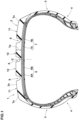
- FIG. 1 is a tire meridian cross-sectional view of a pneumatic tire 1 for passenger cars as an embodiment of the present invention under a standard state of the tire 1.
- the standard state is such that the tire is mounted on a standard rim, and inflated to a standard pressure, but loaded with no tire load.
- the standard state means a standard usage state of the tire according to the purpose of use of the tire, which is not mounted on the vehicle and loaded with no tire load.
- the standard wheel rim is a wheel rim officially approved or recommended for the tire by the standardization organization, i.e. JATMA (Japan and Asia), T&RA (North America), ETRTO (Europe), TRAA (Australia), STRO (Scandinavia), ALAPA (Latin America), ITTAC (India) and the like which are effective in the area where the tire is manufactured, sold or used.
- the standard pressure and the under-mentioned standard tire load are the maximum air pressure and the maximum tire load for the tire specified by the same organization in the Air-pressure/Maximum-load Table or similar list.
- the standard pressure is the "maximum air pressure” in JATMA, the “Inflation Pressure” in ETRTO, the maximum pressure given in the "Tire Load Limits at Various Cold Inflation Pressures” table in TRA or the like.
- the under-mentioned tread edges Te are the axial outermost edges of the ground contacting patch of the tire which occurs when the tire under its standard state is loaded with the standard tire load and placed on a horizontal flat surface at a camber angle of zero degree.
- the pneumatic tire 1 comprises
- the carcass 6 is composed of two carcass plies 6A and 6B.
- Each of the carcass plies 6A and 6B is composed of rubberized cords arranged radially at an angle of 75 to 90 degrees with respect to the tire circumferential direction.
- the carcass cord is made of organic fibers.
- the tread reinforcing cord layer 7 is composed of two plies 7A and 7B of reinforcing cords.
- each of the reinforcing plies 7A and 7B is composed of parallel reinforcing cords arranged at an angle of 10 to 45 degrees with respect to the tire circumferential direction and rubberized with topping rubber.
- the reinforcing cords organic fiber cords or steel cords may be appropriately used.
- the tread portion 2 is provided with circumferential grooves 8 extending continuously in the tire circumferential direction to axially divide a first land portion 11 and a second land portion 12 which is located on the tire equator C side of the first land portion 11.
- the tread portion 2 is provided with three circumferential grooves 8, and thereby, the tread portion 2 is axially divided into four land portions: a pair of axially outer first land portions 11 and a pair of axially inner second land portions 12 therebetween.
- the cap tread rubber layer 16 is radially outermost, and forms the ground contacting surface 2s.
- the intermediate tread rubber layer 17 is disposed on the radially inside of the cap tread rubber layer 16.
- the tread rubber disposed on the radially outside of the tread reinforcing cord layer 7 is composed of three rubber layers: the cap tread rubber layer 16, the intermediate tread rubber layer 17 and the base tread rubber layer 20.
- the present invention is however, not limited to such three layer structure.
- the shortest distance L2 from the ground contacting surface 12s of the second land portion 12 to the radially outer surface of the intermediate tread rubber layer 17 of the second land portion 12 is set to be smaller than the shortest distance L1 from the ground contacting surface 11s of the first land portion 11 to the radially outer surface of the intermediate tread rubber layer 17 of the first land portion 11.
- the intermediate tread rubber layer 17 having excellent frictional force on wet road surfaces is exposed, and thereby, the deterioration of the wet performance due to the wear of the tread portion 2 can be compensated for by exposing the intermediate tread rubber layer 17, and good wet performance is stably exhibited.
- the intermediate tread rubber layer 17 of the second land portion 12 is exposed, and after a while, the intermediate tread rubber layer 17 of the first land portion 11 is exposed. Therefore, the change in wet performance, namely, improvement due to the exposure of the intermediate tread rubber layer 17 becomes gradual.
- tread grooves are gradually decreased in depth and volume, which affects the wet performance. But, the deterioration of the wet performance due to the gradual decrease in the groove depth and volume is compensated by the gradual exposure of the intermediate tread rubber layer 17.
- the loss tangent (tan ⁇ 1) of the cap tread rubber layer 16 is preferably set to be not less than 0.13, more preferably not less than 0.15, still more preferably not less than 0.18, but not more than 0.30, more preferably not more than 0.25, still more preferably not more than 0.22.
- the loss tangent (tan ⁇ 2) of the intermediate tread rubber layer 17 is set to be not less than 0.20, more preferably not less than 0.25, still more preferably not less than 0.28, but not more than 0.40, more preferably not more than 0.35, still more preferably not more than 0.32 in order to improve steering stability and wet performance when the tread portion 2 is worn.
- Each of the cap tread rubber layer 16 and the intermediate tread rubber layer 17 has a substantially constant thickness except for the vicinity of each circumferential groove 8. Thereby, their separation at the boundary of these rubber layers can be suppressed.
- the above-said vicinity of the circumferential groove 8 may include a range of not more than 50% of the groove width of the circumferential groove 8 at the groove top, from each of the groove walls toward the both sides of the circumferential groove 8.
- substantially constant thickness means that the difference between the maximum value and the minimum value of the thickness is not more than 5% of the maximum value.
- the distance L1 in the first land portion 11 is preferably 35% to 55%, more preferably 40 to 50% of the tread thickness t1 measured in the first land portion 11 from the radially outer surface of the tread reinforcing cord layer 7 to the radially outer surface of the tread portion 2.
- the distance L1 is preferably not less than 150%, more preferably not less than 180%, but preferably not more than 250%, more preferably not more than 220% of the distance L2. Thereby, the wet performance is more stably exhibited.
- the thickness t3 of the intermediate tread rubber layer 17 is preferably set in a range from 30% to 50% of the above-said tread thickness t1.
- the thickness t4 of the intermediate tread rubber layer 17 is preferably set in a range from 50% to 70% of the tread thickness t2.
- the tread portion 2 includes the base tread rubber layer 20 disposed on the radially inside of the intermediate tread rubber layer 17.
- the loss tangent (tan ⁇ b) of the base tread rubber layer 20 is smaller than the loss tangent (tan ⁇ 1) of the cap tread rubber layer 16. Specifically, the loss tangent (tan ⁇ b) is less than 0.13.
- Such base tread rubber layer 20 helps to suppress excessive heat generation of the tread portion 2.
- the thickness of the base tread rubber layer 20 is preferably set in a range from 10% to 30% of the tread thickness from the radially outer surface of the tread reinforcing cord layer 7 to the radially outer surface of the tread portion 2.
- the boundary 18 between the cap tread rubber layer 16 and the intermediate tread rubber layer 17 extends parallel to the ground contacting surface, except for the vicinity of each circumferential groove 8.
- FIG. 3 shows another example of the first land portion 11 and the second land portion 12, wherein the boundary 18 (except for portions in the vicinities of the circumferential grooves 8) does not extend parallel to the ground contacting surface 2s of the tread portion 2.
- the boundary 18 comprises a radially outwardly protruding portion 23, and the radial distance from the radially outer surface of the tread portion 2 to the protruding portion 23 of the boundary 18 is increased toward both sides in the tire axial direction from the radially outwardly most protruding position.
- the intermediate tread rubber layer 17 is gradually increased in occupied area in the tread surface, therefore, the wet performance can be more stably exhibited.
- the radius of curvature R2 of the boundary 18 in the second land portion 12 is smaller than the radius of curvature R1 of the boundary 18 in the first land portion 11. As a result, it is possible to increase the amount of wear required for the intermediate tread rubber layer 17 to be completely exposed in the second land portion 12, while suppressing the separation of the rubber layers at the boundary 18.
- FIG. 4 shows still another example of the first land portion 11 and the second land portion 12, wherein the boundary 18 is undulated. Specifically, in the tire meridian cross section, the boundary 18 extends in the tire axial direction, while oscillating in the tire radial direction, thus, showing a wavy shape.
- the intermediate tread rubber layer 17 is gradually increased in occupied area in the tread surface, as the wear of the tread portion progresses, and thereby, the wet performance can be more stably exhibited.
- pneumatic tires of size 235/65R16C were experimentally manufactured as test tires including working example Ex.1, and comparative examples Ref.1 and Ref.2.
- the loss tangent (tan ⁇ 1) of the cap tread rubber layer was larger than the loss tangent (tan ⁇ 2) of the intermediate tread rubber layer, and the distance L1 was equal to the distance L2.
- the loss tangent (tan ⁇ 1) of the cap tread rubber layer was smaller than the loss tangent (tan ⁇ 2) of the intermediate tread rubber layer, and the distance L1 was equal to the distance L2.
- the tread thickness t1 in the first land portion and the tread thickness t2 in the second land portion were substantially the same in each test tire and also for all test tires.
- the braking distance was measured by applying full brake when the test vehicle was running at a speed of 65 km/h on an asphalt road surface of a tire test course, covered with 1.5 mm depth water.
- FIG. 5 The results are shown in FIG. 5 as a graph, wherein the horizontal axis is the amount of wear (AW) of the tread portion, and the vertical axis is the wet braking distance (WBD). Needless to say, the smaller wet braking distance is better.
- AW amount of wear
- WBD wet braking distance
- the graph G1 shows the WBD-AW relationship of the comparative example Ref.1
- the graph G2 shows the WBD-AW relationship of the comparative example Ref.2
- the graph G3 shows the WBD-AW relationship of the working example Ex.1.
- the wet braking distance (WBD) was small in the initial stage of tread wear. However, when the tread portion was worn and the intermediate tread rubber layer having the smaller loss tangent was exposed, the wet braking distance (WBD) changed abruptly and increased. Then, the wet braking distance (WBD) was gradually increased as the amount of wear (AW) increased.
- the wet braking distance (WBD) was changed linearly with respect to the change in the amount of wear (AW) of the tread portion without the abrupt changes as in the comparative examples.
- the tire according to the present invention can stably exhibit good wet performance until the end of the tread wear life.
- the present invention is as follows:
Landscapes
- Engineering & Computer Science (AREA)
- Mechanical Engineering (AREA)
- Tires In General (AREA)
Abstract
Description
- The present invention relates to a tire.
-
Patent Document 1 below discloses a pneumatic tire, wherein the tread portion thereof comprises a first cap rubber layer and a second cap rubber layer which have loss tangents specifically defined in order to improve rolling resistance and wet braking performance of the tire. - Patent Document 1:
Japanese Patent Application Publication No. 2018-002008 - On the other hand, there is a demand for a tire which can exhibit good wet performance from the initial stage to the final stage of the wear life of the tread portion. But, in the case of a tire of which tread portion comprises rubber layers having different loss tangents such as the pneumatic tire disclosed in
Patent Document 1, there is a problem such that the wet performance tends to change suddenly in the middle stage of the wear life of the tread portion. - The present invention was made in view of the above circumstances, and a primary objective of the present invention is to provide a tire which can stably exhibit good wet performance from the initial stage to the final stage of the wear life of the tread portion.
- According to the present invention, a tire comprises a tread portion provided with circumferential grooves which extend continuously in the tire circumferential direction to divide a first land portion and a second land portion which is located axially inside the first land portion,
each of the first land portion and the second land portion comprises a radially outermost cap tread rubber layer forming a ground contacting surface, and an intermediate tread rubber layer arranged on the radially inside of the cap tread rubber layer,
wherein - the loss tangent δ2 of the intermediate tread rubber layer is larger than the loss tangent δ1 of the cap tread rubber layer, and
- the shortest distance L2 from the ground contacting surface of the second land portion to the radially outer surface of the intermediate tread rubber layer of the second land portion is less than the shortest distance L1 from the ground contacting surface of the first land portion to the radially outer surface of the intermediate tread rubber layer of the first land portion.
- In the tire according to the present invention, therefore, owing to the different loss tangents δ1 and δ2 and the different distances L1 and L2 to the respective intermediate tread rubber layers, good wet performance is stably exhibited from the initial stage to the final stage of the tread wear life.
-
-
FIG. 1 is a meridian cross-sectional view of a tire as an embodiment of the present invention. -
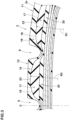
FIG. 2 is a meridian cross-sectional view enlargedly showing the second land portion and a part of the first land portion ofFIG. 1 . -
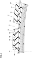
FIG. 3 is a meridian cross-sectional view enlargedly showing another example of the first land portion and the second land portion. -
FIG. 4 is a meridian cross-sectional view enlargedly showing still another example of the first land portion and the second land portion. -
FIG. 5 is a graph showing a relationship between the wear amount (AW) of the tread portion and the wet braking distance (WBD) of each test tire. - The present invention can be applied to pneumatic tires for various vehicles. e.g. passenger cars, heavy vehicles such as trucks and buses, motorcycles and the like, but, in particular, suitably applied to passenger car tires.
- Taking a pneumatic tire for passenger cars as an example, embodiments of the present invention will be described in detail in conjunction with accompanying drawings.
-
FIG. 1 is a tire meridian cross-sectional view of apneumatic tire 1 for passenger cars as an embodiment of the present invention under a standard state of thetire 1. - In this application including specification and claims, various dimensions, positions and the like of the tire refer to those under the standard state unless otherwise noted.
- In the case of a pneumatic tire for which various specifications are set by a standardization organization, the standard state is such that the tire is mounted on a standard rim, and inflated to a standard pressure, but loaded with no tire load.
- In the case of a tire for which various specifications are not yet set, the standard state means a standard usage state of the tire according to the purpose of use of the tire, which is not mounted on the vehicle and loaded with no tire load. The standard wheel rim is a wheel rim officially approved or recommended for the tire by the standardization organization, i.e. JATMA (Japan and Asia), T&RA (North America), ETRTO (Europe), TRAA (Australia), STRO (Scandinavia), ALAPA (Latin America), ITTAC (India) and the like which are effective in the area where the tire is manufactured, sold or used.
- The standard pressure and the under-mentioned standard tire load are the maximum air pressure and the maximum tire load for the tire specified by the same organization in the Air-pressure/Maximum-load Table or similar list.
- For example, the standard pressure is the "maximum air pressure" in JATMA, the "Inflation Pressure" in ETRTO, the maximum pressure given in the "Tire Load Limits at Various Cold Inflation Pressures" table in TRA or the like.
- The standard tire load is the "maximum load capacity" in JATMA, the "Load Capacity" in ETRTO, the maximum value given in the above-mentioned table in TRA or the like.
- The under-mentioned tread edges Te are the axial outermost edges of the ground contacting patch of the tire which occurs when the tire under its standard state is loaded with the standard tire load and placed on a horizontal flat surface at a camber angle of zero degree.
- The
pneumatic tire 1 comprises - a
tread portion 2 whose radially outer surface defines the tread or theground contacting surface 2s of the tire, - a pair of axially spaced
bead portions 4 mounted on rim seats of a wheel rim, - a pair of
sidewall portions 3 extending between the tread edges Te and thebead portions 4, - a
carcass 6 extending between thebead portions 4 through thetread portion 2 and thesidewall portions 3, and a tread reinforcingcord layer 7 disposed radially outside the carcass in the tread portion. - In the present embodiment, the
carcass 6 is composed of twocarcass plies carcass plies - In the present embodiment, the tread reinforcing
cord layer 7 is composed of twoplies plies - The
tread portion 2 is provided withcircumferential grooves 8 extending continuously in the tire circumferential direction to axially divide afirst land portion 11 and asecond land portion 12 which is located on the tire equator C side of thefirst land portion 11. - In the present embodiment, the
tread portion 2 is provided with threecircumferential grooves 8, and thereby, thetread portion 2 is axially divided into four land portions: a pair of axially outerfirst land portions 11 and a pair of axially innersecond land portions 12 therebetween. - The present invention is however, not limited to such a four land portion arrangement.
- As shown in
FIG. 2 , each of thefirst land portions 11 and thesecond land portions 12 comprises a captread rubber layer 16, an intermediatetread rubber layer 17 and a basetread rubber layer 20. - The cap
tread rubber layer 16 is radially outermost, and forms theground contacting surface 2s. - The intermediate
tread rubber layer 17 is disposed on the radially inside of the captread rubber layer 16. - The base
tread rubber layer 20 is disposed on the radially inside of the intermediatetread rubber layer 17. - In the present embodiment, the tread rubber disposed on the radially outside of the tread reinforcing
cord layer 7 is composed of three rubber layers: the captread rubber layer 16, the intermediatetread rubber layer 17 and the basetread rubber layer 20. The present invention is however, not limited to such three layer structure. - Incidentally, in
FIG. 1 , the tread rubber is hatched as if a single rubber layer for simplification. - It has been known that, in general, rubber having a large loss tangent can exert a large frictional force on a wet road surface.
- However, in the present invention, the loss tangent (tan δ2) of the radially inner intermediate
tread rubber layer 17 is set to be larger than the loss tangent (tan δ1) of the radially outermost captread rubber layer 16. - Here, the loss tangent (tan δ) is measured according to Japanese Industrial Standard (JIS) K6394, using a dynamic mechanical characteristic analyzer (GABO EPLEXOR Series), under the following conditions: Initial strain 5%, Dynamic strain amplitude +/-1%, Frequency 10Hz, Temperature 30 degrees C, Deformation mode Tensile mode.
- According to the present invention, the shortest distance L2 from the
ground contacting surface 12s of thesecond land portion 12 to the radially outer surface of the intermediatetread rubber layer 17 of thesecond land portion 12 is set to be smaller than
the shortest distance L1 from theground contacting surface 11s of thefirst land portion 11 to the radially outer surface of the intermediatetread rubber layer 17 of thefirst land portion 11. Thereby, thetire 1 according to the present invention can stably exhibit good wet performance from the initial stage to the final stage of the wear life of thetread portion 2 for the following reason. - Overall, as the wear of the
tread portion 2 progresses, the intermediatetread rubber layer 17 having excellent frictional force on wet road surfaces is exposed, and thereby, the deterioration of the wet performance due to the wear of thetread portion 2 can be compensated for by exposing the intermediatetread rubber layer 17, and good wet performance is stably exhibited. - If the intermediate
tread rubber layer 17 is exposed in the entire area or a wide area of the tread surface of theworn tread portion 2 at about the same time, then the change in wet performance before and after the intermediatetread rubber layer 17 is exposed becomes large. This is not desirable. - According to the present invention, since the distance L2 in the
second land portion 12 is smaller than the distance L1 in thefirst land portion 11, the intermediatetread rubber layer 17 of thesecond land portion 12 is exposed, and after a while, the intermediatetread rubber layer 17 of thefirst land portion 11 is exposed. Therefore, the change in wet performance, namely, improvement due to the exposure of the intermediatetread rubber layer 17 becomes gradual. - On the other hand, as the wear progresses, tread grooves are gradually decreased in depth and volume, which affects the wet performance. But, the deterioration of the wet performance due to the gradual decrease in the groove depth and volume is compensated by the gradual exposure of the intermediate
tread rubber layer 17. - For this reason, the
tire 1 according to the present invention can exhibit good wet performance stably from the initial stage to the final stage of the wear life of thetread portion 2. - The loss tangent (tan δ1) of the cap
tread rubber layer 16 is preferably set to be not less than 0.13, more preferably not less than 0.15, still more preferably not less than 0.18, but not more than 0.30, more preferably not more than 0.25, still more preferably not more than 0.22. - Such cap
tread rubber layer 16 can exhibit steering stability on dry road surfaces (hereinafter, simply referred to as "steering stability") and wet performance in a well-balanced manner in the initial stage of the tread wear life. - It is preferable that the loss tangent (tan δ2) of the intermediate
tread rubber layer 17 is set to be not less than 0.20, more preferably not less than 0.25, still more preferably not less than 0.28, but not more than 0.40, more preferably not more than 0.35, still more preferably not more than 0.32 in order to improve steering stability and wet performance when thetread portion 2 is worn. - If the difference between the loss tangent (tan δ1) and the loss tangent (tan δ2) is small, it is difficult to derive the above-mentioned effect. If the difference is large, then the separation failure is likely to occur at the boundary between the cap
tread rubber layer 16 and the intermediatetread rubber layer 17. - From such a viewpoint, it is preferable that the loss tangent (tan δ2) is 1.2 to 2.5 times, more preferably 1.5 to 2.0 times the loss tangent (tan δ1).
- Each of the cap
tread rubber layer 16 and the intermediatetread rubber layer 17 has a substantially constant thickness except for the vicinity of eachcircumferential groove 8. Thereby, their separation at the boundary of these rubber layers can be suppressed. - The above-said vicinity of the
circumferential groove 8 may include a range of not more than 50% of the groove width of thecircumferential groove 8 at the groove top, from each of the groove walls toward the both sides of thecircumferential groove 8. - The expression "substantially constant thickness" means that the difference between the maximum value and the minimum value of the thickness is not more than 5% of the maximum value.
- The distance L1 in the
first land portion 11 is preferably 35% to 55%, more preferably 40 to 50% of the tread thickness t1 measured in thefirst land portion 11 from the radially outer surface of the tread reinforcingcord layer 7 to the radially outer surface of thetread portion 2. - The distance L2 of the
second land portion 12 is preferably 10% to 30%, more preferably 15% to 25% of the tread thickness t2 measured in thesecond land portion 12 from the radially outer surface of the tread reinforcingcord layer 7 to the radially outer surface of thetread portion 2. - Further, the distance L1 is preferably not less than 150%, more preferably not less than 180%, but preferably not more than 250%, more preferably not more than 220% of the distance L2. Thereby, the wet performance is more stably exhibited.
- In the
first land portion 11, the thickness t3 of the intermediatetread rubber layer 17 is preferably set in a range from 30% to 50% of the above-said tread thickness t1. - In the
second land portion 12, the thickness t4 of the intermediatetread rubber layer 17 is preferably set in a range from 50% to 70% of the tread thickness t2. - The present invention is however, not limited to such thickness ranges.
- The
tread portion 2 includes the basetread rubber layer 20 disposed on the radially inside of the intermediatetread rubber layer 17. - The loss tangent (tan δb) of the base
tread rubber layer 20 is smaller than the loss tangent (tan δ1) of the captread rubber layer 16. Specifically, the loss tangent (tan δb) is less than 0.13. Such basetread rubber layer 20 helps to suppress excessive heat generation of thetread portion 2. - The base tread rubber layer has a substantially constant thickness except for the vicinity of the
circumferential groove 8. The meaning of the expression "substantially constant thickness" is as explained above. - The thickness of the base
tread rubber layer 20 is preferably set in a range from 10% to 30% of the tread thickness from the radially outer surface of the tread reinforcingcord layer 7 to the radially outer surface of thetread portion 2. - In the present embodiment, the
boundary 18 between the captread rubber layer 16 and the intermediatetread rubber layer 17 extends parallel to the ground contacting surface, except for the vicinity of eachcircumferential groove 8. - The present invention is however, not limited to such example. For example,
FIG. 3 shows another example of thefirst land portion 11 and thesecond land portion 12, wherein the boundary 18 (except for portions in the vicinities of the circumferential grooves 8) does not extend parallel to theground contacting surface 2s of thetread portion 2. - More specifically, in each of the
first land portion 11 and thesecond land portion 12, theboundary 18 comprises a radially outwardly protrudingportion 23, and
the radial distance from the radially outer surface of thetread portion 2 to the protrudingportion 23 of theboundary 18 is increased toward both sides in the tire axial direction from the radially outwardly most protruding position. - Accordingly, as the wear of the tread portion progresses, the intermediate
tread rubber layer 17 is gradually increased in occupied area in the tread surface, therefore, the wet performance can be more stably exhibited. - It is preferable that the radius of curvature R2 of the
boundary 18 in thesecond land portion 12 is smaller than the radius of curvature R1 of theboundary 18 in thefirst land portion 11. As a result, it is possible to increase the amount of wear required for the intermediatetread rubber layer 17 to be completely exposed in thesecond land portion 12, while suppressing the separation of the rubber layers at theboundary 18. -
FIG. 4 shows still another example of thefirst land portion 11 and thesecond land portion 12, wherein theboundary 18 is undulated. Specifically, in the tire meridian cross section, theboundary 18 extends in the tire axial direction, while oscillating in the tire radial direction, thus, showing a wavy shape. - In this example, too, the intermediate
tread rubber layer 17 is gradually increased in occupied area in the tread surface, as the wear of the tread portion progresses, and thereby, the wet performance can be more stably exhibited. - In addition, the substantial length of the
boundary 18 is increased, which helps to suppress the separation between the rubber layers at theboundary 18. - As shown in
FIG. 4 , the amplitude A2 in the tire radial direction of theboundary 18 in thesecond land portion 12 is preferably larger than the amplitude A1 in the tire radial direction of theboundary 18 in thefirst land portion 11. Thereby, it is possible to increase the amount of wear required for the intermediatetread rubber layer 17 to be completely exposed in thesecond land portion 12. - while detailed description has been made of preferable embodiments of the present invention, the present invention can be embodied in various forms without being limited to the illustrated embodiments.
- Based on the structure shown in
FIG. 1 , pneumatic tires of size 235/65R16C were experimentally manufactured as test tires including working example Ex.1, and comparative examples Ref.1 and Ref.2. - Specifications of the test tires are shown in Table 1.
- In the comparative example Ref.1, the loss tangent (tan δ1) of the cap tread rubber layer was larger than the loss tangent (tan δ2) of the intermediate tread rubber layer, and the distance L1 was equal to the distance L2.
- In the comparative example Ref.2, the loss tangent (tan δ1) of the cap tread rubber layer was smaller than the loss tangent (tan δ2) of the intermediate tread rubber layer, and the distance L1 was equal to the distance L2.
- The tread thickness t1 in the first land portion and the tread thickness t2 in the second land portion were substantially the same in each test tire and also for all test tires.
- All test tires had substantially the same structures except for the loss tangents, distances and thicknesses shown in Table 1.
Table 1 Ti re Ref. 1 Ref.2 Ex. 1 cap tread rubber layer tan δ1 0.35 0.20 0.20 intermediate tread rubber layer tan δ2 0.20 0.35 0.35 distance L1 / tread thickness t1 (%) 40 40 40 distance L2 / tread thickness t2 (%) 40 40 20 - For each test tire, the relationship between the amount of wear (AW) of the tread portion and the wet braking distance (WBD) was investigated.
- The test tire was mounted on a standard rim (size 16x7.0J) and attached to a test vehicle (3000cc rear-wheel-drive commercial vehicle), and the wet braking distance (WBD) was measured using the test vehicle.
- The braking distance was measured by applying full brake when the test vehicle was running at a speed of 65 km/h on an asphalt road surface of a tire test course, covered with 1.5 mm depth water.
- Such measurement was carried out many times from a state in which the amount of wear = 0% (that is, a new tire state) to a state in which the amount of wear = 100% (that is, the tread wear reached to the wear indicator).
- The results are shown in
FIG. 5 as a graph, wherein the horizontal axis is the amount of wear (AW) of the tread portion, and the vertical axis is the wet braking distance (WBD). Needless to say, the smaller wet braking distance is better. - In
FIG. 5 , the graph G1 shows the WBD-AW relationship of the comparative example Ref.1, the graph G2 shows the WBD-AW relationship of the comparative example Ref.2 and the graph G3 shows the WBD-AW relationship of the working example Ex.1. - As shown in
FIG. 5 , in each test tire, as the amount of wear (AW) of the tread portion increased, the drainage property of the circumferential grooves was decreased and the wet braking distance (WBD) was increased. - In the comparative example Ref.1, the wet braking distance (WBD) was small in the initial stage of tread wear. However, when the tread portion was worn and the intermediate tread rubber layer having the smaller loss tangent was exposed, the wet braking distance (WBD) changed abruptly and increased. Then, the wet braking distance (WBD) was gradually increased as the amount of wear (AW) increased.
- In the comparative example Ref.2, the large abrupt change of the wet braking distance was suppressed as compared with the comparative example Ref.1, but a smaller abrupt change still existed because the intermediate tread rubber layer appeared in the entire tread surface within a short period of time.
- In the working example Ex.1, the wet braking distance (WBD) was changed linearly with respect to the change in the amount of wear (AW) of the tread portion without the abrupt changes as in the comparative examples.
- Thus, it was confirmed that the tire according to the present invention can stably exhibit good wet performance until the end of the tread wear life.
- The present invention is as follows:
- Invention 1: A tire comprising a tread portion provided with circumferential grooves which extend continuously in the tire circumferential direction to divide a first land portion and a second land portion which is located axially inside the first land portion,
wherein- each of the first land portion and the second land portion comprises a radially outermost cap tread rubber layer forming a ground contacting surface, and an intermediate tread rubber layer arranged on the radially inside of the cap tread rubber layer;
- the loss tangent δ2 of the intermediate tread rubber layer is larger than the loss tangent δ1 of the cap tread rubber layer; and
- the shortest distance L2 from the ground contacting surface of the second land portion to the radially outer surface of the intermediate tread rubber layer of the second land portion is less than the shortest distance L1 from the ground contacting surface of the first land portion to the radially outer surface of the intermediate tread rubber layer of the first land portion.
- Invention 2: The tire according to
Invention 1, wherein the tread portion comprises a base tread rubber layer disposed on the radially inside of the intermediate tread rubber layer, and the loss tangent δb of the base tread rubber layer is smaller than the loss tangent δ1 of the cap tread rubber layer. - Present Invention 3: The tire according to
Present Invention 2, wherein the loss tangent δb of the base tread rubber layer is less than 0.13. - Invention 4: The tire according to
Invention - Invention 5: The tire according to any one of
Inventions 2 to 4, wherein the tread portion is provided with a tread reinforcing cord layer composed of cords coated with topping rubber and disposed radially inside the base tread rubber layer, and the thickness of the base tread rubber layer is 10% to 30% of the tread thickness measured from the radially outer surface of the tread portion to the radially outer surface of the tread reinforcing cord layer. - Invention 6: The tire according to any one of
Inventions 1 to 5, wherein the loss tangent δ1 of the cap tread rubber layer is 0.13 to 0.30. - Invention 7: The tire according to any one of
Inventions 1 to 6, wherein the loss tangent δ2 of the intermediate tread rubber layer is 0.20 to 0.40. - Invention 8: The tire according to any one of
Inventions 1 to 7, wherein the distance L1 is 150% to 250% of the distance L2. -
- 2 tread portion
- 8 circumferential groove
- 11 first land portion
- 12 second land portion
- 16 cap tread rubber layer
- 17 intermediate tread rubber layer
- C tire equator
Claims (8)
- A tire comprising a tread portion provided with circumferential grooves which extend continuously in the tire circumferential direction to divide a first land portion and a second land portion which is located axially inside the first land portion,
whereineach of the first land portion and the second land portion comprises a radially outermost cap tread rubber layer forming a ground contacting surface, and an intermediate tread rubber layer arranged on the radially inside of the cap tread rubber layer;the loss tangent δ2 of the intermediate tread rubber layer is larger than the loss tangent δ1 of the cap tread rubber layer; andthe shortest distance L2 from the ground contacting surface of the second land portion to the radially outer surface of the intermediate tread rubber layer of the second land portion is less than the shortest distance L1 from the ground contacting surface of the first land portion to the radially outer surface of the intermediate tread rubber layer of the first land portion. - The tire according to claim 1, whereinthe tread portion comprises a base tread rubber layer disposed on the radially inside of the intermediate tread rubber layer, andthe loss tangent δb of the base tread rubber layer is smaller than the loss tangent δ1 of the cap tread rubber layer.
- The tire according to claim 2, wherein
the loss tangent δb of the base tread rubber layer is less than 0.13. - The tire according to claim 2 or 3, wherein
the base tread rubber layer extends in the tire axial direction with a substantially constant thickness. - The tire according to any one of claims 2 to 4, whereinthe tread portion is provided with a tread reinforcing cord layer composed of cords coated with topping rubber and disposed radially inside the base tread rubber layer, andthe thickness of the base tread rubber layer is 10% to 30% of the tread thickness measured from the radially outer surface of the tread portion to the radially outer surface of the tread reinforcing cord layer.
- The tire according to any one of claims 1 to 5, wherein
the loss tangent δ1 of the cap tread rubber layer is 0.13 to 0.30. - The tire according to any one of claims 1 to 6, wherein
the loss tangent δ2 of the intermediate tread rubber layer is 0.20 to 0.40. - The tire according to any one of claims 1 to 7, wherein
the shortest distance L1 is 150% to 250% of the shortest distance L2.
Applications Claiming Priority (1)
| Application Number | Priority Date | Filing Date | Title |
|---|---|---|---|
| JP2021178906A JP7715009B2 (en) | 2021-11-01 | 2021-11-01 | tire |
Publications (2)
| Publication Number | Publication Date |
|---|---|
| EP4173845A1 true EP4173845A1 (en) | 2023-05-03 |
| EP4173845B1 EP4173845B1 (en) | 2024-09-18 |
Family
ID=83059147
Family Applications (1)
| Application Number | Title | Priority Date | Filing Date |
|---|---|---|---|
| EP22191896.4A Active EP4173845B1 (en) | 2021-11-01 | 2022-08-24 | Tire |
Country Status (4)
| Country | Link |
|---|---|
| US (1) | US20230139129A1 (en) |
| EP (1) | EP4173845B1 (en) |
| JP (1) | JP7715009B2 (en) |
| CN (1) | CN116061606A (en) |
Cited By (1)
| Publication number | Priority date | Publication date | Assignee | Title |
|---|---|---|---|---|
| EP4059740B1 (en) * | 2021-03-17 | 2025-08-06 | Sumitomo Rubber Industries, Ltd. | Tire |
Citations (3)
| Publication number | Priority date | Publication date | Assignee | Title |
|---|---|---|---|---|
| JP2015199465A (en) * | 2014-04-10 | 2015-11-12 | 住友ゴム工業株式会社 | Pneumatic tire |
| EP2418103B1 (en) * | 2009-05-15 | 2016-07-27 | Sumitomo Rubber Industries, Ltd. | Pneumatic tire |
| JP2018002008A (en) | 2016-07-05 | 2018-01-11 | 住友ゴム工業株式会社 | Pneumatic tire |
Family Cites Families (8)
| Publication number | Priority date | Publication date | Assignee | Title |
|---|---|---|---|---|
| JP3559118B2 (en) * | 1995-11-29 | 2004-08-25 | 株式会社ブリヂストン | Pneumatic radial tire |
| JP2006213193A (en) * | 2005-02-04 | 2006-08-17 | Sumitomo Rubber Ind Ltd | Pneumatic radial tire |
| JP2008279800A (en) | 2007-05-08 | 2008-11-20 | Bridgestone Corp | Pneumatic tire and its manufacturing method |
| JP5957405B2 (en) | 2013-03-19 | 2016-07-27 | 住友ゴム工業株式会社 | Pneumatic tire |
| CN106232389B (en) * | 2014-05-08 | 2018-07-10 | 普利司通股份有限公司 | tire |
| EP3260305B1 (en) * | 2016-06-22 | 2019-03-13 | Sumitomo Rubber Industries, Ltd. | Pneumatic tire |
| CN111108006B (en) * | 2017-09-28 | 2022-02-25 | 米其林集团总公司 | Truck tires with tread designs to reduce abnormal wear |
| JP6863504B1 (en) | 2020-04-24 | 2021-04-21 | 住友ゴム工業株式会社 | tire |
-
2021
- 2021-11-01 JP JP2021178906A patent/JP7715009B2/en active Active
-
2022
- 2022-08-24 EP EP22191896.4A patent/EP4173845B1/en active Active
- 2022-10-10 CN CN202211232463.1A patent/CN116061606A/en active Pending
- 2022-10-19 US US17/968,911 patent/US20230139129A1/en not_active Abandoned
Patent Citations (3)
| Publication number | Priority date | Publication date | Assignee | Title |
|---|---|---|---|---|
| EP2418103B1 (en) * | 2009-05-15 | 2016-07-27 | Sumitomo Rubber Industries, Ltd. | Pneumatic tire |
| JP2015199465A (en) * | 2014-04-10 | 2015-11-12 | 住友ゴム工業株式会社 | Pneumatic tire |
| JP2018002008A (en) | 2016-07-05 | 2018-01-11 | 住友ゴム工業株式会社 | Pneumatic tire |
Cited By (1)
| Publication number | Priority date | Publication date | Assignee | Title |
|---|---|---|---|---|
| EP4059740B1 (en) * | 2021-03-17 | 2025-08-06 | Sumitomo Rubber Industries, Ltd. | Tire |
Also Published As
| Publication number | Publication date |
|---|---|
| CN116061606A (en) | 2023-05-05 |
| EP4173845B1 (en) | 2024-09-18 |
| JP7715009B2 (en) | 2025-07-30 |
| US20230139129A1 (en) | 2023-05-04 |
| JP2023067545A (en) | 2023-05-16 |
Similar Documents
| Publication | Publication Date | Title |
|---|---|---|
| US11331963B2 (en) | Run-flat tire | |
| EP2732983B1 (en) | Pneumatic tire | |
| US11794529B2 (en) | Run-flat tire | |
| EP3332991B1 (en) | Pneumatic tire | |
| EP3501852A1 (en) | Tyre | |
| WO2014128966A1 (en) | Pneumatic tire | |
| US11458775B2 (en) | Pneumatic tyre, tyre mold and method for manufacturing pneumatic tyre using the same | |
| EP4173845B1 (en) | Tire | |
| JP7711476B2 (en) | tire | |
| US12187075B2 (en) | Tire | |
| EP2602125A1 (en) | Pneumatic tire | |
| EP3552846B1 (en) | Tyre | |
| US12097726B2 (en) | Tire | |
| EP4219193B1 (en) | Method of using a tyre | |
| EP4056385B1 (en) | Pneumatic tire | |
| JP2003146015A (en) | Pneumatic tire | |
| US12030344B2 (en) | Tire | |
| JP4687342B2 (en) | Pneumatic tire | |
| US20220072913A1 (en) | Tire having tread grooves and method for determining groove depths | |
| JP2007055479A (en) | Pneumatic tire | |
| EP4108475B1 (en) | Tyre | |
| EP4242013B1 (en) | Pneumatic tire | |
| EP4585429B1 (en) | Pneumatic tire | |
| US10940720B2 (en) | Tire for motorcycles | |
| JP2025162444A (en) | pneumatic tires |
Legal Events
| Date | Code | Title | Description |
|---|---|---|---|
| PUAI | Public reference made under article 153(3) epc to a published international application that has entered the european phase |
Free format text: ORIGINAL CODE: 0009012 |
|
| STAA | Information on the status of an ep patent application or granted ep patent |
Free format text: STATUS: THE APPLICATION HAS BEEN PUBLISHED |
|
| AK | Designated contracting states |
Kind code of ref document: A1 Designated state(s): AL AT BE BG CH CY CZ DE DK EE ES FI FR GB GR HR HU IE IS IT LI LT LU LV MC MK MT NL NO PL PT RO RS SE SI SK SM TR |
|
| STAA | Information on the status of an ep patent application or granted ep patent |
Free format text: STATUS: REQUEST FOR EXAMINATION WAS MADE |
|
| 17P | Request for examination filed |
Effective date: 20230613 |
|
| RBV | Designated contracting states (corrected) |
Designated state(s): AL AT BE BG CH CY CZ DE DK EE ES FI FR GB GR HR HU IE IS IT LI LT LU LV MC MK MT NL NO PL PT RO RS SE SI SK SM TR |
|
| P01 | Opt-out of the competence of the unified patent court (upc) registered |
Effective date: 20240327 |
|
| GRAP | Despatch of communication of intention to grant a patent |
Free format text: ORIGINAL CODE: EPIDOSNIGR1 |
|
| STAA | Information on the status of an ep patent application or granted ep patent |
Free format text: STATUS: GRANT OF PATENT IS INTENDED |
|
| GRAS | Grant fee paid |
Free format text: ORIGINAL CODE: EPIDOSNIGR3 |
|
| GRAA | (expected) grant |
Free format text: ORIGINAL CODE: 0009210 |
|
| STAA | Information on the status of an ep patent application or granted ep patent |
Free format text: STATUS: THE PATENT HAS BEEN GRANTED |
|
| INTG | Intention to grant announced |
Effective date: 20240718 |
|
| AK | Designated contracting states |
Kind code of ref document: B1 Designated state(s): AL AT BE BG CH CY CZ DE DK EE ES FI FR GB GR HR HU IE IS IT LI LT LU LV MC MK MT NL NO PL PT RO RS SE SI SK SM TR |
|
| REG | Reference to a national code |
Ref country code: GB Ref legal event code: FG4D |
|
| REG | Reference to a national code |
Ref country code: CH Ref legal event code: EP |
|
| REG | Reference to a national code |
Ref country code: IE Ref legal event code: FG4D |
|
| REG | Reference to a national code |
Ref country code: DE Ref legal event code: R096 Ref document number: 602022006170 Country of ref document: DE |
|
| REG | Reference to a national code |
Ref country code: LT Ref legal event code: MG9D |
|
| PG25 | Lapsed in a contracting state [announced via postgrant information from national office to epo] |
Ref country code: NO Free format text: LAPSE BECAUSE OF FAILURE TO SUBMIT A TRANSLATION OF THE DESCRIPTION OR TO PAY THE FEE WITHIN THE PRESCRIBED TIME-LIMIT Effective date: 20241218 |
|
| PG25 | Lapsed in a contracting state [announced via postgrant information from national office to epo] |
Ref country code: GR Free format text: LAPSE BECAUSE OF FAILURE TO SUBMIT A TRANSLATION OF THE DESCRIPTION OR TO PAY THE FEE WITHIN THE PRESCRIBED TIME-LIMIT Effective date: 20241219 Ref country code: FI Free format text: LAPSE BECAUSE OF FAILURE TO SUBMIT A TRANSLATION OF THE DESCRIPTION OR TO PAY THE FEE WITHIN THE PRESCRIBED TIME-LIMIT Effective date: 20240918 |
|
| PG25 | Lapsed in a contracting state [announced via postgrant information from national office to epo] |
Ref country code: BG Free format text: LAPSE BECAUSE OF FAILURE TO SUBMIT A TRANSLATION OF THE DESCRIPTION OR TO PAY THE FEE WITHIN THE PRESCRIBED TIME-LIMIT Effective date: 20240918 |
|
| PG25 | Lapsed in a contracting state [announced via postgrant information from national office to epo] |
Ref country code: LV Free format text: LAPSE BECAUSE OF FAILURE TO SUBMIT A TRANSLATION OF THE DESCRIPTION OR TO PAY THE FEE WITHIN THE PRESCRIBED TIME-LIMIT Effective date: 20240918 |
|
| PG25 | Lapsed in a contracting state [announced via postgrant information from national office to epo] |
Ref country code: HR Free format text: LAPSE BECAUSE OF FAILURE TO SUBMIT A TRANSLATION OF THE DESCRIPTION OR TO PAY THE FEE WITHIN THE PRESCRIBED TIME-LIMIT Effective date: 20240918 |
|
| REG | Reference to a national code |
Ref country code: NL Ref legal event code: MP Effective date: 20240918 |
|
| PG25 | Lapsed in a contracting state [announced via postgrant information from national office to epo] |
Ref country code: RS Free format text: LAPSE BECAUSE OF FAILURE TO SUBMIT A TRANSLATION OF THE DESCRIPTION OR TO PAY THE FEE WITHIN THE PRESCRIBED TIME-LIMIT Effective date: 20241218 |
|
| PG25 | Lapsed in a contracting state [announced via postgrant information from national office to epo] |
Ref country code: RS Free format text: LAPSE BECAUSE OF FAILURE TO SUBMIT A TRANSLATION OF THE DESCRIPTION OR TO PAY THE FEE WITHIN THE PRESCRIBED TIME-LIMIT Effective date: 20241218 Ref country code: NO Free format text: LAPSE BECAUSE OF FAILURE TO SUBMIT A TRANSLATION OF THE DESCRIPTION OR TO PAY THE FEE WITHIN THE PRESCRIBED TIME-LIMIT Effective date: 20241218 Ref country code: LV Free format text: LAPSE BECAUSE OF FAILURE TO SUBMIT A TRANSLATION OF THE DESCRIPTION OR TO PAY THE FEE WITHIN THE PRESCRIBED TIME-LIMIT Effective date: 20240918 Ref country code: HR Free format text: LAPSE BECAUSE OF FAILURE TO SUBMIT A TRANSLATION OF THE DESCRIPTION OR TO PAY THE FEE WITHIN THE PRESCRIBED TIME-LIMIT Effective date: 20240918 Ref country code: GR Free format text: LAPSE BECAUSE OF FAILURE TO SUBMIT A TRANSLATION OF THE DESCRIPTION OR TO PAY THE FEE WITHIN THE PRESCRIBED TIME-LIMIT Effective date: 20241219 Ref country code: FI Free format text: LAPSE BECAUSE OF FAILURE TO SUBMIT A TRANSLATION OF THE DESCRIPTION OR TO PAY THE FEE WITHIN THE PRESCRIBED TIME-LIMIT Effective date: 20240918 Ref country code: BG Free format text: LAPSE BECAUSE OF FAILURE TO SUBMIT A TRANSLATION OF THE DESCRIPTION OR TO PAY THE FEE WITHIN THE PRESCRIBED TIME-LIMIT Effective date: 20240918 |
|
| REG | Reference to a national code |
Ref country code: AT Ref legal event code: MK05 Ref document number: 1724392 Country of ref document: AT Kind code of ref document: T Effective date: 20240918 |
|
| PG25 | Lapsed in a contracting state [announced via postgrant information from national office to epo] |
Ref country code: NL Free format text: LAPSE BECAUSE OF FAILURE TO SUBMIT A TRANSLATION OF THE DESCRIPTION OR TO PAY THE FEE WITHIN THE PRESCRIBED TIME-LIMIT Effective date: 20240918 |
|
| PG25 | Lapsed in a contracting state [announced via postgrant information from national office to epo] |
Ref country code: IS Free format text: LAPSE BECAUSE OF FAILURE TO SUBMIT A TRANSLATION OF THE DESCRIPTION OR TO PAY THE FEE WITHIN THE PRESCRIBED TIME-LIMIT Effective date: 20250118 Ref country code: PT Free format text: LAPSE BECAUSE OF FAILURE TO SUBMIT A TRANSLATION OF THE DESCRIPTION OR TO PAY THE FEE WITHIN THE PRESCRIBED TIME-LIMIT Effective date: 20250120 |
|
| PG25 | Lapsed in a contracting state [announced via postgrant information from national office to epo] |
Ref country code: RO Free format text: LAPSE BECAUSE OF FAILURE TO SUBMIT A TRANSLATION OF THE DESCRIPTION OR TO PAY THE FEE WITHIN THE PRESCRIBED TIME-LIMIT Effective date: 20240918 Ref country code: SM Free format text: LAPSE BECAUSE OF FAILURE TO SUBMIT A TRANSLATION OF THE DESCRIPTION OR TO PAY THE FEE WITHIN THE PRESCRIBED TIME-LIMIT Effective date: 20240918 |
|
| PG25 | Lapsed in a contracting state [announced via postgrant information from national office to epo] |
Ref country code: ES Free format text: LAPSE BECAUSE OF FAILURE TO SUBMIT A TRANSLATION OF THE DESCRIPTION OR TO PAY THE FEE WITHIN THE PRESCRIBED TIME-LIMIT Effective date: 20240918 |
|
| PG25 | Lapsed in a contracting state [announced via postgrant information from national office to epo] |
Ref country code: EE Free format text: LAPSE BECAUSE OF FAILURE TO SUBMIT A TRANSLATION OF THE DESCRIPTION OR TO PAY THE FEE WITHIN THE PRESCRIBED TIME-LIMIT Effective date: 20240918 Ref country code: AT Free format text: LAPSE BECAUSE OF FAILURE TO SUBMIT A TRANSLATION OF THE DESCRIPTION OR TO PAY THE FEE WITHIN THE PRESCRIBED TIME-LIMIT Effective date: 20240918 |
|
| PG25 | Lapsed in a contracting state [announced via postgrant information from national office to epo] |
Ref country code: CZ Free format text: LAPSE BECAUSE OF FAILURE TO SUBMIT A TRANSLATION OF THE DESCRIPTION OR TO PAY THE FEE WITHIN THE PRESCRIBED TIME-LIMIT Effective date: 20240918 Ref country code: PL Free format text: LAPSE BECAUSE OF FAILURE TO SUBMIT A TRANSLATION OF THE DESCRIPTION OR TO PAY THE FEE WITHIN THE PRESCRIBED TIME-LIMIT Effective date: 20240918 |
|
| PG25 | Lapsed in a contracting state [announced via postgrant information from national office to epo] |
Ref country code: IT Free format text: LAPSE BECAUSE OF FAILURE TO SUBMIT A TRANSLATION OF THE DESCRIPTION OR TO PAY THE FEE WITHIN THE PRESCRIBED TIME-LIMIT Effective date: 20240918 Ref country code: SK Free format text: LAPSE BECAUSE OF FAILURE TO SUBMIT A TRANSLATION OF THE DESCRIPTION OR TO PAY THE FEE WITHIN THE PRESCRIBED TIME-LIMIT Effective date: 20240918 |
|
| REG | Reference to a national code |
Ref country code: DE Ref legal event code: R097 Ref document number: 602022006170 Country of ref document: DE |
|
| PG25 | Lapsed in a contracting state [announced via postgrant information from national office to epo] |
Ref country code: DK Free format text: LAPSE BECAUSE OF FAILURE TO SUBMIT A TRANSLATION OF THE DESCRIPTION OR TO PAY THE FEE WITHIN THE PRESCRIBED TIME-LIMIT Effective date: 20240918 |
|
| PLBE | No opposition filed within time limit |
Free format text: ORIGINAL CODE: 0009261 |
|
| STAA | Information on the status of an ep patent application or granted ep patent |
Free format text: STATUS: NO OPPOSITION FILED WITHIN TIME LIMIT |
|
| 26N | No opposition filed |
Effective date: 20250619 |
|
| PG25 | Lapsed in a contracting state [announced via postgrant information from national office to epo] |
Ref country code: SE Free format text: LAPSE BECAUSE OF FAILURE TO SUBMIT A TRANSLATION OF THE DESCRIPTION OR TO PAY THE FEE WITHIN THE PRESCRIBED TIME-LIMIT Effective date: 20240918 |
|
| PGFP | Annual fee paid to national office [announced via postgrant information from national office to epo] |
Ref country code: DE Payment date: 20250702 Year of fee payment: 4 |
|
| PGFP | Annual fee paid to national office [announced via postgrant information from national office to epo] |
Ref country code: FR Payment date: 20250703 Year of fee payment: 4 |
|
| REG | Reference to a national code |
Ref country code: CH Ref legal event code: H13 Free format text: ST27 STATUS EVENT CODE: U-0-0-H10-H13 (AS PROVIDED BY THE NATIONAL OFFICE) Effective date: 20260324 |
|
| PG25 | Lapsed in a contracting state [announced via postgrant information from national office to epo] |
Ref country code: MC Free format text: LAPSE BECAUSE OF FAILURE TO SUBMIT A TRANSLATION OF THE DESCRIPTION OR TO PAY THE FEE WITHIN THE PRESCRIBED TIME-LIMIT Effective date: 20240918 |
|
| PG25 | Lapsed in a contracting state [announced via postgrant information from national office to epo] |
Ref country code: LU Free format text: LAPSE BECAUSE OF NON-PAYMENT OF DUE FEES Effective date: 20250824 |
|
| PG25 | Lapsed in a contracting state [announced via postgrant information from national office to epo] |
Ref country code: CH Free format text: LAPSE BECAUSE OF NON-PAYMENT OF DUE FEES Effective date: 20250831 |