EP4173828A1 - Liquid discharge head and liquid discharge apparatus - Google Patents
Liquid discharge head and liquid discharge apparatus Download PDFInfo
- Publication number
- EP4173828A1 EP4173828A1 EP22195841.6A EP22195841A EP4173828A1 EP 4173828 A1 EP4173828 A1 EP 4173828A1 EP 22195841 A EP22195841 A EP 22195841A EP 4173828 A1 EP4173828 A1 EP 4173828A1
- Authority
- EP
- European Patent Office
- Prior art keywords
- nozzle
- liquid discharge
- discharge head
- sheet
- protector
- Prior art date
- Legal status (The legal status is an assumption and is not a legal conclusion. Google has not performed a legal analysis and makes no representation as to the accuracy of the status listed.)
- Granted
Links
Images


Classifications
-
- B—PERFORMING OPERATIONS; TRANSPORTING
- B41—PRINTING; LINING MACHINES; TYPEWRITERS; STAMPS
- B41J—TYPEWRITERS; SELECTIVE PRINTING MECHANISMS, i.e. MECHANISMS PRINTING OTHERWISE THAN FROM A FORME; CORRECTION OF TYPOGRAPHICAL ERRORS
- B41J2/00—Typewriters or selective printing mechanisms characterised by the printing or marking process for which they are designed
- B41J2/005—Typewriters or selective printing mechanisms characterised by the printing or marking process for which they are designed characterised by bringing liquid or particles selectively into contact with a printing material
- B41J2/01—Ink jet
- B41J2/135—Nozzles
- B41J2/14—Structure thereof only for on-demand ink jet heads
- B41J2/14201—Structure of print heads with piezoelectric elements
- B41J2/14233—Structure of print heads with piezoelectric elements of film type, deformed by bending and disposed on a diaphragm
-
- B—PERFORMING OPERATIONS; TRANSPORTING
- B41—PRINTING; LINING MACHINES; TYPEWRITERS; STAMPS
- B41J—TYPEWRITERS; SELECTIVE PRINTING MECHANISMS, i.e. MECHANISMS PRINTING OTHERWISE THAN FROM A FORME; CORRECTION OF TYPOGRAPHICAL ERRORS
- B41J2/00—Typewriters or selective printing mechanisms characterised by the printing or marking process for which they are designed
- B41J2/005—Typewriters or selective printing mechanisms characterised by the printing or marking process for which they are designed characterised by bringing liquid or particles selectively into contact with a printing material
- B41J2/01—Ink jet
- B41J2/135—Nozzles
- B41J2/16—Production of nozzles
- B41J2/1607—Production of print heads with piezoelectric elements
- B41J2/161—Production of print heads with piezoelectric elements of film type, deformed by bending and disposed on a diaphragm
-
- B—PERFORMING OPERATIONS; TRANSPORTING
- B41—PRINTING; LINING MACHINES; TYPEWRITERS; STAMPS
- B41J—TYPEWRITERS; SELECTIVE PRINTING MECHANISMS, i.e. MECHANISMS PRINTING OTHERWISE THAN FROM A FORME; CORRECTION OF TYPOGRAPHICAL ERRORS
- B41J2/00—Typewriters or selective printing mechanisms characterised by the printing or marking process for which they are designed
- B41J2/005—Typewriters or selective printing mechanisms characterised by the printing or marking process for which they are designed characterised by bringing liquid or particles selectively into contact with a printing material
- B41J2/01—Ink jet
- B41J2/135—Nozzles
- B41J2/16—Production of nozzles
- B41J2/1621—Manufacturing processes
- B41J2/1623—Manufacturing processes bonding and adhesion
-
- B—PERFORMING OPERATIONS; TRANSPORTING
- B41—PRINTING; LINING MACHINES; TYPEWRITERS; STAMPS
- B41J—TYPEWRITERS; SELECTIVE PRINTING MECHANISMS, i.e. MECHANISMS PRINTING OTHERWISE THAN FROM A FORME; CORRECTION OF TYPOGRAPHICAL ERRORS
- B41J2202/00—Embodiments of or processes related to ink-jet or thermal heads
- B41J2202/01—Embodiments of or processes related to ink-jet heads
- B41J2202/19—Assembling head units
-
- B—PERFORMING OPERATIONS; TRANSPORTING
- B41—PRINTING; LINING MACHINES; TYPEWRITERS; STAMPS
- B41J—TYPEWRITERS; SELECTIVE PRINTING MECHANISMS, i.e. MECHANISMS PRINTING OTHERWISE THAN FROM A FORME; CORRECTION OF TYPOGRAPHICAL ERRORS
- B41J2202/00—Embodiments of or processes related to ink-jet or thermal heads
- B41J2202/01—Embodiments of or processes related to ink-jet heads
- B41J2202/20—Modules
Definitions
- the present embodiment relates to a liquid discharge head and a liquid discharge apparatus.
- liquid discharge apparatuses that discharge a liquid
- inkjet image forming apparatuses that discharge an ink onto a sheet such as paper to form an image.
- Inkjet image forming apparatuses include a liquid discharge head having a nozzle to discharge the ink. When a sheet is conveyed to a position facing the liquid discharge head, the ink is discharged through the nozzle to form an image on the sheet. When the sheet comes into contact with the nozzle, the nozzle may be damaged, which may avoid stable ink discharge. Therefore, some inkjet image forming apparatuses include a nozzle protector that protects the nozzle (see Japanese Unexamined Patent Application Publication No. 2011-56922 , for example).
- the nozzle protector is bonded to a peripheral portion of a nozzle plate having the nozzle, a frame, or the like, and when the conveyed sheet hits an edge face of the nozzle protector, the impact may cause the nozzle protector to separate.
- a liquid discharge head includes: a nozzle plate having: a nozzle surface; and a nozzle in the nozzle plate, a liquid being discharged from the nozzle of the nozzle surface side in a liquid discharge direction; a nozzle protector covering at least a part of the nozzle surface of the nozzle plate other than the nozzle; a nozzle protector holder including a peripheral wall bonded to a peripheral end portion of the nozzle protector; and a resin member between an edge face of the peripheral end portion of the nozzle protector and an end surface of the peripheral wall facing the nozzle protector.
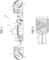
- FIG. 1 is a diagram illustrating a general arrangement of the inkjet image forming apparatus
- FIG. 2 is a block diagram illustrating a control system of the inkjet image forming apparatus.
- an image forming apparatus 100 includes a sheet supplier 1 that supplies a sheet S for image formation, an image former 2 that forms an image on the sheet S, a conveyer 3 that conveys the sheet S to the image former 2, a dryer 4 that dries the sheet S, and a sheet collector 5 that collects the sheet S having an image formed thereon.
- the image forming apparatus 100 according to the present embodiment further includes a controller 6 (see FIG. 2 ) that controls the sheet supplier 1, the image former 2, the conveyer 3, the dryer 4, and the sheet collector 5.
- the sheet supplier 1 includes a supply roller 11 having the elongated sheet S wound in roll form and a tension adjustment mechanism 12 that adjusts the tension applied to the sheet S.
- the supply roller 11 is configured to rotate in the direction of an arrow illustrated in FIG. 1 so that, as the supply roller 11 rotates, the sheet S is delivered.
- the tension adjustment mechanism 12 includes a plurality of rollers that has the sheet S placed therebetween to apply the tension. A part of these rollers is moved to adjust the tension of the sheet S, and the sheet S is delivered from the supply roller 11 at a constant tension.
- the image former 2 includes a head unit 13, which includes a liquid discharge unit that ejects a liquid ink onto the sheet S, and a platen 14, which includes a sheet support member that supports the conveyed sheet S.
- the head unit 13 includes a plurality of liquid discharge heads.
- the ink is ejected from each of the liquid discharge heads onto the sheet S based on the image data generated by the controller 6 so that the image is formed on the sheet S.
- the ink includes a liquid containing a color material, a solvent, and crystalline resin particles dispersed in the solvent.
- the crystalline resin includes a resin that undergoes a phase change and melts from a crystalline state to a liquid when heated above a predetermined melting point.
- the platen 14 is positioned so as to face the head unit 13 and support the lower surface of the sheet S supplied from the sheet supplier 1.
- the platen 14 is configured to be close to or away from the head unit 13 so that the distance between the head unit 13 and the sheet S may be kept constant.
- the conveyer 3 includes a plurality of conveyance rollers 15. Each of the conveyance rollers 15 rotates while the sheet S is placed between the conveyance rollers 15, and thus the sheet S is conveyed to the image former 2.
- the conveyer 3 may also include other conveyers such as a conveyance belt.
- the dryer 4 includes a heating drum 16 that heats the sheet S to promote drying of the ink on the sheet S.
- the heating drum 16 includes a cylindrical member that rotates while the sheet S is wound around the outer circumference thereof and has a heating source such as a halogen heater located inside.
- a non-contact heater such as a warm air generation device that blows warm air to the sheet S may also be used as a heater that heats the sheet S.
- the sheet collector 5 includes a collection roller 17 that winds and collects the sheet S and a tension adjustment mechanism 18 that adjusts the tension applied to the sheet S.
- the collection roller 17 is configured to rotate in the direction of an arrow illustrated in FIG. 1 so that, as the collection roller 17 rotates, the sheet S is wound and collected in roll form.
- the tension adjustment mechanism 18 includes a plurality of rollers, as in the tension adjustment mechanism 12 in the sheet supplier 1. A part of these rollers is moved to adjust the tension of the sheet S, and the sheet S is wound by the collection roller 17 at a constant tension.
- the controller 6 includes an information processing apparatus such as a personal computer (PC).
- the controller 6 generates image data to be formed on the sheet S and controls various operations of the sheet supplier 1, the image former 2, the conveyer 3, the dryer 4, and the sheet collector 5. For example, the controller 6 controls the rotation speeds of the supply roller 11, the collection roller 17, and each of the conveyance rollers 15, and the temperature of the heating source that heats the heating drum 16.
- FIG. 3 is an exploded perspective view of the liquid discharge head.
- FIG. 4 is a cross-sectional view of the liquid discharge head illustrated in FIG. 3 in the lateral direction (the direction of an arrow Y in FIG. 3 ).
- a liquid discharge head 20 includes a plurality of head main bodies 21, a base 22, a cover 23, a heat dissipation member 24, a manifold 25, a printed circuit board 26 (PCB), and a module case 27.
- head main bodies 21 a base 22, a cover 23, a heat dissipation member 24, a manifold 25, a printed circuit board 26 (PCB), and a module case 27.
- PCB printed circuit board 26
- the head main bodies 21 are held by the base 22 as a holder.
- the head main body 21 is first inserted into an opening 22c (see FIG. 4 ) included in the base 22. Then, the head main body 21 is bonded to the cover 23 that is bonded to the base 22.
- the cover 23 includes a hole 23a (see FIG. 3 ) corresponding to each of the head main bodies 21 so that a peripheral portion of the head main body 21 is bonded to an edge of the hole 23a. Then, the head main body 21 is fastened and secured to the base 22 with a screw.
- a flange portion of a common channel member 35 (see FIG. 4 ) is provided on the front side and the back side of the head main body 21 in the longitudinal direction (the direction perpendicular to the paper surface of FIG. 4 ), and the flange portion is fastened to the base 22 with a screw.
- the common channel member 35 is held by the base 22, and the head main body 21 is secured.
- the attachment structure of the head main body 21 and the base 22 is not limited thereto, and the head main body 21 may also be attached by bonding, swage, etc.
- the head main body 21 includes a nozzle plate 31 having a nozzle 30, a channel 32 including an individual chamber 41, or the like, communicating with the nozzle 30, a diaphragm 33 including a piezoelectric element 40, a holding 34 laminated on the diaphragm 33, the common channel member 35 stacked on the holding 34, etc.
- the common channel member 35 serves as a frame (nozzle protector holder) to hold the nozzle protector (cover 23).
- the individual chamber 41 is an example of a channel in the channel 32.
- the channel 32 includes, in addition to the individual chamber 41, a supply-side individual channel 42 communicating with the individual chamber 41 and a collection-side individual channel 43 communicating with the individual chamber 41.
- the holding 34 includes a supply-side intermediate individual channel 44 communicating with the supply-side individual channel 42 through an opening 33a of the diaphragm 33 and a collection-side intermediate individual channel 45 communicating with the collection-side individual channel 43 via an opening 33b of the diaphragm 33.
- the common channel member 35 (frame) includes a supply-side common channel 46 communicating with the supply-side intermediate individual channel 44 and a collection-side common channel 47 communicating with the collection-side intermediate individual channel 45.
- the supply-side common channel 46 communicates with a supply port 48 through a channel 51 in the manifold 25.
- the collection-side common channel 47 communicates with a collection port 49 through another channel 52 in the manifold 25.
- the PCB 26 is coupled to the piezoelectric element 40 of the head main body 21 through a flexible wiring member 50.
- the flexible wiring member 50 has a driver integrated circuit (IC) (drive circuit) 53 mounted thereon.
- IC driver integrated circuit
- the base 22 preferably has a material having a low coefficient of linear expansion.
- the material having a low coefficient of linear expansion include 42 alloy, which is iron with nickel added, or Invar ® materials.
- the base 22 has such a material, an increase in the temperature of the base 22 due to the heat generated by the liquid discharge head 20 causes a small amount of expansion of the base 22, which is unlikely to cause a misalignment of the nozzle, and the misalignment of the ink discharge position may be suppressed.
- the nozzle plate 31 and the diaphragm 33 include a silicon single-crystal and have the coefficient of linear expansion substantially the same as that of the base 22, the misalignment of the nozzle due to thermal expansion may be further reduced.
- FIG. 5 is a plan view of an example of the configuration of the head unit.
- the head unit 13 includes the two liquid discharge heads 20.
- Each of the liquid discharge heads 20 is arranged such that the lateral direction thereof (the direction of the arrow Y) is in a sheet conveyance direction A and the longitudinal direction thereof (the direction of an arrow X) is in the direction perpendicular to the sheet conveyance direction A.
- the "longitudinal direction" of the liquid discharge head 20 means, as illustrated in FIG. 5 , the longitudinal direction (the direction of the arrow X) of the liquid discharge head 20 extending in one direction when the liquid discharge head 20 is viewed in a direction perpendicular to a nozzle surface 31a where the nozzle 30 (see FIG. 4 ) is exposed.
- the "lateral direction” of the liquid discharge head 20 means the direction (the direction of the arrow Y) perpendicular to the longitudinal direction of the liquid discharge head 20 when the liquid discharge head 20 is viewed in the direction perpendicular to the nozzle surface 31a.
- the "longitudinal direction” and “lateral direction” of the liquid discharge head 20 described in the description below also have the same meanings.
- the head unit 13 illustrated in FIG. 5 includes what is called a line head unit.
- the ink is ejected through the nozzle of each of the head main bodies 21 to form an image on the sheet S without moving the head unit 13 with respect to the conveyed sheet S.
- the head unit also includes what is called a serial head unit that ejects the ink while moving the liquid discharge head in the main scanning direction (sheet width direction).
- FIG. 6 is a diagram illustrating an example of the configuration of a serial head unit 60.
- the serial head unit 60 includes a carriage 62 including a liquid discharge head 61, a guide member 63 (guide rod) that guides the carriage 62 in the main scanning direction, which is a sheet width direction B, and a drive device 64 that moves the carriage 62.
- the drive device 64 includes, for example, a motor 65, which includes a drive source, and a timing belt 68 that extends between a drive pulley 66 and a driven pulley 67.
- a motor 65 which includes a drive source
- a timing belt 68 that extends between a drive pulley 66 and a driven pulley 67.
- the liquid discharge head 61 ejects the ink in accordance with the image signal while the carriage 62 moves in the main scanning direction, and thus the image corresponding to one line is formed on the stopped sheet S. Then, while the sheet S moves by a predetermined amount in the direction of the arrow A in FIG. 6 , the back-and-forth movement of the carriage 62 and the ink discharge are repeatedly performed to sequentially form images on the sheet S.
- the cover 23 is provided around the head main body 21, and therefore, even when the sheet is conveyed close to the nozzle surface of the head main body 21, the contact of the sheet with the cover 23 may prevent the contact of the sheet with the nozzle surface. This may prevent damages to the nozzle and maintain stable ink discharge.
- the cover 23 when the conveyed sheet hits an outer edge face 230 of the cover 23, the impact received by the cover 23 at that moment may cause the cover 23 to separate from the nozzle plate 31, the base 22 (see FIG. 4 ), or the like.
- the fuzzy fiber of the conveyance object gets stuck with the corner or burr of the cover 23, which easily separate the cover 23.
- a foreign substance such as ink entering the head main body 21 through the separated area of the cover 23 may cause a failure or malfunction.
- the ink when the ink enters inside through the separated area of the cover 23 and adheres to a current-carrying portion such as the flexible wiring member 50 (see FIG. 4 ) inside the head main body 21, a failure may occur due to current leakage.
- the ink enters inside and adheres to the piezoelectric element 40 (see FIG. 4 ) inside the head main body 21, the subsequently solidified ink may avoid desirable driving of the piezoelectric element 40 and cause an ink discharge failure.
- the separation of the cover 23 causes various disadvantages such as malfunction and failure. Therefore, the following measures are taken according to the present embodiment.
- FIG. 7 is a schematic cross-sectional view of the liquid discharge head according to a first embodiment.
- the basic structure of the liquid discharge head according to the present embodiment is substantially the same as the liquid discharge head illustrated in FIGs. 3 and 4 above, the description will be omitted as appropriate for the already described part.
- the liquid discharge head 20 includes the nozzle plate 31 having the nozzle 30 (see FIG. 4 ), the cover 23 serving as a nozzle protector that protects the nozzle 30, the channel 32 including a channel including the supply-side individual channel 42 (see FIG. 4 ), the collection-side individual channel 43 (see FIG. 4 ), and the like, the common channel member 35 serving as a frame, the base 22 serving as a holder that holds the common channel member 35, and the like.
- the base 22 also serves as a nozzle protector holder that holds the nozzle protector (cover 23).
- the direction of an arrow Z indicates the liquid discharge direction in which the liquid (ink) is ejected through the nozzle of the nozzle plate 31.
- the nozzle surface 31a where the nozzle of the nozzle plate 31 is exposed, faces upward.
- the cover 23 covers at least part of the nozzle surface 31a other than the nozzle. According to the present embodiment, the cover 23 covers the edge portion and its nearby portion of the nozzle surface 31a.
- the center side (the right side in FIG. 7 ) of the nozzle surface 31a is “inner side” and the opposite side (the left side in FIG. 7 ) is “outer side", as illustrated in FIG. 7
- a portion on the outer side of the cover 23 is bonded to the base 22 through an adhesive 54.
- the base 22 is provided around the nozzle plate 31, the channel 32, and the common channel member 35, and the portion on the outer side of the cover 23 is bonded to an end surface 220 of the base 22 facing in the liquid discharge direction Z.
- an upper portion of the base 22 includes a peripheral wall 22b arranged around the nozzle plate 31 and the channel 32, and the base 22 serves as a nozzle protector holder that holds the cover 23 (nozzle protector).
- the portion on the inner side of the cover 23 is bonded to the nozzle plate 31 and the channel 32 through an adhesive 55.
- the channel 32 is bonded to the surface of the nozzle plate 31 (the lower surface of the nozzle plate 31 in FIG. 7 ) on the opposite side of the nozzle surface 31a, part of the channel 32 protrudes to the outer side from the edge portion of the nozzle plate 31, and the cover 23 is bonded to the outwardly protruding portion of the channel 32 and the edge portion periphery of the nozzle plate 31.
- the portions on both sides, the inner side and outer side, of the cover 23 are bonded to the respective members through the adhesives 54 and 55, and the space between each member and the cover 23 is sealed by the adhesives 54 and 55 to prevent the ink and other foreign matter from entering inside through the space.
- the cover 23 is bonded to the respective members through the adhesives 54 and 55, and therefore even when the conveyed sheet hits the cover 23, the cover 23 basically does not separate or fall off.
- the cover 23 may separate.
- a highly rigid resin member 70 is provided to cover the outwardly facing the outer edge face 230 of the cover 23, in other words, the outer edge face 230 (side surface) of the cover 23 on the side bonded to the base 22.
- the side surface may be also simply referred to as the "edge face 230" or “side surface” for convenience.
- the resin member 70 is provided between the outer edge face 230 of the cover 23 and the end surface 220 of the base 22 facing in the liquid discharge direction Z. As illustrated in FIG. 8 , the resin member 70 is provided over the entire outer edge face 230 (hatched area in FIG. 8 ) of the cover 23.
- the resin member 70 may prevent the sheet from coming into contact with and getting stuck with the outer edge face 230 of the cover 23.
- the impact on the cover 23 may also be reduced. Accordingly, the separation of the cover 23 is unlikely to occur, and therefore the entry of a foreign matter such as ink through the separated area may be suppressed. As a result, the possibility of malfunction and failure is reduced, and the reliability is improved.
- the resin member 70 does not protrude in the liquid discharge direction Z beyond the outer edge face 230 of the cover 23 and does not protrude to the outer side (the opposite side of the center side of the nozzle surface) from the end surface 220 of the base 22 facing in the liquid discharge direction Z. This may also prevent the sheet from getting stuck with the resin member 70.
- the resin member 70 has an inclined surface 70a that is inclined toward the inner side (the center side of the nozzle surface or the side of the outer edge face 230 of the cover 23) so as to gradually protrude in the liquid discharge direction Z.
- the sheet comes into contact with the resin member 70, the sheet is guided along the inclined surface 70a.
- the sheet is guided without getting stuck, which may ensure stable and smooth sheet conveyance.
- the resin member 70 has the inclined surface 70a, the impact when the sheet hits the resin member 70 (the inclined surface 70a) is also reduced.
- the effect of impact on the cover 23 may also be reduced, and the separation of the cover 23 may be further prevented.
- the base 22 also has an inclined surface 22a, as illustrated in FIG. 7 .
- the inclined surface 22a is provided on a portion (an upper portion in FIG. 7 ) of the base 22 adjacent to the resin member 70 and is formed to be continuous with the inclined surface 70a of the resin member 70.
- the inclined surface 22a of the base 22 is inclined toward the inner side so as to gradually protrude in the liquid discharge direction Z, in the same manner as the inclined surface 70a of the resin member 70.
- the inclined surfaces 22a and 70a of the base 22 and the resin member 70 have different inclination angles ⁇ 1 and ⁇ 2 with respect to the liquid discharge direction Z.
- the inclination angle ⁇ 1 of the inclined surface 70a of the resin member 70 is set to be larger than the inclination angle ⁇ 2 of the inclined surface 22a of the base 22. Accordingly, when the sheet comes into contact with the inclined surface 22a of the base 22, the sheet is smoothly guided from the inclined surface 22a of the base 22 to the inclined surface 70a of the resin member 70, which enables stable and smooth sheet conveyance.
- a height t (see FIG. 7 ) of the resin member 70 in the liquid discharge direction Z is preferably on the same level as the upper surface of the cover 23 in FIG. 7 , but the height t may be lower than the upper surface of the cover 23 as long as the height t is higher than the lower surface of the cover 23. That is, the resin member 70 may cover at least part of the outer edge face 230 of the cover 23. Even when the resin member 70 covers part of the outer edge face 230 of the cover 23, the contact of the sheet with the outer edge face 230 may be suppressed, and the possibility of separation of the cover 23 may be reduced.
- the highly rigid resin member 70 preferably has a Young's modulus of 1 GPa or more in terms of adhesion and strength. Furthermore, the resin member 70 preferably has a Young's modulus of 3 GPa or more.
- the Young's modulus also called the modulus of longitudinal elasticity, is the slope with respect to the stress during tensile test obtained using the following Equation (1).
- Equation (1) ⁇ represents tensile stress
- E the Young's modulus (modulus of longitudinal elasticity)
- ⁇ strain.
- the resin member 70 is provided over the entire outer edge face 230 of the cover 23, but when the contact area of the sheet with the outer edge face 230 is limited, the resin member 70 may also be provided at the contact area of the sheet (part of the outer edge face 230).
- the resin member 70 may be provided, in the entire outer edge face 230 of the cover 23, on a portion extending in the longitudinal direction (the direction of the arrow X in FIG. 8 ) of the liquid discharge head 20 or a portion extending in the lateral direction (the direction of the arrow Y in FIG. 8 ) of the liquid discharge head 20.
- a comparative example illustrated in FIG. 12 was created, and an evaluation test for the comparative example and the present embodiment was conducted.
- the comparative example has the same configuration as that of the present embodiment except that the highly rigid resin member 70 and the inclined surface 22a of the base 22 are not included.
- the liquid discharge head according to the comparative example or the present embodiment was mounted on the image forming apparatus and the sheet was conveyed, and it was checked whether the cover 23 was separated.
- the cover 23 of some of the liquid discharge heads was separated and failed, and part of the cover 23 of the other liquid discharge heads was not failed but separated.
- the cover 23 was not separated at all.
- FIG. 9 is a schematic cross-sectional view of the liquid discharge head according to a second embodiment.
- the base 22 (see FIG. 7 ) is not included. Therefore, according to the present embodiment, the cover 23 is bonded to the common channel member 35 (frame) instead of the base 22. Specifically, the common channel member 35 according to the present embodiment functions as a nozzle protector holder that is bonded to the cover 23 to hold the cover 23 (nozzle protector).
- a surface (upper surface in FIG. 9 ) of the common channel member 35 is bonded to a surface (lower surface in FIG. 9 ) of the channel 32 that is opposite to the surface (upper surface in FIG. 9 ) of the channel 32 bonded to the nozzle plate 31.
- a part of the common channel member 35 includes a peripheral wall 35b disposed exterior of the nozzle plate 31 and the channel 32.
- the cover 23 is bonded to a surface 350 of the peripheral wall 35b facing in the liquid discharge direction Z through an adhesive 56.
- an upper portion of the base 22 in FIG. 7 in particular corresponds to a peripheral wall 22b arranged around the nozzle plate 31 and the channel 32, and the base 22 corresponds to the nozzle protector holder that holds the cover 23.
- the second embodiment is different from the above-described embodiment in that the base 22 is not included and the cover 23 is bonded to the peripheral wall 35b of the common channel member 35, but even with this configuration, the cover 23 may separate when the sheet comes into contact with the outer edge face 230 of the cover 23.
- the highly rigid resin member 70 is provided to suppress the separation of the cover 23.
- the resin member 70 is provided between the outer edge face 230 of the cover 23 and the surface 350 of the peripheral wall 35b facing in the liquid discharge direction Z.
- the contact of the sheet with the outer edge face 230 of the cover 23 may be prevented, and the separation of the cover 23 may be suppressed.
- the range where the resin member 70 is provided may be the entire outer edge face 230 of the cover 23 or part of the outer edge face 230.
- the resin member 70 and the common channel member 35 have the inclined surface 70a and an inclined surface 35a, respectively.
- the inclined surfaces 70a and 35a are inclined toward the inner side so as to gradually protrude in the liquid discharge direction Z, and the inclination angle ⁇ 1 and an inclination angle ⁇ 3 with respect to the liquid discharge direction Z are set to have the same relation as that between the inclination angles ⁇ 1 and ⁇ 2 of the resin member 70 and the base 22 according to the above-described embodiment.
- the inclination angle ⁇ 1 of the inclined surface 70a of the resin member 70 is set to be larger than the inclination angle ⁇ 3 of the inclined surface 35a of the common channel member 35. Therefore, according to the present embodiment, too, the sheet may be smoothly guided from the inclined surface 35a of the common channel member 35 to the inclined surface 70a of the resin member 70, and a reduction of the impact due to the contact of the sheet and stable and smooth sheet conveyance may be achieved.
- FIG. 10 is a schematic cross-sectional view of the liquid discharge head according to a third embodiment.
- the resin member 70 covering the outer edge face 230 of the cover 23 includes the adhesive 54 that bonds the cover 23 and the base 22.
- the adhesive 54 may be spread to the outer side beyond the cover 23, and the spread portion may include the resin member 70 covering the outer edge face 230 of the cover 23.
- the amount of the adhesive 54 to spread may be adjusted by changing at least one of the following: the adhesive application position, the amount of applied adhesive, and the pressure applied to bond the cover 23.
- the inclined surface 70a which is the same as the one described above, may be formed in the resin member 70 by using methods such as forming the spread portion in a mold when the adhesive 54 is spread or cutting after the adhesive 54 is hardened.
- the configuration according to the present embodiment is also applicable to the configuration without the base 22 as illustrated in FIG. 9 as well as the configuration including the base 22 as illustrated in FIG. 10 .
- part of the adhesive 56 bonding the common channel member 35 and the cover 23 illustrated in FIG. 9 may include the resin member 70 covering the outer edge face 230 of the cover 23.
- FIG. 11 is a schematic cross-sectional view of the liquid discharge head according to a fourth embodiment.
- the resin member 70 covering the outer edge face 230 of the cover 23 is integrally formed with the base 22.
- the base 22 is made of a resin material having high rigidity (Young's modulus of 1 GPa or more)
- part of the base 22 (at least part of the peripheral wall 22b illustrated in FIG. 11 ) may cover the outer edge face 230 of the cover 23.
- the contact of the sheet with the outer edge face 230 of the cover 23 may be suppressed, and thus the separation of the cover 23 is unlikely to occur.
- the configuration according to the present embodiment is also applicable to the configuration without the base 22 as illustrated in FIG. 9 as well as the configuration including the base 22 as illustrated in FIG. 11 .
- part of the common channel member 35 (the peripheral wall 35b) illustrated in FIG. 9 may include the resin member 70 covering the outer edge face 230 of the cover 23.
- the "liquid discharge head” includes a functional component that discharges or ejects the liquid through the nozzle.
- the discharged liquid is not limited in particular and may be any liquid as long as the liquid has a viscosity or surface tension that allows discharge from the head, but the viscosity is preferably 30 mPa ⁇ s or less under the normal temperature and pressure or due to heating or cooling.
- the liquid includes a solution, suspension, emulsion, or the like, containing a solvent such as water or organic solvent, colorant such as dye or pigment, function-adding material such as polymerizable compound, resin, and surfactant, biocompatible material such as DNA, amino acid, protein, or calcium, and edible material such as natural colorant, and the liquid may be used for application such as inkjet ink, surface treatment liquid, component such as an electronic device or light emitting device, liquid for forming an electronic circuit resist pattern, material liquid for three-dimensional modeling, etc.
- a solvent such as water or organic solvent
- colorant such as dye or pigment
- function-adding material such as polymerizable compound, resin, and surfactant
- biocompatible material such as DNA, amino acid, protein, or calcium
- edible material such as natural colorant
- the liquid discharge head may include one head main body as well as a plurality of head main bodies as in the above-described embodiments.
- An energy generation source that discharges the liquid may include the one using a piezoelectric actuator (laminated piezoelectric element and thin-film piezoelectric element), a thermal actuator using an electricity-heat conversion element such as a heating resistor, an electrostatic actuator including a diaphragm and a counter electrode, etc.
- a piezoelectric actuator laminated piezoelectric element and thin-film piezoelectric element
- a thermal actuator using an electricity-heat conversion element such as a heating resistor
- an electrostatic actuator including a diaphragm and a counter electrode, etc.
- the "liquid discharge unit” includes the integration of a liquid discharge head and a functional part or mechanism and includes an assembly of parts related to liquid discharge.
- the “liquid discharge unit” includes the one combining the liquid discharge head and at least one of the configurations of the following: a head tank, a carriage, a supply mechanism, a maintenance mechanism, a main scanning movement mechanism, and a liquid circulation device.
- the integration includes, for example, securing the liquid discharge head and the functional part or mechanism by fastening, bonding, engagement, etc., or holding the liquid discharge head and the functional part or mechanism such that either one moves relative to the other one.
- the liquid discharge head and the functional part or mechanism may also be configured to be attachable to or detachable from each other.
- the liquid discharge head and the head tank may be integrated as a liquid discharge unit.
- the liquid discharge head and the head tank may be coupled to each other via a tube, or the like, to be integrated.
- a unit including a filter may also be added between the head tank and the liquid discharge head of the liquid discharge unit.
- the liquid discharge head and the carriage may be integrated as a liquid discharge unit.
- the liquid discharge head is movably held by a guide member included in part of a scanning movement mechanism so that the liquid discharge head and the scanning movement mechanism may be integrated as a liquid discharge unit.
- the liquid discharge head, the carriage, and the main scanning movement mechanism may be integrated.
- a cap member which is a part of the maintenance mechanism, is secured to the carriage to which the liquid discharge head is attached, so that the liquid discharge head, the carriage, and the maintenance mechanism may be integrated as a liquid discharge unit.
- a tube is coupled to the liquid discharge head to which the head tank or channel component is attached so that the liquid discharge head and the supply mechanism may be integrated as a liquid discharge unit.
- the liquid in a liquid storage source is supplied to the liquid discharge head via the tube.
- the main scanning movement mechanism also includes a guide member alone.
- the supply mechanism also includes a tube alone or a loader alone.
- the “liquid discharge apparatus” includes an apparatus that includes a liquid discharge head or a liquid discharge unit and drives the liquid discharge head to discharge the liquid.
- the liquid discharge apparatus also includes an apparatus that discharges the liquid into air or liquid as well as an apparatus that may discharge the liquid to an object to which the liquid may adhere.
- the "liquid discharge apparatus” may also include units regarding feeding, conveyance, and sheet ejection of an object to which the liquid may adhere and also a preprocessing apparatus, a post-processing apparatus, etc.
- liquid discharge apparatus examples include an image forming apparatus that discharges the ink to form an image on a sheet and a stereoscopic modeling apparatus (three-dimensional modeling apparatus) that discharges a modeling liquid onto a powder layer, which is obtained by forming powers in a layer form, so as to produce a stereoscopic model (three-dimensional model).
- the “liquid discharge apparatus” is not limited to an apparatus to discharge liquid to visualize meaningful images, such as letters or figures.
- the liquid discharge apparatus may be an apparatus to form arbitrarily images, such as arbitrarily patterns, or fabricate three-dimensional images.
- object to which the liquid may adhere refers to a discharge object to which the liquid may adhere at least temporarily, such as the object to which the liquid is firmly fixed after adherence or the object which the liquid permeates after adherence.
- Specific examples include media such as sheets such as paper, recording paper, recording sheets, film, and cloth, electronic components such as electronic s and piezoelectric elements, powder layers (powdered layers), organ models, and inspection cells, and any object to which the liquid adheres unless otherwise specified.
- the material of the above-described "object to which the liquid may adhere” may be any material as long as the liquid may adhere even temporarily, such as paper, yarns, fibers, woven fabrics, leathers, metals, plastics, glass, wood, and ceramics.
- the "sheet” may also be a continuous sheet (e.g., roll paper) formed to be elongated or a sheet (e.g., cut paper) previously cut into a predetermined size.
- the present embodiment is also applicable to apparatuses that discharge the liquid to discharge objects other than sheets.
- the "liquid discharge apparatus” includes an apparatus in which the liquid discharge head and the object to which the liquid may adhere are moved relative to each other, but is not limited thereto. Specific examples include a serial apparatus (see FIG. 6 ) that moves the liquid discharge head and a line apparatus (see FIG. 5 ) that does not move the liquid discharge head.
- the “liquid discharge apparatus” further includes, for example, a treatment liquid application apparatus that discharges a treatment liquid onto paper to apply the treatment liquid to a surface of the paper for the purpose of modifying the surface of the paper, an ejection granulation apparatus that ejects a composition liquid, in which a raw material is dispersed in a solution, through a nozzle to granulate fine particles of the raw material.
- a treatment liquid application apparatus that discharges a treatment liquid onto paper to apply the treatment liquid to a surface of the paper for the purpose of modifying the surface of the paper
- an ejection granulation apparatus that ejects a composition liquid, in which a raw material is dispersed in a solution, through a nozzle to granulate fine particles of the raw material.
- a liquid discharge head (20) includes: a nozzle plate (31) having: a nozzle surface (31a); and a nozzle (30) in the nozzle plate (31), a liquid being discharged from the nozzle (30) of the nozzle surface (31a) side in a liquid discharge direction; a nozzle protector (23) covering at least a part of the nozzle surface (31a) of the nozzle plate (31) other than the nozzle (30); a nozzle protector holder (22, 35) including a peripheral wall (22b, 35b) bonded to a peripheral end portion of the nozzle protector (23); and a resin member (70) between an edge face of the peripheral end portion of the nozzle protector (23) and an end surface (220) of the peripheral wall (35b) facing the nozzle protector (23).
- the resin member (70) includes an adhesive to bond the nozzle protector (23) and the nozzle protector holder (22, 35).
- the liquid discharge head further includes: a channel (32) having a first surface bonded to a bonding surface of the nozzle plate (31) opposite to the nozzle surface (31a), the channel (32) including a channel (41) communicating with the nozzle (30).
- the nozzle protector holder (22, 35) includes a frame (35) bonded to a second surface of the channel (32) opposite to the first surface.
- the liquid discharge head further includes: a channel (32) having a first surface bonded to a bonding surface of the nozzle plate (31) opposite to the nozzle surface (31a), the channel (32) including a channel (41) communicating with the nozzle (30); and a frame (35) bonded to a second surface of the channel (32) opposite to the first surface.
- the nozzle protector holder (22, 35) includes a base (22) holding the frame (35).
- the resin member (70) has a first inclined surface (70a) inclined toward the edge face of the peripheral end portion of the nozzle protector (23)
- the peripheral wall (35b) has a second inclined surface (22a) that is inclined toward the edge face of the peripheral end portion of the nozzle protector (23).
- a first inclination angle ( ⁇ 1) of the first inclined surface (70a) of the resin member (70) with respect to the liquid discharge direction is larger than a second inclination angle ( ⁇ 2) of the second inclined surface (22a) of the end surface (220) of the peripheral wall (22b) with respect to the liquid discharge direction.
- the resin member (70) has a Young's modulus of 3 GPa or more.
- a liquid discharge apparatus includes the liquid discharge head according to any one of Aspect 1 to 8.
- a liquid discharge head (20) includes: a nozzle plate (31) having: a nozzle surface (31a); and a nozzle (30) in the nozzle plate (31), a liquid being discharged from the nozzle (30) of the nozzle surface (31a) side in a liquid discharge direction; a nozzle protector (23) covering at least a part of the nozzle surface (31a) of the nozzle plate (31) other than the nozzle (30); and a nozzle protector holder (22, 35) including a peripheral wall (35b) bonded to a peripheral end portion of the nozzle protector (23). At least a part of the peripheral wall (35b) is made of a resin member (70), and the peripheral wall (35b) covers the edge face of the peripheral end portion of the nozzle protector (23).
Landscapes
- Engineering & Computer Science (AREA)
- Manufacturing & Machinery (AREA)
- Ink Jet (AREA)
- Particle Formation And Scattering Control In Inkjet Printers (AREA)
Abstract
Description
- The present embodiment relates to a liquid discharge head and a liquid discharge apparatus.
- As liquid discharge apparatuses that discharge a liquid, there are known inkjet image forming apparatuses that discharge an ink onto a sheet such as paper to form an image.
- Inkjet image forming apparatuses include a liquid discharge head having a nozzle to discharge the ink. When a sheet is conveyed to a position facing the liquid discharge head, the ink is discharged through the nozzle to form an image on the sheet. When the sheet comes into contact with the nozzle, the nozzle may be damaged, which may avoid stable ink discharge. Therefore, some inkjet image forming apparatuses include a nozzle protector that protects the nozzle (see
Japanese Unexamined Patent Application Publication No. 2011-56922 - For example, the nozzle protector is bonded to a peripheral portion of a nozzle plate having the nozzle, a frame, or the like, and when the conveyed sheet hits an edge face of the nozzle protector, the impact may cause the nozzle protector to separate.
- It is an object of the embodiments of the present disclosure to suppress the separation of the nozzle protector.
- In an aspect of this disclosure, a liquid discharge head includes: a nozzle plate having: a nozzle surface; and a nozzle in the nozzle plate, a liquid being discharged from the nozzle of the nozzle surface side in a liquid discharge direction; a nozzle protector covering at least a part of the nozzle surface of the nozzle plate other than the nozzle; a nozzle protector holder including a peripheral wall bonded to a peripheral end portion of the nozzle protector; and a resin member between an edge face of the peripheral end portion of the nozzle protector and an end surface of the peripheral wall facing the nozzle protector.
- According to the present embodiment, it is possible to suppress the separation of the nozzle protector.
- A more complete appreciation of the disclosure and many of the attendant advantages and features thereof can be readily obtained and understood from the following detailed description with reference to the accompanying drawings, wherein:
-
FIG. 1 is a diagram illustrating a general arrangement of an inkjet image forming apparatus according to an embodiment. -
FIG. 2 is a block diagram illustrating a control system of the inkjet image forming apparatus according to the embodiment. -
FIG. 3 is an exploded perspective view of an example of a configuration of a liquid discharge head. -
FIG. 4 is a cross-sectional view of the liquid discharge head illustrated inFIG. 3 in a lateral direction. -
FIG. 5 is a plan view of an example of a configuration of a line head unit. -
FIG. 6 is a plan view of an example of a configuration of a serial head unit. -
FIG. 7 is a schematic cross-sectional view of the liquid discharge head according to a first embodiment. -
FIG. 8 is a plan view of the liquid discharge head according to the first embodiment. -
FIG. 9 is a schematic cross-sectional view of the liquid discharge head according to a second embodiment. -
FIG. 10 is a schematic cross-sectional view of the liquid discharge head according to a third embodiment. -
FIG. 11 is a schematic cross-sectional view of the liquid discharge head according to a fourth embodiment. -
FIG. 12 is a schematic cross-sectional view of the liquid discharge head according to a comparative example. - The accompanying drawings are intended to depict embodiments of the present invention and should not be interpreted to limit the scope thereof. The accompanying drawings are not to be considered as drawn to scale unless explicitly noted. Also, identical or similar reference numerals designate identical or similar components throughout the several views.
- In describing embodiments illustrated in the drawings, specific terminology is employed for the sake of clarity. However, the disclosure of this specification is not intended to be limited to the specific terminology so selected and it is to be understood that each specific element includes all technical equivalents that have a similar function, operate in a similar manner, and achieve a similar result.
- Referring now to the drawings, embodiments of the present disclosure are described below. As used herein, the singular forms "a", "an", and "the" are intended to include the plural forms as well, unless the context clearly indicates otherwise.
- Embodiments will be described below with reference to the accompanying drawings. In each of the drawings for describing the embodiments, components such as members and elements having the same function or shape will be denoted by the same reference numeral as long as the components are distinguishable, and thus the description thereof will be omitted after the components are described once.
- First, a configuration of an inkjet image forming apparatus, which is a liquid discharge apparatus according to an embodiment, will be described with reference to
FIGs. 1 and 2. FIG. 1 is a diagram illustrating a general arrangement of the inkjet image forming apparatus, andFIG. 2 is a block diagram illustrating a control system of the inkjet image forming apparatus. - As illustrated in
FIG. 1 , animage forming apparatus 100 according to the present embodiment includes asheet supplier 1 that supplies a sheet S for image formation, an image former 2 that forms an image on the sheet S, aconveyer 3 that conveys the sheet S to the image former 2, adryer 4 that dries the sheet S, and asheet collector 5 that collects the sheet S having an image formed thereon. Theimage forming apparatus 100 according to the present embodiment further includes a controller 6 (seeFIG. 2 ) that controls thesheet supplier 1, the image former 2, theconveyer 3, thedryer 4, and thesheet collector 5. - The
sheet supplier 1 includes asupply roller 11 having the elongated sheet S wound in roll form and atension adjustment mechanism 12 that adjusts the tension applied to the sheet S. Thesupply roller 11 is configured to rotate in the direction of an arrow illustrated inFIG. 1 so that, as thesupply roller 11 rotates, the sheet S is delivered. Thetension adjustment mechanism 12 includes a plurality of rollers that has the sheet S placed therebetween to apply the tension. A part of these rollers is moved to adjust the tension of the sheet S, and the sheet S is delivered from thesupply roller 11 at a constant tension. - The image former 2 includes a
head unit 13, which includes a liquid discharge unit that ejects a liquid ink onto the sheet S, and aplaten 14, which includes a sheet support member that supports the conveyed sheet S. Thehead unit 13 includes a plurality of liquid discharge heads. The ink is ejected from each of the liquid discharge heads onto the sheet S based on the image data generated by thecontroller 6 so that the image is formed on the sheet S. Here, the ink includes a liquid containing a color material, a solvent, and crystalline resin particles dispersed in the solvent. The crystalline resin includes a resin that undergoes a phase change and melts from a crystalline state to a liquid when heated above a predetermined melting point. Theplaten 14 is positioned so as to face thehead unit 13 and support the lower surface of the sheet S supplied from thesheet supplier 1. Theplaten 14 is configured to be close to or away from thehead unit 13 so that the distance between thehead unit 13 and the sheet S may be kept constant. - The
conveyer 3 includes a plurality ofconveyance rollers 15. Each of theconveyance rollers 15 rotates while the sheet S is placed between theconveyance rollers 15, and thus the sheet S is conveyed to the image former 2. Theconveyer 3 may also include other conveyers such as a conveyance belt. - The
dryer 4 includes aheating drum 16 that heats the sheet S to promote drying of the ink on the sheet S. Theheating drum 16 includes a cylindrical member that rotates while the sheet S is wound around the outer circumference thereof and has a heating source such as a halogen heater located inside. In addition to a contact heater such as theheating drum 16, a non-contact heater such as a warm air generation device that blows warm air to the sheet S may also be used as a heater that heats the sheet S. - The
sheet collector 5 includes acollection roller 17 that winds and collects the sheet S and atension adjustment mechanism 18 that adjusts the tension applied to the sheet S. Thecollection roller 17 is configured to rotate in the direction of an arrow illustrated inFIG. 1 so that, as thecollection roller 17 rotates, the sheet S is wound and collected in roll form. Thetension adjustment mechanism 18 includes a plurality of rollers, as in thetension adjustment mechanism 12 in thesheet supplier 1. A part of these rollers is moved to adjust the tension of the sheet S, and the sheet S is wound by thecollection roller 17 at a constant tension. - The
controller 6 includes an information processing apparatus such as a personal computer (PC). Thecontroller 6 generates image data to be formed on the sheet S and controls various operations of thesheet supplier 1, the image former 2, theconveyer 3, thedryer 4, and thesheet collector 5. For example, thecontroller 6 controls the rotation speeds of thesupply roller 11, thecollection roller 17, and each of theconveyance rollers 15, and the temperature of the heating source that heats theheating drum 16. - Next, an example of the configuration of the liquid discharge head will be described with reference to
FIGs. 3 and4 . -
FIG. 3 is an exploded perspective view of the liquid discharge head.FIG. 4 is a cross-sectional view of the liquid discharge head illustrated inFIG. 3 in the lateral direction (the direction of an arrow Y inFIG. 3 ). - As illustrated in
FIG. 3 , aliquid discharge head 20 includes a plurality of headmain bodies 21, abase 22, acover 23, aheat dissipation member 24, a manifold 25, a printed circuit board 26 (PCB), and amodule case 27. - The head
main bodies 21 are held by the base 22 as a holder. To attach the headmain body 21 to thebase 22, the headmain body 21 is first inserted into anopening 22c (seeFIG. 4 ) included in thebase 22. Then, the headmain body 21 is bonded to thecover 23 that is bonded to thebase 22. Thecover 23 includes ahole 23a (seeFIG. 3 ) corresponding to each of the headmain bodies 21 so that a peripheral portion of the headmain body 21 is bonded to an edge of thehole 23a. Then, the headmain body 21 is fastened and secured to the base 22 with a screw. - Specifically, a flange portion of a common channel member 35 (see
FIG. 4 ) is provided on the front side and the back side of the headmain body 21 in the longitudinal direction (the direction perpendicular to the paper surface ofFIG. 4 ), and the flange portion is fastened to the base 22 with a screw. - Accordingly, the
common channel member 35 is held by thebase 22, and the headmain body 21 is secured. The attachment structure of the headmain body 21 and thebase 22 is not limited thereto, and the headmain body 21 may also be attached by bonding, swage, etc. - As illustrated in
FIG. 4 , the headmain body 21 includes anozzle plate 31 having anozzle 30, achannel 32 including an individual chamber 41, or the like, communicating with thenozzle 30, a diaphragm 33 including apiezoelectric element 40, a holding 34 laminated on the diaphragm 33, thecommon channel member 35 stacked on the holding 34, etc. Thecommon channel member 35 serves as a frame (nozzle protector holder) to hold the nozzle protector (cover 23). The individual chamber 41 is an example of a channel in thechannel 32. - The
channel 32 includes, in addition to the individual chamber 41, a supply-sideindividual channel 42 communicating with the individual chamber 41 and a collection-side individual channel 43 communicating with the individual chamber 41. The holding 34 includes a supply-side intermediateindividual channel 44 communicating with the supply-sideindividual channel 42 through anopening 33a of the diaphragm 33 and a collection-side intermediateindividual channel 45 communicating with the collection-side individual channel 43 via anopening 33b of the diaphragm 33. - The common channel member 35 (frame) includes a supply-side
common channel 46 communicating with the supply-side intermediateindividual channel 44 and a collection-sidecommon channel 47 communicating with the collection-side intermediateindividual channel 45. The supply-sidecommon channel 46 communicates with asupply port 48 through achannel 51 in themanifold 25. - The collection-side
common channel 47 communicates with acollection port 49 through anotherchannel 52 in themanifold 25. - The
PCB 26 is coupled to thepiezoelectric element 40 of the headmain body 21 through aflexible wiring member 50. Theflexible wiring member 50 has a driver integrated circuit (IC) (drive circuit) 53 mounted thereon. - The base 22 preferably has a material having a low coefficient of linear expansion. Examples of the material having a low coefficient of linear expansion include 42 alloy, which is iron with nickel added, or Invar® materials. When the
base 22 has such a material, an increase in the temperature of thebase 22 due to the heat generated by theliquid discharge head 20 causes a small amount of expansion of thebase 22, which is unlikely to cause a misalignment of the nozzle, and the misalignment of the ink discharge position may be suppressed. When thenozzle plate 31 and the diaphragm 33 include a silicon single-crystal and have the coefficient of linear expansion substantially the same as that of thebase 22, the misalignment of the nozzle due to thermal expansion may be further reduced. -
FIG. 5 is a plan view of an example of the configuration of the head unit. - In the example illustrated in
FIG. 5 , thehead unit 13 includes the two liquid discharge heads 20. Each of the liquid discharge heads 20 is arranged such that the lateral direction thereof (the direction of the arrow Y) is in a sheet conveyance direction A and the longitudinal direction thereof (the direction of an arrow X) is in the direction perpendicular to the sheet conveyance direction A. Here, the "longitudinal direction" of theliquid discharge head 20 means, as illustrated inFIG. 5 , the longitudinal direction (the direction of the arrow X) of theliquid discharge head 20 extending in one direction when theliquid discharge head 20 is viewed in a direction perpendicular to anozzle surface 31a where the nozzle 30 (seeFIG. 4 ) is exposed. The "lateral direction" of theliquid discharge head 20 means the direction (the direction of the arrow Y) perpendicular to the longitudinal direction of theliquid discharge head 20 when theliquid discharge head 20 is viewed in the direction perpendicular to thenozzle surface 31a. The "longitudinal direction" and "lateral direction" of theliquid discharge head 20 described in the description below also have the same meanings. - The
head unit 13 illustrated inFIG. 5 includes what is called a line head unit. When the sheet S is conveyed to a position facing thehead unit 13, the ink is ejected through the nozzle of each of the headmain bodies 21 to form an image on the sheet S without moving thehead unit 13 with respect to the conveyed sheet S. - In addition to the above-described line head unit, the head unit also includes what is called a serial head unit that ejects the ink while moving the liquid discharge head in the main scanning direction (sheet width direction).
-
FIG. 6 is a diagram illustrating an example of the configuration of aserial head unit 60. As illustrated inFIG. 6 , theserial head unit 60 includes acarriage 62 including aliquid discharge head 61, a guide member 63 (guide rod) that guides thecarriage 62 in the main scanning direction, which is a sheet width direction B, and adrive device 64 that moves thecarriage 62. - The
drive device 64 includes, for example, amotor 65, which includes a drive source, and atiming belt 68 that extends between adrive pulley 66 and a drivenpulley 67. When themotor 65 is driven and thedrive pulley 66 is rotated, thetiming belt 68 moves circumferentially, and thus thecarriage 62 moves in the main scanning direction along theguide member 63. The rotation direction of themotor 65 is switched between one direction and the opposite direction so that thecarriage 62 may move back and forth in the main scanning direction. - In the above-described
serial head unit 60, theliquid discharge head 61 ejects the ink in accordance with the image signal while thecarriage 62 moves in the main scanning direction, and thus the image corresponding to one line is formed on the stopped sheet S. Then, while the sheet S moves by a predetermined amount in the direction of the arrow A inFIG. 6 , the back-and-forth movement of thecarriage 62 and the ink discharge are repeatedly performed to sequentially form images on the sheet S. - In the above-described head unit (liquid discharge head), as illustrated in
FIG. 3 , thecover 23 is provided around the headmain body 21, and therefore, even when the sheet is conveyed close to the nozzle surface of the headmain body 21, the contact of the sheet with thecover 23 may prevent the contact of the sheet with the nozzle surface. This may prevent damages to the nozzle and maintain stable ink discharge. - However, when the conveyed sheet hits an
outer edge face 230 of thecover 23, the impact received by thecover 23 at that moment may cause thecover 23 to separate from thenozzle plate 31, the base 22 (seeFIG. 4 ), or the like. In particular, when a fibrous conveyance object such as cloth is conveyed, the fuzzy fiber of the conveyance object gets stuck with the corner or burr of thecover 23, which easily separate thecover 23. When thecover 23 is separated, a foreign substance such as ink entering the headmain body 21 through the separated area of thecover 23 may cause a failure or malfunction. - For example, when the ink enters inside through the separated area of the
cover 23 and adheres to a current-carrying portion such as the flexible wiring member 50 (seeFIG. 4 ) inside the headmain body 21, a failure may occur due to current leakage. When the ink enters inside and adheres to the piezoelectric element 40 (seeFIG. 4 ) inside the headmain body 21, the subsequently solidified ink may avoid desirable driving of thepiezoelectric element 40 and cause an ink discharge failure. - As described above, the separation of the
cover 23 causes various disadvantages such as malfunction and failure. Therefore, the following measures are taken according to the present embodiment. -
FIG. 7 is a schematic cross-sectional view of the liquid discharge head according to a first embodiment. As the basic structure of the liquid discharge head according to the present embodiment is substantially the same as the liquid discharge head illustrated inFIGs. 3 and4 above, the description will be omitted as appropriate for the already described part. - As illustrated in
FIG. 7 , theliquid discharge head 20 according to the present embodiment includes thenozzle plate 31 having the nozzle 30 (seeFIG. 4 ), thecover 23 serving as a nozzle protector that protects thenozzle 30, thechannel 32 including a channel including the supply-side individual channel 42 (seeFIG. 4 ), the collection-side individual channel 43 (seeFIG. 4 ), and the like, thecommon channel member 35 serving as a frame, thebase 22 serving as a holder that holds thecommon channel member 35, and the like. InFIG. 7 , thebase 22 also serves as a nozzle protector holder that holds the nozzle protector (cover 23). - In
FIG. 7 , the direction of an arrow Z indicates the liquid discharge direction in which the liquid (ink) is ejected through the nozzle of thenozzle plate 31. Specifically, inFIG. 7 , thenozzle surface 31a, where the nozzle of thenozzle plate 31 is exposed, faces upward. - The
cover 23 covers at least part of thenozzle surface 31a other than the nozzle. According to the present embodiment, thecover 23 covers the edge portion and its nearby portion of thenozzle surface 31a. - Here, when the center side (the right side in
FIG. 7 ) of thenozzle surface 31a is "inner side" and the opposite side (the left side inFIG. 7 ) is "outer side", as illustrated inFIG. 7 , a portion on the outer side of thecover 23 is bonded to the base 22 through an adhesive 54. Thebase 22 is provided around thenozzle plate 31, thechannel 32, and thecommon channel member 35, and the portion on the outer side of thecover 23 is bonded to anend surface 220 of the base 22 facing in the liquid discharge direction Z. - As illustrated in
FIG. 7 , an upper portion of thebase 22 includes aperipheral wall 22b arranged around thenozzle plate 31 and thechannel 32, and thebase 22 serves as a nozzle protector holder that holds the cover 23 (nozzle protector). - The portion on the inner side of the
cover 23 is bonded to thenozzle plate 31 and thechannel 32 through an adhesive 55. Thechannel 32 is bonded to the surface of the nozzle plate 31 (the lower surface of thenozzle plate 31 inFIG. 7 ) on the opposite side of thenozzle surface 31a, part of thechannel 32 protrudes to the outer side from the edge portion of thenozzle plate 31, and thecover 23 is bonded to the outwardly protruding portion of thechannel 32 and the edge portion periphery of thenozzle plate 31. - As described above, the portions on both sides, the inner side and outer side, of the
cover 23 are bonded to the respective members through theadhesives cover 23 is sealed by theadhesives cover 23 is bonded to the respective members through theadhesives cover 23, thecover 23 basically does not separate or fall off. - However, when the sheet repeatedly hits the
outer edge face 230 of thecover 23 facing the outer side (the opposite side of the center side of the nozzle surface) or the fibrous sheet gets stuck with the edge (corner), burr formed on the edge of theouter edge face 230, or the like, while the sheet is conveyed from the left side inFIG. 7 , thecover 23 may separate. - Therefore, according to the present embodiment illustrated in
FIG. 7 , a highlyrigid resin member 70 is provided to cover the outwardly facing theouter edge face 230 of thecover 23, in other words, the outer edge face 230 (side surface) of thecover 23 on the side bonded to thebase 22. Hereinafter, the side surface may be also simply referred to as the "edge face 230" or "side surface" for convenience. - The
resin member 70 is provided between theouter edge face 230 of thecover 23 and theend surface 220 of the base 22 facing in the liquid discharge direction Z. As illustrated inFIG. 8 , theresin member 70 is provided over the entire outer edge face 230 (hatched area inFIG. 8 ) of thecover 23. - As described above, according to the present embodiment, as the highly
rigid resin member 70 is provided over the entireouter edge face 230 of thecover 23, theresin member 70 may prevent the sheet from coming into contact with and getting stuck with theouter edge face 230 of thecover 23. As the direct contact of the sheet with theouter edge face 230 of thecover 23 may be prevented, the impact on thecover 23 may also be reduced. Accordingly, the separation of thecover 23 is unlikely to occur, and therefore the entry of a foreign matter such as ink through the separated area may be suppressed. As a result, the possibility of malfunction and failure is reduced, and the reliability is improved. - As illustrated in
FIG. 7 , according to the present embodiment, theresin member 70 does not protrude in the liquid discharge direction Z beyond theouter edge face 230 of thecover 23 and does not protrude to the outer side (the opposite side of the center side of the nozzle surface) from theend surface 220 of the base 22 facing in the liquid discharge direction Z. This may also prevent the sheet from getting stuck with theresin member 70. Theresin member 70 has aninclined surface 70a that is inclined toward the inner side (the center side of the nozzle surface or the side of theouter edge face 230 of the cover 23) so as to gradually protrude in the liquid discharge direction Z. - Therefore, when the sheet comes into contact with the
resin member 70, the sheet is guided along theinclined surface 70a. As described above, according to the present embodiment, even when the sheet comes into contact with theresin member 70, the sheet is guided without getting stuck, which may ensure stable and smooth sheet conveyance. As theresin member 70 has theinclined surface 70a, the impact when the sheet hits the resin member 70 (theinclined surface 70a) is also reduced. Thus, the effect of impact on thecover 23 may also be reduced, and the separation of thecover 23 may be further prevented. - According to the present embodiment, the
base 22 also has aninclined surface 22a, as illustrated inFIG. 7 . Theinclined surface 22a is provided on a portion (an upper portion inFIG. 7 ) of the base 22 adjacent to theresin member 70 and is formed to be continuous with theinclined surface 70a of theresin member 70. Theinclined surface 22a of thebase 22 is inclined toward the inner side so as to gradually protrude in the liquid discharge direction Z, in the same manner as theinclined surface 70a of theresin member 70. - According to the present embodiment, the
inclined surfaces base 22 and theresin member 70 have different inclination angles θ1 and θ2 with respect to the liquid discharge direction Z. Specifically, the inclination angle θ1 of theinclined surface 70a of theresin member 70 is set to be larger than the inclination angle θ2 of theinclined surface 22a of thebase 22. Accordingly, when the sheet comes into contact with theinclined surface 22a of thebase 22, the sheet is smoothly guided from theinclined surface 22a of the base 22 to theinclined surface 70a of theresin member 70, which enables stable and smooth sheet conveyance. - A height t (see
FIG. 7 ) of theresin member 70 in the liquid discharge direction Z is preferably on the same level as the upper surface of thecover 23 inFIG. 7 , but the height t may be lower than the upper surface of thecover 23 as long as the height t is higher than the lower surface of thecover 23. That is, theresin member 70 may cover at least part of theouter edge face 230 of thecover 23. Even when theresin member 70 covers part of theouter edge face 230 of thecover 23, the contact of the sheet with theouter edge face 230 may be suppressed, and the possibility of separation of thecover 23 may be reduced. - The highly
rigid resin member 70 preferably has a Young's modulus of 1 GPa or more in terms of adhesion and strength. Furthermore, theresin member 70 preferably has a Young's modulus of 3 GPa or more. The Young's modulus, also called the modulus of longitudinal elasticity, is the slope with respect to the stress during tensile test obtained using the following Equation (1). In Equation (1), σ represents tensile stress, E represents the Young's modulus (modulus of longitudinal elasticity), and ε represents strain.
(Equation 1)
- According to the present embodiment, as illustrated in
FIG. 8 , theresin member 70 is provided over the entireouter edge face 230 of thecover 23, but when the contact area of the sheet with theouter edge face 230 is limited, theresin member 70 may also be provided at the contact area of the sheet (part of the outer edge face 230). For example, theresin member 70 may be provided, in the entireouter edge face 230 of thecover 23, on a portion extending in the longitudinal direction (the direction of the arrow X inFIG. 8 ) of theliquid discharge head 20 or a portion extending in the lateral direction (the direction of the arrow Y inFIG. 8 ) of theliquid discharge head 20. - In order to confirm the effect of the present embodiment, a comparative example illustrated in
FIG. 12 was created, and an evaluation test for the comparative example and the present embodiment was conducted. The comparative example has the same configuration as that of the present embodiment except that the highlyrigid resin member 70 and theinclined surface 22a of the base 22 are not included. In this test, the liquid discharge head according to the comparative example or the present embodiment was mounted on the image forming apparatus and the sheet was conveyed, and it was checked whether thecover 23 was separated. - As a result, in the comparative example, the
cover 23 of some of the liquid discharge heads was separated and failed, and part of thecover 23 of the other liquid discharge heads was not failed but separated. Conversely, according to the present embodiment, thecover 23 was not separated at all. Thus, with the configuration according to the present embodiment, it was confirmed that the separation of thecover 23 was effectively suppressed. - Next, an embodiment different from the above-described embodiment (the first embodiment) will be described. In the description below, the parts different from the above embodiment will be primarily described, and the description of the other parts will be omitted as appropriate as the other parts have basically the same configuration.
-
FIG. 9 is a schematic cross-sectional view of the liquid discharge head according to a second embodiment. - According to the second embodiment illustrated in
FIG. 9 , the base 22 (seeFIG. 7 ) is not included. Therefore, according to the present embodiment, thecover 23 is bonded to the common channel member 35 (frame) instead of thebase 22. Specifically, thecommon channel member 35 according to the present embodiment functions as a nozzle protector holder that is bonded to thecover 23 to hold the cover 23 (nozzle protector). - As illustrated in
FIG. 9 , a surface (upper surface inFIG. 9 ) of thecommon channel member 35 is bonded to a surface (lower surface inFIG. 9 ) of thechannel 32 that is opposite to the surface (upper surface inFIG. 9 ) of thechannel 32 bonded to thenozzle plate 31. A part of thecommon channel member 35 includes aperipheral wall 35b disposed exterior of thenozzle plate 31 and thechannel 32. Thecover 23 is bonded to asurface 350 of theperipheral wall 35b facing in the liquid discharge direction Z through an adhesive 56. - According to the embodiment (the first embodiment) illustrated in
FIG. 7 above, an upper portion of the base 22 inFIG. 7 in particular corresponds to aperipheral wall 22b arranged around thenozzle plate 31 and thechannel 32, and thebase 22 corresponds to the nozzle protector holder that holds thecover 23. - As described above, the second embodiment is different from the above-described embodiment in that the
base 22 is not included and thecover 23 is bonded to theperipheral wall 35b of thecommon channel member 35, but even with this configuration, thecover 23 may separate when the sheet comes into contact with theouter edge face 230 of thecover 23. - Therefore, according to the present embodiment, as in the above-described embodiment, the highly
rigid resin member 70 is provided to suppress the separation of thecover 23. Specifically, according to the present embodiment, theresin member 70 is provided between theouter edge face 230 of thecover 23 and thesurface 350 of theperipheral wall 35b facing in the liquid discharge direction Z. - Thus, according to the present embodiment, too, the contact of the sheet with the
outer edge face 230 of thecover 23 may be prevented, and the separation of thecover 23 may be suppressed. The range where theresin member 70 is provided may be the entireouter edge face 230 of thecover 23 or part of theouter edge face 230. - According to the present embodiment, too, the
resin member 70 and the common channel member 35 (theperipheral wall 35b) have theinclined surface 70a and aninclined surface 35a, respectively. Theinclined surfaces resin member 70 and the base 22 according to the above-described embodiment. - That is, the inclination angle θ1 of the
inclined surface 70a of theresin member 70 is set to be larger than the inclination angle θ3 of theinclined surface 35a of thecommon channel member 35. Therefore, according to the present embodiment, too, the sheet may be smoothly guided from theinclined surface 35a of thecommon channel member 35 to theinclined surface 70a of theresin member 70, and a reduction of the impact due to the contact of the sheet and stable and smooth sheet conveyance may be achieved. -
FIG. 10 is a schematic cross-sectional view of the liquid discharge head according to a third embodiment. - According to the third embodiment illustrated in
FIG. 10 , theresin member 70 covering theouter edge face 230 of thecover 23 includes the adhesive 54 that bonds thecover 23 and thebase 22. When the rigidity of the adhesive 54 is high (the Young's modulus is 1 GPa or more), the adhesive 54 may be spread to the outer side beyond thecover 23, and the spread portion may include theresin member 70 covering theouter edge face 230 of thecover 23. The amount of the adhesive 54 to spread may be adjusted by changing at least one of the following: the adhesive application position, the amount of applied adhesive, and the pressure applied to bond thecover 23. Theinclined surface 70a, which is the same as the one described above, may be formed in theresin member 70 by using methods such as forming the spread portion in a mold when the adhesive 54 is spread or cutting after the adhesive 54 is hardened. - The configuration according to the present embodiment is also applicable to the configuration without the base 22 as illustrated in
FIG. 9 as well as the configuration including the base 22 as illustrated inFIG. 10 . - That is, part of the adhesive 56 bonding the
common channel member 35 and thecover 23 illustrated inFIG. 9 may include theresin member 70 covering theouter edge face 230 of thecover 23. -
FIG. 11 is a schematic cross-sectional view of the liquid discharge head according to a fourth embodiment. - According to the fourth embodiment illustrated in
FIG. 11 , theresin member 70 covering theouter edge face 230 of thecover 23 is integrally formed with thebase 22. When thebase 22 is made of a resin material having high rigidity (Young's modulus of 1 GPa or more), part of the base 22 (at least part of theperipheral wall 22b illustrated inFIG. 11 ) may cover theouter edge face 230 of thecover 23. According to the present embodiment, too, as in each of the above embodiments, the contact of the sheet with theouter edge face 230 of thecover 23 may be suppressed, and thus the separation of thecover 23 is unlikely to occur. - The configuration according to the present embodiment is also applicable to the configuration without the base 22 as illustrated in
FIG. 9 as well as the configuration including the base 22 as illustrated inFIG. 11 . - That is, part of the common channel member 35 (the
peripheral wall 35b) illustrated inFIG. 9 may include theresin member 70 covering theouter edge face 230 of thecover 23. - The present embodiment has been described above, but the present embodiment is not limited to the above-described embodiment and may be modified in design as appropriate without departing from the content of the present embodiment.
- According to the present embodiment, the "liquid discharge head" includes a functional component that discharges or ejects the liquid through the nozzle. The discharged liquid is not limited in particular and may be any liquid as long as the liquid has a viscosity or surface tension that allows discharge from the head, but the viscosity is preferably 30 mPa·s or less under the normal temperature and pressure or due to heating or cooling. More specifically, the liquid includes a solution, suspension, emulsion, or the like, containing a solvent such as water or organic solvent, colorant such as dye or pigment, function-adding material such as polymerizable compound, resin, and surfactant, biocompatible material such as DNA, amino acid, protein, or calcium, and edible material such as natural colorant, and the liquid may be used for application such as inkjet ink, surface treatment liquid, component such as an electronic device or light emitting device, liquid for forming an electronic circuit resist pattern, material liquid for three-dimensional modeling, etc.
- The liquid discharge head may include one head main body as well as a plurality of head main bodies as in the above-described embodiments.
- An energy generation source that discharges the liquid may include the one using a piezoelectric actuator (laminated piezoelectric element and thin-film piezoelectric element), a thermal actuator using an electricity-heat conversion element such as a heating resistor, an electrostatic actuator including a diaphragm and a counter electrode, etc.
- According to the present embodiment, the "liquid discharge unit" includes the integration of a liquid discharge head and a functional part or mechanism and includes an assembly of parts related to liquid discharge. For example, the "liquid discharge unit" includes the one combining the liquid discharge head and at least one of the configurations of the following: a head tank, a carriage, a supply mechanism, a maintenance mechanism, a main scanning movement mechanism, and a liquid circulation device.
- Here, the integration includes, for example, securing the liquid discharge head and the functional part or mechanism by fastening, bonding, engagement, etc., or holding the liquid discharge head and the functional part or mechanism such that either one moves relative to the other one. The liquid discharge head and the functional part or mechanism may also be configured to be attachable to or detachable from each other.
- For example, the liquid discharge head and the head tank may be integrated as a liquid discharge unit. Furthermore, the liquid discharge head and the head tank may be coupled to each other via a tube, or the like, to be integrated. Here, a unit including a filter may also be added between the head tank and the liquid discharge head of the liquid discharge unit.
- The liquid discharge head and the carriage may be integrated as a liquid discharge unit.
- The liquid discharge head is movably held by a guide member included in part of a scanning movement mechanism so that the liquid discharge head and the scanning movement mechanism may be integrated as a liquid discharge unit. The liquid discharge head, the carriage, and the main scanning movement mechanism may be integrated.
- A cap member, which is a part of the maintenance mechanism, is secured to the carriage to which the liquid discharge head is attached, so that the liquid discharge head, the carriage, and the maintenance mechanism may be integrated as a liquid discharge unit.
- A tube is coupled to the liquid discharge head to which the head tank or channel component is attached so that the liquid discharge head and the supply mechanism may be integrated as a liquid discharge unit. The liquid in a liquid storage source is supplied to the liquid discharge head via the tube.
- The main scanning movement mechanism also includes a guide member alone. The supply mechanism also includes a tube alone or a loader alone.
- The "liquid discharge apparatus" includes an apparatus that includes a liquid discharge head or a liquid discharge unit and drives the liquid discharge head to discharge the liquid. The liquid discharge apparatus also includes an apparatus that discharges the liquid into air or liquid as well as an apparatus that may discharge the liquid to an object to which the liquid may adhere.
- The "liquid discharge apparatus" may also include units regarding feeding, conveyance, and sheet ejection of an object to which the liquid may adhere and also a preprocessing apparatus, a post-processing apparatus, etc.
- Examples of the "liquid discharge apparatus" include an image forming apparatus that discharges the ink to form an image on a sheet and a stereoscopic modeling apparatus (three-dimensional modeling apparatus) that discharges a modeling liquid onto a powder layer, which is obtained by forming powers in a layer form, so as to produce a stereoscopic model (three-dimensional model).
- The "liquid discharge apparatus" is not limited to an apparatus to discharge liquid to visualize meaningful images, such as letters or figures. For example, the liquid discharge apparatus may be an apparatus to form arbitrarily images, such as arbitrarily patterns, or fabricate three-dimensional images.
- The above-described "object to which the liquid may adhere" refers to a discharge object to which the liquid may adhere at least temporarily, such as the object to which the liquid is firmly fixed after adherence or the object which the liquid permeates after adherence. Specific examples include media such as sheets such as paper, recording paper, recording sheets, film, and cloth, electronic components such as electronic s and piezoelectric elements, powder layers (powdered layers), organ models, and inspection cells, and any object to which the liquid adheres unless otherwise specified.
- The material of the above-described "object to which the liquid may adhere" may be any material as long as the liquid may adhere even temporarily, such as paper, yarns, fibers, woven fabrics, leathers, metals, plastics, glass, wood, and ceramics.
- The "sheet" may also be a continuous sheet (e.g., roll paper) formed to be elongated or a sheet (e.g., cut paper) previously cut into a predetermined size. The present embodiment is also applicable to apparatuses that discharge the liquid to discharge objects other than sheets.
- The "liquid discharge apparatus" includes an apparatus in which the liquid discharge head and the object to which the liquid may adhere are moved relative to each other, but is not limited thereto. Specific examples include a serial apparatus (see
FIG. 6 ) that moves the liquid discharge head and a line apparatus (seeFIG. 5 ) that does not move the liquid discharge head. - The "liquid discharge apparatus" further includes, for example, a treatment liquid application apparatus that discharges a treatment liquid onto paper to apply the treatment liquid to a surface of the paper for the purpose of modifying the surface of the paper, an ejection granulation apparatus that ejects a composition liquid, in which a raw material is dispersed in a solution, through a nozzle to granulate fine particles of the raw material.
- A liquid discharge head (20) includes: a nozzle plate (31) having: a nozzle surface (31a); and a nozzle (30) in the nozzle plate (31), a liquid being discharged from the nozzle (30) of the nozzle surface (31a) side in a liquid discharge direction; a nozzle protector (23) covering at least a part of the nozzle surface (31a) of the nozzle plate (31) other than the nozzle (30); a nozzle protector holder (22, 35) including a peripheral wall (22b, 35b) bonded to a peripheral end portion of the nozzle protector (23); and a resin member (70) between an edge face of the peripheral end portion of the nozzle protector (23) and an end surface (220) of the peripheral wall (35b) facing the nozzle protector (23).
- In the liquid discharge head according to
Aspect 1, the resin member (70) includes an adhesive to bond the nozzle protector (23) and the nozzle protector holder (22, 35). - The liquid discharge head according to any one of
Aspect 1 to 2, further includes: a channel (32) having a first surface bonded to a bonding surface of the nozzle plate (31) opposite to the nozzle surface (31a), the channel (32) including a channel (41) communicating with the nozzle (30). The nozzle protector holder (22, 35) includes a frame (35) bonded to a second surface of the channel (32) opposite to the first surface. - The liquid discharge head according to any one of
Aspect 1 to 2, further includes: a channel (32) having a first surface bonded to a bonding surface of the nozzle plate (31) opposite to the nozzle surface (31a), the channel (32) including a channel (41) communicating with the nozzle (30); and a frame (35) bonded to a second surface of the channel (32) opposite to the first surface. The nozzle protector holder (22, 35) includes a base (22) holding the frame (35). - In the liquid discharge head according to any one of
Aspect 1 to 5, the resin member (70) has a first inclined surface (70a) inclined toward the edge face of the peripheral end portion of the nozzle protector (23) - In the liquid discharge head according to
Aspect 5, the peripheral wall (35b) has a second inclined surface (22a) that is inclined toward the edge face of the peripheral end portion of the nozzle protector (23). - In the liquid discharge head according to
Aspect 6, a first inclination angle (θ1) of the first inclined surface (70a) of the resin member (70) with respect to the liquid discharge direction is larger than a second inclination angle (θ2) of the second inclined surface (22a) of the end surface (220) of the peripheral wall (22b) with respect to the liquid discharge direction. - In the liquid discharge head according to any one of
Aspect 1 to 7, the resin member (70) has a Young's modulus of 3 GPa or more. - A liquid discharge apparatus includes the liquid discharge head according to any one of
Aspect 1 to 8. - A liquid discharge head (20) includes: a nozzle plate (31) having: a nozzle surface (31a); and a nozzle (30) in the nozzle plate (31), a liquid being discharged from the nozzle (30) of the nozzle surface (31a) side in a liquid discharge direction; a nozzle protector (23) covering at least a part of the nozzle surface (31a) of the nozzle plate (31) other than the nozzle (30); and a nozzle protector holder (22, 35) including a peripheral wall (35b) bonded to a peripheral end portion of the nozzle protector (23). At least a part of the peripheral wall (35b) is made of a resin member (70), and the peripheral wall (35b) covers the edge face of the peripheral end portion of the nozzle protector (23).
- The above-described embodiments are illustrative and do not limit the present invention. Thus, numerous additional modifications and variations are possible in light of the above teachings. For example, elements and/or features of different illustrative embodiments may be combined with each other and/or substituted for each other within the scope of the present invention.
Claims (10)
- A liquid discharge head (20) comprising:a nozzle plate (31) having:a nozzle surface (31a); anda nozzle (30) in the nozzle plate (31), a liquid being discharged from the nozzle (30) of a nozzle surface side in a liquid discharge direction;a nozzle protector (23) covering at least a part of the nozzle surface (31a) of the nozzle plate (31) other than the nozzle (30);a nozzle protector holder (22, 35) including a peripheral wall (35b) bonded to a peripheral end portion of the nozzle protector (23); anda resin member (70) between an edge face of the peripheral end portion of the nozzle protector (23) and an end surface (220) of the peripheral wall (35b) facing the nozzle protector (23).
- The liquid discharge head according to claim 1,
wherein the resin member (70) includes an adhesive to bond the nozzle protector (23) and the nozzle protector holder (22, 35). - The liquid discharge head according to any one of claims 1 to 2, further comprising:a channel substrate(32) having a first surface bonded to a bonding surface of the nozzle plate (31) opposite to the nozzle surface (31a), the channel substrate(32) including a channel (41) communicating with the nozzle (30),wherein the nozzle protector holder (22, 35) includes a frame (35) bonded to a second surface of the channel substrate(32) opposite to the first surface.
- The liquid discharge head according to any one of claims 1 to 2, further comprising:a channel substrate(32) having a first surface bonded to a bonding surface of the nozzle plate (31) opposite to the nozzle surface (31a), the channel substrate(32) including a channel (41) communicating with the nozzle (30); anda frame (35) bonded to a second surface of the channel substrate(32) opposite to the first surface,wherein the nozzle protector holder (22, 35) includes a base (22) holding the frame (35).
- The liquid discharge head according to any one of claims 1 to 4,
wherein the resin member (70) has a first inclined surface (70a) inclined toward the edge face of the peripheral end portion of the nozzle protector (23) - The liquid discharge head according to claim 5,
wherein the peripheral wall (35b) has a second inclined surface (22a) that is inclined toward the edge face of the peripheral end portion of the nozzle protector (23). - The liquid discharge head according to claim 6,
wherein a first inclination angle (θ1) of the first inclined surface (70a) of the resin member (70) with respect to the liquid discharge direction is larger than a second inclination angle (θ2) of the second inclined surface (22a) of the peripheral wall (22b) with respect to the liquid discharge direction. - The liquid discharge head according to any one of claims 1 to 7,
wherein the resin member (70) has a Young's modulus of 3 GPa or more. - A liquid discharge apparatus comprising the liquid discharge head according to any one of claims 1 to 8.
- A liquid discharge head (20) comprising:a nozzle plate (31) having:a nozzle surface (31a); anda nozzle (30) in the nozzle plate (31), a liquid being discharged from the nozzle (30) of a nozzle surface side in a liquid discharge direction;a nozzle protector (23) covering at least a part of the nozzle surface (31a) of the nozzle plate (31) other than the nozzle (30); anda nozzle protector holder (22, 35) including a peripheral wall (35b) bonded to a peripheral end portion of the nozzle protector (23),wherein at least a part of the peripheral wall (35b) is made of a resin member (70), andthe peripheral wall (35b) covers an edge face of the peripheral end portion of the nozzle protector (23).
Applications Claiming Priority (2)
| Application Number | Priority Date | Filing Date | Title |
|---|---|---|---|
| JP2021176427 | 2021-10-28 | ||
| JP2022121491A JP2023066364A (en) | 2021-10-28 | 2022-07-29 | Liquid discharge head and liquid discharge device |
Publications (2)
| Publication Number | Publication Date |
|---|---|
| EP4173828A1 true EP4173828A1 (en) | 2023-05-03 |
| EP4173828B1 EP4173828B1 (en) | 2025-01-15 |
Family
ID=83355646
Family Applications (1)
| Application Number | Title | Priority Date | Filing Date |
|---|---|---|---|
| EP22195841.6A Active EP4173828B1 (en) | 2021-10-28 | 2022-09-15 | Liquid discharge head and liquid discharge apparatus |
Country Status (2)
| Country | Link |
|---|---|
| US (1) | US12202268B2 (en) |
| EP (1) | EP4173828B1 (en) |
Families Citing this family (3)
| Publication number | Priority date | Publication date | Assignee | Title |
|---|---|---|---|---|
| JP2024043203A (en) | 2022-09-16 | 2024-03-29 | 株式会社リコー | Droplet discharge head, droplet discharge head unit, and droplet discharge device |
| US12576642B2 (en) | 2022-11-17 | 2026-03-17 | Ricoh Company, Ltd. | Liquid discharge head, liquid discharge module, and liquid discharge apparatus |
| JP2024136525A (en) | 2023-03-24 | 2024-10-04 | 株式会社リコー | Piezoelectric actuator, liquid ejection head, and liquid ejection device |
Citations (6)
| Publication number | Priority date | Publication date | Assignee | Title |
|---|---|---|---|---|
| US6206499B1 (en) * | 1998-10-19 | 2001-03-27 | Seiko Epson Corporation | Ink-jet recording head |
| JP2006256029A (en) * | 2005-03-16 | 2006-09-28 | Ricoh Co Ltd | Ink jet head, method for manufacturing the same, and image forming apparatus using the ink jet head |
| JP2011056922A (en) | 2009-09-14 | 2011-03-24 | Ricoh Co Ltd | Liquid discharging head, and image forming apparatus |
| US20150124022A1 (en) * | 2012-06-26 | 2015-05-07 | Timothy Jacob Luedeman | Print bar and print bar shroud |
| US20160031210A1 (en) * | 2014-07-29 | 2016-02-04 | Seiko Epson Corporation | Liquid ejecting head |
| US20170157923A1 (en) * | 2015-12-08 | 2017-06-08 | Sii Printek Inc. | Liquid jet head, liquid jet recording device, and method of manufacturing liquid jet head |
Family Cites Families (13)
| Publication number | Priority date | Publication date | Assignee | Title |
|---|---|---|---|---|
| JPH04169238A (en) | 1990-11-02 | 1992-06-17 | Seiko Epson Corp | Ink-jet record head |
| JP6260858B2 (en) | 2013-12-17 | 2018-01-17 | 株式会社リコー | Electromechanical transducer manufacturing method, electromechanical transducer, droplet discharge head, and image forming apparatus |
| JP6399386B2 (en) | 2014-07-02 | 2018-10-03 | 株式会社リコー | Electromechanical conversion member manufacturing method, droplet discharge head manufacturing method, and image forming apparatus manufacturing method |
| JP6769022B2 (en) | 2015-10-07 | 2020-10-14 | 株式会社リコー | Liquid discharge head, liquid discharge unit, device that discharges liquid |
| US10744768B2 (en) | 2018-03-12 | 2020-08-18 | Ricoh Company, Ltd. | Bonded substrate, liquid discharge head, and liquid discharge apparatus |
| JP7205324B2 (en) * | 2019-03-19 | 2023-01-17 | 株式会社リコー | Head module, head unit, head for ejecting liquid, device for ejecting liquid |
| JP7363067B2 (en) | 2019-03-19 | 2023-10-18 | 株式会社リコー | Piezoelectric thin film element, liquid ejection head, head module, liquid ejection unit, device for ejecting liquid, and method for manufacturing piezoelectric thin film element |
| JP2020155528A (en) | 2019-03-19 | 2020-09-24 | 株式会社リコー | Electromechanical conversion member, liquid discharge head, liquid discharge unit and device that discharges liquid |
| JP7322478B2 (en) | 2019-04-09 | 2023-08-08 | 株式会社リコー | Head module, head unit, liquid ejection head, device for ejecting liquid |
| JP7342482B2 (en) | 2019-07-20 | 2023-09-12 | 株式会社リコー | Bonding member, liquid ejection head, liquid ejection unit, liquid ejection device |
| US11145803B2 (en) | 2019-07-30 | 2021-10-12 | Ricoh Company, Ltd. | Piezoelectric element substrate, bonded substrate, liquid discharge head, liquid discharge unit, and liquid discharge apparatus |
| JP7342661B2 (en) | 2019-11-29 | 2023-09-12 | 株式会社リコー | Liquid ejection head, ejection unit, liquid ejection device, bonded substrate |
| JP7559357B2 (en) | 2020-05-27 | 2024-10-02 | 株式会社リコー | Liquid ejection head, ejection unit, liquid ejection device, and bonded substrate |
-
2022
- 2022-09-15 EP EP22195841.6A patent/EP4173828B1/en active Active
- 2022-09-28 US US17/954,349 patent/US12202268B2/en active Active
Patent Citations (6)
| Publication number | Priority date | Publication date | Assignee | Title |
|---|---|---|---|---|
| US6206499B1 (en) * | 1998-10-19 | 2001-03-27 | Seiko Epson Corporation | Ink-jet recording head |
| JP2006256029A (en) * | 2005-03-16 | 2006-09-28 | Ricoh Co Ltd | Ink jet head, method for manufacturing the same, and image forming apparatus using the ink jet head |
| JP2011056922A (en) | 2009-09-14 | 2011-03-24 | Ricoh Co Ltd | Liquid discharging head, and image forming apparatus |
| US20150124022A1 (en) * | 2012-06-26 | 2015-05-07 | Timothy Jacob Luedeman | Print bar and print bar shroud |
| US20160031210A1 (en) * | 2014-07-29 | 2016-02-04 | Seiko Epson Corporation | Liquid ejecting head |
| US20170157923A1 (en) * | 2015-12-08 | 2017-06-08 | Sii Printek Inc. | Liquid jet head, liquid jet recording device, and method of manufacturing liquid jet head |
Also Published As
| Publication number | Publication date |
|---|---|
| US20230139963A1 (en) | 2023-05-04 |
| EP4173828B1 (en) | 2025-01-15 |
| US12202268B2 (en) | 2025-01-21 |
Similar Documents
| Publication | Publication Date | Title |
|---|---|---|
| EP4173828B1 (en) | Liquid discharge head and liquid discharge apparatus | |
| US12145367B2 (en) | Liquid discharge head and liquid discharge apparatus | |
| US11040544B2 (en) | Liquid discharge head, head module, head unit, liquid discharge device, and liquid discharge apparatus | |
| US11077688B2 (en) | Liquid discharge head and liquid discharge apparatus | |
| US20230141751A1 (en) | Head, head module, and apparatus that discharges liquid | |
| US11072173B2 (en) | Head module, head unit, liquid discharge head, and liquid discharge apparatus | |
| US12151478B2 (en) | Head module, liquid discharge head, and liquid discharge apparatus | |
| JP2021123103A (en) | Liquid discharge device | |
| JP7155716B2 (en) | LIQUID EJECTION HEAD PROTECTION MEMBER, LIQUID EJECTION HEAD AND APPARATUS THAT EJECTS LIQUID | |
| JP2021084372A (en) | Liquid discharge head, discharge unit, and liquid discharge device | |
| JP7059683B2 (en) | printer | |
| JP2023066364A (en) | Liquid discharge head and liquid discharge device | |
| JP2023127716A (en) | Liquid ejection head, head module, liquid ejection unit, and liquid ejection device | |
| US20240198672A1 (en) | Liquid discharge head, head module, liquid discharge unit, and liquid discharge apparatus | |
| JP7017048B2 (en) | Liquid discharge head, liquid discharge unit, liquid discharge device | |
| JP2017164917A (en) | Liquid discharge head and liquid discharge device | |
| US20250296318A1 (en) | Liquid discharge head, head module, and liquid discharge apparatus | |
| JP7310335B2 (en) | Head module, head unit, device for ejecting liquid | |
| US20250296333A1 (en) | Liquid discharge head and liquid discharge apparatus | |
| CN109968813B (en) | Liquid ejecting head, liquid ejecting unit, and liquid ejecting apparatus | |
| US12240236B2 (en) | Head, head module, liquid discharge apparatus, printer, module, and apparatus | |
| JP7056208B2 (en) | Liquid discharge head and device that discharges liquid | |
| JP2022034825A (en) | Liquid discharge head, liquid discharge unit, liquid discharge device | |
| EP4506173B1 (en) | Liquid discharge apparatus | |
| JP7795715B2 (en) | Liquid ejection head, liquid ejection unit, and liquid ejection device |
Legal Events
| Date | Code | Title | Description |
|---|---|---|---|
| PUAI | Public reference made under article 153(3) epc to a published international application that has entered the european phase |
Free format text: ORIGINAL CODE: 0009012 |
|
| STAA | Information on the status of an ep patent application or granted ep patent |
Free format text: STATUS: REQUEST FOR EXAMINATION WAS MADE |
|
| 17P | Request for examination filed |
Effective date: 20220915 |
|
| AK | Designated contracting states |
Kind code of ref document: A1 Designated state(s): AL AT BE BG CH CY CZ DE DK EE ES FI FR GB GR HR HU IE IS IT LI LT LU LV MC MK MT NL NO PL PT RO RS SE SI SK SM TR |
|
| GRAP | Despatch of communication of intention to grant a patent |
Free format text: ORIGINAL CODE: EPIDOSNIGR1 |
|
| STAA | Information on the status of an ep patent application or granted ep patent |
Free format text: STATUS: GRANT OF PATENT IS INTENDED |
|
| RIC1 | Information provided on ipc code assigned before grant |
Ipc: B41J 2/14 20060101ALI20240819BHEP Ipc: B41J 2/16 20060101AFI20240819BHEP |
|
| INTG | Intention to grant announced |
Effective date: 20240902 |
|
| GRAS | Grant fee paid |
Free format text: ORIGINAL CODE: EPIDOSNIGR3 |
|
| P01 | Opt-out of the competence of the unified patent court (upc) registered |
Free format text: CASE NUMBER: APP_59894/2024 Effective date: 20241105 |
|
| GRAA | (expected) grant |
Free format text: ORIGINAL CODE: 0009210 |
|
| STAA | Information on the status of an ep patent application or granted ep patent |
Free format text: STATUS: THE PATENT HAS BEEN GRANTED |
|
| AK | Designated contracting states |
Kind code of ref document: B1 Designated state(s): AL AT BE BG CH CY CZ DE DK EE ES FI FR GB GR HR HU IE IS IT LI LT LU LV MC MK MT NL NO PL PT RO RS SE SI SK SM TR |
|
| REG | Reference to a national code |
Ref country code: CH Ref legal event code: EP Ref country code: GB Ref legal event code: FG4D |
|
| REG | Reference to a national code |
Ref country code: DE Ref legal event code: R096 Ref document number: 602022009532 Country of ref document: DE |
|
| REG | Reference to a national code |
Ref country code: IE Ref legal event code: FG4D |
|
| REG | Reference to a national code |
Ref country code: NL Ref legal event code: MP Effective date: 20250115 |
|
| PG25 | Lapsed in a contracting state [announced via postgrant information from national office to epo] |
Ref country code: NL Free format text: LAPSE BECAUSE OF FAILURE TO SUBMIT A TRANSLATION OF THE DESCRIPTION OR TO PAY THE FEE WITHIN THE PRESCRIBED TIME-LIMIT Effective date: 20250115 |
|
| PG25 | Lapsed in a contracting state [announced via postgrant information from national office to epo] |
Ref country code: RS Free format text: LAPSE BECAUSE OF FAILURE TO SUBMIT A TRANSLATION OF THE DESCRIPTION OR TO PAY THE FEE WITHIN THE PRESCRIBED TIME-LIMIT Effective date: 20250415 |
|
| PG25 | Lapsed in a contracting state [announced via postgrant information from national office to epo] |
Ref country code: FI Free format text: LAPSE BECAUSE OF FAILURE TO SUBMIT A TRANSLATION OF THE DESCRIPTION OR TO PAY THE FEE WITHIN THE PRESCRIBED TIME-LIMIT Effective date: 20250115 |
|
| PG25 | Lapsed in a contracting state [announced via postgrant information from national office to epo] |
Ref country code: PL Free format text: LAPSE BECAUSE OF FAILURE TO SUBMIT A TRANSLATION OF THE DESCRIPTION OR TO PAY THE FEE WITHIN THE PRESCRIBED TIME-LIMIT Effective date: 20250115 |
|
| PG25 | Lapsed in a contracting state [announced via postgrant information from national office to epo] |
Ref country code: ES Free format text: LAPSE BECAUSE OF FAILURE TO SUBMIT A TRANSLATION OF THE DESCRIPTION OR TO PAY THE FEE WITHIN THE PRESCRIBED TIME-LIMIT Effective date: 20250115 |
|
| REG | Reference to a national code |
Ref country code: LT Ref legal event code: MG9D |
|
| PG25 | Lapsed in a contracting state [announced via postgrant information from national office to epo] |
Ref country code: NO Free format text: LAPSE BECAUSE OF FAILURE TO SUBMIT A TRANSLATION OF THE DESCRIPTION OR TO PAY THE FEE WITHIN THE PRESCRIBED TIME-LIMIT Effective date: 20250415 Ref country code: IS Free format text: LAPSE BECAUSE OF FAILURE TO SUBMIT A TRANSLATION OF THE DESCRIPTION OR TO PAY THE FEE WITHIN THE PRESCRIBED TIME-LIMIT Effective date: 20250515 |
|
| REG | Reference to a national code |
Ref country code: AT Ref legal event code: MK05 Ref document number: 1759616 Country of ref document: AT Kind code of ref document: T Effective date: 20250115 |
|
| PG25 | Lapsed in a contracting state [announced via postgrant information from national office to epo] |
Ref country code: HR Free format text: LAPSE BECAUSE OF FAILURE TO SUBMIT A TRANSLATION OF THE DESCRIPTION OR TO PAY THE FEE WITHIN THE PRESCRIBED TIME-LIMIT Effective date: 20250115 |
|
| PG25 | Lapsed in a contracting state [announced via postgrant information from national office to epo] |
Ref country code: PT Free format text: LAPSE BECAUSE OF FAILURE TO SUBMIT A TRANSLATION OF THE DESCRIPTION OR TO PAY THE FEE WITHIN THE PRESCRIBED TIME-LIMIT Effective date: 20250515 Ref country code: LV Free format text: LAPSE BECAUSE OF FAILURE TO SUBMIT A TRANSLATION OF THE DESCRIPTION OR TO PAY THE FEE WITHIN THE PRESCRIBED TIME-LIMIT Effective date: 20250115 |
|
| PG25 | Lapsed in a contracting state [announced via postgrant information from national office to epo] |
Ref country code: BG Free format text: LAPSE BECAUSE OF FAILURE TO SUBMIT A TRANSLATION OF THE DESCRIPTION OR TO PAY THE FEE WITHIN THE PRESCRIBED TIME-LIMIT Effective date: 20250115 Ref country code: GR Free format text: LAPSE BECAUSE OF FAILURE TO SUBMIT A TRANSLATION OF THE DESCRIPTION OR TO PAY THE FEE WITHIN THE PRESCRIBED TIME-LIMIT Effective date: 20250416 |
|
| PG25 | Lapsed in a contracting state [announced via postgrant information from national office to epo] |
Ref country code: AT Free format text: LAPSE BECAUSE OF FAILURE TO SUBMIT A TRANSLATION OF THE DESCRIPTION OR TO PAY THE FEE WITHIN THE PRESCRIBED TIME-LIMIT Effective date: 20250115 |
|
| PG25 | Lapsed in a contracting state [announced via postgrant information from national office to epo] |
Ref country code: SE Free format text: LAPSE BECAUSE OF FAILURE TO SUBMIT A TRANSLATION OF THE DESCRIPTION OR TO PAY THE FEE WITHIN THE PRESCRIBED TIME-LIMIT Effective date: 20250115 |
|
| PG25 | Lapsed in a contracting state [announced via postgrant information from national office to epo] |
Ref country code: SM Free format text: LAPSE BECAUSE OF FAILURE TO SUBMIT A TRANSLATION OF THE DESCRIPTION OR TO PAY THE FEE WITHIN THE PRESCRIBED TIME-LIMIT Effective date: 20250115 |
|
| PG25 | Lapsed in a contracting state [announced via postgrant information from national office to epo] |
Ref country code: DK Free format text: LAPSE BECAUSE OF FAILURE TO SUBMIT A TRANSLATION OF THE DESCRIPTION OR TO PAY THE FEE WITHIN THE PRESCRIBED TIME-LIMIT Effective date: 20250115 |
|
| PGFP | Annual fee paid to national office [announced via postgrant information from national office to epo] |
Ref country code: DE Payment date: 20250919 Year of fee payment: 4 |
|
| PG25 | Lapsed in a contracting state [announced via postgrant information from national office to epo] |
Ref country code: IT Free format text: LAPSE BECAUSE OF FAILURE TO SUBMIT A TRANSLATION OF THE DESCRIPTION OR TO PAY THE FEE WITHIN THE PRESCRIBED TIME-LIMIT Effective date: 20250115 |
|
| REG | Reference to a national code |
Ref country code: DE Ref legal event code: R097 Ref document number: 602022009532 Country of ref document: DE |
|
| PGFP | Annual fee paid to national office [announced via postgrant information from national office to epo] |
Ref country code: FR Payment date: 20250922 Year of fee payment: 4 |
|
| PG25 | Lapsed in a contracting state [announced via postgrant information from national office to epo] |
Ref country code: EE Free format text: LAPSE BECAUSE OF FAILURE TO SUBMIT A TRANSLATION OF THE DESCRIPTION OR TO PAY THE FEE WITHIN THE PRESCRIBED TIME-LIMIT Effective date: 20250115 Ref country code: CZ Free format text: LAPSE BECAUSE OF FAILURE TO SUBMIT A TRANSLATION OF THE DESCRIPTION OR TO PAY THE FEE WITHIN THE PRESCRIBED TIME-LIMIT Effective date: 20250115 |
|
| PG25 | Lapsed in a contracting state [announced via postgrant information from national office to epo] |
Ref country code: RO Free format text: LAPSE BECAUSE OF FAILURE TO SUBMIT A TRANSLATION OF THE DESCRIPTION OR TO PAY THE FEE WITHIN THE PRESCRIBED TIME-LIMIT Effective date: 20250115 |
|
| PG25 | Lapsed in a contracting state [announced via postgrant information from national office to epo] |
Ref country code: SK Free format text: LAPSE BECAUSE OF FAILURE TO SUBMIT A TRANSLATION OF THE DESCRIPTION OR TO PAY THE FEE WITHIN THE PRESCRIBED TIME-LIMIT Effective date: 20250115 |
|
| PLBE | No opposition filed within time limit |
Free format text: ORIGINAL CODE: 0009261 |
|
| STAA | Information on the status of an ep patent application or granted ep patent |
Free format text: STATUS: NO OPPOSITION FILED WITHIN TIME LIMIT |
|
| REG | Reference to a national code |
Ref country code: CH Ref legal event code: L10 Free format text: ST27 STATUS EVENT CODE: U-0-0-L10-L00 (AS PROVIDED BY THE NATIONAL OFFICE) Effective date: 20251126 |
|
| 26N | No opposition filed |
Effective date: 20251016 |
|
| REG | Reference to a national code |
Ref country code: CH Ref legal event code: H13 Free format text: ST27 STATUS EVENT CODE: U-0-0-H10-H13 (AS PROVIDED BY THE NATIONAL OFFICE) Effective date: 20260504 |