EP4173808A1 - Debagging system and method for use in a debagging process during the manufacture of a wind turbine blade - Google Patents
Debagging system and method for use in a debagging process during the manufacture of a wind turbine blade Download PDFInfo
- Publication number
- EP4173808A1 EP4173808A1 EP21205901.8A EP21205901A EP4173808A1 EP 4173808 A1 EP4173808 A1 EP 4173808A1 EP 21205901 A EP21205901 A EP 21205901A EP 4173808 A1 EP4173808 A1 EP 4173808A1
- Authority
- EP
- European Patent Office
- Prior art keywords
- debagging
- mould
- tool
- wind turbine
- lifting bar
- Prior art date
- Legal status (The legal status is an assumption and is not a legal conclusion. Google has not performed a legal analysis and makes no representation as to the accuracy of the status listed.)
- Granted
Links
Images


Classifications
-
- B—PERFORMING OPERATIONS; TRANSPORTING
- B29—WORKING OF PLASTICS; WORKING OF SUBSTANCES IN A PLASTIC STATE IN GENERAL
- B29C—SHAPING OR JOINING OF PLASTICS; SHAPING OF MATERIAL IN A PLASTIC STATE, NOT OTHERWISE PROVIDED FOR; AFTER-TREATMENT OF THE SHAPED PRODUCTS, e.g. REPAIRING
- B29C37/00—Component parts, details, accessories or auxiliary operations, not covered by group B29C33/00 or B29C35/00
- B29C37/0003—Discharging moulded articles from the mould
-
- B—PERFORMING OPERATIONS; TRANSPORTING
- B29—WORKING OF PLASTICS; WORKING OF SUBSTANCES IN A PLASTIC STATE IN GENERAL
- B29C—SHAPING OR JOINING OF PLASTICS; SHAPING OF MATERIAL IN A PLASTIC STATE, NOT OTHERWISE PROVIDED FOR; AFTER-TREATMENT OF THE SHAPED PRODUCTS, e.g. REPAIRING
- B29C70/00—Shaping composites, i.e. plastics material comprising reinforcements, fillers or preformed parts, e.g. inserts
- B29C70/04—Shaping composites, i.e. plastics material comprising reinforcements, fillers or preformed parts, e.g. inserts comprising reinforcements only, e.g. self-reinforcing plastics
- B29C70/28—Shaping operations therefor
- B29C70/54—Component parts, details or accessories; Auxiliary operations, e.g. feeding or storage of prepregs or SMC after impregnation or during ageing
-
- B—PERFORMING OPERATIONS; TRANSPORTING
- B29—WORKING OF PLASTICS; WORKING OF SUBSTANCES IN A PLASTIC STATE IN GENERAL
- B29D—PRODUCING PARTICULAR ARTICLES FROM PLASTICS OR FROM SUBSTANCES IN A PLASTIC STATE
- B29D99/00—Subject matter not provided for in other groups of this subclass
- B29D99/0025—Producing blades or the like, e.g. blades for turbines, propellers, or wings
-
- B—PERFORMING OPERATIONS; TRANSPORTING
- B29—WORKING OF PLASTICS; WORKING OF SUBSTANCES IN A PLASTIC STATE IN GENERAL
- B29C—SHAPING OR JOINING OF PLASTICS; SHAPING OF MATERIAL IN A PLASTIC STATE, NOT OTHERWISE PROVIDED FOR; AFTER-TREATMENT OF THE SHAPED PRODUCTS, e.g. REPAIRING
- B29C70/00—Shaping composites, i.e. plastics material comprising reinforcements, fillers or preformed parts, e.g. inserts
- B29C70/04—Shaping composites, i.e. plastics material comprising reinforcements, fillers or preformed parts, e.g. inserts comprising reinforcements only, e.g. self-reinforcing plastics
- B29C70/28—Shaping operations therefor
- B29C70/40—Shaping or impregnating by compression not applied
- B29C70/42—Shaping or impregnating by compression not applied for producing articles of definite length, i.e. discrete articles
- B29C70/44—Shaping or impregnating by compression not applied for producing articles of definite length, i.e. discrete articles using isostatic pressure, e.g. pressure difference-moulding, vacuum bag-moulding, autoclave-moulding or expanding rubber-moulding
-
- B—PERFORMING OPERATIONS; TRANSPORTING
- B29—WORKING OF PLASTICS; WORKING OF SUBSTANCES IN A PLASTIC STATE IN GENERAL
- B29L—INDEXING SCHEME ASSOCIATED WITH SUBCLASS B29C, RELATING TO PARTICULAR ARTICLES
- B29L2031/00—Other particular articles
- B29L2031/08—Blades for rotors, stators, fans, turbines or the like, e.g. screw propellers
- B29L2031/082—Blades, e.g. for helicopters
- B29L2031/085—Wind turbine blades
-
- Y—GENERAL TAGGING OF NEW TECHNOLOGICAL DEVELOPMENTS; GENERAL TAGGING OF CROSS-SECTIONAL TECHNOLOGIES SPANNING OVER SEVERAL SECTIONS OF THE IPC; TECHNICAL SUBJECTS COVERED BY FORMER USPC CROSS-REFERENCE ART COLLECTIONS [XRACs] AND DIGESTS
- Y02—TECHNOLOGIES OR APPLICATIONS FOR MITIGATION OR ADAPTATION AGAINST CLIMATE CHANGE
- Y02E—REDUCTION OF GREENHOUSE GAS [GHG] EMISSIONS, RELATED TO ENERGY GENERATION, TRANSMISSION OR DISTRIBUTION
- Y02E10/00—Energy generation through renewable energy sources
- Y02E10/70—Wind energy
- Y02E10/72—Wind turbines with rotation axis in wind direction
-
- Y—GENERAL TAGGING OF NEW TECHNOLOGICAL DEVELOPMENTS; GENERAL TAGGING OF CROSS-SECTIONAL TECHNOLOGIES SPANNING OVER SEVERAL SECTIONS OF THE IPC; TECHNICAL SUBJECTS COVERED BY FORMER USPC CROSS-REFERENCE ART COLLECTIONS [XRACs] AND DIGESTS
- Y02—TECHNOLOGIES OR APPLICATIONS FOR MITIGATION OR ADAPTATION AGAINST CLIMATE CHANGE
- Y02P—CLIMATE CHANGE MITIGATION TECHNOLOGIES IN THE PRODUCTION OR PROCESSING OF GOODS
- Y02P70/00—Climate change mitigation technologies in the production process for final industrial or consumer products
- Y02P70/50—Manufacturing or production processes characterised by the final manufactured product
Definitions
- the present invention relates to a debagging system for use in a debagging process during the manufacture of a wind turbine blade.
- the invention also relates to a debagging tool that is part of the debagging system.
- the invention relates to a method for debagging infusion tools during the manufacture of a wind turbine blade part in a mould for manufacturing the wind turbine blade part.
- the invention relates to a method of manufacturing a wind turbine blade part, which involves the debagging method.
- Wind turbine blades are often manufactured according to one of two constructional designs, namely a design where a thin aerodynamic shell is glued onto a spar beam, or a design where spar caps, also called main laminates, are integrated into the aerodynamic shell.
- the spar beam constitutes the load bearing structure of the blade.
- the spar beam as well as the aerodynamic shell or shell parts are manufactured separately.
- the aerodynamic shell is often manufactured as two shell parts, typically as a pressure side shell part and a suction side shell part.
- the two shell parts are glued or otherwise connected to the spar beam and are further glued to each other along a leading edge and a trailing edge of the shell parts.
- This design has the advantage that the critical load carrying structure may be manufactured separately and therefore easier to control. Further, this design allows for various different manufacturing methods for producing the beam, such as moulding and filament winding.
- the spar caps or main laminates are integrated into the shell and are moulded together with the aerodynamic shell.
- the main laminates typically comprise a high number of fibre layers compared to the remainder of the blade and may form a local thickening of the wind turbine shell, at least with respect to the number of fibre layers. Thus, the main laminate may form a fibre insertion in the blade.
- the main laminates constitute the load carrying structure.
- the blade shells are typically designed with a first main laminate integrated in the pressure side shell part and a second main laminate integrated in the suction side shell part.
- the first main laminate and the second main laminate are typically connected via one or more shear webs, which for instance may be C-shaped or I-shaped.
- the blade shells further along at least a part of the longitudinal extent comprise an additional first main laminate in the pressure side shell, and an additional second main laminate in the suction side shell.
- These additional main laminates may also be connected via one or more shear webs.
- Vacuum infusion or VARTM vacuum assisted resin transfer moulding is one method, which is typically employed for manufacturing composite structures, such as wind turbine blades comprising a fibre reinforced matrix material.
- a vacuum said vacuum in this connection being understood as an under-pressure or negative pressure, is generated via vacuum outlets in the mould cavity, whereby liquid polymer is drawn into the mould cavity via the inlet channels in order to fill said mould cavity. From the inlet channels the polymer disperses in all directions in the mould cavity due to the negative pressure as a flow front moves towards the vacuum channels. Thus, it is important to position the inlet channels and vacuum channels optimally in order to obtain a complete filling of the mould cavity.
- the polymer or resin applied is polyester, vinyl ester or epoxy, but may also be PUR or pDCPD, and the fibre reinforcement is most often based on glass fibres, carbon fibres, or a mixture hereof.
- Epoxies have advantages with respect to various properties, such as shrinkage during curing (which in some circumstances may lead to less wrinkles in the laminate), electrical properties and mechanical and fatigue strengths.
- Polyester and vinyl esters have the advantage that they provide better bonding properties to gelcoats. Thereby, a gelcoat may be applied to the outer surface of the shell during the manufacturing of the shell by applying a gelcoat to the mould before fibre-reinforcement material is arranged in the mould. Thus, various post-moulding operations, such as painting the blade, may be avoided.
- polyesters and vinyl esters are cheaper than epoxies. Consequently, the manufacturing process may be simplified, and costs may be lowered.
- the composite structures comprise a core material covered with a fibre reinforced material, such as one or more fibre reinforced polymer layers.
- the core material can be used as a spacer between such layers to form a sandwich structure and is typically made of a rigid, lightweight material in order to reduce the weight of the composite structure.
- the core material may be provided with a resin distribution network, for instance by providing channels or grooves in the surface of the core material.
- Resin transfer moulding is a manufacturing method, which is similar to VARTM.
- RTM Resin transfer moulding
- the liquid resin is not drawn into the mould cavity due to a vacuum generated in the mould cavity. Instead, the liquid resin is forced into the mould cavity via an overpressure at the inlet side.
- Prepreg moulding is a method in which reinforcement fibres are pre-impregnated with a pre-catalysed resin.
- the resin is typically solid or near-solid at room temperature.
- the prepregs are arranged by hand or machine onto a mould surface, vacuum bagged and then heated to a temperature, where the resin is allowed to reflow and eventually cure.
- This method has the main advantage that the resin content in the fibre material is accurately set beforehand.
- the prepregs are easy and clean to work with and make automation and labour saving feasible.
- the disadvantage with prepregs is that the material cost is higher than for non-impregnated fibres. Further, the core material needs to be made of a material, which is able to withstand the process temperatures needed for bringing the resin to reflow.
- Prepreg moulding may be used both in connection with an RTM and a VARTM process.
- the debagging process is typically carried out manually, which is a tedious process, and which can entail unsafe conditions and acts.
- the tools are quite heavy, and it requires strength to manually remove the tools.
- the vacuum bag may have to be removed first, then the release film or peel ply together with the resin inlets, vacuum outlets, and other infusion tools.
- 7-10 workers are involved in removing the tools, which may even require the workers to stand on the manufactured structure, e.g. the wind turbine blade shell, which in turn may introduce mechanical defects to the structure.
- the workers face several potential hazards and ergonomic issues, such as risks of slipping, knee pain, strain to the hand, fingers, or back, and so forth.
- a debagging system for use in a debagging process during the manufacture of a wind turbine blade
- the debagging system comprises: a debagging tool, and conveying means configured to move the debagging tool along a longitudinal direction of a mould for manufacturing a wind turbine blade part.
- the debagging tool comprises: a lifting bar for insertion under infusion tools and lifting the infusion tools during the debagging process, the lifting bar having a first end and a second end, and a support frame for carrying the lifting bar, wherein the lifting bar is coupled to the support frame, and wherein the debagging tool is suspended from the conveying means so that the debagging tool during use can be arranged above the mould and be moved along the longitudinal direction of the mould.
- a debagging tool for use in a debagging process during the manufacture of a wind turbine blade, wherein the debagging tool comprises: a lifting bar for insertion under infusion tools and lifting the infusion tools during the debagging process, the lifting bar having a first end and a second end, and a support frame for carrying the lifting bar, wherein the lifting bar is coupled to the support frame.
- a method for debagging infusion tools during the manufacture of a wind turbine blade part in a mould for manufacturing the wind turbine blade part comprises the steps of: inserting a lifting bar of a debagging tool under the infusion tools; moving the debagging tool along a longitudinal direction of the mould in order for the lifting bar to peel the infusion tools from the wind turbine blade part; and removing the infusion tools from the mould.
- a method of manufacturing a wind turbine blade part e.g., a wind turbine blade shell or a spar cap
- the method comprises the steps of: proving a mould for manufacturing the wind turbine blade part; arranging fibre reinforcement material on a mould surface of the mould; arranging infusion tools on top of the fibre reinforcement material, the infusion tools comprising a vacuum bag; sealing the vacuum bag against the mould to form a mould cavity; supplying resin into the mould cavity; curing the resin to form the wind turbine blade part; and carrying out a debagging process according to the third aspect.
- a simple debagging system and debagging tool are provided that can be utilised to be moved along a mould for manufacturing e.g., a wind turbine blade shell part and peel the infusion tools from the finished moulded structure, such as a wind turbine blade shell.
- This can ameliorate or at least decrease the need for manual work in the debagging process and may further speed up the debagging process.
- the method for debagging infusion tools during the manufacture of a wind turbine blade part may reduce the need for manual work in the debagging process.
- infusion tools In the following, there is referred to infusion tools. But in general, it is understood that the specification refers to the disposable tools that are used in the infusion process and that do not become part of the product.
- the wind turbine blade part is preferably a wind turbine blade shell part, such as an upwind or downwind wind turbine blade shell, alternatively a spar cap for the wind turbine blade.
- the lifting bar comprises a first roller.
- the debagging tool can more easily be moved along the mould and used for the debagging process, because the first roller rotates as the debagging tool is moved along the mould and debagging tools.
- the first roller is connected to a first drive or motor for driving the first roller.
- the roller can actively be used for asserting a force to the infusion tools and assist in peeling the infusion tools from the finished moulded structure.
- the first roller may advantageously be configured to be driven in both a first direction and a second, opposite direction. Accordingly, the first roller may be used for both asserting a force in a first direction and a second direction.
- the first roller can also be used for first peeling the infusion tools from the finished moulded structure and later removing the infusion tools from the mould.
- a surface of the first roller may advantageously be provided with gripping means, e.g., by providing a rough surface or a ridged, fluted, or grooved surface.
- gripping means e.g., by providing a rough surface or a ridged, fluted, or grooved surface.
- the lifting bar is coupled to the support frame at the first end and at the second end of the lifting bar. This provides a simple solution for carrying the lifting bar and making sure that the infusion tools can fit over the lifting bar.
- the support frame preferably comprises attachment means, such as attachment ears, for attaching the debagging tool to conveying means, such as an overhead crane or a gantry.
- attachment means such as attachment ears
- This provides simple means for attaching the debagging tool to for instance an overhead crane or a gantry configured to move along the mould.
- the support frame comprises a top frame part and a first side frame part and a second side frame part, wherein the first side frame part and second side frame part extend from the top frame part, and wherein the first end of the lifting bar is coupled to the first side frame part, and the second end of the lifting bar is coupled to the second side frame part.
- the lifting bar e.g., the first roller
- the debagging tool further comprises one or more upper support rollers configured to engage with the infusion tools when lifted by the lifting bar, wherein the one or more upper support rollers are coupled to the support frame.
- the one or more upper support rollers may also provide with gripping means, e.g., by providing a rough surface or a ridged, fluted, or grooved surface.
- the one or more upper support rollers are arranged and configured to be height adjusted relative to the support frame.
- the one or more upper support rollers are also height adjustable relative to the lifting bar.
- the one or more upper support rollers may for instance be height adjustable by one or more motors attached to the support frame and/or by use of spring forces. The height adjustment may also utilise a telescoping arrangement for carrying the one or more upper support rollers.
- the one or more upper support rollers are connected to one or more second drives or motors for driving the one or more upper support rollers.
- the one or more upper support rollers can also or alternatively be used to assert the pulling force to the infusion tools.
- the one or more are configured to be driven in both a first direction and a second, opposite direction.
- both the first roller and the one or more upper support rollers are connected to drives or motors.
- the debagging tool will have a built-in redundancy in case one of the drives or motors fail.
- the support frame further comprises a lower frame part.
- it extends between the first side frame part and the second side frame part, and maybe arranged and configured to support the lifting bar.
- one or more lower support rollers such as idler rollers, are mounted on the lower frame part and arranged and configured to support the lifting bar. This provides a simple solution for adding support to the lifting bar, e.g., the first roller, on the support frame.
- the width of the lifting bar is at least 3 metres, preferably at least 3.5 metres, and more preferably at least 4 metres.
- the lifting bar and the system should have a width so that it can be used for debagging the infusion tools at the place where the mould and moulded structure is widest.
- this position is the position, where the wind turbine blade is to have the widest chord, e.g., at the shoulder of the wind turbine blade.
- the conveying means comprise an overhead crane or gantry.
- An overhead crane from the factory may for instance be used.
- a separate gantry that can be moved along the mould.
- the fibre material wagon or gantry that can be used for laying up fibre material in the mould.
- the debagging tool may be a separate module that can be attached to the overhead crane or the fibre material wagon, e.g., replacing a layup head.
- the debagging system is configured to provide a pulling force in a direction that forms an angle of 30-60 degrees compared to a mould surface of the mould.
- the pulling force direction may be 30-60 degrees compared to a horizontal plane, e.g., the factory floor.
- the direction of the pulling force may be provided by the height at which the debagging tool is moved along the mould.
- the debagging system should be configured and operational to convey the debagging tool along the mould at a height above the mould surface to provide a pulling force within this angle interval.
- the speed with which the debagging tool is moved along the mould and the speed of the roller or rollers that assert the pulling force can also attribute to achieving the desired pulling angle.
- the debagging system is provided with a tilt sensor to monitor the inclination or tilt of the debagging tools relative to a mould surface of the mould.
- the tilt sensor may be configured to measure the tilt angle of the debagging tool relative to a vertical plane. The tilt angle may for instance be compared to a central axis through the debagging tool.
- the tilt sensor may be provided in form of an inclinometer, accelerometers, gyros, or the like. This ensures that the debagging tool may be maintained in an acceptable orientation relative to the surface of the mould and in turn ensure that the correct pulling force and direction may be maintained.
- the debagging system may be configured to maintain the debagging tool at a tilt angle being below a threshold angle compared to a vertical plane, preferably the system being configured to keep the tilt angle below 5 degrees or even below 3 degrees, more preferably below 2 degrees, and even more preferably below 1.5 degrees.
- the system may be configured to provide an alarm if the threshold angle is exceeded.
- the system may also be provided with a feedback system that ensures that the system is maintained below the threshold value, e.g. by lowering the speed of conveying or the speed of the motor.
- Similar systems can be implemented to monitor other parameter, such as the rotation angle of the tool relative to a transverse plane of the mould.
- the debagging system preferably further comprises a clamping device for clamping a part, preferably an end part, of the infusion tools to the mould.
- the clamping device may assert a clamping force to retain for instance an end of the infusion tools during the debagging process, such that a peeling force more easily can be asserted to the infusion tools.
- the debagging system further comprises a cutting device for cutting the infusion tools to divide the infusion tools into separate disposable parts. Accordingly, the infusion tools may de divided into smaller parts as it is removed from the mould.
- the system may additionally comprise a container for collecting the separate disposable parts.
- the aforementioned method may preferably comprise the step of: prior to inserting the lifting bar of the debagging tool under the infusion tools, peeling a first part of the infusion tools from the wind turbine blade part. This ensures that the lifting bar may be inserted under the infusion tools.
- the first part of the infusion tools is peeled from a root side or a tip side of the mould.
- the method may include clamping a longitudinal end of the infusion tools to the mould, e.g., at tip end or root end, and preferably at the first part that has been manually peeled from the finished wind turbine blade part.
- a clamping force can be asserted whereby a pulling force more efficiently can be asserted to the infusion tools.
- the method preferably includes providing peeling force to the infusion tools, e.g., via one or more rollers and drives.
- the lifting bar may be one of the one or more rollers.
- the debagging system may be operated so as to provide the peeling force.
- the peeling force may advantageously be provided in a direction that forms an angle of 30-60 degrees compared to a mould surface of the mould.
- the debagging tool is operated to maintain the peeling force in a first direction, while the debagging tool is moved along the longitudinal direction, and when reaching a removal position, e.g., at one of the longitudinal ends of the mould, the debagging tool is operated to provide a force in a second direction to start removing the infusion tools from the mould.
- the second direction is preferably substantially opposite the first direction.
- the method includes: while removing the infusion tools from the mould, cutting the infusion tools to divide the infusion tools into separate disposable parts. Thereby, the infusion tools are easier to dispose.
- the separate disposable parts may be collected in a container.
- the method comprises the step of: maintaining the debagging tool at a tilt angle below a threshold angle compared to a vertical plane, preferably keeping the tilt angle below 5 degrees or even 3 degrees, more preferably below 2 degrees, and even more preferably below 1.5 degrees.
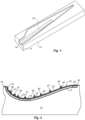
- FIG. 1 shows a schematic view of a mould part 13 for manufacturing one of the separate wind turbine blade shell parts.
- the wind turbine blade shell is manufactured as fibre-reinforced composite structures comprising a fibre-reinforcement material embedded in a polymer matrix.
- the blade shell parts 11 are manufactured separately by arranging the fibre-reinforcement material and typically also sandwich core material, such as foamed polymer or balsawood, on a mould surface 14 of the mould 13.
- the fibre reinforcement material is laid out as separate fibre mats that are stacked overlapping on the mould surface 14.
- the load bearing structure of the wind turbine blade may be manufactured as a spar cap 18 integrated in the blade shell, also called a main laminate, with shear webs arranged between the spar caps of the pressure side shell part and the suction side shell part.
- the load bearing structure may be formed as a spar or a beam, and the aerodynamic shell is adhered to the load bearing structure.
- the two blade shell parts are also glued to each other, e.g. by use of internal flange parts.
- the fibre mats may be laid up manually on the mould surface 14 or by use of a fibre mat layup system, in which case the fibre mats may be laid up automatically or semi-automatically.
- the rigid mould part 13 is provided with a mould surface 14 forming the outer surface of the shell half, i.e. the pressure side of the blade.
- Fig. 2 shows a cross-sectional view of the rigid mould part 13 for forming the shell part 11 of the wind turbine blade.
- the mould part 13 is provided with an upper rim 15, as clearly seen in Fig. 2 .
- a lay-up 16 comprising a number of fibre layers is placed on the mould surface 14.
- the fibre lay-up 16 comprises first fibre layers 17 arranged directly on the mould surface 14 or optionally with a previously applied gelcoat.
- a large number of fibre layers are placed in a longitudinally extending zone of the mould so as to provide a load-bearing structure (or spar cap) 18 of the blade shell half.
- the zone forming the load-bearing structure 18 is provided in the lowermost area of the mould surface.
- a plurality of fibre layers may be arranged on the first lower fibre layers 17 at a region corresponding to the region of the leading edge and the trailing edge, respectively, of the blade shell half to provide a leading edge fibre reinforcement 19 and a trailing edge fibre reinforcement 20.
- a first core material 21 may be arranged between the load-bearing structure 18 and the leading edge fibre reinforcement 19 and a second core material 22 may be arranged between the load-bearing structure 18 and the trailing edge fibre reinforcement 20.
- the core material can be a hard polymer foam or balsawood.
- the fibre lay-up 16 is completed by arranging second fibre layers 23 on top of the load-bearing structure 18, the leading edge fibre reinforcement 19, the trailing edge fibre reinforcement 20, the first core material 21 and the second core material 22. While the core materials 21, 22 are depicted as extending all the way between fibre reinforcements 18, 19, 20, the core materials 21, 22 may be arranged at a limited part of the blade shell only.
- a distribution layer 24 is arranged on the second fibre layers 23. Further, substantially longitudinally extending feed channels 36-42 are arranged above the fibre distribution layer 24 on either side of and laterally spaced apart from a longitudinally extending first feed channel 27 arranged above the load-bearing structure 18. Further, the additional feed channels 36-42 are placed laterally outside the load-bearing structure 18.
- a vacuum bag 43 is arranged on top of the distribution layer 24 and the feed channels and sealed to the rim 15 of the mould part to form a mould cavity 44 between the vacuum bag 43 and the mould surface 14 of the mould part 13. The mould cavity is then evacuated, and resin is supplied to the mould cavity via the feed channels 27, 36-42.
- the resin is allowed to cure in order to form the composite structure of the blade shell part 11, after which a debagging and demoulding process can be commenced in order to finalise the assembly of the wind turbine blade.
- the lay-up includes the arrangement of a peel ply, a release film, or a similar tear-off layer (not shown) on top of the inner fibre layers, e.g. arranged below the distribution layer 24.
- This peel ply or release film ensures that the infusion tools that do not become part of the composite structure can be removed in the debagging process.
- the infusion tools include the feed channels 27, 36-42, the tear-off layer, the vacuum bag as well as possible vacuum outlet channels.
- the infusion tools are in the following referred to by common reference number 50.
- debagging process is typically carried out manually, which is a tedious process, and which can entail unsafe conditions and acts.
- a new debagging tool has been developed.
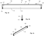
- a first embodiment of such a debagging tool 110 is illustrated in Figs. 3a-3c .
- the first embodiment of the debagging tool 110 comprises a support frame 120 for carrying a lifting bar 112 for lifting and carrying the infusion tools during the debagging process.
- the lifting bar may advantageously be provided in form of a roller or comprise a roller.
- the support frame 120 comprises a top frame part 122, a first side frame part 124 and a second side frame part 126.
- the support frame may further be enforced with gussets 127 or other reinforcement elements.
- the lifting bar 112 is attached at a first end to the first side frame part 124 via attachments means 116.
- the lifting bar 112 is attached at a second end to the second side frame part 126 via corresponding attachments means 116.
- the attachment means 116 may be formed for instance by bolts, nuts, and holding plates.
- the debagging tool 110 has two lifting ears 160 attached to the top frame part 122.
- the lifting ears 160 can be used for attaching the debagging tool 110 to an overhead crane or gantry via for instance chains and hooks.
- the infusion tools 50 are inserted in the space 170 formed between the lifting bar 112 and the support frame 120.
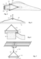
- Figs. 4-7 illustrate the debagging process by use of a debagging system that comprises the debagging tool 110 carried by conveying means 104 in form of an overhead crane or gantry using e.g. chains 102 in order to peel the infusion tools 50 from the cured wind turbine blade shell 11.
- a part of the removable infusion tools 50 is manually peeled from the cured wind turbine shell 11.
- the removable infusion tools are peeled from the root side of the mould 13 and wind turbine blade shell 11, after which the manually peeled part is loaded onto the space 170 between the lifting bar 112 and the support frame 120 of the debagging tool 110, which is best seen in the front view illustrated in Fig. 6 .
- the debagging tool 110 is moved along the mould part 13 using an overhead crane or gantry 104, thereby lifting the removable infusion tool from the cured blade shell part 11 and mould part 13.
- the end of the removable infusion tools 50 needs to be held in place, e.g. by clamping using clamping means 106, to manage the opposite pulling force from the debagging tool 110 and the conveying means, as the debagging tool 110 is moved along the mould part 13.
- the lifting bar 112 can be moved upwards and forwards, and this movement will peel the removable infusion tools 50 from the cured wind turbine blade shell 11.
- the debagging tool 110 can be carried by an overhead crane or gantry 104.
- the system 100 may use a crane or gantry being movable along tracks.
- the debagging tool 110 may be attached to the overhead crane or gantry via chains 102 and hooks.
- the system may be provided with a hoisting mechanism, such that the debagging tool 110 can be moved both up and down as well as along the longitudinal direction of the mould part 13, such that the required forces can be applied to the removable infusion tools in the debagging process.
- the lifting bar 112 is advantageously be provided in form of or comprising a roller, such that the debagging tool easier can be moved along the mould part 13 in the debagging process without being stuck or tearing the removable infusion tools 50.
- a second embodiment of a debagging tool 210 is shown in Figs. 8a-8e .
- the debagging tool 210 comprises a support frame 220 and a lifting bar 212 connected to the support frame for insertion under infusion tools 50 and lifting the infusion tools 50 during the debagging.
- the support frame 220 comprises a top frame part 222, a first side frame part 224, a second side frame part 226, and a bottom frame part 228.
- a first end of the lifting bar 212 is coupled to the first side frame part 224, and a second end of the lifting bar 212 is coupled to the second side frame part 226.
- the support frame 220 may further be enforced with gussets 227 or other reinforcement elements.
- the lifting bar 212 may comprise a first roller or be provided as a first roller.
- the first roller may be connected to a first drive or first motor 214 for driving the first roller.
- the first roller can actively be used for asserting a force to the infusion tools and assist in peeling the infusion tools 50 from the finished moulded structure.
- the first roller may advantageously be configured to be driven in both a first direction and a second, opposite direction. Accordingly, the first roller may be used for both asserting a force in a first direction and a second direction. Thereby, the first roller can also be used for first peeling the infusions tools 50 from the finished moulded structure 14 and later removing the infusion tools 50 from the mould part 13.
- a surface of the first roller may advantageously be provided with gripping means, e.g., by providing a rough surface or a ridged, fluted, or grooved surface.
- gripping means e.g., by providing a rough surface or a ridged, fluted, or grooved surface.
- the debagging tool 210 may further comprises one or more upper support rollers 230 configured to engage with the infusion tools when lifted by the lifting bar 212.
- the one or more upper support rollers are coupled to the support frame with a first end coupled to the first side frame part 224 and a second end coupled to the second side frame part 226. This will contribute to guide the infusion tools more efficiently over the lifting bar and may further contribute to asserting a gripping or clamping force on the infusion tools, whereby a pulling force more efficiently can be asserted to the infusion tools.
- the one or more upper support rollers 230 may also provide with gripping means, e.g., by providing a rough surface or a ridged, fluted, or grooved surface.
- the one or more upper support rollers 230 are preferably connected to one or more second drives or second motors 232 for driving the one or more upper support rollers 230.
- the one or more upper support rollers 230 can also or alternatively be used to assert the pulling force to the infusion tools 50.
- the one or more are configured to be driven in both a first direction and a second, opposite direction.
- the debagging tool 210 When the first roller 212 and the one or more upper support rollers 230 are both connected to drives or motors, the debagging tool 210 will have the further advantage of having a built-in redundancy in case one of the drives or motors fail.
- the infusion tools 50 are inserted in the space 270 formed between the lifting bar 212 and the one or more upper rollers 230.
- the one or more upper support rollers 230 are preferably as shown in Fig. 8 arranged and configured to be height adjusted relative to the support frame. Thereby, the one or more upper support rollers 230 are also height adjustable relative to the lifting bar 230. This provides a simple solution for engaging the infusion tools 50.
- the one or more upper support rollers may for instance as shown be height adjustable by one or more motors 250 attached to the support frame 220.
- the motor(s) 250 can be connected to a spindle or the like, which in turn is attached to frames carrying the one or more upper support rollers 230 as well as the second motor 232.
- the one or more upper support rollers 230 may be guided along slots 254 formed in the first side frame part 224 and second side frame part 226.
- the support frame 220 preferably comprises attachment means 260, such as attachment ears, for attaching the debagging tool 210 to the conveying means 102.
- attachment means 260 such as attachment ears
- This provides simple means for attaching the debagging tool 210 to for instance an overhead crane or a gantry configured to move along the mould part 13. Accordingly, it is seen that the second embodiment of the debagging tool 210 may be suspended from the conveying means in a way similar to that of the first embodiment of the debagging tool 110 and as shown in Figs. 4-7 .
- one or more lower support rollers 240 are mounted on the lower frame part 228 and arranged and configured to support the lifting bar 212.
- This provides a simple solution for adding support to the lifting bar 212, e.g., the first roller, on the support frame 220.
- the one or more lower support rollers 240 may be arranged on a frame 242 mounted on the lower frame part 228 of the support frame 220.
- the second embodiment of the debagging tool 210 can be suspended and operated in a way similar to those shown in Figs. 4-7 .
- the second embodiment has the advantage of better asserting a pulling or peeling force to the infusion tools 50 during the debagging process.
- the debagging system 100 may be configured to provide a pulling force F in a direction that forms an angle ⁇ of 30-60 degrees compared to a mould surface of the mould part 13. Equivalently, the pulling force direction may be 30-60 degrees compared to a horizontal plane, e.g., the factory floor. The direction of the pulling force may be provided by the height at which the debagging tool 210' is moved along the mould.
- the debagging system should be configured and operational to convey the debagging tool 210' along the mould at a height above the mould surface to provide a pulling force within this angle interval.
- the speed with which the debagging tool is moved along the mould and the speed of the roller or rollers 212', 230' that assert the pulling force can also attribute to achieving the desired pulling angle.
- the debagging system 100 or the debagging tool 210 may provided with a tilt sensor to monitor the inclination or tilt of the debagging tools relative to a mould surface of the mould.
- the tilt sensor may be provided in form of an inclinometer, accelerometers, gyros, or the like. This ensures that the debagging tool may be maintained in an acceptable orientation relative to the surface of the mould and in turn ensure that the correct pulling force and direction may be maintained.
- the debagging system may be configured to maintain the debagging tool at a tilt angle being below a threshold angle compared to a vertical plane, preferably the system being configured to keep the tilt angle below 5 or even below 3 degrees, more preferably below 2 degrees, and even more preferably below 1.5 degrees.
- the angle can be based for instance on a longitudinal axis 275 extending through the debagging tool 210 as shown in Fig. 8a .
- the debagging system further comprises a cutting device (not shown) for cutting the infusion tools to divide the infusion tools into separate disposable parts. Accordingly, the infusion tools may be divided into smaller parts as it is removed from the mould.
- the system may additionally comprise a container for collecting the separate disposable parts.
- the width of the lifting bar may advantageously be at least 3 metres, preferably at least 3.5 metres, and more preferably at least 4 metres.
- the lifting bar and the system should have a width so that it can be used for debagging the infusion tools at the place where the mould and moulded structure is widest.
- this position is the position, where the wind turbine blade is to have the widest chord, e.g., at the shoulder of the wind turbine blade.
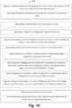
- Fig. 10 shows a method 300 for debagging infusion tools during the manufacture of a wind turbine blade part in a mould for manufacturing the wind turbine blade part.
- a first part of the infusion tools is peeled manually from the wind turbine blade part.
- the first part may for instance be peeled from a root side or tip side of the mould.
- the lifting bar is then inserted under the infusion tools at the manually peeled first part in step 307 and a longitudinal end of the infusion tools is clamped to the mould part in step 306.
- the debagging tool is then in step 310 moved along a longitudinal direction of the mould in order for the lifting bar to peel the infusion tools from the finished wind turbine blade part.
- a peeling for may be provided to the infusion tools, for instance via one or more rollers as shown in step 312.
- the peeling force may be provided in a direction that forms an angle of 30-60 degrees compared to a mould surface of the mould or alternatively a horizontal surface as shown in step 314.
- the debagging tools may as shown in step 316 be maintained at a tilt angle below a threshold angle compared to a vertical plane, preferably keeping the tilt angle below 4 degrees or even below 3 degrees, more preferably below 2 degrees, and even more preferably below 1.5 degrees
- the debagging tool may be operated to maintain the peeling force in a first direction, while the debagging tool is moved along the longitudinal direction, and when reaching a removal position, e.g., at one of longitudinal ends of the mould, the debagging tool is in step 320 operated to provide a force in a second direction to start removing the infusion tools from the mould.
- the infusion tools are then in step 322 removed from the mould.
- the infusion tools may be cut in to divide the infusion tools into separate disposable parts, which can be collected in a container to easier dispose of the disposable infusion tools.
- Fig 11 shows a method 400 of manufacturing a wind turbine blade part, e.g., a wind turbine blade shell or a spar cap.
- a mould for manufacturing the wind turbine blade part is provided.
- fibre reinforcement material is arranged on a mould surface of the mould.
- infusion tools are arranged on top of the fibre reinforcement material, where the infusion tools comprise at least a vacuum bag.
- the vacuum bag is sealed against the mould to form a mould cavity.
- resin is supplied into the mould cavity.
- step 412 the resin is cured to form the wind turbine blade part.
- the aforementioned debagging method 300 is carried out in order to remove the infusion tools from the finished wind turbine blade part.
Landscapes
- Engineering & Computer Science (AREA)
- Mechanical Engineering (AREA)
- Chemical & Material Sciences (AREA)
- Composite Materials (AREA)
- Moulding By Coating Moulds (AREA)
- Wind Motors (AREA)
- Structures Of Non-Positive Displacement Pumps (AREA)
- Casting Or Compression Moulding Of Plastics Or The Like (AREA)
Abstract
Description
- The present invention relates to a debagging system for use in a debagging process during the manufacture of a wind turbine blade. The invention also relates to a debagging tool that is part of the debagging system. Further, the invention relates to a method for debagging infusion tools during the manufacture of a wind turbine blade part in a mould for manufacturing the wind turbine blade part. Finally, the invention relates to a method of manufacturing a wind turbine blade part, which involves the debagging method.
- Wind turbine blades are often manufactured according to one of two constructional designs, namely a design where a thin aerodynamic shell is glued onto a spar beam, or a design where spar caps, also called main laminates, are integrated into the aerodynamic shell.
- In the first design, the spar beam constitutes the load bearing structure of the blade. The spar beam as well as the aerodynamic shell or shell parts are manufactured separately. The aerodynamic shell is often manufactured as two shell parts, typically as a pressure side shell part and a suction side shell part. The two shell parts are glued or otherwise connected to the spar beam and are further glued to each other along a leading edge and a trailing edge of the shell parts. This design has the advantage that the critical load carrying structure may be manufactured separately and therefore easier to control. Further, this design allows for various different manufacturing methods for producing the beam, such as moulding and filament winding.
- In the second design, the spar caps or main laminates are integrated into the shell and are moulded together with the aerodynamic shell. The main laminates typically comprise a high number of fibre layers compared to the remainder of the blade and may form a local thickening of the wind turbine shell, at least with respect to the number of fibre layers. Thus, the main laminate may form a fibre insertion in the blade. In this design, the main laminates constitute the load carrying structure. The blade shells are typically designed with a first main laminate integrated in the pressure side shell part and a second main laminate integrated in the suction side shell part. The first main laminate and the second main laminate are typically connected via one or more shear webs, which for instance may be C-shaped or I-shaped. For very long blades, the blade shells further along at least a part of the longitudinal extent comprise an additional first main laminate in the pressure side shell, and an additional second main laminate in the suction side shell. These additional main laminates may also be connected via one or more shear webs. This design has the advantage that it is easier to control the aerodynamic shape of the blade via the moulding of the blade shell part.
- Vacuum infusion or VARTM (vacuum assisted resin transfer moulding) is one method, which is typically employed for manufacturing composite structures, such as wind turbine blades comprising a fibre reinforced matrix material.
- During the process of filling the mould, a vacuum, said vacuum in this connection being understood as an under-pressure or negative pressure, is generated via vacuum outlets in the mould cavity, whereby liquid polymer is drawn into the mould cavity via the inlet channels in order to fill said mould cavity. From the inlet channels the polymer disperses in all directions in the mould cavity due to the negative pressure as a flow front moves towards the vacuum channels. Thus, it is important to position the inlet channels and vacuum channels optimally in order to obtain a complete filling of the mould cavity.
- In most cases the polymer or resin applied is polyester, vinyl ester or epoxy, but may also be PUR or pDCPD, and the fibre reinforcement is most often based on glass fibres, carbon fibres, or a mixture hereof. Epoxies have advantages with respect to various properties, such as shrinkage during curing (which in some circumstances may lead to less wrinkles in the laminate), electrical properties and mechanical and fatigue strengths. Polyester and vinyl esters have the advantage that they provide better bonding properties to gelcoats. Thereby, a gelcoat may be applied to the outer surface of the shell during the manufacturing of the shell by applying a gelcoat to the mould before fibre-reinforcement material is arranged in the mould. Thus, various post-moulding operations, such as painting the blade, may be avoided. Further, polyesters and vinyl esters are cheaper than epoxies. Consequently, the manufacturing process may be simplified, and costs may be lowered.
- Often the composite structures comprise a core material covered with a fibre reinforced material, such as one or more fibre reinforced polymer layers. The core material can be used as a spacer between such layers to form a sandwich structure and is typically made of a rigid, lightweight material in order to reduce the weight of the composite structure. In order to ensure an efficient distribution of the liquid resin during the impregnation process, the core material may be provided with a resin distribution network, for instance by providing channels or grooves in the surface of the core material.
- Resin transfer moulding (RTM) is a manufacturing method, which is similar to VARTM. In RTM the liquid resin is not drawn into the mould cavity due to a vacuum generated in the mould cavity. Instead, the liquid resin is forced into the mould cavity via an overpressure at the inlet side.
- Prepreg moulding is a method in which reinforcement fibres are pre-impregnated with a pre-catalysed resin. The resin is typically solid or near-solid at room temperature. The prepregs are arranged by hand or machine onto a mould surface, vacuum bagged and then heated to a temperature, where the resin is allowed to reflow and eventually cure. This method has the main advantage that the resin content in the fibre material is accurately set beforehand. The prepregs are easy and clean to work with and make automation and labour saving feasible. The disadvantage with prepregs is that the material cost is higher than for non-impregnated fibres. Further, the core material needs to be made of a material, which is able to withstand the process temperatures needed for bringing the resin to reflow. Prepreg moulding may be used both in connection with an RTM and a VARTM process.
- Further, it is possible to manufacture hollow mouldings in one piece by use of outer mould parts and a mould core. Such a method is for instance described in
EP 1 310 351 and may readily be combined with RTM, VARTM and prepreg moulding. - Common for the various moulding techniques is that a number of tools are arranged on top of the mould and the material that is to be infused with resin and that needs to be removed after the resin has cured in order to form the composite structure of the wind turbine blade. Such tools include resin inlets, vacuum outlets, vacuum bag, and other infusion media. These tools are often arranged on top of a peel ply, a release film, or a similar tear-off layer, which in turn is arranged on top of the material arranged in the mould cavity, such that all tools can be removed together from the composite structure after the resin has cured. This process is often called the debagging process. Afterwards, required post-moulding operations can be carried out.
- The debagging process is typically carried out manually, which is a tedious process, and which can entail unsafe conditions and acts. The tools are quite heavy, and it requires strength to manually remove the tools. In addition, it may not be possible to remove all tools at once. Instead, the vacuum bag may have to be removed first, then the release film or peel ply together with the resin inlets, vacuum outlets, and other infusion tools. Often 7-10 workers are involved in removing the tools, which may even require the workers to stand on the manufactured structure, e.g. the wind turbine blade shell, which in turn may introduce mechanical defects to the structure. Further, the workers face several potential hazards and ergonomic issues, such as risks of slipping, knee pain, strain to the hand, fingers, or back, and so forth.
- Accordingly, there is a need for new tools and methods for use in the debagging process.
- It is an object of the invention to obtain a method, system, and tool, which overcome or ameliorate at least one of the disadvantages of the prior art or which provide a useful alternative.
- According to a first aspect, there is provided a debagging system for use in a debagging process during the manufacture of a wind turbine blade, wherein the debagging system comprises: a debagging tool, and conveying means configured to move the debagging tool along a longitudinal direction of a mould for manufacturing a wind turbine blade part. The debagging tool comprises: a lifting bar for insertion under infusion tools and lifting the infusion tools during the debagging process, the lifting bar having a first end and a second end, and a support frame for carrying the lifting bar, wherein the lifting bar is coupled to the support frame, and wherein the debagging tool is suspended from the conveying means so that the debagging tool during use can be arranged above the mould and be moved along the longitudinal direction of the mould.
- According to a second aspect, there is provided a debagging tool for use in a debagging process during the manufacture of a wind turbine blade, wherein the debagging tool comprises: a lifting bar for insertion under infusion tools and lifting the infusion tools during the debagging process, the lifting bar having a first end and a second end, and a support frame for carrying the lifting bar, wherein the lifting bar is coupled to the support frame.
- According to a third aspect, there is provided a method for debagging infusion tools during the manufacture of a wind turbine blade part in a mould for manufacturing the wind turbine blade part, wherein the method comprises the steps of: inserting a lifting bar of a debagging tool under the infusion tools; moving the debagging tool along a longitudinal direction of the mould in order for the lifting bar to peel the infusion tools from the wind turbine blade part; and removing the infusion tools from the mould.
- According to a fourth aspect, there is provided a method of manufacturing a wind turbine blade part, e.g., a wind turbine blade shell or a spar cap, wherein the method comprises the steps of: proving a mould for manufacturing the wind turbine blade part; arranging fibre reinforcement material on a mould surface of the mould; arranging infusion tools on top of the fibre reinforcement material, the infusion tools comprising a vacuum bag; sealing the vacuum bag against the mould to form a mould cavity; supplying resin into the mould cavity; curing the resin to form the wind turbine blade part; and carrying out a debagging process according to the third aspect.
- Thereby, a simple debagging system and debagging tool are provided that can be utilised to be moved along a mould for manufacturing e.g., a wind turbine blade shell part and peel the infusion tools from the finished moulded structure, such as a wind turbine blade shell. This can ameliorate or at least decrease the need for manual work in the debagging process and may further speed up the debagging process. Similarly, the method for debagging infusion tools during the manufacture of a wind turbine blade part may reduce the need for manual work in the debagging process.
- In the following, there is referred to infusion tools. But in general, it is understood that the specification refers to the disposable tools that are used in the infusion process and that do not become part of the product.
- Further, the wind turbine blade part is preferably a wind turbine blade shell part, such as an upwind or downwind wind turbine blade shell, alternatively a spar cap for the wind turbine blade.
- In the following, advantageous and preferred embodiments are described which can be utilised with any of the first, second, third, and fourth aspect.
- According to a preferred embodiment, the lifting bar comprises a first roller. Thereby, the debagging tool can more easily be moved along the mould and used for the debagging process, because the first roller rotates as the debagging tool is moved along the mould and debagging tools. Preferably, the first roller is connected to a first drive or motor for driving the first roller. Thus, the roller can actively be used for asserting a force to the infusion tools and assist in peeling the infusion tools from the finished moulded structure. The first roller may advantageously be configured to be driven in both a first direction and a second, opposite direction. Accordingly, the first roller may be used for both asserting a force in a first direction and a second direction. Thereby, the first roller can also be used for first peeling the infusion tools from the finished moulded structure and later removing the infusion tools from the mould. A surface of the first roller may advantageously be provided with gripping means, e.g., by providing a rough surface or a ridged, fluted, or grooved surface. Thereby, the roller can add grip to the engagement with the infusion tools, which in turn assist in asserting the peeling force to the infusion tools.
- According to a preferred embodiment, the lifting bar is coupled to the support frame at the first end and at the second end of the lifting bar. This provides a simple solution for carrying the lifting bar and making sure that the infusion tools can fit over the lifting bar.
- The support frame preferably comprises attachment means, such as attachment ears, for attaching the debagging tool to conveying means, such as an overhead crane or a gantry. This provides simple means for attaching the debagging tool to for instance an overhead crane or a gantry configured to move along the mould.
- According to a preferred embodiment, the support frame comprises a top frame part and a first side frame part and a second side frame part, wherein the first side frame part and second side frame part extend from the top frame part, and wherein the first end of the lifting bar is coupled to the first side frame part, and the second end of the lifting bar is coupled to the second side frame part. This provides a simple solution for attaching the lifting bar (e.g., the first roller) to the support frame and ensuring that the width of the infusion tools can be inserted over the lifting bar in a space formed by at least the lifting bar, the two side frames and the top frame.
- In one preferred embodiment, the debagging tool further comprises one or more upper support rollers configured to engage with the infusion tools when lifted by the lifting bar, wherein the one or more upper support rollers are coupled to the support frame. This will contribute to guide the infusion tools more efficiently over the lifting bar and may further contribute to asserting a gripping or clamping force on the infusion tools, whereby a pulling force more efficiently can be asserted to the infusion tools. The one or more upper support rollers may also provide with gripping means, e.g., by providing a rough surface or a ridged, fluted, or grooved surface. Preferably, the one or more upper support rollers are arranged and configured to be height adjusted relative to the support frame. Thereby, the one or more upper support rollers are also height adjustable relative to the lifting bar. This provides a simple solution for engaging the infusion tools. The one or more upper support rollers may for instance be height adjustable by one or more motors attached to the support frame and/or by use of spring forces. The height adjustment may also utilise a telescoping arrangement for carrying the one or more upper support rollers. Advantageously, the one or more upper support rollers are connected to one or more second drives or motors for driving the one or more upper support rollers. Thereby, the one or more upper support rollers can also or alternatively be used to assert the pulling force to the infusion tools. Preferably, the one or more are configured to be driven in both a first direction and a second, opposite direction.
- According to a preferred embodiment, both the first roller and the one or more upper support rollers are connected to drives or motors. Thereby, the debagging tool will have a built-in redundancy in case one of the drives or motors fail.
- In an advantageous embodiment, the support frame further comprises a lower frame part. Preferably, it extends between the first side frame part and the second side frame part, and maybe arranged and configured to support the lifting bar. In a preferred embodiment, one or more lower support rollers, such as idler rollers, are mounted on the lower frame part and arranged and configured to support the lifting bar. This provides a simple solution for adding support to the lifting bar, e.g., the first roller, on the support frame.
- Advantageously, the width of the lifting bar is at least 3 metres, preferably at least 3.5 metres, and more preferably at least 4 metres. In general, the lifting bar and the system should have a width so that it can be used for debagging the infusion tools at the place where the mould and moulded structure is widest. For a wind turbine blade shell part, this position is the position, where the wind turbine blade is to have the widest chord, e.g., at the shoulder of the wind turbine blade.
- In a preferred embodiment, the conveying means comprise an overhead crane or gantry. An overhead crane from the factory may for instance be used. However, it is also possible to use a separate gantry that can be moved along the mould. It may for instance be possible to use the fibre material wagon or gantry that can be used for laying up fibre material in the mould. The debagging tool may be a separate module that can be attached to the overhead crane or the fibre material wagon, e.g., replacing a layup head.
- In a preferred embodiment, the debagging system is configured to provide a pulling force in a direction that forms an angle of 30-60 degrees compared to a mould surface of the mould. Equivalently, the pulling force direction may be 30-60 degrees compared to a horizontal plane, e.g., the factory floor. The direction of the pulling force may be provided by the height at which the debagging tool is moved along the mould. Accordingly, the debagging system should be configured and operational to convey the debagging tool along the mould at a height above the mould surface to provide a pulling force within this angle interval. The speed with which the debagging tool is moved along the mould and the speed of the roller or rollers that assert the pulling force can also attribute to achieving the desired pulling angle.
- In an advantageous embodiment, the debagging system is provided with a tilt sensor to monitor the inclination or tilt of the debagging tools relative to a mould surface of the mould. Equivalently, the tilt sensor may be configured to measure the tilt angle of the debagging tool relative to a vertical plane. The tilt angle may for instance be compared to a central axis through the debagging tool. The tilt sensor may be provided in form of an inclinometer, accelerometers, gyros, or the like. This ensures that the debagging tool may be maintained in an acceptable orientation relative to the surface of the mould and in turn ensure that the correct pulling force and direction may be maintained. The debagging system may be configured to maintain the debagging tool at a tilt angle being below a threshold angle compared to a vertical plane, preferably the system being configured to keep the tilt angle below 5 degrees or even below 3 degrees, more preferably below 2 degrees, and even more preferably below 1.5 degrees.
- The system may be configured to provide an alarm if the threshold angle is exceeded. The system may also be provided with a feedback system that ensures that the system is maintained below the threshold value, e.g. by lowering the speed of conveying or the speed of the motor.
- Similar systems can be implemented to monitor other parameter, such as the rotation angle of the tool relative to a transverse plane of the mould.
- The debagging system preferably further comprises a clamping device for clamping a part, preferably an end part, of the infusion tools to the mould. Thereby, the clamping device may assert a clamping force to retain for instance an end of the infusion tools during the debagging process, such that a peeling force more easily can be asserted to the infusion tools.
- In another embodiment, the debagging system further comprises a cutting device for cutting the infusion tools to divide the infusion tools into separate disposable parts. Accordingly, the infusion tools may de divided into smaller parts as it is removed from the mould. The system may additionally comprise a container for collecting the separate disposable parts.
- The aforementioned method may preferably comprise the step of: prior to inserting the lifting bar of the debagging tool under the infusion tools, peeling a first part of the infusion tools from the wind turbine blade part. This ensures that the lifting bar may be inserted under the infusion tools. Preferably, the first part of the infusion tools is peeled from a root side or a tip side of the mould.
- The method may include clamping a longitudinal end of the infusion tools to the mould, e.g., at tip end or root end, and preferably at the first part that has been manually peeled from the finished wind turbine blade part. Thus, a clamping force can be asserted whereby a pulling force more efficiently can be asserted to the infusion tools.
- The method preferably includes providing peeling force to the infusion tools, e.g., via one or more rollers and drives. It is clear that the lifting bar may be one of the one or more rollers. It is also clear that the debagging system may be operated so as to provide the peeling force. The peeling force may advantageously be provided in a direction that forms an angle of 30-60 degrees compared to a mould surface of the mould.
- In a preferred embodiment, the debagging tool is operated to maintain the peeling force in a first direction, while the debagging tool is moved along the longitudinal direction, and when reaching a removal position, e.g., at one of the longitudinal ends of the mould, the debagging tool is operated to provide a force in a second direction to start removing the infusion tools from the mould. The second direction is preferably substantially opposite the first direction. Thereby, the debagging tool can first be used for peeling the infusion tools from the wind turbine blade part and then later for removing the infusion tools from the wind turbine blade part and the mould.
- In another embodiment, the method includes: while removing the infusion tools from the mould, cutting the infusion tools to divide the infusion tools into separate disposable parts. Thereby, the infusion tools are easier to dispose. The separate disposable parts may be collected in a container.
- In yet another embodiment, the method comprises the step of: maintaining the debagging tool at a tilt angle below a threshold angle compared to a vertical plane, preferably keeping the tilt angle below 5 degrees or even 3 degrees, more preferably below 2 degrees, and even more preferably below 1.5 degrees.
- The invention is explained in detail below with reference to embodiments shown in the drawings, in which
-
Fig. 1 shows a schematic view of a wind turbine blade mould for moulding a wind turbine blade shell part, -
Fig. 2 shows a schematic cross-sectional view through a mould for moulding wind turbine blade shell part, -
Figs. 3a-3c show a front view, a side view, and a perspective view of a first embodiment of a debagging tool, -
Fig. 4 illustrates a top view of a debagging tool being along a mould for moulding a wind turbine blade shell part during a debagging process, -
Fig. 5 illustrates a side view of a debagging tool being along a mould for moulding a wind turbine blade shell part during a debagging process, -
Fig. 6 illustrates a front view of a debagging tool being along a mould for moulding a wind turbine blade shell part during a debagging process, -
Fig. 7 illustrates conveying means for use with the debagging tool in a debagging system, -
Figs. 8a-8e show a first side view, a front view, a second side view, a top view, and a perspective view of a second embodiment of a debagging tool, -
Fig. 9 illustrates a debagging tool asserting a peeling force to infusion tools, -
Fig. 10 illustrates the steps used a method for debagging infusion tools during the manufacture of a wind turbine blade part in a mould for manufacturing the wind turbine blade part, and -
Fig. 11 illustrates the steps used in a method of manufacturing a wind turbine blade part. - In the following, a number of exemplary embodiments are described in order to understand the invention.
- Modern wind turbine blades comprise an aerodynamic shell, and the suction side and the pressure side of the aerodynamic shell are often manufactured as separate parts in separate moulds.
Fig. 1 shows a schematic view of amould part 13 for manufacturing one of the separate wind turbine blade shell parts. The wind turbine blade shell is manufactured as fibre-reinforced composite structures comprising a fibre-reinforcement material embedded in a polymer matrix. Theblade shell parts 11 are manufactured separately by arranging the fibre-reinforcement material and typically also sandwich core material, such as foamed polymer or balsawood, on amould surface 14 of themould 13. The fibre reinforcement material is laid out as separate fibre mats that are stacked overlapping on themould surface 14. The load bearing structure of the wind turbine blade may be manufactured as aspar cap 18 integrated in the blade shell, also called a main laminate, with shear webs arranged between the spar caps of the pressure side shell part and the suction side shell part. Alternatively, the load bearing structure may be formed as a spar or a beam, and the aerodynamic shell is adhered to the load bearing structure. The two blade shell parts are also glued to each other, e.g. by use of internal flange parts. The fibre mats may be laid up manually on themould surface 14 or by use of a fibre mat layup system, in which case the fibre mats may be laid up automatically or semi-automatically. - For manufacturing the
blade shell half 11, therigid mould part 13 is provided with amould surface 14 forming the outer surface of the shell half, i.e. the pressure side of the blade.Fig. 2 shows a cross-sectional view of therigid mould part 13 for forming theshell part 11 of the wind turbine blade. - In the following, an example of the lay-up and tools used for manufacturing the
blade shell part 11 is described. Themould part 13 is provided with anupper rim 15, as clearly seen inFig. 2 . - A lay-
up 16 comprising a number of fibre layers is placed on themould surface 14. In the embodiment shown, the fibre lay-up 16 comprises first fibre layers 17 arranged directly on themould surface 14 or optionally with a previously applied gelcoat. On the first fibre layers, a large number of fibre layers are placed in a longitudinally extending zone of the mould so as to provide a load-bearing structure (or spar cap) 18 of the blade shell half. As seen in the transverse direction of the mould, the zone forming the load-bearing structure 18 is provided in the lowermost area of the mould surface. Additionally, a plurality of fibre layers may be arranged on the first lower fibre layers 17 at a region corresponding to the region of the leading edge and the trailing edge, respectively, of the blade shell half to provide a leadingedge fibre reinforcement 19 and a trailingedge fibre reinforcement 20. Afirst core material 21 may be arranged between the load-bearing structure 18 and the leadingedge fibre reinforcement 19 and asecond core material 22 may be arranged between the load-bearing structure 18 and the trailingedge fibre reinforcement 20. The core material can be a hard polymer foam or balsawood. The fibre lay-up 16 is completed by arranging second fibre layers 23 on top of the load-bearing structure 18, the leadingedge fibre reinforcement 19, the trailingedge fibre reinforcement 20, thefirst core material 21 and thesecond core material 22. While thecore materials fibre reinforcements core materials - Next, a
distribution layer 24 is arranged on the second fibre layers 23. Further, substantially longitudinally extending feed channels 36-42 are arranged above thefibre distribution layer 24 on either side of and laterally spaced apart from a longitudinally extendingfirst feed channel 27 arranged above the load-bearing structure 18. Further, the additional feed channels 36-42 are placed laterally outside the load-bearing structure 18. Avacuum bag 43 is arranged on top of thedistribution layer 24 and the feed channels and sealed to therim 15 of the mould part to form amould cavity 44 between thevacuum bag 43 and themould surface 14 of themould part 13. The mould cavity is then evacuated, and resin is supplied to the mould cavity via thefeed channels 27, 36-42. - Finally, the resin is allowed to cure in order to form the composite structure of the
blade shell part 11, after which a debagging and demoulding process can be commenced in order to finalise the assembly of the wind turbine blade. - The lay-up includes the arrangement of a peel ply, a release film, or a similar tear-off layer (not shown) on top of the inner fibre layers, e.g. arranged below the
distribution layer 24. This peel ply or release film ensures that the infusion tools that do not become part of the composite structure can be removed in the debagging process. The infusion tools include thefeed channels 27, 36-42, the tear-off layer, the vacuum bag as well as possible vacuum outlet channels. The infusion tools are in the following referred to bycommon reference number 50. - The debagging process is typically carried out manually, which is a tedious process, and which can entail unsafe conditions and acts. In order to address these problems, a new debagging tool has been developed. A first embodiment of such a
debagging tool 110 is illustrated inFigs. 3a-3c . - The first embodiment of the
debagging tool 110 comprises asupport frame 120 for carrying a liftingbar 112 for lifting and carrying the infusion tools during the debagging process. The lifting bar may advantageously be provided in form of a roller or comprise a roller. Thesupport frame 120 comprises atop frame part 122, a firstside frame part 124 and a secondside frame part 126. The support frame may further be enforced withgussets 127 or other reinforcement elements. The liftingbar 112 is attached at a first end to the firstside frame part 124 via attachments means 116. Similarly, the liftingbar 112 is attached at a second end to the secondside frame part 126 via corresponding attachments means 116. The attachment means 116 may be formed for instance by bolts, nuts, and holding plates. In addition, thedebagging tool 110 has two liftingears 160 attached to thetop frame part 122. The liftingears 160 can be used for attaching thedebagging tool 110 to an overhead crane or gantry via for instance chains and hooks. During the debagging process, theinfusion tools 50 are inserted in thespace 170 formed between the liftingbar 112 and thesupport frame 120. -
Figs. 4-7 illustrate the debagging process by use of a debagging system that comprises thedebagging tool 110 carried by conveying means 104 in form of an overhead crane or gantry usinge.g. chains 102 in order to peel theinfusion tools 50 from the cured windturbine blade shell 11. - In the initial phase of the debagging process, a part of the
removable infusion tools 50 is manually peeled from the curedwind turbine shell 11. As shown in the top view inFig. 4 , the removable infusion tools are peeled from the root side of themould 13 and windturbine blade shell 11, after which the manually peeled part is loaded onto thespace 170 between the liftingbar 112 and thesupport frame 120 of thedebagging tool 110, which is best seen in the front view illustrated inFig. 6 . Subsequently, thedebagging tool 110 is moved along themould part 13 using an overhead crane or gantry 104, thereby lifting the removable infusion tool from the curedblade shell part 11 andmould part 13. - The end of the
removable infusion tools 50 needs to be held in place, e.g. by clamping using clamping means 106, to manage the opposite pulling force from thedebagging tool 110 and the conveying means, as thedebagging tool 110 is moved along themould part 13. - In
Fig. 4 , the manually peeled part of theremovable infusion tools 50 is peeled from the root-side of themould part 13, and theremovable infusion tools 50 are held or clamped at the root-side of themould part 13. However, it is clear that this can alternatively be carried out at the tip-side of themould part 13. - As shown in
Fig. 5 , the liftingbar 112 can be moved upwards and forwards, and this movement will peel theremovable infusion tools 50 from the cured windturbine blade shell 11. - As shown in
Fig. 7 , thedebagging tool 110 can be carried by an overhead crane or gantry 104. As illustrated, thesystem 100 may use a crane or gantry being movable along tracks. As further shown, thedebagging tool 110 may be attached to the overhead crane or gantry viachains 102 and hooks. Further, the system may be provided with a hoisting mechanism, such that thedebagging tool 110 can be moved both up and down as well as along the longitudinal direction of themould part 13, such that the required forces can be applied to the removable infusion tools in the debagging process. - As shown, the lifting
bar 112 is advantageously be provided in form of or comprising a roller, such that the debagging tool easier can be moved along themould part 13 in the debagging process without being stuck or tearing theremovable infusion tools 50. - A second embodiment of a
debagging tool 210 is shown inFigs. 8a-8e . Thedebagging tool 210 comprises asupport frame 220 and a liftingbar 212 connected to the support frame for insertion underinfusion tools 50 and lifting theinfusion tools 50 during the debagging. Thesupport frame 220 comprises atop frame part 222, a firstside frame part 224, a secondside frame part 226, and abottom frame part 228. A first end of the liftingbar 212 is coupled to the firstside frame part 224, and a second end of the liftingbar 212 is coupled to the secondside frame part 226. Thesupport frame 220 may further be enforced withgussets 227 or other reinforcement elements. - The lifting
bar 212 may comprise a first roller or be provided as a first roller. The first roller may be connected to a first drive orfirst motor 214 for driving the first roller. Thus, the first roller can actively be used for asserting a force to the infusion tools and assist in peeling theinfusion tools 50 from the finished moulded structure. The first roller may advantageously be configured to be driven in both a first direction and a second, opposite direction. Accordingly, the first roller may be used for both asserting a force in a first direction and a second direction. Thereby, the first roller can also be used for first peeling theinfusions tools 50 from the finished mouldedstructure 14 and later removing theinfusion tools 50 from themould part 13. A surface of the first roller may advantageously be provided with gripping means, e.g., by providing a rough surface or a ridged, fluted, or grooved surface. Thereby, the roller can add grip to the engagement with the infusion tools, which in turn assist in asserting the peeling force to the infusion tools. - As shown in
Figs. 8b and 8e , thedebagging tool 210 may further comprises one or moreupper support rollers 230 configured to engage with the infusion tools when lifted by the liftingbar 212. The one or more upper support rollers are coupled to the support frame with a first end coupled to the firstside frame part 224 and a second end coupled to the secondside frame part 226. This will contribute to guide the infusion tools more efficiently over the lifting bar and may further contribute to asserting a gripping or clamping force on the infusion tools, whereby a pulling force more efficiently can be asserted to the infusion tools. The one or moreupper support rollers 230 may also provide with gripping means, e.g., by providing a rough surface or a ridged, fluted, or grooved surface. The one or moreupper support rollers 230 are preferably connected to one or more second drives orsecond motors 232 for driving the one or moreupper support rollers 230. Thereby, the one or moreupper support rollers 230 can also or alternatively be used to assert the pulling force to theinfusion tools 50. Preferably the one or more are configured to be driven in both a first direction and a second, opposite direction. When thefirst roller 212 and the one or moreupper support rollers 230 are both connected to drives or motors, thedebagging tool 210 will have the further advantage of having a built-in redundancy in case one of the drives or motors fail. Theinfusion tools 50 are inserted in thespace 270 formed between the liftingbar 212 and the one or moreupper rollers 230. - The one or more
upper support rollers 230 are preferably as shown inFig. 8 arranged and configured to be height adjusted relative to the support frame. Thereby, the one or moreupper support rollers 230 are also height adjustable relative to the liftingbar 230. This provides a simple solution for engaging theinfusion tools 50. The one or more upper support rollers may for instance as shown be height adjustable by one ormore motors 250 attached to thesupport frame 220. The motor(s) 250 can be connected to a spindle or the like, which in turn is attached to frames carrying the one or moreupper support rollers 230 as well as thesecond motor 232. The one or moreupper support rollers 230 may be guided alongslots 254 formed in the firstside frame part 224 and secondside frame part 226. - The
support frame 220 preferably comprises attachment means 260, such as attachment ears, for attaching thedebagging tool 210 to the conveyingmeans 102. This provides simple means for attaching thedebagging tool 210 to for instance an overhead crane or a gantry configured to move along themould part 13. Accordingly, it is seen that the second embodiment of thedebagging tool 210 may be suspended from the conveying means in a way similar to that of the first embodiment of thedebagging tool 110 and as shown inFigs. 4-7 . - As shown in
Figs. 8b and 8e , one or morelower support rollers 240, such as idler rollers, are mounted on thelower frame part 228 and arranged and configured to support the liftingbar 212. This provides a simple solution for adding support to the liftingbar 212, e.g., the first roller, on thesupport frame 220. The one or morelower support rollers 240 may be arranged on aframe 242 mounted on thelower frame part 228 of thesupport frame 220. - It is clear that the second embodiment of the
debagging tool 210 can be suspended and operated in a way similar to those shown inFigs. 4-7 . However, compared to the first embodiment, the second embodiment has the advantage of better asserting a pulling or peeling force to theinfusion tools 50 during the debagging process. As illustrated inFig. 9 , thedebagging system 100 may be configured to provide a pulling force F in a direction that forms an angle α of 30-60 degrees compared to a mould surface of themould part 13. Equivalently, the pulling force direction may be 30-60 degrees compared to a horizontal plane, e.g., the factory floor. The direction of the pulling force may be provided by the height at which the debagging tool 210' is moved along the mould. Accordingly, the debagging system should be configured and operational to convey the debagging tool 210' along the mould at a height above the mould surface to provide a pulling force within this angle interval. The speed with which the debagging tool is moved along the mould and the speed of the roller or rollers 212', 230' that assert the pulling force can also attribute to achieving the desired pulling angle. - The
debagging system 100 or thedebagging tool 210 may provided with a tilt sensor to monitor the inclination or tilt of the debagging tools relative to a mould surface of the mould. The tilt sensor may be provided in form of an inclinometer, accelerometers, gyros, or the like. This ensures that the debagging tool may be maintained in an acceptable orientation relative to the surface of the mould and in turn ensure that the correct pulling force and direction may be maintained. The debagging system may be configured to maintain the debagging tool at a tilt angle being below a threshold angle compared to a vertical plane, preferably the system being configured to keep the tilt angle below 5 or even below 3 degrees, more preferably below 2 degrees, and even more preferably below 1.5 degrees. The angle can be based for instance on alongitudinal axis 275 extending through thedebagging tool 210 as shown inFig. 8a . - In another embodiment, the debagging system further comprises a cutting device (not shown) for cutting the infusion tools to divide the infusion tools into separate disposable parts. Accordingly, the infusion tools may be divided into smaller parts as it is removed from the mould. The system may additionally comprise a container for collecting the separate disposable parts.
- For both embodiments of the debagging tool, the width of the lifting bar may advantageously be at least 3 metres, preferably at least 3.5 metres, and more preferably at least 4 metres. In general, the lifting bar and the system should have a width so that it can be used for debagging the infusion tools at the place where the mould and moulded structure is widest. For a wind turbine blade shell part, this position is the position, where the wind turbine blade is to have the widest chord, e.g., at the shoulder of the wind turbine blade.
-
Fig. 10 shows amethod 300 for debagging infusion tools during the manufacture of a wind turbine blade part in a mould for manufacturing the wind turbine blade part. In a first step 302, a first part of the infusion tools is peeled manually from the wind turbine blade part. As mentioned in step 304, the first part may for instance be peeled from a root side or tip side of the mould. The lifting bar is then inserted under the infusion tools at the manually peeled first part in step 307 and a longitudinal end of the infusion tools is clamped to the mould part in step 306. The debagging tool is then in step 310 moved along a longitudinal direction of the mould in order for the lifting bar to peel the infusion tools from the finished wind turbine blade part. During step 310, a peeling for may be provided to the infusion tools, for instance via one or more rollers as shown in step 312. The peeling force may be provided in a direction that forms an angle of 30-60 degrees compared to a mould surface of the mould or alternatively a horizontal surface as shown instep 314. Further, during step 310, the debagging tools may as shown instep 316 be maintained at a tilt angle below a threshold angle compared to a vertical plane, preferably keeping the tilt angle below 4 degrees or even below 3 degrees, more preferably below 2 degrees, and even more preferably below 1.5 degrees - As shown in
step 318, the debagging tool may be operated to maintain the peeling force in a first direction, while the debagging tool is moved along the longitudinal direction, and when reaching a removal position, e.g., at one of longitudinal ends of the mould, the debagging tool is in step 320 operated to provide a force in a second direction to start removing the infusion tools from the mould. The infusion tools are then in step 322 removed from the mould. During step 322, the infusion tools may be cut in to divide the infusion tools into separate disposable parts, which can be collected in a container to easier dispose of the disposable infusion tools. -
Fig 11 shows amethod 400 of manufacturing a wind turbine blade part, e.g., a wind turbine blade shell or a spar cap. In afirst step 402, a mould for manufacturing the wind turbine blade part is provided. Then in anext step 404, fibre reinforcement material is arranged on a mould surface of the mould. In the next step 406, infusion tools are arranged on top of the fibre reinforcement material, where the infusion tools comprise at least a vacuum bag. Then, instep 408, the vacuum bag is sealed against the mould to form a mould cavity. Afterwards, instep 410, resin is supplied into the mould cavity. Then, instep 412, the resin is cured to form the wind turbine blade part. Finally, theaforementioned debagging method 300 is carried out in order to remove the infusion tools from the finished wind turbine blade part. - Exemplary embodiments of the present disclosure are set out in the following items:
- 1. A debagging system (100) for use in a debagging process during the manufacture of a wind turbine blade, wherein the debagging system comprises:
- a debagging tool (110, 210), and
- conveying means (104) configured to moving the debagging tool along a longitudinal direction of a mould for manufacturing a wind turbine blade part,
- wherein the debagging tool (110, 210) comprises:
- a lifting bar (112, 212) for insertion under infusion tools (50) and lifting the infusion tools (50) during the debagging process, the lifting bar (112, 212) having a first end and a second end, and
- a support frame (120, 220) for carrying the lifting bar,
- wherein the lifting bar (112, 212) is coupled to the support frame (120, 220), and
- wherein the debagging tool is suspended from the conveying means so that the debagging tool during use can be arranged above the mould and be moved along the longitudinal direction of the mould.
- 2. The debagging system of item 1, wherein the lifting bar (112, 212) comprises a first roller.
- 3. The debagging system of
item 2, wherein the first roller is connected to a first drive or motor (214) for driving the first roller. - 4. The debagging system of
item 3, wherein the first roller is configured to be driven in both a first direction and a second, opposite direction. - 5. The debagging system of any of items 2-4, wherein a surface of the first roller is provided with gripping means, e.g. by providing a rough surface or a ridged, fluted, or grooved surface.
- 6. The debagging system of any of items 1-5, wherein the lifting bar (112, 212) is coupled to the support frame (120, 220) at the first end and at the second end of the lifting bar (112, 212).
- 7. The debagging system of any of items 1-6, wherein the support frame comprises attachment means (160, 260), such as attachment ears, for attaching the debagging tool to conveying means, such as an overhead crane or a gantry.
- 8. The debagging system of any of items 1-7,
- wherein the support frame comprises a top frame part (122, 222) and a first side frame part (124, 224) and a second side frame part (126, 226), wherein the first side frame part (124, 224) and second side frame part (126, 226) extend from the top frame part (122, 222), and
- wherein the first end of the lifting bar (112, 212) is coupled to the first side frame part (124, 224), and the second end of the lifting bar (112, 212) is coupled to the second side frame part (126, 226).
- 9. The debagging system of any of items 1-8, wherein the debagging tool further comprises one or more upper support rollers (230) configured to engage with the infusion tools when lifted by the lifting bar (112, 212), wherein the one or more upper support rollers are coupled to the support frame (120, 220).
- 10. The debagging system of item 9, wherein the one or more upper support rollers (230) are arranged and configured to be height adjusted relative to the support frame (120, 220).
- 11. The debagging system of any of items 9-1010, wherein the one or more upper support rollers (230) are connected to one or more second drives or motors (232) for driving the one or more upper support rollers (230).
- 12. The debagging system of any of items 9-11 and
item 2, wherein both the first roller and the one or more upper support rollers (230) are connected to drives or motors. - 13. The debagging system of any of items 1-12, wherein the support frame (120, 220) further comprises a lower frame part (228).
- 14. The debagging system of any of
item 13, wherein one or more lower support rollers (240), such as idler rollers, are mounted on the lower frame part (228) and arranged and configured to support the lifting bar (112, 212). - 15. The debagging system of any of items 1-14, wherein the width of the lifting bar is at least 3 metres, preferably at least 3.5 metres, and more preferably at least 4 metres.
- 16. The debagging system of any of items 1-15, wherein the conveying means comprise an overhead crane or gantry.
- 17. The debagging system of any of items 1-16, wherein the debagging system is configured to provide a pulling force in a direction that forms an angle of 30-60 degrees compared to a mould surface of the mould.
- 18. The debagging system of any of items 1-17, wherein the debagging system is provided with a tilt sensor to monitor the inclination or tilt of the debagging tools relative to a mould surface of the mould.
- 19. The debagging system of
item 18, wherein the debagging system is configured to maintain the debagging tool at a tilt angle being below a threshold angle compared to a vertical plane, preferably the system being configured to keep the tilt angle below 5 degrees or even below 3 degrees, more preferably below 2 degrees, and even more preferably below 1.5 degrees. - 20. The debagging system of any of items 1-19, wherein the debagging system further comprises:
a clamping device for clamping a part, preferably an end part, of the infusion tools to the mould. - 21. The debagging system of any of items 1-20, wherein the debagging system further comprises:
a cutting device for cutting the infusion tools to divide the infusion tools into separate disposable parts. - 22. A debagging tool (110, 210) for use in a debagging process during the manufacture of a wind turbine blade, wherein the debagging tool (110, 210) comprises:
- a lifting bar (112, 212) for insertion under infusion tools (50) and lifting the infusion tools (50) during the debagging process, the lifting bar (112, 212) having a first end and a second end, and
- a support frame (120, 220) for carrying the lifting bar,
- wherein the lifting bar (112, 212) is coupled to the support frame (120, 220).
- 23. A method for debagging infusion tools during the manufacture of a wind turbine blade part in a mould for manufacturing the wind turbine blade part, wherein the method comprises the steps of:
- inserting a lifting bar of a debagging tool under the infusion tools;
- moving the debagging tool along a longitudinal direction of the mould in order for the lifting bar to peel the infusion tools from the wind turbine blade part; and
- removing the infusion tools from the mould.
- 24. The method according to
item 23, wherein the method comprises the step of:
prior to inserting the lifting bar of the debagging tool under the infusion tools, peeling a first part of the infusion tools from the wind turbine blade part. - 25. The method according to
item 24, wherein the first part of the infusion tools is peeled from a root side or a tip side of the mould. - 26. The method according to any of items 23-25, wherein the method comprises the step of:
clamping a longitudinal end of the infusion tools to the mould. - 27. The method according to any of items 23-26, wherein the method comprises the step of:
providing peeling force to the infusion tools, e.g., via one or more rollers and drives. - 28. The method according to item 28, wherein the peeling force is provided in a direction that forms an angle of 30-60 degrees compared to a mould surface of the mould.
- 29. The method according to any of items 27-28, wherein
- The debagging tool is operated to maintain the peeling force in a first direction, while the debagging tool is moved along the longitudinal direction, and
- when reaching a removal position, e.g., at one of longitudinal ends of the mould, the debagging tool is operated to provide a force in a second direction to start removing the infusion tools from the mould.
- 30. The method according to item 29, wherein the method comprises the step of:
while removing the infusion tools from the mould, cutting the infusion tools to divide the infusion tools into separate disposable parts. - 31. The method according to any of items 23-30, wherein the method comprises the step of:
maintaining the debagging tool at a tilt angle below a threshold angle compared to a vertical plane, preferably keeping the tilt angle below 5 degrees or even below 3 degrees, more preferably below 2 degrees, and even more preferably below 1.5 degrees. - 32. A method of manufacturing a wind turbine blade part, e.g., a wind turbine blade shell or a spar cap, wherein the method comprises the steps of:
- proving a mould for manufacturing the wind turbine blade part;
- arranging fibre reinforcement material on a mould surface of the mould;
- arranging infusion tools on top of the fibre reinforcement material, the infusion tools comprising a vacuum bag;
- sealing the vacuum bag against the mould to form a mould cavity;
- supplying resin into the mould cavity;
- curing the resin to form the wind turbine blade part; and
- carrying out a debagging process according to any of items 23-31.
-
- 11
- blade shell half
- 13
- mould part
- 14
- mould surface
- 15
- upper rim
- 16
- fibre lay-up
- 17
- first fibre layers
- 18
- load-bearing structure
- 19
- leading edge fibre reinforcement
- 20
- trailing edge fibre reinforcement
- 21
- first core material
- 22
- second core material
- 23
- second fibre layers
- 24
- distribution layer
- 27
- first feed channel / first resin inlet
- 36-42
- additional feed channel
- 43
- vacuum bag
- 44
- mould cavity
- 50
- infusion tools
- 100
- debagging system
- 102
- chains
- 104
- conveying means / overhead crane / gantry
- 106
- clamping means
- 110, 210
- debagging tool
- 112, 212
- lifting bar / first roller
- 214
- first drive / first motor
- 116
- attachment means
- 120, 220
- support frame
- 122, 222
- top frame part
- 124, 224
- first side frame part
- 126, 226
- second side frame part
- 127, 227
- reinforcement element / gusset
- 228
- bottom frame part
- 230
- upper support roller
- 232
- second drive / second motor
- 240
- lower support rollers
- 242
- frame for lower support rollers
- 250
- height adjustment drive/motors
- 252
- attachment frame
- 254
- slot
- 160, 260
- attachment means / lifting ears
- 170, 270
- space for inserting infusion tools
- 275
- vertical axis
Claims (15)
- A debagging system (100) for use in a debagging process during the manufacture of a wind
turbine blade, wherein the debagging system comprises:a debagging tool (110, 210), andconveying means (104) configured to moving the debagging tool along a longitudinal direction of a mould for manufacturing a wind turbine blade part,wherein the debagging tool (110, 210) comprises:a lifting bar (112, 212) for insertion under infusion tools (50) and lifting the infusion tools (50) during the debagging process, the lifting bar (112, 212) having a first end and a second end, anda support frame (120, 220) for carrying the lifting bar,wherein the lifting bar (112, 212) is coupled to the support frame (120, 220), andwherein the debagging tool is suspended from the conveying means so that the debagging tool during use can be arranged above the mould and be moved along the longitudinal direction of the mould. - The debagging system of claim 1, wherein the lifting bar (112, 212) comprises a first roller, wherein the first roller is connected to a first drive or motor (214) for driving the first roller,
optionally wherein the first roller is configured to be driven in both a first direction and a second, opposite direction. - The debagging system of claim 1 or 2, wherein a surface of the first roller is provided with gripping means, e.g. by providing a rough surface or a ridged, fluted, or grooved surface.
- The debagging system of any of claims 1-3, wherein the support frame comprises attachment means (160, 260), such as attachment ears, for attaching the debagging tool to conveying means, such as an overhead crane or a gantry.
- The debagging system of any of claims 1-4, wherein the debagging tool further comprises one or more upper support rollers (230) configured to engage with the infusion tools when lifted by the lifting bar (112, 212), wherein the one or more upper support rollers are coupled to the support frame (120, 220),preferably wherein the one or more upper support rollers (230) are arranged and configured to be height adjusted relative to the support frame (120, 220), andoptionally wherein the one or more upper support rollers (230) are connected to one or more second drives or motors (232) for driving the one or more upper support rollers (230).
- The debagging system of any of claims 1-5, wherein the support frame (120, 220) comprises a lower frame part (228), wherein one or more lower support rollers (240), such as idler rollers, are mounted on the lower frame part (228) and arranged and configured to support the lifting bar (112, 212).
- The debagging system of any of claims 1-6, wherein the conveying means comprise an overhead crane or gantry.
- The debagging system of any of claims 1-7, wherein the debagging system is configured to provide a pulling force in a direction that forms an angle of 30-60 degrees compared to a mould surface of the mould.
- The debagging system of any of claims 1-8, wherein the debagging system is provided with a tilt sensor to monitor the inclination or tilt of the debagging tools relative to a mould surface of the mould,
e.g. wherein the debagging system is configured to maintain the debagging tool at a tilt angle being below a threshold angle compared to a vertical plane, preferably the system being configured to keep the tilt angle below 5 degrees or even below 3 degrees, more preferably below 2 degrees, and even more preferably below 1.5 degrees. - A debagging tool (110, 210) for use in a debagging process during the manufacture of a wind turbine blade, wherein the debagging tool (110, 210) comprises:a lifting bar (112, 212) for insertion under infusion tools (50) and lifting the infusion tools (50) during the debagging process, the lifting bar (112, 212) having a first end and a second end, anda support frame (120, 220) for carrying the lifting bar,wherein the lifting bar (112, 212) is coupled to the support frame (120, 220).
- A method for debagging infusion tools during the manufacture of a wind turbine blade part in a mould for manufacturing the wind turbine blade part, wherein the method comprises the steps of:inserting a lifting bar of a debagging tool under the infusion tools;moving the debagging tool along a longitudinal direction of the mould in order for the lifting bar to peel the infusion tools from the wind turbine blade part; andremoving the infusion tools from the mould.
- The method according to claim 11, wherein the method comprises the step of:prior to inserting the lifting bar of the debagging tool under the infusion tools, peeling a first part of the infusion tools from the wind turbine blade part,e.g. wherein the first part of the infusion tools is peeled from a root side or a tip side of the mould, and/orclamping a longitudinal end of the infusion tools to the mould or other structure.
- The method according to any of claims 11-12, wherein the method comprises the step of:providing a peeling force to the infusion tools, e.g., via one or more rollers and drives,e.g. wherein the peeling force is provided in a direction that forms an angle of 30-60 degrees compared to a mould surface of the mould.
- The method according to any of claims 13, whereinThe debagging tool is operated to maintain the peeling force in a first direction, while the debagging tool is moved along the longitudinal direction, andwhen reaching a removal position, e.g., at one of longitudinal ends of the mould, the debagging tool is operated to provide a force in a second direction to start removing the infusion tools from the mould.
- A method of manufacturing a wind turbine blade part, e.g., a wind turbine blade shell or a spar cap, wherein the method comprises the steps of:proving a mould for manufacturing the wind turbine blade part;arranging fibre reinforcement material on a mould surface of the mould;arranging infusion tools on top of the fibre reinforcement material, the infusion tools comprising a vacuum bag;sealing the vacuum bag against the mould to form a mould cavity;supplying resin into the mould cavity;curing the resin to form the wind turbine blade part; andcarrying out a debagging process according to any of claims 11-14.
Priority Applications (5)
| Application Number | Priority Date | Filing Date | Title |
|---|---|---|---|
| PL21205901.8T PL4173808T3 (en) | 2021-11-02 | 2021-11-02 | BAG REMOVAL SYSTEM AND METHOD FOR USE IN THE BAG REMOVAL PROCESS DURING WIND TURBINE BLADE PRODUCTION |
| EP21205901.8A EP4173808B1 (en) | 2021-11-02 | 2021-11-02 | Debagging system and method for use in a debagging process during the manufacture of a wind turbine blade |
| US18/706,488 US20250010525A1 (en) | 2021-11-02 | 2022-11-02 | Debagging system and method for use in a debagging process during the manufacture of a wind turbine blade |
| PCT/EP2022/080517 WO2023078905A1 (en) | 2021-11-02 | 2022-11-02 | Debagging system and method for use in a debagging process during the manufacture of a wind turbine blade |
| CN202280073613.0A CN118201764A (en) | 2021-11-02 | 2022-11-02 | Bag removal system and method for use in a bag removal process during the manufacture of wind turbine blades |
Applications Claiming Priority (1)
| Application Number | Priority Date | Filing Date | Title |
|---|---|---|---|
| EP21205901.8A EP4173808B1 (en) | 2021-11-02 | 2021-11-02 | Debagging system and method for use in a debagging process during the manufacture of a wind turbine blade |
Publications (2)
| Publication Number | Publication Date |
|---|---|
| EP4173808A1 true EP4173808A1 (en) | 2023-05-03 |
| EP4173808B1 EP4173808B1 (en) | 2024-09-11 |
Family
ID=78770337
Family Applications (1)
| Application Number | Title | Priority Date | Filing Date |
|---|---|---|---|
| EP21205901.8A Active EP4173808B1 (en) | 2021-11-02 | 2021-11-02 | Debagging system and method for use in a debagging process during the manufacture of a wind turbine blade |
Country Status (5)
| Country | Link |
|---|---|
| US (1) | US20250010525A1 (en) |
| EP (1) | EP4173808B1 (en) |
| CN (1) | CN118201764A (en) |
| PL (1) | PL4173808T3 (en) |
| WO (1) | WO2023078905A1 (en) |
Citations (2)
| Publication number | Priority date | Publication date | Assignee | Title |
|---|---|---|---|---|
| EP1310351A1 (en) | 2001-11-13 | 2003-05-14 | Bonus Energy A/S | Method for manufacturing windmill blades |
| WO2019212588A1 (en) * | 2018-05-04 | 2019-11-07 | Tpi Composites, Inc. | Zip strips for molding of infused fiberglass products |
Family Cites Families (8)
| Publication number | Priority date | Publication date | Assignee | Title |
|---|---|---|---|---|
| US352049A (en) * | 1886-11-02 | Phonzo whipple and johist l | ||
| US4033573A (en) * | 1975-09-29 | 1977-07-05 | Harold Wortman | Apparatus for conveying material at a constant rate to a variable location |
| US4750965A (en) * | 1986-03-28 | 1988-06-14 | The Ingersoll Milling Machine Company | Adaptive control for tape laying head having natural path generation |
| US5445426A (en) * | 1994-08-22 | 1995-08-29 | Sorensen; Brad A. | Method and apparatus for lifting rolls of carpet or the like |
| NZ531447A (en) * | 2004-03-01 | 2006-10-27 | Doranda Ltd | A vehicle for ground cover rolls |
| US7601237B2 (en) * | 2006-02-01 | 2009-10-13 | The Boeing Company | Fabric handling apparatus and method for composite manufacture |
| JP5593190B2 (en) * | 2010-10-08 | 2014-09-17 | 東芝機械株式会社 | Mold peeling device |
| DK2511078T3 (en) * | 2011-04-14 | 2018-09-03 | Siemens Ag | Process for producing a fiber reinforced structure |
-
2021
- 2021-11-02 EP EP21205901.8A patent/EP4173808B1/en active Active
- 2021-11-02 PL PL21205901.8T patent/PL4173808T3/en unknown
-
2022
- 2022-11-02 WO PCT/EP2022/080517 patent/WO2023078905A1/en not_active Ceased
- 2022-11-02 CN CN202280073613.0A patent/CN118201764A/en active Pending
- 2022-11-02 US US18/706,488 patent/US20250010525A1/en active Pending
Patent Citations (2)
| Publication number | Priority date | Publication date | Assignee | Title |
|---|---|---|---|---|
| EP1310351A1 (en) | 2001-11-13 | 2003-05-14 | Bonus Energy A/S | Method for manufacturing windmill blades |
| WO2019212588A1 (en) * | 2018-05-04 | 2019-11-07 | Tpi Composites, Inc. | Zip strips for molding of infused fiberglass products |
Also Published As
| Publication number | Publication date |
|---|---|
| PL4173808T3 (en) | 2025-02-24 |
| EP4173808B1 (en) | 2024-09-11 |
| WO2023078905A1 (en) | 2023-05-11 |
| US20250010525A1 (en) | 2025-01-09 |
| CN118201764A (en) | 2024-06-14 |
Similar Documents
| Publication | Publication Date | Title |
|---|---|---|
| EP2934857B1 (en) | A wind turbine blade comprising an aerodynamic blade shell with recess and pre-manufactured spar cap | |
| CN105431281B (en) | Systems and methods for assisting in the manufacture of wind turbine blade shells | |
| EP3099477B1 (en) | Wind turbine blade with improved fibre transition | |
| EP3099471B1 (en) | Method for manufacturing a wind turbine blade part in two steps | |
| CN105358300B (en) | For manufacturing the Method and kit for of wind turbine blade and the blade of manufacture | |
| CN113665142A (en) | Shear web mold system including variable mold plates | |
| US12005653B2 (en) | Container comprising fibre material for a fibre-reinforced composite component | |
| EP4173808B1 (en) | Debagging system and method for use in a debagging process during the manufacture of a wind turbine blade | |
| WO2021239218A1 (en) | Manufacturing a wind turbine blade | |
| US12331715B2 (en) | Fibre-reinforcement fabric for a wind turbine blade component |
Legal Events
| Date | Code | Title | Description |
|---|---|---|---|
| PUAI | Public reference made under article 153(3) epc to a published international application that has entered the european phase |
Free format text: ORIGINAL CODE: 0009012 |
|
| STAA | Information on the status of an ep patent application or granted ep patent |
Free format text: STATUS: THE APPLICATION HAS BEEN PUBLISHED |
|
| AK | Designated contracting states |
Kind code of ref document: A1 Designated state(s): AL AT BE BG CH CY CZ DE DK EE ES FI FR GB GR HR HU IE IS IT LI LT LU LV MC MK MT NL NO PL PT RO RS SE SI SK SM TR |
|
| STAA | Information on the status of an ep patent application or granted ep patent |
Free format text: STATUS: REQUEST FOR EXAMINATION WAS MADE |
|
| 17P | Request for examination filed |
Effective date: 20231102 |
|
| RAV | Requested validation state of the european patent: fee paid |
Extension state: MA Effective date: 20231102 |
|
| RBV | Designated contracting states (corrected) |
Designated state(s): AL AT BE BG CH CY CZ DE DK EE ES FI FR GB GR HR HU IE IS IT LI LT LU LV MC MK MT NL NO PL PT RO RS SE SI SK SM TR |
|
| GRAP | Despatch of communication of intention to grant a patent |
Free format text: ORIGINAL CODE: EPIDOSNIGR1 |
|
| STAA | Information on the status of an ep patent application or granted ep patent |
Free format text: STATUS: GRANT OF PATENT IS INTENDED |
|
| INTG | Intention to grant announced |
Effective date: 20240404 |
|
| GRAS | Grant fee paid |
Free format text: ORIGINAL CODE: EPIDOSNIGR3 |
|
| GRAA | (expected) grant |
Free format text: ORIGINAL CODE: 0009210 |
|
| STAA | Information on the status of an ep patent application or granted ep patent |
Free format text: STATUS: THE PATENT HAS BEEN GRANTED |
|
| P01 | Opt-out of the competence of the unified patent court (upc) registered |
Free format text: CASE NUMBER: APP_40371/2024 Effective date: 20240708 |
|
| AK | Designated contracting states |
Kind code of ref document: B1 Designated state(s): AL AT BE BG CH CY CZ DE DK EE ES FI FR GB GR HR HU IE IS IT LI LT LU LV MC MK MT NL NO PL PT RO RS SE SI SK SM TR |
|
| REG | Reference to a national code |
Ref country code: GB Ref legal event code: FG4D |
|
| REG | Reference to a national code |
Ref country code: CH Ref legal event code: EP |
|
| REG | Reference to a national code |
Ref country code: DE Ref legal event code: R096 Ref document number: 602021018594 Country of ref document: DE |
|
| REG | Reference to a national code |
Ref country code: IE Ref legal event code: FG4D |
|
| REG | Reference to a national code |
Ref country code: LT Ref legal event code: MG9D |
|
| PG25 | Lapsed in a contracting state [announced via postgrant information from national office to epo] |
Ref country code: NO Free format text: LAPSE BECAUSE OF FAILURE TO SUBMIT A TRANSLATION OF THE DESCRIPTION OR TO PAY THE FEE WITHIN THE PRESCRIBED TIME-LIMIT Effective date: 20241211 |
|
| REG | Reference to a national code |
Ref country code: NL Ref legal event code: MP Effective date: 20240911 |
|
| PG25 | Lapsed in a contracting state [announced via postgrant information from national office to epo] |
Ref country code: GR Free format text: LAPSE BECAUSE OF FAILURE TO SUBMIT A TRANSLATION OF THE DESCRIPTION OR TO PAY THE FEE WITHIN THE PRESCRIBED TIME-LIMIT Effective date: 20241212 Ref country code: FI Free format text: LAPSE BECAUSE OF FAILURE TO SUBMIT A TRANSLATION OF THE DESCRIPTION OR TO PAY THE FEE WITHIN THE PRESCRIBED TIME-LIMIT Effective date: 20240911 |
|
| PG25 | Lapsed in a contracting state [announced via postgrant information from national office to epo] |
Ref country code: BG Free format text: LAPSE BECAUSE OF FAILURE TO SUBMIT A TRANSLATION OF THE DESCRIPTION OR TO PAY THE FEE WITHIN THE PRESCRIBED TIME-LIMIT Effective date: 20240911 |
|
| PG25 | Lapsed in a contracting state [announced via postgrant information from national office to epo] |
Ref country code: LV Free format text: LAPSE BECAUSE OF FAILURE TO SUBMIT A TRANSLATION OF THE DESCRIPTION OR TO PAY THE FEE WITHIN THE PRESCRIBED TIME-LIMIT Effective date: 20240911 |
|
| PG25 | Lapsed in a contracting state [announced via postgrant information from national office to epo] |
Ref country code: HR Free format text: LAPSE BECAUSE OF FAILURE TO SUBMIT A TRANSLATION OF THE DESCRIPTION OR TO PAY THE FEE WITHIN THE PRESCRIBED TIME-LIMIT Effective date: 20240911 |
|
| PG25 | Lapsed in a contracting state [announced via postgrant information from national office to epo] |
Ref country code: ES Free format text: LAPSE BECAUSE OF FAILURE TO SUBMIT A TRANSLATION OF THE DESCRIPTION OR TO PAY THE FEE WITHIN THE PRESCRIBED TIME-LIMIT Effective date: 20240911 Ref country code: RS Free format text: LAPSE BECAUSE OF FAILURE TO SUBMIT A TRANSLATION OF THE DESCRIPTION OR TO PAY THE FEE WITHIN THE PRESCRIBED TIME-LIMIT Effective date: 20241211 |
|
| PG25 | Lapsed in a contracting state [announced via postgrant information from national office to epo] |
Ref country code: RS Free format text: LAPSE BECAUSE OF FAILURE TO SUBMIT A TRANSLATION OF THE DESCRIPTION OR TO PAY THE FEE WITHIN THE PRESCRIBED TIME-LIMIT Effective date: 20241211 Ref country code: NO Free format text: LAPSE BECAUSE OF FAILURE TO SUBMIT A TRANSLATION OF THE DESCRIPTION OR TO PAY THE FEE WITHIN THE PRESCRIBED TIME-LIMIT Effective date: 20241211 Ref country code: LV Free format text: LAPSE BECAUSE OF FAILURE TO SUBMIT A TRANSLATION OF THE DESCRIPTION OR TO PAY THE FEE WITHIN THE PRESCRIBED TIME-LIMIT Effective date: 20240911 Ref country code: HR Free format text: LAPSE BECAUSE OF FAILURE TO SUBMIT A TRANSLATION OF THE DESCRIPTION OR TO PAY THE FEE WITHIN THE PRESCRIBED TIME-LIMIT Effective date: 20240911 Ref country code: GR Free format text: LAPSE BECAUSE OF FAILURE TO SUBMIT A TRANSLATION OF THE DESCRIPTION OR TO PAY THE FEE WITHIN THE PRESCRIBED TIME-LIMIT Effective date: 20241212 Ref country code: FI Free format text: LAPSE BECAUSE OF FAILURE TO SUBMIT A TRANSLATION OF THE DESCRIPTION OR TO PAY THE FEE WITHIN THE PRESCRIBED TIME-LIMIT Effective date: 20240911 Ref country code: ES Free format text: LAPSE BECAUSE OF FAILURE TO SUBMIT A TRANSLATION OF THE DESCRIPTION OR TO PAY THE FEE WITHIN THE PRESCRIBED TIME-LIMIT Effective date: 20240911 Ref country code: BG Free format text: LAPSE BECAUSE OF FAILURE TO SUBMIT A TRANSLATION OF THE DESCRIPTION OR TO PAY THE FEE WITHIN THE PRESCRIBED TIME-LIMIT Effective date: 20240911 |
|
| REG | Reference to a national code |
Ref country code: AT Ref legal event code: MK05 Ref document number: 1722348 Country of ref document: AT Kind code of ref document: T Effective date: 20240911 |
|
| PG25 | Lapsed in a contracting state [announced via postgrant information from national office to epo] |
Ref country code: NL Free format text: LAPSE BECAUSE OF FAILURE TO SUBMIT A TRANSLATION OF THE DESCRIPTION OR TO PAY THE FEE WITHIN THE PRESCRIBED TIME-LIMIT Effective date: 20240911 |
|
| PG25 | Lapsed in a contracting state [announced via postgrant information from national office to epo] |
Ref country code: PT Free format text: LAPSE BECAUSE OF FAILURE TO SUBMIT A TRANSLATION OF THE DESCRIPTION OR TO PAY THE FEE WITHIN THE PRESCRIBED TIME-LIMIT Effective date: 20250113 Ref country code: IS Free format text: LAPSE BECAUSE OF FAILURE TO SUBMIT A TRANSLATION OF THE DESCRIPTION OR TO PAY THE FEE WITHIN THE PRESCRIBED TIME-LIMIT Effective date: 20250111 |
|
| PG25 | Lapsed in a contracting state [announced via postgrant information from national office to epo] |
Ref country code: RO Free format text: LAPSE BECAUSE OF FAILURE TO SUBMIT A TRANSLATION OF THE DESCRIPTION OR TO PAY THE FEE WITHIN THE PRESCRIBED TIME-LIMIT Effective date: 20240911 Ref country code: SM Free format text: LAPSE BECAUSE OF FAILURE TO SUBMIT A TRANSLATION OF THE DESCRIPTION OR TO PAY THE FEE WITHIN THE PRESCRIBED TIME-LIMIT Effective date: 20240911 |
|
| PG25 | Lapsed in a contracting state [announced via postgrant information from national office to epo] |
Ref country code: AT Free format text: LAPSE BECAUSE OF FAILURE TO SUBMIT A TRANSLATION OF THE DESCRIPTION OR TO PAY THE FEE WITHIN THE PRESCRIBED TIME-LIMIT Effective date: 20240911 Ref country code: EE Free format text: LAPSE BECAUSE OF FAILURE TO SUBMIT A TRANSLATION OF THE DESCRIPTION OR TO PAY THE FEE WITHIN THE PRESCRIBED TIME-LIMIT Effective date: 20240911 |
|
| PG25 | Lapsed in a contracting state [announced via postgrant information from national office to epo] |
Ref country code: CZ Free format text: LAPSE BECAUSE OF FAILURE TO SUBMIT A TRANSLATION OF THE DESCRIPTION OR TO PAY THE FEE WITHIN THE PRESCRIBED TIME-LIMIT Effective date: 20240911 |
|
| PG25 | Lapsed in a contracting state [announced via postgrant information from national office to epo] |
Ref country code: IT Free format text: LAPSE BECAUSE OF FAILURE TO SUBMIT A TRANSLATION OF THE DESCRIPTION OR TO PAY THE FEE WITHIN THE PRESCRIBED TIME-LIMIT Effective date: 20240911 Ref country code: SK Free format text: LAPSE BECAUSE OF FAILURE TO SUBMIT A TRANSLATION OF THE DESCRIPTION OR TO PAY THE FEE WITHIN THE PRESCRIBED TIME-LIMIT Effective date: 20240911 |
|
| REG | Reference to a national code |
Ref country code: DE Ref legal event code: R097 Ref document number: 602021018594 Country of ref document: DE |
|
| REG | Reference to a national code |
Ref country code: CH Ref legal event code: PL |
|
| PG25 | Lapsed in a contracting state [announced via postgrant information from national office to epo] |
Ref country code: MC Free format text: LAPSE BECAUSE OF FAILURE TO SUBMIT A TRANSLATION OF THE DESCRIPTION OR TO PAY THE FEE WITHIN THE PRESCRIBED TIME-LIMIT Effective date: 20240911 |
|
| PG25 | Lapsed in a contracting state [announced via postgrant information from national office to epo] |
Ref country code: DK Free format text: LAPSE BECAUSE OF FAILURE TO SUBMIT A TRANSLATION OF THE DESCRIPTION OR TO PAY THE FEE WITHIN THE PRESCRIBED TIME-LIMIT Effective date: 20240911 |
|
| PG25 | Lapsed in a contracting state [announced via postgrant information from national office to epo] |
Ref country code: LU Free format text: LAPSE BECAUSE OF NON-PAYMENT OF DUE FEES Effective date: 20241102 |
|
| REG | Reference to a national code |
Ref country code: CH Ref legal event code: PL |
|
| PLBE | No opposition filed within time limit |
Free format text: ORIGINAL CODE: 0009261 |
|
| STAA | Information on the status of an ep patent application or granted ep patent |
Free format text: STATUS: NO OPPOSITION FILED WITHIN TIME LIMIT |
|
| PG25 | Lapsed in a contracting state [announced via postgrant information from national office to epo] |
Ref country code: CH Free format text: LAPSE BECAUSE OF NON-PAYMENT OF DUE FEES Effective date: 20241130 |
|
| 26N | No opposition filed |
Effective date: 20250612 |
|
| REG | Reference to a national code |
Ref country code: BE Ref legal event code: MM Effective date: 20241130 |
|
| PG25 | Lapsed in a contracting state [announced via postgrant information from national office to epo] |
Ref country code: SE Free format text: LAPSE BECAUSE OF FAILURE TO SUBMIT A TRANSLATION OF THE DESCRIPTION OR TO PAY THE FEE WITHIN THE PRESCRIBED TIME-LIMIT Effective date: 20240911 |
|
| PG25 | Lapsed in a contracting state [announced via postgrant information from national office to epo] |
Ref country code: BE Free format text: LAPSE BECAUSE OF NON-PAYMENT OF DUE FEES Effective date: 20241130 |
|
| PG25 | Lapsed in a contracting state [announced via postgrant information from national office to epo] |
Ref country code: FR Free format text: LAPSE BECAUSE OF NON-PAYMENT OF DUE FEES Effective date: 20241111 |
|
| PG25 | Lapsed in a contracting state [announced via postgrant information from national office to epo] |
Ref country code: IE Free format text: LAPSE BECAUSE OF NON-PAYMENT OF DUE FEES Effective date: 20241102 |
|
| PGFP | Annual fee paid to national office [announced via postgrant information from national office to epo] |
Ref country code: DE Payment date: 20251022 Year of fee payment: 5 |
|
| PGFP | Annual fee paid to national office [announced via postgrant information from national office to epo] |
Ref country code: GB Payment date: 20251023 Year of fee payment: 5 |
|
| VS25 | Lapsed in a validation state [announced via postgrant information from nat. office to epo] |
Ref country code: MA Free format text: FAILURE TO ELECT DOMICILE IN THE NATIONAL COUNTRY Effective date: 20241212 |
|
| PG25 | Lapsed in a contracting state [announced via postgrant information from national office to epo] |
Ref country code: HU Free format text: LAPSE BECAUSE OF FAILURE TO SUBMIT A TRANSLATION OF THE DESCRIPTION OR TO PAY THE FEE WITHIN THE PRESCRIBED TIME-LIMIT; INVALID AB INITIO Effective date: 20211102 |
|
| PG25 | Lapsed in a contracting state [announced via postgrant information from national office to epo] |
Ref country code: CY Free format text: LAPSE BECAUSE OF FAILURE TO SUBMIT A TRANSLATION OF THE DESCRIPTION OR TO PAY THE FEE WITHIN THE PRESCRIBED TIME-LIMIT; INVALID AB INITIO Effective date: 20211102 |
|
| VS25 | Lapsed in a validation state [announced via postgrant information from nat. office to epo] |
Ref country code: MA Free format text: LAPSE BECAUSE OF FAILURE TO SUBMIT A TRANSLATION OF THE DESCRIPTION OR TO PAY THE FEE WITHIN THE PRESCRIBED TIME-LIMIT Effective date: 20240911 |
|
| PG25 | Lapsed in a contracting state [announced via postgrant information from national office to epo] |
Ref country code: PL Free format text: LAPSE BECAUSE OF NON-PAYMENT OF DUE FEES Effective date: 20241102 |