EP4173786A1 - Improved working center and operating method thereof - Google Patents
Improved working center and operating method thereof Download PDFInfo
- Publication number
- EP4173786A1 EP4173786A1 EP22203168.4A EP22203168A EP4173786A1 EP 4173786 A1 EP4173786 A1 EP 4173786A1 EP 22203168 A EP22203168 A EP 22203168A EP 4173786 A1 EP4173786 A1 EP 4173786A1
- Authority
- EP
- European Patent Office
- Prior art keywords
- working plane
- replaceable
- working
- replaceable working
- plane
- Prior art date
- Legal status (The legal status is an assumption and is not a legal conclusion. Google has not performed a legal analysis and makes no representation as to the accuracy of the status listed.)
- Granted
Links
Images
Classifications
-
- B—PERFORMING OPERATIONS; TRANSPORTING
- B27—WORKING OR PRESERVING WOOD OR SIMILAR MATERIAL; NAILING OR STAPLING MACHINES IN GENERAL
- B27C—PLANING, DRILLING, MILLING, TURNING OR UNIVERSAL MACHINES FOR WOOD OR SIMILAR MATERIAL
- B27C5/00—Machines designed for producing special profiles or shaped work, e.g. by rotary cutters; Equipment therefor
- B27C5/02—Machines with table
-
- B—PERFORMING OPERATIONS; TRANSPORTING
- B23—MACHINE TOOLS; METAL-WORKING NOT OTHERWISE PROVIDED FOR
- B23Q—DETAILS, COMPONENTS, OR ACCESSORIES FOR MACHINE TOOLS, e.g. ARRANGEMENTS FOR COPYING OR CONTROLLING; MACHINE TOOLS IN GENERAL CHARACTERISED BY THE CONSTRUCTION OF PARTICULAR DETAILS OR COMPONENTS; COMBINATIONS OR ASSOCIATIONS OF METAL-WORKING MACHINES, NOT DIRECTED TO A PARTICULAR RESULT
- B23Q1/00—Members which are comprised in the general build-up of a form of machine, particularly relatively large fixed members
- B23Q1/03—Stationary work or tool supports
-
- B—PERFORMING OPERATIONS; TRANSPORTING
- B23—MACHINE TOOLS; METAL-WORKING NOT OTHERWISE PROVIDED FOR
- B23Q—DETAILS, COMPONENTS, OR ACCESSORIES FOR MACHINE TOOLS, e.g. ARRANGEMENTS FOR COPYING OR CONTROLLING; MACHINE TOOLS IN GENERAL CHARACTERISED BY THE CONSTRUCTION OF PARTICULAR DETAILS OR COMPONENTS; COMBINATIONS OR ASSOCIATIONS OF METAL-WORKING MACHINES, NOT DIRECTED TO A PARTICULAR RESULT
- B23Q17/00—Arrangements for observing, indicating or measuring on machine tools
- B23Q17/007—Arrangements for observing, indicating or measuring on machine tools for managing machine functions not concerning the tool
-
- B—PERFORMING OPERATIONS; TRANSPORTING
- B23—MACHINE TOOLS; METAL-WORKING NOT OTHERWISE PROVIDED FOR
- B23Q—DETAILS, COMPONENTS, OR ACCESSORIES FOR MACHINE TOOLS, e.g. ARRANGEMENTS FOR COPYING OR CONTROLLING; MACHINE TOOLS IN GENERAL CHARACTERISED BY THE CONSTRUCTION OF PARTICULAR DETAILS OR COMPONENTS; COMBINATIONS OR ASSOCIATIONS OF METAL-WORKING MACHINES, NOT DIRECTED TO A PARTICULAR RESULT
- B23Q17/00—Arrangements for observing, indicating or measuring on machine tools
- B23Q17/007—Arrangements for observing, indicating or measuring on machine tools for managing machine functions not concerning the tool
- B23Q17/008—Life management for parts of the machine
-
- B—PERFORMING OPERATIONS; TRANSPORTING
- B27—WORKING OR PRESERVING WOOD OR SIMILAR MATERIAL; NAILING OR STAPLING MACHINES IN GENERAL
- B27C—PLANING, DRILLING, MILLING, TURNING OR UNIVERSAL MACHINES FOR WOOD OR SIMILAR MATERIAL
- B27C5/00—Machines designed for producing special profiles or shaped work, e.g. by rotary cutters; Equipment therefor
- B27C5/02—Machines with table
- B27C5/06—Arrangements for clamping or feeding work
-
- B—PERFORMING OPERATIONS; TRANSPORTING
- B23—MACHINE TOOLS; METAL-WORKING NOT OTHERWISE PROVIDED FOR
- B23Q—DETAILS, COMPONENTS, OR ACCESSORIES FOR MACHINE TOOLS, e.g. ARRANGEMENTS FOR COPYING OR CONTROLLING; MACHINE TOOLS IN GENERAL CHARACTERISED BY THE CONSTRUCTION OF PARTICULAR DETAILS OR COMPONENTS; COMBINATIONS OR ASSOCIATIONS OF METAL-WORKING MACHINES, NOT DIRECTED TO A PARTICULAR RESULT
- B23Q11/00—Accessories fitted to machine tools for keeping tools or parts of the machine in good working condition or for cooling work; Safety devices specially combined with or arranged in, or specially adapted for use in connection with, machine tools
- B23Q11/0078—Safety devices protecting the operator, e.g. against accident or noise
- B23Q11/0085—Safety devices protecting the operator, e.g. against accident or noise by determining whether the machine tool is in a dangerous configuration
-
- B—PERFORMING OPERATIONS; TRANSPORTING
- B27—WORKING OR PRESERVING WOOD OR SIMILAR MATERIAL; NAILING OR STAPLING MACHINES IN GENERAL
- B27M—WORKING OF WOOD NOT PROVIDED FOR IN SUBCLASSES B27B - B27L; MANUFACTURE OF SPECIFIC WOODEN ARTICLES
- B27M1/00—Working of wood not provided for in subclasses B27B - B27L, e.g. by stretching
- B27M1/08—Working of wood not provided for in subclasses B27B - B27L, e.g. by stretching by multi-step processes
Definitions
- the present invention relates to a working center for working panels made of wood, ceramic, plastic, metal, glass, fiberglass, and the like, provided with a replaceable work surface.
- the present invention also relates to an operating method of said improved work center.
- the invention relates to a working center of the above type, designed and realized in particular to carry out nesting through machining, in order to obtain a plurality of pieces of different sizes, starting from a single piece, using a tool, such as for example a disc or shaped blade, cylindrical or shaped cutters, and the like.
- replaceable working plane layer it is meant a continuous surface, made up of one or more panels, used for passing through machining in the vertical direction, i.e. orthogonal to the surface itself, or oblique, to make inclined cuts, provided with means for fixing the piece to be work, generally a vacuum system.
- the replaceable working planes are designed to avoid damaging the underlying working plane, made of metallic material, and therefore to be worn out during the machining performed on the panel to be machined.
- the replaceable working plane is connected to the underlying working plane by screws or other fastening systems.
- the working plane is also provided with a plurality of openings, connected to a vacuum generation system, which transmits the vacuum to the replaceable working plane that is made of transpiring material and thus allows the workpiece to adhere to work on the replaceable working plane itself.
- the replaceable work plane is worn by the tool along a path outlined by the cutting scheme of the machining itself.
- each cutting scheme therefore, wears and affects the replaceable working plane in different portions, decreasing the adhesion surface of the panel to be worked on to the replaceable working plane; to guarantee the adhesion of the panel to be worked on to the replaceable working plane, therefore, it is necessary to carry out periodic leveling of the replaceable working plane, also to eliminate the portions engraved in the previous machining, and thus allow the perfect transmission of the vacuum to the piece to be worked.
- a tool reduces the thickness of the replaceable working plane, so as to once again obtain a uniformly planar surface, without incisions, on which to rest and adhere the panel to be worked.
- Each leveling therefore, reduces the thickness of the replaceable working plane.
- the thickness of the replaceable working plane is initially 18 mm, and at the limit of wear, it reaches a thickness of 8 mm.
- the frequency of the leveling and the frequency of replacement of said replaceable working plane are determined by an operator, based solely on his own visual judgment of the state of wear of the replaceable working plane and on his own experience.
- Leveling and replacement of the replaceable working plane at fixed periodic intervals are also envisaged, i.e., which do not take into account the effective state of wear of the replaceable working plane.
- replaceable working plane is leveled late, compromising the adhesion of the panel to be worked on to the surface itself and therefore the quality of the work, since the worked pieces are damaged or cut incorrectly.
- an object of the present invention to provide a work center provided with a replaceable working plane whose leveling and replacement are optimized.
- Another object of the present invention is to provide a method capable of optimizing the replacement of the replaceable working plane.
- a working center for working panels made of wood, ceramic, plastic, glass, fiberglass and the like comprising at least one replaceable working plane, a storage unit, in which one or more reference thresholds relating to the state of wear of said replaceable working plane are stored, and cutting schemes to be carried out on said panels, a logic control unit operatively connected to said storage unit, said working center being characterized in that said logic control unit is capable of acquiring data relating to the actual state of wear of said replaceable working plane, calculating the worn surface of said replaceable working plane according to said acquired data, comparing said calculated worn surface with said one or more stored reference thresholds, and emitting signals corresponding to said comparison.
- said working center comprises a graphic interface, operatively connected to said logic control unit, and said logic control unit is capable of sending said signals corresponding to said comparison to said graphic interface (I), for displaying to an operator.
- said data relating to the actual wear of said replaceable working plane comprise the number of cutting schemes carried out after levelling of said replaceable working plane.
- said data relating to the actual wear of said replaceable working plane comprise the number of levelling carried out on said replaceable working plane, since said working plane was replaced.
- said data relating to the actual wear of said replaceable working plane comprise the measurement of the worn surface of said replaceable working plane.
- said working center comprises at least one optic device capable of carrying out an initial scan of said replaceable working plane and generating a corresponding three-dimensional reference map of said replaceable working plane, and carrying out periodic scans of said replaceable working surface and generating corresponding actual three-dimensional maps of said replaceable working plane.
- said three-dimensional reference map and said three-dimensional actual maps are stored in said storage unit, and said logic control unit is capable of comparing said three-dimensional actual maps with said three-dimensional reference maps.
- said working center comprises displaying means, such as a light bar, for displaying the calculated state of wear of said replaceable working plane.
- said working center comprises a working unit for carrying out the working on said pieces, and said logic control unit is capable of sending said signals to said working unit for carrying out the levelling and/or the replacement of said replaceable working plane.
- said working center comprises a moving device
- said logic control unit is capable of sending said signals to said moving device for carrying out the replacement of said replaceable working plane.
- said storage unit is a cloud unit, that can be connected to said logic control unit by means of an Internet network.
- said method comprises the following further step: e. sending said one or more signals emitted in said step d. to said graphic interface for displaying to an operator.
- said data relating to the actual wear of said replaceable working plane comprise the number of cutting schemes carried out after the leveling of said replaceable working plane.
- said data relating to the actual wear of said replaceable working surface comprise the number of leveling carried out on said replaceable working surface.
- said data relating to the actual wear of said replaceable working surface comprise the measurement of the worn surface of said replaceable working plane.
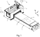
- figure 1 shows an axonometric view of the work center object of the present invention.
- the work center C for machining panels made of wood, ceramic, plastic, glass, fiberglass, and the like, provided with a replaceable work surface, object of the present invention essentially comprises a base 1, through which said work center C rests on the ground, a working plane 2, for supporting the pieces to be machined, a working unit 3, equipped with workpiece machining tools, such as for example a blade disk, a logic control unit U, a memory unit M, and an interface I.
- Said base 1 has an elongated shape, the main dimension of which extends according to a development direction parallel to a first X-axis.
- Said working plane 2 is coupled to said base 1 and has an elongated shape, the main dimension of which extends in a development direction parallel to said first axis X, and lies in a plane XY, where Y is a second axis , orthogonal to said first axis X.
- the working plane 2 comprises openings, not shown in the figure, connected to a vacuum system.
- Said working plane 2 further comprises at least one replaceable working plane 21, which develops in a direction parallel to said first axis X, coupled to said working plane by means of fastening means, such as, for example, screws.
- Said replaceable working plane 21 is porous and composed of one or more coplanar replaceable worktops, or martyr panels.
- Said replaceable working plane 21 is capable of supporting one or more panels to be worked; the porosity of the replaceable working plane 21, in fact, allows the vacuum system to generate a negative pressure on the panel to be worked, so as to make it adhere to the replaceable working plane 21 itself.
- Said working unit 3 is slidably coupled to said base 1 to translate according to said first axis X.
- Said working unit 3 comprises working tools, not shown in the figure, for machining said one or more panels to be worked resting on said working plane 2, as in particular a disc blade.
- Said working unit 3 further comprises a working head, supported by a crosspiece, movable along one axis, two or three translation axes, and rotating with respect to one axis, two axes, or three rotation axes, capable of supporting and actuating related working tools.
- the working unit 3 is also covered by a protective casing.
- Said working unit 3 is capable of leveling operations on said replaceable working plane 21.
- Said memory unit M is capable of memorizing the cutting schemes to be performed on a panel to be worked, a plurality of information, and data provided by said control logic unit U.
- Said control logic unit U is operatively connected to said memory unit M and to said interface I.
- Said control logic unit U is able to perform operations to determine when it is necessary to carry out the leveling of said replaceable working plane 21.
- Said control logic unit U is also capable of counting the number of leveling operations performed and of signaling the need to replace the replaceable working plane 21 when the sum of the leveling operations has reached a predetermined number.
- a first operation that can be performed by said logic control unit U is the measurement of the frequency with which an operator carries out a leveling or replacement operation of said replaceable working plane 21.
- said logic control unit U is capable of counting the number of cutting schemes performed between two flats and of calculating functions of these numbers.
- a function calculated by said control logic unit U is the average of the number of different cutting schemes performed on the worked panel.
- a second operation that can be performed by said control logic unit U is the calculation of the surface of said replaceable working plane 21, which has been worn by through machining, and the determination of the spatial location on said replaceable working plane 21 of the worn portions, and to send these values to said memory unit M.
- said logic control unit U is capable of calculating the surface of said replaceable working plane 21, which has been worn and the location space on said replaceable working plane 21 of the worn portions.
- a further method of calculating the worn surface of the replaceable worktable 21 is as follows.
- a two-dimensional square grid contained in the XY plane is associated with the replaceable working plane 21.
- a binary value 0 or 1 is associated with each cell of the grid, where 0 indicates a worn portion and 1 indicates a non-worn portion.
- the calculation of the repetitions of 0 and 1 indicates the percentage of wear or less of the replaceable working plane 21.
- the surface of the replaceable working plane 21 is shown in three-dimensional form.
- the cutting schemes to be performed are projected onto the three-dimensional surface and the percentage of the surface consumed due to the execution of the cutting scheme is simulated.
- Said control logic unit U is able to generate a first signal S', a second signal S", and a third signal S′′′ following the execution of said operations, and to send them to said interface I.
- Said interface I is capable of receiving said first signal S', second signal S" and third signal S′′′ from said control logic unit U, and correspondingly displaying a smoothing signal T, a substitution signal Q, and a positioning signal V to a user.
- Said control logic unit U is also able to generate a signal R following the execution of said operations and to send it to said working unit 3, which is able to directly carry out the leveling.
- Said work center C can comprise a vision system or an optical device, such as for example a television camera, able to scan said replaceable working plane 21.
- Said television camera can be arranged in different points of said work center C.
- said video camera can be coupled to the working unit 3, so as to move integrally with it, or it can be coupled to said base 1, or alternatively it can consist of an aggregate, which can be coupled to the working unit similar to a tool.
- Said video camera scans the replaceable working plane 21, as soon as the latter is fixed to the working plane 2, to create a three-dimensional reference map, and sends it to the control logic unit U.
- the scan is repeated and the resulting three-dimensional map is sent to the control logic unit U.
- the control logic unit U then compares the two three-dimensional maps to determine the state of wear of the replaceable work table 21.
- the user positions said one or more panels to be worked on said replaceable working plane 21.
- Said control logic unit U actuates said vacuum system, so as to secure said one or more panels to be worked on said replaceable working plane 21.
- Said working unit 3 then performs the required machining operations on said one or more panels to be machined, according to a predetermined cutting scheme.
- said control logic unit U calculates, according to the methods described above, the surface of said replaceable working plane 21, which has been worn by through machining and the spatial location on said replaceable working plane 21 of the worn portions.
- Said control logic unit U stores in said memory unit M the value of worn surface and the spatial location of said surface on said at least one replaceable working plane 21.
- Said control logic unit U also calculates and stores in said memory unit M the number of cutting schemes performed since the last leveling of said replaceable working plane 21 and the number of leveling performed on the same replaceable working plane 21.
- said logic control unit U updates the count of the number of cutting schemes performed since the last leveling.
- control logic unit U compares the spatial location of the previously worn surface with the surface which will be worn by the new cutting scheme, so as to exclude from the total count the portions, which have already been worn by previous cutting schemes.
- said logic control unit U sends said first signal S'to said interface I.
- said logic control unit U can calculate the average of the number of cutting schemes performed between two levellings of said replaceable working plane 21, and updating the average at each new leveling operation.
- said control logic unit U can then send said first signal S' to said interface I, so that face milling is performed automatically, by said working unit 3 of said replaceable working plane 21, upon activation by an operator.
- Said interface I therefore, shows a corresponding leveling signal T.
- Said leveling signal T can be of a light, sound, or visual type, such as for example a light bar whose color filling increases until it reaches the state of wear of said replaceable working plane 21 such as to require a leveling operation.
- Said light bar can also take on colors from green to yellow to red, in correspondence with the state of wear of the replaceable working plane 21.
- the light bar can be green in color, in correspondence with the intact replaceable working plane 21, yellow in color in correspondence with the replaceable working plane 21 worn out for 90%, and red colored when the replaceable surface 21 is completely worn out.
- said interface I it is also possible for said interface I to show text messages to the operator in correspondence with the color of the light bar.
- said control logic unit U sends said second signal S" to said interface I.
- Said interface I therefore, shows a corresponding replacement signal Q of said replaceable working plane 21, so that the manual or automatic replacement of said replaceable working plane 21 is performed.
- the automatic replacement of said replaceable working plane 21 can be performed by an external handling device to said work center, or by a handling device, which can be coupled to said work center, particularly to said working unit 3.
- Said handling device can be an anthropomorphic or Cartesian robot.
- Said replacement signal Q can be of the light, sound, or visual type, such as for example a status bar, the filling of which increases until it reaches the state of wear of said replaceable working plane 21, so as to require a replacement operation, such as previously described.
- said control logic unit U sends said third signal S′′′ to said interface I, so that the manual or automatic replacement of one or more portions of said replaceable working plane 21 is performed.
- Said interface I shows a location signal V to a user to indicate which portions of said worktop replaceable 21 are usable and which ones are no longer usable.
- control logic unit U sends said first S', second S", and third S′′′ signal to said cloud, which in turn sends them to remote devices, such as for example smartphones, tablets, devices wearables, or integrated personal computers of the work center C.
- said logic control unit U sends said signal R to said working unit 3.
- said working unit 3 automatically performs a leveling operation of said at least one replaceable working plane 21.
- control logic unit U can furthermore comprise a predictive algorithm, based for example on a neural network, which is initially manually trained, to recognize the conditions of said replaceable working plane 21, for which the smoothing and replacement operations are necessary, to then automatically send messages and/or signals to said interface I, whenever it is necessary to level or replace said replaceable working plane 21.
- a predictive algorithm based for example on a neural network, which is initially manually trained, to recognize the conditions of said replaceable working plane 21, for which the smoothing and replacement operations are necessary, to then automatically send messages and/or signals to said interface I, whenever it is necessary to level or replace said replaceable working plane 21.
- Said interface I can be a personal computer integrated into the work center C, or one smartphone, a tablet, a wearable device, or a combination of the above different devices, which communicate with said control logic unit U wirelessly.
- Said memory unit M can be a cloud, connected to the control logic unit U via an Internet network.
- a first obvious advantage of the present invention is the possibility of having a work center provided with a replaceable working plane whose levelling and replacement are optimized.
Landscapes
- Engineering & Computer Science (AREA)
- Mechanical Engineering (AREA)
- Life Sciences & Earth Sciences (AREA)
- Wood Science & Technology (AREA)
- Forests & Forestry (AREA)
- Numerical Control (AREA)
- Electrical Discharge Machining, Electrochemical Machining, And Combined Machining (AREA)
Abstract
Description
- The present invention relates to a working center for working panels made of wood, ceramic, plastic, metal, glass, fiberglass, and the like, provided with a replaceable work surface.
- The present invention also relates to an operating method of said improved work center.
- In more detail, the invention relates to a working center of the above type, designed and realized in particular to carry out nesting through machining, in order to obtain a plurality of pieces of different sizes, starting from a single piece, using a tool, such as for example a disc or shaped blade, cylindrical or shaped cutters, and the like.
- In the following, the description will be addressed to a working center for wooden pieces, but it is clear that it should not be considered limited to this specific use.
- As is well known, there are currently work centers provided with a base and a work surface, to which a replaceable work surface layer, or martyr panel, is coupled.
- By replaceable working plane layer, it is meant a continuous surface, made up of one or more panels, used for passing through machining in the vertical direction, i.e. orthogonal to the surface itself, or oblique, to make inclined cuts, provided with means for fixing the piece to be work, generally a vacuum system.
- The replaceable working planes are designed to avoid damaging the underlying working plane, made of metallic material, and therefore to be worn out during the machining performed on the panel to be machined.
- The replaceable working plane is connected to the underlying working plane by screws or other fastening systems. The working plane is also provided with a plurality of openings, connected to a vacuum generation system, which transmits the vacuum to the replaceable working plane that is made of transpiring material and thus allows the workpiece to adhere to work on the replaceable working plane itself.
- For correct machining of the workpiece, it is necessary that it adheres to the replaceable work surface at least for most of its surface.
- In particular, during through machining, the replaceable work plane is worn by the tool along a path outlined by the cutting scheme of the machining itself.
- The execution of each cutting scheme, therefore, wears and affects the replaceable working plane in different portions, decreasing the adhesion surface of the panel to be worked on to the replaceable working plane; to guarantee the adhesion of the panel to be worked on to the replaceable working plane, therefore, it is necessary to carry out periodic leveling of the replaceable working plane, also to eliminate the portions engraved in the previous machining, and thus allow the perfect transmission of the vacuum to the piece to be worked.
- During the leveling, a tool reduces the thickness of the replaceable working plane, so as to once again obtain a uniformly planar surface, without incisions, on which to rest and adhere the panel to be worked.
- Each leveling, therefore, reduces the thickness of the replaceable working plane.
- For example, the thickness of the replaceable working plane is initially 18 mm, and at the limit of wear, it reaches a thickness of 8 mm.
- When the replaceable working plane has been leveled enough times that its thickness is too thin, it must be replaced with a new replaceable working plane.
- To date, the frequency of the leveling and the frequency of replacement of said replaceable working plane are determined by an operator, based solely on his own visual judgment of the state of wear of the replaceable working plane and on his own experience.
- In particular, to date, the execution of cutting schemes continues until the wear of the replaceable working plane is such as to compromise the stability of the panel to be worked.
- An obvious disadvantage of this solution is the possibility that it may be necessary to level or replace the replaceable working plane during the execution of a process, which would cause the interruption of the machining and therefore a considerable increase in times, even exceeding thirty minutes. and therefore of processing costs.
- Another disadvantage is given by the fact that the panel to be machined can move during the working, due to the wear of the replaceable working plane.
- Leveling and replacement of the replaceable working plane at fixed periodic intervals are also envisaged, i.e., which do not take into account the effective state of wear of the replaceable working plane.
- An evident drawback of this solution is the possibility that the replaceable working plane is leveled in advance, resulting in higher operating costs for the work center and longer machining times.
- It is also possible that the replaceable working plane is leveled late, compromising the adhesion of the panel to be worked on to the surface itself and therefore the quality of the work, since the worked pieces are damaged or cut incorrectly.
- In light of the above, it is, therefore, an object of the present invention to provide a work center provided with a replaceable working plane whose leveling and replacement are optimized.
- Another object of the present invention is to provide a method capable of optimizing the replacement of the replaceable working plane.
- It is, therefore, object of the present invention a working center for working panels made of wood, ceramic, plastic, glass, fiberglass and the like, comprising at least one replaceable working plane, a storage unit, in which one or more reference thresholds relating to the state of wear of said replaceable working plane are stored, and cutting schemes to be carried out on said panels, a logic control unit operatively connected to said storage unit, said working center being characterized in that said logic control unit is capable of acquiring data relating to the actual state of wear of said replaceable working plane, calculating the worn surface of said replaceable working plane according to said acquired data, comparing said calculated worn surface with said one or more stored reference thresholds, and emitting signals corresponding to said comparison.
- Further according to the invention, said working center comprises a graphic interface, operatively connected to said logic control unit, and said logic control unit is capable of sending said signals corresponding to said comparison to said graphic interface (I), for displaying to an operator.
- Still according to the invention, said data relating to the actual wear of said replaceable working plane comprise the number of cutting schemes carried out after levelling of said replaceable working plane.
- Preferably according to the invention, said data relating to the actual wear of said replaceable working plane comprise the number of levelling carried out on said replaceable working plane, since said working plane was replaced.
- Always according to the invention, said data relating to the actual wear of said replaceable working plane comprise the measurement of the worn surface of said replaceable working plane.
- Further according to the invention, said working center comprises at least one optic device capable of carrying out an initial scan of said replaceable working plane and generating a corresponding three-dimensional reference map of said replaceable working plane, and carrying out periodic scans of said replaceable working surface and generating corresponding actual three-dimensional maps of said replaceable working plane.
- Still according to the invention, said three-dimensional reference map and said three-dimensional actual maps are stored in said storage unit, and said logic control unit is capable of comparing said three-dimensional actual maps with said three-dimensional reference maps.
- Preferably according to the invention, said working center comprises displaying means, such as a light bar, for displaying the calculated state of wear of said replaceable working plane.
- Always according to the invention, said working center comprises a working unit for carrying out the working on said pieces, and said logic control unit is capable of sending said signals to said working unit for carrying out the levelling and/or the replacement of said replaceable working plane.
- Further according to the invention, said working center comprises a moving device, and said logic control unit is capable of sending said signals to said moving device for carrying out the replacement of said replaceable working plane.
- Still according to the invention, said storage unit is a cloud unit, that can be connected to said logic control unit by means of an Internet network.
- It is further object of the present invention an operating method of a working center (C), comprising the following steps:
- a. acquiring data on the actual state of wear of said replaceable working plane;
- b. calculating the worn surface of said replaceable working plane according to said data acquired in said step a.;
- c. comparing said worn surface calculated in said step b. with one or more stored reference thresholds;
- d. emitting signals corresponding to said comparison carried out in said step b.
- Further according to the invention, said method comprises the following further step:
e. sending said one or more signals emitted in said step d. to said graphic interface for displaying to an operator. - Still according to the invention, said data relating to the actual wear of said replaceable working plane comprise the number of cutting schemes carried out after the leveling of said replaceable working plane.
- Preferably according to the invention, said data relating to the actual wear of said replaceable working surface comprise the number of leveling carried out on said replaceable working surface.
- Finally according to the invention, said data relating to the actual wear of said replaceable working surface comprise the measurement of the worn surface of said replaceable working plane.
- The present invention will be now described, for illustrative but not limitative purposes, according to its preferred embodiments, with particular reference to the figures of the enclosed drawings, wherein:
figure 1 shows an axonometric view of the work center object of the present invention. - With reference to
figure 1 , the work center C for machining panels made of wood, ceramic, plastic, glass, fiberglass, and the like, provided with a replaceable work surface, object of the present invention, essentially comprises abase 1, through which said work center C rests on the ground, a workingplane 2, for supporting the pieces to be machined, a workingunit 3, equipped with workpiece machining tools, such as for example a blade disk, a logic control unit U, a memory unit M, and an interface I. - Said
base 1 has an elongated shape, the main dimension of which extends according to a development direction parallel to a first X-axis. - Said working
plane 2 is coupled to saidbase 1 and has an elongated shape, the main dimension of which extends in a development direction parallel to said first axis X, and lies in a plane XY, where Y is a second axis , orthogonal to said first axis X. - The
working plane 2 comprises openings, not shown in the figure, connected to a vacuum system. - Said working
plane 2 further comprises at least onereplaceable working plane 21, which develops in a direction parallel to said first axis X, coupled to said working plane by means of fastening means, such as, for example, screws. - Said
replaceable working plane 21 is porous and composed of one or more coplanar replaceable worktops, or martyr panels. - Said
replaceable working plane 21 is capable of supporting one or more panels to be worked; the porosity of thereplaceable working plane 21, in fact, allows the vacuum system to generate a negative pressure on the panel to be worked, so as to make it adhere to thereplaceable working plane 21 itself. - Said working
unit 3 is slidably coupled to saidbase 1 to translate according to said first axis X. - Said working
unit 3 comprises working tools, not shown in the figure, for machining said one or more panels to be worked resting on said workingplane 2, as in particular a disc blade. - Said working
unit 3 further comprises a working head, supported by a crosspiece, movable along one axis, two or three translation axes, and rotating with respect to one axis, two axes, or three rotation axes, capable of supporting and actuating related working tools. The workingunit 3 is also covered by a protective casing. - Said working
unit 3 is capable of leveling operations on said replaceable workingplane 21. - Said memory unit M is capable of memorizing the cutting schemes to be performed on a panel to be worked, a plurality of information, and data provided by said control logic unit U.
- Said control logic unit U is operatively connected to said memory unit M and to said interface I.
- Said control logic unit U is able to perform operations to determine when it is necessary to carry out the leveling of said replaceable working
plane 21. - Said control logic unit U is also capable of counting the number of leveling operations performed and of signaling the need to replace the replaceable working
plane 21 when the sum of the leveling operations has reached a predetermined number. - A first operation that can be performed by said logic control unit U is the measurement of the frequency with which an operator carries out a leveling or replacement operation of said replaceable working
plane 21. - In particular, said logic control unit U is capable of counting the number of cutting schemes performed between two flats and of calculating functions of these numbers.
- For example, a function calculated by said control logic unit U is the average of the number of different cutting schemes performed on the worked panel.
- A second operation that can be performed by said control logic unit U is the calculation of the surface of said replaceable working
plane 21, which has been worn by through machining, and the determination of the spatial location on said replaceable workingplane 21 of the worn portions, and to send these values to said memory unit M. - In particular, once the tool used and the cutting scheme is known, said logic control unit U is capable of calculating the surface of said replaceable working
plane 21, which has been worn and the location space on said replaceable workingplane 21 of the worn portions. - A further method of calculating the worn surface of the
replaceable worktable 21 is as follows. - A two-dimensional square grid contained in the XY plane is associated with the replaceable working
plane 21. Abinary value 0 or 1 is associated with each cell of the grid, where 0 indicates a worn portion and 1 indicates a non-worn portion. - The calculation of the repetitions of 0 and 1 indicates the percentage of wear or less of the replaceable working
plane 21. - Yet another way of calculating the worn surface of the replaceable working
plane 21 is as follows. - The surface of the replaceable working
plane 21 is shown in three-dimensional form. - The cutting schemes to be performed are projected onto the three-dimensional surface and the percentage of the surface consumed due to the execution of the cutting scheme is simulated.
- Said control logic unit U is able to generate a first signal S', a second signal S", and a third signal S‴ following the execution of said operations, and to send them to said interface I.
- Said interface I is capable of receiving said first signal S', second signal S" and third signal S‴ from said control logic unit U, and correspondingly displaying a smoothing signal T, a substitution signal Q, and a positioning signal V to a user.
- Said control logic unit U is also able to generate a signal R following the execution of said operations and to send it to said working
unit 3, which is able to directly carry out the leveling. - Said work center C can comprise a vision system or an optical device, such as for example a television camera, able to scan said replaceable working
plane 21. - Said television camera can be arranged in different points of said work center C.
- In particular, said video camera can be coupled to the working
unit 3, so as to move integrally with it, or it can be coupled to saidbase 1, or alternatively it can consist of an aggregate, which can be coupled to the working unit similar to a tool. - Said video camera scans the replaceable working
plane 21, as soon as the latter is fixed to the workingplane 2, to create a three-dimensional reference map, and sends it to the control logic unit U. - Following a predetermined number of cutting schemes, the scan is repeated and the resulting three-dimensional map is sent to the control logic unit U.
- The control logic unit U then compares the two three-dimensional maps to determine the state of wear of the replaceable work table 21.
- The operation of the work center C provided with a replaceable working plane described above, proceeds as follows.
- When it is intended to work one or more panels in wood, ceramic, plastic, metal, glass, fiberglass, and the like, a user positions them on said working
plane 2. - In particular, the user positions said one or more panels to be worked on said replaceable working
plane 21. - Said control logic unit U actuates said vacuum system, so as to secure said one or more panels to be worked on said replaceable working
plane 21. - Said working
unit 3 then performs the required machining operations on said one or more panels to be machined, according to a predetermined cutting scheme. - Once the cutting scheme and the tools used are known, said control logic unit U calculates, according to the methods described above, the surface of said replaceable working
plane 21, which has been worn by through machining and the spatial location on said replaceable workingplane 21 of the worn portions. - Said control logic unit U stores in said memory unit M the value of worn surface and the spatial location of said surface on said at least one replaceable working
plane 21. - Said control logic unit U also calculates and stores in said memory unit M the number of cutting schemes performed since the last leveling of said replaceable working
plane 21 and the number of leveling performed on the same replaceable workingplane 21. - When one intends to carry out a new cutting scheme, said logic control unit U updates the count of the number of cutting schemes performed since the last leveling.
- Furthermore, said control logic unit U compares the spatial location of the previously worn surface with the surface which will be worn by the new cutting scheme, so as to exclude from the total count the portions, which have already been worn by previous cutting schemes.
- When the worn surface value of said replaceable working
plane 21 exceeds a predetermined threshold, said logic control unit U sends said first signal S'to said interface I. - Alternatively, said logic control unit U can calculate the average of the number of cutting schemes performed between two levellings of said replaceable working
plane 21, and updating the average at each new leveling operation. - When the number of cutting schemes reaches a value equal to the average calculated from the number of previously performed cutting schemes, said control logic unit U can then send said first signal S' to said interface I, so that face milling is performed automatically, by said working
unit 3 of said replaceable workingplane 21, upon activation by an operator. - Said interface I, therefore, shows a corresponding leveling signal T.
- Said leveling signal T can be of a light, sound, or visual type, such as for example a light bar whose color filling increases until it reaches the state of wear of said replaceable working
plane 21 such as to require a leveling operation. - Said light bar can also take on colors from green to yellow to red, in correspondence with the state of wear of the replaceable working
plane 21. - For example, the light bar can be green in color, in correspondence with the intact replaceable working
plane 21, yellow in color in correspondence with the replaceable workingplane 21 worn out for 90%, and red colored when thereplaceable surface 21 is completely worn out. - It is also possible for said interface I to show text messages to the operator in correspondence with the color of the light bar.
- When said replaceable working
plane 21 has been leveled for a predetermined number of times, such as to make it no longer suitable for machining, said control logic unit U sends said second signal S" to said interface I. - Said interface I, therefore, shows a corresponding replacement signal Q of said replaceable working
plane 21, so that the manual or automatic replacement of said replaceable workingplane 21 is performed. - The automatic replacement of said replaceable working
plane 21 can be performed by an external handling device to said work center, or by a handling device, which can be coupled to said work center, particularly to said workingunit 3. - Said handling device can be an anthropomorphic or Cartesian robot.
- Said replacement signal Q can be of the light, sound, or visual type, such as for example a status bar, the filling of which increases until it reaches the state of wear of said replaceable working
plane 21, so as to require a replacement operation, such as previously described. - When a specific portion of said replaceable working
plane 21 is excessively worn, it is also possible that said control logic unit U sends said third signal S‴ to said interface I, so that the manual or automatic replacement of one or more portions of said replaceable workingplane 21 is performed. - Said interface I then shows a location signal V to a user to indicate which portions of said worktop replaceable 21 are usable and which ones are no longer usable.
- It is also possible that the control logic unit U sends said first S', second S", and third S‴ signal to said cloud, which in turn sends them to remote devices, such as for example smartphones, tablets, devices wearables, or integrated personal computers of the work center C.
- Alternatively, when the worn surface value of said replaceable working
plane 21 exceeds a predetermined threshold, said logic control unit U sends said signal R to said workingunit 3. - Before switching, therefore, when the next panel is machined, said working
unit 3 automatically performs a leveling operation of said at least one replaceable workingplane 21. - It is also possible to set in said control logic unit U a predetermined thickness intervals of said replaceable working
plane 21, in correspondence with which the leveling or replacements are to be carried out, mainly when said work center C is placed in line with other machines. - Finally, said control logic unit U can furthermore comprise a predictive algorithm, based for example on a neural network, which is initially manually trained, to recognize the conditions of said replaceable working
plane 21, for which the smoothing and replacement operations are necessary, to then automatically send messages and/or signals to said interface I, whenever it is necessary to level or replace said replaceable workingplane 21. - Said interface I can be a personal computer integrated into the work center C, or one smartphone, a tablet, a wearable device, or a combination of the above different devices, which communicate with said control logic unit U wirelessly.
- Said memory unit M, can be a cloud, connected to the control logic unit U via an Internet network.
- A first obvious advantage of the present invention is the possibility of having a work center provided with a replaceable working plane whose levelling and replacement are optimized.
- The present invention has been described for illustrative but not limitative purposes, according to its preferred embodiments, but it is to be understood that modifications and/or changes can be introduced by those skilled in the art without departing from the relevant scope as defined in the enclosed claims.
Claims (16)
- Working center (C) for working panels made of wood, ceramic, plastic, glass, fiberglass and the like, comprisingat least one replaceable working plane (21),a storage unit (M), in which one or more reference thresholds relating to the state of wear of said replaceable working plane are stored (21), and cutting schemes to be carried out on said panels,a logic control unit (U) operatively connected to said storage unit (M), said working center (C) being characterized in that said logic control unit (U) is capable ofacquiring data relating to the actual state of wear of said replaceable working plane (21),calculating the worn surface of said replaceable working plane (21) according to said acquired data,comparing said calculated worn surface with said one or more stored reference thresholds, andemitting signals corresponding to said comparison.
- Working center (C) according to the preceding claim, characterizedin that it comprises a graphic interface (I), operatively connected to said logic control unit (U), andin that said logic control unit (U) is capable of sending said signals corresponding to said comparison to said graphic interface (I), for displaying to an operator.
- Working center (C) according to any one of the preceding claims, characterized in that said data relating to the actual wear of said replaceable working plane (21) comprise the number of cutting schemes carried out after levelling of said replaceable working plane (21).
- Working center (C) according to any one of the preceding claims, characterized in that said data relating to the actual wear of said replaceable working plane (21) comprise the number of levelling carried out on said replaceable working plane (21), since said working plane was replaced (21).
- Working center (C) according to any one of the preceding claims, characterized in that said data relating to the actual wear of said replaceable working plane (21) comprise the measurement of the worn surface of said replaceable working plane (21).
- Working center (C) according to any one of the preceding claims, characterized in that it comprises at least one optic device capable ofcarrying out an initial scan of said replaceable working plane (21) and generating a corresponding three-dimensional reference map of said replaceable working plane (21), andcarrying out periodic scans of said replaceable working surface (21) and generating corresponding actual three-dimensional maps of said replaceable working plane (21).
- Working center (C) according to the preceding claim, characterizedin that said three-dimensional reference map and said three-dimensional actual maps are stored in said storage unit (M), andin that said logic control unit (U) is capable of comparing said three-dimensional actual maps with said three-dimensional reference maps.
- Working center (C) according to any one of the preceding claims, characterized in that it comprises displaying means, such as a light bar, for displaying the calculated state of wear of said replaceable working plane (21).
- Working center (C) according to any one of the preceding claims, characterizedin that it comprises a working unit (3) for carrying out the working on said pieces, andin that said logic control unit (U) is capable of sending said signals to said working unit (3) for carrying out the leveling and/or the replacement of said replaceable working plane (21).
- Working center (C) according to any one of the preceding claims, characterizedin that it comprises a moving device, andin that said logic control unit (U) is capable of sending said signals to said moving device for carrying out the replacement of said replaceable working plane (21).
- Working center (C) according to any one of the preceding claims, characterized in that said storage unit (M) is a cloud unit, that can be connected to said logic control unit (U) by means of an Internet network.
- Operating method of a working center (C), as described in any one of the preceding claims, characterized in that it comprises the following steps:a. acquiring data on the actual state of wear of said replaceable working plane (21);b. calculating the worn surface of said replaceable working plane (21) according to said data acquired in said step a.;c. comparing said worn surface calculated in said step b. with one or more stored reference thresholds;d. emitting signals corresponding to said comparison carried out in said step b.
- Operating method according to the preceding claim, when said working center (C) comprises a graphic interface (I), operatively connected to said logic control unit (U), characterized in that it comprises the following further step:
e. sending said one or more signals emitted in said step d. to said graphic interface (I) for displaying to an operator. - Method according to any one of claims 12 or 13, characterized in that said data relating to the actual wear of said replaceable working plane (21) comprise the number of cutting schemes carried out after the leveling of said replaceable working plane (21).
- Method according to any one of claims 12 - 14, characterized in that said data relating to the actual wear of said replaceable working surface (21) comprise the number of leveling carried out on said replaceable working surface (21).
- Method according to any one of claims 12 - 15, characterized in that said data relating to the actual wear of said replaceable working surface (21) comprise the measurement of the worn surface of said replaceable working plane (21).
Applications Claiming Priority (1)
| Application Number | Priority Date | Filing Date | Title |
|---|---|---|---|
| IT102021000027398A IT202100027398A1 (en) | 2021-10-26 | 2021-10-26 | IMPROVED WORKING CENTER AND RELATED OPERATION METHOD. |
Publications (2)
| Publication Number | Publication Date |
|---|---|
| EP4173786A1 true EP4173786A1 (en) | 2023-05-03 |
| EP4173786B1 EP4173786B1 (en) | 2026-01-28 |
Family
ID=79270036
Family Applications (1)
| Application Number | Title | Priority Date | Filing Date |
|---|---|---|---|
| EP22203168.4A Active EP4173786B1 (en) | 2021-10-26 | 2022-10-24 | Improved working center and operating method thereof |
Country Status (2)
| Country | Link |
|---|---|
| EP (1) | EP4173786B1 (en) |
| IT (1) | IT202100027398A1 (en) |
Citations (1)
| Publication number | Priority date | Publication date | Assignee | Title |
|---|---|---|---|---|
| WO2015185351A1 (en) * | 2014-06-04 | 2015-12-10 | Holzma Plattenaufteiltechnik Gmbh | Method for operating a panel-processing installation, and panel-processing installation |
-
2021
- 2021-10-26 IT IT102021000027398A patent/IT202100027398A1/en unknown
-
2022
- 2022-10-24 EP EP22203168.4A patent/EP4173786B1/en active Active
Patent Citations (1)
| Publication number | Priority date | Publication date | Assignee | Title |
|---|---|---|---|---|
| WO2015185351A1 (en) * | 2014-06-04 | 2015-12-10 | Holzma Plattenaufteiltechnik Gmbh | Method for operating a panel-processing installation, and panel-processing installation |
Also Published As
| Publication number | Publication date |
|---|---|
| IT202100027398A1 (en) | 2023-04-26 |
| EP4173786B1 (en) | 2026-01-28 |
Similar Documents
| Publication | Publication Date | Title |
|---|---|---|
| CN114830053B (en) | Method and device for determining cutting parameters of a laser cutting machine | |
| GB2192075A (en) | Generating toolpath in cadcam system | |
| US10386814B2 (en) | Machining status display apparatus, and NC program generating apparatus and NC program editing apparatus provided with the same | |
| CN109048494B (en) | energy consumption type based tool life comprehensive management method and system | |
| US10031512B2 (en) | Apparatus for generating and editing NC program | |
| EP4173786B1 (en) | Improved working center and operating method thereof | |
| US20180290257A1 (en) | System and method for compensating deviations in an optical lens manufacturing process | |
| CN110153800B (en) | Tool life management method | |
| US5757647A (en) | Computer assisted, manual workstation | |
| WO2018224932A1 (en) | Method of manufacturing a shoe last and system thereof | |
| CN119989635A (en) | Chip breaker processing method and system | |
| KR20200072827A (en) | System for managing a cutting tool and method for managing a cutting tool thereof | |
| EP3690572B1 (en) | Operating condition management system, operating condition management method, and operating condition management computer program | |
| JPH06155245A (en) | Tool life management method | |
| KR102530261B1 (en) | Apparatus and method for checking tool life based on tool using time | |
| CN212352466U (en) | Intelligent vision profiling stone cutting robot | |
| KR102188017B1 (en) | Measurement and Management System for Mold Manufacture Machine | |
| CN116957857B (en) | Building restoration method and device and electronic equipment | |
| JP2021015333A (en) | Machine tool system and method of estimating machine tool specifications | |
| KR100303237B1 (en) | Pattern processing method and apparatus using laser | |
| US11992891B2 (en) | Machining method of wire discharge machine, machining program generating device, wire discharge machining system and machined object manufacturing method | |
| JP2022066722A (en) | Machine tool system, and selection method of machine tool candidate | |
| CN114492702A (en) | A method, storage medium and server for generating edge banding information of a panel | |
| US20220147014A1 (en) | Operating device and method | |
| KR102633846B1 (en) | Automatic Lathe Control System and the method for Productivity Improvement of Multi-Variety Small Volume Products |
Legal Events
| Date | Code | Title | Description |
|---|---|---|---|
| PUAI | Public reference made under article 153(3) epc to a published international application that has entered the european phase |
Free format text: ORIGINAL CODE: 0009012 |
|
| STAA | Information on the status of an ep patent application or granted ep patent |
Free format text: STATUS: THE APPLICATION HAS BEEN PUBLISHED |
|
| AK | Designated contracting states |
Kind code of ref document: A1 Designated state(s): AL AT BE BG CH CY CZ DE DK EE ES FI FR GB GR HR HU IE IS IT LI LT LU LV MC ME MK MT NL NO PL PT RO RS SE SI SK SM TR |
|
| P01 | Opt-out of the competence of the unified patent court (upc) registered |
Effective date: 20230518 |
|
| STAA | Information on the status of an ep patent application or granted ep patent |
Free format text: STATUS: REQUEST FOR EXAMINATION WAS MADE |
|
| 17P | Request for examination filed |
Effective date: 20231027 |
|
| RBV | Designated contracting states (corrected) |
Designated state(s): AL AT BE BG CH CY CZ DE DK EE ES FI FR GB GR HR HU IE IS IT LI LT LU LV MC ME MK MT NL NO PL PT RO RS SE SI SK SM TR |
|
| GRAP | Despatch of communication of intention to grant a patent |
Free format text: ORIGINAL CODE: EPIDOSNIGR1 |
|
| STAA | Information on the status of an ep patent application or granted ep patent |
Free format text: STATUS: GRANT OF PATENT IS INTENDED |
|
| INTG | Intention to grant announced |
Effective date: 20250910 |
|
| GRAS | Grant fee paid |
Free format text: ORIGINAL CODE: EPIDOSNIGR3 |
|
| GRAA | (expected) grant |
Free format text: ORIGINAL CODE: 0009210 |
|
| STAA | Information on the status of an ep patent application or granted ep patent |
Free format text: STATUS: THE PATENT HAS BEEN GRANTED |
|
| AK | Designated contracting states |
Kind code of ref document: B1 Designated state(s): AL AT BE BG CH CY CZ DE DK EE ES FI FR GB GR HR HU IE IS IT LI LT LU LV MC ME MK MT NL NO PL PT RO RS SE SI SK SM TR |
|
| REG | Reference to a national code |
Ref country code: CH Ref legal event code: F10 Free format text: ST27 STATUS EVENT CODE: U-0-0-F10-F00 (AS PROVIDED BY THE NATIONAL OFFICE) Effective date: 20260128 Ref country code: GB Ref legal event code: FG4D |
|
| REG | Reference to a national code |
Ref country code: DE Ref legal event code: R096 Ref document number: 602022029190 Country of ref document: DE |
|
| REG | Reference to a national code |
Ref country code: IE Ref legal event code: FG4D |