EP4173782B1 - Rotary electric shaver - Google Patents
Rotary electric shaver Download PDFInfo
- Publication number
- EP4173782B1 EP4173782B1 EP22193984.6A EP22193984A EP4173782B1 EP 4173782 B1 EP4173782 B1 EP 4173782B1 EP 22193984 A EP22193984 A EP 22193984A EP 4173782 B1 EP4173782 B1 EP 4173782B1
- Authority
- EP
- European Patent Office
- Prior art keywords
- blade
- balls
- rotary electric
- electric shaver
- support
- Prior art date
- Legal status (The legal status is an assumption and is not a legal conclusion. Google has not performed a legal analysis and makes no representation as to the accuracy of the status listed.)
- Active
Links
Images



Classifications
-
- B—PERFORMING OPERATIONS; TRANSPORTING
- B26—HAND CUTTING TOOLS; CUTTING; SEVERING
- B26B—HAND-HELD CUTTING TOOLS NOT OTHERWISE PROVIDED FOR
- B26B19/00—Clippers or shavers operating with a plurality of cutting edges, e.g. hair clippers, dry shavers
- B26B19/28—Drive layout for hair clippers or dry shavers, e.g. providing for electromotive drive
-
- B—PERFORMING OPERATIONS; TRANSPORTING
- B26—HAND CUTTING TOOLS; CUTTING; SEVERING
- B26B—HAND-HELD CUTTING TOOLS NOT OTHERWISE PROVIDED FOR
- B26B19/00—Clippers or shavers operating with a plurality of cutting edges, e.g. hair clippers, dry shavers
- B26B19/14—Clippers or shavers operating with a plurality of cutting edges, e.g. hair clippers, dry shavers of the rotary-cutter type; Cutting heads therefor; Cutters therefor
- B26B19/143—Details of outer cutters
-
- B—PERFORMING OPERATIONS; TRANSPORTING
- B26—HAND CUTTING TOOLS; CUTTING; SEVERING
- B26B—HAND-HELD CUTTING TOOLS NOT OTHERWISE PROVIDED FOR
- B26B19/00—Clippers or shavers operating with a plurality of cutting edges, e.g. hair clippers, dry shavers
- B26B19/14—Clippers or shavers operating with a plurality of cutting edges, e.g. hair clippers, dry shavers of the rotary-cutter type; Cutting heads therefor; Cutters therefor
- B26B19/141—Details of inner cutters having their axes of rotation perpendicular to the cutting surface
-
- B—PERFORMING OPERATIONS; TRANSPORTING
- B26—HAND CUTTING TOOLS; CUTTING; SEVERING
- B26B—HAND-HELD CUTTING TOOLS NOT OTHERWISE PROVIDED FOR
- B26B19/00—Clippers or shavers operating with a plurality of cutting edges, e.g. hair clippers, dry shavers
- B26B19/14—Clippers or shavers operating with a plurality of cutting edges, e.g. hair clippers, dry shavers of the rotary-cutter type; Cutting heads therefor; Cutters therefor
-
- B—PERFORMING OPERATIONS; TRANSPORTING
- B26—HAND CUTTING TOOLS; CUTTING; SEVERING
- B26B—HAND-HELD CUTTING TOOLS NOT OTHERWISE PROVIDED FOR
- B26B19/00—Clippers or shavers operating with a plurality of cutting edges, e.g. hair clippers, dry shavers
- B26B19/14—Clippers or shavers operating with a plurality of cutting edges, e.g. hair clippers, dry shavers of the rotary-cutter type; Cutting heads therefor; Cutters therefor
- B26B19/145—Cutters being movable in the cutting head
-
- B—PERFORMING OPERATIONS; TRANSPORTING
- B26—HAND CUTTING TOOLS; CUTTING; SEVERING
- B26B—HAND-HELD CUTTING TOOLS NOT OTHERWISE PROVIDED FOR
- B26B19/00—Clippers or shavers operating with a plurality of cutting edges, e.g. hair clippers, dry shavers
- B26B19/14—Clippers or shavers operating with a plurality of cutting edges, e.g. hair clippers, dry shavers of the rotary-cutter type; Cutting heads therefor; Cutters therefor
- B26B19/146—Complete cutting head being movable
-
- B—PERFORMING OPERATIONS; TRANSPORTING
- B26—HAND CUTTING TOOLS; CUTTING; SEVERING
- B26B—HAND-HELD CUTTING TOOLS NOT OTHERWISE PROVIDED FOR
- B26B19/00—Clippers or shavers operating with a plurality of cutting edges, e.g. hair clippers, dry shavers
- B26B19/38—Details of, or accessories for, hair clippers, or dry shavers, e.g. housings, casings, grips, guards
- B26B19/3806—Accessories
-
- B—PERFORMING OPERATIONS; TRANSPORTING
- B26—HAND CUTTING TOOLS; CUTTING; SEVERING
- B26B—HAND-HELD CUTTING TOOLS NOT OTHERWISE PROVIDED FOR
- B26B19/00—Clippers or shavers operating with a plurality of cutting edges, e.g. hair clippers, dry shavers
- B26B19/38—Details of, or accessories for, hair clippers, or dry shavers, e.g. housings, casings, grips, guards
- B26B19/3853—Housing or handle
- B26B19/386—Means for attaching the head thereto
Definitions
- the present invention relates to a rotary electric shaver.
- a rotary electric shaver configured to include one blade unit having an outer blade whose outer side has a circular shaving surface and an inner blade which rotates while coming into sliding contact with an inner surface of the outer blade
- a configuration has been proposed in which a total of nine balls are fitted into one location on a central axis of the outer blade and eight locations in a circumferential direction on an outer peripheral part of the outer blade so that a part of each of the balls protrudes (PTL 1: JP-UM-A-61-140767 ).
- a rotary electric shaver having the following configuration is known.
- a plurality of blade units having an outer blade whose outer side has an annular shaving surface and an inner blade which rotates while coming into sliding contact with an inner surface of the outer blade are disposed (PTL 2: JP-A-2015-070927 ).
- PTL 3 discloses a dry-shaving apparatus comprising cutting elements which comprise a central bearing member.
- PTL 4 discloses a shaving apparatus having a skin contact surface accommodating at least one cutting unit.
- a rotary electric shaver has the following advantage.
- a ball When a ball is disposed on a contact surface with skin in a head part, the ball comes into contact with the skin so that a user feels a smooth sense of touch on the skin during shaving.
- a position where a ball receiving member is welded to a minute part of the outer blade is fixed. Consequently, the ball attached to the ball receiving member is likely to be in a biased state. Since the ball is biased, frictional resistance increases, and the ball is brought into a state where the ball is less likely to rotate.
- the ball is fitted into the ball receiving member from an outside of the outer blade, thereby causing a possibility that the outer blade may deform depending on adjustment of a fitting force.
- the inner blade adopts a special shape.
- the configuration disclosed in PTL 1 has many manufacturing problems.
- the configuration disclosed in PTL 2 in which the plurality of blade units are disposed compared to the configuration having one blade unit, it becomes more difficult to dispose the ball on the contact surface with the skin in the head part.
- the present invention is made in view of the above-described circumstances, and an object of the present invention is to provide a rotary electric shaver having the following structure.
- a user feels a smooth sense of touch on skin by disposing two to six balls in an outer blade part, and an inner blade member can safely rotate so that the balls are likely to rotate.
- each of the two to six balls supported by the disk-shaped cover disposed at an inner position of an annular part and the support protrudes from the cover, and each of the two to six balls comes into contact with skin so that a user feels a smooth sense of the touch on the skin during shaving. That is, each of the two to six balls is supported while it is surrounded by the cover and the support.
- a structure can be provided so that the two to six balls is likely to rotate by reducing frictional resistance.
- the number of the balls disposed in each of the outer blade parts is two to six. All of the two to six balls are disposed at positions deviated from the axis of the second driven shaft. In this manner, a size of the outer blade can be easily reduced to such an extent that the outer blade does not interfere with the second driven shaft. Since the two to six balls which are small to such an extent that the balls do not interfere with shaving are disposed, a user feels a smoother sense of the touch on the skin.
- the support has a plurality of ball receiving holes corresponding to the two to six balls on a one-to-one basis and a plurality of claw parts formed at an equal interval in the circumferential direction to protrude from an inner peripheral side of each ball receiving hole, and each of the claw parts is in contact with one of the two to six balls.
- a contact area between each ball and the support can be reduced as much as possible by the claw parts. Accordingly, a structure can be provided so that each ball is more likely to rotate.
- discharge parts are respectively formed on both sides of each of the claw parts. In this manner, even when a shaving waste enters the inside through a gap formed around the ball when the ball is operated in an upward-downward direction, the entering shaving waste passes through the discharge part, passes through the inner blade part, and is collected in a lower shaving waste discharge area. Accordingly, it is possible to prevent accumulation of the shaving waste which hinders an operation of the ball.
- each ball may be made of metal.
- both the cover and the support may be made of a resin.
- the cover may be formed so that a plurality of pins protrude. It is preferable that the support has a plurality of through holes into which the pins are inserted, respectively, and the cover is fitted and assembled to the support. In this manner, the cover and the support can be positioned and fitted to each other. Accordingly, each ball can be easily positioned.
- a first projection part may be formed in a center of the base part, and a first hollow part may be formed inside the first projection part.
- a second projection part may be formed in a center of the support, and the second hollow part may be formed inside the second projection part. It is preferable that the second driven shaft is fitted to the first hollow part, and the first projection part is fitted to the second hollow part. In this manner, the support rotates in conjunction with the second driven shaft while supporting the two to six balls from below. In this manner, each of the two to six balls rolls. Accordingly, the two to six balls can be positively rotated.
- the number of the disposed blade units is two to six.
- Three blade units may be disposed in the head. It is preferable that in the setting part, groove parts having a depth which allows swing movement of the blade unit are formed at an intermediate position between adjacent blade units. In this manner, the three blade units oscillate in accordance with undulations of the skin and come into close contact with the skin. Accordingly, shaving performance can be improved, and an advantageous effect can be expected in that blood circulation is improved by massaging the skin with the two to six balls. It is preferable that the blade setting base is connected to the grip part via a connection part, and the head is capable of tilting with respect to the main body. In this manner, excellent shaving performance is achieved even in a largely undulating area from a chin to a face.
- a rotary electric shaver having the following structure.
- a user feels a smooth sense of touch on skin by disposing two to six balls in an outer blade part, and an inner blade member can safely rotate so that the two to six balls are likely to rotate.
- a rotary electric shaver 1 of the present embodiment has a head 4 having a plurality of blade units 5.
- the rotary electric shaver 1 includes a grip part 15 gripped by a user, and the head 4 detachably connected to a connection part 13 disposed in the grip part 15.
- a front surface side of a main body 2 is an operation panel, and a power switch 53 is disposed.
- a blade setting base 3 is connected to the grip part 15 via the connection part 13, and the head 4 is configured to be capable of tilting with respect to the main body 2.
- the main body 2 has the grip part 15 and the blade setting base 3, and a trimmer 54 is disposed on a back surface side of the main body 2.
- a motor 51, a battery 52 which can supply a direct current to the motor 51, and a controller 55 activated by the power switch 53 are built in the grip part 15 in the main body 2.
- a power supply terminal 58 is disposed in a lower part on the back surface side of the main body 2, and power can be supplied to the battery 52 from an external power source via the power supply terminal 58.
- the motor 51 is connected to a first driven shaft 11 by a first drive part 56 having a plurality of gears.
- a technique in the related art can be applied to the first drive part 56.
- a plurality of second driven shafts 12 are disposed in the blade setting base 3.
- three second driven shafts 12 are disposed at a predetermined interval.
- the first driven shaft 11 is connected to the second driven shaft 12 by a second drive part 57 having a plurality of gears.
- a technique in the related art can be applied to the second drive part 57.
- the head 4 has a setting part 6 having a plurality of blade units 5, and a blade frame 7 that holds the setting part 6.
- three blade units 5 are disposed at a predetermined interval in the head 4.
- each groove part 6a having a depth which allows swing movement of the blade unit 5 is formed at an intermediate position between the blade unit 5 and the blade unit 5.
- three groove parts 6a are formed, and one end of each of the groove parts 6a is connected in a center of the setting part 6.
- the setting part 6 is configured as follows. The setting part 6 is pressed up due to a restoring force of a plate-shaped spring 41 disposed in the blade frame 7.
- Fig. 4 is an enlarged view of a part of the head 4 in Fig. 3 which is surrounded by a broken line E.
- Fig. 5 is a schematic structural development view of the head 4.
- Fig. 6A is a perspective view of a cover 32 in the head 4.
- Fig. 6B is a perspective view of a support 34 in the head 4.
- Fig. 6C is a perspective view of an outer blade member 31 in the head 4.
- Fig. 6D is a perspective view of an inner blade part 9 in the head 4.
- An outer blade part 8 is configured to have the annular outer blade member 31, the disk-shaped cover 32, a plurality of balls 33, and the support 34.
- Each of the blade units 5 has the outer blade part 8 and the inner blade part 9.
- the outer blade part 8 has an outer shaving surface 31a and an inner sliding contact surface 31b with which a blade edge 9a comes into sliding contact, and has the annular and metal-made outer blade member 31 in which a plurality of slits 31c having a size which enables hairs to enter are formed in the circumferential direction.
- examples of the hairs include beards, mustache, whisker, and the like.
- the inner blade part 9 has a metal-made inner blade member 21 in which a plurality of the blade edges 9a are formed in the circumferential direction, and a resin-made base part 22 joined to the inner blade member 21.
- a first projection part 22d is formed in a center of the base part 22, and a first hollow part 22e is formed inside the first projection part 22d.
- a tip part of the second driven shaft 12 is fitted to the first hollow part 22e, the second driven shaft 12 is connected to the base part 22, and the inner blade member 21 is configured to rotate around an axis P1 of the second driven shaft 12.
- a technique in the related art can be applied to the outer blade part 8 and the inner blade part 9.
- the disk-shaped and resin-made cover 32 is disposed inside the annular outer blade member 31.
- the cover 32 has a plurality of circular windows 32a each having a smaller diameter than the corresponding ball in the plurality of balls 33, and has a plurality of pins 32b which are formed to protrude.
- a plurality of the balls 33 are disposed in each of the outer blade members 31.
- three balls 33 are disposed at positions deviated from the axis P1 of the second driven shaft 12.
- the plurality of balls 33 are made of metal, and is made of stainless steel, aluminum, steel, titanium, a copper alloy, a nickel alloy, or other known metal or alloys.
- a surface of the balls 33 can be colored by means of plating or by using an anodic oxide film, for example.
- the plurality of balls 33 can be made of a resin or ceramics.
- a second projection part 34d is formed in the center of the disk-shaped and resin-made support 34, and a plurality of through holes 34a into which the pins 32b are inserted are formed around the second projection part 34d.
- the through hole 34a is set to have a hole diameter which enables the pin 32b to be fitted in a state where the pin 32b is inserted into the through hole 34a.
- the support 34 has a plurality of ball receiving holes 34b corresponding to the plurality of balls 33 on a one-to-one basis.
- the support 34 has a plurality of claw parts 34c protruding from an inner peripheral side of each ball receiving hole 34b at an equal interval in the circumferential direction.
- Each of the claw parts 34c is in contact with one of the plurality of balls 33 to support the ball 33 from below.
- the number of the disposed claw parts 34c is three to five.
- the cover 32 is fitted and assembled to the support 34 in a state where each of the balls 33 is supported from below.
- a part of each ball 33 surrounded by the cover 32 and the support 34 is configured to protrude from the window 32a.
- Each ball receiving hole 34b has discharge parts 34f respectively formed on both sides of each of the claw parts 34c. In this manner, even when a shaving waste enters the inside through a gap formed around the ball 33 when the ball 33 is operated in an upward-downward direction, the entering shaving waste passes through the discharge part 34f, passes through the inner blade part 9, and is collected in a lower shaving waste discharge area. Accordingly, it is possible to prevent accumulation of the shaving waste which hinders an operation of the ball 33.
- each of the discharge parts 34f has a shape in which a position between the claw parts 34c and the claw parts 34c which are disposed adjacent to each other in the circumferential direction is enlarged. Accordingly, the claw part 34c can have a shape which is likely to follow an operation in the upward-downward direction of the ball 33.
- the second projection part 34d is formed in the center of the disk-shaped and resin-made support 34, and a second hollow part 34e is formed inside the second projection part 34d.
- the first projection part 22d is fitted to the second hollow part 34e, and the cover 32 and the support 34 are configured to rotate around the axis P1 of the second driven shaft 12 in conjunction with rotation of the inner blade member 21.
- the rotary electric shaver 1 achieves excellent shaving performance even in a largely undulating area from a chin to a face.
Landscapes
- Life Sciences & Earth Sciences (AREA)
- Forests & Forestry (AREA)
- Engineering & Computer Science (AREA)
- Mechanical Engineering (AREA)
- Dry Shavers And Clippers (AREA)
Description
- The present invention relates to a rotary electric shaver.
- In the related art, with regard to a rotary electric shaver configured to include one blade unit having an outer blade whose outer side has a circular shaving surface and an inner blade which rotates while coming into sliding contact with an inner surface of the outer blade, a configuration has been proposed in which a total of nine balls are fitted into one location on a central axis of the outer blade and eight locations in a circumferential direction on an outer peripheral part of the outer blade so that a part of each of the balls protrudes (PTL 1:
JP-UM-A-61-140767 JP-A-2015-070927 -
PTL 3 discloses a dry-shaving apparatus comprising cutting elements which comprise a central bearing member. -
PTL 4 discloses a shaving apparatus having a skin contact surface accommodating at least one cutting unit. -
- PTL 1:
JP-UM-A-61-140767 - PTL 2:
JP-A-2015-070927 - PTL 3:
EP 0 179 515 A1 - PTL 4:
WO 2004/108368 A1 - A rotary electric shaver has the following advantage. When a ball is disposed on a contact surface with skin in a head part, the ball comes into contact with the skin so that a user feels a smooth sense of touch on the skin during shaving. However, in the configuration disclosed in
PTL 1, a position where a ball receiving member is welded to a minute part of the outer blade is fixed. Consequently, the ball attached to the ball receiving member is likely to be in a biased state. Since the ball is biased, frictional resistance increases, and the ball is brought into a state where the ball is less likely to rotate. In addition, the ball is fitted into the ball receiving member from an outside of the outer blade, thereby causing a possibility that the outer blade may deform depending on adjustment of a fitting force. Furthermore, collision between the inner blade and the ball receiving member needs to be avoided. Accordingly, the inner blade adopts a special shape. In this way, the configuration disclosed inPTL 1 has many manufacturing problems. In the configuration disclosed inPTL 2 in which the plurality of blade units are disposed, compared to the configuration having one blade unit, it becomes more difficult to dispose the ball on the contact surface with the skin in the head part. - The present invention is made in view of the above-described circumstances, and an object of the present invention is to provide a rotary electric shaver having the following structure. In a configuration in which a plurality of blade units are disposed, a user feels a smooth sense of touch on skin by disposing two to six balls in an outer blade part, and an inner blade member can safely rotate so that the balls are likely to rotate.
- The present invention has been accomplished under the solutions as disclosed below.
- According to the present invention, there is provided a rotary electric shaver according to
claim 1. - According to this configuration, the following configuration can be adopted. A part of each of the two to six balls supported by the disk-shaped cover disposed at an inner position of an annular part and the support protrudes from the cover, and each of the two to six balls comes into contact with skin so that a user feels a smooth sense of the touch on the skin during shaving. That is, each of the two to six balls is supported while it is surrounded by the cover and the support. In this manner, while a configuration is adopted so that the inner blade member can safely rotate, a structure can be provided so that the two to six balls is likely to rotate by reducing frictional resistance.
- The number of the balls disposed in each of the outer blade parts is two to six. All of the two to six balls are disposed at positions deviated from the axis of the second driven shaft. In this manner, a size of the outer blade can be easily reduced to such an extent that the outer blade does not interfere with the second driven shaft. Since the two to six balls which are small to such an extent that the balls do not interfere with shaving are disposed, a user feels a smoother sense of the touch on the skin.
- It is preferable that the support has a plurality of ball receiving holes corresponding to the two to six balls on a one-to-one basis and a plurality of claw parts formed at an equal interval in the circumferential direction to protrude from an inner peripheral side of each ball receiving hole, and each of the claw parts is in contact with one of the two to six balls. In this manner, while the balls are supported from below by the claw parts formed at the equal interval in the circumferential direction, a contact area between each ball and the support can be reduced as much as possible by the claw parts. Accordingly, a structure can be provided so that each ball is more likely to rotate.
- It is preferable that in each ball receiving hole, discharge parts are respectively formed on both sides of each of the claw parts. In this manner, even when a shaving waste enters the inside through a gap formed around the ball when the ball is operated in an upward-downward direction, the entering shaving waste passes through the discharge part, passes through the inner blade part, and is collected in a lower shaving waste discharge area. Accordingly, it is possible to prevent accumulation of the shaving waste which hinders an operation of the ball.
- As an example, each ball may be made of metal. As an example, both the cover and the support may be made of a resin. The cover may be formed so that a plurality of pins protrude. It is preferable that the support has a plurality of through holes into which the pins are inserted, respectively, and the cover is fitted and assembled to the support. In this manner, the cover and the support can be positioned and fitted to each other. Accordingly, each ball can be easily positioned.
- A first projection part may be formed in a center of the base part, and a first hollow part may be formed inside the first projection part. A second projection part may be formed in a center of the support, and the second hollow part may be formed inside the second projection part. It is preferable that the second driven shaft is fitted to the first hollow part, and the first projection part is fitted to the second hollow part. In this manner, the support rotates in conjunction with the second driven shaft while supporting the two to six balls from below. In this manner, each of the two to six balls rolls. Accordingly, the two to six balls can be positively rotated.
- As an example, the number of the disposed blade units is two to six. Three blade units may be disposed in the head. It is preferable that in the setting part, groove parts having a depth which allows swing movement of the blade unit are formed at an intermediate position between adjacent blade units. In this manner, the three blade units oscillate in accordance with undulations of the skin and come into close contact with the skin. Accordingly, shaving performance can be improved, and an advantageous effect can be expected in that blood circulation is improved by massaging the skin with the two to six balls. It is preferable that the blade setting base is connected to the grip part via a connection part, and the head is capable of tilting with respect to the main body. In this manner, excellent shaving performance is achieved even in a largely undulating area from a chin to a face.
- According to the present invention, it is possible to realize a rotary electric shaver having the following structure. In a configuration in which a plurality of blade units are disposed, a user feels a smooth sense of touch on skin by disposing two to six balls in an outer blade part, and an inner blade member can safely rotate so that the two to six balls are likely to rotate.
-
-
Fig. 1 is a schematic perspective view illustrating an example of a rotary electric shaver according to an embodiment of the present invention. -
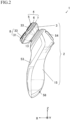
Fig. 2 is a schematic side view of the rotary electric shaver illustrated inFig. 1 . -
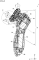
Fig. 3 is a schematic vertical sectional view of the rotary electric shaver illustrated inFig. 2 . -
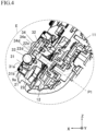
Fig. 4 is an enlarged view of a part surrounded by a broken line inFig. 3 . -
Fig. 5 is a schematic structural development view of a head according to the present embodiment. -
Fig. 6A is a schematic perspective view of a cover,Fig. 6B is a schematic perspective view of a support,Fig. 6C is a schematic perspective view of an outer blade member, andFig. 6D is a schematic perspective view of an inner blade part. - Hereinafter, an embodiment according to the present invention will be described in detail with reference to the drawings. A rotary
electric shaver 1 of the present embodiment has ahead 4 having a plurality ofblade units 5. As illustrated inFig. 1 , as an example, the rotaryelectric shaver 1 includes agrip part 15 gripped by a user, and thehead 4 detachably connected to aconnection part 13 disposed in thegrip part 15. A front surface side of amain body 2 is an operation panel, and apower switch 53 is disposed. As an example, ablade setting base 3 is connected to thegrip part 15 via theconnection part 13, and thehead 4 is configured to be capable of tilting with respect to themain body 2. Here, in order to easily describe a positional relationship of each part of the rotaryelectric shaver 1, directions are indicated by arrows X, Y, and Z in the drawing. When the rotaryelectric shaver 1 is actually used, without being limited to the directions, the rotaryelectric shaver 1 may be used in any desired direction. In all drawings for describing the embodiment, the same reference numerals will be assigned to members having the same function, and repeated description thereof may be omitted in some cases. - As illustrated in
Figs. 1 to 3 , as an example, themain body 2 has thegrip part 15 and theblade setting base 3, and atrimmer 54 is disposed on a back surface side of themain body 2. Amotor 51, abattery 52 which can supply a direct current to themotor 51, and acontroller 55 activated by thepower switch 53 are built in thegrip part 15 in themain body 2. As an example, a configuration is adopted as follows. Apower supply terminal 58 is disposed in a lower part on the back surface side of themain body 2, and power can be supplied to thebattery 52 from an external power source via thepower supply terminal 58. As an example, themotor 51 is connected to a first drivenshaft 11 by afirst drive part 56 having a plurality of gears. A technique in the related art can be applied to thefirst drive part 56. A plurality of second drivenshafts 12 are disposed in theblade setting base 3. As an example, three second drivenshafts 12 are disposed at a predetermined interval. As an example, the first drivenshaft 11 is connected to the second drivenshaft 12 by asecond drive part 57 having a plurality of gears. A technique in the related art can be applied to thesecond drive part 57. - The
head 4 has a settingpart 6 having a plurality ofblade units 5, and ablade frame 7 that holds the settingpart 6. As an example, threeblade units 5 are disposed at a predetermined interval in thehead 4. In thesetting part 6, eachgroove part 6a having a depth which allows swing movement of theblade unit 5 is formed at an intermediate position between theblade unit 5 and theblade unit 5. In a configuration in which the threeblade units 5 are disposed, threegroove parts 6a are formed, and one end of each of thegroove parts 6a is connected in a center of the settingpart 6. The settingpart 6 is configured as follows. The settingpart 6 is pressed up due to a restoring force of a plate-shapedspring 41 disposed in theblade frame 7. -
Fig. 4 is an enlarged view of a part of thehead 4 inFig. 3 which is surrounded by a broken line E.Fig. 5 is a schematic structural development view of thehead 4.Fig. 6A is a perspective view of acover 32 in thehead 4.Fig. 6B is a perspective view of asupport 34 in thehead 4.Fig. 6C is a perspective view of anouter blade member 31 in thehead 4.Fig. 6D is a perspective view of aninner blade part 9 in thehead 4. Anouter blade part 8 is configured to have the annularouter blade member 31, the disk-shapedcover 32, a plurality ofballs 33, and thesupport 34. - Each of the
blade units 5 has theouter blade part 8 and theinner blade part 9. Theouter blade part 8 has an outer shaving surface 31a and an inner sliding contact surface 31b with which ablade edge 9a comes into sliding contact, and has the annular and metal-madeouter blade member 31 in which a plurality ofslits 31c having a size which enables hairs to enter are formed in the circumferential direction. In this invention, examples of the hairs include beards, mustache, whisker, and the like. Theinner blade part 9 has a metal-madeinner blade member 21 in which a plurality of the blade edges 9a are formed in the circumferential direction, and a resin-madebase part 22 joined to theinner blade member 21. Afirst projection part 22d is formed in a center of thebase part 22, and a firsthollow part 22e is formed inside thefirst projection part 22d. A tip part of the second drivenshaft 12 is fitted to the firsthollow part 22e, the second drivenshaft 12 is connected to thebase part 22, and theinner blade member 21 is configured to rotate around an axis P1 of the second drivenshaft 12. A technique in the related art can be applied to theouter blade part 8 and theinner blade part 9. - The disk-shaped and resin-made
cover 32 is disposed inside the annularouter blade member 31. Thecover 32 has a plurality ofcircular windows 32a each having a smaller diameter than the corresponding ball in the plurality ofballs 33, and has a plurality ofpins 32b which are formed to protrude. - A plurality of the
balls 33 are disposed in each of theouter blade members 31. As an example, threeballs 33 are disposed at positions deviated from the axis P1 of the second drivenshaft 12. As an example, the plurality ofballs 33 are made of metal, and is made of stainless steel, aluminum, steel, titanium, a copper alloy, a nickel alloy, or other known metal or alloys. A surface of theballs 33 can be colored by means of plating or by using an anodic oxide film, for example. The plurality ofballs 33 can be made of a resin or ceramics. - A
second projection part 34d is formed in the center of the disk-shaped and resin-madesupport 34, and a plurality of throughholes 34a into which thepins 32b are inserted are formed around thesecond projection part 34d. As an example, the throughhole 34a is set to have a hole diameter which enables thepin 32b to be fitted in a state where thepin 32b is inserted into the throughhole 34a. Thesupport 34 has a plurality ofball receiving holes 34b corresponding to the plurality ofballs 33 on a one-to-one basis. Thesupport 34 has a plurality ofclaw parts 34c protruding from an inner peripheral side of eachball receiving hole 34b at an equal interval in the circumferential direction. Each of theclaw parts 34c is in contact with one of the plurality ofballs 33 to support theball 33 from below. As an example, the number of the disposedclaw parts 34c is three to five. Thecover 32 is fitted and assembled to thesupport 34 in a state where each of theballs 33 is supported from below. A part of eachball 33 surrounded by thecover 32 and thesupport 34 is configured to protrude from thewindow 32a. - Each
ball receiving hole 34b hasdischarge parts 34f respectively formed on both sides of each of theclaw parts 34c. In this manner, even when a shaving waste enters the inside through a gap formed around theball 33 when theball 33 is operated in an upward-downward direction, the entering shaving waste passes through thedischarge part 34f, passes through theinner blade part 9, and is collected in a lower shaving waste discharge area. Accordingly, it is possible to prevent accumulation of the shaving waste which hinders an operation of theball 33. In addition, each of thedischarge parts 34f has a shape in which a position between theclaw parts 34c and theclaw parts 34c which are disposed adjacent to each other in the circumferential direction is enlarged. Accordingly, theclaw part 34c can have a shape which is likely to follow an operation in the upward-downward direction of theball 33. - The
second projection part 34d is formed in the center of the disk-shaped and resin-madesupport 34, and a second hollow part 34e is formed inside thesecond projection part 34d. Thefirst projection part 22d is fitted to the second hollow part 34e, and thecover 32 and thesupport 34 are configured to rotate around the axis P1 of the second drivenshaft 12 in conjunction with rotation of theinner blade member 21. - According to the present invention the rotary
electric shaver 1 is described inclaim 1. - The rotary
electric shaver 1 achieves excellent shaving performance even in a largely undulating area from a chin to a face. - The scope of protection of the current invention is defined by the appended claims.
Claims (7)
- A rotary electric shaver (1), comprising:a main body (2) having a grip part (15) and a blade setting base (3);a motor (51) built in the main body (2) and connected to a first driven shaft (11); anda head (4) connected to the blade setting base (3),wherein in the blade setting base (3), a plurality of second driven shafts (12) are connected to the first driven shaft (11),the head (4) has a setting part (6) in which a plurality of blade units (5) are disposed, and a blade frame (7) that holds the setting part (6),each of the blade units (5) has an outer blade part (8) and an inner blade part (9),the inner blade part (9) has an inner blade member (21) in which a plurality of blade edges (9a) are formed in a circumferential direction, and a base part (22) joined to the inner blade member (21),the second driven shaft (12) is connected to the base part (22), and the inner blade member (21) is configured to rotate around an axis (P1) passing through the second driven shaft (12),the outer blade part (8) has an annular outer blade member having a sliding contact surface with which the blade edge (9a) comes into sliding contact and having a plurality of slits formed in the circumferential direction, a disk-shaped cover (32) disposed inside the annular outer blade member, two to six balls (33) disposed in the outer blade part (8), and a support (34) that supports the two to six balls (33),the cover (32) has two to six windows (32a), whereina part of each of the two to six balls (33) surrounded by the cover (32) and the support (34) protrudes from a corresponding window (32a) of the two to six windows, and whereineach of the two to six windows (32a) has a smaller diameter than the corresponding ball in the two to six balls (33), andall of the two to six balls are disposed at positions deviated from the axis (P1) passing through the second driven shaft (12).
- The rotary electric shaver (1) according to claim 1,
wherein the support (34) has a plurality of ball receiving holes (34b) corresponding to the two to six of balls (33) on a one-to-one basis and a plurality of claw parts (34c) formed at an equal interval in the circumferential direction to protrude from an inner peripheral side of each ball receiving hole (34b), and each of the claw parts (34c) is in contact with one of the two to six balls (33). - The rotary electric shaver (1) according to claim 2,
wherein in each ball receiving hole (34b), discharge parts (34f) are respectively formed on both sides of each of the claw parts (34c). - The rotary electric shaver (1) according to any one of claims 1 to 3,wherein the two to six balls (33) are made of metal,both the cover (32) and the support (34) are made of a resin,the cover (32) is formed so that a plurality of pins (32b) protrude,the support (34) has a plurality of through holes (34a) into which the pins (32b) are inserted, respectively, andthe cover (32) is fitted and assembled to the support (34).
- The rotary electric shaver (1) according to any one of claims 1 to 4,wherein a first projection part (22d) is formed in a center of the base part (22), and a first hollow part (22e) is formed inside the first projection part (22d),a second projection part (34d) is formed in a center of the support (34), and a second hollow part (34e) is formed inside the second projection part (34d), andthe second driven shaft (12) is fitted to the first hollow part (22e), and the first projection part (22d) is fitted to the second hollow part (34e).
- The rotary electric shaver (1) according to any one of claims 1 to 5,wherein three blade units (5) are disposed in the head (4), andin the setting part (6), groove parts (6a) having a depth which allows swing movement of the blade unit (5) are formed at an intermediate position between adjacent blade units (5).
- The rotary electric shaver (1) according to any one of claims 1 to 6,wherein the blade setting base (3) is connected to the grip part (15) via a connection part (13), andthe head (4) is connected to the blade setting base (3) to be capable of tilting with respect to the main body (2).
Applications Claiming Priority (1)
| Application Number | Priority Date | Filing Date | Title |
|---|---|---|---|
| JP2021176037A JP7803683B2 (en) | 2021-10-28 | 2021-10-28 | rotary electric shaver |
Publications (2)
| Publication Number | Publication Date |
|---|---|
| EP4173782A1 EP4173782A1 (en) | 2023-05-03 |
| EP4173782B1 true EP4173782B1 (en) | 2025-04-23 |
Family
ID=83193402
Family Applications (1)
| Application Number | Title | Priority Date | Filing Date |
|---|---|---|---|
| EP22193984.6A Active EP4173782B1 (en) | 2021-10-28 | 2022-09-05 | Rotary electric shaver |
Country Status (4)
| Country | Link |
|---|---|
| US (1) | US12168303B2 (en) |
| EP (1) | EP4173782B1 (en) |
| JP (2) | JP7803683B2 (en) |
| CN (1) | CN116038775A (en) |
Families Citing this family (2)
| Publication number | Priority date | Publication date | Assignee | Title |
|---|---|---|---|---|
| USD912898S1 (en) * | 2017-12-08 | 2021-03-09 | Braun Gmbh | Epilator |
| EP3825078A1 (en) * | 2019-11-19 | 2021-05-26 | Koninklijke Philips N.V. | A shaving unit and an electric shaver having the shaving unit |
Family Cites Families (22)
| Publication number | Priority date | Publication date | Assignee | Title |
|---|---|---|---|---|
| US2221119A (en) * | 1938-07-19 | 1940-11-12 | Ferdinand F Starr | Guard for razors and hair clippers |
| NL8403065A (en) | 1984-10-09 | 1986-05-01 | Philips Nv | SHAVER. |
| JPS61140767U (en) * | 1985-02-20 | 1986-08-30 | ||
| US5103560A (en) * | 1990-05-31 | 1992-04-14 | Grigory Podolsky | Shaving device with dispenser |
| IL119506A0 (en) | 1996-10-28 | 1997-01-10 | Barish Benjamin J | Electrical hair remover device and method |
| DE60109139T2 (en) | 2000-12-06 | 2006-01-19 | Koninklijke Philips Electronics N.V. | shaving |
| WO2003068466A1 (en) * | 2002-02-13 | 2003-08-21 | Matsushita Electric Works, Ltd. | Hair removing device with a lotion applicator |
| WO2004108368A1 (en) | 2003-06-10 | 2004-12-16 | Koninklijke Philips Electronics N.V. | Shaving apparatus |
| US20060064876A1 (en) * | 2004-09-30 | 2006-03-30 | Richard Lee | Razor |
| JP4662239B2 (en) * | 2004-12-03 | 2011-03-30 | 株式会社泉精器製作所 | Rotary electric razor |
| US20090025234A1 (en) * | 2007-07-24 | 2009-01-29 | Vito James Carlucci | Form fitting electric shaver with multiple cutting assemblies |
| JP5472983B2 (en) * | 2009-11-05 | 2014-04-16 | 株式会社泉精器製作所 | Electric razor |
| JP2015070927A (en) | 2013-10-03 | 2015-04-16 | 株式会社泉精器製作所 | Rotary type electric razor |
| US9550303B2 (en) * | 2014-10-07 | 2017-01-24 | Ruairidh Robertson | Shaving device |
| JP6688049B2 (en) * | 2015-11-24 | 2020-04-28 | マクセルイズミ株式会社 | Rotary electric razor and method of manufacturing inner blade of rotary electric razor |
| JP2017136349A (en) | 2016-02-02 | 2017-08-10 | 株式会社泉精器製作所 | Rotary type electric razor and manufacturing method for outer blade of rotary type electric razor |
| CN206717921U (en) | 2017-05-08 | 2017-12-08 | 浙江美森电器有限公司 | Band ball shaver |
| US10513041B2 (en) | 2017-10-26 | 2019-12-24 | HeadBlade, Inc. | Shaving apparatus |
| CN208663871U (en) | 2018-09-04 | 2019-03-29 | 宁波开利控股集团股份有限公司 | A kind of electric shaver of the automatic ball massage of band |
| CN210525159U (en) * | 2019-09-16 | 2020-05-15 | 深圳市加减生活科技有限公司 | Ball formula tool bit group mounting structure |
| JP7457482B2 (en) * | 2019-10-24 | 2024-03-28 | マクセルイズミ株式会社 | rotary electric razor |
| JP7296299B2 (en) * | 2019-10-28 | 2023-06-22 | マクセルイズミ株式会社 | rotary electric razor |
-
2021
- 2021-10-28 JP JP2021176037A patent/JP7803683B2/en active Active
-
2022
- 2022-08-29 US US17/897,559 patent/US12168303B2/en active Active
- 2022-09-05 EP EP22193984.6A patent/EP4173782B1/en active Active
- 2022-10-20 CN CN202211285122.0A patent/CN116038775A/en active Pending
-
2025
- 2025-05-23 JP JP2025086352A patent/JP2025114872A/en active Pending
Also Published As
| Publication number | Publication date |
|---|---|
| JP7803683B2 (en) | 2026-01-21 |
| CN116038775A (en) | 2023-05-02 |
| JP2025114872A (en) | 2025-08-05 |
| US20230132864A1 (en) | 2023-05-04 |
| US12168303B2 (en) | 2024-12-17 |
| EP4173782A1 (en) | 2023-05-03 |
| JP2023065732A (en) | 2023-05-15 |
Similar Documents
| Publication | Publication Date | Title |
|---|---|---|
| EP4173782A1 (en) | Rotary electric shaver | |
| EP3173197B1 (en) | Rotary electric shaver and method of manufacturing inner blade of rotary electric shaver | |
| EP3812111B1 (en) | Rotary electric shaver | |
| EP3115160B1 (en) | Rotary electric shaver | |
| US3797109A (en) | Electric shaver with rockable shaving head | |
| EP1902818B1 (en) | Rotary electric shaver | |
| JPH114980A (en) | Electric shaver | |
| EP3162518B1 (en) | Rotary electric shaver | |
| EP4711102A1 (en) | Rotary electric shaver | |
| EP3815860B1 (en) | Rotary electric shaver | |
| EP4112248A1 (en) | Transmission system for use in a shaving head of an electric shaver | |
| EP4617016A1 (en) | Electric shaver | |
| EP4499358B1 (en) | Adjusting an exposure distance in a hair-cutting unit for a rotary electric shaver | |
| EP4499359B1 (en) | Realizing a defined exposure distance setting in a hair-cutting unit for a rotary electric shaver | |
| CN122071121A (en) | Rotary electric shaver | |
| KR200232201Y1 (en) | A roller type slim electric shaver | |
| JPH0631662U (en) | Electric razor |
Legal Events
| Date | Code | Title | Description |
|---|---|---|---|
| PUAI | Public reference made under article 153(3) epc to a published international application that has entered the european phase |
Free format text: ORIGINAL CODE: 0009012 |
|
| STAA | Information on the status of an ep patent application or granted ep patent |
Free format text: STATUS: THE APPLICATION HAS BEEN PUBLISHED |
|
| AK | Designated contracting states |
Kind code of ref document: A1 Designated state(s): AL AT BE BG CH CY CZ DE DK EE ES FI FR GB GR HR HU IE IS IT LI LT LU LV MC MK MT NL NO PL PT RO RS SE SI SK SM TR |
|
| STAA | Information on the status of an ep patent application or granted ep patent |
Free format text: STATUS: REQUEST FOR EXAMINATION WAS MADE |
|
| 17P | Request for examination filed |
Effective date: 20230804 |
|
| RBV | Designated contracting states (corrected) |
Designated state(s): AL AT BE BG CH CY CZ DE DK EE ES FI FR GB GR HR HU IE IS IT LI LT LU LV MC MK MT NL NO PL PT RO RS SE SI SK SM TR |
|
| STAA | Information on the status of an ep patent application or granted ep patent |
Free format text: STATUS: EXAMINATION IS IN PROGRESS |
|
| 17Q | First examination report despatched |
Effective date: 20240926 |
|
| GRAP | Despatch of communication of intention to grant a patent |
Free format text: ORIGINAL CODE: EPIDOSNIGR1 |
|
| STAA | Information on the status of an ep patent application or granted ep patent |
Free format text: STATUS: GRANT OF PATENT IS INTENDED |
|
| INTG | Intention to grant announced |
Effective date: 20250206 |
|
| GRAS | Grant fee paid |
Free format text: ORIGINAL CODE: EPIDOSNIGR3 |
|
| GRAA | (expected) grant |
Free format text: ORIGINAL CODE: 0009210 |
|
| STAA | Information on the status of an ep patent application or granted ep patent |
Free format text: STATUS: THE PATENT HAS BEEN GRANTED |
|
| P01 | Opt-out of the competence of the unified patent court (upc) registered |
Free format text: CASE NUMBER: APP_8445/2025 Effective date: 20250219 |
|
| AK | Designated contracting states |
Kind code of ref document: B1 Designated state(s): AL AT BE BG CH CY CZ DE DK EE ES FI FR GB GR HR HU IE IS IT LI LT LU LV MC MK MT NL NO PL PT RO RS SE SI SK SM TR |
|
| REG | Reference to a national code |
Ref country code: GB Ref legal event code: FG4D |
|
| REG | Reference to a national code |
Ref country code: CH Ref legal event code: EP |
|
| REG | Reference to a national code |
Ref country code: DE Ref legal event code: R096 Ref document number: 602022013463 Country of ref document: DE |
|
| REG | Reference to a national code |
Ref country code: IE Ref legal event code: FG4D |
|
| REG | Reference to a national code |
Ref country code: NL Ref legal event code: MP Effective date: 20250423 |
|
| PG25 | Lapsed in a contracting state [announced via postgrant information from national office to epo] |
Ref country code: NL Free format text: LAPSE BECAUSE OF FAILURE TO SUBMIT A TRANSLATION OF THE DESCRIPTION OR TO PAY THE FEE WITHIN THE PRESCRIBED TIME-LIMIT Effective date: 20250423 |
|
| REG | Reference to a national code |
Ref country code: AT Ref legal event code: MK05 Ref document number: 1787360 Country of ref document: AT Kind code of ref document: T Effective date: 20250423 |
|
| PG25 | Lapsed in a contracting state [announced via postgrant information from national office to epo] |
Ref country code: FI Free format text: LAPSE BECAUSE OF FAILURE TO SUBMIT A TRANSLATION OF THE DESCRIPTION OR TO PAY THE FEE WITHIN THE PRESCRIBED TIME-LIMIT Effective date: 20250423 Ref country code: PT Free format text: LAPSE BECAUSE OF FAILURE TO SUBMIT A TRANSLATION OF THE DESCRIPTION OR TO PAY THE FEE WITHIN THE PRESCRIBED TIME-LIMIT Effective date: 20250825 Ref country code: ES Free format text: LAPSE BECAUSE OF FAILURE TO SUBMIT A TRANSLATION OF THE DESCRIPTION OR TO PAY THE FEE WITHIN THE PRESCRIBED TIME-LIMIT Effective date: 20250423 |
|
| PGFP | Annual fee paid to national office [announced via postgrant information from national office to epo] |
Ref country code: DE Payment date: 20250919 Year of fee payment: 4 |
|
| REG | Reference to a national code |
Ref country code: LT Ref legal event code: MG9D |
|
| PG25 | Lapsed in a contracting state [announced via postgrant information from national office to epo] |
Ref country code: NO Free format text: LAPSE BECAUSE OF FAILURE TO SUBMIT A TRANSLATION OF THE DESCRIPTION OR TO PAY THE FEE WITHIN THE PRESCRIBED TIME-LIMIT Effective date: 20250723 Ref country code: GR Free format text: LAPSE BECAUSE OF FAILURE TO SUBMIT A TRANSLATION OF THE DESCRIPTION OR TO PAY THE FEE WITHIN THE PRESCRIBED TIME-LIMIT Effective date: 20250724 |
|
| PG25 | Lapsed in a contracting state [announced via postgrant information from national office to epo] |
Ref country code: PL Free format text: LAPSE BECAUSE OF FAILURE TO SUBMIT A TRANSLATION OF THE DESCRIPTION OR TO PAY THE FEE WITHIN THE PRESCRIBED TIME-LIMIT Effective date: 20250423 |
|
| PG25 | Lapsed in a contracting state [announced via postgrant information from national office to epo] |
Ref country code: BG Free format text: LAPSE BECAUSE OF FAILURE TO SUBMIT A TRANSLATION OF THE DESCRIPTION OR TO PAY THE FEE WITHIN THE PRESCRIBED TIME-LIMIT Effective date: 20250423 |
|
| PG25 | Lapsed in a contracting state [announced via postgrant information from national office to epo] |
Ref country code: HR Free format text: LAPSE BECAUSE OF FAILURE TO SUBMIT A TRANSLATION OF THE DESCRIPTION OR TO PAY THE FEE WITHIN THE PRESCRIBED TIME-LIMIT Effective date: 20250423 |
|
| PG25 | Lapsed in a contracting state [announced via postgrant information from national office to epo] |
Ref country code: AT Free format text: LAPSE BECAUSE OF FAILURE TO SUBMIT A TRANSLATION OF THE DESCRIPTION OR TO PAY THE FEE WITHIN THE PRESCRIBED TIME-LIMIT Effective date: 20250423 |
|
| PGFP | Annual fee paid to national office [announced via postgrant information from national office to epo] |
Ref country code: FR Payment date: 20250922 Year of fee payment: 4 |
|
| PG25 | Lapsed in a contracting state [announced via postgrant information from national office to epo] |
Ref country code: RS Free format text: LAPSE BECAUSE OF FAILURE TO SUBMIT A TRANSLATION OF THE DESCRIPTION OR TO PAY THE FEE WITHIN THE PRESCRIBED TIME-LIMIT Effective date: 20250723 |
|
| PG25 | Lapsed in a contracting state [announced via postgrant information from national office to epo] |
Ref country code: IS Free format text: LAPSE BECAUSE OF FAILURE TO SUBMIT A TRANSLATION OF THE DESCRIPTION OR TO PAY THE FEE WITHIN THE PRESCRIBED TIME-LIMIT Effective date: 20250823 |
|
| PG25 | Lapsed in a contracting state [announced via postgrant information from national office to epo] |
Ref country code: LV Free format text: LAPSE BECAUSE OF FAILURE TO SUBMIT A TRANSLATION OF THE DESCRIPTION OR TO PAY THE FEE WITHIN THE PRESCRIBED TIME-LIMIT Effective date: 20250423 |
|
| PG25 | Lapsed in a contracting state [announced via postgrant information from national office to epo] |
Ref country code: DK Free format text: LAPSE BECAUSE OF FAILURE TO SUBMIT A TRANSLATION OF THE DESCRIPTION OR TO PAY THE FEE WITHIN THE PRESCRIBED TIME-LIMIT Effective date: 20250423 Ref country code: SM Free format text: LAPSE BECAUSE OF FAILURE TO SUBMIT A TRANSLATION OF THE DESCRIPTION OR TO PAY THE FEE WITHIN THE PRESCRIBED TIME-LIMIT Effective date: 20250423 |
|
| PG25 | Lapsed in a contracting state [announced via postgrant information from national office to epo] |
Ref country code: CZ Free format text: LAPSE BECAUSE OF FAILURE TO SUBMIT A TRANSLATION OF THE DESCRIPTION OR TO PAY THE FEE WITHIN THE PRESCRIBED TIME-LIMIT Effective date: 20250423 |
|
| PG25 | Lapsed in a contracting state [announced via postgrant information from national office to epo] |
Ref country code: EE Free format text: LAPSE BECAUSE OF FAILURE TO SUBMIT A TRANSLATION OF THE DESCRIPTION OR TO PAY THE FEE WITHIN THE PRESCRIBED TIME-LIMIT Effective date: 20250423 |
|
| REG | Reference to a national code |
Ref country code: DE Ref legal event code: R097 Ref document number: 602022013463 Country of ref document: DE |
|
| PG25 | Lapsed in a contracting state [announced via postgrant information from national office to epo] |
Ref country code: SK Free format text: LAPSE BECAUSE OF FAILURE TO SUBMIT A TRANSLATION OF THE DESCRIPTION OR TO PAY THE FEE WITHIN THE PRESCRIBED TIME-LIMIT Effective date: 20250423 |
|
| PG25 | Lapsed in a contracting state [announced via postgrant information from national office to epo] |
Ref country code: IT Free format text: LAPSE BECAUSE OF FAILURE TO SUBMIT A TRANSLATION OF THE DESCRIPTION OR TO PAY THE FEE WITHIN THE PRESCRIBED TIME-LIMIT Effective date: 20250423 |
|
| PLBE | No opposition filed within time limit |
Free format text: ORIGINAL CODE: 0009261 |
|
| STAA | Information on the status of an ep patent application or granted ep patent |
Free format text: STATUS: NO OPPOSITION FILED WITHIN TIME LIMIT |
|
| REG | Reference to a national code |
Ref country code: CH Ref legal event code: L10 Free format text: ST27 STATUS EVENT CODE: U-0-0-L10-L00 (AS PROVIDED BY THE NATIONAL OFFICE) Effective date: 20260304 |
|
| PG25 | Lapsed in a contracting state [announced via postgrant information from national office to epo] |
Ref country code: RO Free format text: LAPSE BECAUSE OF FAILURE TO SUBMIT A TRANSLATION OF THE DESCRIPTION OR TO PAY THE FEE WITHIN THE PRESCRIBED TIME-LIMIT Effective date: 20250423 |
|
| 26N | No opposition filed |
Effective date: 20260126 |
|
| REG | Reference to a national code |
Ref country code: CH Ref legal event code: H13 Free format text: ST27 STATUS EVENT CODE: U-0-0-H10-H13 (AS PROVIDED BY THE NATIONAL OFFICE) Effective date: 20260425 |