EP4173766A1 - Vorrichtung und verfahren zum programmieren und/oder betreiben einer beweglichen maschine, insbesondere eines roboters - Google Patents
Vorrichtung und verfahren zum programmieren und/oder betreiben einer beweglichen maschine, insbesondere eines roboters Download PDFInfo
- Publication number
- EP4173766A1 EP4173766A1 EP21205352.4A EP21205352A EP4173766A1 EP 4173766 A1 EP4173766 A1 EP 4173766A1 EP 21205352 A EP21205352 A EP 21205352A EP 4173766 A1 EP4173766 A1 EP 4173766A1
- Authority
- EP
- European Patent Office
- Prior art keywords
- machine
- movement
- configuration data
- section
- safety
- Prior art date
- Legal status (The legal status is an assumption and is not a legal conclusion. Google has not performed a legal analysis and makes no representation as to the accuracy of the status listed.)
- Granted
Links
Images

Classifications
-
- B—PERFORMING OPERATIONS; TRANSPORTING
- B25—HAND TOOLS; PORTABLE POWER-DRIVEN TOOLS; MANIPULATORS
- B25J—MANIPULATORS; CHAMBERS PROVIDED WITH MANIPULATION DEVICES
- B25J9/00—Program-controlled manipulators
- B25J9/16—Program controls
- B25J9/1674—Program controls characterised by safety, monitoring, diagnostic
-
- B—PERFORMING OPERATIONS; TRANSPORTING
- B25—HAND TOOLS; PORTABLE POWER-DRIVEN TOOLS; MANIPULATORS
- B25J—MANIPULATORS; CHAMBERS PROVIDED WITH MANIPULATION DEVICES
- B25J9/00—Program-controlled manipulators
- B25J9/16—Program controls
- B25J9/1674—Program controls characterised by safety, monitoring, diagnostic
- B25J9/1676—Avoiding collision or forbidden zones
-
- G—PHYSICS
- G05—CONTROLLING; REGULATING
- G05B—CONTROL OR REGULATING SYSTEMS IN GENERAL; FUNCTIONAL ELEMENTS OF SUCH SYSTEMS; MONITORING OR TESTING ARRANGEMENTS FOR SUCH SYSTEMS OR ELEMENTS
- G05B19/00—Program-control systems
- G05B19/02—Program-control systems electric
- G05B19/18—Numerical control [NC], i.e. automatically operating machines, in particular machine tools, e.g. in a manufacturing environment, so as to execute positioning, movement or co-ordinated operations by means of program data in numerical form
- G05B19/406—Numerical control [NC], i.e. automatically operating machines, in particular machine tools, e.g. in a manufacturing environment, so as to execute positioning, movement or co-ordinated operations by means of program data in numerical form characterised by monitoring or safety
- G05B19/4061—Avoiding collision or forbidden zones
-
- G—PHYSICS
- G05—CONTROLLING; REGULATING
- G05B—CONTROL OR REGULATING SYSTEMS IN GENERAL; FUNCTIONAL ELEMENTS OF SUCH SYSTEMS; MONITORING OR TESTING ARRANGEMENTS FOR SUCH SYSTEMS OR ELEMENTS
- G05B2219/00—Program-control systems
- G05B2219/30—Nc systems
- G05B2219/40—Robotics, robotics mapping to robotics vision
- G05B2219/40607—Fixed camera to observe workspace, object, workpiece, global
-
- G—PHYSICS
- G05—CONTROLLING; REGULATING
- G05B—CONTROL OR REGULATING SYSTEMS IN GENERAL; FUNCTIONAL ELEMENTS OF SUCH SYSTEMS; MONITORING OR TESTING ARRANGEMENTS FOR SUCH SYSTEMS OR ELEMENTS
- G05B2219/00—Program-control systems
- G05B2219/30—Nc systems
- G05B2219/49—Nc machine tool, till multiple
- G05B2219/49137—Store working envelop, limit, allowed zone
-
- G—PHYSICS
- G05—CONTROLLING; REGULATING
- G05B—CONTROL OR REGULATING SYSTEMS IN GENERAL; FUNCTIONAL ELEMENTS OF SUCH SYSTEMS; MONITORING OR TESTING ARRANGEMENTS FOR SUCH SYSTEMS OR ELEMENTS
- G05B2219/00—Program-control systems
- G05B2219/30—Nc systems
- G05B2219/49—Nc machine tool, till multiple
- G05B2219/49142—Shut off power, stop if outside working zone
Definitions
- the invention relates to a device and a method for programming and/or operating a mobile machine, in particular a robot.
- a large number of applications of dangerous moving machines e.g. robots or driverless transport vehicles (AGV) are known, in which man and machine share a common workspace.
- Holistic methods of risk minimization are used to minimize the risk of accidents or injuries with structural, technical and/or organizational measures regarding the consideration of the overall application.
- the EP3189947A1 describes a method for configuring and operating a monitored automated work cell, the work cell having at least one dangerous machine and at least one monitoring device.
- Machine room data that define a working area of the machine is transmitted to a configuration device for the monitoring device and protective area data is created on the basis of the machine room data, so that the protective area data define a protective area of the monitoring device that fully or partially corresponds to the working area of the machine or is larger than the working area .
- the shelter data are transmitted to the monitoring device so that the monitoring device monitors the shelter. This is also a configuration of a robot application that requires appropriately trained personnel.
- the invention is based on the basic idea of identifying an unsafe movement section in a movement sequence of a moving machine that has a large number of movement sections.
- a device according to the invention is initially set up to receive configuration data of the mobile machine and configuration data of at least one safety sensor.
- the configuration data of the mobile machine can be, for example, its dimensions, movement axes, movement speeds, parameters of the reaction and braking behavior or working areas of the machine, whereby the working areas can include all spatial points that can be reached by the mobile machine during operation .
- the configuration data of the moving machine can also include information about an environment of the machine, for example positions and geometries of static objects in the environment of the machine, such as walls or conveyor systems.
- configuration data can also include the dimensions or dimensions of the working area of the robot with the component picked up.
- the configuration data can correspondingly include the dimensions or the dimensions of the working area of the robot with the respectively mounted tool.
- Dimensions of the machine or the components can be in the form of CAD data, for example.
- the configuration data of the at least one safety sensor can in particular be dimensions of a surveillance area of the safety sensor, ie the spatial dimensions of the area in which the safety sensor can detect objects.
- a large number of safety sensors with overlapping monitoring areas are used to monitor a working area of a mobile machine.
- Safety sensors can also be arranged on the mobile machine itself, with their monitoring ranges being able to change when the machine moves.
- Such movement-dependent dimensions of surveillance areas can also be part of the configuration data of the safety sensor.
- the device according to the invention is also set up to receive a planned movement sequence of the moving machine, the movement sequence having a large number of movement sections.
- a movement section can be, for example, a distance between two waypoints along which the machine or a part of it, such as a robot arm or a gripper located on the robot arm, moves.
- the movement sequence can be programmed by operating elements on a terminal of a control unit of the mobile machine, by means of manual guidance of the machine or a part of the machine by an operator, or by a combination of programming and manual guidance. Alternatively, a movement sequence that has already been created can also be loaded into a memory of the machine's control unit.
- the device is set up to identify at least one unsafe movement section using the configuration data of the machine and the configuration data of the at least one safety sensor.
- a movement section of the moving machine in which a predetermined safety criterion is violated is to be understood as a non-safe movement section.
- the device according to the invention is therefore set up to check whether the movement sections of the movement sequence correspond to one or more specified safety criteria.
- a safety criterion can be, for example, that the mobile machine or part of it does not leave the monitoring area of the safety sensors moved.
- a further safety criterion can be that a movement speed of the machine or part of the machine does not exceed a predetermined movement speed.
- Minimum distances from objects in the vicinity of the machine can also represent a safety criterion, and these minimum distances can also depend on the speed at which the machine or a part of the machine is moving.
- the invention has the advantage that possible dangers from a moving machine or a part of the machine can already be recognized during a learning process of a movement sequence of the machine and thereby eliminated or at least significantly reduced. In particular, it is not necessary to resort to personnel specially trained in safety technology for planning the movement sequence, since the movement sequence of the machine is checked for unsafe movement sections by the device according to the invention itself.
- a division of the planned motion sequence into a large number of motion sections can already take place when the motion sequence is programmed.
- the planned movement sequence then has corresponding information, and the device can be set up to use this information when checking the movement sequence.
- the device can be designed to divide the planned movement sequence into a large number of movement sections according to predetermined criteria. For example, it can be divided according to the distance covered by a defined point on the machine or according to the duration of the movement.
- the device according to the invention can preferably have an interface for outputting an identified unsafe movement section.
- the unsafe movement section can be indicated to the operator by an output device connected to the interface, for example on a terminal of a control unit of the mobile machine or by illuminated indications on one or more safety sensors or on the mobile machine itself.
- the device according to the invention can preferably be part of a control unit of a mobile machine, wherein the device and/or the control unit can be set up to slow down or stop the movement sequence when the machine is executing the movement sequence when an unsafe movement section is reached.
- a teach-in phase of a moving machine can be additionally secured.
- This embodiment can be used particularly advantageously for manual planning of the motion sequence, since the operator can see the unsafe motion section directly on the machine and can define a motion sequence that corresponds to the specified safety criteria by tracking the machine.
- the device can be designed in such a way that configuration data of the moving machine and/or configuration data of the at least one safety sensor can only be entered and/or changed or received after successful authentication. Authentication can take place, for example, by means of a password query.
- configuration data of the mobile machine and/or configuration data of the at least one safety sensor which are received by a control unit, can have an authentication key, with the device being set up to check the validity of the configuration data using the authentication key. This can ensure that the configuration data of the moving machine and/or the configuration data of the at least one safety sensor can only be entered and/or changed, for example, by personnel who have been specially trained in safety technology, or that only valid configuration data can be received.
- the device can have a memory unit comprising several memory sections.
- the movement can be stored in a first memory section and the configuration data of the mobile machine and/or the configuration data of the at least one safety sensor in a second memory section different from the first memory section.
- the second memory section can preferably have a stronger access restriction than the first memory section. In this way, manipulation of the configuration data of the machine and/or the configuration data of the at least one safety sensor can be made more difficult or prevented.
- the device according to the invention can be used particularly advantageously with sensor protection of a working area of a tool mounted on a robot flange. There is a risk of crushing on the robot or on the robot tool as early as the teach-in phase of a movement sequence.
- the method according to the invention can be implemented as a computer program with program code means for carrying out the method.
- the computer program can be stored on a storage medium.
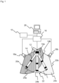
- FIG 1 shows a schematic top view of an exemplary application of a device 10 according to the invention.
- a robot 12 with a robot arm 14 and a control unit 16 is monitored by a first safety sensor 18a and a second safety sensor 18b, each of which has a first monitoring area 20a and a second monitoring area 20b .
- a planned movement sequence 22 of the robot arm 14 is represented by dashed positions 14a, 14b of the robot arm 14, with the robot arm 14 moving from left to right as a result of a counterclockwise rotation of the robot 12.
- the movement sequence 22 is divided into three movement sections 24a, 24b, 24c.
- Device 10 is set up to receive and to identify a movement section 24b on the basis of the information received, which violates the predetermined safety criterion.
- the robot arm 14 moves in a movement section 24b outside the monitoring areas 20a, 20b of the safety sensors 18a, 18b, which means there is a potential safety risk.
- the corresponding movement section 24b would therefore violate a safety criterion which requires that the robot arm 14 only moves within the monitored areas 20a, 20b of the safety sensors 18a, 18b.
- the device 10 can transmit the information about the unsafe movement section 24b via an interface to a terminal 26 of the control unit 16 of the robot.
- the device 10 is shown purely as an example as a separate module.
- the control unit 16 or the terminal 26 can also include the device 10 .
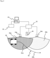
- FIG 2 shows a further exemplary application of a device 30 according to the invention in a schematic top view.
- a safety controller 32 is connected to a first safety sensor 34a and a second safety sensor 34b, which each have a first monitoring area 36a and a second monitoring area 36b.
- the security sensors 34a, 34b monitor a driverless transport system (DTS) 38.
- the device 30 is set up to receive dimensions and a planned movement sequence 40 of the driverless transport system 38, as well as the dimension of the monitored areas 36a, 36b of the safety sensors 34a, 34b and from the received data from the movement sections 42a, 42b of the movement sequence 40 to identify movement sections that violate a predetermined safety criterion.
- DTS driverless transport system
- a movement section 42b is outside of the monitoring areas 36a, 36b of the safety sensors, and would therefore violate a safety criterion which requires that the driverless transport system 38 may only move within the monitoring areas 36a, 36b of the safety sensors 34a, 34b.
- the device 30 can transmit the information about the non-safe movement section 24b to a terminal 44 of the safety controller 32 via an interface.
- the information about the non-safe movement section 24b can be provided via an illuminated sign, for example a signal light 46 .
- the device 30 is shown purely as an example as a separate module.
- the control unit 32 or the terminal 44 can also include the device 30 .
- figure 3 shows an exemplary flow chart 50 of a method according to the invention for programming and/or operating a movable machine.
- a first step 52 the configuration data of the mobile machine defined during an installation and/or configuration process by personnel specially trained in safety technology and configuration data of at least one safety sensor are received, for example by directly entering the configuration data or reading the configuration data from a memory of a control unit of a mobile machine and/or from a safety controller.
- safety criteria for the operation of the mobile machine are determined, also by personnel specially trained in safety technology, for example the determination that no part of the mobile machine may leave a monitoring area of the at least one safety sensor, that the mobile machine or a part given by her speed and/or acceleration, or that the moving machine or part of it must maintain specified minimum distances to objects in the vicinity, for example to minimize the risk of crushing.
- third step 56 a planned movement sequence of the mobile machine is received, the movement sequence comprising a large number of movement sections.
- the movement sequence can be generated either by directly entering the movement sections or by manually guiding the machine, for example by manually guiding a robot arm.
- the planned sequence of movements can be programmed or taught in by the operating personnel; specially trained safety personnel are not required for this step.
- movement sections that violate one or more of the specified safety criteria are identified, for example by checking whether the moving machine is in a monitoring area of a safety sensor, whether a specified speed of the machine or a part of it is not exceeded or minimum distances to objects in the vicinity are observed.
- the check 60 of the planned movement sequence shows that it has at least one non-safe movement section
- information about the non-safe movement section can be output in an output step 62 .
- the planned movement sequence can be transmitted to a control unit of the machine in a transmission step 64 .
- a planned movement sequence can also be transmitted to the control unit of the machine if it has unsafe movement sections, with the planned movement sequence being transmitted either with information about the unsafe movement section or only up to the unsafe movement section will, so the machine is slowed down or stopped when executing the planned movement sequence before reaching the non-safe movement section.
Landscapes
- Engineering & Computer Science (AREA)
- Robotics (AREA)
- Mechanical Engineering (AREA)
- Human Computer Interaction (AREA)
- Manufacturing & Machinery (AREA)
- Physics & Mathematics (AREA)
- General Physics & Mathematics (AREA)
- Automation & Control Theory (AREA)
- Manipulator (AREA)
- Numerical Control (AREA)
Abstract
Description
- Die Erfindung betrifft eine Vorrichtung und ein Verfahren zum Programmieren und/oder Betreiben einer beweglichen Maschine, insbesondere eines Roboters.
- Es sind eine Vielzahl Anwendungen von gefahrbringenden beweglichen Maschinen (z.B. Robotern oder fahrerlosen Transportfahrzeugen (FTF, englisch Automated Guided Vehicle, AGV) bekannt, bei denen sich Mensch und Maschine einen gemeinsamen Arbeitsraum teilen. Zur Minimierung von Unfall- oder Verletzungsrisiken werden ganzheitliche Methoden der Risikominimierung mit baulichen, technischen, und/oder organisatorischen Maßnahmen über die Betrachtung der Gesamtanwendung verwendet.
- Ein relevanter Anteil von Unfällen mit gefahrbringenden Maschinen kann jedoch bereits während der Installations-, der Konfigurations- und der Einlernphase des Systems auftreten. Um derartige Unfälle zu verhindern, werden in der Regel alle Aufgaben zur Installation und Konfiguration und Einlernen von Bewegungsabläufen des Systems durch speziell geschultes Personal durchgeführt. Um weiterhin zu verhindern, dass ungeschultes Personal Konfigurationseinstellungen oder Bewegungsabläufe verändert oder gar selbst Installations-, Konfigurations- oder Einlernaufgaben ausführt, erfolgt in der Regel ein Passwortschutz der entsprechenden Programmteile einer Steuereinheit des Systems.
- Aus der
EP2378445A1 ist ein Simulationsverfahren zur sicherheitstechnischen Planung einer industriellen Anlage mit Gefährdungspotential bekannt, wobei Schutzfelder/Funktionen an eine Roboteranwendung angepasst werden. Dazu müssen zum einen die Roboteranwendungen priori bekannt sein, zum anderen muss die Planung durch entsprechend geschulte Steuerungstechniker erfolgen. - Die
EP3189947A1 beschreibt ein Verfahren zum Konfigurieren und zum Betreiben einer überwachten automatisierten Arbeitszelle, wobei die Arbeitszelle zumindest eine gefahrbringende Maschine und zumindest eine Überwachungseinrichtung aufweist. Maschinenraumdaten, die einen Arbeitsraum der Maschine definieren werden an eine Konfigurationsvorrichtung für die Überwachungseinrichtung übermittelt und Schutzraumdaten anhand der Maschinenraumdaten erstellt, so dass die Schutzraumdaten einen Schutzraum der Überwachungseinrichtung definieren, der dem Arbeitsraum der Maschine vollständig oder teilweise dem Arbeitsraum entspricht oder größer als der Arbeitsraum ist. Die Schutzraumdaten werden an die Überwachungseinrichtung übertragen, so dass die Überwachungseinrichtung den Schutzraum überwacht. Auch hier handelt es sich um eine Konfiguration einer Roboteranwendung, zu der entsprechend geschultes Personal benötigt wird. - Häufige Änderungen in Produktionsabläufen, beispielsweise bedingt durch geringe Losgrößen oder kundenspezifische Anforderungen erfordern jedoch eine sichere, unkomplizierte und flexible Anpassung von Bewegungsabläufen beweglicher Maschinen insbesondere im Produktionsumfeld. Nachteilig ist hierbei, dass, wie oben beschrieben, stets auf besonders geschultes Personal zurückgegriffen werden muss, wodurch die Produktionskosten erhöht werden oder es zu Verzögerungen im Produktionsablauf kommt, da entsprechend geschultes Personal beispielsweise aufgrund von Fachkräftemangel häufig nicht in ausreichender Zahl zur Verfügung steht.
- Es ist daher Aufgabe der Erfindung, eine Vorrichtung zum Programmieren und/oder Betreiben einer beweglichen Maschine, beispielsweise eines Roboters zur Verfügung zu stellen, um mögliche Gefahren insbesondere während eines Einlernvorgangs der Maschine zu eliminieren oder zumindest signifikant zu reduzieren.
- Diese Aufgabe wird durch eine Vorrichtung und ein Verfahren zum Programmieren und/oder Betreiben einer beweglichen Maschine, insbesondere eines Roboters nach den Ansprüchen 1 beziehungsweise 9 und ein entsprechendes Computerprogramm nach Anspruch 14 gelöst.
- Die Erfindung geht von dem Grundgedanken aus, in einem eine Vielzahl von Bewegungsabschnitten aufweisenden Bewegungsablauf einer beweglichen Maschine einen nicht sicheren Bewegungsabschnitt zu identifizieren. Dazu ist eine erfindungsgemäße Vorrichtung zunächst dazu eingerichtet, Konfigurationsdaten der beweglichen Maschine und Konfigurationsdaten wenigstens eines Sicherheitssensors zu empfangen.
- Bei den Konfigurationsdaten der beweglichen Maschine kann es sich beispielsweise um deren Abmessungen, Bewegungsachsen, Bewegungsgeschwindigkeiten, Parameter des Reaktions- und Bremsverhaltens oder Arbeitsbereiche der Maschine handeln, wobei die Arbeitsbereiche alle Raumpunkte umfassen können, die während des Betriebs der beweglichen Maschine durch diese erreicht werden können. Die Konfigurationsdaten der beweglichen Maschine können auch Information über eine Umgebung der Maschine, beispielsweise Positionen und Geometrien von statischen Objekten im Umfeld der Maschine wie Wände oder Förderanlagen, umfassen.
- Handelt es sich bei der Maschine beispielsweise um einen Roboter, der dazu eingerichtet ist, Bauteile an einem Ort aufzunehmen und an einem anderen Ort abzulegen, so können Konfigurationsdaten auch die Abmessungen beziehungsweise Dimensionen des Arbeitsbereichs des Roboters mit aufgenommenem Bauteil umfassen. Bei Robotern, bei denen an einem Roboterflansch unterschiedliche Werkzeuge montiert sein können, können die Konfigurationsdaten entsprechend die Abmessungen beziehungsweise die Dimensionen des Arbeitsbereichs des Roboters mit dem jeweils montierten Werkzeug umfassen. Abmessungen der Maschine beziehungsweise der Bauteile können beispielsweise in Form von CAD-Daten vorliegen.
- Bei den Konfigurationsdaten des wenigstens einen Sicherheitssensors kann es sich insbesondere um Dimensionen eines Überwachungsbereichs des Sicherheitssensors handeln, also die räumlichen Dimensionen des Bereichs, in dem der Sicherheitssensor Objekte erfassen kann. In der Regel werden zur Überwachung eines Arbeitsbereichs einer beweglichen Maschine eine Vielzahl von Sicherheitssensoren mit überlappenden Überwachungsbereichen eingesetzt. Sicherheitssensoren können auch an der beweglichen Maschine selbst angeordnet sein, wobei sich deren Überwachungsbereiche bei einer Bewegung der Maschine ändern können. Derartige bewegungsabhängige Dimensionen von Überwachungsbereichen können ebenfalls Bestandteil der Konfigurationsdaten des Sicherheitssensors sein.
- Die erfindungsgemäße Vorrichtung ist weiterhin dazu eingerichtet, einen geplanten Bewegungsablauf der beweglichen Maschine zu empfangen, wobei der Bewegungsablauf eine Vielzahl von Bewegungsabschnitten aufweist. Ein Bewegungsabschnitt kann beispielsweise eine Strecke zwischen zwei Wegpunkten sein, entlang denen sich die Maschine beziehungsweise ein Teil von ihr, wie beispielsweise ein Roboterarm oder ein am Roboterarm befindlicher Greifer, bewegt. Der Bewegungsablauf kann durch Bedienelemente auf einem Terminal einer Steuereinheit der beweglichen Maschine programmiert werden, mittels Handführung der Maschine oder eines Teils der Maschine durch einen Bediener erfolgen, oder durch Kombination von Programmierung und Handführung erstellt werden. Alternativ kann auch ein bereits erstellter Bewegungsablauf in einen Speicher der Steuereinheit der Maschine geladen werden.
- Erfindungsgemäß ist die Vorrichtung dazu eingerichtet, unter Verwendung der Konfigurationsdaten der Maschine und der Konfigurationsdaten des wenigstens einen Sicherheitssensors wenigstens einen nicht sicheren Bewegungsabschnitt zu identifizieren. Als nicht sicherer Bewegungsabschnitt ist ein Bewegungsabschnitt der beweglichen Maschine zu verstehen bei dem ein vorgegebenes Sicherheitskriterium verletzt wird. Die erfindungsgemäße Vorrichtung ist also dazu eingerichtet, für die Bewegungsabschnitte des Bewegungsablaufs zu prüfen, ob diese einem oder mehreren vorgegebenen Sicherheitskriterien entsprechen.
- Ein Sicherheitskriterium kann beispielsweise sein, dass sich die bewegliche Maschine beziehungsweise ein Teil von ihr nicht aus dem Überwachungsbereich der Sicherheitssensoren bewegt. Ein weiteres Sicherheitskriterium kann sein, dass eine Bewegungsgeschwindigkeit der Maschine oder eines Teils der Maschine eine vorgegebene Bewegungsgeschwindigkeit nicht überschreitet. Auch Mindestabstände zu Objekten in der Umgebung der Maschine können ein Sicherheitskriterium darstellen, wobei diese Mindestabstände auch von einer Bewegungsgeschwindigkeit der Maschine oder eines Teils der Maschine abhängig sein können.
- Die Erfindung hat den Vorteil, dass mögliche Gefahren durch eine bewegliche Maschine oder einen Teil der Maschine bereits während eines Einlernvorgangs eines Bewegungsablaufs der Maschine erkannt und dadurch eliminiert oder zumindest signifikant reduziert werden können. Insbesondere muss für die Planung des Bewegungsablaufs nicht auf sicherheitstechnisch speziell geschultes Personal zurückgegriffen werden, da eine Überprüfung des Bewegungsablaufs der Maschine auf nicht sichere Bewegungsabschnitte durch die erfindungsgemäße Vorrichtung selbst erfolgt.
- Eine Aufteilung des geplanten Bewegungsablaufs in eine Vielzahl von Bewegungsabschnitte kann bereits bei der Programmierung des Bewegungsablaufs erfolgen. Der geplante Bewegungsablauf weist dann entsprechende Informationen auf, wobei die Vorrichtung dazu eingerichtet sein kann, diese Information bei der Überprüfung des Bewegungsablaufes zu verwenden. Alternativ kann die Vorrichtung dazu ausgebildet sein, den geplanten Bewegungsablauf gemäß vorgegebenen Kriterien in eine Vielzahl von Bewegungsabschnitte aufzuteilen. Beispielsweise kann eine Aufteilung nach zurückgelegter Strecke eines definierten Punktes der Maschine oder nach Dauer der Bewegung erfolgen.
- Die erfindungsgemäße Vorrichtung kann bevorzugt eine Schnittstelle zum Ausgeben eines identifizierten nicht sicheren Bewegungsabschnitts aufweisen. Der nicht sichere Bewegungsabschnitt kann dem Bediener von einem mit der Schnittstelle verbundenen Ausgabegerät angezeigt werden, beispielsweise auf einem Terminal einer Steuereinheit der beweglichen Maschine oder durch Leuchthinweise an einem oder mehreren Sicherheitssensoren oder an der beweglichen Maschine selbst.
- Dadurch wird dem Bediener die Erkennung nicht sicherer Bewegungsabschnitte erleichtert.
- Die erfindungsgemäße Vorrichtung kann bevorzugt Teil einer Steuereinheit einer beweglichen Maschine sein, wobei die Vorrichtung und/oder die Steuereinheit dazu eingerichtet sein können, bei Ausführung des Bewegungsablaufs durch die Maschine den Bewegungsablauf bei Erreichen eines nicht sicheren Bewegungsabschnitts zu verlangsamen oder zu stoppen. Dadurch kann eine Einlernphase einer beweglichen Maschine zusätzlich abgesichert werden. Diese Ausführungsform kann besonders vorteilhaft bei einer handgeführten Planung des Bewegungsablaufs zur Anwendung kommen, da der Bediener unmittelbar an der Maschine den nicht sicheren Bewegungsabschnitt erkennen kann und durch Nachführen der Maschine einen Bewegungsablauf definieren kann, der den vorgegebenen Sicherheitskriterien entspricht.
- Die Vorrichtung kann derart ausgebildet sein, dass eine Eingabe und/oder Änderung beziehungsweise der Empfang von Konfigurationsdaten der beweglichen Maschine und/oder Konfigurationsdaten des wenigstens einen Sicherheitssensors erst nach einer erfolgreichen Authentifizierung möglich ist. Eine Authentifizierung kann beispielsweise durch eine Passwortabfrage erfolgen. Alternativ können Konfigurationsdaten der beweglichen Maschine und/oder Konfigurationsdaten des wenigstens einen Sicherheitssensors, die von einer Steuereinheit empfangen werden einen Authentifizierungsschlüssel aufweisen, wobei die Vorrichtung dazu eingerichtet ist eine Gültigkeit der Konfigurationsdaten anhand des Authentifizierungsschlüssels zu prüfen. Dadurch kann gewährleistet werden, dass die Konfigurationsdaten der beweglichen Maschine und/oder die Konfigurationsdaten des wenigstens einen Sicherheitssensors beispielsweise nur von sicherheitstechnisch speziell geschultem Personal eingegeben und/oder geändert beziehungsweise nur gültige Konfigurationsdaten empfangen werden können.
- In einer Ausführungsform der Erfindung kann die Vorrichtung eine mehrere Speicherabschnitte umfassende Speichereinheit aufweisen. Der Bewegungsablauf kann dabei in einem ersten Speicherabschnitt gespeichert sein und die Konfigurationsdaten der beweglichen Maschine und/oder die Konfigurationsdaten des wenigstens einen Sicherheitssensors in einem von dem ersten Speicherabschnitt verschiedenen, zweiten Speicherabschnitt. Der zweite Speicherabschnitt kann bevorzugt eine stärkere Zugangsbeschränkung aufwiesen als der erste Speicherabschnitt. Damit kann eine Manipulation der Konfigurationsdaten der Maschine und/oder der Konfigurationsdaten des wenigstens einen Sicherheitssensors weiter erschwert oder verhindert werden.
- Besonders vorteilhaft kann die erfindungsgemäße Vorrichtung mit einer sensorischen Absicherung eines Arbeitsbereiches eines an einem Roboterflansch montierten Werkzeugs verwendet werden. Hier kann es bereits bei der Einlernphase eines Bewegungsablaufs zu Quetschgefahren am Roboter beziehungsweise am Roboter-Werkzeug kommen.
- Das erfindungsgemäße Verfahren kann auf ähnliche Weise weitergebildet werden und zeigt dabei ähnliche Vorteile. Derartige vorteilhafte Merkmale sind beispielhaft, aber nicht abschließend in den sich an die unabhängigen Ansprüche anschließenden Unteransprüchen beschrieben.
- Das erfindungsgemäße Verfahren kann als Computerprogramm mit Programmcodemitteln zum Durchführen des Verfahrens realisiert werden. Das Computerprogramm kann auf einem Speichermedium gespeichert sein.
- Die Erfindung wird nachstehend auch hinsichtlich weiterer Merkmale und Vorteile beispielhaft anhand von Ausführungsformen und unter Bezug auf die beigefügte Zeichnung näher erläutert. Die Abbildungen der Zeichnung zeigen in:
- Fig. 1
- eine schematische Darstellung einer beispielhaften Anwendung einer erfindungsgemäßen Vorrichtung
- Fig. 2
- eine schematische Darstellung einer weiteren beispielhaften Anwendung einer erfindungsgemäßen Vorrichtung
- Fig.3
- ein beispielhaftes Ablaufdiagramm eines erfindungsgemäßen Verfahrens zum Programmieren und/oder Betreiben einer beweglichen Maschine
-
Figur 1 zeigt in einer schematischen Aufsicht eine beispielhafte Anwendung einer erfindungsgemäßen Vorrichtung 10. Ein Roboter 12 mit einem Roboterarm 14 und einer Steuereinheit 16 wird von einem ersten Sicherheitssensor 18a und einem zweiten Sicherheitssensor 18b, die jeweils einen ersten Überwachungsbereich 20a und einen zweiten Überwachungsbereich 20b aufweisen, überwacht. Ein geplanter Bewegungsablauf 22 des Roboterarms 14 ist durch gestrichelte Positionen 14a, 14b des Roboterarms 14 dargestellt, wobei sich der Roboterarm 14 durch eine Drehung des Roboters 12 entgegen des Uhrzeigersinnes von links nach rechts bewegt. Der Bewegungsablauf 22 ist dabei in drei Bewegungsabschnitte 24a, 24b, 24c aufgeteilt. Die Vorrichtung 10 ist dazu eingerichtet, Dimensionen und einen Arbeitsbereich des Roboters 12 und des Roboterarms 14, Dimensionen der Überwachungsbereiche 20a, 20b der Sicherheitssensoren 18a, 18b, wenigstens ein vorgegebenes Sicherheitskriterium und den geplanten Bewegungsablauf 22 des Roboters 12 beziehungsweise des Roboterarmes 14 zu empfangen und auf Basis der empfangenen Informationen einen Bewegungsabschnitt 24b zu identifizieren, der das vorgegebene Sicherheitskriterium verletzt. Im vorliegenden Beispiel bewegt sich der Roboterarm 14 in einem Bewegungsabschnitt 24b außerhalb der Überwachungsbereiche 20a, 20b, der Sicherheitssensoren 18a, 18b, womit ein potenzielles Sicherheitsrisiko vorliegt. Der entsprechende Bewegungsabschnitt 24b würde also ein Sicherheitskriterium, welches fordert, dass sich der Roboterarm 14 nur innerhalb der Überwachungsbereiche 20a, 20b, der Sicherheitssensoren 18a, 18b bewegt, verletzen. Die Vorrichtung 10 kann die Information über den nicht sicheren Bewegungsabschnitt 24b über eine Schnittstelle an ein Terminal 26 der Steuereinheit 16 des Roboters übermitteln. Die Vorrichtung 10 ist rein beispielhaft als separates Modul dargestellt. Insbesondere können auch die Steuereinheit 16 oder das Terminal 26 die Vorrichtung 10 umfassen. -
Figur 2 zeigt in einer schematischen Aufsicht eine weitere beispielhafte Anwendung einer erfindungsgemäßen Vorrichtung 30. Eine Sicherheitssteuerung 32 ist einem ersten Sicherheitssensor 34a und einem zweiten Sicherheitssensor 34b, die jeweils einen ersten Überwachungsbereich 36a und einen zweiten Überwachungsbereich 36b aufweisen, verbunden. Die Sicherheitssensoren 34a, 34b überwachen ein führerloses Transportsystem (FTS) 38. Die Vorrichtung 30 ist dazu eingerichtet, Abmessungen und einen geplanten Bewegungsablauf 40 des führerlosen Transportsystems 38, sowie die Dimension der Überwachungsbereiche 36a, 36b der Sicherheitssensoren 34a, 34b zu empfangen und aus den empfangenen Daten aus den Bewegungsabschnitten 42a, 42b des Bewegungsablaufs 40 Bewegungsabschnitte zu identifizieren, die ein vorgegebenes Sicherheitskriterium verletzen. Im vorliegenden Beispiel liegt ein Bewegungsabschnitt 42b außerhalb der Überwachungsbereiche 36a, 36b der Sicherheitssensoren, würde also ein Sicherheitskriterium, welches fordert, dass sich das führerlose Transportsystem 38 nur innerhalb der Überwachungsbereiche 36a, 36b der Sicherheitssensoren 34a, 34b bewegen darf, verletzen. Die Vorrichtung 30 kann die Information über den nicht sicheren Bewegungsabschnitt 24b über eine Schnittstelle an ein Terminal 44 der Sicherheitssteuerung 32 übermitteln. Alternativ oder zusätzlich kann die Information über den nicht sicheren Bewegungsabschnitt 24b über ein Leuchtzeichen, beispielsweise eine Signalleuchte 46 erfolgen. Die Vorrichtung 30 ist rein beispielhaft als separates Modul dargestellt. Insbesondere können auch die Steuereinheit 32 oder das Terminal 44 die Vorrichtung 30 umfassen. -
Figur 3 zeigt ein beispielhaftes Ablaufdiagramm 50 eines erfindungsgemäßen Verfahrens zum Programmieren und/oder Betreiben einer beweglichen Maschine. In einem ersten Schritt 52 werden die während eines Installations- und/oder Konfigurationsvorgangs von sicherheitstechnisch speziell geschultem Personal festgelegten Konfigurationsdaten der beweglichen Maschine sowie Konfigurationsdaten wenigstens eines Sicherheitssensors empfangen, beispielsweise durch direkte Eingabe der Konfigurationsdaten oder Auslesen der Konfigurationsdaten aus einem Speicher einer Steuereinheit einer beweglichen Maschine und/oder aus einer Sicherheitssteuerung. - Im zweiten Schritt 54 erfolgt, ebenfalls durch sicherheitstechnisch speziell geschultes Personal, eine Festlegung von Sicherheitskriterien für den Betrieb der beweglichen Maschine, beispielsweise die Festlegung, dass kein Teil der beweglichen Maschine einen Überwachungsbereich des wenigstens einen Sicherheitssensors verlassen darf, dass die bewegliche Maschine oder ein Teil von ihr eine vorgegebene Geschwindigkeit und/oder Beschleunigung nicht überschreiten darf, oder dass die bewegliche Maschine oder ein Teil von ihr vorgegebene Mindestabstände zu Objekten in der Umgebung einhalten muss, beispielsweise um eine Quetschgefahr zu minimieren.
- Im folgenden, dritten Schritt 56 wird ein geplanter Bewegungsablauf der beweglichen Maschine empfangen, wobei der Bewegungsablauf eine Vielzahl von Bewegungsabschnitten umfasst. Der Bewegungsablauf kann sowohl durch direkte Eingabe der Bewegungsabschnitte erzeugt sein, aber auch durch Handführung der Maschine, beispielsweise durch Handführung eines Roboterarms. Der geplante Bewegungsablauf kann vom Bedienpersonal programmiert oder eingelernt werden, sicherheitstechnisch speziell geschultes Personal ist für diesen Schritt nicht notwendig.
- Im vierten Schritt 58 erfolgt die Identifikation von Bewegungsabschnitten, die einen oder mehrere der vorgegebenen Sicherheitskriterien verletzen, beispielsweise durch eine Prüfung, ob sich die bewegliche Maschine in einem Überwachungsbereich eines Sicherheitssensors befindet, ob eine vorgegebene Geschwindigkeit der Maschine oder eines Teils von ihr nicht überschritten wird oder Mindestabstände zu Objekten in der Umgebung eingehalten werden.
- Ergibt die Überprüfung 60 des geplanten Bewegungsablaufs, dass dieser wenigstens einen nicht sicheren Bewegungsabschnitt aufweist, kann in einem Ausgabeschritt 62 die Ausgabe einer Information über den nicht sicheren Bewegungsabschnitt erfolgen. Entsprechen alle Bewegungsabschnitte den vorgegebenen Sicherheitskriterien, kann in einem Übermittlungsschritt 64 der geplante Bewegungsablauf an eine Steuereinheit der Maschine übermittelt werden.
- In einem alternativen (nicht gezeigten Schritt) kann ein geplanter Bewegungsablauf auch dann an die Steuereinheit der Maschine übermittelt werden, wenn er nicht sichere Bewegungsabschnitte aufweist, wobei der geplante Bewegungsablauf entweder mit einer Information über den nicht sicheren Bewegungsabschnitt oder nur bis zum nicht sicheren Bewegungsabschnitt übermittelt wird, so dass die Maschine beim Ausführen des geplanten Bewegungsablaufs vor Erreichen des nicht sicheren Bewegungsabschnitts verlangsamt oder gestoppt wird.
Claims (15)
- Vorrichtung (10, 30) zum Programmieren und/oder Betreiben einer beweglichen Maschine (12, 38), insbesondere eines Roboters, wobei die Vorrichtung (10, 30) dazu eingerichtet ist, Konfigurationsdaten der Maschine (12, 38), und Konfigurationsdaten wenigstens eines Sicherheitssensors (18, 18b, 34a, 34b), sowie einen eine Vielzahl von Bewegungsabschnitten (24a, 24b, 24c, 42a, 42b) aufweisenden, geplanten Bewegungsablauf (22, 40) der Maschine (12, 38) zu empfangen und unter Verwendung der Konfigurationsdaten der Maschine (12, 38) und der Konfigurationsdaten des wenigstens einen Sicherheitssensors (18a, 18b, 34a, 34b) wenigstens einen nicht sicheren Bewegungsabschnitt (24b, 42b) zu identifizieren, wobei der nicht sichere Bewegungsabschnitt (24b, 42b) wenigstens ein vorgegebenes Sicherheitskriterium verletzt.
- Vorrichtung (10, 30) nach Anspruch 1, dadurch gekennzeichnet, dass die Konfigurationsdaten des Sicherheitssensors (18a, 18b, 34a, 34b) Dimensionen eines Überwachungsbereichs (20a, 20b, 36a, 36b) des Sicherheitssensors umfassen.
- Vorrichtung nach Anspruch 1, dadurch gekennzeichnet, dass die Konfigurationsdaten der Maschine (10, 30) Dimensionen eines Arbeitsbereichs (10, 30) der Maschine umfassen.
- Vorrichtung nach Anspruch 1, dadurch gekennzeichnet, dass das vorgegebene Sicherheitskriterium eine Bewegung der Maschine (10, 30) innerhalb des Überwachungsbereichs (20a, 20b, 36a, 36b) des Sicherheitssensors (18a, 18b, 34a, 34b) ist.
- Vorrichtung nach Anspruch 1, dadurch gekennzeichnet, dass die Vorrichtung (10) Teil einer Steuereinheit (16) der Maschine (14) ist.
- Vorrichtung nach Anspruch 1, dadurch gekennzeichnet, dass die Vorrichtung (10, 30) ein Ausgabegerät (26, 44, 46) zum Ausgeben einer Information über den nicht sicheren Bewegungsabschnitts (24b, 42b) aufweist.
- Vorrichtung (10, 30) nach einem der vorhergehenden Ansprüche, dadurch gekennzeichnet, dass die Vorrichtung (10, 30) dazu eingerichtet ist, bei Ausführung des geplanten Bewegungsablaufs (22, 40) durch die Maschine (14, 38), den geplanten Bewegungsablauf (22, 40) vor Erreichen des nicht sicheren Bewegungsabschnitts (24b, 42b) zu verlangsamen und/oder zu stoppen.
- Vorrichtung (10, 30) nach einem der vorhergehenden Ansprüche, dadurch gekennzeichnet, dass die Vorrichtung (10, 30) eine mehrere Speicherabschnitte umfassende Speichereinheit aufweist, wobei der geplante Bewegungsablauf (22, 40) in einem ersten Speicherabschnitt gespeichert ist, und die Konfigurationsdaten der Maschine (12, 38) und/oder die Konfigurationsdaten des wenigstens einen Sicherheitssensors (18a, 18b, 34a, 34b) in einem von dem ersten Speicherabschnitt verschiedenen, zweiten Speicherabschnitt gespeichert sind.
- Verfahren (50) zum Programmieren und/oder Betreiben einer beweglichen Maschine, insbesondere eines Roboters, umfassend die Schritte:- Empfangen (52) von Konfigurationsdaten der Maschine und Konfigurationsdaten wenigstens eines Sicherheitssensors;- Empfangen (54) wenigstens eines vorgegebenes Sicherheitskriteriums;- Empfangen (56) eines geplanten Bewegungsablaufs der Maschine, wobei der Bewegungsablauf eine Vielzahl von Bewegungsabschnitten aufweist;- Identifizieren (58) von wenigstens einem nicht sicheren Bewegungsabschnitt unter Verwendung der Konfigurationsdaten der Maschine und der Konfigurationsdaten des wenigstens einen Sicherheitssensors, wobei der nicht sichere Bewegungsabschnitt das wenigstens eine vorgegebene Sicherheitskriterium verletzt.
- Verfahren nach Anspruch 9, wobei die Identifizierung des nicht sicheren Bewegungsabschnitts während der Programmierung des Bewegungsablaufs erfolgt.
- Verfahren nach Anspruch 9 oder 10, wobei eine Ausgabe des nicht sicheren Bewegungsabschnitts auf einem Ausgabegerät erfolgt.
- Verfahren nach Anspruch 11, wobei der geplante Bewegungsablauf dargestellt und nicht sichere Bewegungsabschnitte hervorgehoben werden.
- Verfahren nach einem der Ansprüche 9 bis 11, wobei der geplante Bewegungsablauf an eine Steuereinheit der Maschine übermittelt wird und die Maschine bei Ausführung des Bewegungsablaufs die Bewegung vor Erreichen des nicht sicheren Bewegungsabschnitts verlangsamt und/oder gestoppt wird.
- Computerprogramm mit Programmcodemitteln zum Durchführen eines Verfahrens nach Anspruch 9 bis 13.
- Computerprogrammprodukt mit einem Speichermedium auf dem ein Computerprogramm nach Anspruch 14 gespeichert ist.
Priority Applications (1)
| Application Number | Priority Date | Filing Date | Title |
|---|---|---|---|
| EP21205352.4A EP4173766B1 (de) | 2021-10-28 | 2021-10-28 | Vorrichtung und verfahren zum programmieren und/oder betreiben einer beweglichen maschine, insbesondere eines roboters |
Applications Claiming Priority (1)
| Application Number | Priority Date | Filing Date | Title |
|---|---|---|---|
| EP21205352.4A EP4173766B1 (de) | 2021-10-28 | 2021-10-28 | Vorrichtung und verfahren zum programmieren und/oder betreiben einer beweglichen maschine, insbesondere eines roboters |
Publications (2)
| Publication Number | Publication Date |
|---|---|
| EP4173766A1 true EP4173766A1 (de) | 2023-05-03 |
| EP4173766B1 EP4173766B1 (de) | 2024-07-10 |
Family
ID=78414409
Family Applications (1)
| Application Number | Title | Priority Date | Filing Date |
|---|---|---|---|
| EP21205352.4A Active EP4173766B1 (de) | 2021-10-28 | 2021-10-28 | Vorrichtung und verfahren zum programmieren und/oder betreiben einer beweglichen maschine, insbesondere eines roboters |
Country Status (1)
| Country | Link |
|---|---|
| EP (1) | EP4173766B1 (de) |
Citations (3)
| Publication number | Priority date | Publication date | Assignee | Title |
|---|---|---|---|---|
| EP2113344A1 (de) * | 2008-04-30 | 2009-11-04 | KUKA Roboter GmbH | Verfahren und Vorrichtung zur Überwachung eines Manipulators |
| EP2378445A1 (de) | 2010-04-14 | 2011-10-19 | Sick AG | System und Verfahren zur sicherheitstechnischen Planung einer industriellen Anlage mit Gefährdungspotential |
| EP3189947A1 (de) | 2016-01-07 | 2017-07-12 | Sick Ag | Verfahren zum konfigurieren und zum betreiben einer überwachten automatisierten arbeitszelle und konfigurationsvorrichtung |
-
2021
- 2021-10-28 EP EP21205352.4A patent/EP4173766B1/de active Active
Patent Citations (3)
| Publication number | Priority date | Publication date | Assignee | Title |
|---|---|---|---|---|
| EP2113344A1 (de) * | 2008-04-30 | 2009-11-04 | KUKA Roboter GmbH | Verfahren und Vorrichtung zur Überwachung eines Manipulators |
| EP2378445A1 (de) | 2010-04-14 | 2011-10-19 | Sick AG | System und Verfahren zur sicherheitstechnischen Planung einer industriellen Anlage mit Gefährdungspotential |
| EP3189947A1 (de) | 2016-01-07 | 2017-07-12 | Sick Ag | Verfahren zum konfigurieren und zum betreiben einer überwachten automatisierten arbeitszelle und konfigurationsvorrichtung |
Also Published As
| Publication number | Publication date |
|---|---|
| EP4173766B1 (de) | 2024-07-10 |
Similar Documents
| Publication | Publication Date | Title |
|---|---|---|
| EP2399174B1 (de) | Verfahren und vorrichtung zum erstellen eines anwenderprogrammes für eine sicherheitssteuerung | |
| EP2378445B1 (de) | System und Verfahren zur sicherheitstechnischen Planung einer industriellen Anlage mit Gefährdungspotential | |
| DE102007028390A1 (de) | Prozesssteuerung, System und Verfahren zur automatisierten Anpassung von Prozessparametern wenigstens einer Handhabungsvorrichtung | |
| EP1635107B2 (de) | Verfahren und Vorrichtung zum Steuern einer sicherheitsrelevanten Funktion einer Maschine | |
| EP3189947A1 (de) | Verfahren zum konfigurieren und zum betreiben einer überwachten automatisierten arbeitszelle und konfigurationsvorrichtung | |
| DE102009019089A1 (de) | Verfahren und Vorrichtung zum Erstellen eines Anwenderprogramms für eine Sicherheitssteuerung | |
| EP3856466B1 (de) | Verfahren zur absicherung eines arbeitsbereichs eines mobilen logistik-roboters mittels adaptiver schutzfelder | |
| EP4150423B1 (de) | Anpassen einer fehlersicheren überwachung in einer industriellen automatisierungsanlage | |
| EP2977148A1 (de) | Verfahren und vorrichtung zum steuern eines roboters | |
| DE102017009272A1 (de) | Robotersteuervorrichtung mit funktion zum begrenzen von geschwindigkeit und/oder beschleunigung eines roboters | |
| EP2114629B1 (de) | Verfahren zur sicherung eines handhabungsgeräts | |
| DE102021208279B4 (de) | Integration einer Risikobeurteilung einer Kollision zwischen einem robotischen Gerät und einer menschlichen Bedienperson | |
| EP3323565B1 (de) | Verfahren und vorrichtung zur inbetriebnahme eines mehrachssystems | |
| EP2625008B1 (de) | Steuerung eines roboters | |
| EP2835699B1 (de) | Vorrichtung und Verfahren zum Konfigurieren und/oder Programmieren einer Sicherheitssteuerung | |
| EP4173766B1 (de) | Vorrichtung und verfahren zum programmieren und/oder betreiben einer beweglichen maschine, insbesondere eines roboters | |
| WO2017067626A1 (de) | Verifikation einer position eines manipulatorsystems | |
| EP2671691A2 (de) | Verfahren und Vorrichtung zum Steuern einer Manipulatoranordnung | |
| DE102020203598A1 (de) | Steuersystem für eine industriemaschine | |
| EP3225366A2 (de) | Positionsüberwachung einer kinematik | |
| DE202021105907U1 (de) | Vorrichtung zum Programmieren und/oder Betreiben einer beweglichen Maschine, insbesondere eines Roboters | |
| EP4470727B1 (de) | Verfahren zum sicheren betrieb einer maschine | |
| EP2703920B1 (de) | Verfahren zum Einlernen der Steuerung einer Maschine | |
| EP4057088B1 (de) | Sicherer betrieb einer mehrachskinematik | |
| DE102023200866A1 (de) | Verfahren zum Ermitteln möglicher Sicherheitsrisiken eines Robotersystems |
Legal Events
| Date | Code | Title | Description |
|---|---|---|---|
| PUAI | Public reference made under article 153(3) epc to a published international application that has entered the european phase |
Free format text: ORIGINAL CODE: 0009012 |
|
| STAA | Information on the status of an ep patent application or granted ep patent |
Free format text: STATUS: THE APPLICATION HAS BEEN PUBLISHED |
|
| AK | Designated contracting states |
Kind code of ref document: A1 Designated state(s): AL AT BE BG CH CY CZ DE DK EE ES FI FR GB GR HR HU IE IS IT LI LT LU LV MC MK MT NL NO PL PT RO RS SE SI SK SM TR |
|
| STAA | Information on the status of an ep patent application or granted ep patent |
Free format text: STATUS: REQUEST FOR EXAMINATION WAS MADE |
|
| 17P | Request for examination filed |
Effective date: 20231023 |
|
| RBV | Designated contracting states (corrected) |
Designated state(s): AL AT BE BG CH CY CZ DE DK EE ES FI FR GB GR HR HU IE IS IT LI LT LU LV MC MK MT NL NO PL PT RO RS SE SI SK SM TR |
|
| STAA | Information on the status of an ep patent application or granted ep patent |
Free format text: STATUS: EXAMINATION IS IN PROGRESS |
|
| 17Q | First examination report despatched |
Effective date: 20231205 |
|
| GRAJ | Information related to disapproval of communication of intention to grant by the applicant or resumption of examination proceedings by the epo deleted |
Free format text: ORIGINAL CODE: EPIDOSDIGR1 |
|
| STAA | Information on the status of an ep patent application or granted ep patent |
Free format text: STATUS: GRANT OF PATENT IS INTENDED |
|
| GRAP | Despatch of communication of intention to grant a patent |
Free format text: ORIGINAL CODE: EPIDOSNIGR1 |
|
| INTG | Intention to grant announced |
Effective date: 20240325 |
|
| GRAS | Grant fee paid |
Free format text: ORIGINAL CODE: EPIDOSNIGR3 |
|
| GRAA | (expected) grant |
Free format text: ORIGINAL CODE: 0009210 |
|
| STAA | Information on the status of an ep patent application or granted ep patent |
Free format text: STATUS: THE PATENT HAS BEEN GRANTED |
|
| AK | Designated contracting states |
Kind code of ref document: B1 Designated state(s): AL AT BE BG CH CY CZ DE DK EE ES FI FR GB GR HR HU IE IS IT LI LT LU LV MC MK MT NL NO PL PT RO RS SE SI SK SM TR |
|
| REG | Reference to a national code |
Ref country code: CH Ref legal event code: EP |
|
| REG | Reference to a national code |
Ref country code: DE Ref legal event code: R096 Ref document number: 502021004300 Country of ref document: DE |
|
| REG | Reference to a national code |
Ref country code: LT Ref legal event code: MG9D |
|
| REG | Reference to a national code |
Ref country code: NL Ref legal event code: MP Effective date: 20240710 |
|
| PG25 | Lapsed in a contracting state [announced via postgrant information from national office to epo] |
Ref country code: PT Free format text: LAPSE BECAUSE OF FAILURE TO SUBMIT A TRANSLATION OF THE DESCRIPTION OR TO PAY THE FEE WITHIN THE PRESCRIBED TIME-LIMIT Effective date: 20241111 |
|
| PG25 | Lapsed in a contracting state [announced via postgrant information from national office to epo] |
Ref country code: NL Free format text: LAPSE BECAUSE OF FAILURE TO SUBMIT A TRANSLATION OF THE DESCRIPTION OR TO PAY THE FEE WITHIN THE PRESCRIBED TIME-LIMIT Effective date: 20240710 |
|
| PG25 | Lapsed in a contracting state [announced via postgrant information from national office to epo] |
Ref country code: PT Free format text: LAPSE BECAUSE OF FAILURE TO SUBMIT A TRANSLATION OF THE DESCRIPTION OR TO PAY THE FEE WITHIN THE PRESCRIBED TIME-LIMIT Effective date: 20241111 Ref country code: NL Free format text: LAPSE BECAUSE OF FAILURE TO SUBMIT A TRANSLATION OF THE DESCRIPTION OR TO PAY THE FEE WITHIN THE PRESCRIBED TIME-LIMIT Effective date: 20240710 |
|
| PG25 | Lapsed in a contracting state [announced via postgrant information from national office to epo] |
Ref country code: NO Free format text: LAPSE BECAUSE OF FAILURE TO SUBMIT A TRANSLATION OF THE DESCRIPTION OR TO PAY THE FEE WITHIN THE PRESCRIBED TIME-LIMIT Effective date: 20241010 |
|
| PG25 | Lapsed in a contracting state [announced via postgrant information from national office to epo] |
Ref country code: FI Free format text: LAPSE BECAUSE OF FAILURE TO SUBMIT A TRANSLATION OF THE DESCRIPTION OR TO PAY THE FEE WITHIN THE PRESCRIBED TIME-LIMIT Effective date: 20240710 Ref country code: GR Free format text: LAPSE BECAUSE OF FAILURE TO SUBMIT A TRANSLATION OF THE DESCRIPTION OR TO PAY THE FEE WITHIN THE PRESCRIBED TIME-LIMIT Effective date: 20241011 Ref country code: PL Free format text: LAPSE BECAUSE OF FAILURE TO SUBMIT A TRANSLATION OF THE DESCRIPTION OR TO PAY THE FEE WITHIN THE PRESCRIBED TIME-LIMIT Effective date: 20240710 |
|
| PG25 | Lapsed in a contracting state [announced via postgrant information from national office to epo] |
Ref country code: BG Free format text: LAPSE BECAUSE OF FAILURE TO SUBMIT A TRANSLATION OF THE DESCRIPTION OR TO PAY THE FEE WITHIN THE PRESCRIBED TIME-LIMIT Effective date: 20240710 |
|
| PG25 | Lapsed in a contracting state [announced via postgrant information from national office to epo] |
Ref country code: LV Free format text: LAPSE BECAUSE OF FAILURE TO SUBMIT A TRANSLATION OF THE DESCRIPTION OR TO PAY THE FEE WITHIN THE PRESCRIBED TIME-LIMIT Effective date: 20240710 |
|
| PG25 | Lapsed in a contracting state [announced via postgrant information from national office to epo] |
Ref country code: IS Free format text: LAPSE BECAUSE OF FAILURE TO SUBMIT A TRANSLATION OF THE DESCRIPTION OR TO PAY THE FEE WITHIN THE PRESCRIBED TIME-LIMIT Effective date: 20241110 |
|
| PG25 | Lapsed in a contracting state [announced via postgrant information from national office to epo] |
Ref country code: HR Free format text: LAPSE BECAUSE OF FAILURE TO SUBMIT A TRANSLATION OF THE DESCRIPTION OR TO PAY THE FEE WITHIN THE PRESCRIBED TIME-LIMIT Effective date: 20240710 |
|
| PG25 | Lapsed in a contracting state [announced via postgrant information from national office to epo] |
Ref country code: ES Free format text: LAPSE BECAUSE OF FAILURE TO SUBMIT A TRANSLATION OF THE DESCRIPTION OR TO PAY THE FEE WITHIN THE PRESCRIBED TIME-LIMIT Effective date: 20240710 Ref country code: RS Free format text: LAPSE BECAUSE OF FAILURE TO SUBMIT A TRANSLATION OF THE DESCRIPTION OR TO PAY THE FEE WITHIN THE PRESCRIBED TIME-LIMIT Effective date: 20241010 |
|
| PG25 | Lapsed in a contracting state [announced via postgrant information from national office to epo] |
Ref country code: RS Free format text: LAPSE BECAUSE OF FAILURE TO SUBMIT A TRANSLATION OF THE DESCRIPTION OR TO PAY THE FEE WITHIN THE PRESCRIBED TIME-LIMIT Effective date: 20241010 Ref country code: PL Free format text: LAPSE BECAUSE OF FAILURE TO SUBMIT A TRANSLATION OF THE DESCRIPTION OR TO PAY THE FEE WITHIN THE PRESCRIBED TIME-LIMIT Effective date: 20240710 Ref country code: NO Free format text: LAPSE BECAUSE OF FAILURE TO SUBMIT A TRANSLATION OF THE DESCRIPTION OR TO PAY THE FEE WITHIN THE PRESCRIBED TIME-LIMIT Effective date: 20241010 Ref country code: LV Free format text: LAPSE BECAUSE OF FAILURE TO SUBMIT A TRANSLATION OF THE DESCRIPTION OR TO PAY THE FEE WITHIN THE PRESCRIBED TIME-LIMIT Effective date: 20240710 Ref country code: IS Free format text: LAPSE BECAUSE OF FAILURE TO SUBMIT A TRANSLATION OF THE DESCRIPTION OR TO PAY THE FEE WITHIN THE PRESCRIBED TIME-LIMIT Effective date: 20241110 Ref country code: HR Free format text: LAPSE BECAUSE OF FAILURE TO SUBMIT A TRANSLATION OF THE DESCRIPTION OR TO PAY THE FEE WITHIN THE PRESCRIBED TIME-LIMIT Effective date: 20240710 Ref country code: GR Free format text: LAPSE BECAUSE OF FAILURE TO SUBMIT A TRANSLATION OF THE DESCRIPTION OR TO PAY THE FEE WITHIN THE PRESCRIBED TIME-LIMIT Effective date: 20241011 Ref country code: FI Free format text: LAPSE BECAUSE OF FAILURE TO SUBMIT A TRANSLATION OF THE DESCRIPTION OR TO PAY THE FEE WITHIN THE PRESCRIBED TIME-LIMIT Effective date: 20240710 Ref country code: ES Free format text: LAPSE BECAUSE OF FAILURE TO SUBMIT A TRANSLATION OF THE DESCRIPTION OR TO PAY THE FEE WITHIN THE PRESCRIBED TIME-LIMIT Effective date: 20240710 Ref country code: BG Free format text: LAPSE BECAUSE OF FAILURE TO SUBMIT A TRANSLATION OF THE DESCRIPTION OR TO PAY THE FEE WITHIN THE PRESCRIBED TIME-LIMIT Effective date: 20240710 |
|
| REG | Reference to a national code |
Ref country code: DE Ref legal event code: R097 Ref document number: 502021004300 Country of ref document: DE |
|
| PG25 | Lapsed in a contracting state [announced via postgrant information from national office to epo] |
Ref country code: RO Free format text: LAPSE BECAUSE OF FAILURE TO SUBMIT A TRANSLATION OF THE DESCRIPTION OR TO PAY THE FEE WITHIN THE PRESCRIBED TIME-LIMIT Effective date: 20240710 Ref country code: DK Free format text: LAPSE BECAUSE OF FAILURE TO SUBMIT A TRANSLATION OF THE DESCRIPTION OR TO PAY THE FEE WITHIN THE PRESCRIBED TIME-LIMIT Effective date: 20240710 Ref country code: SM Free format text: LAPSE BECAUSE OF FAILURE TO SUBMIT A TRANSLATION OF THE DESCRIPTION OR TO PAY THE FEE WITHIN THE PRESCRIBED TIME-LIMIT Effective date: 20240710 |
|
| PG25 | Lapsed in a contracting state [announced via postgrant information from national office to epo] |
Ref country code: EE Free format text: LAPSE BECAUSE OF FAILURE TO SUBMIT A TRANSLATION OF THE DESCRIPTION OR TO PAY THE FEE WITHIN THE PRESCRIBED TIME-LIMIT Effective date: 20240710 |
|
| PG25 | Lapsed in a contracting state [announced via postgrant information from national office to epo] |
Ref country code: CZ Free format text: LAPSE BECAUSE OF FAILURE TO SUBMIT A TRANSLATION OF THE DESCRIPTION OR TO PAY THE FEE WITHIN THE PRESCRIBED TIME-LIMIT Effective date: 20240710 |
|
| PG25 | Lapsed in a contracting state [announced via postgrant information from national office to epo] |
Ref country code: IT Free format text: LAPSE BECAUSE OF FAILURE TO SUBMIT A TRANSLATION OF THE DESCRIPTION OR TO PAY THE FEE WITHIN THE PRESCRIBED TIME-LIMIT Effective date: 20240710 Ref country code: SK Free format text: LAPSE BECAUSE OF FAILURE TO SUBMIT A TRANSLATION OF THE DESCRIPTION OR TO PAY THE FEE WITHIN THE PRESCRIBED TIME-LIMIT Effective date: 20240710 |
|
| PLBE | No opposition filed within time limit |
Free format text: ORIGINAL CODE: 0009261 |
|
| STAA | Information on the status of an ep patent application or granted ep patent |
Free format text: STATUS: NO OPPOSITION FILED WITHIN TIME LIMIT |
|
| REG | Reference to a national code |
Ref country code: CH Ref legal event code: PL |
|
| 26N | No opposition filed |
Effective date: 20250411 |
|
| PG25 | Lapsed in a contracting state [announced via postgrant information from national office to epo] |
Ref country code: MC Free format text: LAPSE BECAUSE OF FAILURE TO SUBMIT A TRANSLATION OF THE DESCRIPTION OR TO PAY THE FEE WITHIN THE PRESCRIBED TIME-LIMIT Effective date: 20240710 |
|
| PG25 | Lapsed in a contracting state [announced via postgrant information from national office to epo] |
Ref country code: LU Free format text: LAPSE BECAUSE OF NON-PAYMENT OF DUE FEES Effective date: 20241028 Ref country code: BE Free format text: LAPSE BECAUSE OF NON-PAYMENT OF DUE FEES Effective date: 20241031 |
|
| PG25 | Lapsed in a contracting state [announced via postgrant information from national office to epo] |
Ref country code: FR Free format text: LAPSE BECAUSE OF NON-PAYMENT OF DUE FEES Effective date: 20241031 |
|
| PG25 | Lapsed in a contracting state [announced via postgrant information from national office to epo] |
Ref country code: CH Free format text: LAPSE BECAUSE OF NON-PAYMENT OF DUE FEES Effective date: 20241031 |
|
| REG | Reference to a national code |
Ref country code: BE Ref legal event code: MM Effective date: 20241031 |
|
| PG25 | Lapsed in a contracting state [announced via postgrant information from national office to epo] |
Ref country code: SE Free format text: LAPSE BECAUSE OF FAILURE TO SUBMIT A TRANSLATION OF THE DESCRIPTION OR TO PAY THE FEE WITHIN THE PRESCRIBED TIME-LIMIT Effective date: 20240710 |
|
| PG25 | Lapsed in a contracting state [announced via postgrant information from national office to epo] |
Ref country code: IE Free format text: LAPSE BECAUSE OF NON-PAYMENT OF DUE FEES Effective date: 20241028 |
|
| PGFP | Annual fee paid to national office [announced via postgrant information from national office to epo] |
Ref country code: DE Payment date: 20251020 Year of fee payment: 5 |
|
| PGFP | Annual fee paid to national office [announced via postgrant information from national office to epo] |
Ref country code: GB Payment date: 20251024 Year of fee payment: 5 |
|
| PGFP | Annual fee paid to national office [announced via postgrant information from national office to epo] |
Ref country code: AT Payment date: 20260113 Year of fee payment: 5 |
|
| PG25 | Lapsed in a contracting state [announced via postgrant information from national office to epo] |
Ref country code: HU Free format text: LAPSE BECAUSE OF FAILURE TO SUBMIT A TRANSLATION OF THE DESCRIPTION OR TO PAY THE FEE WITHIN THE PRESCRIBED TIME-LIMIT; INVALID AB INITIO Effective date: 20211028 |
|
| PG25 | Lapsed in a contracting state [announced via postgrant information from national office to epo] |
Ref country code: CY Free format text: LAPSE BECAUSE OF FAILURE TO SUBMIT A TRANSLATION OF THE DESCRIPTION OR TO PAY THE FEE WITHIN THE PRESCRIBED TIME-LIMIT; INVALID AB INITIO Effective date: 20211028 |