EP4173668A1 - Compound valve system for intracardiac tools - Google Patents
Compound valve system for intracardiac tools Download PDFInfo
- Publication number
- EP4173668A1 EP4173668A1 EP22203991.9A EP22203991A EP4173668A1 EP 4173668 A1 EP4173668 A1 EP 4173668A1 EP 22203991 A EP22203991 A EP 22203991A EP 4173668 A1 EP4173668 A1 EP 4173668A1
- Authority
- EP
- European Patent Office
- Prior art keywords
- seal
- assembly
- primary
- valve
- intermediate chamber
- Prior art date
- Legal status (The legal status is an assumption and is not a legal conclusion. Google has not performed a legal analysis and makes no representation as to the accuracy of the status listed.)
- Pending
Links
Images




Classifications
-
- A—HUMAN NECESSITIES
- A61—MEDICAL OR VETERINARY SCIENCE; HYGIENE
- A61M—DEVICES FOR INTRODUCING MEDIA INTO, OR ONTO, THE BODY; DEVICES FOR TRANSDUCING BODY MEDIA OR FOR TAKING MEDIA FROM THE BODY; DEVICES FOR PRODUCING OR ENDING SLEEP OR STUPOR
- A61M39/00—Tubes, tube connectors, tube couplings, valves, access sites or the like, specially adapted for medical use
- A61M39/22—Valves or arrangement of valves
-
- A—HUMAN NECESSITIES
- A61—MEDICAL OR VETERINARY SCIENCE; HYGIENE
- A61M—DEVICES FOR INTRODUCING MEDIA INTO, OR ONTO, THE BODY; DEVICES FOR TRANSDUCING BODY MEDIA OR FOR TAKING MEDIA FROM THE BODY; DEVICES FOR PRODUCING OR ENDING SLEEP OR STUPOR
- A61M39/00—Tubes, tube connectors, tube couplings, valves, access sites or the like, specially adapted for medical use
- A61M39/02—Access sites
- A61M39/06—Haemostasis valves, i.e. gaskets sealing around a needle, catheter or the like, closing on removal thereof
- A61M39/0613—Haemostasis valves, i.e. gaskets sealing around a needle, catheter or the like, closing on removal thereof with means for adjusting the seal opening or pressure
-
- A—HUMAN NECESSITIES
- A61—MEDICAL OR VETERINARY SCIENCE; HYGIENE
- A61M—DEVICES FOR INTRODUCING MEDIA INTO, OR ONTO, THE BODY; DEVICES FOR TRANSDUCING BODY MEDIA OR FOR TAKING MEDIA FROM THE BODY; DEVICES FOR PRODUCING OR ENDING SLEEP OR STUPOR
- A61M25/00—Catheters; Hollow probes
- A61M25/01—Introducing, guiding, advancing, emplacing or holding catheters
- A61M25/06—Body-piercing guide needles or the like
- A61M25/0662—Guide tubes
-
- A—HUMAN NECESSITIES
- A61—MEDICAL OR VETERINARY SCIENCE; HYGIENE
- A61M—DEVICES FOR INTRODUCING MEDIA INTO, OR ONTO, THE BODY; DEVICES FOR TRANSDUCING BODY MEDIA OR FOR TAKING MEDIA FROM THE BODY; DEVICES FOR PRODUCING OR ENDING SLEEP OR STUPOR
- A61M25/00—Catheters; Hollow probes
- A61M25/01—Introducing, guiding, advancing, emplacing or holding catheters
- A61M25/06—Body-piercing guide needles or the like
- A61M25/0662—Guide tubes
- A61M2025/0681—Systems with catheter and outer tubing, e.g. sheath, sleeve or guide tube
-
- A—HUMAN NECESSITIES
- A61—MEDICAL OR VETERINARY SCIENCE; HYGIENE
- A61M—DEVICES FOR INTRODUCING MEDIA INTO, OR ONTO, THE BODY; DEVICES FOR TRANSDUCING BODY MEDIA OR FOR TAKING MEDIA FROM THE BODY; DEVICES FOR PRODUCING OR ENDING SLEEP OR STUPOR
- A61M39/00—Tubes, tube connectors, tube couplings, valves, access sites or the like, specially adapted for medical use
- A61M39/02—Access sites
- A61M39/06—Haemostasis valves, i.e. gaskets sealing around a needle, catheter or the like, closing on removal thereof
- A61M2039/062—Haemostasis valves, i.e. gaskets sealing around a needle, catheter or the like, closing on removal thereof used with a catheter
-
- A—HUMAN NECESSITIES
- A61—MEDICAL OR VETERINARY SCIENCE; HYGIENE
- A61M—DEVICES FOR INTRODUCING MEDIA INTO, OR ONTO, THE BODY; DEVICES FOR TRANSDUCING BODY MEDIA OR FOR TAKING MEDIA FROM THE BODY; DEVICES FOR PRODUCING OR ENDING SLEEP OR STUPOR
- A61M39/00—Tubes, tube connectors, tube couplings, valves, access sites or the like, specially adapted for medical use
- A61M39/02—Access sites
- A61M39/06—Haemostasis valves, i.e. gaskets sealing around a needle, catheter or the like, closing on removal thereof
- A61M2039/0673—Haemostasis valves, i.e. gaskets sealing around a needle, catheter or the like, closing on removal thereof comprising means actively pressing on the device passing through the seal, e.g. inflatable seals, diaphragms, clamps
-
- A—HUMAN NECESSITIES
- A61—MEDICAL OR VETERINARY SCIENCE; HYGIENE
- A61M—DEVICES FOR INTRODUCING MEDIA INTO, OR ONTO, THE BODY; DEVICES FOR TRANSDUCING BODY MEDIA OR FOR TAKING MEDIA FROM THE BODY; DEVICES FOR PRODUCING OR ENDING SLEEP OR STUPOR
- A61M39/00—Tubes, tube connectors, tube couplings, valves, access sites or the like, specially adapted for medical use
- A61M39/02—Access sites
- A61M39/06—Haemostasis valves, i.e. gaskets sealing around a needle, catheter or the like, closing on removal thereof
- A61M2039/0686—Haemostasis valves, i.e. gaskets sealing around a needle, catheter or the like, closing on removal thereof comprising more than one seal
Definitions
- the present invention relates to valves for catheter delivery, and in particular hemostasis valves for a sheath introducer.
- a “sheath” or “sheath introducer” includes a tube placed in an artery or vein of a patient during a medical procedure that, when positioned for treatment, has a distal end within the artery or vein and a proximal end outside of the patient.
- a hemostasis valve at the proximal end of the sheath inhibits blood from exiting the sheath and allows longer sheaths and/or catheters to be inserted through the sheath into the artery or vein.
- a problem with some current sheath introducers for catheter delivery is that movement of devices through the sheath can result in a pressure differential between an inner lumen of the sheath and the ambient environment which can potentially allow for air entrainment and/or leakage through the seal of the sheath.
- the present invention relates to valves for catheter delivery, and in particular hemostasis valves for a sheath introducer.
- An example catheter sheath assembly can include an elongated shaft, a primary hemostatic valve assembly, and a secondary hemostatic valve assembly.
- the elongated shaft can include a distal end, a proximal end, and a lumen extending along a longitudinal axis and providing a passageway into the proximal end of the shaft and out of the distal end of the shaft.
- the primary hemostatic valve assembly can fluidically seal to the proximal end of the elongated shaft and include a primary seal.
- the secondary hemostatic valve assembly can include a secondary seal disposed in a proximal direction in relation to the primary seal such that the primary hemostatic valve assembly and the secondary hemostatic valve assembly define an intermediate chamber disposed at least in part between the primary seal and the secondary seal.
- the secondary seal can be movable in relation to the primary seal to thereby change an internal volume of the intermediate chamber.
- the secondary seal can be configured to slide parallel to the longitudinal axis and within a housing portion of the secondary hemostatic valve assembly.
- the housing portion can be fixed in relation to the primary seal.
- the change in volume can be equal to an interior cross-sectional area of the intermediate chamber orthogonal to the longitudinal axis multiplied by a change in longitudinal position of the secondary seal.
- the secondary seal can be configured to move in response to a pressure differential between the intermediate chamber and an external environment.
- the internal volume of the intermediate chamber being configured to change in response to a difference in pressure between the intermediate chamber and an external environment.
- the secondary hemostatic valve assembly can further include one or more springs configured to change in length to thereby move the secondary valve opening in relation to the primary valve opening.
- the change in volume can be based at least in part on stiffness of the one or more springs.
- the one or more springs can be configured to compress to increase the volume of the intermediate chamber.
- the primary seal can include a primary valve opening aligned to the longitudinal axis.
- the secondary seal can include a secondary valve opening aligned to the longitudinal axis.
- the intermediate chamber can be fluidically sealed from an external environment by the secondary seal and can be sealed from the lumen of the elongated shaft by the primary seal.
- the intermediate chamber can be shaped by a tubular housing portion extending between the secondary seal and the primary seal.
- the catheter sheath assembly can further include a handle joining the elongated shaft to the primary hemostatic valve assembly.
- the handle can be configured to be manipulated to reshape the elongated shaft.
- the secondary hemostatic valve assembly can include latch extensions configured to slide over a proximal end of the handle and latch to the proximal end of the handle to thereby create the intermediate chamber.
- the secondary hemostatic valve assembly can be integral to the handle.
- the primary valve opening can be expandable to a larger diameter than the secondary valve opening.
- the catheter sheath assembly can further include an aspiration port in fluidic communication with the fluidically sealed chamber.
- the catheter sheath assembly can further include an interior housing including a funnel opening have a wide proximal end positioned in a distal direction from the secondary seal and a narrow distal end positioned in a proximal direction from the primary seal.
- the interior housing can be configured to urge an intralumenal device being inserted into the proximal end of the catheter sheath assembly toward the longitudinal axis and the primary valve opening.
- An example assembly can include a secondary valve accessory device and a catheter.
- the secondary valve accessory device can include a secondary seal, a tubular inner housing extending distally from the secondary seal, and an outer housing structurally supporting the secondary seal and the tubular inner housing.
- the catheter can include an elongated shaft and an end effector.
- the elongated shaft can define a longitudinal axis and extend through the secondary seal.
- the end effector can be positioned within the tubular inner housing.
- the outer housing can further include a mating feature configured to engage a proximal end of a sheath introducer.
- the mating feature can include a latch extension. Additionally, or alternatively, the mating feature can include threads.
- the tubular inner housing can include a distal end configured to seal to a proximal end of a primary hemostasis valve of a sheath introducer so that an intermediate chamber is bounded by the tubular inner housing, the secondary seal, and a primary seal of the primary hemostasis valve.
- the secondary valve accessory device can include an O-ring disposed around an outer surface of the tubular inner housing.
- the tubular inner housing can include a tapered portion having a wider diameter approximate the secondary seal and tapering to a narrow diameter distally from the secondary seal.
- the secondary seal can include a secondary valve opening sized to allow the elongated shaft of the catheter to slide longitudinally therethrough and sized to inhibit the end effector of the catheter to slide longitudinally therethrough.
- the secondary seal can be configured to translate proximally in relation to the tubular inner housing and outer housing in response to a force applied in a proximal direction to the secondary seal.
- the secondary valve accessory device can further include a spring providing a spring force between the secondary seal and the outer housing.
- the assembly can further include a sheath introducer including a primary hemostatic valve assembly.
- the primary hemostatic valve assembly can include a primary seal.
- the sheath introducer can be attached to the secondary valve accessory device such that the secondary seal is positioned in a distal direction in relation to the primary seal and an intermediate chamber is bounded at least in part by the secondary seal, the primary seal, and the tubular inner housing.
- An example method of treatment can include one or more of the following steps presented in no particular order.
- the example method can include additional steps as would be appreciated and understood by a person having pertinent skill in the art.
- the example method can be performed using an example assembly as disclosed herein, a variation thereof, or an alternative thereto as would be appreciated and understood by a person skilled in the pertinent art.
- An assembly comprising a secondary valve accessory device and a catheter can be selected such that an elongated shaft of the catheter extends through a secondary seal of the secondary valve accessory and an end effector of the catheter is positioned within a tubular inner housing of the secondary valve accessory.
- An outer housing of the secondary valve assembly can be attached to a proximal end of a sheath introducer such that the secondary valve is aligned with a primary valve of the sheath introducer and an intermediate chamber is bounded at least in part by the secondary seal, the primary seal, and the tubular inner housing
- the catheter shaft can be moved distally to thereby move the end effector of the catheter out of the tubular inner housing and through the primary seal.
- the terms “about” or “approximately” for any numerical values or ranges indicate a suitable dimensional tolerance that allows the part or collection of components to function for its intended purpose as described herein. More specifically, “about” or “approximately” may refer to the range of values ⁇ 20% of the recited value, e.g., “about 90%” may refer to the range of values from 71% to 99%.
- the terms “comprising” or “containing” or “including” are interpreted to mean that at least the named compound, element, particle, or method step is present in the composition or article or method, but does not exclude the presence of other compounds, materials, particles, method steps, even if the other such compounds, material, particles, method steps have the same function as what is named.
- the use of the term "external environment” is interpreted to mean an environment external to a medical device or assembly.
- the “external environment” is interpreted to be external to the patient.
- the “external environment” can include an environment in which a user interacts with the medical device/assembly.
- tubular and tube are to be construed broadly and are not limited to a structure that is a right cylinder or strictly circumferential in cross-section or of a uniform cross-section throughout its length.
- the tubular structure or system is generally illustrated as a substantially right cylindrical structure.
- the tubular system may have a tapered or curved outer surface without departing from the scope of the present invention.
- Ranges described as being between a first value and a second value are inclusive of the first and second values, as well as all values therebetween. Likewise, ranges described as being from a first value and to a second value are inclusive of the first and second values, as well as all values therebetween.
- a secondary valve can be connected to the proximal end of a sheath introducer to work in conjunction with a primary valve of the sheath introducer, thereby resulting in a compound valve system.
- the compound valve system can reduce air entrainment into the sheath introducer compared to a similar sheath introducer lacking the secondary valve because the secondary valve inhibits air from traveling through the compound valve system.
- the compound valve system can be modified to dampen pressure buildups during catheter retraction by allowing internal volume expansion with pressure increase within the sheath introducer with compound valve.
- the compound valve system can be integral to the sheath introducer or integral to a secondary valve accessory device that can be attached to a proximal end of the sheath introducer.
- the secondary valve can be designed to interface with a specific diameter of intralumenal device (e.g., specific catheter shaft diameter).
- the secondary valve opening can be sized large enough to allow a catheter shaft to pass therethrough but too small to allow a larger end effector to pass therethrough.
- the secondary valve can be integral to a secondary valve accessory device that can be built onto an end effector introducer tool so that the secondary valve accessory device is integral to the intralumenal device.
- Such examples can allow easy insertion of a large end effector of a catheter through a primary valve having a larger opening than the secondary valve opening.
- the smaller secondary valve opening can be effective to reduce risk of leak and air entrainment.
- the compound valve system can include an aspiration port to reduce pressure between the primary and secondary valves.
- the aspiration port can be aspirated to remove bubbles to reduce risk of air entrainment. Aspiration can be used in addition to, or as a replacement for internal volume expansion in the compound valve system.
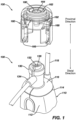
- Figure 1 illustrates an example sheath introducer assembly 100 including a secondary valve accessory device 160 and a sheath introducer 110.
- the secondary valve accessory device 160 is illustrated detached from the sheath introducer 110.
- the secondary valve accessory device 160 can be manufactured separately from the sheath introducer 110 and subsequently attached by a user (e.g., physician or other health care provider).
- the secondary valve accessory device 160 can include latch extensions 166 configured to snap onto a ridge 114 at a proximal end 116 of a handle 112 of the sheath introducer 110.
- the secondary valve accessory device 160 and the sheath introducer 110 can be assembled together by other suitable mechanical attachment mechanism (e.g., interference fit, screw threads, double sided tape, adhesive, etc.) as understood by a person skilled in the pertinent art.
- a secondary hemostatic valve assembly 162 similar to that of the illustrated secondary valve accessory device 160 can be integral to the sheath introducer 110.
- the sheath introducer 110 can be configured similarly to introducers known in the art.
- the sheath introducer 110 can be deflectable such as described in U.S. Patent 10,046,141 incorporated herein by reference and attached in the Appendix of priority application U.S. 63/272,722 , a CARTO VIZIGO ® Bi-Directional Guiding sheath by Biosense Webster, and/or a MOBICATH ® Sheath by Biosense Webster.
- the sheath introducer can be fixed similar to a CARDIAGUIDE TM Fixed Sheath by Biosense Webster.
- the sheath introducer 110 can have an identical structure to known sheath introducers, or a structure similar to known sheath introducers that is modified to include one or more mating features 114 such as, but not limited to, a ridge and/or threads to facilitate attachment.
- the sheath introducer 110 can include a primary hemostatic valve assembly 130 having a primary valve opening 132.
- the primary valve opening can be sized to receive an intralumenal device 150 (see Figure 2 ) to facilitate catheter based diagnostics and/or treatments (e.g., mapping, ablation, etc.).
- the sheath introducer 110 can include a side port 134 similar to some known sheath introducers.
- the sheath introducer 110 can include an electrical connector 118 similar to some known sheath introducers.
- the secondary valve accessory device 160 can include a secondary valve opening 164 that aligns to the primary valve opening 132 of the sheath introducer 110 when the secondary valve accessory device 160 is attached to the sheath introducer 110.
- the secondary valve accessory device 160 can include an inner housing 182 having a funnel shape that can function as an introducer tool for an intralumenal device.
- the secondary valve accessory device 160 can include an O-ring 168 around an outside surface of the inner housing 182 that is positioned to seal to a proximal end of the primary valve assembly 130 to create an intermediate chamber between the primary seal 136 and the secondary seal 180.
- FIG. 2 illustrates an example intralumenal device and secondary valve assembly 102 including an intralumenal device 150 and the secondary valve accessory device 160.
- the intralumenal device 150 can include a catheter shaft 152 and an end effector 154.
- the intralumenal device 150 can be configured similar to any number of known devices including catheters for diagnostics and/or treatments.
- the end effector 154 can have a diameter D2 that is larger than a diameter D1 of the catheter shaft 152.
- the end effector 154 can include spine(s), lasso(s), balloon(s), and other such structures.
- the end effector 154 may be collapsed for delivery through the primary valve opening 132 of the sheath introducer 110 and can be configured to expand upon exiting a distal end of the sheath introducer 110.
- the end effector 154 is shown extending distally from the secondary valve accessory device 160.
- the end effector 154 can be positioned within the inner housing 182 (see Figure 1 ) prior to attachment of the secondary valve accessory device 160 to the sheath introducer 110, and the inner housing 182 can function as an introducer tool that aids insertion of the end effector 154 through the primary valve opening 132 and into the sheath introducer 110.
- the intralumenal device and secondary valve assembly 102 can be pre-assembled for use by a user with the end effector 154 pre-loaded into the inner housing 182.
- the user may first attach the secondary valve accessory device 160 to the proximal end 116 of the sheath introducer 110, then push the catheter shaft 152 distally to move the end effector 154 distally from the inner housing 182 of the secondary valve accessory device 160, through the primary valve opening 132, and into an elongated shaft 120 of the sheath introducer (see Figures 3B and 3C ).
- the secondary valve opening 164 can be sized smaller than the primary valve opening 132 because the secondary valve opening 164 can be sized to receive the smaller diameter D1 of the catheter shaft 152 while the primary valve opening is sized to receive the larger diameter D2 of the end effector 154.
- the tighter seal of the secondary valve opening 164 around the catheter shaft 152 can therefore reduce risk of leak and air entrainment compared to a system in which all seal(s) must be sized to accommodate the larger diameter D2 of the end effector 154.
- the secondary valve accessory device 160 can further be configured to detach from the sheath introducer 110 so that subsequent intralumenal devices can be inserted into the sheath introducer 110.
- Figure 3A illustrates a side view of a proximal end of the example sheath introducer assembly 100 with the secondary accessory device 160 attached to the sheath introducer 110.
- the illustration shows the side port 134 rotated to the forefront.
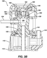
- Figure 3B illustrates a cross-sectional view of the example sheath introducer assembly in a plane perpendicular to the plane of the page as indicated in Figure 3A .
- Figure 3C illustrates a cross-sectional view of the example sheath introducer assembly in a plane parallel to the plane of the page as indicated in Figure 3A .
- the sheath introducer assembly 100 includes an intermediate chamber 140 between a secondary seal 180 of the secondary hemostatic valve assembly 162 and a primary seal 136 of the primary hemostatic valve assembly 130.
- the sheath introducer assembly 100 also includes a chamber 138 on the distal side of the primary seal 136 that leads distally to a lumen 122 of the elongated shaft 120 of the sheath introducer 110.
- the intermediate chamber 140 can be bound by the secondary seal 180, the primary seal 136, and the inner housing 182 of the secondary valve accessory device 160.
- the intermediate chamber 140 can be fluidically sealed, by the secondary seal 180 and the inner housing 182, from an external environment.
- the intermediate chamber 140 can be fluidically sealed, by the primary seal 136, from the chamber 138 on the distal side of the primary seal 136.
- the side port 134 is in fluidic communication with the chamber 138 on the distal side of the primary seal 136, and thereby the side port 134 is in fluidic communication with the lumen 122 of the elongated shaft 120.
- the sheath introducer assembly 100 can further include a secondary side port in fluidic communication with the intermediate chamber 140.
- the secondary side port can be configured similarly to the side port 134 of the sheath introducer 110 to allow aspiration of the intermediate chamber 140.
- the side port 134 of the sheath introducer 110 can be optional.
- the secondary side port can be integral to the secondary valve accessory device 160.
- Figure 4 illustrates an exploded view of the secondary valve accessory device 160 modified so that the secondary seal 180 is able to move in the direction of the longitudinal axis L-L ("longitudinally") in response to a pressure differential between the intermediate chamber and an external environment, wherein the secondary valve 180 is positioned between the intermediate chamber 140 and the external environment.
- Figures 3B and 3C illustrate a stationary secondary seal 180.
- the stationary secondary seal 180 is simpler to manufacture and may be sufficient to reduce leakage and/or entrainment in many treatment methods.
- the movable secondary seal 180 may provide additional pressure dampening in treatment methods which typically result in larger pressure differentials.
- the secondary valve accessory device 160 illustrated in Figures 4 through 6 can be used in place of the secondary valve accessory device 160 illustrated in Figures 3B and 3C .
- the secondary hemostatic valve assembly 162 can include a proximal retainer ring 172, one or more springs 174, a proximal washer 176, the secondary seal 180, a distal washer 178, and the inner housing 182.
- the inner housing 182 can include a seal chamber 184 and a tubular extension 186.
- the seal chamber 184 can have an inner diameter D.
- the tubular extension 186 can include a funnel taper at its proximal end that opens to the seal chamber 184. The funnel taper can be shaped to guide an intralumenal device toward the longitudinal axis L-L.
- the secondary valve accessory device 160 can include a housing 170 providing structural support for the secondary hemostatic valve assembly 162.
- the housing 170 can be configured to attach to the sheath introducer 110.
- the housing 170 can be integral to the sheath introducer 110.
- Figure 5 illustrates a cross-sectional view of the secondary hemostatic valve assembly 162 of Figure 4 in which the secondary seal 180 is in a first position.
- the secondary seal 180 is secured between the proximal washer 176 and the distal washer 178.
- the springs 174 extend between the proximal retainer ring 172 and the proximal washer 176 to press the distal washer 178 against a distal surface of the inner housing 182 within the seal chamber 184.
- the external environment is at an ambient pressure P0
- the intermediate chamber 140 is at an internal pressure P1.
- Figure 6 illustrates a cross-sectional view of the secondary hemostatic valve assembly 162 of Figure 4 in which the secondary seal 180 is in a second position.
- the intermediate chamber 140 is at an increased pressure P2 such that the pressure differential from the intermediate chamber to the external environment provides sufficient force to cause the springs 174 to compress to their fullest extent.
- the spring force can be tailored to cause the secondary seal 180 to move from the first position to the second position, and a contiguous range of positions therebetween, as a function of pressure differential between the intermediate chamber 140 and the external environment as understood by a person skilled in the pertinent art.
- the secondary seal 180 is translated a length L1 upon moving from the first position to the second position.
- the translation of the secondary seal 180 increases the internal volume of the intermediate chamber 140 by a volume that can be calculated as cross-sectional area of the seal chamber 184 times the translated length L1, where the change in internal volume can be equal to pi ⁇ (1/2 D) 2 ⁇ L1 for a cylindrical seal chamber 184.
- the increase in volume of the intermediate chamber 140 can be effective to decrease the pressure within the intermediate chamber, and thereby reduce risk of leakage through the secondary valve opening 164.
- the amount of pressure relieved is a function of increase in internal volume of the intermediate chamber 140 where the greater the change in volume, the greater the amount of pressure relieved.
- Pressure damping is therefore determined by spring force and change in internal volume of the intermediate chamber 140.
- the spring stiffness and/or change in internal volume can be designed to damp a specific pressure profile related to manipulating of a specific intralumenal device through a specific sheath. For instance, an intralumenal device having a large balloon end effector may result in higher pressure differentials compared to a an intralumenal device having a smaller end effector or an end effector with spines when delivered through the same sheath introducer, and the same intralumenal device delivered through a smaller sheath introducer may result in higher pressure differentials compared to the same intralumenal device delivered through a larger sheath.
- the spring force and volume can be increased for higher pressure differentials and decreased for lower pressure differentials.
- the chamber 138 on the distal side of the primary seal 136 can be at a third pressure.
- the third pressure can be the same or different from the pressure of the intermediate chamber 140.
- the primary valve opening 132 can be larger than a primary valve opening of a sheath introducer lacking the secondary hemostatic valve assembly 162 for comparable treatment methods because the secondary hemostatic valve can compensate for leakage and/or entrainment through the primary valve opening 132.
- a larger primary valve opening 132 may be desirable to accommodate a large end effector. Therefore, some fluidic exchange between the intermediate chamber 140 and the chamber 138 on the distal side of the primary seal 136 can be tolerated, which can result in reduced pressure differential between the intermediate chamber 140 and the chamber 138 on the distal side of the primary seal 136.
- Figure 7 illustrates the sheath introducer assembly 100 and intralumenal device 150 in use.
- a user 10 is manipulating the intralumenal device 150 which is inserted through the compound valve assembly of the sheath introducer assembly 100.
- the user 10 is in an external environment at a pressure P0.
- the compound valve can reduce likelihood of outward leaks due to accumulation of pressure within the sheath introducer 110 compared to operation of a similar system lacking the secondary hemostatic valve assembly 162.
- the compound valve can reduce likelihood of air entrainment when the end effector breaches the primary seal compared to operation of a similar system lacking the secondary hemostatic valve assembly 162.
- the compound valve can be effective to reduce leakage when pressure within the chamber 138 on the distal side of the primary seal 136 measures from about 10 to about 15 pounds per square inch (psi) when measured through the side port 134.
- Figure 8A illustrates another example secondary valve accessory device 260.
- Figure 8B illustrates a cross-sectional view of the secondary valve accessory device 260 as indicated in Figure 8A .
- the secondary valve accessory device 260 illustrated in Figures 8A and 8B can be configured similarly to the secondary valve accessory device 160 illustrated in Figures 1 through 6 .
- the secondary valve accessory device 260 illustrated in Figures 8A and 8B includes a housing 270 having threads 217 rather than latch extensions 166 as illustrated in Figures 1 through 3C .
- the secondary valve accessory device 260 illustrated in Figures 8A and 8B can therefore be screwed onto a sheath introducer configured similarly to the sheath introducer 110 illustrated in Figures 1 through 3C but for having screw threads in place of the ridge 114.
- the secondary valve accessory device 260 illustrated in Figures 8A and 8B includes a secondary hemostatic valve assembly 262 including a proximal retainer ring 272, an inner housing 282, and an O-ring 268.
- the secondary valve assembly 260 can further include a stationary secondary seal similar to as illustrated in Figures 3B , 3C or a movable secondary seal positioned within a seal chamber 284 of the inner housing 282 similar to as illustrated in Figures 4 , 5 , and 6 .
- the inner housing 282 can further include a tubular extension 286. The length of the tubular extension 286 can be sized to fit an end effector of predetermined size so that the secondary valve accessory device 260 can be integrated with an intralumenal device similar to the intralumenal device and secondary valve assembly 102 illustrated in Figure 2 .
- Figure 9 illustrates a cut-away view of an example sheath introducer assembly 200 including the secondary valve accessory 260 illustrated in Figures 8A and 8B and a sheath introducer 210 having a threaded proximal end and a side port 234.
- the sheath introducer assembly 200 can function and be configured similarly to the sheath introducer assembly 100 illustrated in Figures 1 through 7 and described elsewhere herein.
Landscapes
- Health & Medical Sciences (AREA)
- Heart & Thoracic Surgery (AREA)
- Life Sciences & Earth Sciences (AREA)
- Animal Behavior & Ethology (AREA)
- Public Health (AREA)
- Biomedical Technology (AREA)
- Hematology (AREA)
- Engineering & Computer Science (AREA)
- Pulmonology (AREA)
- General Health & Medical Sciences (AREA)
- Anesthesiology (AREA)
- Veterinary Medicine (AREA)
- Biophysics (AREA)
- Infusion, Injection, And Reservoir Apparatuses (AREA)
- Media Introduction/Drainage Providing Device (AREA)
- Materials For Medical Uses (AREA)
- Quick-Acting Or Multi-Walled Pipe Joints (AREA)
- Valve Housings (AREA)
Abstract
Description
- This application claims the benefit of priority to prior filed
U.S. Provisional Patent Application No. 63/272,722 filed on October 28, 2021 - The present invention relates to valves for catheter delivery, and in particular hemostasis valves for a sheath introducer.
- A "sheath" or "sheath introducer" includes a tube placed in an artery or vein of a patient during a medical procedure that, when positioned for treatment, has a distal end within the artery or vein and a proximal end outside of the patient. A hemostasis valve at the proximal end of the sheath inhibits blood from exiting the sheath and allows longer sheaths and/or catheters to be inserted through the sheath into the artery or vein.
- A problem with some current sheath introducers for catheter delivery is that movement of devices through the sheath can result in a pressure differential between an inner lumen of the sheath and the ambient environment which can potentially allow for air entrainment and/or leakage through the seal of the sheath.
- The present invention relates to valves for catheter delivery, and in particular hemostasis valves for a sheath introducer.
- An example catheter sheath assembly can include an elongated shaft, a primary hemostatic valve assembly, and a secondary hemostatic valve assembly. The elongated shaft can include a distal end, a proximal end, and a lumen extending along a longitudinal axis and providing a passageway into the proximal end of the shaft and out of the distal end of the shaft. The primary hemostatic valve assembly can fluidically seal to the proximal end of the elongated shaft and include a primary seal. The secondary hemostatic valve assembly can include a secondary seal disposed in a proximal direction in relation to the primary seal such that the primary hemostatic valve assembly and the secondary hemostatic valve assembly define an intermediate chamber disposed at least in part between the primary seal and the secondary seal.
- The secondary seal can be movable in relation to the primary seal to thereby change an internal volume of the intermediate chamber. The secondary seal can be configured to slide parallel to the longitudinal axis and within a housing portion of the secondary hemostatic valve assembly. The housing portion can be fixed in relation to the primary seal. The change in volume can be equal to an interior cross-sectional area of the intermediate chamber orthogonal to the longitudinal axis multiplied by a change in longitudinal position of the secondary seal. The secondary seal can be configured to move in response to a pressure differential between the intermediate chamber and an external environment. The internal volume of the intermediate chamber being configured to change in response to a difference in pressure between the intermediate chamber and an external environment.
- The secondary hemostatic valve assembly can further include one or more springs configured to change in length to thereby move the secondary valve opening in relation to the primary valve opening. The change in volume can be based at least in part on stiffness of the one or more springs. The one or more springs can be configured to compress to increase the volume of the intermediate chamber.
- The primary seal can include a primary valve opening aligned to the longitudinal axis. The secondary seal can include a secondary valve opening aligned to the longitudinal axis.
- The intermediate chamber can be fluidically sealed from an external environment by the secondary seal and can be sealed from the lumen of the elongated shaft by the primary seal.
- The intermediate chamber can be shaped by a tubular housing portion extending between the secondary seal and the primary seal.
- The catheter sheath assembly can further include a handle joining the elongated shaft to the primary hemostatic valve assembly. The handle can be configured to be manipulated to reshape the elongated shaft. The secondary hemostatic valve assembly can include latch extensions configured to slide over a proximal end of the handle and latch to the proximal end of the handle to thereby create the intermediate chamber. Alternatively, the secondary hemostatic valve assembly can be integral to the handle.
- The primary valve opening can be expandable to a larger diameter than the secondary valve opening.
- The catheter sheath assembly can further include an aspiration port in fluidic communication with the fluidically sealed chamber.
- The catheter sheath assembly can further include an interior housing including a funnel opening have a wide proximal end positioned in a distal direction from the secondary seal and a narrow distal end positioned in a proximal direction from the primary seal.
- The interior housing can be configured to urge an intralumenal device being inserted into the proximal end of the catheter sheath assembly toward the longitudinal axis and the primary valve opening.
- An example assembly can include a secondary valve accessory device and a catheter. The secondary valve accessory device can include a secondary seal, a tubular inner housing extending distally from the secondary seal, and an outer housing structurally supporting the secondary seal and the tubular inner housing. The catheter can include an elongated shaft and an end effector. The elongated shaft can define a longitudinal axis and extend through the secondary seal. The end effector can be positioned within the tubular inner housing.
- The outer housing can further include a mating feature configured to engage a proximal end of a sheath introducer. The mating feature can include a latch extension. Additionally, or alternatively, the mating feature can include threads.
- The tubular inner housing can include a distal end configured to seal to a proximal end of a primary hemostasis valve of a sheath introducer so that an intermediate chamber is bounded by the tubular inner housing, the secondary seal, and a primary seal of the primary hemostasis valve.
- The secondary valve accessory device can include an O-ring disposed around an outer surface of the tubular inner housing.
- The tubular inner housing can include a tapered portion having a wider diameter approximate the secondary seal and tapering to a narrow diameter distally from the secondary seal.
- The secondary seal can include a secondary valve opening sized to allow the elongated shaft of the catheter to slide longitudinally therethrough and sized to inhibit the end effector of the catheter to slide longitudinally therethrough.
- The secondary seal can be configured to translate proximally in relation to the tubular inner housing and outer housing in response to a force applied in a proximal direction to the secondary seal.
- The secondary valve accessory device can further include a spring providing a spring force between the secondary seal and the outer housing.
- The assembly can further include a sheath introducer including a primary hemostatic valve assembly. The primary hemostatic valve assembly can include a primary seal. The sheath introducer can be attached to the secondary valve accessory device such that the secondary seal is positioned in a distal direction in relation to the primary seal and an intermediate chamber is bounded at least in part by the secondary seal, the primary seal, and the tubular inner housing.
- An example method of treatment can include one or more of the following steps presented in no particular order. The example method can include additional steps as would be appreciated and understood by a person having pertinent skill in the art. The example method can be performed using an example assembly as disclosed herein, a variation thereof, or an alternative thereto as would be appreciated and understood by a person skilled in the pertinent art.
- An assembly comprising a secondary valve accessory device and a catheter can be selected such that an elongated shaft of the catheter extends through a secondary seal of the secondary valve accessory and an end effector of the catheter is positioned within a tubular inner housing of the secondary valve accessory.
- An outer housing of the secondary valve assembly can be attached to a proximal end of a sheath introducer such that the secondary valve is aligned with a primary valve of the sheath introducer and an intermediate chamber is bounded at least in part by the secondary seal, the primary seal, and the tubular inner housing
- The catheter shaft can be moved distally to thereby move the end effector of the catheter out of the tubular inner housing and through the primary seal.
- These and other aspects of the disclosed technology are described herein along with the accompanying figures. Other aspects, features, and elements of the disclosed technology will become apparent to those skilled in the pertinent art upon reviewing the following description of specific examples of the disclosed technology. While features of the disclosed technology may be discussed relative to certain examples and figures, the disclosed technology can include one or more of the features or elements discussed herein. Further, while one or more examples may be discussed as having certain advantageous features, one or more of such features may also be used with the various other examples of the disclosure discussed herein. In similar fashion, while certain examples, implementations, and embodiments may be discussed below with respect to a given device, system, or method, it is to be understood that such examples can be implemented in various other devices, systems, and methods of the present disclosure.
-
-
Figure 1 illustrates an example sheath introducer assembly with a secondary valve accessory device detached from a sheath introducer according to aspects of the present invention. -
Figure 2 illustrates an example catheter and secondary valve assembly including an intralumenal device and the secondary valve accessory device according to aspects of the present invention. -
Figure 3A illustrates a side view of a proximal end of the example sheath introducer assembly with the secondary accessory device attached to the sheath introducer according to aspects of the present invention. -
Figures 3B and3C illustrate cross-sectional views of the example sheath introducer assembly as indicated inFigure 3A according to aspects of the present invention. -
Figure 4 illustrates an exploded view of an example secondary valve accessory device according to aspects of the present invention. -
Figure 5 illustrates a cross-sectional view of a secondary hemostatic valve assembly of the secondary valve accessory device in which a seal of the secondary hemostatic valve assembly is in a first position according to aspects of the present invention. -
Figure 6 illustrates a cross-sectional view of the secondary hemostatic valve assembly in which the seal of the secondary hemostatic valve assembly is in a second position according to aspects of the present invention. -
Figure 7 illustrates a sheath introducer assembly in use according to aspects of the present invention. -
Figure 8A illustrates another example secondary valve accessory device according to aspects of the present invention. -
Figure 8B illustrates a cross-sectional view of the secondary valve accessory device as indicated inFigure 8A according to aspects of the present invention. -
Figure 9 illustrates a cut-away view of another example sheath introducer assembly including the secondary valve accessory device illustrated inFigures 8A and 8B according to aspects of the present invention. - As used herein, the terms "about" or "approximately" for any numerical values or ranges indicate a suitable dimensional tolerance that allows the part or collection of components to function for its intended purpose as described herein. More specifically, "about" or "approximately" may refer to the range of values ±20% of the recited value, e.g., "about 90%" may refer to the range of values from 71% to 99%.
- As used herein, the terms "comprising" or "containing" or "including" are interpreted to mean that at least the named compound, element, particle, or method step is present in the composition or article or method, but does not exclude the presence of other compounds, materials, particles, method steps, even if the other such compounds, material, particles, method steps have the same function as what is named.
- As used herein, the use of the term "external environment" is interpreted to mean an environment external to a medical device or assembly. When referring to the external environment of a medical device, assembly, or portion thereof that is external to a patient, the "external environment" is interpreted to be external to the patient. For instance, the "external environment" can include an environment in which a user interacts with the medical device/assembly.
- As used herein, the use of terms such as "having," "has," "including," or "includes" are open-ended and are intended to have the same meaning as terms such as "comprising" or "comprises" and not preclude the presence of other structure, material, or acts. Similarly, though the use of terms such as "can" or "may" are intended to be open-ended and to reflect that structure, material, or acts are not necessary, the failure to use such terms is not intended to reflect that structure, material, or acts are essential. To the extent that structure, material, or acts are presently considered to be essential, they are identified as such.
- As used herein, the terms "tubular" and "tube" are to be construed broadly and are not limited to a structure that is a right cylinder or strictly circumferential in cross-section or of a uniform cross-section throughout its length. For example, the tubular structure or system is generally illustrated as a substantially right cylindrical structure. However, the tubular system may have a tapered or curved outer surface without departing from the scope of the present invention.
- Ranges described as being between a first value and a second value are inclusive of the first and second values, as well as all values therebetween. Likewise, ranges described as being from a first value and to a second value are inclusive of the first and second values, as well as all values therebetween.
- It is also to be understood that the mention of one or more method steps does not preclude the presence of additional method steps or intervening method steps between those steps expressly identified.
- The components described hereinafter as making up various elements of the disclosure are intended to be illustrative and not restrictive. Many suitable components that would perform the same or similar functions as the components described herein are intended to be embraced within the scope of the disclosure. Such other components not described herein can include, but are not limited to, for example, similar components that are developed after development of the presently disclosed subject matter.
- In some examples presented herein, a secondary valve can be connected to the proximal end of a sheath introducer to work in conjunction with a primary valve of the sheath introducer, thereby resulting in a compound valve system. In some examples, the compound valve system can reduce air entrainment into the sheath introducer compared to a similar sheath introducer lacking the secondary valve because the secondary valve inhibits air from traveling through the compound valve system. Additionally, the compound valve system can be modified to dampen pressure buildups during catheter retraction by allowing internal volume expansion with pressure increase within the sheath introducer with compound valve.
- The compound valve system can be integral to the sheath introducer or integral to a secondary valve accessory device that can be attached to a proximal end of the sheath introducer.
- In some examples, the secondary valve can be designed to interface with a specific diameter of intralumenal device (e.g., specific catheter shaft diameter). In some such examples, the secondary valve opening can be sized large enough to allow a catheter shaft to pass therethrough but too small to allow a larger end effector to pass therethrough. In some such examples, the secondary valve can be integral to a secondary valve accessory device that can be built onto an end effector introducer tool so that the secondary valve accessory device is integral to the intralumenal device. Such examples can allow easy insertion of a large end effector of a catheter through a primary valve having a larger opening than the secondary valve opening. The smaller secondary valve opening can be effective to reduce risk of leak and air entrainment.
- In some examples, the compound valve system can include an aspiration port to reduce pressure between the primary and secondary valves. The aspiration port can be aspirated to remove bubbles to reduce risk of air entrainment. Aspiration can be used in addition to, or as a replacement for internal volume expansion in the compound valve system.
- Reference will now be made in detail to examples of the disclosed technology, such as those illustrated in the accompanying drawings. Wherever convenient, the same references numbers will be used throughout the drawings to refer to the same or like parts.
-
Figure 1 illustrates an example sheath introducerassembly 100 including a secondaryvalve accessory device 160 and asheath introducer 110. The secondaryvalve accessory device 160 is illustrated detached from thesheath introducer 110. The secondaryvalve accessory device 160 can be manufactured separately from thesheath introducer 110 and subsequently attached by a user (e.g., physician or other health care provider). As illustrated, the secondaryvalve accessory device 160 can includelatch extensions 166 configured to snap onto aridge 114 at aproximal end 116 of ahandle 112 of thesheath introducer 110. Additionally, or alternatively, the secondaryvalve accessory device 160 and thesheath introducer 110 can be assembled together by other suitable mechanical attachment mechanism (e.g., interference fit, screw threads, double sided tape, adhesive, etc.) as understood by a person skilled in the pertinent art. Alternatively, a secondaryhemostatic valve assembly 162 similar to that of the illustrated secondaryvalve accessory device 160 can be integral to thesheath introducer 110. - The
sheath introducer 110 can be configured similarly to introducers known in the art. Thesheath introducer 110 can be deflectable such as described inU.S. Patent 10,046,141 U.S. 63/272,722 sheath introducer 110 can have an identical structure to known sheath introducers, or a structure similar to known sheath introducers that is modified to include one or more mating features 114 such as, but not limited to, a ridge and/or threads to facilitate attachment. - The
sheath introducer 110 can include a primaryhemostatic valve assembly 130 having aprimary valve opening 132. The primary valve opening can be sized to receive an intralumenal device 150 (seeFigure 2 ) to facilitate catheter based diagnostics and/or treatments (e.g., mapping, ablation, etc.). Thesheath introducer 110 can include aside port 134 similar to some known sheath introducers. Thesheath introducer 110 can include anelectrical connector 118 similar to some known sheath introducers. - The secondary
valve accessory device 160 can include asecondary valve opening 164 that aligns to the primary valve opening 132 of thesheath introducer 110 when the secondaryvalve accessory device 160 is attached to thesheath introducer 110. The secondaryvalve accessory device 160 can include aninner housing 182 having a funnel shape that can function as an introducer tool for an intralumenal device. The secondaryvalve accessory device 160 can include an O-ring 168 around an outside surface of theinner housing 182 that is positioned to seal to a proximal end of theprimary valve assembly 130 to create an intermediate chamber between theprimary seal 136 and thesecondary seal 180. -
Figure 2 illustrates an example intralumenal device andsecondary valve assembly 102 including anintralumenal device 150 and the secondaryvalve accessory device 160. Theintralumenal device 150 can include acatheter shaft 152 and anend effector 154. Theintralumenal device 150 can be configured similar to any number of known devices including catheters for diagnostics and/or treatments. Theend effector 154 can have a diameter D2 that is larger than a diameter D1 of thecatheter shaft 152. For instance, theend effector 154 can include spine(s), lasso(s), balloon(s), and other such structures. Theend effector 154 may be collapsed for delivery through the primary valve opening 132 of thesheath introducer 110 and can be configured to expand upon exiting a distal end of thesheath introducer 110. - For the sake of illustration, the
end effector 154 is shown extending distally from the secondaryvalve accessory device 160. In practice, theend effector 154 can be positioned within the inner housing 182 (seeFigure 1 ) prior to attachment of the secondaryvalve accessory device 160 to thesheath introducer 110, and theinner housing 182 can function as an introducer tool that aids insertion of theend effector 154 through theprimary valve opening 132 and into thesheath introducer 110. The intralumenal device andsecondary valve assembly 102 can be pre-assembled for use by a user with theend effector 154 pre-loaded into theinner housing 182. To use the intralumenal device andsecondary valve assembly 102 with thesheath introducer 110, the user may first attach the secondaryvalve accessory device 160 to theproximal end 116 of thesheath introducer 110, then push thecatheter shaft 152 distally to move theend effector 154 distally from theinner housing 182 of the secondaryvalve accessory device 160, through theprimary valve opening 132, and into anelongated shaft 120 of the sheath introducer (seeFigures 3B and3C ). - When the intralumenal device and
secondary valve assembly 102 is configured as such, thesecondary valve opening 164 can be sized smaller than theprimary valve opening 132 because thesecondary valve opening 164 can be sized to receive the smaller diameter D1 of thecatheter shaft 152 while the primary valve opening is sized to receive the larger diameter D2 of theend effector 154. The tighter seal of thesecondary valve opening 164 around thecatheter shaft 152 can therefore reduce risk of leak and air entrainment compared to a system in which all seal(s) must be sized to accommodate the larger diameter D2 of theend effector 154. - The secondary
valve accessory device 160 can further be configured to detach from thesheath introducer 110 so that subsequent intralumenal devices can be inserted into thesheath introducer 110. -
Figure 3A illustrates a side view of a proximal end of the example sheath introducerassembly 100 with thesecondary accessory device 160 attached to thesheath introducer 110. The illustration shows theside port 134 rotated to the forefront. -
Figure 3B illustrates a cross-sectional view of the example sheath introducer assembly in a plane perpendicular to the plane of the page as indicated inFigure 3A . -
Figure 3C illustrates a cross-sectional view of the example sheath introducer assembly in a plane parallel to the plane of the page as indicated inFigure 3A . - Referring collectively to
Figures 3B and3C , thesheath introducer assembly 100 includes anintermediate chamber 140 between asecondary seal 180 of the secondaryhemostatic valve assembly 162 and aprimary seal 136 of the primaryhemostatic valve assembly 130. Thesheath introducer assembly 100 also includes achamber 138 on the distal side of theprimary seal 136 that leads distally to alumen 122 of theelongated shaft 120 of thesheath introducer 110. Theintermediate chamber 140 can be bound by thesecondary seal 180, theprimary seal 136, and theinner housing 182 of the secondaryvalve accessory device 160. Theintermediate chamber 140 can be fluidically sealed, by thesecondary seal 180 and theinner housing 182, from an external environment. Theintermediate chamber 140 can be fluidically sealed, by theprimary seal 136, from thechamber 138 on the distal side of theprimary seal 136. - As illustrated in
Figure 3B , theside port 134 is in fluidic communication with thechamber 138 on the distal side of theprimary seal 136, and thereby theside port 134 is in fluidic communication with thelumen 122 of theelongated shaft 120. Although not illustrated, thesheath introducer assembly 100 can further include a secondary side port in fluidic communication with theintermediate chamber 140. The secondary side port can be configured similarly to theside port 134 of thesheath introducer 110 to allow aspiration of theintermediate chamber 140. In some examples including the secondary side port, theside port 134 of thesheath introducer 110 can be optional. The secondary side port can be integral to the secondaryvalve accessory device 160. -
Figure 4 illustrates an exploded view of the secondaryvalve accessory device 160 modified so that thesecondary seal 180 is able to move in the direction of the longitudinal axis L-L ("longitudinally") in response to a pressure differential between the intermediate chamber and an external environment, wherein thesecondary valve 180 is positioned between theintermediate chamber 140 and the external environment.Figures 3B and3C illustrate a stationarysecondary seal 180. The stationarysecondary seal 180 is simpler to manufacture and may be sufficient to reduce leakage and/or entrainment in many treatment methods. The movablesecondary seal 180 may provide additional pressure dampening in treatment methods which typically result in larger pressure differentials. The secondaryvalve accessory device 160 illustrated inFigures 4 through 6 can be used in place of the secondaryvalve accessory device 160 illustrated inFigures 3B and3C . - Referring to
Figure 4 , the secondaryhemostatic valve assembly 162 can include aproximal retainer ring 172, one ormore springs 174, aproximal washer 176, thesecondary seal 180, adistal washer 178, and theinner housing 182. Theinner housing 182 can include aseal chamber 184 and atubular extension 186. Theseal chamber 184 can have an inner diameter D. Thetubular extension 186 can include a funnel taper at its proximal end that opens to theseal chamber 184. The funnel taper can be shaped to guide an intralumenal device toward the longitudinal axis L-L. - The secondary
valve accessory device 160 can include ahousing 170 providing structural support for the secondaryhemostatic valve assembly 162. As in the previous illustrations, thehousing 170 can be configured to attach to thesheath introducer 110. Alternatively, thehousing 170 can be integral to thesheath introducer 110. -
Figure 5 illustrates a cross-sectional view of the secondaryhemostatic valve assembly 162 ofFigure 4 in which thesecondary seal 180 is in a first position. Thesecondary seal 180 is secured between theproximal washer 176 and thedistal washer 178. Thesprings 174 extend between theproximal retainer ring 172 and theproximal washer 176 to press thedistal washer 178 against a distal surface of theinner housing 182 within theseal chamber 184. The external environment is at an ambient pressure P0, and theintermediate chamber 140 is at an internal pressure P1. When thesecondary seal 180 is in the first position, the pressure differential from the intermediate chamber to the external environment does not provide sufficient force on thesecondary seal 180 to cause thesprings 174 to compress. -
Figure 6 illustrates a cross-sectional view of the secondaryhemostatic valve assembly 162 ofFigure 4 in which thesecondary seal 180 is in a second position. Theintermediate chamber 140 is at an increased pressure P2 such that the pressure differential from the intermediate chamber to the external environment provides sufficient force to cause thesprings 174 to compress to their fullest extent. The spring force can be tailored to cause thesecondary seal 180 to move from the first position to the second position, and a contiguous range of positions therebetween, as a function of pressure differential between theintermediate chamber 140 and the external environment as understood by a person skilled in the pertinent art. - The
secondary seal 180 is translated a length L1 upon moving from the first position to the second position. The translation of thesecondary seal 180 increases the internal volume of theintermediate chamber 140 by a volume that can be calculated as cross-sectional area of theseal chamber 184 times the translated length L1, where the change in internal volume can be equal to pi × (1/2 D)2 × L1 for acylindrical seal chamber 184. The increase in volume of theintermediate chamber 140 can be effective to decrease the pressure within the intermediate chamber, and thereby reduce risk of leakage through thesecondary valve opening 164. The amount of pressure relieved is a function of increase in internal volume of theintermediate chamber 140 where the greater the change in volume, the greater the amount of pressure relieved. - Pressure damping is therefore determined by spring force and change in internal volume of the
intermediate chamber 140. The spring stiffness and/or change in internal volume can be designed to damp a specific pressure profile related to manipulating of a specific intralumenal device through a specific sheath. For instance, an intralumenal device having a large balloon end effector may result in higher pressure differentials compared to a an intralumenal device having a smaller end effector or an end effector with spines when delivered through the same sheath introducer, and the same intralumenal device delivered through a smaller sheath introducer may result in higher pressure differentials compared to the same intralumenal device delivered through a larger sheath. The spring force and volume can be increased for higher pressure differentials and decreased for lower pressure differentials. - The
chamber 138 on the distal side of the primary seal 136 (seeFigures 3B and3C ) can be at a third pressure. The third pressure can be the same or different from the pressure of theintermediate chamber 140. In some examples, theprimary valve opening 132 can be larger than a primary valve opening of a sheath introducer lacking the secondaryhemostatic valve assembly 162 for comparable treatment methods because the secondary hemostatic valve can compensate for leakage and/or entrainment through theprimary valve opening 132. In some examples, a largerprimary valve opening 132 may be desirable to accommodate a large end effector. Therefore, some fluidic exchange between theintermediate chamber 140 and thechamber 138 on the distal side of theprimary seal 136 can be tolerated, which can result in reduced pressure differential between theintermediate chamber 140 and thechamber 138 on the distal side of theprimary seal 136. -
Figure 7 illustrates thesheath introducer assembly 100 andintralumenal device 150 in use. A user 10 is manipulating theintralumenal device 150 which is inserted through the compound valve assembly of thesheath introducer assembly 100. The user 10 is in an external environment at a pressure P0. When retracting theintralumenal device 150 from thesheath introducer assembly 100, the compound valve can reduce likelihood of outward leaks due to accumulation of pressure within thesheath introducer 110 compared to operation of a similar system lacking the secondaryhemostatic valve assembly 162. In some treatments in which the intralumenal device has a large or uniquely shaped end effector, the compound valve can reduce likelihood of air entrainment when the end effector breaches the primary seal compared to operation of a similar system lacking the secondaryhemostatic valve assembly 162. In some treatments, the compound valve can be effective to reduce leakage when pressure within thechamber 138 on the distal side of theprimary seal 136 measures from about 10 to about 15 pounds per square inch (psi) when measured through theside port 134. -
Figure 8A illustrates another example secondaryvalve accessory device 260. -
Figure 8B illustrates a cross-sectional view of the secondaryvalve accessory device 260 as indicated inFigure 8A . The secondaryvalve accessory device 260 illustrated inFigures 8A and 8B can be configured similarly to the secondaryvalve accessory device 160 illustrated inFigures 1 through 6 . The secondaryvalve accessory device 260 illustrated inFigures 8A and 8B includes a housing 270 havingthreads 217 rather than latchextensions 166 as illustrated inFigures 1 through 3C . The secondaryvalve accessory device 260 illustrated inFigures 8A and 8B can therefore be screwed onto a sheath introducer configured similarly to thesheath introducer 110 illustrated inFigures 1 through 3C but for having screw threads in place of theridge 114. - The secondary
valve accessory device 260 illustrated inFigures 8A and 8B includes a secondaryhemostatic valve assembly 262 including aproximal retainer ring 272, aninner housing 282, and an O-ring 268. Thesecondary valve assembly 260 can further include a stationary secondary seal similar to as illustrated inFigures 3B ,3C or a movable secondary seal positioned within aseal chamber 284 of theinner housing 282 similar to as illustrated inFigures 4 ,5 , and6 . Theinner housing 282 can further include atubular extension 286. The length of thetubular extension 286 can be sized to fit an end effector of predetermined size so that the secondaryvalve accessory device 260 can be integrated with an intralumenal device similar to the intralumenal device andsecondary valve assembly 102 illustrated inFigure 2 . -
Figure 9 illustrates a cut-away view of an example sheath introducerassembly 200 including thesecondary valve accessory 260 illustrated inFigures 8A and 8B and asheath introducer 210 having a threaded proximal end and aside port 234. Thesheath introducer assembly 200 can function and be configured similarly to thesheath introducer assembly 100 illustrated inFigures 1 through 7 and described elsewhere herein. - The descriptions contained herein are examples of embodiments of the invention and are not intended in any way to limit the scope of the invention. As described herein, the invention contemplates many variations and modifications of system components, including alternative combinations of components illustrated in separate figures, alternative materials, alternative component geometries, and alternative component placement. Modifications and variations apparent to those having skilled in the pertinent art according to the teachings of this disclosure are intended to be within the scope of the claims which follow.
Claims (20)
- A catheter sheath assembly, comprising:an elongated shaft comprising a distal end, a proximal end, and a lumen extending along a longitudinal axis and providing a passageway into the proximal end of the shaft and out of the distal end of the shaft;a primary hemostatic valve assembly fluidically sealing to the proximal end of the elongated shaft and comprising a primary seal; anda secondary hemostatic valve assembly comprising a secondary seal disposed in a proximal direction in relation to the primary seal such that the primary hemostatic valve assembly and the secondary hemostatic valve assembly define an intermediate chamber disposed at least in part between the primary seal and the secondary seal.
- The catheter sheath assembly of claim 1, the secondary seal being movable in relation to the primary seal to thereby change an internal volume of the intermediate chamber.
- The catheter sheath assembly of claim 2, the secondary seal being configured to slide parallel to the longitudinal axis and within a housing portion of the secondary hemostatic valve assembly, the housing portion being fixed in relation to the primary seal.
- The catheter sheath assembly of claim 3, the change in volume being equal to an interior cross-sectional area of the intermediate chamber orthogonal to the longitudinal axis multiplied by a change in longitudinal position of the secondary seal.
- The catheter sheath assembly of claim 2, the secondary seal being configured to move in response to a pressure differential between the intermediate chamber and an external environment.
- The catheter sheath assembly claim 2, the internal volume of the intermediate chamber being configured to change in response to a difference in pressure between the intermediate chamber and an external environment.
- The catheter sheath assembly of claim 2,the secondary hemostatic valve assembly further comprising one or more springs configured to change in length to thereby move the secondary valve opening in relation to the primary valve opening, andthe change in volume being based at least in part on stiffness of the one or more springs.
- The catheter sheath assembly of claim 7, the one or more springs being configured to compress to increase the volume of the intermediate chamber.
- The catheter sheath assembly of claim 1, the primary seal comprising a primary valve opening aligned to the longitudinal axis, and the secondary seal comprising a secondary valve opening aligned to the longitudinal axis.
- The catheter sheath assembly of claim 1, the intermediate chamber being fluidically sealed from an external environment by the secondary seal and being sealed from the lumen of the elongated shaft by the primary seal.
- The catheter sheath assembly of claim 1, the intermediate chamber being shaped by a tubular housing portion extending between the secondary seal and the primary seal.
- The catheter sheath assembly of claim 1, further comprising:
a handle joining the elongated shaft to the primary hemostatic valve assembly and configured to be manipulated to reshape the elongated shaft, the secondary hemostatic valve assembly being integral to the handle. - The catheter sheath assembly of claim 1, the primary valve opening being expandable to a larger diameter than the secondary valve opening.
- The catheter sheath assembly of claim 1, further comprising:
an aspiration port in fluidic communication with the intermediate chamber. - The catheter sheath assembly of claim 1, further comprising:
an interior housing comprising a funnel opening have a wide proximal end positioned in a distal direction from the secondary seal and a narrow distal end positioned in a proximal direction from the primary seal. - An assembly comprising:a secondary valve accessory device comprising a secondary seal, a tubular inner housing extending distally from the secondary seal, and an outer housing structurally supporting the secondary seal and the tubular inner housing; anda catheter comprising an elongated shaft and an end effector, the elongated shaft defining a longitudinal axis and extending through the secondary seal, the end effector being positioned within the tubular inner housing.
- The assembly of claim 16, the outer housing further comprising a mating feature configured to engage a proximal end of a sheath introducer.
- The assembly of claim 17, the mating feature comprising a latch extension.
- The assembly of claim 17, the mating feature comprising threads.
- The assembly of any claim 16, the tubular inner housing comprising a distal end configured to seal to a proximal end of a primary hemostasis valve of a sheath introducer so that an intermediate chamber is bounded by the tubular inner housing, the secondary seal, and a primary seal of the primary hemostasis valve.
Applications Claiming Priority (2)
| Application Number | Priority Date | Filing Date | Title |
|---|---|---|---|
| US202163272722P | 2021-10-28 | 2021-10-28 | |
| US17/957,453 US20230137558A1 (en) | 2021-10-28 | 2022-09-30 | Compound valve system for intracardiac tools |
Publications (1)
| Publication Number | Publication Date |
|---|---|
| EP4173668A1 true EP4173668A1 (en) | 2023-05-03 |
Family
ID=84043881
Family Applications (1)
| Application Number | Title | Priority Date | Filing Date |
|---|---|---|---|
| EP22203991.9A Pending EP4173668A1 (en) | 2021-10-28 | 2022-10-27 | Compound valve system for intracardiac tools |
Country Status (5)
| Country | Link |
|---|---|
| US (1) | US20230137558A1 (en) |
| EP (1) | EP4173668A1 (en) |
| JP (1) | JP2023066412A (en) |
| CN (1) | CN116036462A (en) |
| IL (1) | IL297559A (en) |
Citations (4)
| Publication number | Priority date | Publication date | Assignee | Title |
|---|---|---|---|---|
| US5324271A (en) * | 1993-06-04 | 1994-06-28 | Cordis Corporation | Double seal hemostasis connector |
| WO2001070308A1 (en) * | 2000-03-20 | 2001-09-27 | Arteria Medical Science, Inc. | Catheter introducer assembly with dual hemostatic valve |
| US10046141B2 (en) | 2008-12-30 | 2018-08-14 | Biosense Webster, Inc. | Deflectable sheath introducer |
| US20190076640A1 (en) * | 2017-09-12 | 2019-03-14 | Boston Scientific Limited | Hemostasis Valves and Methods for Making and Using Hemostasis Valves |
Family Cites Families (7)
| Publication number | Priority date | Publication date | Assignee | Title |
|---|---|---|---|---|
| US4331147A (en) * | 1980-07-01 | 1982-05-25 | Glasrock Products, Inc. | System for draining wounds |
| US5180365A (en) * | 1990-03-01 | 1993-01-19 | Ensminger William D | Implantable infusion device |
| US5197955A (en) * | 1991-10-18 | 1993-03-30 | Ethicon, Inc. | Universal seal for trocar assembly |
| US5492304A (en) * | 1993-06-16 | 1996-02-20 | United States Surgical Corporation | Seal assembly for accommodating introduction of surgical instruments |
| US5657963A (en) * | 1993-06-16 | 1997-08-19 | United States Surgical Corporation | Seal assembly for accommodating introduction of surgical instruments |
| US8628056B2 (en) * | 2009-02-02 | 2014-01-14 | Aptargroup, Inc. | Dual sealing system for use with a probe |
| US8932259B2 (en) * | 2010-09-13 | 2015-01-13 | Becton, Dickinson And Company | Catheter assembly |
-
2022
- 2022-09-30 US US17/957,453 patent/US20230137558A1/en active Pending
- 2022-10-23 IL IL297559A patent/IL297559A/en unknown
- 2022-10-27 JP JP2022172270A patent/JP2023066412A/en active Pending
- 2022-10-27 EP EP22203991.9A patent/EP4173668A1/en active Pending
- 2022-10-28 CN CN202211333267.3A patent/CN116036462A/en active Pending
Patent Citations (4)
| Publication number | Priority date | Publication date | Assignee | Title |
|---|---|---|---|---|
| US5324271A (en) * | 1993-06-04 | 1994-06-28 | Cordis Corporation | Double seal hemostasis connector |
| WO2001070308A1 (en) * | 2000-03-20 | 2001-09-27 | Arteria Medical Science, Inc. | Catheter introducer assembly with dual hemostatic valve |
| US10046141B2 (en) | 2008-12-30 | 2018-08-14 | Biosense Webster, Inc. | Deflectable sheath introducer |
| US20190076640A1 (en) * | 2017-09-12 | 2019-03-14 | Boston Scientific Limited | Hemostasis Valves and Methods for Making and Using Hemostasis Valves |
Also Published As
| Publication number | Publication date |
|---|---|
| CN116036462A (en) | 2023-05-02 |
| US20230137558A1 (en) | 2023-05-04 |
| IL297559A (en) | 2023-05-01 |
| JP2023066412A (en) | 2023-05-15 |
Similar Documents
| Publication | Publication Date | Title |
|---|---|---|
| US8535272B2 (en) | Sealing member for a catheter | |
| EP2117633B1 (en) | System with catheter system and an adaptor comprising a friction reducing sleeve | |
| US5320613A (en) | Medical lumen flushing and guide wire loading device and method | |
| EP2521578B1 (en) | Center twist hemostatic valve | |
| US5785689A (en) | Endoscopic catheter sheath position control | |
| US5209741A (en) | Surgical access device having variable post-insertion cross-sectional geometry | |
| EP2452640B1 (en) | Adapter for an introducer | |
| JP2020508153A (en) | Loading device for use with medical devices | |
| EP2594212A2 (en) | Tip deflecting puncture needle | |
| US20040172008A1 (en) | Hemostasis valve and method of using a hemostasis valve | |
| JP2009034522A (en) | Ureteral access sheath | |
| JP7440513B2 (en) | Retractable backflush fixture | |
| US11660113B2 (en) | Multi-diameter cannula | |
| WO2021183436A1 (en) | Arterial access needle with proximal port | |
| US10219928B2 (en) | Delivery catheter including collapsible sleeve and method of operating same | |
| US20230137558A1 (en) | Compound valve system for intracardiac tools | |
| US9078981B2 (en) | Catheter system including an embolism protection device | |
| US11724066B2 (en) | Strain relief and methods of use thereof | |
| EP3795198B1 (en) | Mechanism for manipulating a puller wire | |
| CN211461708U (en) | Flow choking catheter | |
| EP4154937A1 (en) | Floating hemostasis valve | |
| WO2009130457A1 (en) | Expanding medical collet | |
| US20230016752A1 (en) | Gasket with external sealing features for introducer sheath | |
| US9211390B2 (en) | Multi-functional wire guide assembly and method of using same | |
| CN120860435A (en) | Interventional telescopic catheter for cerebrovascular operation |
Legal Events
| Date | Code | Title | Description |
|---|---|---|---|
| PUAI | Public reference made under article 153(3) epc to a published international application that has entered the european phase |
Free format text: ORIGINAL CODE: 0009012 |
|
| STAA | Information on the status of an ep patent application or granted ep patent |
Free format text: STATUS: THE APPLICATION HAS BEEN PUBLISHED |
|
| AK | Designated contracting states |
Kind code of ref document: A1 Designated state(s): AL AT BE BG CH CY CZ DE DK EE ES FI FR GB GR HR HU IE IS IT LI LT LU LV MC ME MK MT NL NO PL PT RO RS SE SI SK SM TR |
|
| STAA | Information on the status of an ep patent application or granted ep patent |
Free format text: STATUS: REQUEST FOR EXAMINATION WAS MADE |
|
| 17P | Request for examination filed |
Effective date: 20231101 |
|
| RBV | Designated contracting states (corrected) |
Designated state(s): AL AT BE BG CH CY CZ DE DK EE ES FI FR GB GR HR HU IE IS IT LI LT LU LV MC ME MK MT NL NO PL PT RO RS SE SI SK SM TR |
|
| STAA | Information on the status of an ep patent application or granted ep patent |
Free format text: STATUS: EXAMINATION IS IN PROGRESS |
|
| 17Q | First examination report despatched |
Effective date: 20250723 |