EP4172848B1 - System and methods to optimize neural networks using sensor fusion - Google Patents
System and methods to optimize neural networks using sensor fusion Download PDFInfo
- Publication number
- EP4172848B1 EP4172848B1 EP21732924.2A EP21732924A EP4172848B1 EP 4172848 B1 EP4172848 B1 EP 4172848B1 EP 21732924 A EP21732924 A EP 21732924A EP 4172848 B1 EP4172848 B1 EP 4172848B1
- Authority
- EP
- European Patent Office
- Prior art keywords
- interest
- neural network
- sample set
- view
- field
- Prior art date
- Legal status (The legal status is an assumption and is not a legal conclusion. Google has not performed a legal analysis and makes no representation as to the accuracy of the status listed.)
- Active
Links
Images


Classifications
-
- G—PHYSICS
- G06—COMPUTING OR CALCULATING; COUNTING
- G06V—IMAGE OR VIDEO RECOGNITION OR UNDERSTANDING
- G06V10/00—Arrangements for image or video recognition or understanding
- G06V10/70—Arrangements for image or video recognition or understanding using pattern recognition or machine learning
- G06V10/77—Processing image or video features in feature spaces; using data integration or data reduction, e.g. principal component analysis [PCA] or independent component analysis [ICA] or self-organising maps [SOM]; Blind source separation
- G06V10/80—Fusion, i.e. combining data from various sources at the sensor level, preprocessing level, feature extraction level or classification level
- G06V10/803—Fusion, i.e. combining data from various sources at the sensor level, preprocessing level, feature extraction level or classification level of input or preprocessed data
-
- G—PHYSICS
- G06—COMPUTING OR CALCULATING; COUNTING
- G06V—IMAGE OR VIDEO RECOGNITION OR UNDERSTANDING
- G06V20/00—Scenes; Scene-specific elements
- G06V20/50—Context or environment of the image
- G06V20/52—Surveillance or monitoring of activities, e.g. for recognising suspicious objects
-
- G—PHYSICS
- G06—COMPUTING OR CALCULATING; COUNTING
- G06F—ELECTRIC DIGITAL DATA PROCESSING
- G06F18/00—Pattern recognition
- G06F18/20—Analysing
- G06F18/24—Classification techniques
- G06F18/241—Classification techniques relating to the classification model, e.g. parametric or non-parametric approaches
- G06F18/2413—Classification techniques relating to the classification model, e.g. parametric or non-parametric approaches based on distances to training or reference patterns
- G06F18/24133—Distances to prototypes
- G06F18/24143—Distances to neighbourhood prototypes, e.g. restricted Coulomb energy networks [RCEN]
-
- G—PHYSICS
- G06—COMPUTING OR CALCULATING; COUNTING
- G06F—ELECTRIC DIGITAL DATA PROCESSING
- G06F18/00—Pattern recognition
- G06F18/20—Analysing
- G06F18/25—Fusion techniques
-
- G—PHYSICS
- G06—COMPUTING OR CALCULATING; COUNTING
- G06V—IMAGE OR VIDEO RECOGNITION OR UNDERSTANDING
- G06V10/00—Arrangements for image or video recognition or understanding
- G06V10/10—Image acquisition
- G06V10/12—Details of acquisition arrangements; Constructional details thereof
- G06V10/14—Optical characteristics of the device performing the acquisition or on the illumination arrangements
- G06V10/143—Sensing or illuminating at different wavelengths
-
- G—PHYSICS
- G06—COMPUTING OR CALCULATING; COUNTING
- G06V—IMAGE OR VIDEO RECOGNITION OR UNDERSTANDING
- G06V10/00—Arrangements for image or video recognition or understanding
- G06V10/20—Image preprocessing
- G06V10/25—Determination of region of interest [ROI] or a volume of interest [VOI]
-
- G—PHYSICS
- G06—COMPUTING OR CALCULATING; COUNTING
- G06V—IMAGE OR VIDEO RECOGNITION OR UNDERSTANDING
- G06V10/00—Arrangements for image or video recognition or understanding
- G06V10/20—Image preprocessing
- G06V10/26—Segmentation of patterns in the image field; Cutting or merging of image elements to establish the pattern region, e.g. clustering-based techniques; Detection of occlusion
-
- G—PHYSICS
- G06—COMPUTING OR CALCULATING; COUNTING
- G06V—IMAGE OR VIDEO RECOGNITION OR UNDERSTANDING
- G06V10/00—Arrangements for image or video recognition or understanding
- G06V10/40—Extraction of image or video features
- G06V10/44—Local feature extraction by analysis of parts of the pattern, e.g. by detecting edges, contours, loops, corners, strokes or intersections; Connectivity analysis, e.g. of connected components
- G06V10/443—Local feature extraction by analysis of parts of the pattern, e.g. by detecting edges, contours, loops, corners, strokes or intersections; Connectivity analysis, e.g. of connected components by matching or filtering
- G06V10/449—Biologically inspired filters, e.g. difference of Gaussians [DoG] or Gabor filters
- G06V10/451—Biologically inspired filters, e.g. difference of Gaussians [DoG] or Gabor filters with interaction between the filter responses, e.g. cortical complex cells
- G06V10/454—Integrating the filters into a hierarchical structure, e.g. convolutional neural networks [CNN]
-
- G—PHYSICS
- G06—COMPUTING OR CALCULATING; COUNTING
- G06V—IMAGE OR VIDEO RECOGNITION OR UNDERSTANDING
- G06V10/00—Arrangements for image or video recognition or understanding
- G06V10/70—Arrangements for image or video recognition or understanding using pattern recognition or machine learning
- G06V10/82—Arrangements for image or video recognition or understanding using pattern recognition or machine learning using neural networks
Definitions
- the present disclosure is directed generally to optimizing neural networks through fusion of data captured by sensors of different modes.
- Deep learning neural networks typically include multiple intermediate layers of nodes resulting in large and complicated receptive fields and activation maps.
- the majority of the data in these receptive fields and activation maps will be unnecessary for the goal of the network.
- a thermal image analyzed by a neural network trained for activity detection may only contain relevant information in its upper-right quadrant.
- the processing of the receptive fields corresponding to the other three quadrants results in wasted computing time and energy. Accordingly, there is a need for (1) identifying relevant portions of the receptive field and (2) focusing on the relevant portions.
- US 2016/003493A1 discloses a passive infrared (PIR) motion sensor system which includes a non-contact thermopile detector for capturing infrared energy from a focused upon area in a room or zone deemed most likely to be occupied and generating a thermopile temperature signal therefrom, a pyroelectric detector for viewing through multiple passive lens elements (lenslets) that form PIR beams from a large portion of the room or zone and generating a pyroelectric signal therefrom, an ambient temperature sensor for sensing an ambient temperature in the room or zone and generating an ambient temperature signal detection threshold that is utilized in PIR detection therefrom and a microcomputer configured to process the thermopile temperature signal, the pyroelectric signal and the ambient temperature signal and determine whether the room or zone is occupied or unoccupied.
- PIR passive infrared
- Connected lighting systems include sensor bundles to capture samples used to control their associated luminaires.
- the sensor bundles may include different types of sensors, such as thermopile sensors and passive infrared (PIR) sensors.
- the connected lighting system may implement a neural network to process the samples collected by one of the sensor modes to control its associated luminaire. For example, the neural network may detect activity in a defined space by processing the data collected by the thermopile sensors.
- the present invention is a method of optimizing a neural network according to claim 1 and a system for optimizing a neural network according to claim 9.
- the present disclosure is directed generally to optimizing a neural network through fusion of data captured by sensors of different modes.
- the system utilizes two modalities of sensors of varying granularity, such as a first group of thermopiles and a second group of passive infrared (PIR) sensors.
- the system locates one or more regions of interest in the data captured by the second group, and translates this data from the sensor domain of the second group to the sensor domain of the first.
- the system then creates a binary matrix corresponding to the translated data.
- the binary matrix is loaded into the neural network to identify the nodes of the network which correspond to the translated regions of interest. Accordingly, these identified nodes also correspond to the relevant receptive fields of the thermopile data to be processed by the network.
- the system may then optimize the neural network by increasing or decreasing weight values of the nodes of the network based on relevance.
- the data captured by the first group of sensors may be processed in a more efficient manner by focusing on the most relevant receptive fields of the data captured by the first group of thermopiles.
- the neural network 202 may be a convolutional neural network.
- the neural network 202 may include a plurality of layers. Each layer may include a plurality of nodes 224. Each node 224 may have a weight value 230.
- the neural network 202 may be utilized for activity detection in a detection area, such as an office space. Additionally, other use cases for neural networks 202 are known, such as occupancy detection, people counting, and facial detection. Variations of the present systems and methods can generally be used in almost any object detection application with two sources of imagery. For example, in a people counting application, a system may use thermopile samples to identify regions of interest in a neural network for processing RGB (Red-Green-Blue) images.
- RGB Red-Green-Blue
- the neural network 202 is configured to process samples collected by one or more sensors monitoring the detection area. These sensors may be embedded in luminaires arranged in a connected lighting system in the office space.
- the system 200 may include a controller 204, a first sensor group 206, and a second sensor group 208 capable of communication via wired and/or wireless network 500.
- the controller 204 may include a memory 300, a processor 400, and a transceiver 510.
- the memory 300 and processor 400 may be communicatively coupled via a bus to facilitate processing of data stored in memory 300.
- Transceiver 510 may be used to receive samples from the first 206 and second 208 sensor group via the network 500.
- the data received by the transceiver 510 may be stored in memory 300 and/or processed by processor 400.
- the transceiver 510 may facilitate a wireless connection between the controller 204 and the network 500.
- the network 500 may be configured to facilitate communication between the controller 204, the first sensor group 206, the second sensor group 208, and/or any combination thereof.
- the network 400 may be a wired and/or wireless network following communication protocols such as Bluetooth, Wi-Fi, Zigbee, and/or other appropriate communication protocols.
- the sensors 206, 208 may wirelessly transmit, via the network 500, the samples 212, 218 to the controller 204 for storage in memory 300 and/or processing by the processor 400.
- the controller 204 may be communicatively coupled to a first sensor group 206 over a wired and/or wireless network 500 as described herein.
- the first sensor group 206 may further include a transceiver 520 to wirelessly communicate with other components of the system 200 via network 400.
- the first sensor group 206 may have a first field of view 210. As shown in FIG. 2 , the first field of view 210 defines the extent of the observable environment, such as an office space, captured by the first sensor group 206.
- the first field of view 210 may be adjusted in a number of ways, including via placement or orientation of the sensors 206, or by adjusting the physical and/or digital characteristics of the sensors 206.
- the first sensor group 206 may be configured to capture a first sample set 212.
- the first sample set 212 includes data to be processed by the neural network 202 for one or more purposes, such as activity detection.
- the second sample set 218, described below, is used by the system 202 to optimize the neural network 202 such that the first sample set 212 is processed in a more efficient manner.
- the first sample set 212 has a first sensor domain 214.
- the first sensor domain 214 is defined by the first field of view 210 of the first sensor group 206. Accordingly, the dimensions of the first sensor domain 214 represent the extent of the observable environment represented by the first sample set 212.
- the first sensor group 206 may include at least one multipixel thermopile.
- the first sample set 212 may be a thermal image corresponding to the first field of view 210.
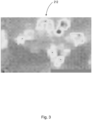
- FIG. 3 shows an example thermal image generated by a multipixel thermopile.
- Thermopile sensors are comprised of a series of thermocouples, wherein each thermocouple is a thin wire made of two materials of different thermal activity. When a temperature difference occurs between the two ends of the wire, an electrical tension develops. The hot junctions are concentrated on a very thin common absorbing area, while the cold junctions are located on a surrounding heat sink with high thermal mass.
- the multipixel thermopile may be a MLX90640.
- the MLX90640 is a fully calibrated 32 x 24 pixel thermal infrared array in an industry standard 4-lead TO39 package with a digital interface.
- the MLX90640 contains 768 far infrared sensing elements.
- An ambient sensor is also integrated to measure the ambient temperature. The output of the sensor is a thermal image as shown in FIG. 3 .
- the controller 204 may be communicatively coupled to a second sensor group 208.
- the second sensor group 208 may further include a transceiver 530 to wirelessly communicate with other components of the system 200 via network 400.
- the second sensor group 208 may have a second field of view 216.
- the second field of view 216 may correspond to the second sensor domain 220.
- the second sensor group 208 may be configured to capture a second sample set 218.
- the second sample set 218 may include samples of a different modality than the first sample set 212. The difference in modality may result from different sensor types used to collect the first sample set 212 and the second sample set 218.
- the second field of view 216 may overlap at least a portion of the first field of view 210.
- the second sensor group 208 may include at least one passive infrared (“PIR”) sensor.
- PIR sensors may be configured to capture light radiating from persons and objects in the second field of view 216 as the second sample set 218. As the PIR sensors are passive, the PIR sensors do not radiate energy for detection purposes. Rather, the PIR sensors simply detect radiant heat emitted by or reflected from objects in their field of view.
- the second sensor group 208 may include at least one microphone configured to capture audio emitted by persons and objects in the second field of view 216.
- the second sensor group 208 may include at least one camera, such as a PointGrab camera, configured to capture images of persons and objects in the second field of view 216.
- the first 206 and second 208 sensor groups may be bundled together and mounted to a luminaire or similar fixture arranged in an office space.
- the first sample set 212 may be larger in size than the second sample set 218.
- the sample set captured by a typical multipixel thermopile for an area is usually much larger than the sample set captured by a typical PIR sensor for the same area.
- the data captured by the first sensor group 212 may be significantly denser than the data captured by the second sensor group 218.
- the smaller, second sample set 218 is utilized by the system 200 to optimize the neural network 202 used to process the much larger, first sample set 212 such that the neural network 202 will function more efficiently.
- the system 200 may still function if the size of the second sample set 218 is greater than or equal to the size of the first sample set 212, the computational benefits achieved through the efficient processing of the first sample set 212 will be at least somewhat offset by the increased computation requirements associated with the larger second sample set 218.
- the controller 204 may be configured to generate of a region of interest 222 in the second sample set 218.
- a region of interest 222 may be any portion of the second sample set 218 representing portions of the area of interest to focus on during neural network processing.
- the regions of interest may be selected based on some prior knowledge of the application. For example, if the system 200 is directed to people counting, the areas of interest 222 may be near chairs or desks. Therefore, after running the image segmentation algorithm (described below) on a specific image sample, the partitions which are most relevant to the task in-hand will be selected and retrieved. For example, and as shown in FIG. 5A , regions of interest 222a-222d may include portions of the second sample set 218, including one or more chairs.
- the controller 204 may be further configured to segment the region of interest 222 from the second sample set 218. In another embodiment, the controller 204 may generate the region of interest 222 based on user input indicative of the region of interest.
- the regions of interest 222 may be segmented from the second sample set 218 based on at least an object segmentation algorithm 238.
- the object segmentation algorithm 238 defines the process of segmenting an image into multiple partitions.
- the object segmentation algorithm 238 represents each image with labels that are more meaningful and more natural to analyze. This object segmentation algorithm 238 is often used to mark objects, boundaries, and assign labels.
- state of the art image segmentation algorithms such as Mask-RCNN (Regions with Convolutional Neural Networks) may be applicable.
- the object segmentation algorithm 238 will typically be run on the entire dataset or image. Further, the object segmentation algorithm 238 may be configured to focus on particular areas within the dataset or image based on context information indicating which areas are most relevant.
- the object segmentation algorithm 238 should require significantly less processing power than a standard neural network.
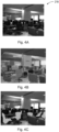
- FIG. 4A shows an image representative of the second sample set 218 to be segmented by the object segmentation algorithm 238.
- the image of the second sample set 218 may have been captured by a PointGrab camera.
- the first sensor group 206 may be a multipixel thermopile camera.
- the data captured by the multipixel thermopile camera is significantly more dense than the data captured by the PointGrab camera. Accordingly, the system 200 utilizes the data of the second sample set 218 to focus the neural network 202, allowing the neural network to process the first sample set 212 in a more efficient manner.
- the image represents a portion of an open office environment based on the field of view 216 of the second sensor group 208, including a number of objects such as desk chairs, computers, and tables.
- the image also captures aspects of the room itself, such as the floor, ceiling, walls, windows, and luminaires.
- FIG. 4B demonstrates how an object segmentation algorithm may partition the second sample set 218 into regions corresponding to office furniture and fixtures. For example, FIG. 4B shows outlines around the various objects in the office, including the desk chairs in the lower portion of the image.
- FIG. 4C demonstrates how the controller 204 may then identify regions encompassing the five desk chairs as regions of interest 222. The regions of interest 222 may be identified based on prior knowledge of the application of the system 200.
- the regions of interest 222 may be near chairs, desks, or other regions where people are likely to be present. Therefore, after running the object segmentation algorithm 238 on a specific image sample, the regions which are most relevant to the application will be identified and further processed.
- the region of interest 222 may be segmented based on at least a user preference dataset 240.
- the user preference dataset 240 may be stored in memory.
- the user preference dataset 240 may correspond to historical data of previous segmentations, as well as data input into the system directly or indirectly by a user via a user interface.
- the controller 204 may be further configured to translate the regions of interest 222a-222d from the second sensor domain 220 to the first sensor domain 214.
- This translation between the sensor domains is required due to the first 206 and second 208 sensor groups having different fields of view. Accordingly, the translation of the regions of interest 222a-222d may be based on field-of-view mapping.
- the segmented second sample set 218 contains four regions of interest 222a-222d (corresponding to the five chairs). In a people-counting application, these areas are selected as regions of interest 222a-222d due to the likelihood of a person being present in one of the chairs.
- the controller 204 translates these four regions of interest, via field-of-view mapping, into the sensor domain 214 of the first sample set 212.
- FIG. 5B shows how these translated regions of interest 232a-232d align with the first sample set 212. As the translated regions of interest 232a-232d closely correlate to the most important portions of the first sample set 212, the controller 204 can optimize the neural network 202 by focusing on the nodes 224 which process these translated regions of interest 232a-232d.
- the controller 204 may be further configured to identify one or more nodes 224 of the neural network 202 which correspond to the translated region of interest 232 based on a binary matrix 226. Identifying these nodes 224 allows the controller 204 to optimize the neural network 202 by emphasizing the most important nodes 224 for processing the samples captured by the first sensor group 206.
- the binary matrix 226 may include one or more zero entries 228 corresponding to areas outside of the translated region of interest 234. For example, in FIG. 5 , the areas outside of the translated regions of interest 234 correspond to the areas of the thermal image outside of the four rectangles. Similarly, the binary matrix 226 may include one or more non-zero entries corresponding to the areas within the translated region of interest 234.
- the binary input matrix 226 may be equal in dimension to the first sample set 212. Accordingly, the binary matrix 226 may represent the translated regions of interest 232 as ones, and the remainder of the first sensor domain 214 as zeros.
- the nodes 224 of the neural network 202 corresponding to the translated regions of interest 232 may be identified by (1) feeding the binary input matrix 226 into the neural network 202 and (2) detecting the nodes 224 of the neural network 202 which are activated by feeding and processing the binary matrix 226. As shown in FIG. 6 , the controller 204 identifies groupings of nodes 224 (illustrated by ovals) in the intermediate layers of the neural network 202 which process the non-zero entries of the binary matrix 226.
- the controller 204 is able to identify the nodes 224 of the layers (both initial and intermediate) of the neural network 202 which process the portions of the first sample set 212 corresponding to the regions of interest 222 of the second sample set 218. As described herein, the controller 204 may then optimize the neural network 202 to focus on these portions of the first sample set 212, resulting in more efficient processing. This identification enables an improvement over standard data compression protocols. While standard data compression only involves the initial layers of the neural network 202, this feeding and detection process allows for optimization of the deeper, inner layers of the neural network 202, resulting in a more focused neural network 202.
- the controller 204 may be further configured to optimize the neural network 202 by at least one of (1) increasing the weight value 230 of the nodes 224 corresponding to the one or more translated regions of interest 232 (2) decreasing the weight value 230 of the nodes 224 not corresponding to the one or more translated regions of interest 232.
- the controller 204 may focus the deeper, intermediate layers of the neural network 202 to receptive fields corresponding to relevant regions of the monitored area.
- the neural network 202 may be implemented in a workspace for activity recognition as part of a connected lighting network including the first and second sensor groups 206, 208 and one or more luminaires.
- neural network 202 may be optimized to focus on the portions of the workspace likely to experience activity at the present time. For example, if an afternoon lull in the office results in more activity in the break room, then the neural network 202 may focus on the break room by increasing the weight values 230 of the nodes 224 which process data related to the break room, and reducing the weight values of all other nodes 224. Based on this activity detection, the connected lighting system may then control one or more luminaires to turn on, turn off, dim, brighten, blink, or otherwise operate accordingly.
- a method 100 for optimizing a neural network includes capturing 102, via a first sensor group having a first field of view, a first sample set.
- the first sample set has a first sensor domain.
- the first sensor domain corresponds to the first field of view.
- the first sample set may be a thermal image corresponding to the first field of view.
- the method 100 further includes capturing 104, via a second sensor group having a second field of view, a second sample set.
- the second sample set has a second sensor domain.
- the second sensor domain corresponds to the second field of view.
- the second field of view overlaps at least a portion of the first field of view.
- the first sample set may be larger in size than the second sample set.
- the method 100 further includes generating 106 one or more regions of interest of the second sample set.
- the one or more regions of interest may be generated based on at least an object segmentation algorithm.
- the one or more regions of interest are generated based on at least a user preference dataset.
- the method 100 further includes translating 108 the one or more regions of interest from the second sensor domain to the first sensor domain.
- the method 100 further includes identifying 110 one or more nodes of the neural network which correspond to the one or more translated regions of interest.
- the neural network may include a plurality of layers. Each layer may include a plurality of nodes. Each node may have a weight value.
- the nodes of the neural network corresponding to the translated regions of interest are identified 100 by (1) feeding 118 a binary input matrix into the neural network and (2) detecting 120 the nodes of the neural network which are activated by feeding the binary matrix.
- the binary input matrix is equal in dimension to the first sample set.
- the binary input matrix includes one or more zero entries corresponding to the areas outside of the translated regions of interest.
- the binary input matrix includes one or more non-zero entries corresponding to the translated regions of interest.
- the method 100 further includes optimizing 112 the neural network by at least one of (1) increasing 114 the weight value of the nodes corresponding to the one or more translated regions of interest and (2) decreasing 116 the weight value of the nodes not corresponding to the one or more translated regions of interest.
- the weight value of the nodes not corresponding to the one or more translated regions of interest may be set to 0.
- the phrase "at least one,” in reference to a list of one or more elements, should be understood to mean at least one element selected from any one or more of the elements in the list of elements, but not necessarily including at least one of each and every element specifically listed within the list of elements and not excluding any combinations of elements in the list of elements.
- This definition also allows that elements may optionally be present other than the elements specifically identified within the list of elements to which the phrase "at least one" refers, whether related or unrelated to those elements specifically identified.
- the present disclosure may be implemented as a system, a method, and/or a computer program product at any possible technical detail level of integration
- the computer program product may include a computer readable storage medium (or media) having computer readable program instructions thereon for causing a processor to carry out aspects of the present disclosure
- the computer readable storage medium can be a tangible device that can retain and store instructions for use by an instruction execution device.
- the computer readable storage medium may be, for example, but is not limited to, an electronic storage device, a magnetic storage device, an optical storage device, an electromagnetic storage device, a semiconductor storage device, or any suitable combination of the foregoing.
- a nonexhaustive list of more specific examples of the computer readable storage medium includes the following: a portable computer diskette, a hard disk, a random access memory (RAM), a read-only memory (ROM), an erasable programmable read-only memory (EPROM or Flash memory), a static random access memory (SRAM), a portable compact disc read-only memory (CD-ROM), a digital versatile disk (DVD), a memory stick, a floppy disk, a mechanically encoded device such as punch-cards or raised structures in a groove having instructions recorded thereon, and any suitable combination of the foregoing.
- RAM random access memory
- ROM read-only memory
- EPROM or Flash memory erasable programmable read-only memory
- SRAM static random access memory
- CD-ROM compact disc read-only memory
- DVD digital versatile disk
- memory stick a floppy disk
- mechanically encoded device such as punch-cards or raised structures in a groove having instructions recorded thereon
- a computer readable storage medium is not to be construed as being transitory signals per se, such as radio waves or other freely propagating electromagnetic waves, electromagnetic waves propagating through a waveguide or other transmission media (e.g., light pulses passing through a fiber-optic cable), or electrical signals transmitted through a wire.
- Computer readable program instructions described herein can be downloaded to respective computing/processing devices from a computer readable storage medium or to an external computer or external storage device via a network, for example, the Internet, a local area network, a wide area network and/or a wireless network.
- the network may comprise copper transmission cables, optical transmission fibers, wireless transmission, routers, firewalls, switches, gateway computers and/or edge servers.
- a network adapter card or network interface in each computing/processing device receives computer readable program instructions from the network and forwards the computer readable program instructions for storage in a computer readable storage medium within the respective computing/processing device.
- Computer readable program instructions for carrying out operations of the present disclosure may be assembler instructions, instruction-set-architecture (ISA) instructions, machine instructions, machine dependent instructions, microcode, firmware instructions, state-setting data, configuration data for integrated circuitry, or either source code or object code written in any combination of one or more programming languages, including an object oriented programming language such as Smalltalk, C++, or the like, and procedural programming languages, such as the "C" programming language or similar programming languages.
- the computer readable program instructions may execute entirely on the user's computer, partly on the user's computer, as a stand-alone software package, partly on the user's computer and partly on a remote computer or entirely on the remote computer or server.
- the remote computer may be connected to the user's computer through any type of network, including a local area network (LAN) or a wide area network (WAN), or the connection may be made to an external computer (for example, through the Internet using an Internet Service Provider).
- electronic circuitry including, for example, programmable logic circuitry, field-programmable gate arrays (FPGA), or programmable logic arrays (PLA) may execute the computer readable program instructions by utilizing state information of the computer readable program instructions to personalize the electronic circuitry, in order to perform aspects of the present disclosure.
- the computer readable program instructions may be provided to a processor of a, special purpose computer, or other programmable data processing apparatus to produce a machine, such that the instructions, which execute via the processor of the computer or other programmable data processing apparatus, create means for implementing the functions/acts specified in the flowchart and/or block diagram block or blocks.
- These computer readable program instructions may also be stored in a computer readable storage medium that can direct a computer, a programmable data processing apparatus, and/or other devices to function in a particular manner, such that the computer readable storage medium having instructions stored therein comprises an article of manufacture including instructions which implement aspects of the function/act specified in the flowchart and/or block diagram or blocks.
- the computer readable program instructions may also be loaded onto a computer, other programmable data processing apparatus, or other device to cause a series of operational steps to be performed on the computer, other programmable apparatus or other device to produce a computer implemented process, such that the instructions which execute on the computer, other programmable apparatus, or other device implement the functions/acts specified in the flowchart and/or block diagram block or blocks.
- each block in the flowchart or block diagrams may represent a module, segment, or portion of instructions, which comprises one or more executable instructions for implementing the specified logical function(s).
- the functions noted in the blocks may occur out of the order noted in the Figures.
- two blocks shown in succession may, in fact, be executed substantially concurrently, or the blocks may sometimes be executed in the reverse order, depending upon the functionality involved.
Landscapes
- Engineering & Computer Science (AREA)
- Theoretical Computer Science (AREA)
- General Physics & Mathematics (AREA)
- Physics & Mathematics (AREA)
- Multimedia (AREA)
- Computer Vision & Pattern Recognition (AREA)
- Evolutionary Computation (AREA)
- Artificial Intelligence (AREA)
- Data Mining & Analysis (AREA)
- General Health & Medical Sciences (AREA)
- Health & Medical Sciences (AREA)
- Life Sciences & Earth Sciences (AREA)
- Software Systems (AREA)
- Medical Informatics (AREA)
- Databases & Information Systems (AREA)
- Computing Systems (AREA)
- General Engineering & Computer Science (AREA)
- Bioinformatics & Computational Biology (AREA)
- Bioinformatics & Cheminformatics (AREA)
- Evolutionary Biology (AREA)
- Biomedical Technology (AREA)
- Molecular Biology (AREA)
- Biodiversity & Conservation Biology (AREA)
- Image Analysis (AREA)
Description
- The present disclosure is directed generally to optimizing neural networks through fusion of data captured by sensors of different modes.
- Deep learning neural networks typically include multiple intermediate layers of nodes resulting in large and complicated receptive fields and activation maps. However, in many cases, the majority of the data in these receptive fields and activation maps will be unnecessary for the goal of the network. For example, a thermal image analyzed by a neural network trained for activity detection may only contain relevant information in its upper-right quadrant. Thus, the processing of the receptive fields corresponding to the other three quadrants results in wasted computing time and energy. Accordingly, there is a need for (1) identifying relevant portions of the receptive field and (2) focusing on the relevant portions.
-
US 2016/003493A1 discloses a passive infrared (PIR) motion sensor system which includes a non-contact thermopile detector for capturing infrared energy from a focused upon area in a room or zone deemed most likely to be occupied and generating a thermopile temperature signal therefrom, a pyroelectric detector for viewing through multiple passive lens elements (lenslets) that form PIR beams from a large portion of the room or zone and generating a pyroelectric signal therefrom, an ambient temperature sensor for sensing an ambient temperature in the room or zone and generating an ambient temperature signal detection threshold that is utilized in PIR detection therefrom and a microcomputer configured to process the thermopile temperature signal, the pyroelectric signal and the ambient temperature signal and determine whether the room or zone is occupied or unoccupied. - Connected lighting systems include sensor bundles to capture samples used to control their associated luminaires. The sensor bundles may include different types of sensors, such as thermopile sensors and passive infrared (PIR) sensors. The connected lighting system may implement a neural network to process the samples collected by one of the sensor modes to control its associated luminaire. For example, the neural network may detect activity in a defined space by processing the data collected by the thermopile sensors.
- The present invention is a method of optimizing a neural network according to claim 1 and a system for optimizing a neural network according to claim 9.
- In the drawings, like reference characters generally refer to the same parts throughout the different views. Also, the drawings are not necessarily to scale, emphasis instead generally being placed upon illustrating the principles of the various embodiments.
-
Fig. 1 is a schematic of a system for optimizing a neural network, in accordance with an example. -
Fig. 2 is a further schematic of a system for optimizing a neural network, in accordance with an example. -
Fig. 3 is a thermal image generated by one or more multipixel thermopiles, in accordance with an example. -
Figs. 4A-4C demonstrates how the system identifies regions of interest in data collected by the second sensor group, in accordance with an example. -
Figs. 5A and 5B demonstrates how the system translates the identified regions of interest, in accordance with an example. -
Fig. 6 demonstrates how the system optimizes a neural network based on data captured by a passive infrared sensor, in accordance with an example. -
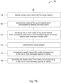
Figs. 7A and7B are portions of a flowchart of a method for optimizing a neural network, in accordance with an example. - The present disclosure is directed generally to optimizing a neural network through fusion of data captured by sensors of different modes. The system utilizes two modalities of sensors of varying granularity, such as a first group of thermopiles and a second group of passive infrared (PIR) sensors. The system locates one or more regions of interest in the data captured by the second group, and translates this data from the sensor domain of the second group to the sensor domain of the first. The system then creates a binary matrix corresponding to the translated data. The binary matrix is loaded into the neural network to identify the nodes of the network which correspond to the translated regions of interest. Accordingly, these identified nodes also correspond to the relevant receptive fields of the thermopile data to be processed by the network. The system may then optimize the neural network by increasing or decreasing weight values of the nodes of the network based on relevance. Once the neural network is optimized, the data captured by the first group of sensors may be processed in a more efficient manner by focusing on the most relevant receptive fields of the data captured by the first group of thermopiles.
- Referring to
FIGS. 1 and2 , in one aspect, asystem 200 for optimizing aneural network 202 is provided. Theneural network 202 may be a convolutional neural network. Theneural network 202 may include a plurality of layers. Each layer may include a plurality ofnodes 224. Eachnode 224 may have aweight value 230. - In a preferred embodiment, the
neural network 202 may be utilized for activity detection in a detection area, such as an office space. Additionally, other use cases forneural networks 202 are known, such as occupancy detection, people counting, and facial detection. Variations of the present systems and methods can generally be used in almost any object detection application with two sources of imagery. For example, in a people counting application, a system may use thermopile samples to identify regions of interest in a neural network for processing RGB (Red-Green-Blue) images. - With respect to activity detection, the
neural network 202 is configured to process samples collected by one or more sensors monitoring the detection area. These sensors may be embedded in luminaires arranged in a connected lighting system in the office space. - The
system 200 may include acontroller 204, afirst sensor group 206, and asecond sensor group 208 capable of communication via wired and/orwireless network 500. With reference toFIG. 1 , thecontroller 204 may include amemory 300, aprocessor 400, and atransceiver 510. Thememory 300 andprocessor 400 may be communicatively coupled via a bus to facilitate processing of data stored inmemory 300. Transceiver 510 may be used to receive samples from the first 206 and second 208 sensor group via thenetwork 500. The data received by thetransceiver 510 may be stored inmemory 300 and/or processed byprocessor 400. In an example, thetransceiver 510 may facilitate a wireless connection between thecontroller 204 and thenetwork 500. - The
network 500 may be configured to facilitate communication between thecontroller 204, thefirst sensor group 206, thesecond sensor group 208, and/or any combination thereof. Thenetwork 400 may be a wired and/or wireless network following communication protocols such as Bluetooth, Wi-Fi, Zigbee, and/or other appropriate communication protocols. In an example, thesensors network 500, thesamples controller 204 for storage inmemory 300 and/or processing by theprocessor 400. - The
controller 204 may be communicatively coupled to afirst sensor group 206 over a wired and/orwireless network 500 as described herein. Thefirst sensor group 206 may further include atransceiver 520 to wirelessly communicate with other components of thesystem 200 vianetwork 400. - The
first sensor group 206 may have a first field ofview 210. As shown inFIG. 2 , the first field ofview 210 defines the extent of the observable environment, such as an office space, captured by thefirst sensor group 206. The first field ofview 210 may be adjusted in a number of ways, including via placement or orientation of thesensors 206, or by adjusting the physical and/or digital characteristics of thesensors 206. - The
first sensor group 206 may be configured to capture afirst sample set 212. Thefirst sample set 212 includes data to be processed by theneural network 202 for one or more purposes, such as activity detection. The second sample set 218, described below, is used by thesystem 202 to optimize theneural network 202 such that thefirst sample set 212 is processed in a more efficient manner. - The first sample set 212 has a
first sensor domain 214. Thefirst sensor domain 214 is defined by the the first field ofview 210 of thefirst sensor group 206. Accordingly, the dimensions of thefirst sensor domain 214 represent the extent of the observable environment represented by the first sample set 212. - The
first sensor group 206 may include at least one multipixel thermopile. The first sample set 212 may be a thermal image corresponding to the first field ofview 210.FIG. 3 shows an example thermal image generated by a multipixel thermopile. Thermopile sensors are comprised of a series of thermocouples, wherein each thermocouple is a thin wire made of two materials of different thermal activity. When a temperature difference occurs between the two ends of the wire, an electrical tension develops. The hot junctions are concentrated on a very thin common absorbing area, while the cold junctions are located on a surrounding heat sink with high thermal mass. In one example, the multipixel thermopile may be a MLX90640. The MLX90640 is a fully calibrated 32 x 24 pixel thermal infrared array in an industry standard 4-lead TO39 package with a digital interface. The MLX90640 contains 768 far infrared sensing elements. An ambient sensor is also integrated to measure the ambient temperature. The output of the sensor is a thermal image as shown inFIG. 3 . - The
controller 204 may be communicatively coupled to asecond sensor group 208. Thesecond sensor group 208 may further include atransceiver 530 to wirelessly communicate with other components of thesystem 200 vianetwork 400. - The
second sensor group 208 may have a second field ofview 216. The second field ofview 216 may correspond to thesecond sensor domain 220. Thesecond sensor group 208 may be configured to capture a second sample set 218. The second sample set 218 may include samples of a different modality than the first sample set 212. The difference in modality may result from different sensor types used to collect the first sample set 212 and the second sample set 218. As shown inFIG. 2 , the second field ofview 216 may overlap at least a portion of the first field ofview 210. - In a preferred embodiment, the
second sensor group 208 may include at least one passive infrared ("PIR") sensor. The PIR sensors may be configured to capture light radiating from persons and objects in the second field ofview 216 as the second sample set 218. As the PIR sensors are passive, the PIR sensors do not radiate energy for detection purposes. Rather, the PIR sensors simply detect radiant heat emitted by or reflected from objects in their field of view. - In a further example, the
second sensor group 208 may include at least one microphone configured to capture audio emitted by persons and objects in the second field ofview 216. In an even further example, thesecond sensor group 208 may include at least one camera, such as a PointGrab camera, configured to capture images of persons and objects in the second field ofview 216. In another example, the first 206 and second 208 sensor groups may be bundled together and mounted to a luminaire or similar fixture arranged in an office space. - In a preferred example, the first sample set 212 may be larger in size than the second sample set 218. For example, the sample set captured by a typical multipixel thermopile for an area is usually much larger than the sample set captured by a typical PIR sensor for the same area. In other words, the data captured by the
first sensor group 212 may be significantly denser than the data captured by thesecond sensor group 218. In this preferred example, the smaller, second sample set 218 is utilized by thesystem 200 to optimize theneural network 202 used to process the much larger, first sample set 212 such that theneural network 202 will function more efficiently. While thesystem 200 may still function if the size of the second sample set 218 is greater than or equal to the size of the first sample set 212, the computational benefits achieved through the efficient processing of the first sample set 212 will be at least somewhat offset by the increased computation requirements associated with the larger second sample set 218. - The
controller 204 may be configured to generate of a region ofinterest 222 in the second sample set 218. A region ofinterest 222 may be any portion of the second sample set 218 representing portions of the area of interest to focus on during neural network processing. The regions of interest may be selected based on some prior knowledge of the application. For example, if thesystem 200 is directed to people counting, the areas ofinterest 222 may be near chairs or desks. Therefore, after running the image segmentation algorithm (described below) on a specific image sample, the partitions which are most relevant to the task in-hand will be selected and retrieved. For example, and as shown inFIG. 5A , regions ofinterest 222a-222d may include portions of the second sample set 218, including one or more chairs. In order to generate the region ofinterest 222, thecontroller 204 may be further configured to segment the region ofinterest 222 from the second sample set 218. In another embodiment, thecontroller 204 may generate the region ofinterest 222 based on user input indicative of the region of interest. - In one example, the regions of
interest 222 may be segmented from the second sample set 218 based on at least anobject segmentation algorithm 238. Theobject segmentation algorithm 238 defines the process of segmenting an image into multiple partitions. Theobject segmentation algorithm 238 represents each image with labels that are more meaningful and more natural to analyze. Thisobject segmentation algorithm 238 is often used to mark objects, boundaries, and assign labels. In the present application, state of the art image segmentation algorithms such as Mask-RCNN (Regions with Convolutional Neural Networks) may be applicable. Theobject segmentation algorithm 238 will typically be run on the entire dataset or image. Further, theobject segmentation algorithm 238 may be configured to focus on particular areas within the dataset or image based on context information indicating which areas are most relevant. Theobject segmentation algorithm 238 should require significantly less processing power than a standard neural network. -
FIG. 4A shows an image representative of the second sample set 218 to be segmented by theobject segmentation algorithm 238. In this example, the image of the second sample set 218 may have been captured by a PointGrab camera. Further to this example, thefirst sensor group 206 may be a multipixel thermopile camera. The data captured by the multipixel thermopile camera is significantly more dense than the data captured by the PointGrab camera. Accordingly, thesystem 200 utilizes the data of the second sample set 218 to focus theneural network 202, allowing the neural network to process the first sample set 212 in a more efficient manner. - As seen in
FIG. 4A , the image represents a portion of an open office environment based on the field ofview 216 of thesecond sensor group 208, including a number of objects such as desk chairs, computers, and tables. The image also captures aspects of the room itself, such as the floor, ceiling, walls, windows, and luminaires.FIG. 4B demonstrates how an object segmentation algorithm may partition the second sample set 218 into regions corresponding to office furniture and fixtures. For example,FIG. 4B shows outlines around the various objects in the office, including the desk chairs in the lower portion of the image.FIG. 4C demonstrates how thecontroller 204 may then identify regions encompassing the five desk chairs as regions ofinterest 222. The regions ofinterest 222 may be identified based on prior knowledge of the application of thesystem 200. For example, if thesystem 200 is directed to people counting, the regions ofinterest 222 may be near chairs, desks, or other regions where people are likely to be present. Therefore, after running theobject segmentation algorithm 238 on a specific image sample, the regions which are most relevant to the application will be identified and further processed. - In a further example, the region of
interest 222 may be segmented based on at least a user preference dataset 240. The user preference dataset 240 may be stored in memory. The user preference dataset 240 may correspond to historical data of previous segmentations, as well as data input into the system directly or indirectly by a user via a user interface. - With reference to
FIGS. 5A and 5B , thecontroller 204 may be further configured to translate the regions ofinterest 222a-222d from thesecond sensor domain 220 to thefirst sensor domain 214. This translation between the sensor domains is required due to the first 206 and second 208 sensor groups having different fields of view. Accordingly, the translation of the regions ofinterest 222a-222d may be based on field-of-view mapping. - As shown in
FIG. 5A , the segmented second sample set 218 contains four regions ofinterest 222a-222d (corresponding to the five chairs). In a people-counting application, these areas are selected as regions ofinterest 222a-222d due to the likelihood of a person being present in one of the chairs. Thecontroller 204 translates these four regions of interest, via field-of-view mapping, into thesensor domain 214 of the first sample set 212.FIG. 5B shows how these translated regions ofinterest 232a-232d align with the first sample set 212. As the translated regions ofinterest 232a-232d closely correlate to the most important portions of the first sample set 212, thecontroller 204 can optimize theneural network 202 by focusing on thenodes 224 which process these translated regions ofinterest 232a-232d. - The
controller 204 may be further configured to identify one ormore nodes 224 of theneural network 202 which correspond to the translated region ofinterest 232 based on abinary matrix 226. Identifying thesenodes 224 allows thecontroller 204 to optimize theneural network 202 by emphasizing the mostimportant nodes 224 for processing the samples captured by thefirst sensor group 206. Thebinary matrix 226 may include one or more zeroentries 228 corresponding to areas outside of the translated region ofinterest 234. For example, inFIG. 5 , the areas outside of the translated regions ofinterest 234 correspond to the areas of the thermal image outside of the four rectangles. Similarly, thebinary matrix 226 may include one or more non-zero entries corresponding to the areas within the translated region ofinterest 234. Thebinary input matrix 226 may be equal in dimension to the first sample set 212. Accordingly, thebinary matrix 226 may represent the translated regions ofinterest 232 as ones, and the remainder of thefirst sensor domain 214 as zeros. - Once the
binary matrix 226 is generated, thenodes 224 of theneural network 202 corresponding to the translated regions ofinterest 232 may be identified by (1) feeding thebinary input matrix 226 into theneural network 202 and (2) detecting thenodes 224 of theneural network 202 which are activated by feeding and processing thebinary matrix 226. As shown inFIG. 6 , thecontroller 204 identifies groupings of nodes 224 (illustrated by ovals) in the intermediate layers of theneural network 202 which process the non-zero entries of thebinary matrix 226. - By performing the above feeding and detection steps, the
controller 204 is able to identify thenodes 224 of the layers (both initial and intermediate) of theneural network 202 which process the portions of the first sample set 212 corresponding to the regions ofinterest 222 of the second sample set 218. As described herein, thecontroller 204 may then optimize theneural network 202 to focus on these portions of the first sample set 212, resulting in more efficient processing. This identification enables an improvement over standard data compression protocols. While standard data compression only involves the initial layers of theneural network 202, this feeding and detection process allows for optimization of the deeper, inner layers of theneural network 202, resulting in a more focusedneural network 202. - The
controller 204 may be further configured to optimize theneural network 202 by at least one of (1) increasing theweight value 230 of thenodes 224 corresponding to the one or more translated regions of interest 232 (2) decreasing theweight value 230 of thenodes 224 not corresponding to the one or more translated regions ofinterest 232. By increasing and/or decreasing the weight values 230 of certain groupings ofnodes 224, thecontroller 204 may focus the deeper, intermediate layers of theneural network 202 to receptive fields corresponding to relevant regions of the monitored area. For example, theneural network 202 may be implemented in a workspace for activity recognition as part of a connected lighting network including the first andsecond sensor groups neural network 202 may be optimized to focus on the portions of the workspace likely to experience activity at the present time. For example, if an afternoon lull in the office results in more activity in the break room, then theneural network 202 may focus on the break room by increasing the weight values 230 of thenodes 224 which process data related to the break room, and reducing the weight values of allother nodes 224. Based on this activity detection, the connected lighting system may then control one or more luminaires to turn on, turn off, dim, brighten, blink, or otherwise operate accordingly. - Referring to
FIGS. 7A and7B , in another aspect, amethod 100 for optimizing a neural network is provided. Themethod 100 includes capturing 102, via a first sensor group having a first field of view, a first sample set. The first sample set has a first sensor domain. The first sensor domain corresponds to the first field of view. The first sample set may be a thermal image corresponding to the first field of view. - The
method 100 further includes capturing 104, via a second sensor group having a second field of view, a second sample set. The second sample set has a second sensor domain. The second sensor domain corresponds to the second field of view. The second field of view overlaps at least a portion of the first field of view. The first sample set may be larger in size than the second sample set. - The
method 100 further includes generating 106 one or more regions of interest of the second sample set. The one or more regions of interest may be generated based on at least an object segmentation algorithm. The one or more regions of interest are generated based on at least a user preference dataset. - The
method 100 further includes translating 108 the one or more regions of interest from the second sensor domain to the first sensor domain. - The
method 100 further includes identifying 110 one or more nodes of the neural network which correspond to the one or more translated regions of interest. The neural network may include a plurality of layers. Each layer may include a plurality of nodes. Each node may have a weight value. - The nodes of the neural network corresponding to the translated regions of interest are identified 100 by (1) feeding 118 a binary input matrix into the neural network and (2) detecting 120 the nodes of the neural network which are activated by feeding the binary matrix. The binary input matrix is equal in dimension to the first sample set. The binary input matrix includes one or more zero entries corresponding to the areas outside of the translated regions of interest. The binary input matrix includes one or more non-zero entries corresponding to the translated regions of interest.
- The
method 100 further includes optimizing 112 the neural network by at least one of (1) increasing 114 the weight value of the nodes corresponding to the one or more translated regions of interest and (2) decreasing 116 the weight value of the nodes not corresponding to the one or more translated regions of interest. The weight value of the nodes not corresponding to the one or more translated regions of interest may be set to 0. - All definitions, as defined and used herein, should be understood to control over dictionary definitions, definitions in documents incorporated by reference, and/or ordinary meanings of the defined terms.
- The indefinite articles "a" and "an," as used herein in the specification and in the claims, unless clearly indicated to the contrary, should be understood to mean "at least one."
- The phrase "and/or," as used herein in the specification and in the claims, should be understood to mean "either or both" of the elements so conjoined, i.e., elements that are conjunctively present in some cases and disjunctively present in other cases. Multiple elements listed with "and/or" should be construed in the same fashion, i.e., "one or more" of the elements so conjoined. Other elements may optionally be present other than the elements specifically identified by the "and/or" clause, whether related or unrelated to those elements specifically identified.
- As used herein in the specification and in the claims, "or" should be understood to have the same meaning as "and/or" as defined above. For example, when separating items in a list, "or" or "and/or" shall be interpreted as being inclusive, i.e., the inclusion of at least one, but also including more than one, of a number or list of elements, and, optionally, additional unlisted items. Only terms clearly indicated to the contrary, such as "only one of" or "exactly one of," or, when used in the claims, "consisting of," will refer to the inclusion of exactly one element of a number or list of elements. In general, the term "or" as used herein shall only be interpreted as indicating exclusive alternatives (i.e. "one or the other but not both") when preceded by terms of exclusivity, such as "either," "one of," "only one of," or "exactly one of."
- As used herein in the specification and in the claims, the phrase "at least one," in reference to a list of one or more elements, should be understood to mean at least one element selected from any one or more of the elements in the list of elements, but not necessarily including at least one of each and every element specifically listed within the list of elements and not excluding any combinations of elements in the list of elements. This definition also allows that elements may optionally be present other than the elements specifically identified within the list of elements to which the phrase "at least one" refers, whether related or unrelated to those elements specifically identified.
- It should also be understood that, unless clearly indicated to the contrary, in any methods claimed herein that include more than one step or act, the order of the steps or acts of the method is not necessarily limited to the order in which the steps or acts of the method are recited.
- In the claims, as well as in the specification above, all transitional phrases such as "comprising," "including," "carrying," "having," "containing," "involving," "holding," "composed of," and the like are to be understood to be open-ended, i.e., to mean including but not limited to. Only the transitional phrases "consisting of" and "consisting essentially of" shall be closed or semi-closed transitional phrases, respectively.
- The above-described examples of the described subject matter can be implemented in any of numerous ways. For example, some aspects may be implemented using hardware, software or a combination thereof. When any aspect is implemented at least in part in software, the software code can be executed on any suitable processor or collection of processors, whether provided in a single device or computer or distributed among multiple devices/computers.
- The present disclosure may be implemented as a system, a method, and/or a computer program product at any possible technical detail level of integration. The computer program product may include a computer readable storage medium (or media) having computer readable program instructions thereon for causing a processor to carry out aspects of the present disclosure.
- The computer readable storage medium can be a tangible device that can retain and store instructions for use by an instruction execution device. The computer readable storage medium may be, for example, but is not limited to, an electronic storage device, a magnetic storage device, an optical storage device, an electromagnetic storage device, a semiconductor storage device, or any suitable combination of the foregoing. A nonexhaustive list of more specific examples of the computer readable storage medium includes the following: a portable computer diskette, a hard disk, a random access memory (RAM), a read-only memory (ROM), an erasable programmable read-only memory (EPROM or Flash memory), a static random access memory (SRAM), a portable compact disc read-only memory (CD-ROM), a digital versatile disk (DVD), a memory stick, a floppy disk, a mechanically encoded device such as punch-cards or raised structures in a groove having instructions recorded thereon, and any suitable combination of the foregoing. A computer readable storage medium, as used herein, is not to be construed as being transitory signals per se, such as radio waves or other freely propagating electromagnetic waves, electromagnetic waves propagating through a waveguide or other transmission media (e.g., light pulses passing through a fiber-optic cable), or electrical signals transmitted through a wire.
- Computer readable program instructions described herein can be downloaded to respective computing/processing devices from a computer readable storage medium or to an external computer or external storage device via a network, for example, the Internet, a local area network, a wide area network and/or a wireless network. The network may comprise copper transmission cables, optical transmission fibers, wireless transmission, routers, firewalls, switches, gateway computers and/or edge servers. A network adapter card or network interface in each computing/processing device receives computer readable program instructions from the network and forwards the computer readable program instructions for storage in a computer readable storage medium within the respective computing/processing device.
- Computer readable program instructions for carrying out operations of the present disclosure may be assembler instructions, instruction-set-architecture (ISA) instructions, machine instructions, machine dependent instructions, microcode, firmware instructions, state-setting data, configuration data for integrated circuitry, or either source code or object code written in any combination of one or more programming languages, including an object oriented programming language such as Smalltalk, C++, or the like, and procedural programming languages, such as the "C" programming language or similar programming languages. The computer readable program instructions may execute entirely on the user's computer, partly on the user's computer, as a stand-alone software package, partly on the user's computer and partly on a remote computer or entirely on the remote computer or server. In the latter scenario, the remote computer may be connected to the user's computer through any type of network, including a local area network (LAN) or a wide area network (WAN), or the connection may be made to an external computer (for example, through the Internet using an Internet Service Provider). In some examples, electronic circuitry including, for example, programmable logic circuitry, field-programmable gate arrays (FPGA), or programmable logic arrays (PLA) may execute the computer readable program instructions by utilizing state information of the computer readable program instructions to personalize the electronic circuitry, in order to perform aspects of the present disclosure.
- Aspects of the present disclosure are described herein with reference to flowchart illustrations and/or block diagrams of methods, apparatus (systems), and computer program products according to examples of the disclosure. It will be understood that each block of the flowchart illustrations and/or block diagrams, and combinations of blocks in the flowchart illustrations and/or block diagrams, can be implemented by computer readable program instructions.
- The computer readable program instructions may be provided to a processor of a, special purpose computer, or other programmable data processing apparatus to produce a machine, such that the instructions, which execute via the processor of the computer or other programmable data processing apparatus, create means for implementing the functions/acts specified in the flowchart and/or block diagram block or blocks. These computer readable program instructions may also be stored in a computer readable storage medium that can direct a computer, a programmable data processing apparatus, and/or other devices to function in a particular manner, such that the computer readable storage medium having instructions stored therein comprises an article of manufacture including instructions which implement aspects of the function/act specified in the flowchart and/or block diagram or blocks.
- The computer readable program instructions may also be loaded onto a computer, other programmable data processing apparatus, or other device to cause a series of operational steps to be performed on the computer, other programmable apparatus or other device to produce a computer implemented process, such that the instructions which execute on the computer, other programmable apparatus, or other device implement the functions/acts specified in the flowchart and/or block diagram block or blocks.
- The flowchart and block diagrams in the Figures illustrate the architecture, functionality, and operation of possible implementations of systems, methods, and computer program products according to various examples of the present disclosure. In this regard, each block in the flowchart or block diagrams may represent a module, segment, or portion of instructions, which comprises one or more executable instructions for implementing the specified logical function(s). In some alternative implementations, the functions noted in the blocks may occur out of the order noted in the Figures. For example, two blocks shown in succession may, in fact, be executed substantially concurrently, or the blocks may sometimes be executed in the reverse order, depending upon the functionality involved. It will also be noted that each block of the block diagrams and/or flowchart illustration, and combinations of blocks in the block diagrams and/or flowchart illustration, can be implemented by special purpose hardware-based systems that perform the specified functions or acts or carry out combinations of special purpose hardware and computer instructions.
- While various examples have been described and illustrated herein, those of ordinary skill in the art will readily envision a variety of other means and/or structures for performing the function and/or obtaining the results and/or one or more of the advantages described herein, and each of such variations and/or modifications is deemed to be within the scope of the examples described herein. More generally, those skilled in the art will readily appreciate that all parameters, dimensions, materials, and configurations described herein are meant to be exemplary and that the actual parameters, dimensions, materials, and/or configurations will depend upon the specific application or applications for which the teachings is/are used. Those skilled in the art will recognize, or be able to ascertain using no more than routine experimentation, many equivalents to the specific examples described herein. It is, therefore, to be understood that the foregoing examples are presented by way of example only and that, within the scope of the appended claims, examples may be practiced otherwise than as specifically described and claimed. Examples of the present disclosure are directed to each individual feature, system, article, material, kit, and/or method described herein. In addition, any combination of two or more such features, systems, articles, materials, kits, and/or methods, if such features, systems, articles, materials, kits, and/or methods are not mutually inconsistent, is included within the scope of the present disclosure.
Claims (11)
- A method (100) for optimizing a neural network, comprising:capturing (102), via a first sensor group having a first field of view, a first sample set having a first sensor domain corresponding to the first field of view;capturing (104), via a second sensor group having a second field of view, a second sample set having a second sensor domain corresponding to the second field of view, wherein the second field of view overlaps at least a portion of the first field of view;generating (106) one or more regions of interest of the second sample set; translating (108) the one or more regions of interest from the second sensor domain to the first sensor domain;identifying (110) one or more nodes of the neural network which correspond to the one or more translated regions of interest, wherein each node has a weight value; andoptimizing (112) the neural network by at least one of:increasing (114) the weight value of the nodes corresponding to the one or more translated regions of interest; anddecreasing (116) the weight value of the nodes not corresponding to the one or more translated regions of interest;wherein the nodes of the neural network corresponding to the translated regions of interest are identified by:feeding (118) a binary input matrix into the neural network; anddetecting (120) the nodes of the neural network which are activated by feeding the binary matrix; andwherein the binary input matrix is equal in dimension to the first sample set; wherein the binary input matrix comprises one or more zero entries corresponding to the areas outside of the translated regions of interest; and wherein the binary input matrix comprises one or more non-zero entries corresponding to the translated regions of interest.
- The method (100) of claim 1, wherein the weight value of the nodes not corresponding to the one or more translated regions of interest is set to 0.
- The method (100) of claim 1, wherein the first sample set is larger in size than the second sample set.
- The method (100) of claim 1, wherein the first sample set is a thermal image corresponding to the first field of view.
- The method (100) of claim 1, wherein the one or more regions of interest are generated (106) based on at least an object segmentation algorithm.
- The method (100) of claim 1, wherein the one or more regions of interest are generated (106) based on at least a user preference dataset.
- The method (100) of claim 1, wherein the neural network is configured to detect activity in the first field of view of the first sensor group.
- The method (100) of claim 7, wherein one or more luminaires of a connected lighting system are controlled based on the detection of activity in the first field of view of the first sensor group.
- A system (200) for optimizing a neural network (202), comprising:a controller (204) communicatively coupled to a first sensor group (206) and a second sensor group (208), the first sensor group (206) having a first field of view (210) and configured to capture a first sample set (212) having a first sensor domain (214) corresponding to the first field of view (210), the second sensor group (208) having a second field of view (216) and configured to capture a second sample set (218) having a second sensor domain (220) corresponding to the second field of view (218), wherein the second field of view (216) overlaps at least a portion of the first field of view (210); andwherein the controller (204) is configured to:wherein the nodes of the neural network corresponding to the translated regions of interest are identified by:segment the region of interest (222) from the second sample set (220);translate the region of interest (222) from the second sensor domain (218) to the first sensor domain (214);identify one or more nodes (224) of the neural network (202) which correspond to the translated region of interest (232) based on a binary matrix (226), wherein the binary matrix (226) comprises one or more zero entries (228) corresponding to areas outside of the translated region of interest (234), and wherein each node has a weight value (230); andoptimize the neural network (202) by at least one of:increasing the weight value (230) of the nodes (224) corresponding to the one or more translated regions of interest (222); anddecreasing the weight value (230) of the nodes (224) not corresponding to the one or more translated regions of interest (222);feeding (118) a binary input matrix into the neural network; anddetecting (120) the nodes of the neural network which are activated by feeding the binary matrix; andwherein the binary input matrix is equal in dimension to the first sample set; wherein the binary input matrix comprises one or more zero entries corresponding to the areas outside of the translated regions of interest; and wherein the binary input matrix comprises one or more non-zero entries corresponding to the translated regions of interest.
- The system (200) of claim 9, wherein the first sensor group (206) comprises at least one multipixel thermopile.
- The system (200) of claim 9, wherein the second sensor group (208) comprises at least one passive infrared sensor, one microphone and/or one camera.
Applications Claiming Priority (3)
| Application Number | Priority Date | Filing Date | Title |
|---|---|---|---|
| US202063044037P | 2020-06-25 | 2020-06-25 | |
| EP20198009 | 2020-09-24 | ||
| PCT/EP2021/066675 WO2021259806A1 (en) | 2020-06-25 | 2021-06-18 | System and methods to optimize neural networks using sensor fusion |
Publications (2)
| Publication Number | Publication Date |
|---|---|
| EP4172848A1 EP4172848A1 (en) | 2023-05-03 |
| EP4172848B1 true EP4172848B1 (en) | 2023-10-11 |
Family
ID=76483319
Family Applications (1)
| Application Number | Title | Priority Date | Filing Date |
|---|---|---|---|
| EP21732924.2A Active EP4172848B1 (en) | 2020-06-25 | 2021-06-18 | System and methods to optimize neural networks using sensor fusion |
Country Status (3)
| Country | Link |
|---|---|
| US (1) | US12347175B2 (en) |
| EP (1) | EP4172848B1 (en) |
| WO (1) | WO2021259806A1 (en) |
Citations (7)
| Publication number | Priority date | Publication date | Assignee | Title |
|---|---|---|---|---|
| US20160003493A1 (en) | 2014-07-03 | 2016-01-07 | Fred Katz | Multi-mode Passive Infrared Occupancy Sensor System For Energy Saving Application |
| US20190347538A1 (en) | 2018-05-11 | 2019-11-14 | Qualcomm Incorporated | Neural network with frozen nodes |
| US20200012898A1 (en) | 2018-07-03 | 2020-01-09 | General Electric Company | Classification based on annotation information |
| US20200012904A1 (en) | 2018-07-03 | 2020-01-09 | General Electric Company | Classification based on annotation information |
| US20200088881A1 (en) | 2018-09-19 | 2020-03-19 | Ford Global Technologies, Llc | Sensor field of view mapping |
| US10666856B1 (en) | 2015-01-19 | 2020-05-26 | Basil Gang Llc | Gaze-directed photography via augmented reality feedback |
| EP3806036A1 (en) | 2018-06-07 | 2021-04-14 | Uisee Technologies (Beijing) Ltd | Simultaneous localization and mapping method and apparatus |
Family Cites Families (3)
| Publication number | Priority date | Publication date | Assignee | Title |
|---|---|---|---|---|
| US10867195B2 (en) * | 2018-03-12 | 2020-12-15 | Microsoft Technology Licensing, Llc | Systems and methods for monitoring driver state |
| US10936861B2 (en) | 2018-09-28 | 2021-03-02 | Aptiv Technologies Limited | Object detection system of a vehicle |
| CN110888121B (en) * | 2019-12-16 | 2020-11-24 | 上海智瞳通科技有限公司 | Target body detection method and device, and target body temperature detection method and device |
-
2021
- 2021-06-18 US US18/011,210 patent/US12347175B2/en active Active
- 2021-06-18 WO PCT/EP2021/066675 patent/WO2021259806A1/en not_active Ceased
- 2021-06-18 EP EP21732924.2A patent/EP4172848B1/en active Active
Patent Citations (7)
| Publication number | Priority date | Publication date | Assignee | Title |
|---|---|---|---|---|
| US20160003493A1 (en) | 2014-07-03 | 2016-01-07 | Fred Katz | Multi-mode Passive Infrared Occupancy Sensor System For Energy Saving Application |
| US10666856B1 (en) | 2015-01-19 | 2020-05-26 | Basil Gang Llc | Gaze-directed photography via augmented reality feedback |
| US20190347538A1 (en) | 2018-05-11 | 2019-11-14 | Qualcomm Incorporated | Neural network with frozen nodes |
| EP3806036A1 (en) | 2018-06-07 | 2021-04-14 | Uisee Technologies (Beijing) Ltd | Simultaneous localization and mapping method and apparatus |
| US20200012898A1 (en) | 2018-07-03 | 2020-01-09 | General Electric Company | Classification based on annotation information |
| US20200012904A1 (en) | 2018-07-03 | 2020-01-09 | General Electric Company | Classification based on annotation information |
| US20200088881A1 (en) | 2018-09-19 | 2020-03-19 | Ford Global Technologies, Llc | Sensor field of view mapping |
Non-Patent Citations (8)
| Title |
|---|
| CHANG SHUO, ZHANG YIFAN, ZHANG FAN, ZHAO XIAOTONG, HUANG SAI, FENG ZHIYONG, WEI ZHIQING: "Spatial Attention Fusion for Obstacle Detection Using MmWave Radar and Vision Sensor", SENSORS, MDPI, CH, vol. 20, no. 4, CH , pages 956, XP093195499, ISSN: 1424-8220, DOI: 10.3390/s20040956 |
| DAI JIFENG, HE KAIMING, SUN JIAN: "Convolutional feature masking for joint object and stuff segmentation", ARXIV:1412.1283V4, IEEE, 2 April 2015 (2015-04-02), XP093195507 |
| EPPEL SAGI: "Classifying a specific image region using convolutional nets with an ROI mask as input", PROCEEDINGS OF THE 34TH INTERNATIONAL CONFERENCE ON NEURAL INFORMATION PROCESSING SYSTEMS (NEURIPS 2020), CORNELL UNIVERSITY LIBRARY, ARXIV.ORG, 1 December 2018 (2018-12-01), XP093195504, ISSN: 2331-8422, DOI: 10.48550/arxiv.1812.00291 |
| JI ZHENGPING, PROKHOROV D.: "Radar-vision fusion for object classification", 2008 11TH INTERNATIONAL CONFERENCE ON INFORMATION FUSION, IEEE, 26 September 2008 (2008-09-26) - 3 July 2008 (2008-07-03), pages 1 - 7, XP093195512, DOI: 10.1109/ICIF.2008.4632220 |
| RICARDO OMAR CHAVEZ-GARCIA, OLIVIER AYCARD: "Multiple Sensor Fusion and Classification for Moving Object Detection and Tracking", IEEE TRANSACTIONS ON INTELLIGENT TRANSPORTATION SYSTEMS, IEEE, 1 February 2016 (2016-02-01), pages 525 - 534, XP055613084, Retrieved from the Internet <URL:http://lig-membres.imag.fr/aycard/html/Publications/2015/Chavez15.pdf> DOI: 10.1109/TITS.2015.2479925 |
| SRIVASTAVA NITISH, HINTON GEOFFREY, KRIZHEVSKY ALEX, SUTSKEVER ILYA, SALAKHUTDINOV RUSLAN: "Dropout: A Simple Way to Prevent Neural Networks from Overfitting", JOURNAL OF MACHINE LEARNING RESEARCH, vol. 15, 1 June 2014 (2014-06-01), pages 1929 - 1958, XP093195510 |
| WALLENBERG MARCUS; FORSSEN PER-ERIK: "Attentional masking for pre-trained deep networks", 2017 IEEE/RSJ INTERNATIONAL CONFERENCE ON INTELLIGENT ROBOTS AND SYSTEMS (IROS), IEEE, 24 September 2017 (2017-09-24), pages 6149 - 6154, XP033266667, DOI: 10.1109/IROS.2017.8206516 |
| WANG XIAO; XU LINHAI; SUN HONGBIN; XIN JINGMIN; ZHENG NANNING: "On-Road Vehicle Detection and Tracking Using MMW Radar and Monovision Fusion", IEEE TRANSACTIONS ON INTELLIGENT TRANSPORTATION SYSTEMS, IEEE, PISCATAWAY, NJ, USA, vol. 17, no. 7, 1 July 2016 (2016-07-01), Piscataway, NJ, USA , pages 2075 - 2084, XP011615305, ISSN: 1524-9050, DOI: 10.1109/TITS.2016.2533542 |
Also Published As
| Publication number | Publication date |
|---|---|
| US20230237784A1 (en) | 2023-07-27 |
| EP4172848A1 (en) | 2023-05-03 |
| US12347175B2 (en) | 2025-07-01 |
| WO2021259806A1 (en) | 2021-12-30 |
Similar Documents
| Publication | Publication Date | Title |
|---|---|---|
| US11048965B2 (en) | Identification of misplaced objects using internet of things (IOT) devices | |
| JP7065498B2 (en) | Data orchestration platform management | |
| JP6579450B2 (en) | Smart lighting system, method for controlling lighting and lighting control system | |
| US9953217B2 (en) | System and method for pose-aware feature learning | |
| US20190303684A1 (en) | Object detection in edge devices for barrier operation and parcel delivery | |
| Pasandi et al. | Convince: Collaborative cross-camera video analytics at the edge | |
| AU2023202347B2 (en) | Monitoring human location, trajectory and behavior using thermal data | |
| Qamar Bhatti et al. | Explicit content detection system: An approach towards a safe and ethical environment | |
| Khan et al. | An efficient algorithm for recognition of human actions | |
| US20210201091A1 (en) | System and method for adaptive fusion of data from multiple sensors using context-switching algorithm | |
| US20250068860A1 (en) | Universal Time Series Data Encoding and Compression | |
| US11774292B2 (en) | Determining an object based on a fixture | |
| US20120134593A1 (en) | Method and system for image-based identification | |
| Naser et al. | Heat-map based occupancy estimation using adaptive boosting | |
| Susperregi et al. | Fusing multiple image transformations and a thermal sensor with kinect to improve person detection ability | |
| EP4172848B1 (en) | System and methods to optimize neural networks using sensor fusion | |
| US20230016037A1 (en) | Systems and methods for multimodal sensor fusion in connected lighting systems using autoencoder neural networks for occupant counting | |
| US20160338177A1 (en) | Lighting control system and lighting control method | |
| Gong et al. | Enhancing privacy with optical element design for fall detection | |
| Ni et al. | Thermal Detection of People with Mobility Restrictions for Barrier Reduction at Traffic Lights Controlled Intersections | |
| Li et al. | An intelligent retrievable object‐tracking system with real‐time edge inference capability | |
| Vidyadhar et al. | Vehicle Tracking using OCR and Triggering Home Automation | |
| Vergara et al. | A texture-based architecture for face detection in IR images on an FPGA | |
| Devare | Analysis and design of IoT based physical location monitoring system | |
| US20250342831A1 (en) | Method and system for ai-based processing of voice commands within smart home |
Legal Events
| Date | Code | Title | Description |
|---|---|---|---|
| STAA | Information on the status of an ep patent application or granted ep patent |
Free format text: STATUS: UNKNOWN |
|
| STAA | Information on the status of an ep patent application or granted ep patent |
Free format text: STATUS: THE INTERNATIONAL PUBLICATION HAS BEEN MADE |
|
| PUAI | Public reference made under article 153(3) epc to a published international application that has entered the european phase |
Free format text: ORIGINAL CODE: 0009012 |
|
| STAA | Information on the status of an ep patent application or granted ep patent |
Free format text: STATUS: REQUEST FOR EXAMINATION WAS MADE |
|
| REG | Reference to a national code |
Ref country code: DE Ref legal event code: R079 Free format text: PREVIOUS MAIN CLASS: G06K0009000000 Ipc: G06F0018250000 Ref country code: DE Ref legal event code: R079 Ref document number: 602021005850 Country of ref document: DE Free format text: PREVIOUS MAIN CLASS: G06K0009000000 Ipc: G06F0018250000 |
|
| 17P | Request for examination filed |
Effective date: 20230125 |
|
| AK | Designated contracting states |
Kind code of ref document: A1 Designated state(s): AL AT BE BG CH CY CZ DE DK EE ES FI FR GB GR HR HU IE IS IT LI LT LU LV MC MK MT NL NO PL PT RO RS SE SI SK SM TR |
|
| GRAP | Despatch of communication of intention to grant a patent |
Free format text: ORIGINAL CODE: EPIDOSNIGR1 |
|
| STAA | Information on the status of an ep patent application or granted ep patent |
Free format text: STATUS: GRANT OF PATENT IS INTENDED |
|
| RIC1 | Information provided on ipc code assigned before grant |
Ipc: G06V 10/25 20220101ALI20230420BHEP Ipc: G06V 10/143 20220101ALI20230420BHEP Ipc: G06V 20/52 20220101ALI20230420BHEP Ipc: G06V 10/44 20220101ALI20230420BHEP Ipc: G06F 18/2413 20230101ALI20230420BHEP Ipc: G06F 18/25 20230101AFI20230420BHEP |
|
| INTG | Intention to grant announced |
Effective date: 20230509 |
|
| P01 | Opt-out of the competence of the unified patent court (upc) registered |
Effective date: 20230530 |
|
| GRAS | Grant fee paid |
Free format text: ORIGINAL CODE: EPIDOSNIGR3 |
|
| GRAA | (expected) grant |
Free format text: ORIGINAL CODE: 0009210 |
|
| STAA | Information on the status of an ep patent application or granted ep patent |
Free format text: STATUS: THE PATENT HAS BEEN GRANTED |
|
| DAV | Request for validation of the european patent (deleted) | ||
| DAX | Request for extension of the european patent (deleted) | ||
| AK | Designated contracting states |
Kind code of ref document: B1 Designated state(s): AL AT BE BG CH CY CZ DE DK EE ES FI FR GB GR HR HU IE IS IT LI LT LU LV MC MK MT NL NO PL PT RO RS SE SI SK SM TR |
|
| REG | Reference to a national code |
Ref country code: GB Ref legal event code: FG4D |
|
| REG | Reference to a national code |
Ref country code: CH Ref legal event code: EP |
|
| REG | Reference to a national code |
Ref country code: DE Ref legal event code: R096 Ref document number: 602021005850 Country of ref document: DE |
|
| REG | Reference to a national code |
Ref country code: IE Ref legal event code: FG4D |
|
| REG | Reference to a national code |
Ref country code: LT Ref legal event code: MG9D |
|
| REG | Reference to a national code |
Ref country code: NL Ref legal event code: MP Effective date: 20231011 |
|
| REG | Reference to a national code |
Ref country code: AT Ref legal event code: MK05 Ref document number: 1620922 Country of ref document: AT Kind code of ref document: T Effective date: 20231011 |
|
| PG25 | Lapsed in a contracting state [announced via postgrant information from national office to epo] |
Ref country code: NL Free format text: LAPSE BECAUSE OF FAILURE TO SUBMIT A TRANSLATION OF THE DESCRIPTION OR TO PAY THE FEE WITHIN THE PRESCRIBED TIME-LIMIT Effective date: 20231011 |
|
| PG25 | Lapsed in a contracting state [announced via postgrant information from national office to epo] |
Ref country code: GR Free format text: LAPSE BECAUSE OF FAILURE TO SUBMIT A TRANSLATION OF THE DESCRIPTION OR TO PAY THE FEE WITHIN THE PRESCRIBED TIME-LIMIT Effective date: 20240112 |
|
| PG25 | Lapsed in a contracting state [announced via postgrant information from national office to epo] |
Ref country code: IS Free format text: LAPSE BECAUSE OF FAILURE TO SUBMIT A TRANSLATION OF THE DESCRIPTION OR TO PAY THE FEE WITHIN THE PRESCRIBED TIME-LIMIT Effective date: 20240211 |
|
| PG25 | Lapsed in a contracting state [announced via postgrant information from national office to epo] |
Ref country code: LT Free format text: LAPSE BECAUSE OF FAILURE TO SUBMIT A TRANSLATION OF THE DESCRIPTION OR TO PAY THE FEE WITHIN THE PRESCRIBED TIME-LIMIT Effective date: 20231011 |
|
| PG25 | Lapsed in a contracting state [announced via postgrant information from national office to epo] |
Ref country code: AT Free format text: LAPSE BECAUSE OF FAILURE TO SUBMIT A TRANSLATION OF THE DESCRIPTION OR TO PAY THE FEE WITHIN THE PRESCRIBED TIME-LIMIT Effective date: 20231011 |
|
| PG25 | Lapsed in a contracting state [announced via postgrant information from national office to epo] |
Ref country code: ES Free format text: LAPSE BECAUSE OF FAILURE TO SUBMIT A TRANSLATION OF THE DESCRIPTION OR TO PAY THE FEE WITHIN THE PRESCRIBED TIME-LIMIT Effective date: 20231011 |
|
| PG25 | Lapsed in a contracting state [announced via postgrant information from national office to epo] |
Ref country code: LT Free format text: LAPSE BECAUSE OF FAILURE TO SUBMIT A TRANSLATION OF THE DESCRIPTION OR TO PAY THE FEE WITHIN THE PRESCRIBED TIME-LIMIT Effective date: 20231011 Ref country code: IS Free format text: LAPSE BECAUSE OF FAILURE TO SUBMIT A TRANSLATION OF THE DESCRIPTION OR TO PAY THE FEE WITHIN THE PRESCRIBED TIME-LIMIT Effective date: 20240211 Ref country code: GR Free format text: LAPSE BECAUSE OF FAILURE TO SUBMIT A TRANSLATION OF THE DESCRIPTION OR TO PAY THE FEE WITHIN THE PRESCRIBED TIME-LIMIT Effective date: 20240112 Ref country code: ES Free format text: LAPSE BECAUSE OF FAILURE TO SUBMIT A TRANSLATION OF THE DESCRIPTION OR TO PAY THE FEE WITHIN THE PRESCRIBED TIME-LIMIT Effective date: 20231011 Ref country code: BG Free format text: LAPSE BECAUSE OF FAILURE TO SUBMIT A TRANSLATION OF THE DESCRIPTION OR TO PAY THE FEE WITHIN THE PRESCRIBED TIME-LIMIT Effective date: 20240111 Ref country code: AT Free format text: LAPSE BECAUSE OF FAILURE TO SUBMIT A TRANSLATION OF THE DESCRIPTION OR TO PAY THE FEE WITHIN THE PRESCRIBED TIME-LIMIT Effective date: 20231011 Ref country code: PT Free format text: LAPSE BECAUSE OF FAILURE TO SUBMIT A TRANSLATION OF THE DESCRIPTION OR TO PAY THE FEE WITHIN THE PRESCRIBED TIME-LIMIT Effective date: 20240212 |
|
| PG25 | Lapsed in a contracting state [announced via postgrant information from national office to epo] |
Ref country code: SE Free format text: LAPSE BECAUSE OF FAILURE TO SUBMIT A TRANSLATION OF THE DESCRIPTION OR TO PAY THE FEE WITHIN THE PRESCRIBED TIME-LIMIT Effective date: 20231011 Ref country code: RS Free format text: LAPSE BECAUSE OF FAILURE TO SUBMIT A TRANSLATION OF THE DESCRIPTION OR TO PAY THE FEE WITHIN THE PRESCRIBED TIME-LIMIT Effective date: 20231011 Ref country code: PL Free format text: LAPSE BECAUSE OF FAILURE TO SUBMIT A TRANSLATION OF THE DESCRIPTION OR TO PAY THE FEE WITHIN THE PRESCRIBED TIME-LIMIT Effective date: 20231011 Ref country code: NO Free format text: LAPSE BECAUSE OF FAILURE TO SUBMIT A TRANSLATION OF THE DESCRIPTION OR TO PAY THE FEE WITHIN THE PRESCRIBED TIME-LIMIT Effective date: 20240111 Ref country code: LV Free format text: LAPSE BECAUSE OF FAILURE TO SUBMIT A TRANSLATION OF THE DESCRIPTION OR TO PAY THE FEE WITHIN THE PRESCRIBED TIME-LIMIT Effective date: 20231011 Ref country code: HR Free format text: LAPSE BECAUSE OF FAILURE TO SUBMIT A TRANSLATION OF THE DESCRIPTION OR TO PAY THE FEE WITHIN THE PRESCRIBED TIME-LIMIT Effective date: 20231011 |
|
| PG25 | Lapsed in a contracting state [announced via postgrant information from national office to epo] |
Ref country code: DK Free format text: LAPSE BECAUSE OF FAILURE TO SUBMIT A TRANSLATION OF THE DESCRIPTION OR TO PAY THE FEE WITHIN THE PRESCRIBED TIME-LIMIT Effective date: 20231011 |
|
| REG | Reference to a national code |
Ref country code: DE Ref legal event code: R026 Ref document number: 602021005850 Country of ref document: DE |
|
| PLBI | Opposition filed |
Free format text: ORIGINAL CODE: 0009260 |
|
| PLAX | Notice of opposition and request to file observation + time limit sent |
Free format text: ORIGINAL CODE: EPIDOSNOBS2 |
|
| PG25 | Lapsed in a contracting state [announced via postgrant information from national office to epo] |
Ref country code: CZ Free format text: LAPSE BECAUSE OF FAILURE TO SUBMIT A TRANSLATION OF THE DESCRIPTION OR TO PAY THE FEE WITHIN THE PRESCRIBED TIME-LIMIT Effective date: 20231011 |
|
| PG25 | Lapsed in a contracting state [announced via postgrant information from national office to epo] |
Ref country code: SK Free format text: LAPSE BECAUSE OF FAILURE TO SUBMIT A TRANSLATION OF THE DESCRIPTION OR TO PAY THE FEE WITHIN THE PRESCRIBED TIME-LIMIT Effective date: 20231011 |
|
| PG25 | Lapsed in a contracting state [announced via postgrant information from national office to epo] |
Ref country code: SM Free format text: LAPSE BECAUSE OF FAILURE TO SUBMIT A TRANSLATION OF THE DESCRIPTION OR TO PAY THE FEE WITHIN THE PRESCRIBED TIME-LIMIT Effective date: 20231011 Ref country code: SK Free format text: LAPSE BECAUSE OF FAILURE TO SUBMIT A TRANSLATION OF THE DESCRIPTION OR TO PAY THE FEE WITHIN THE PRESCRIBED TIME-LIMIT Effective date: 20231011 Ref country code: RO Free format text: LAPSE BECAUSE OF FAILURE TO SUBMIT A TRANSLATION OF THE DESCRIPTION OR TO PAY THE FEE WITHIN THE PRESCRIBED TIME-LIMIT Effective date: 20231011 Ref country code: IT Free format text: LAPSE BECAUSE OF FAILURE TO SUBMIT A TRANSLATION OF THE DESCRIPTION OR TO PAY THE FEE WITHIN THE PRESCRIBED TIME-LIMIT Effective date: 20231011 Ref country code: EE Free format text: LAPSE BECAUSE OF FAILURE TO SUBMIT A TRANSLATION OF THE DESCRIPTION OR TO PAY THE FEE WITHIN THE PRESCRIBED TIME-LIMIT Effective date: 20231011 Ref country code: DK Free format text: LAPSE BECAUSE OF FAILURE TO SUBMIT A TRANSLATION OF THE DESCRIPTION OR TO PAY THE FEE WITHIN THE PRESCRIBED TIME-LIMIT Effective date: 20231011 Ref country code: CZ Free format text: LAPSE BECAUSE OF FAILURE TO SUBMIT A TRANSLATION OF THE DESCRIPTION OR TO PAY THE FEE WITHIN THE PRESCRIBED TIME-LIMIT Effective date: 20231011 |
|
| 26 | Opposition filed |
Opponent name: SCHOEPF, PATRICK Effective date: 20240711 |
|
| PG25 | Lapsed in a contracting state [announced via postgrant information from national office to epo] |
Ref country code: SI Free format text: LAPSE BECAUSE OF FAILURE TO SUBMIT A TRANSLATION OF THE DESCRIPTION OR TO PAY THE FEE WITHIN THE PRESCRIBED TIME-LIMIT Effective date: 20231011 |
|
| PG25 | Lapsed in a contracting state [announced via postgrant information from national office to epo] |
Ref country code: SI Free format text: LAPSE BECAUSE OF FAILURE TO SUBMIT A TRANSLATION OF THE DESCRIPTION OR TO PAY THE FEE WITHIN THE PRESCRIBED TIME-LIMIT Effective date: 20231011 |
|
| PLBB | Reply of patent proprietor to notice(s) of opposition received |
Free format text: ORIGINAL CODE: EPIDOSNOBS3 |
|
| PG25 | Lapsed in a contracting state [announced via postgrant information from national office to epo] |
Ref country code: MC Free format text: LAPSE BECAUSE OF FAILURE TO SUBMIT A TRANSLATION OF THE DESCRIPTION OR TO PAY THE FEE WITHIN THE PRESCRIBED TIME-LIMIT Effective date: 20231011 |
|
| REG | Reference to a national code |
Ref country code: CH Ref legal event code: PL |
|
| PG25 | Lapsed in a contracting state [announced via postgrant information from national office to epo] |
Ref country code: LU Free format text: LAPSE BECAUSE OF NON-PAYMENT OF DUE FEES Effective date: 20240618 |
|
| PG25 | Lapsed in a contracting state [announced via postgrant information from national office to epo] |
Ref country code: IE Free format text: LAPSE BECAUSE OF NON-PAYMENT OF DUE FEES Effective date: 20240618 |
|
| PG25 | Lapsed in a contracting state [announced via postgrant information from national office to epo] |
Ref country code: BE Free format text: LAPSE BECAUSE OF NON-PAYMENT OF DUE FEES Effective date: 20240630 Ref country code: CH Free format text: LAPSE BECAUSE OF NON-PAYMENT OF DUE FEES Effective date: 20240630 |
|
| REG | Reference to a national code |
Ref country code: BE Ref legal event code: MM Effective date: 20240630 |
|
| PGFP | Annual fee paid to national office [announced via postgrant information from national office to epo] |
Ref country code: GB Payment date: 20250617 Year of fee payment: 5 |
|
| PGFP | Annual fee paid to national office [announced via postgrant information from national office to epo] |
Ref country code: FR Payment date: 20250624 Year of fee payment: 5 |
|
| PG25 | Lapsed in a contracting state [announced via postgrant information from national office to epo] |
Ref country code: FI Free format text: LAPSE BECAUSE OF FAILURE TO SUBMIT A TRANSLATION OF THE DESCRIPTION OR TO PAY THE FEE WITHIN THE PRESCRIBED TIME-LIMIT Effective date: 20231011 |
|
| PGFP | Annual fee paid to national office [announced via postgrant information from national office to epo] |
Ref country code: DE Payment date: 20250827 Year of fee payment: 5 |
|
| PG25 | Lapsed in a contracting state [announced via postgrant information from national office to epo] |
Ref country code: CY Free format text: LAPSE BECAUSE OF FAILURE TO SUBMIT A TRANSLATION OF THE DESCRIPTION OR TO PAY THE FEE WITHIN THE PRESCRIBED TIME-LIMIT; INVALID AB INITIO Effective date: 20210618 |
|
| RDAF | Communication despatched that patent is revoked |
Free format text: ORIGINAL CODE: EPIDOSNREV1 |
|
| REG | Reference to a national code |
Ref country code: DE Ref legal event code: R064 Ref document number: 602021005850 Country of ref document: DE Ref country code: DE Ref legal event code: R103 Ref document number: 602021005850 Country of ref document: DE |
|
| PG25 | Lapsed in a contracting state [announced via postgrant information from national office to epo] |
Ref country code: HU Free format text: LAPSE BECAUSE OF FAILURE TO SUBMIT A TRANSLATION OF THE DESCRIPTION OR TO PAY THE FEE WITHIN THE PRESCRIBED TIME-LIMIT; INVALID AB INITIO Effective date: 20210618 |
|
| RDAG | Patent revoked |
Free format text: ORIGINAL CODE: 0009271 |
|
| STAA | Information on the status of an ep patent application or granted ep patent |
Free format text: STATUS: PATENT REVOKED |
|
| REG | Reference to a national code |
Ref country code: CH Ref legal event code: N12 Free format text: ST27 STATUS EVENT CODE: U-0-0-N10-N12 (AS PROVIDED BY THE NATIONAL OFFICE) Effective date: 20260311 |