EP4172460B1 - Actuator and associated methods - Google Patents
Actuator and associated methods Download PDFInfo
- Publication number
- EP4172460B1 EP4172460B1 EP21737454.5A EP21737454A EP4172460B1 EP 4172460 B1 EP4172460 B1 EP 4172460B1 EP 21737454 A EP21737454 A EP 21737454A EP 4172460 B1 EP4172460 B1 EP 4172460B1
- Authority
- EP
- European Patent Office
- Prior art keywords
- actuator
- override
- screw
- threaded part
- axial
- Prior art date
- Legal status (The legal status is an assumption and is not a legal conclusion. Google has not performed a legal analysis and makes no representation as to the accuracy of the status listed.)
- Active
Links
Images










Classifications
-
- E—FIXED CONSTRUCTIONS
- E21—EARTH OR ROCK DRILLING; MINING
- E21B—EARTH OR ROCK DRILLING; OBTAINING OIL, GAS, WATER, SOLUBLE OR MELTABLE MATERIALS OR A SLURRY OF MINERALS FROM WELLS
- E21B34/00—Valve arrangements for boreholes or wells
- E21B34/06—Valve arrangements for boreholes or wells in wells
- E21B34/066—Valve arrangements for boreholes or wells in wells electrically actuated
-
- E—FIXED CONSTRUCTIONS
- E21—EARTH OR ROCK DRILLING; MINING
- E21B—EARTH OR ROCK DRILLING; OBTAINING OIL, GAS, WATER, SOLUBLE OR MELTABLE MATERIALS OR A SLURRY OF MINERALS FROM WELLS
- E21B41/00—Equipment or details not covered by groups E21B15/00 - E21B40/00
-
- E—FIXED CONSTRUCTIONS
- E21—EARTH OR ROCK DRILLING; MINING
- E21B—EARTH OR ROCK DRILLING; OBTAINING OIL, GAS, WATER, SOLUBLE OR MELTABLE MATERIALS OR A SLURRY OF MINERALS FROM WELLS
- E21B41/00—Equipment or details not covered by groups E21B15/00 - E21B40/00
- E21B41/0007—Equipment or details not covered by groups E21B15/00 - E21B40/00 for underwater installations
Definitions
- This disclosure concerns an actuator, such as a subsea actuator for actuating a subsea valve; and associated methods, such as methods of actuating and/or overriding valves.
- SCMs Subsea Control Modules
- XMT Xmas Tree
- the SCM provides well control functions, particularly during the production phase of subsea oil/gas production.
- the SCM contains electronics for performing a variety of functions, often including: processing communications signals, conditioning electrical power supplies, providing status information; and distributing signals and power to/from control valves, pressure/temperature sensors, and the like.
- XMTs typically have various fluid barriers for controlling fluid, pressure, flow in the well. Periodically XMTs may require maintenance, inspection, etc. Often temporary barriers are placed using bores below the XMT. These bores are typically dedicated for such temporary use and access via these bores is only enabled when particular valves are open to allow such access.
- the valves are typically gate valves operable between a closed position, where the bore (below the XMT) is closed.
- EP2165100 discloses a valve actuator comprising a screw member coupled to a valve stem and a sleeve such that rotation of the sleeve causes translation of the valve stem.
- the sleeve has a first end that is rotatably coupled to a housing that is fixably coupled to a valve body and a second end that projects out of the housing.
- the valve stem is partially disposed within the sleeve and extends into the valve body.
- a transmission is coupled to the housing and engaged with the sleeve.
- a motor is coupled to the transmission so that operation of the motor causes rotation of the sleeve.
- WO 2019/141595 relates to a subsea electric actuator operating a linear valve, the actuator comprising a roller-screw for translating a rotational movement of a motor to a linear movement of a gate rod operating the valve.
- the actuator comprises an electrically-operable actuator.
- the actuator may be for operating a valve.
- the actuator comprises a subsea actuator, such as a subsea electrical actuator for providing a subsea electrical actuation of the valve.
- the actuator comprises a screw assembly.
- the screw assembly comprises a roller screw.
- the screw assembly comprises a threaded part, such as a female threaded part (e.g. a nut), for receiving the screw.
- the screw assembly comprises a roller screw assembly.
- the roller screw assembly comprises a roller screw and a roller nut.
- the actuator comprises a housing for the screw assembly.
- the actuator comprises an axial stop for preventing axial movement relative to the housing of one of the screw and the threaded part.
- the actuator comprises a primary drive for providing a rotational movement to the screw assembly in a normal mode of operation.
- the screw assembly is for converting the rotational movement to an axial movement of a valve member relative to the housing.
- the actuator comprises an override for operating the actuator in an override mode of operation.
- the override is configured to release at least one of the screw and the threaded part for axial movement relative to the housing.
- the actuator may be configured to be overridden by release of at least a portion of the screw assembly. The portion for release in override may be otherwise fixed or restrained in normal operation of the actuator.
- the actuator may be configured for override by release of the entire screw assembly, such as release of the screw assembly relative to a housing of the actuator.
- the screw assembly may comprise a longitudinal member for axial movement along a central axis of the longitudinal member.
- the longitudinal member may comprise the screw of the screw assembly.
- the screw of the screw assembly may be a spindle.
- the longitudinal member may comprise a solid member.
- the longitudinal member may comprise a rigid, solid rod.
- the screw assembly may comprise a transmission for transferring drive to or from the longitudinal member.
- a threaded part assembly such as a roller nut assembly, may comprise the transmission.
- the roller nut assembly may comprise a plurality of rollers for transmitting drive between the screw and the roller nut of the roller screw assembly.
- the transmission may convert a rotational motion of the screw to a longitudinal motion of the threaded part.
- the transmission may convert a rotational motion of the threaded part to a longitudinal motion of the screw.
- the screw assembly may be operable by converting rotational movement or torque, such as from a motor (e.g. electric), to axial movement or force.
- the axial movement or force may be relative between the longitudinal member of the screw and the transmission.
- operation of the screw may provide an axial movement of the threaded part relative to the screw.
- the axial movement may comprise linear movement.
- the screw assembly may define a linear actuator.
- the actuator may comprise the motor.
- the motor may comprise the primary drive for operating the actuator in the normal mode of operation.
- the screw assembly may be operable to axially drive the valve between positions.
- the screw assembly may be operable to selectively drive the valve cyclically between open and closed positions.
- the screw assembly may be operable to push a valve member to an open position and to pull the valve member to a closed position.
- the screw assembly may comprise a push member.
- the push member may comprise a push rod.
- the push rod may comprise a hollow push rod. Accordingly, the push member may comprise a push tube.
- the valve may comprise a valve member, such as a valve rod or stem.
- the valve stem may extend through a stem seal.
- the valve assembly may comprise a bonnet, the bonnet housing the stem seal through which the valve stem may extend.
- the valve may comprise a bore-sealing member, the bore-sealing member being configured to sealingly occlude access via a bore.
- the bore may be for providing access below a XMT, such as when a XMT is removed, damaged, being inspected or repaired, etc.
- the valve may comprise a seat for the bore-sealing member.
- the bore-sealing member may comprise a gate.
- the valve stem may be perpendicular to the bore, with the valve stem being axially movable along its axis perpendicular to the bore. Accordingly, the bore-sealing member may be movable transversely into and out of the bore to respectively close and open the bore (e.g. for access via the bore).
- At least one of the screw and the threaded part of the screw assembly may be operatively associated with the valve member.
- the threaded part may be connected to the valve member such that axial movement of the threaded part axially moves the valve member.
- the screw may be connected to the valve member, such that axial movement of the screw axially moves the valve member.
- the screw or the threaded part may be connected to the push member.
- the portion of the screw assembly connected to the valve member (e.g. via the push member) may be an axially movable member of the screw assembly.
- the other portion of the screw assembly may be an axially stationary member of the screw assembly, at least during normal or primary operation of the actuator.
- the threaded part may be the axially movable member and the screw may be the axially stationary member (or vice versa).
- the push member may be configured to push the valve stem.
- the push member may be configured to pull the valve stem.
- the push member may be attached to the valve stem.
- the actuator may comprise a housing.
- the housing may be configured to maintain an axial position of the axially stationary member of the screw assembly.
- the housing may comprise an axial stop for maintaining the axial position of the screw.
- the axial stop may prevent axial movement of the axially stationary member in a first and/or a second axial direction.
- the housing may prevent axial movement in both axial directions.
- the axial directions may be parallel with the longitudinal axis of the screw.
- the housing may limit or prevent movement of the axially stationary member during normal operation of the actuator.
- the actuator may be normally operable to actively rotate, such as driven by the motor, the screw to axially displace the threaded part, thereby axially displacing the valve member associated with the threaded part.
- the actuator may comprise a bearings assembly comprising a bearings casing containing bearings.
- the bearings may support at least a portion of the screw assembly.
- the bearings may support the screw.
- the bearings may comprise contact angle bearings.
- the bearings may provide a high degree of axial stiffness.
- the bearings may provide a high axial load carrying capacity.
- the bearings may provide accommodate high speeds and rapid accelerations; and offer high running accuracy.
- the bearings may provide a safe radial and axial support.
- the bearings may provide an extremely precise axial guidance of the longitudinal member (e.g. the screw).
- the bearings assembly may comprise a bearing sleeve.
- the bearing sleeve may be configured to transfer loads.
- the bearings sleeve may be configured to keep the bearings pre-loaded.
- the housing may at least partially seal the actuator.
- the housing may seal an interior of the actuator from an exterior of the actuator.
- the housing may comprise a cylinder, with the axial movement being along an axis parallel to a central longitudinal axis of the cylinder.
- the screw may be electrically operable.
- the screw may be electrically operable by selectively supplying electrical power to a motor for driving the transmission.
- an electric motor may be associated with the screw of the screw assembly.
- Rotation of the screw (e.g. at or towards a first end of the screw) may force the threaded part to move axially, parallel to a central longitudinal axis of the screw.
- the screw may comprise a spline, such as a screwthread.
- the threaded part may comprise an interface/s for engaging the screw, such as an interengaging complementary profile.
- the threaded part may comprise a screwthread/s for engaging the screw.
- the threaded part may comprise a threaded part assembly.
- the actuator may be configured to provide an alternative drive to the valve member.
- the actuator may be configured to move the valve member in an event of a failure of the screw assembly or a component thereof, or of the primary drive thereto.
- the actuator may be configured to move the valve member in an event of the screw assembly becoming stuck.
- the actuator may comprise an override.
- the override may be configured to allow operation of the valve without requiring transmission of drive from the primary drive.
- the primary drive may comprise the drive normally used to operate the screw.
- the override may be configured to release at least one of the screw and the threaded part of the screw assembly.
- the override may be configured to enable movement of the screw assembly in unison.
- the override may be configured to enable movement of the screw assembly as a single unit.
- the override may be configured to enable axial movement of the screw and the threaded part together.
- the override may be configured to move, such as translate, the entire screw assembly.
- the override may be configured to move the screw assembly without causing or requiring relative movement between the screw and the threaded part.
- the override may be configured to allow axial movement of the portion of the screw assembly that is normally axially stationary during normal operation of the actuator. For example, where the screw is normally stationary, the override may be configured to allow axial movement of the screw during the override mode of operation.
- the override comprises a release mechanism.
- the release mechanism may be configured to allow a movement of at least one of the screw and/or the threaded part.
- the movement may comprise an axial movement.
- the movement may comprise a movement not otherwise possible without or prior to the operation of the override.
- the release mechanism may be configured to allow axial movement of the axially stationary member, upon activation of the override. For example, activation of the override, operating the release mechanism, may allow axial movement of the screw not normally possible during normal operation of the actuator.
- the override may comprise a releasable stop.
- the releasable stop may comprise an axial stop defining or limiting axial movement in at least one direction for at least one of the screw and/or threaded part.
- the releasable stop may define or limit an axial position of the axially stationary member.
- the axial stop may comprise a shoulder.
- the screw may be axially stationary, with driven rotation of the screw consequently driving axial movement of the threaded part.
- operation of the actuator in override mode may allow axial movement of the screw.
- the override may allow axial movement of both the screw and the threaded part, such as in tandem or unison.
- the releasable stop may comprise a backplate, or at least a portion thereof.
- the method of override may comprise a release of at least a portion of the backplate.
- the portion of the backplate may be connected to or associated with the portion of the screw assembly.
- the release mechanism may comprise a weakness, such as a predefined weakness.
- the actuator may be reconfigurable from a normal mode of operation to an override mode of operation upon activation or rupturing of the predefined weakness.
- the release mechanism may be configured to release the bearing assembly for axial movement.
- the bearing assembly may normally be axially fixed or limited, such as by the axial stop. Accordingly, operation of the override may allow axial movement of the bearing assembly, such as jointly with the longitudinal member.
- the override is configured to release the bearings casing for axial movement. Accordingly, the bearings casing may be axially movable, such as with the screw, upon activation of the override.
- the bearings casing may be axially stationery during normal operation, such as being stopped by the axial stop.
- the release mechanism may be configured to release the longitudinal member from the bearing assembly.
- the release mechanism may be configured to allow the longitudinal member to move longitudinally relative to the bearing assembly in the override mode.
- the longitudinal member may be axially immovable relative to the bearings assembly during normal operation of the actuator.
- the release mechanism may comprise an external release interface.
- the external release interface may be external of the actuator housing, such as a cylinder containing the actuator.
- the release mechanism may comprise a release member.
- the release mechanism may comprise an external release member.
- the external release member may comprise an external sleeve, such as located on an exterior of the actuator housing. Accordingly, the release mechanism may be operated externally of the actuator.
- the release mechanism may normally be locked in position, such as by a mechanical lock.
- the mechanical lock comprises a shear pin.
- the mechanical lock may be for limiting or preventing movement of the release member, such as in normal use of the actuator.
- the shear pin may be disassociated with the screw assembly.
- the shear pin may be isolated from forces associated with the screw assembly.
- forces associated with the screw assembly or bearings therefore may be isolated from the shear pin. Accordingly, the shear pin may be prevented from shearing due to movement or force associated with the normal operation of the screw assembly.
- the shear pin may be sheared by a movement or force applied to an external portion of the actuator.
- the shear pin may be, optionally may only be, sheared by a force applied externally to the release member.
- reconfiguration of the actuator from the normal mode of operation to the override mode of operation may comprise an irreversible process, or at least only reversible by a resetting and/or retrieval of at least a portion of the actuator.
- the actuator may be reconfigurable to the override mode of operation by activation or rupturing of the predefined weakness.
- the predefined weakness may comprise a shear pin, rupture disc and/or a portion of another member, such as a predefined thinning or narrowing (e.g. of a portion of the backplate).
- the reconfiguration of the actuator from the normal mode of operation to the override mode of operation may be reversible.
- the actuator may be configured for bidirectional operation by the override tool.
- the actuator may be configured to activate and/or deactivate by the override tool.
- the actutator may be configured to both open and close the valve with the override tool.
- the actuator may comprise a retainer.
- the retainer may comprise or be associated with the axial stop. In at least some examples, the retainer retains the axial stop axially during normal operation of the actuator.
- Activation of the release mechanism may comprise a transverse movement of the axial stop or a member associated therewith. The transverse movement may be of the retainer.
- the retainer may comprise a ring, such as a lock ring.
- the lock ring may comprise a split lock ring.
- the retainer may comprise a pretension when assembled in the actuator.
- the retainer may comprise a transverse, such as radial, pretension when assembled in the actuator.
- the pretension may assist in maintaining the retainer in its normal retaining position during normal operation of the actuator.
- the pretension may assist in releasing the retainer from its normal position when the release mechanism is activated.
- the retainer may normally be locked in position during normal operation of the actuator.
- the override may release the retainer.
- the release mechanism may be configured to release the bearing assembly for axial movement.
- the bearing assembly may normally be axially fixed or limited, such as by the axial stop. Accordingly, operation of the override may allow axial movement of the bearing assembly, such as jointly with the longitudinal member.
- the override is configured to release the bearings casing for axial movement. Accordingly, the bearings casing may be axially movable, such as with the screw, upon activation of the override.
- the bearings casing may be axially stationery during normal operation, such as being stopped by the axial stop.
- the override may not comprise a bypass, such as a bypass for bypassing one or more of the screw and/or the threaded part.
- the override utilises at least some functionality of the screw assembly to operate the valve member.
- the override may utilise a same connection of the screw assembly to the valve member for operating the valve assembly in override mode as the connection of the screw assembly to the valve member for operating the valve assembly in normal or primary operation, such without or prior to operation of the override.
- the override may allow operation of the same push member for pushing and/or pulling the valve member as in normal or primary operation of the actuator.
- the override may be configured to utilise the interface between the screw and the threaded part of the screw assembly.
- the override may be configured to utilise the interface between the screw and the threaded part of the screw assembly to directly transmit force and/or movement in a same direction or mode.
- the override may allow a transfer of an axial force and/or axial movement between the screw and the threaded part (e.g. axially pushing/pulling the screw may axially push/pull the threaded part via the spline interface/s therebetween).
- the override may be configured to rotate the screw and/or the threaded part. Accordingly, the actuator may not comprise or require an additional or alternative connection.
- the actuator may comprise an interface for an override tool.
- the override tool interface may comprise an external interface.
- the external interface may be axially external to the actuator.
- the override tool interface may be provided at or through an axial end of the cylinder.
- the override tool interface may be positioned with the screw assembly located between the override tool interface and the valve member.
- the override tool interface may be configured to transmit torque and/or axial force to at least a portion of the screw assembly to move the valve member.
- the override tool interface may comprise a torque interface to allow clockwise and/or counter-clockwise torque to be applied to at least a portion of the screw assembly to move the valve member.
- the override tool interface may be configured to drive the at least a portion of the screw assembly axially in a first direction to push the valve member. Additionally, or alternatively, the override tool interface may be configured to drive the at least a portion of the screw assembly axially in a second direction to pull the valve member. The override tool interface may be configured to drive the at least a portion of the screw assembly axially to open the valve member. Additionally, or alternatively, the override tool interface may be configured to drive the at least a portion of the screw assembly rotationally to open the valve member.
- the override tool may comprise an alternative drive.
- the alternative drive may comprise an electric drive, such as an alternative electric motor. Additionally or alternatively, the alternative drive may comprise a hydraulic drive.
- the override tool may be operated remotely.
- the override tool may comprise or may be operated by a ROV. Additionally, or alternatively, the override tool may be operated manually.
- the actuator may be configured for override operation by a plurality of override tools.
- the actuator may be configured to be operated by a ROV override tool in a first override operation; and operated manually in a second override operation (e.g. if the first override operation was unsuccessful; or if subsequently the first override operation was desired to be reversed).
- the actuator may comprise a rotational stop for at least one of the screw and the threaded part.
- the rotational stop may prevent or at least limit rotation of the axially-movable member, at least during normal operation of the actuator. Accordingly, the rotational stop may provide for conversion of relative rotation between the screw and the threaded part to axial movement.
- the axial movement may therefore may be pure, non-rotational linear movement in the axial direction.
- the rotational stop may comprise at least one anti-rotation pin.
- the actuator may comprise a guide member for guiding axial movement of the threaded part and/or the screw.
- the guide member may comprise a pin in an axial channel.
- the axial channel may be provided in or associated with the housing; and the guide pin provided in or associated with the threaded part.
- the axial channel may be provided in or associated with the threaded part
- the actuator may comprise an underwater or subsea actuator.
- the actuator may comprise a subsea electrical actuator for providing a subsea electrical actuation.
- the valve may comprise a subsea valve.
- the valve may comprise a linear valve, such as a gate valve.
- the valve may be for selectively providing access via a bore below a XMT.
- the valve may be normally closed, such as during normal operation of the XMT.
- the valve may be selectively openable by operation of the actuator.
- the screw assembly may comprise a planetary screw assembly, such as a planetary roller screw assembly.
- the screw assembly may comprise a non-recirculating screw assembly. The lack of axial movement of the screw may not move axially relative to the threaded part.
- the screw assembly may comprise an inverted screw assembly, such as an inverted roller screw assembly.
- the screw assembly may comprise a reverse screw assembly, such as a reverse roller screw assembly.
- the screw may comprise a recirculating screw, such as a recirculating roller screw.
- the rollers may move axially within the nut.
- the rollers may be reset, such as after one orbit about the screw.
- the actuator may be configured for high-precision.
- the actuator may be configured for high-speed.
- the actuator may be configured for heavy-load applications.
- the actuator may be configured for long-life applications.
- the actuator may be configured for heavy-use applications.
- the actuator is used as a subsea actuator to provide an axial force to an element.
- the actuator may be used to operate one or more valves, such as a gate valve/s.
- the valve may form part of a XMT, such as a vertical XMT.
- the XMT may comprise an Enhanced Vertical Deepwater Tree.
- the actuator may be used in an all-electric application, such as an all-electric XMT, Wellhead, SCM or the like.
- an apparatus comprising the actuator of any other aspect, example, embodiment or claim.
- the apparatus may comprise a subsea apparatus for the oil/gas industry.
- the apparatus may comprise a wellhead apparatus for controlling access to a hydrocarbon wellbore.
- the apparatus may comprise a subsea valve.
- the apparatus may comprise a subsea control module ("SCM").
- the apparatus may comprise a subsea electronics module (“SEM”).
- a method of actuation may comprise providing the actuator of any other example, embodiment, claim or aspect.
- the method may comprise a method of subsea or underwater actuation.
- the method may comprise providing the actuation in the apparatus of any other aspect, example, embodiment or claim.
- the method may comprise providing a subsea electrical actuator for actuating a valve, the actuator comprising a screw assembly comprising a screw and a threaded part.
- the screw may comprises a roller screw and the threaded part may comprise a nut.
- the method may comprise using an axial stop of the actuator to prevent axial movement of one of the screw and the threaded part, the axial movement being relative to a housing for the screw assembly.
- the method may comprise providing a rotational movement to the screw assembly in a normal mode of operation with a primary drive.
- the method may comprise using the screw assembly to convert the rotational movement to an axial movement of a valve member relative to the housing.
- the method may comprise using an override to operate the actuator in an override mode of operation.
- the method may comprise releasing at least one of the screw and the threaded part for axial movement relative to the housing.
- the method may comprise axially moving at least one of the screw and the threaded part to move the valve member.
- the method may comprise axially moving the screw assembly as in unison, as a single unit, to move the valve member.
- the method may comprise releasing the axial stop to release at least one of the screw and the threaded part for axial movement relative to the housing, with the axial stop comprising a shoulder preventing the axial movement of at least one of the screw and the threaded part in normal operation of the actuator.
- the method may comprise overriding an electric motor that is used to operate the actuator in the normal mode of operation.
- the method may comprise using an alternative drive to operate the actuator in the override mode of operation.
- the method may comprise operating a valve of a wellhead apparatus for controlling access to a hydrocarbon wellbore.
- an oil/gas apparatus comprising the apparatus of any other aspect, example, embodiment or claim.
- the oil/gas apparatus may comprise wellhead apparatus, such as a manifold.
- Another aspect of the present disclosure provides a computer program comprising instructions arranged, when executed, to implement a method in accordance with any other aspect, example, claim or embodiment.
- a further aspect provides machine-readable storage storing such a program.
- the storage may be non-transitory.
- the computer program may be for controlling the actuator and/or the override thereof.
- computer software which, when executed by a processing means, is arranged to perform a method according to any other aspect, example, claim or embodiment.
- the computer software may be stored on a computer readable medium.
- the computer software may be tangibly stored on a computer readable medium.
- the computer readable medium may be non-transitory.
- the computer software may be configured to control the actuator and/or the override thereof.
- the invention includes one or more corresponding aspects, embodiments or features in isolation or in various combinations whether or not specifically stated (including claimed) in that combination or in isolation.
- features recited as optional with respect to the first aspect may be additionally applicable with respect to the other aspects without the need to explicitly and unnecessarily list those various combinations and permutations here (e.g. the apparatus of one aspect may comprise features of any other aspect).
- Optional features as recited in respect of a method may be additionally applicable to an apparatus or device; and vice versa.
- the apparatus or device of one aspect, example, embodiment or claim may be configured to perform a feature of a method of any aspect, example, embodiment or claim.
- corresponding means for performing one or more of the discussed functions are also within the present disclosure.
- features associated with one of the screw and the threaded part may also be associated with the other of the screw and the threaded part.
- the roles of the screw and the threaded part may be inverted (e.g. the threaded part may be axially stationery and the screw axially movable, in normal operation, to axially move the valve member with the screw).
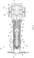
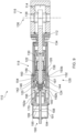
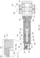
- the actuator 10 comprises an electrically-operable subsea actuator 10 for providing a subsea electrical actuation of a valve 16.
- the actuator 10 comprises a screw assembly 18, here in the form of a roller screw assembly.
- the screw assembly 18 comprises a screw 20 and a threaded part 22.
- the roller screw assembly 18 comprises a roller screw 20 and a roller nut 22.
- the actuator 10 comprises a housing 24 for the roller screw assembly 18; and an axial stop 26 for preventing axial movement relative to the housing 24 of one of the roller screw 20 and the roller nut 22.
- the actuator 10 comprises a primary drive for providing a rotational movement to the roller screw assembly 18 in a normal mode of operation.
- the roller screw assembly 18 converts the rotational movement to an axial movement of a valve member 14 relative to the housing 24.
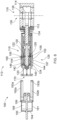
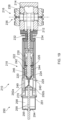
- the actuator 10 comprises an override 28 for operating the actuator 10 in an override 28 mode of operation (as shown in Figures 2 and 4 ).
- the override 28 is configured to release at least one of the roller screw 20 and the roller nut 22 for axial movement relative to the housing 24. In the example shown, the override 28 releases the roller screw 20 for axial movement in the override 28 mode.
- the roller screw 20 of the roller screw assembly 18 here comprises a longitudinal member in the form of a rigid, solid threaded rod.
- the roller nut 22 assembly comprises a plurality of rollers for transmitting drive between the screw 20 and the roller nut 22 of the roller screw assembly 18.
- the transmission converts a rotational motion of the roller screw 20 to a longitudinal motion of the roller nut 22.
- the roles of the roller nut 22 and the roller screw 20 may be reversed, with the transmission converting a rotational motion of the roller nut 22 to a longitudinal motion of the roller screw 20.
- the roller screw assembly 18 is operable by converting rotational movement or torque, such as from a motor (e.g. electric), to axial movement or force.
- the axial movement or force is relative between the roller screw 20 of the roller screw 20 and the transmission. Accordingly, operation of the roller screw 20 provides an axial movement of the roller nut 22 relative to the roller screw 20.
- the axial movement here comprises linear movement (e.g. of the roller nut 22 from right to left, or left to right, as shown in Figures 1 and 2 ).
- the roller screw assembly 18 defines a linear actuator.
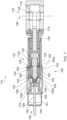
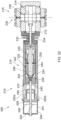
- the actuator 10 comprises a motor, which is the primary drive for operating the actuator 10 in the normal mode of operation, as shown in Figures 1 and 3 .
- the roller screw assembly 18 is operable to selectively axially drive the valve 16 cyclically between open and closed positions.
- the roller screw assembly 18 is operable to push the valve member 14 to an open position (as shown in Figure 1 ) and to pull the valve member 14 to a closed position (similar to the position of the valve member 114 shown in a closed configuration of Figure 6 ).
- the roller screw assembly 18 comprises a push tube 30.
- the valve 16 here has a valve rod or stem 12.
- the valve stem 12 extends through a stem seal 32 housed in a bonnet 34.
- the valve member 14 comprises a bore-sealing member, the bore-sealing member being configured to sealingly occlude access via a bore 36.
- the bore 36 here is for providing access below a XMT (not sown), such as when a XMT is removed, damaged, being inspected or repaired, etc.
- the valve 16 comprises a seat 38 for the bore-sealing member.
- the valve 16 is a gate valve.
- the valve stem 12 is perpendicular to the bore 36, with the valve stem 12 being axially movable along its axis perpendicular to the bore 36. Accordingly, the bore-sealing member 14 is movable transversely into and out of the bore 36 to respectively close and open the bore 36 (e.g. for access via the bore 36).
- At least one of the screw and the roller nut 22 of the roller screw assembly 18 is operatively associated with the valve member 14.
- the roller nut 22 is connected to the valve member 14 such that axial movement of the roller nut 22 axially moves the valve member 14.
- the screw is connected to the valve member 14, such that axial movement of the screw axially moves the valve member 14.
- the roller nut 22 is connected to the push tube 30, the roller nut 22 being the axially movable member of the roller screw assembly 18 in the normal mode of operation (as sown in Figures 1 and 3 ).
- the roller screw 20 is the axially stationary member of the roller screw assembly 18 as shown here, at least during normal or primary operation of the actuator 10.
- the push tube 30 is configured to push the valve stem 12 and also to pull the valve stem 12, with the push tube 30 here being attached to the valve stem 12.
- the actuator 10 comprises a housing 24 configured to maintain an axial position of the axially stationary member of the roller screw assembly 18.
- the housing 24 comprises the axial stop 26 for maintaining the axial position of the roller screw 20, the axial stop 26 preventing axial movement of the axially stationary roller screw in a first axial direction - to the right, towards the valve 16, as shown in Figure 1 .
- a backplate 40 at the rear of the housing 24 prevents axial movement of the roller screw 20 in a second axial direction - to the left, away from the valve 16, as shown in Figure 1 .
- the axial directions are parallel with the longitudinal axis of the roller screw 20.
- the housing 24 limits or prevents axial movement of the roller screw 20 during normal operation of the actuator 10. Accordingly, here, the actuator 10 is normally operable to actively rotate, driven by the motor, the roller screw 20 to axially displace the roller nut 22, thereby axially displacing the valve member 14 associated with the roller nut 22.
- the actuator 10 comprises a bearings assembly 42 comprising a bearings casing 44 containing contact angle bearings 46 for supporting the roller screw 20.
- the bearings 46 provide a high degree of axial stiffness, high axial load carrying capacity; accommodate high speeds and rapid accelerations; and offer high running accuracy.
- the bearings 46 provide a safe radial and axial support and an extremely precise axial guidance of the roller screw 20.
- the housing 24 seals the actuator 10, with an interior of the actuator 10 sealed from an exterior of the actuator 10.
- the housing 24 here comprises a cylinder, with the axial movement of the roller nut 22 being along an axis parallel to a central longitudinal axis of the cylinder.
- the roller screw 20 is electrically operable.
- the roller screw 20 is electrically operable by selectively supplying electrical power to the motor for driving the transmission.
- the electric motor is associated with the screw 20 of the roller screw assembly 18.
- Rotation of the screw 20 e.g. at or towards a first end of the screw
- the screw 20 has a screwthread, with the roller nut 22 comprising an interengaging complementary screwthread profile for engaging the roller screw 20.
- the actuator 10 here is configured to provide an alternative drive to the valve member 14.
- the actuator 10 is configured to move the valve member 14 in an event of a failure of the roller screw assembly 18 or a component thereof, or of the primary drive thereto.
- the actuator 10 is configured to move the valve member 14 in an event of the roller screw assembly 18 becoming stuck.
- the actuator 10 comprises an override 28 configured to allow operation of the valve 16 without requiring transmission of drive from the primary drive (motor) normally used to operate the roller screw 20.
- the override 28 is configured to release the roller screw 20.
- the override 28 is configured to enable movement of the roller screw assembly 18 in unison.
- the override 28 is configured to enable axial movement of the roller screw 20 and the roller nut 22 together.
- the override 28 is configured to allow axial movement of the portion of the roller screw assembly 18 that is normally axially stationary during normal operation of the actuator 10.
- the override allows the roller screw 20 to move axially in the override mode of operation, as shown in Figures 2 and 4 .
- the override 28 comprises a release mechanism 50 configured to allow axial movement of the roller screw 20 that is not otherwise possible without or prior to the operation of the override 28.
- the release mechanism 50 is configured to allow axial movement of the roller screw 20 not normally possible during normal operation of the actuator 10, upon activation of the override 28, as shown in Figures 1-4 .
- the override 28 here comprises a releasable axial stop 26 defining or limiting axial movement in at least one direction for the roller screw 20.
- the axial stop 26 comprises a bearing shoulder. Operation of the override 28 to release the releasable stop allows movement of the stationary member of the roller screw assembly 18 not otherwise possible without or prior to the operation of the override 28.
- the roller screw 20 In normal operation of the actuator 10 the roller screw 20 is axially stationary, with driven rotation of the roller screw 20 consequently driving axial movement of the roller nut 22.
- the actuator override 28 when the actuator override 28 is activated, operation of the actuator 10 in override 28 mode allows axial movement of the roller screw 20. Accordingly, here, the override 28 may allow axial movement of both the roller screw 20 and the roller nut 22, such as in tandem or unison.
- the release mechanism 50 is configured to release the bearing assembly 42 for axial movement, the bearing assembly 42 normally being axially fixed or limited by the axial stop 26 in the form of the bearing shoulder. Accordingly, operation of the override 28 allows axial movement of the bearing assembly 42 jointly with the roller screw 20.
- the override 28 is configured to release the bearings casing 44 for axial movement with the roller screw 20, upon activation of the override 28. As shown in Figures 1 and 3 , the bearings casing is axially stationery during normal operation, being stopped by the axial stop 26.
- the release mechanism 50 releases the roller screw 20 from the bearing assembly 42.
- the release mechanism 50 in such examples is configured to allow the roller screw 20 to move longitudinally relative to the bearing assembly 42 in the override 28 mode.
- the roller screw 20 is axially immovable relative to the bearings assembly during normal operation of the actuator 10.
- the release mechanism 50 here comprises an external release interface, external of the actuator housing 24.
- the release mechanism 50 comprises an external release sleeve 52 located on an exterior of the actuator 10 housing 24. Accordingly, the release mechanism 50 is operated externally of the actuator 10.
- the release mechanism 50 is normally be locked in position, by a mechanical lock, comprising a shear pin 54 here for limiting or preventing movement of the external release sleeve 52 in normal use of the actuator 10.
- the shear pin is disassociated with the roller screw assembly 18, being isolated from forces associated with the roller screw assembly 18.
- forces associated with the roller screw assembly 18 and bearings 46 therefor are isolated from the shear pin 54 by one or more bearings/balls 56 providing an interface between the external release sleeve 52 and the roller screw assembly 18 and bearings 46 therefor.
- the shear pin 54 here is prevented from shearing due to movement or force associated with the normal operation of the roller screw assembly 18.
- the shear pin 54 is only sheared by a movement or force applied externally to the external release sleeve 52.
- the bearings/balls 56 provide for a low axial friction (rolling) for sliding movement during release of the external release sleeve 52, whilst providing a rigid or stiff radial connection between the external release sleeve 52 and the roller screw assembly 18.
- the actuator 10 comprises a retainer 58 associated with the axial stop 26, the retainer 58 retaining the axial stop 26 axially during normal operation of the actuator 10.
- Activation of the release mechanism 50 entails a transverse movement of the retainer 58.
- the retainer 58 comprises a split lock ring.
- the retainer 58 comprises a pretension when assembled in the actuator 10.
- the retainer 58 comprises a transverse, radial, pretension when assembled in the actuator 10. The pretension assists in releasing the retainer 58 from its normal position when the release mechanism 50 is activated.
- the retainer 58 is normally locked in position during normal operation of the actuator 10, with the override 28 releasing the retainer 58.
- the override 28 does not comprise a bypass, such as a bypass for bypassing one or more of the roller screw 20 and/or the roller nut 22.
- the override 28 utilises at least some functionality of the roller screw assembly 18 to operate the valve member 14 in the override mode of operation.
- the override 28 here utilises a same connection of the roller screw assembly 18 to the valve member 14 for operating the valve 16 assembly in the override mode as the connection of the roller screw assembly 18 to the valve member 14 for operating the valve 16 assembly in normal or primary operation prior to operation of the override 28.
- the override 28 allows operation of the same push tube 30 for pushing and pulling the valve member 14 as in normal or primary operation of the actuator 10.
- the override 28 is configured to utilise the interface between the roller screw 20 and the roller nut 22 of the roller screw assembly 18 to directly transmit force and/or movement in a same direction or mode.
- the override 28 allows a transfer of an axial force and/or axial movement between the roller screw 20 and the roller nut 22 (e.g. axially pushing/pulling the roller screw 20 axially pushes/pulls the roller nut 22 via the threaded interface/s therebetween).
- the override 28 is configured to rotate the roller screw 20. Accordingly, the actuator 10 does not comprise or require an additional or alternative connection between the roller screw assembly and the valve member.
- the actuator 10 comprises an external interface 70 for an override tool (not shown) axially external to the actuator 10.
- the override tool interface 70 is provided at or through an axial end of the cylinder.
- the override tool interface 70 is positioned with the roller screw assembly 18 located between the override tool interface 70 and the valve member 14.
- the override tool interface 70 is configured to transmit torque and/or axial force to the roller screw 20 to move the valve member 14.
- the override tool interface 70 comprises a torque interface to allow clockwise and/or counter-clockwise torque to be applied to the roller screw 20 to move the valve member 14.
- the override tool interface 70 is configured to drive the roller screw 20 axially in the first direction to push the valve member 14.
- the override tool interface 70 is configured to drive the roller screw 20 axially in the second direction to pull the valve member 14.
- the override tool interface 70 is configured to drive the roller screw 20 axially to open and close the valve member 14.
- the override tool interface 70 is configured to drive the at least a portion of the roller screw assembly 18 rotationally to open and close the valve member 14.
- the roller screw 20 has been axially and rotationally drive from the position of Figure 1 to the position of Figure 2 , thereby axially moving the roller screw 20 relative to the roller nut 22. It will be appreciated that the roller screw 20 may be driven further (e.g. to the right in Figure 2 ).
- the override tool (not shown, but may be generally similar to that 190 shown in Figure 6 ) comprises an alternative drive, such as a hydraulic drive.
- the override tool is operated remotely, by a ROV.
- the actuator 10 is configured for override operation by a plurality of override tools, such as by a ROV override tool in a first override operation; and operated manually in a second override operation (e.g. if the first override operation was unsuccessful; or if subsequently the first override operation was desired to be reversed).
- the actuator 10 comprises a rotational stop 80 for the roller nut 22 to prevent or at least limit rotation of the roller nut 22, during normal and override operation of the actuator 10. Accordingly, the rotational stop 80 helps provide for the conversion of relative rotation between the roller screw 20 and the roller nut 22 to axial movement.
- the axial movement here is therefore pure, non-rotational linear movement in the axial direction.
- the rotational stop 80 here comprises a plurality of anti-rotation pins associated with the roller nut 22, received in axial guide channels 82 associated with the housing 24.
- the actuator 10 is used as a subsea actuator 10 to provide an axial force to an element.
- the actuator 10 is used to operate one or more valves 16, such as gate valves 16.
- the valve 16 may form part of a XMT, such as a vertical XMT.
- the XMT comprises an Enhanced Vertical Deepwater Tree.
- the actuator 10 is used in an all-electric application, such as an all-electric XMT, Wellhead, SCM or the like.
- the actuator 10 comprises a subsea electrical actuator 10 for providing a subsea electrical actuation.
- the valve 16 comprises a subsea gate valve 16 for selectively providing access via the bore 36 below a XMT.
- the valve 16 is normally closed, such as during normal operation of the XMT.
- the valve 16 is selectively openable by operation of the actuator 10.
- the roller screw assembly 18 comprises a planetary roller screw assembly 18.
- the actuator 10 is configured for high-precision.
- the actuator 10 is configured for high-speed.
- the actuator 10 is configured for heavy-load applications.
- the actuator 10 is configured for long-life applications.
- the actuator 10 is configured for heavy-use applications. It will be appreciated that the actuator 10 for the valve 16 shown here forms part of a subsea wellhead apparatus for controlling access to a hydrocarbon wellbore.
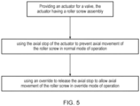
- Figure 5 depicts a method of operation of the actuator 10 of Figures 1 to 4 .
- the method comprises providing the actuator 10 of Figure 1 for subsea actuation of the valve 16.
- the method comprises using the axial stop 26 of the actuator 10 to prevent axial movement of the roller screw 20, the axial movement being relative to the housing 24 for the roller screw assembly 18.
- the method comprises providing the rotational movement to the roller screw assembly 18 in the normal mode of operation with the primary drive (electric motor).
- the method comprises using the roller screw assembly 18 to convert the rotational movement to the axial movement of the valve member 14 relative to the housing 24.
- the method comprises using the override 28 to operate the actuator 10 in the override 28 mode of operation.
- the method comprises releasing the roller screw 20 for axial movement relative to the housing 24.
- the method comprises axially moving the roller screw 20 to move the valve member 14 in the override mode of operation.
- the method comprises releasing the axial stop 26 to release the roller screw 20 for axial movement relative to the housing 24, with the axial stop 26 comprising the shoulder preventing the axial movement of the roller screw 20 in normal operation of the actuator 10.
- the method comprises overriding the electric motor that is used to operate the actuator 10 in the normal mode of operation.
- the method comprises using an alternative drive to operate the actuator 10 in the override 28 mode of operation.
- the method comprises operating the valve 16 of the wellhead apparatus for controlling access to a hydrocarbon wellbore.
- the override 28 may enable operation of the valve 16.
- Figure 6 shows a further embodiment of an actuator 110 generally similar to that shown in Figures 1 to 4 .
- the actuator 110 of Figure 6 shares features common to the embodiment of Figure 1 , with those features represented by reference numerals incremented by 100.
- the actuator 100 comprises a roller screw assembly 118 with a roller screw 120 and a roller nut 122. Not all features common to both embodiments are repeated here to maintain brevity and clarity. Operation of the actuators 10, 110 is generally similar, with override possible by an override tool.
- an example override tool 190 is also depicted in Figure 6 .
- the override tool 190 is configured to engage with the override tool interface 170 at the axial end of the cylinder, as shown in the transition from Figure 6 to Figure 7 .
- the override tool 190 is shown here with a pair of arms 192a, 192b positioned around an exterior of the cylindrical actuator housing 124.
- Each of the override tool arms 192a, 192b comprises an inner protrusion 193a, 193b for engaging the external release sleeve 152 of the actuator 110.
- the override tool has been slid over the housing 120 (towards the right) from the positions of Figure 6 .
- the protrusions 192a, 192b can be positioned beyond the external release sleeve 152 due to flexion of the override tool arms 192a, 192b as the protrusions 193a, 193b ride over the external release sleeve 152.
- the protrusions 193a, 193b may be positioned beyond the external sleeve 152 (to the right as shown in Figure 7 ) by rotating the override tool arms 192a, 192b to align with castellations or gaps in the external release sleeve 152 before rotating to align the protrusions 193a, 193b with corresponding protrusions on the external release sleeve 152.
- the override tool may comprise more or less arms for engaging the external release sleeve 152.
- an override tool may have a sleeve or arms for pushing the external release sleeve, such as the external release sleeve 52 shown in Figure 1 .
- the external release sleeve 152 can be operated - here by pulling on the arms 192a, 192b.
- the arms 192a, 192b can be controlled to operate the sleeve 152 by applying a force such as from a cylinder or piston.
- a force such as from a cylinder or piston.
- pressurisation of a chamber 194 can force movement of a piston 195 to force the arms 192a, 192b to operate the sleeve 152.
- the piston 195 here divides a volume defined by an override tool cylinder 191 into two chambers 194, 198.
- the shear pin 154 is configured to shear at a force exerted by the arms 192a, 192b of the override tool 190 - pulling the release sleeve 152 to the left as shown in Figure 8 to shear the pin 154 (whereas the sleeve 52 can be pushed to the right in the transition between Figures 1 and 2 , and Figures 3 and 4 , to shear the shear pin 54).
- the override tool 190 can be hydraulically operated, such as by supplying or pressurising hydraulic fluid in/into the chamber 194 to move the external release sleeve 152 to shear the shear pin 154.
- shear the shear pin 154 can be used to shear the shear pin 154, such as pressurisation of other chambers (e.g. in some embodiments an inner override tool chamber 196 may be pressurisable) or other actuation means, such as electrically-operated or even manual.
- pressurisation of other chambers e.g. in some embodiments an inner override tool chamber 196 may be pressurisable
- other actuation means such as electrically-operated or even manual.
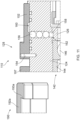
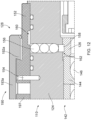
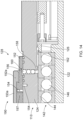
- FIG. 12 through 13 A detailed view of the shearing of the shear pin can be seen in Figures 12 through 13 .
- the external release sleeve 152 comprises a cavity 160 that becomes aligned to release the axial stop 126 as illustrated in Figures 13 through 14 .
- the axial stop 126 can be released, similarly as for the actuator 10 of Figure 4 .
- the cavity 160 is progressed to the axial position of the bearings/balls 156, allowing the bearings/balls to be pushed radially outwards with the retainer 158, thereby releasing the axial stop 126 for axial movement of the roller screw assembly 118 in the override mode as shown in Figure 4 .
- an angle 162 on the axial stop 126 supports transverse release of the retainer 58.
- the angle 162 is configured to assist in transverse movement of the retainer 158 away from the axial stop 126 when the retainer is urged in an axial direction - the axial direction being that of the actuator 110, with the transverse direction here being perpendicular thereto.
- the angle is not a right-angle; here the angle 162 is defined by a face of the axial stop 126 that is inclined rearwards (to the left in Figure 13 ) by a few degrees. Accordingly, the angle 162 is a small acute angle of a few degrees to a radial transverse access of the actuator 110; and defines an obtuse opening of a few degrees more than 90 degrees between a side face (e.g. cylindrical outer side wall) of the axial stop 126.
- the retainer 158 may comprise an offset angle to assist transverse movement of the retainer 158 resultant from an axial force applied (such as by the axial stop 126).
- the bearings/balls 156 With the cavity 160 aligned with the bearings/balls 156, the bearings/balls 156 are freed to move radially outwards into the cavity 160, such as when urged by the retainer 158 - and depicted in the transition from Figure 13 to Figure 14 .
- the retainer 158 when the retainer 158 is urged radially outwards via the angle 162 by an axial force urging the axial stop 126, the retainer 158 is no longer prevented from radial movement by the external release sleeve 152 (via the bearings/balls 156) in the override configuration of Figure 13 and Figure 14 (and Figures 8 through 10 ), contrary to the normal operation configuration of the actuator 110 of Figure 11 (and Figure 7 ). Accordingly, the retainer 158 can be released by the override tool 190, freeing the axial stop 126, thus allowing axial movement of the roller screw assembly 118 as shown in Figures 9 , 10 and 13 .
- the axial stop 126 and/or the retainer 158 can be circumferential (e.g. rings here). Although only a single set of bearings/balls 156 is shown in the cross-section in the figures, it will be appreciated that multiple sets (e.g. three) may be spaced circumferentially around the actuator 110.
- the piston 195 is connected to a tool stem 199 that is connected to and engages the actuator override tool interface 170. Accordingly, as shown in Figure 9 , axial movement of the piston 195 causes axial movement of the tool stem 199, here a stem rod, and actuation of the actuator 110 via the actuator override tool interface 170, as described in detail below.
- the roller screw assembly 118 is no longer prevented from axial movement as a unit.
- the bearing assembly 142 including the bearing casing 144, is freed for axial movement by the actuation of the external release sleeve 152.
- the application of force from the actuator tool 190 here via the override tool interface 170 and the tool stem 199 driven by the piston 195, drives the entire roller screw assembly 118, including the bearing assembly 142, axially. Accordingly, even in an event of failure of the roller screw assembly 118 or component thereof, the override tool 190 can be utilised to operate the valve member 114.
- the valve member 114 can be operated between the closed position (e.g.
- the override tool 190 may engage the override tool interface 170 to apply torque to the override tool interface 170. Accordingly, in at least some examples, the override tool 190 may be used to rotate the roller screw assembly 118, or a component thereof (such as the roller screw). Such rotation may be used to axially move at least a component of the roller screw assembly 118, or assist therein.
- Figure 15 shows a further embodiment of an actuator 210 generally similar to that 110 shown in Figures 6 to 14 .
- the actuator 210 of Figure 6 shares features common to the embodiment 110 of Figure 6 , with those features represented by reference numerals incremented by 100.
- the actuator 200 comprises a roller screw assembly 218 with a roller screw 220 and a roller nut 222. Not all features common to both embodiments are repeated here to maintain brevity and clarity. Operation of the actuators 110, 210 is generally similar, with override possible by an override tool.
- the example 210 shown here does not comprise an external release sleeve, in contrast to that 152 of Figure 6 .
- the actuator 210 here is configured for release of the bearings assembly 210 by releasing an axial stop, here the backplate 240.
- the method of override involves the release of the roller screw assembly 218 by releasing the bearing assembly 242.
- the backplate 240 has a predefined weakness in the form of an undercut 241, as shown in detail in Figure 15a .
- the undercut 241 extends around the entire circumference of the backplate 240 in the example shown; although in other examples partial undercuts, or multiple discrete undercuts may be used.
- the undercut is supported - here with a pair of half-rings 243 extending around in the annular space provided by the undercut 241.
- the backplate 240 here has a guide groove 245.
- the guide groove 245 assists in positioning a release tool 247, shown here as a core bit.
- an inner wall 249 of the ROV bucket also assists in guiding and supporting the release tool 247.
- the release tool 247 can be used to free the bearings assembly 242 by releasing the backplate 240 - shown in Figure 16 by rotating the core bit of the release tool 247 to cut into the backplate 240, guided by the guide groove 245.
- the bearing assembly 242 has a bearings sleeve 244 configured to transfer loads and keep the bearings 246 pre-loaded.
- the core bit of the release tool 247 only needs to penetrate the backplate 240 to the undercut 241.
- the undercut 241 may extend into a smaller diameter - such as to allow for additional tolerance in the positioning and/or cutting of the core bit of the release tool 247.
- the actuator 210 is in a generally similar configuration to that shown in Figures 2 and 8 - with the roller screw assembly 218 able to move axially as a unit together with the bearing assembly 242.
- the roller screw assembly 218 is no longer prevented from axial movement as a unit.
- the bearing assembly 242, including the bearing sleeve 244 is freed for axial movement by the cutting of the backplate 240.
- an override tool 290 can be used to engage the external interface 270 of the actuator 210 to control the valve 216 with the actuator 210.
- pressurisation of the chamber 294 causes the piston 295 connected to the tool stem 299 to move relative to the override tool cylinder housing 291.
- axial movement of the piston 295 causes axial movement of the tool stem 299, here a stem rod, and actuation of the actuator 210 via the actuator override tool interface 270.
- the valve member 214 can be operated between the closed position (e.g. Figure 16 ) and the open configuration (e.g. Figure 22 ). It will be appreciated that the embodiment shown in Figures 18 to 22 has the roller screw assembly 218 being pushed in unison as a single unit to move the valve member 214 to the open position.
- the override tool 290 can engage the override tool interface 270 to grip the override tool interface 270, such that the roller screw assembly 218 can also be pulled (e.g. to close the valve 216 by pulling the valve member 214 from the position of Figure 22 to the position of Figure 16 ).
- the longitudinal member of the roller screw assembly may comprise an interface or profile for interengagement (e.g. screwthread/s, spline/s) at only one or more portions of the longitudinal member (e.g. one or more axial zones).
Landscapes
- Life Sciences & Earth Sciences (AREA)
- Engineering & Computer Science (AREA)
- Geology (AREA)
- Mining & Mineral Resources (AREA)
- Physics & Mathematics (AREA)
- Environmental & Geological Engineering (AREA)
- Fluid Mechanics (AREA)
- General Life Sciences & Earth Sciences (AREA)
- Geochemistry & Mineralogy (AREA)
- Transmission Devices (AREA)
- Mechanically-Actuated Valves (AREA)
Description
- This disclosure concerns an actuator, such as a subsea actuator for actuating a subsea valve; and associated methods, such as methods of actuating and/or overriding valves.
- In the oil/gas industry, wellheads are typically at least partly controlled using Subsea Control Modules ("SCMs"), such as where an SCM controls a Xmas Tree ("XMT") associated with a production wellhead. The SCM provides well control functions, particularly during the production phase of subsea oil/gas production. The SCM contains electronics for performing a variety of functions, often including: processing communications signals, conditioning electrical power supplies, providing status information; and distributing signals and power to/from control valves, pressure/temperature sensors, and the like.
- XMTs typically have various fluid barriers for controlling fluid, pressure, flow in the well. Periodically XMTs may require maintenance, inspection, etc. Often temporary barriers are placed using bores below the XMT. These bores are typically dedicated for such temporary use and access via these bores is only enabled when particular valves are open to allow such access. The valves are typically gate valves operable between a closed position, where the bore (below the XMT) is closed.
-
EP2165100 discloses a valve actuator comprising a screw member coupled to a valve stem and a sleeve such that rotation of the sleeve causes translation of the valve stem. The sleeve has a first end that is rotatably coupled to a housing that is fixably coupled to a valve body and a second end that projects out of the housing. The valve stem is partially disposed within the sleeve and extends into the valve body. A transmission is coupled to the housing and engaged with the sleeve. A motor is coupled to the transmission so that operation of the motor causes rotation of the sleeve. -
WO 2019/141595 relates to a subsea electric actuator operating a linear valve, the actuator comprising a roller-screw for translating a rotational movement of a motor to a linear movement of a gate rod operating the valve. - The subject matter of at least some examples of the present disclosure may be directed to overcoming, or at least reducing the effects of, one or more of the problems of the prior art, such as may be described above.
- According to a first aspect there is provided an actuator as defined in the appended claims. The actuator comprises an electrically-operable actuator. The actuator may be for operating a valve. The actuator comprises a subsea actuator, such as a subsea electrical actuator for providing a subsea electrical actuation of the valve. The actuator comprises a screw assembly. The screw assembly comprises a roller screw. The screw assembly comprises a threaded part, such as a female threaded part (e.g. a nut), for receiving the screw. The screw assembly comprises a roller screw assembly. The roller screw assembly comprises a roller screw and a roller nut. The actuator comprises a housing for the screw assembly. The actuator comprises an axial stop for preventing axial movement relative to the housing of one of the screw and the threaded part. The actuator comprises a primary drive for providing a rotational movement to the screw assembly in a normal mode of operation. The screw assembly is for converting the rotational movement to an axial movement of a valve member relative to the housing. The actuator comprises an override for operating the actuator in an override mode of operation. The override is configured to release at least one of the screw and the threaded part for axial movement relative to the housing. The actuator may be configured to be overridden by release of at least a portion of the screw assembly. The portion for release in override may be otherwise fixed or restrained in normal operation of the actuator. The actuator may be configured for override by release of the entire screw assembly, such as release of the screw assembly relative to a housing of the actuator.
- The screw assembly may comprise a longitudinal member for axial movement along a central axis of the longitudinal member. The longitudinal member may comprise the screw of the screw assembly. The screw of the screw assembly may be a spindle. The longitudinal member may comprise a solid member. The longitudinal member may comprise a rigid, solid rod. The screw assembly may comprise a transmission for transferring drive to or from the longitudinal member. A threaded part assembly, such as a roller nut assembly, may comprise the transmission. The roller nut assembly may comprise a plurality of rollers for transmitting drive between the screw and the roller nut of the roller screw assembly. The transmission may convert a rotational motion of the screw to a longitudinal motion of the threaded part. Alternatively the transmission may convert a rotational motion of the threaded part to a longitudinal motion of the screw.
- The screw assembly may be operable by converting rotational movement or torque, such as from a motor (e.g. electric), to axial movement or force. The axial movement or force may be relative between the longitudinal member of the screw and the transmission. For example operation of the screw may provide an axial movement of the threaded part relative to the screw. The axial movement may comprise linear movement. The screw assembly may define a linear actuator. The actuator may comprise the motor. The motor may comprise the primary drive for operating the actuator in the normal mode of operation.
- The screw assembly may be operable to axially drive the valve between positions. The screw assembly may be operable to selectively drive the valve cyclically between open and closed positions. For example, the screw assembly may be operable to push a valve member to an open position and to pull the valve member to a closed position. The screw assembly may comprise a push member. The push member may comprise a push rod. The push rod may comprise a hollow push rod. Accordingly, the push member may comprise a push tube.
- The valve may comprise a valve member, such as a valve rod or stem. The valve stem may extend through a stem seal. In at least some examples, the valve assembly may comprise a bonnet, the bonnet housing the stem seal through which the valve stem may extend. The valve may comprise a bore-sealing member, the bore-sealing member being configured to sealingly occlude access via a bore. The bore may be for providing access below a XMT, such as when a XMT is removed, damaged, being inspected or repaired, etc. The valve may comprise a seat for the bore-sealing member. The bore-sealing member may comprise a gate. The valve stem may be perpendicular to the bore, with the valve stem being axially movable along its axis perpendicular to the bore. Accordingly, the bore-sealing member may be movable transversely into and out of the bore to respectively close and open the bore (e.g. for access via the bore).
- At least one of the screw and the threaded part of the screw assembly may be operatively associated with the valve member. For example, the threaded part may be connected to the valve member such that axial movement of the threaded part axially moves the valve member. In other examples, the screw may be connected to the valve member, such that axial movement of the screw axially moves the valve member. The screw or the threaded part may be connected to the push member. The portion of the screw assembly connected to the valve member (e.g. via the push member) may be an axially movable member of the screw assembly. The other portion of the screw assembly may be an axially stationary member of the screw assembly, at least during normal or primary operation of the actuator. For example, the threaded part may be the axially movable member and the screw may be the axially stationary member (or vice versa). The push member may be configured to push the valve stem. The push member may be configured to pull the valve stem. The push member may be attached to the valve stem.
- The actuator may comprise a housing. The housing may be configured to maintain an axial position of the axially stationary member of the screw assembly. For example, the housing may comprise an axial stop for maintaining the axial position of the screw. The axial stop may prevent axial movement of the axially stationary member in a first and/or a second axial direction. In at least some examples, the housing may prevent axial movement in both axial directions. The axial directions may be parallel with the longitudinal axis of the screw. The housing may limit or prevent movement of the axially stationary member during normal operation of the actuator. Accordingly, in at least some examples, the actuator may be normally operable to actively rotate, such as driven by the motor, the screw to axially displace the threaded part, thereby axially displacing the valve member associated with the threaded part.
- The actuator may comprise a bearings assembly comprising a bearings casing containing bearings. The bearings may support at least a portion of the screw assembly. For example, the bearings may support the screw. The bearings may comprise contact angle bearings. The bearings may provide a high degree of axial stiffness. The bearings may provide a high axial load carrying capacity. The bearings may provide accommodate high speeds and rapid accelerations; and offer high running accuracy. The bearings may provide a safe radial and axial support. The bearings may provide an extremely precise axial guidance of the longitudinal member (e.g. the screw).
- The bearings assembly may comprise a bearing sleeve. The bearing sleeve may be configured to transfer loads. The bearings sleeve may be configured to keep the bearings pre-loaded.
- In at least some examples, the housing may at least partially seal the actuator. For example, the housing may seal an interior of the actuator from an exterior of the actuator. The housing may comprise a cylinder, with the axial movement being along an axis parallel to a central longitudinal axis of the cylinder.
- The screw may be electrically operable. The screw may be electrically operable by selectively supplying electrical power to a motor for driving the transmission. For example, an electric motor may be associated with the screw of the screw assembly. Rotation of the screw (e.g. at or towards a first end of the screw) may force the threaded part to move axially, parallel to a central longitudinal axis of the screw. The screw may comprise a spline, such as a screwthread. The threaded part may comprise an interface/s for engaging the screw, such as an interengaging complementary profile. The threaded part may comprise a screwthread/s for engaging the screw. The threaded part may comprise a threaded part assembly.
- The actuator may be configured to provide an alternative drive to the valve member. The actuator may be configured to move the valve member in an event of a failure of the screw assembly or a component thereof, or of the primary drive thereto. The actuator may be configured to move the valve member in an event of the screw assembly becoming stuck.
- The actuator may comprise an override. The override may be configured to allow operation of the valve without requiring transmission of drive from the primary drive. The primary drive may comprise the drive normally used to operate the screw. The override may be configured to release at least one of the screw and the threaded part of the screw assembly. In at least some examples, the override may be configured to enable movement of the screw assembly in unison. The override may be configured to enable movement of the screw assembly as a single unit. For example, the override may be configured to enable axial movement of the screw and the threaded part together. The override may be configured to move, such as translate, the entire screw assembly. The override may be configured to move the screw assembly without causing or requiring relative movement between the screw and the threaded part. The override may be configured to allow axial movement of the portion of the screw assembly that is normally axially stationary during normal operation of the actuator. For example, where the screw is normally stationary, the override may be configured to allow axial movement of the screw during the override mode of operation.
- In at least some examples, the override comprises a release mechanism. The release mechanism may be configured to allow a movement of at least one of the screw and/or the threaded part. The movement may comprise an axial movement. The movement may comprise a movement not otherwise possible without or prior to the operation of the override. The release mechanism may be configured to allow axial movement of the axially stationary member, upon activation of the override. For example, activation of the override, operating the release mechanism, may allow axial movement of the screw not normally possible during normal operation of the actuator.
- The override may comprise a releasable stop. The releasable stop may comprise an axial stop defining or limiting axial movement in at least one direction for at least one of the screw and/or threaded part. The releasable stop may define or limit an axial position of the axially stationary member. The axial stop may comprise a shoulder. The axial stop may comprise a bearing shoulder. Operation of the override to release the releasable stop may allow movement of the stationary member of the screw assembly not otherwise possible without or prior to the operation of the override. For example, in normal operation of the actuator the screw may be axially stationary, with driven rotation of the screw consequently driving axial movement of the threaded part. When the actuator override is activated, operation of the actuator in override mode may allow axial movement of the screw. Accordingly, in at least some examples, the override may allow axial movement of both the screw and the threaded part, such as in tandem or unison.
- In at least some examples, the releasable stop may comprise a backplate, or at least a portion thereof. The method of override may comprise a release of at least a portion of the backplate. The portion of the backplate may be connected to or associated with the portion of the screw assembly. The release mechanism may comprise a weakness, such as a predefined weakness. The actuator may be reconfigurable from a normal mode of operation to an override mode of operation upon activation or rupturing of the predefined weakness.
- The release mechanism may be configured to release the bearing assembly for axial movement. The bearing assembly may normally be axially fixed or limited, such as by the axial stop. Accordingly, operation of the override may allow axial movement of the bearing assembly, such as jointly with the longitudinal member. In at least some examples, the override is configured to release the bearings casing for axial movement. Accordingly, the bearings casing may be axially movable, such as with the screw, upon activation of the override. The bearings casing may be axially stationery during normal operation, such as being stopped by the axial stop.
- The release mechanism may be configured to release the longitudinal member from the bearing assembly. For example, the release mechanism may be configured to allow the longitudinal member to move longitudinally relative to the bearing assembly in the override mode. The longitudinal member may be axially immovable relative to the bearings assembly during normal operation of the actuator.
- The release mechanism may comprise an external release interface. The external release interface may be external of the actuator housing, such as a cylinder containing the actuator. The release mechanism may comprise a release member. The release mechanism may comprise an external release member. The external release member may comprise an external sleeve, such as located on an exterior of the actuator housing. Accordingly, the release mechanism may be operated externally of the actuator. The release mechanism may normally be locked in position, such as by a mechanical lock. In at least some examples, the mechanical lock comprises a shear pin. The mechanical lock may be for limiting or preventing movement of the release member, such as in normal use of the actuator. The shear pin may be disassociated with the screw assembly. The shear pin may be isolated from forces associated with the screw assembly. For example, forces associated with the screw assembly or bearings therefore may be isolated from the shear pin. Accordingly, the shear pin may be prevented from shearing due to movement or force associated with the normal operation of the screw assembly. The shear pin may be sheared by a movement or force applied to an external portion of the actuator. For example, the shear pin may be, optionally may only be, sheared by a force applied externally to the release member.
- Different examples may comprise different release mechanisms. In at least some examples, reconfiguration of the actuator from the normal mode of operation to the override mode of operation may comprise an irreversible process, or at least only reversible by a resetting and/or retrieval of at least a portion of the actuator. For example, the actuator may be reconfigurable to the override mode of operation by activation or rupturing of the predefined weakness. The predefined weakness may comprise a shear pin, rupture disc and/or a portion of another member, such as a predefined thinning or narrowing (e.g. of a portion of the backplate). In other examples, the reconfiguration of the actuator from the normal mode of operation to the override mode of operation may be reversible.
- The actuator may be configured for bidirectional operation by the override tool. The actuator may be configured to activate and/or deactivate by the override tool. For example, the actutator may be configured to both open and close the valve with the override tool.
- The actuator may comprise a retainer. The retainer may comprise or be associated with the axial stop. In at least some examples, the retainer retains the axial stop axially during normal operation of the actuator. Activation of the release mechanism may comprise a transverse movement of the axial stop or a member associated therewith. The transverse movement may be of the retainer. The retainer may comprise a ring, such as a lock ring. The lock ring may comprise a split lock ring. The retainer may comprise a pretension when assembled in the actuator. For example, the retainer may comprise a transverse, such as radial, pretension when assembled in the actuator. The pretension may assist in maintaining the retainer in its normal retaining position during normal operation of the actuator. Alternatively, the pretension may assist in releasing the retainer from its normal position when the release mechanism is activated. The retainer may normally be locked in position during normal operation of the actuator. The override may release the retainer.
- The release mechanism may be configured to release the bearing assembly for axial movement. The bearing assembly may normally be axially fixed or limited, such as by the axial stop. Accordingly, operation of the override may allow axial movement of the bearing assembly, such as jointly with the longitudinal member. In at least some examples, the override is configured to release the bearings casing for axial movement. Accordingly, the bearings casing may be axially movable, such as with the screw, upon activation of the override. The bearings casing may be axially stationery during normal operation, such as being stopped by the axial stop.
- The override may not comprise a bypass, such as a bypass for bypassing one or more of the screw and/or the threaded part. In at least some examples, the override utilises at least some functionality of the screw assembly to operate the valve member. The override may utilise a same connection of the screw assembly to the valve member for operating the valve assembly in override mode as the connection of the screw assembly to the valve member for operating the valve assembly in normal or primary operation, such without or prior to operation of the override. The override may allow operation of the same push member for pushing and/or pulling the valve member as in normal or primary operation of the actuator. The override may be configured to utilise the interface between the screw and the threaded part of the screw assembly. The override may be configured to utilise the interface between the screw and the threaded part of the screw assembly to directly transmit force and/or movement in a same direction or mode. For example, the override may allow a transfer of an axial force and/or axial movement between the screw and the threaded part (e.g. axially pushing/pulling the screw may axially push/pull the threaded part via the spline interface/s therebetween). Additionally, or alternatively, the override may be configured to rotate the screw and/or the threaded part. Accordingly, the actuator may not comprise or require an additional or alternative connection.
- The actuator may comprise an interface for an override tool. The override tool interface may comprise an external interface. The external interface may be axially external to the actuator. For example, where the actuator housing comprises a cylinder, the override tool interface may be provided at or through an axial end of the cylinder. The override tool interface may be positioned with the screw assembly located between the override tool interface and the valve member. The override tool interface may be configured to transmit torque and/or axial force to at least a portion of the screw assembly to move the valve member. The override tool interface may comprise a torque interface to allow clockwise and/or counter-clockwise torque to be applied to at least a portion of the screw assembly to move the valve member. The override tool interface may be configured to drive the at least a portion of the screw assembly axially in a first direction to push the valve member. Additionally, or alternatively, the override tool interface may be configured to drive the at least a portion of the screw assembly axially in a second direction to pull the valve member. The override tool interface may be configured to drive the at least a portion of the screw assembly axially to open the valve member. Additionally, or alternatively, the override tool interface may be configured to drive the at least a portion of the screw assembly rotationally to open the valve member.
- The override tool may comprise an alternative drive. The alternative drive may comprise an electric drive, such as an alternative electric motor. Additionally or alternatively, the alternative drive may comprise a hydraulic drive.
- The override tool may be operated remotely. The override tool may comprise or may be operated by a ROV. Additionally, or alternatively, the override tool may be operated manually. In at least some examples the actuator may be configured for override operation by a plurality of override tools. For example, the actuator may be configured to be operated by a ROV override tool in a first override operation; and operated manually in a second override operation (e.g. if the first override operation was unsuccessful; or if subsequently the first override operation was desired to be reversed).
- The actuator may comprise a rotational stop for at least one of the screw and the threaded part. The rotational stop may prevent or at least limit rotation of the axially-movable member, at least during normal operation of the actuator. Accordingly, the rotational stop may provide for conversion of relative rotation between the screw and the threaded part to axial movement. The axial movement may therefore may be pure, non-rotational linear movement in the axial direction. The rotational stop may comprise at least one anti-rotation pin. The actuator may comprise a guide member for guiding axial movement of the threaded part and/or the screw. For example, the guide member may comprise a pin in an axial channel. The axial channel may be provided in or associated with the housing; and the guide pin provided in or associated with the threaded part. Alternatively, the axial channel may be provided in or associated with the threaded part
- The actuator may comprise an underwater or subsea actuator. The actuator may comprise a subsea electrical actuator for providing a subsea electrical actuation.
- The valve may comprise a subsea valve. The valve may comprise a linear valve, such as a gate valve. The valve may be for selectively providing access via a bore below a XMT. The valve may be normally closed, such as during normal operation of the XMT. The valve may be selectively openable by operation of the actuator.
- The screw assembly may comprise a planetary screw assembly, such as a planetary roller screw assembly. The screw assembly may comprise a non-recirculating screw assembly. The lack of axial movement of the screw may not move axially relative to the threaded part. The screw assembly may comprise an inverted screw assembly, such as an inverted roller screw assembly. The screw assembly may comprise a reverse screw assembly, such as a reverse roller screw assembly.
- The screw may comprise a recirculating screw, such as a recirculating roller screw. The rollers may move axially within the nut. The rollers may be reset, such as after one orbit about the screw.
- The actuator may be configured for high-precision. The actuator may be configured for high-speed. The actuator may be configured for heavy-load applications. The actuator may be configured for long-life applications. The actuator may be configured for heavy-use applications.
- In at least some examples, the actuator is used as a subsea actuator to provide an axial force to an element. The actuator may be used to operate one or more valves, such as a gate valve/s. The valve may form part of a XMT, such as a vertical XMT. The XMT may comprise an Enhanced Vertical Deepwater Tree. The actuator may be used in an all-electric application, such as an all-electric XMT, Wellhead, SCM or the like.
- According to a further aspect, there is provided an apparatus comprising the actuator of any other aspect, example, embodiment or claim. The apparatus may comprise a subsea apparatus for the oil/gas industry. The apparatus may comprise a wellhead apparatus for controlling access to a hydrocarbon wellbore. The apparatus may comprise a subsea valve. The apparatus may comprise a subsea control module ("SCM"). The apparatus may comprise a subsea electronics module ("SEM").
- According to a further aspect, there is provided a method of actuation. The method may comprise providing the actuator of any other example, embodiment, claim or aspect. The method may comprise a method of subsea or underwater actuation. The method may comprise providing the actuation in the apparatus of any other aspect, example, embodiment or claim.
- The method may comprise providing a subsea electrical actuator for actuating a valve, the actuator comprising a screw assembly comprising a screw and a threaded part. The screw may comprises a roller screw and the threaded part may comprise a nut. The method may comprise using an axial stop of the actuator to prevent axial movement of one of the screw and the threaded part, the axial movement being relative to a housing for the screw assembly. The method may comprise providing a rotational movement to the screw assembly in a normal mode of operation with a primary drive. The method may comprise using the screw assembly to convert the rotational movement to an axial movement of a valve member relative to the housing. The method may comprise using an override to operate the actuator in an override mode of operation. The method may comprise releasing at least one of the screw and the threaded part for axial movement relative to the housing. The method may comprise axially moving at least one of the screw and the threaded part to move the valve member. The method may comprise axially moving the screw assembly as in unison, as a single unit, to move the valve member.
- The method may comprise releasing the axial stop to release at least one of the screw and the threaded part for axial movement relative to the housing, with the axial stop comprising a shoulder preventing the axial movement of at least one of the screw and the threaded part in normal operation of the actuator. The method may comprise overriding an electric motor that is used to operate the actuator in the normal mode of operation. The method may comprise using an alternative drive to operate the actuator in the override mode of operation.
- The method may comprise operating a valve of a wellhead apparatus for controlling access to a hydrocarbon wellbore.
- According to a further aspect there is provided an apparatus designed and/or manufactured according to the method of any other aspect, example, embodiment or claim.
- According to a further aspect there are provided at least some examples of an oil/gas apparatus comprising the apparatus of any other aspect, example, embodiment or claim. The oil/gas apparatus may comprise wellhead apparatus, such as a manifold.
- Another aspect of the present disclosure provides a computer program comprising instructions arranged, when executed, to implement a method in accordance with any other aspect, example, claim or embodiment. A further aspect provides machine-readable storage storing such a program. The storage may be non-transitory. In at least some examples, the computer program may be for controlling the actuator and/or the override thereof.
- According to an aspect of the invention, there is provided computer software which, when executed by a processing means, is arranged to perform a method according to any other aspect, example, claim or embodiment. The computer software may be stored on a computer readable medium. The computer software may be tangibly stored on a computer readable medium. The computer readable medium may be non-transitory. For example, the computer software may be configured to control the actuator and/or the override thereof.
- The invention includes one or more corresponding aspects, embodiments or features in isolation or in various combinations whether or not specifically stated (including claimed) in that combination or in isolation. For example, it will readily be appreciated that features recited as optional with respect to the first aspect may be additionally applicable with respect to the other aspects without the need to explicitly and unnecessarily list those various combinations and permutations here (e.g. the apparatus of one aspect may comprise features of any other aspect). Optional features as recited in respect of a method may be additionally applicable to an apparatus or device; and vice versa. The apparatus or device of one aspect, example, embodiment or claim may be configured to perform a feature of a method of any aspect, example, embodiment or claim. In addition, corresponding means for performing one or more of the discussed functions are also within the present disclosure. It will also be appreciated that features associated with one of the screw and the threaded part may also be associated with the other of the screw and the threaded part. For example, where examples or features are disclosed in combination with the screw it will be appreciated that those features may apply equally to the threaded part, and vice versa. In at least some examples, the roles of the screw and the threaded part may be inverted (e.g. the threaded part may be axially stationery and the screw axially movable, in normal operation, to axially move the valve member with the screw).
- It will be appreciated that one or more embodiments/aspects may be useful in at least providing a subsea actuation.
- The above summary is intended to be merely exemplary and non-limiting.
- Various respective aspects and features of the present disclosure are defined in the appended claims.
- It may be an aim of certain embodiments of the present disclosure to solve, mitigate or obviate, at least partly, at least one of the problems and/or disadvantages associated with the prior art. Certain embodiments or examples may aim to provide at least one of the advantages described herein.
- These and other aspects of the present invention will now be described, by way of example only, with reference to the accompanying drawings, in which:
-
Figure 1 is a schematic cross-sectional diagram of an assembled subsea actuator and associated valve in a normal mode of operation; -
Figure 2 shows theFig. 1 subsea actuator in an override mode of operation; -
Figure 3 shows a detailed view of a portion of the actuator ofFigure 1 ; -
Figure 4 shows a detailed view of a portion of the actuator ofFigure 2 ; -
Figure 5 is a flowchart showing a method of operating the actuator ofFigure 1 ; -
Figure 6 .is a subsea actuator generally similar to that shown inFigure 1 , in a normal mode of operation, also showing an override tool spaced from the actuator; -
Figure 7 shows the actuator ofFigure 6 showing the override tool in a first engaged position; -
Figure 8 shows the actuator ofFigure 6 with the override tool having sheared a shear pin of the actuator; -
Figure 9 shows the actuator ofFigure 6 , with the override tool having partially moved a valve member associated with the actuator; -
Figure 10 shows the actuator ofFigure 6 , with the override tool having fully moved the valve member, from a closed position ofFigure 6 to an open position ofFigure 10 ; -
Figure 11 shows a detail view of the configuration of the actuator and override tool ofFigure 6 ; -
Figure 12 shows a detail view of the configuration of the actuator and override tool ofFigure 7 ; -
Figure 13 shows a detail view of the configuration of the actuator and override tool ofFigure 8 ; -
Figure 14 shows a detail view of the configuration of the actuator and override tool ofFigure 9 ; -
Figure 15 .is a subsea actuator generally similar to that shown inFigure 6 , in a normal mode of operation, also showing a release tool spaced from the actuator; -
Figure 15a is a detail view of a portion ofFigure 15 ; -
Figure 16 shows the actuator ofFigure 15 with the release tool moved into a first engaging position; -
Figure 16a shows a corresponding detail view ofFigure 16 ; -
Figure 17 shows the actuator ofFigure 15 after operation of the release tool; -
Figure 18 shows the actuator ofFigure 17 , also showing an override tool spaced from the actuator; -
Figure 19 shows the actuator ofFigure 18 , with the override tool engaged with the actuator in a first position; -
Figure 20 shows the actuator ofFigure 10 , with a stem of the override tool advanced to engage an interface of the actuator; -
Figure 21 shows the actuator ofFigure 21 with the actuator being operated by the override tool to open a valve; and -
Figure 22 shows the actuator ofFigure 21 , with the valve operated by the override tool, via the actuator, to the fully open position. - Referring first to
Figure 1 , there is shown anactuator 10 according to the present disclosure. Here, theactuator 10 comprises an electrically-operablesubsea actuator 10 for providing a subsea electrical actuation of avalve 16. Theactuator 10 comprises ascrew assembly 18, here in the form of a roller screw assembly. Thescrew assembly 18 comprises ascrew 20 and a threadedpart 22. Here, theroller screw assembly 18 comprises aroller screw 20 and aroller nut 22. Theactuator 10 comprises ahousing 24 for theroller screw assembly 18; and anaxial stop 26 for preventing axial movement relative to thehousing 24 of one of theroller screw 20 and theroller nut 22. Theactuator 10 comprises a primary drive for providing a rotational movement to theroller screw assembly 18 in a normal mode of operation. Theroller screw assembly 18 converts the rotational movement to an axial movement of avalve member 14 relative to thehousing 24. Theactuator 10 comprises anoverride 28 for operating theactuator 10 in anoverride 28 mode of operation (as shown inFigures 2 and4 ). Theoverride 28 is configured to release at least one of theroller screw 20 and theroller nut 22 for axial movement relative to thehousing 24. In the example shown, theoverride 28 releases theroller screw 20 for axial movement in theoverride 28 mode. - The
roller screw 20 of theroller screw assembly 18 here comprises a longitudinal member in the form of a rigid, solid threaded rod. Theroller nut 22 assembly comprises a plurality of rollers for transmitting drive between thescrew 20 and theroller nut 22 of theroller screw assembly 18. The transmission converts a rotational motion of theroller screw 20 to a longitudinal motion of theroller nut 22. In other examples (not shown) the roles of theroller nut 22 and theroller screw 20 may be reversed, with the transmission converting a rotational motion of theroller nut 22 to a longitudinal motion of theroller screw 20. - The
roller screw assembly 18 is operable by converting rotational movement or torque, such as from a motor (e.g. electric), to axial movement or force. The axial movement or force is relative between theroller screw 20 of theroller screw 20 and the transmission. Accordingly, operation of theroller screw 20 provides an axial movement of theroller nut 22 relative to theroller screw 20. The axial movement here comprises linear movement (e.g. of theroller nut 22 from right to left, or left to right, as shown inFigures 1 and2 ). Here, theroller screw assembly 18 defines a linear actuator. Theactuator 10 comprises a motor, which is the primary drive for operating theactuator 10 in the normal mode of operation, as shown inFigures 1 and3 . - The
roller screw assembly 18 is operable to selectively axially drive thevalve 16 cyclically between open and closed positions. For example, theroller screw assembly 18 is operable to push thevalve member 14 to an open position (as shown inFigure 1 ) and to pull thevalve member 14 to a closed position (similar to the position of thevalve member 114 shown in a closed configuration ofFigure 6 ). Theroller screw assembly 18 comprises apush tube 30. - The
valve 16 here has a valve rod orstem 12. The valve stem 12 extends through astem seal 32 housed in abonnet 34. Thevalve member 14 comprises a bore-sealing member, the bore-sealing member being configured to sealingly occlude access via abore 36. Thebore 36 here is for providing access below a XMT (not sown), such as when a XMT is removed, damaged, being inspected or repaired, etc. Thevalve 16 comprises aseat 38 for the bore-sealing member. As shown here, thevalve 16 is a gate valve. The valve stem 12 is perpendicular to thebore 36, with thevalve stem 12 being axially movable along its axis perpendicular to thebore 36. Accordingly, the bore-sealingmember 14 is movable transversely into and out of thebore 36 to respectively close and open the bore 36 (e.g. for access via the bore 36). - At least one of the screw and the
roller nut 22 of theroller screw assembly 18 is operatively associated with thevalve member 14. Here, theroller nut 22 is connected to thevalve member 14 such that axial movement of theroller nut 22 axially moves thevalve member 14. In other examples (not shown), the screw is connected to thevalve member 14, such that axial movement of the screw axially moves thevalve member 14. Theroller nut 22 is connected to thepush tube 30, theroller nut 22 being the axially movable member of theroller screw assembly 18 in the normal mode of operation (as sown inFigures 1 and3 ). Theroller screw 20 is the axially stationary member of theroller screw assembly 18 as shown here, at least during normal or primary operation of theactuator 10. Thepush tube 30 is configured to push thevalve stem 12 and also to pull thevalve stem 12, with thepush tube 30 here being attached to thevalve stem 12. - The
actuator 10 comprises ahousing 24 configured to maintain an axial position of the axially stationary member of theroller screw assembly 18. Here, thehousing 24 comprises theaxial stop 26 for maintaining the axial position of theroller screw 20, theaxial stop 26 preventing axial movement of the axially stationary roller screw in a first axial direction - to the right, towards thevalve 16, as shown inFigure 1 . Here, abackplate 40 at the rear of thehousing 24 prevents axial movement of theroller screw 20 in a second axial direction - to the left, away from thevalve 16, as shown inFigure 1 . The axial directions are parallel with the longitudinal axis of theroller screw 20. Thehousing 24 limits or prevents axial movement of theroller screw 20 during normal operation of theactuator 10. Accordingly, here, theactuator 10 is normally operable to actively rotate, driven by the motor, theroller screw 20 to axially displace theroller nut 22, thereby axially displacing thevalve member 14 associated with theroller nut 22. - The
actuator 10 comprises abearings assembly 42 comprising a bearings casing 44 containingcontact angle bearings 46 for supporting theroller screw 20. Thebearings 46 provide a high degree of axial stiffness, high axial load carrying capacity; accommodate high speeds and rapid accelerations; and offer high running accuracy. Thebearings 46 provide a safe radial and axial support and an extremely precise axial guidance of theroller screw 20. - Here, the
housing 24 seals theactuator 10, with an interior of theactuator 10 sealed from an exterior of theactuator 10. Thehousing 24 here comprises a cylinder, with the axial movement of theroller nut 22 being along an axis parallel to a central longitudinal axis of the cylinder. - The
roller screw 20 is electrically operable. Theroller screw 20 is electrically operable by selectively supplying electrical power to the motor for driving the transmission. Here, the electric motor is associated with thescrew 20 of theroller screw assembly 18. Rotation of the screw 20 (e.g. at or towards a first end of the screw) forces theroller nut 22 to move axially, parallel to the central longitudinal axis of thescrew assembly 18. Thescrew 20 has a screwthread, with theroller nut 22 comprising an interengaging complementary screwthread profile for engaging theroller screw 20. - The
actuator 10 here is configured to provide an alternative drive to thevalve member 14. Theactuator 10 is configured to move thevalve member 14 in an event of a failure of theroller screw assembly 18 or a component thereof, or of the primary drive thereto. For example, theactuator 10 is configured to move thevalve member 14 in an event of theroller screw assembly 18 becoming stuck. - The
actuator 10 comprises anoverride 28 configured to allow operation of thevalve 16 without requiring transmission of drive from the primary drive (motor) normally used to operate theroller screw 20. Theoverride 28 is configured to release theroller screw 20. In at least some examples, theoverride 28 is configured to enable movement of theroller screw assembly 18 in unison. For example, theoverride 28 is configured to enable axial movement of theroller screw 20 and theroller nut 22 together. Theoverride 28 is configured to allow axial movement of the portion of theroller screw assembly 18 that is normally axially stationary during normal operation of theactuator 10. For example, where theroller screw 20 is normally axially stationary in the normal mode of operation as shown inFigure 1 , the override allows theroller screw 20 to move axially in the override mode of operation, as shown inFigures 2 and4 . - Here, the
override 28 comprises a release mechanism 50 configured to allow axial movement of theroller screw 20 that is not otherwise possible without or prior to the operation of theoverride 28. The release mechanism 50 is configured to allow axial movement of theroller screw 20 not normally possible during normal operation of theactuator 10, upon activation of theoverride 28, as shown inFigures 1-4 . - The
override 28 here comprises a releasableaxial stop 26 defining or limiting axial movement in at least one direction for theroller screw 20. Here, theaxial stop 26 comprises a bearing shoulder. Operation of theoverride 28 to release the releasable stop allows movement of the stationary member of theroller screw assembly 18 not otherwise possible without or prior to the operation of theoverride 28. In normal operation of theactuator 10 theroller screw 20 is axially stationary, with driven rotation of theroller screw 20 consequently driving axial movement of theroller nut 22. As shown inFigures 2 and4 , when theactuator override 28 is activated, operation of theactuator 10 inoverride 28 mode allows axial movement of theroller screw 20. Accordingly, here, theoverride 28 may allow axial movement of both theroller screw 20 and theroller nut 22, such as in tandem or unison. - The release mechanism 50 is configured to release the bearing
assembly 42 for axial movement, the bearingassembly 42 normally being axially fixed or limited by theaxial stop 26 in the form of the bearing shoulder. Accordingly, operation of theoverride 28 allows axial movement of the bearingassembly 42 jointly with theroller screw 20. Here, theoverride 28 is configured to release the bearings casing 44 for axial movement with theroller screw 20, upon activation of theoverride 28. As shown inFigures 1 and3 , the bearings casing is axially stationery during normal operation, being stopped by theaxial stop 26. - In other examples, the release mechanism 50 releases the
roller screw 20 from the bearingassembly 42. For example, the release mechanism 50 in such examples is configured to allow theroller screw 20 to move longitudinally relative to the bearingassembly 42 in theoverride 28 mode. Theroller screw 20 is axially immovable relative to the bearings assembly during normal operation of theactuator 10. - The release mechanism 50 here comprises an external release interface, external of the
actuator housing 24. The release mechanism 50 comprises anexternal release sleeve 52 located on an exterior of theactuator 10housing 24. Accordingly, the release mechanism 50 is operated externally of theactuator 10. The release mechanism 50 is normally be locked in position, by a mechanical lock, comprising ashear pin 54 here for limiting or preventing movement of theexternal release sleeve 52 in normal use of theactuator 10. The shear pin is disassociated with theroller screw assembly 18, being isolated from forces associated with theroller screw assembly 18. Here, forces associated with theroller screw assembly 18 andbearings 46 therefor are isolated from theshear pin 54 by one or more bearings/balls 56 providing an interface between theexternal release sleeve 52 and theroller screw assembly 18 andbearings 46 therefor. Accordingly, theshear pin 54 here is prevented from shearing due to movement or force associated with the normal operation of theroller screw assembly 18. Theshear pin 54 is only sheared by a movement or force applied externally to theexternal release sleeve 52. The bearings/balls 56 provide for a low axial friction (rolling) for sliding movement during release of theexternal release sleeve 52, whilst providing a rigid or stiff radial connection between theexternal release sleeve 52 and theroller screw assembly 18. - Here the
actuator 10 comprises aretainer 58 associated with theaxial stop 26, theretainer 58 retaining theaxial stop 26 axially during normal operation of theactuator 10. Activation of the release mechanism 50 entails a transverse movement of theretainer 58. here, theretainer 58 comprises a split lock ring. Theretainer 58 comprises a pretension when assembled in theactuator 10. Here, theretainer 58 comprises a transverse, radial, pretension when assembled in theactuator 10. The pretension assists in releasing theretainer 58 from its normal position when the release mechanism 50 is activated. Theretainer 58 is normally locked in position during normal operation of theactuator 10, with theoverride 28 releasing theretainer 58. As can be seen inFigures 3 and 4 , when theexternal release sleeve 52 is released (moved from the left inFigure 3 to the right inFigure 4 ), acavity 60 is progressed to the axial position of the bearings/balls 56, allowing the bearings/balls to be pushed radially outwards with theretainer 58, thereby releasing theaxial stop 26 for axial movement in the override mode as shown inFigure 4 . An offsetangle 62 assists transverse release of theretainer 58. - Here, the
override 28 does not comprise a bypass, such as a bypass for bypassing one or more of theroller screw 20 and/or theroller nut 22. Theoverride 28 utilises at least some functionality of theroller screw assembly 18 to operate thevalve member 14 in the override mode of operation. Theoverride 28 here utilises a same connection of theroller screw assembly 18 to thevalve member 14 for operating thevalve 16 assembly in the override mode as the connection of theroller screw assembly 18 to thevalve member 14 for operating thevalve 16 assembly in normal or primary operation prior to operation of theoverride 28. Theoverride 28 allows operation of thesame push tube 30 for pushing and pulling thevalve member 14 as in normal or primary operation of theactuator 10. Theoverride 28 is configured to utilise the interface between theroller screw 20 and theroller nut 22 of theroller screw assembly 18 to directly transmit force and/or movement in a same direction or mode. For example, theoverride 28 allows a transfer of an axial force and/or axial movement between theroller screw 20 and the roller nut 22 (e.g. axially pushing/pulling theroller screw 20 axially pushes/pulls theroller nut 22 via the threaded interface/s therebetween). Additionally, theoverride 28 is configured to rotate theroller screw 20. Accordingly, theactuator 10 does not comprise or require an additional or alternative connection between the roller screw assembly and the valve member. - The
actuator 10 comprises anexternal interface 70 for an override tool (not shown) axially external to theactuator 10. Here, where theactuator housing 24 comprises a cylinder, theoverride tool interface 70 is provided at or through an axial end of the cylinder. Theoverride tool interface 70 is positioned with theroller screw assembly 18 located between theoverride tool interface 70 and thevalve member 14. Theoverride tool interface 70 is configured to transmit torque and/or axial force to theroller screw 20 to move thevalve member 14. Theoverride tool interface 70 comprises a torque interface to allow clockwise and/or counter-clockwise torque to be applied to theroller screw 20 to move thevalve member 14. Theoverride tool interface 70 is configured to drive theroller screw 20 axially in the first direction to push thevalve member 14. Additionally, theoverride tool interface 70 is configured to drive theroller screw 20 axially in the second direction to pull thevalve member 14. Theoverride tool interface 70 is configured to drive theroller screw 20 axially to open and close thevalve member 14. Additionally, theoverride tool interface 70 is configured to drive the at least a portion of theroller screw assembly 18 rotationally to open and close thevalve member 14. Here, it will be appreciated that theroller screw 20 has been axially and rotationally drive from the position ofFigure 1 to the position ofFigure 2 , thereby axially moving theroller screw 20 relative to theroller nut 22. It will be appreciated that theroller screw 20 may be driven further (e.g. to the right inFigure 2 ). Thereafter it may be possible to close thevalve 16 by driving theroller screw assembly 18 in an opposite direction (e.g. to the left from the position as shown inFigure 2 ) to pull thevalve member 14 closed (to the left from the position as shown inFigure 2 ). The override tool (not shown, but may be generally similar to that 190 shown inFigure 6 ) comprises an alternative drive, such as a hydraulic drive. - The override tool is operated remotely, by a ROV. In at least some examples the
actuator 10 is configured for override operation by a plurality of override tools, such as by a ROV override tool in a first override operation; and operated manually in a second override operation (e.g. if the first override operation was unsuccessful; or if subsequently the first override operation was desired to be reversed). - Here, the
actuator 10 comprises arotational stop 80 for theroller nut 22 to prevent or at least limit rotation of theroller nut 22, during normal and override operation of theactuator 10. Accordingly, therotational stop 80 helps provide for the conversion of relative rotation between theroller screw 20 and theroller nut 22 to axial movement. The axial movement here is therefore pure, non-rotational linear movement in the axial direction. Therotational stop 80 here comprises a plurality of anti-rotation pins associated with theroller nut 22, received inaxial guide channels 82 associated with thehousing 24. - In at least some examples, the
actuator 10 is used as asubsea actuator 10 to provide an axial force to an element. Theactuator 10 is used to operate one ormore valves 16, such asgate valves 16. Thevalve 16 may form part of a XMT, such as a vertical XMT. The XMT comprises an Enhanced Vertical Deepwater Tree. Theactuator 10 is used in an all-electric application, such as an all-electric XMT, Wellhead, SCM or the like. - Here, the
actuator 10 comprises a subseaelectrical actuator 10 for providing a subsea electrical actuation. Thevalve 16 comprises asubsea gate valve 16 for selectively providing access via thebore 36 below a XMT. Thevalve 16 is normally closed, such as during normal operation of the XMT. Thevalve 16 is selectively openable by operation of theactuator 10. Here, theroller screw assembly 18 comprises a planetaryroller screw assembly 18. Theactuator 10 is configured for high-precision. Theactuator 10 is configured for high-speed. Theactuator 10 is configured for heavy-load applications. Theactuator 10 is configured for long-life applications. Theactuator 10 is configured for heavy-use applications. It will be appreciated that theactuator 10 for thevalve 16 shown here forms part of a subsea wellhead apparatus for controlling access to a hydrocarbon wellbore. -
Figure 5 depicts a method of operation of theactuator 10 ofFigures 1 to 4 . The method comprises providing theactuator 10 ofFigure 1 for subsea actuation of thevalve 16. The method comprises using theaxial stop 26 of theactuator 10 to prevent axial movement of theroller screw 20, the axial movement being relative to thehousing 24 for theroller screw assembly 18. The method comprises providing the rotational movement to theroller screw assembly 18 in the normal mode of operation with the primary drive (electric motor). The method comprises using theroller screw assembly 18 to convert the rotational movement to the axial movement of thevalve member 14 relative to thehousing 24. The method comprises using theoverride 28 to operate theactuator 10 in theoverride 28 mode of operation. The method comprises releasing theroller screw 20 for axial movement relative to thehousing 24. The method comprises axially moving theroller screw 20 to move thevalve member 14 in the override mode of operation. - The method comprises releasing the
axial stop 26 to release theroller screw 20 for axial movement relative to thehousing 24, with theaxial stop 26 comprising the shoulder preventing the axial movement of theroller screw 20 in normal operation of theactuator 10. The method comprises overriding the electric motor that is used to operate theactuator 10 in the normal mode of operation. The method comprises using an alternative drive to operate theactuator 10 in theoverride 28 mode of operation. The method comprises operating thevalve 16 of the wellhead apparatus for controlling access to a hydrocarbon wellbore. - It will be appreciated that in an unlikely circumstance that a portion of the
actuator 10 fails, theoverride 28 may enable operation of thevalve 16. -
Figure 6 shows a further embodiment of anactuator 110 generally similar to that shown inFigures 1 to 4 . Theactuator 110 ofFigure 6 shares features common to the embodiment ofFigure 1 , with those features represented by reference numerals incremented by 100. For example, the actuator 100 comprises aroller screw assembly 118 with aroller screw 120 and aroller nut 122. Not all features common to both embodiments are repeated here to maintain brevity and clarity. Operation of theactuators - As well as the
actuator 110, anexample override tool 190 is also depicted inFigure 6 . Theoverride tool 190 is configured to engage with theoverride tool interface 170 at the axial end of the cylinder, as shown in the transition fromFigure 6 to Figure 7 . InFigure 7 , theoverride tool 190 is shown here with a pair ofarms cylindrical actuator housing 124. Each of theoverride tool arms inner protrusion external release sleeve 152 of theactuator 110. As shown inFigure 7 the override tool has been slid over the housing 120 (towards the right) from the positions ofFigure 6 . It will be appreciated that theprotrusions external release sleeve 152 due to flexion of theoverride tool arms protrusions external release sleeve 152. In other examples, theprotrusions Figure 7 ) by rotating theoverride tool arms external release sleeve 152 before rotating to align theprotrusions external release sleeve 152. It will also be appreciated that in other embodiments the override tool may comprise more or less arms for engaging theexternal release sleeve 152. For example, in other embodiments, there may be a single arm; or theoverride tool 190 may comprise a sleeve extending fully around theexternal release sleeve 152. It will also be appreciated that in addition to, or instead of, arms for pulling, an override tool may have a sleeve or arms for pushing the external release sleeve, such as theexternal release sleeve 52 shown inFigure 1 . - With the
override tool 190 positioned as shown inFigure 7 , theexternal release sleeve 152 can be operated - here by pulling on thearms arms sleeve 152 by applying a force such as from a cylinder or piston. For example, here pressurisation of a chamber 194 (shown here as an annular chamber) can force movement of apiston 195 to force thearms sleeve 152. Thepiston 195 here divides a volume defined by anoverride tool cylinder 191 into twochambers Figures 7 and8 , theshear pin 154 is configured to shear at a force exerted by thearms release sleeve 152 to the left as shown inFigure 8 to shear the pin 154 (whereas thesleeve 52 can be pushed to the right in the transition betweenFigures 1 and2 , andFigures 3 and 4 , to shear the shear pin 54). It will be appreciated that theoverride tool 190 can be hydraulically operated, such as by supplying or pressurising hydraulic fluid in/into thechamber 194 to move theexternal release sleeve 152 to shear theshear pin 154. It will also be appreciated that other activation methods can be used to shear theshear pin 154, such as pressurisation of other chambers (e.g. in some embodiments an inneroverride tool chamber 196 may be pressurisable) or other actuation means, such as electrically-operated or even manual. A detailed view of the shearing of the shear pin can be seen inFigures 12 through 13 . In the embodiment shown here, theexternal release sleeve 152 comprises acavity 160 that becomes aligned to release theaxial stop 126 as illustrated inFigures 13 through 14 . - With the
external release sleeve 152 released by theoverride tool 190, as shown inFigure 8 (andFigure 13 ), theaxial stop 126 can be released, similarly as for theactuator 10 ofFigure 4 . Thecavity 160 is progressed to the axial position of the bearings/balls 156, allowing the bearings/balls to be pushed radially outwards with theretainer 158, thereby releasing theaxial stop 126 for axial movement of theroller screw assembly 118 in the override mode as shown inFigure 4 . Here, anangle 162 on theaxial stop 126 supports transverse release of theretainer 58. Theangle 162 is configured to assist in transverse movement of theretainer 158 away from theaxial stop 126 when the retainer is urged in an axial direction - the axial direction being that of theactuator 110, with the transverse direction here being perpendicular thereto. The angle is not a right-angle; here theangle 162 is defined by a face of theaxial stop 126 that is inclined rearwards (to the left inFigure 13 ) by a few degrees. Accordingly, theangle 162 is a small acute angle of a few degrees to a radial transverse access of theactuator 110; and defines an obtuse opening of a few degrees more than 90 degrees between a side face (e.g. cylindrical outer side wall) of theaxial stop 126. It will be appreciated that in other embodiments other configurations of interface between theaxial stop 126 and theretainer 158 may be provided. For example, theretainer 158 may comprise an offset angle to assist transverse movement of theretainer 158 resultant from an axial force applied (such as by the axial stop 126). With thecavity 160 aligned with the bearings/balls 156, the bearings/balls 156 are freed to move radially outwards into thecavity 160, such as when urged by the retainer 158 - and depicted in the transition fromFigure 13 to Figure 14 . Accordingly, when theretainer 158 is urged radially outwards via theangle 162 by an axial force urging theaxial stop 126, theretainer 158 is no longer prevented from radial movement by the external release sleeve 152 (via the bearings/balls 156) in the override configuration ofFigure 13 andFigure 14 (andFigures 8 through 10 ), contrary to the normal operation configuration of theactuator 110 ofFigure 11 (andFigure 7 ). Accordingly, theretainer 158 can be released by theoverride tool 190, freeing theaxial stop 126, thus allowing axial movement of theroller screw assembly 118 as shown inFigures 9 ,10 and13 . It will be appreciated that theaxial stop 126 and/or theretainer 158 can be circumferential (e.g. rings here). Although only a single set of bearings/balls 156 is shown in the cross-section in the figures, it will be appreciated that multiple sets (e.g. three) may be spaced circumferentially around theactuator 110. - As shown here in
Figure 8 , once theexternal release sleeve 152 has been actuated to shear theshear pin 154, further movement of theexternal release sleeve 152 is limited. For example, further movement here is prevented from the position shown inFigure 8 (e.g. by a stop orshoulder 197, such as associated with thebackplate 140 or housing 124). Accordingly, further pressurisation of thechamber 194 here does not move thearms external release 152 further from the position ofFigure 8 . As shown from the transition fromFigure 8 to Figure 9 , further pressurisation of thechamber 194 causes thepiston 195 to move (further) relative to the overridetool cylinder housing 191. Thepiston 195 is connected to atool stem 199 that is connected to and engages the actuatoroverride tool interface 170. Accordingly, as shown inFigure 9 , axial movement of thepiston 195 causes axial movement of thetool stem 199, here a stem rod, and actuation of theactuator 110 via the actuatoroverride tool interface 170, as described in detail below. - With the
axial stop 126 released as described above and shown inFigure 13 , theroller screw assembly 118 is no longer prevented from axial movement as a unit. In the example shown here, the bearingassembly 142, including the bearingcasing 144, is freed for axial movement by the actuation of theexternal release sleeve 152. The application of force from theactuator tool 190, here via theoverride tool interface 170 and thetool stem 199 driven by thepiston 195, drives the entireroller screw assembly 118, including the bearingassembly 142, axially. Accordingly, even in an event of failure of theroller screw assembly 118 or component thereof, theoverride tool 190 can be utilised to operate thevalve member 114. Thevalve member 114 can be operated between the closed position (e.g.Figure 8 ) and the open configuration (e.g.Figure 10 ). It will be appreciated that the embodiment shown inFigures 8 to 10 has theroller screw assembly 118 being pushed in unison as a single unit to move thevalve member 114 to the open position. Accordingly it is only necessary for theoverride tool 190 to contact theoverride tool interface 170 to push theroller screw assembly 118; and not necessarily grip theoverride tool interface 170. However, it will also be appreciated that where theoverride tool 190 engages theoverride tool interface 170 to grip theoverride tool interface 170, theroller screw assembly 118 may additionally be pulled (e.g. to close the valve by pulling thevalve member 114 from the position ofFigure 10 to the position ofFigure 8 ). Likewise, in at least some examples, it will also be appreciated that theoverride tool 190 may engage theoverride tool interface 170 to apply torque to theoverride tool interface 170. Accordingly, in at least some examples, theoverride tool 190 may be used to rotate theroller screw assembly 118, or a component thereof (such as the roller screw). Such rotation may be used to axially move at least a component of theroller screw assembly 118, or assist therein. -
Figure 15 shows a further embodiment of anactuator 210 generally similar to that 110 shown inFigures 6 to 14 . Theactuator 210 ofFigure 6 shares features common to theembodiment 110 ofFigure 6 , with those features represented by reference numerals incremented by 100. For example, the actuator 200 comprises aroller screw assembly 218 with aroller screw 220 and aroller nut 222. Not all features common to both embodiments are repeated here to maintain brevity and clarity. Operation of theactuators - The example 210 shown here does not comprise an external release sleeve, in contrast to that 152 of
Figure 6 . As shown inFigure 15 , and in detail inFigure 15a , theactuator 210 here is configured for release of thebearings assembly 210 by releasing an axial stop, here thebackplate 240. Accordingly, similar to the previous examples of overriding the actuator 210 (as shown here, also comprised in an actuator linear drive module (ALDM)), the method of override involves the release of theroller screw assembly 218 by releasing the bearingassembly 242. Thebackplate 240 has a predefined weakness in the form of an undercut 241, as shown in detail inFigure 15a . It will be appreciated that the undercut 241 extends around the entire circumference of thebackplate 240 in the example shown; although in other examples partial undercuts, or multiple discrete undercuts may be used. As shown inFigure 15a , the undercut is supported - here with a pair of half-rings 243 extending around in the annular space provided by the undercut 241. Thebackplate 240 here has aguide groove 245. Theguide groove 245 assists in positioning arelease tool 247, shown here as a core bit. As shown inFigure 16 , and in detail inFigure 16a , aninner wall 249 of the ROV bucket also assists in guiding and supporting therelease tool 247. Therelease tool 247 can be used to free thebearings assembly 242 by releasing the backplate 240 - shown inFigure 16 by rotating the core bit of therelease tool 247 to cut into thebackplate 240, guided by theguide groove 245. As shown here, the bearingassembly 242 has abearings sleeve 244 configured to transfer loads and keep thebearings 246 pre-loaded. - As shown in
Figure 17 , the core bit of therelease tool 247 only needs to penetrate thebackplate 240 to the undercut 241. Although shown here as having an inner diameter corresponding to the core bit of the release tool 247 (and the groove guide 245), it will be appreciated that in other examples, the undercut 241 may extend into a smaller diameter - such as to allow for additional tolerance in the positioning and/or cutting of the core bit of therelease tool 247. Once thebackplate 240 has been cut by the core bit of therelease tool 247 as far as the undercut 241, thebearings assembly 242 is released relative to the housing 224 - together with an inner portion of thebackplate 240 that is still attached to the bearingassembly 242. - Once the
release tool 247 has released the bearingassembly 242, as shown in the configuration ofFigure 17 , theactuator 210 is in a generally similar configuration to that shown inFigures 2 and8 - with theroller screw assembly 218 able to move axially as a unit together with the bearingassembly 242. With thebackplate 240 released as described above and shown inFigure 16 , theroller screw assembly 218 is no longer prevented from axial movement as a unit. In the example shown here, the bearingassembly 242, including thebearing sleeve 244, is freed for axial movement by the cutting of thebackplate 240. It will be noted here that where theaxial stop 226 normally prevents axial movement of the bearings assembly 242 (and roller screw assembly 218), the valve-sideaxial stop 226 is connected to thebackplate 240 such that release of the central portion of thebackplate 240 also releases theaxial stop 226 at the other end of thebearings assembly 218. Accordingly, as shown sequentially inFigure 18 through Figure 22 , anoverride tool 290 can be used to engage theexternal interface 270 of theactuator 210 to control thevalve 216 with theactuator 210. As shown inFigure 19 , theoverride tool 290 has atool stem 299 that can be extended to engage theexternal interface 270, as shown inFigure 20 - with theactuator 210 andoverride tool 290 in generally similar positions to that shown inFigure 8 . - Accordingly, pressurisation of the
chamber 294 causes thepiston 295 connected to thetool stem 299 to move relative to the overridetool cylinder housing 291. As shown in the transition fromFigure 20 to Figure 21 , axial movement of the piston 295 (to the right as shown) causes axial movement of thetool stem 299, here a stem rod, and actuation of theactuator 210 via the actuatoroverride tool interface 270. - The application of force from the
actuator tool 290, here via theoverride tool interface 270 and thetool stem 299 driven by thepiston 295, drives the entireroller screw assembly 218, including the bearingassembly 242, along with the central portion of thebackplate 240, axially. Accordingly, even in an event of failure of theroller screw assembly 218 or component or control thereof, theoverride tool 290 can be utilised to operate thevalve 216. Thevalve member 214 can be operated between the closed position (e.g.Figure 16 ) and the open configuration (e.g.Figure 22 ). It will be appreciated that the embodiment shown inFigures 18 to 22 has theroller screw assembly 218 being pushed in unison as a single unit to move thevalve member 214 to the open position. Accordingly it is only necessary for theoverride tool 290 to contact theoverride tool interface 270 to push theroller screw assembly 218. However, here, it will also be appreciated that theoverride tool 290 can engage theoverride tool interface 270 to grip theoverride tool interface 270, such that theroller screw assembly 218 can also be pulled (e.g. to close thevalve 216 by pulling thevalve member 214 from the position ofFigure 22 to the position ofFigure 16 ). - The applicant hereby discloses in isolation each individual feature described herein and any combination of two or more such features, to the extent that such features or combinations are capable of being carried out based on the present specification as a whole in the light of the common general knowledge of a person skilled in the art, irrespective of whether such features or combinations of features solve any problems disclosed herein, and without limitation to the scope of the claims.
- The applicant indicates that aspects of the present invention may consist of any such individual feature or combination of features. It should be understood that the embodiments described herein are merely exemplary and that various modifications may be made thereto without departing from the scope of the invention. For example it will be appreciated that although shown here as a screw comprising continuous screwthread, in other examples the longitudinal member of the roller screw assembly may comprise an interface or profile for interengagement (e.g. screwthread/s, spline/s) at only one or more portions of the longitudinal member (e.g. one or more axial zones).
Claims (15)
- A subsea electrical actuator for providing a subsea electrical actuation of a valve, the actuator comprising:a screw assembly comprising a screw and a threaded part for receiving the screw;a housing for the screw assembly;an axial stop for preventing axial movement relative to the housing of at least one of the screw and the threaded part;a primary drive for providing a rotational movement to the screw assembly in a normal mode of operation, the screw assembly converting the rotational movement to an axial movement of a valve member relative to the housing;an override for operating the actuator in an override mode of operation, the override being configured to release at least one of the screw and the threaded part for axial movement relative to the housing and wherein the screw comprises a roller screw and the threaded part comprises a roller nut; and the override is configured to release the axial stop to release at least one of the roller screw and the roller nut for axial movement relative to the housing.
- The actuator of claim 1, wherein the axial stop comprises a shoulder, the shoulder preventing the axial movement of at least one of the screw and the threaded part in normal operation of the actuator, optionally wherein the axial stop comprises a backplate, the backplate preventing the axial movement of at least one of the screw and the threaded part in normal operation of the actuator.
- The actuator of any preceding claim, wherein the actuator comprises a bearings assembly for supporting a portion of the screw assembly; and the override is configured to release a portion of the bearings assembly for axial movement in the override mode of operation.
- The actuator of any preceding claim, wherein it is the screw that is prevented from moving axially relative to the housing by the axial stop and the threaded part converts the rotational movement to axial movement, preferably wherein the threaded part is prevented from rotating relative to the housing with axial movement of the threaded part relative to the housing being guided by a guide member; and the threaded part is connected via a push tube to the valve member, axial movement of the threaded part axially moving the valve member.
- The actuator of any preceding claim, wherein the override is configured to allow an alternative drive to operate the screw assembly to move the valve member relative to the housing, the alternative drive being alternative to the primary drive, preferably wherein the actuator comprises an external interface for allowing the alternative drive to be connected externally to the screw assembly.
- The actuator of any preceding claim, wherein the override is configured to allow axial movement in both axial directions in the override mode, such as pushing and pulling, of the valve member.
- The actuator of any preceding claim, wherein the override is configured to allow rotation of at least one of the screw and the threaded part.
- The actuator of any preceding claim, wherein the override is configured to allow an application of torque to at least one of the screw and the threaded part to drive rotation of at least one of the screw and the threaded part.
- The actuator of any preceding claim, wherein the override comprises a release mechanism, the axial stop defining a releasable member of the release mechanism, the release mechanism further comprising an external release member, the external release member being accessible at an exterior of the actuator, preferably wherein the external release member comprises a sliding external sleeve, the sleeve being locked during normal operation to prevent sliding movement of the sleeve and becoming unlocked during the override mode, more preferably the override comprising a shear pin, wherein the sliding external sleeve is unlocked for the override mode by applying a force to the external sliding sleeve to shear the shear pin.
- The actuator of any preceding claim, the actuator further comprising a retainer, the retainer being associated with the axial stop; wherein the retainer is configured to move transversely upon activation of the override to release the axial stop, the transverse movement being transverse to the direction of axial movement of the valve member.
- The actuator of any preceding claim, wherein the override comprises a predefined weakness, the predefined weakness configured to reconfigure the actuator from a normal mode of operation to an override mode of operation upon activation or rupturing of the predefined weakness.
- An apparatus comprising the actuator of any preceding claim, optionally wherein the apparatus comprises a wellhead apparatus for accessing a hydrocarbon wellbore.
- A method of subsea electrical actuation, the method comprising:providing a subsea electrical actuator for actuating a valve, the actuator comprising a screw assembly comprising a screw and a threaded part;using an axial stop of the actuator to prevent axial movement of one of the screw and the threaded part, the axial movement being relative to a housing for the screw assembly;providing a rotational movement to the screw assembly in a normal mode of operation with a primary drive,using the screw assembly to convert the rotational movement to an axial movement of a valve member relative to the housing;using an override to operate the actuator in an override mode of operation, wherein the override releases at least one of the screw and the threaded part for axial movement relative to the housing, and at least one of the screw and the threaded part is axially moved to move the valve member.
- The method of claim 13, wherein the method comprises:releasing the axial stop to release at least one of the screw and the threaded part for axial movement relative to the housing, with the axial stop comprising a shoulder preventing the axial movement of at least one of the screw and the threaded part in normal operation of the actuator; andoverriding an electric motor to operate the actuator in the normal mode of operation, using an alternative drive to operate the actuator in the override mode of operation.
- The method of claim 13 or 14, wherein the method comprises operating a valve of a wellhead apparatus for controlling access to a hydrocarbon wellbore, preferably wherein the method comprises activating a release mechanism to reconfigure the actuator to an override mode of operation, even more preferably wherein the method comprises utilising a predefined weakness to reconfigure the actuator for override operation.
Applications Claiming Priority (2)
| Application Number | Priority Date | Filing Date | Title |
|---|---|---|---|
| GB2009950.3A GB2596540B (en) | 2020-06-30 | 2020-06-30 | Actuator and associated methods |
| PCT/EP2021/067922 WO2022002981A1 (en) | 2020-06-30 | 2021-06-29 | Actuator and associated methods |
Publications (2)
| Publication Number | Publication Date |
|---|---|
| EP4172460A1 EP4172460A1 (en) | 2023-05-03 |
| EP4172460B1 true EP4172460B1 (en) | 2025-06-25 |
Family
ID=71949599
Family Applications (1)
| Application Number | Title | Priority Date | Filing Date |
|---|---|---|---|
| EP21737454.5A Active EP4172460B1 (en) | 2020-06-30 | 2021-06-29 | Actuator and associated methods |
Country Status (4)
| Country | Link |
|---|---|
| EP (1) | EP4172460B1 (en) |
| BR (1) | BR112022026143A2 (en) |
| GB (1) | GB2596540B (en) |
| WO (1) | WO2022002981A1 (en) |
Families Citing this family (5)
| Publication number | Priority date | Publication date | Assignee | Title |
|---|---|---|---|---|
| NO348619B1 (en) * | 2022-07-26 | 2025-04-07 | TechnipFMC Norge AS | Actuator, receptacle and actuator assembly. |
| NO347794B1 (en) * | 2022-07-26 | 2024-03-25 | Fmc Kongsberg Subsea As | Subsea valve actuation system |
| GB2635331B (en) | 2023-11-06 | 2026-07-01 | Aker Solutions As | Subsea actuator and associated methods |
| NO349420B1 (en) * | 2024-01-22 | 2026-01-19 | TechnipFMC Norge AS | Subsea actuator for operating a safety valve and related method |
| US12560050B1 (en) | 2024-10-28 | 2026-02-24 | Onesubsea Ip Uk Limited | Valve system with contingency override |
Family Cites Families (5)
| Publication number | Priority date | Publication date | Assignee | Title |
|---|---|---|---|---|
| US3324741A (en) * | 1965-06-15 | 1967-06-13 | Acf Ind Inc | Valve operator |
| CA1228582A (en) * | 1983-01-10 | 1987-10-27 | John N. Mcintyre | Subsea gate valve actuator with external manual override and drift adjustment |
| CA2686541A1 (en) * | 2007-06-12 | 2008-12-24 | Cameron International Corporation | Gate valve rotary actuator |
| US8281863B2 (en) * | 2008-02-27 | 2012-10-09 | Vetco Gray Inc. | Detachable electrical actuator |
| NO344270B1 (en) * | 2018-01-18 | 2019-10-21 | Fmc Kongsberg Subsea As | Subsea actuator with override function, as well as a method of operating an actuator |
-
2020
- 2020-06-30 GB GB2009950.3A patent/GB2596540B/en active Active
-
2021
- 2021-06-29 EP EP21737454.5A patent/EP4172460B1/en active Active
- 2021-06-29 BR BR112022026143A patent/BR112022026143A2/en active Search and Examination
- 2021-06-29 WO PCT/EP2021/067922 patent/WO2022002981A1/en not_active Ceased
Also Published As
| Publication number | Publication date |
|---|---|
| GB2596540B (en) | 2023-02-01 |
| WO2022002981A1 (en) | 2022-01-06 |
| GB202009950D0 (en) | 2020-08-12 |
| GB2596540A (en) | 2022-01-05 |
| BR112022026143A2 (en) | 2023-01-17 |
| EP4172460A1 (en) | 2023-05-03 |
Similar Documents
| Publication | Publication Date | Title |
|---|---|---|
| WO2022002981A1 (en) | Actuator and associated methods | |
| EP2336484B1 (en) | Blowout preventer | |
| AU2013217819B2 (en) | Device in a subsea electromechanical actuator and method for use of a subsea electromechanical actuator | |
| US4920811A (en) | Fail-safe release actuator mechanism | |
| NO320936B1 (en) | Valve actuator | |
| EP0987480B1 (en) | High torque rotating actuator | |
| EP3740651B1 (en) | Subsea actuator with override function, as well as a method of operating an actuator | |
| EP3011130B1 (en) | Actuator provided with a gear box, position indicator for a gear box and related methods | |
| GB2343236A (en) | Gate valve actuator override mechanism | |
| US10982776B2 (en) | Replaceable seat pocket assembly | |
| SG191958A1 (en) | Running tool | |
| US20220299150A1 (en) | Activation system for pipeline plug | |
| US12480368B2 (en) | Mechanically actuated tubular drilling, reaming and running tool with slip set control | |
| CN108071848B (en) | Valve operator assembly with clutch mechanism and valve fitted with such assembly | |
| US12034351B2 (en) | Electromechanical actuator for use under water | |
| CN106662225A (en) | An actuating device with double screw connecting means | |
| SG191489A1 (en) | Power assisted manual valve system | |
| NO347019B1 (en) | Valve operating devices, an associated subsea valve tree and a method of overriding a malfunctioning valve operating device | |
| EP2630323B1 (en) | Apparatus and methods for restricting flow in a bore | |
| GB2562992A (en) | Closure apparatus | |
| WO2019224576A1 (en) | Replaceable seat pocket and tool kit |
Legal Events
| Date | Code | Title | Description |
|---|---|---|---|
| STAA | Information on the status of an ep patent application or granted ep patent |
Free format text: STATUS: UNKNOWN |
|
| STAA | Information on the status of an ep patent application or granted ep patent |
Free format text: STATUS: THE INTERNATIONAL PUBLICATION HAS BEEN MADE |
|
| PUAI | Public reference made under article 153(3) epc to a published international application that has entered the european phase |
Free format text: ORIGINAL CODE: 0009012 |
|
| STAA | Information on the status of an ep patent application or granted ep patent |
Free format text: STATUS: REQUEST FOR EXAMINATION WAS MADE |
|
| 17P | Request for examination filed |
Effective date: 20230123 |
|
| AK | Designated contracting states |
Kind code of ref document: A1 Designated state(s): AL AT BE BG CH CY CZ DE DK EE ES FI FR GB GR HR HU IE IS IT LI LT LU LV MC MK MT NL NO PL PT RO RS SE SI SK SM TR |
|
| DAV | Request for validation of the european patent (deleted) | ||
| DAX | Request for extension of the european patent (deleted) | ||
| GRAP | Despatch of communication of intention to grant a patent |
Free format text: ORIGINAL CODE: EPIDOSNIGR1 |
|
| STAA | Information on the status of an ep patent application or granted ep patent |
Free format text: STATUS: GRANT OF PATENT IS INTENDED |
|
| INTG | Intention to grant announced |
Effective date: 20250207 |
|
| GRAS | Grant fee paid |
Free format text: ORIGINAL CODE: EPIDOSNIGR3 |
|
| GRAA | (expected) grant |
Free format text: ORIGINAL CODE: 0009210 |
|
| STAA | Information on the status of an ep patent application or granted ep patent |
Free format text: STATUS: THE PATENT HAS BEEN GRANTED |
|
| AK | Designated contracting states |
Kind code of ref document: B1 Designated state(s): AL AT BE BG CH CY CZ DE DK EE ES FI FR GB GR HR HU IE IS IT LI LT LU LV MC MK MT NL NO PL PT RO RS SE SI SK SM TR |
|
| REG | Reference to a national code |
Ref country code: GB Ref legal event code: FG4D |
|
| REG | Reference to a national code |
Ref country code: CH Ref legal event code: EP |
|
| REG | Reference to a national code |
Ref country code: CH Ref legal event code: EP |
|
| REG | Reference to a national code |
Ref country code: IE Ref legal event code: FG4D |
|
| REG | Reference to a national code |
Ref country code: DE Ref legal event code: R096 Ref document number: 602021032874 Country of ref document: DE |
|
| PGFP | Annual fee paid to national office [announced via postgrant information from national office to epo] |
Ref country code: AT Payment date: 20250721 Year of fee payment: 5 |
|
| PG25 | Lapsed in a contracting state [announced via postgrant information from national office to epo] |
Ref country code: FI Free format text: LAPSE BECAUSE OF FAILURE TO SUBMIT A TRANSLATION OF THE DESCRIPTION OR TO PAY THE FEE WITHIN THE PRESCRIBED TIME-LIMIT Effective date: 20250625 |
|
| REG | Reference to a national code |
Ref country code: LT Ref legal event code: MG9D |
|
| PG25 | Lapsed in a contracting state [announced via postgrant information from national office to epo] |
Ref country code: GR Free format text: LAPSE BECAUSE OF FAILURE TO SUBMIT A TRANSLATION OF THE DESCRIPTION OR TO PAY THE FEE WITHIN THE PRESCRIBED TIME-LIMIT Effective date: 20250926 |
|
| PG25 | Lapsed in a contracting state [announced via postgrant information from national office to epo] |
Ref country code: BG Free format text: LAPSE BECAUSE OF FAILURE TO SUBMIT A TRANSLATION OF THE DESCRIPTION OR TO PAY THE FEE WITHIN THE PRESCRIBED TIME-LIMIT Effective date: 20250625 |
|
| PG25 | Lapsed in a contracting state [announced via postgrant information from national office to epo] |
Ref country code: HR Free format text: LAPSE BECAUSE OF FAILURE TO SUBMIT A TRANSLATION OF THE DESCRIPTION OR TO PAY THE FEE WITHIN THE PRESCRIBED TIME-LIMIT Effective date: 20250625 |
|
| PG25 | Lapsed in a contracting state [announced via postgrant information from national office to epo] |
Ref country code: RS Free format text: LAPSE BECAUSE OF FAILURE TO SUBMIT A TRANSLATION OF THE DESCRIPTION OR TO PAY THE FEE WITHIN THE PRESCRIBED TIME-LIMIT Effective date: 20250925 |
|
| PG25 | Lapsed in a contracting state [announced via postgrant information from national office to epo] |
Ref country code: LV Free format text: LAPSE BECAUSE OF FAILURE TO SUBMIT A TRANSLATION OF THE DESCRIPTION OR TO PAY THE FEE WITHIN THE PRESCRIBED TIME-LIMIT Effective date: 20250625 |
|
| REG | Reference to a national code |
Ref country code: NL Ref legal event code: MP Effective date: 20250625 |
|
| PG25 | Lapsed in a contracting state [announced via postgrant information from national office to epo] |
Ref country code: NL Free format text: LAPSE BECAUSE OF FAILURE TO SUBMIT A TRANSLATION OF THE DESCRIPTION OR TO PAY THE FEE WITHIN THE PRESCRIBED TIME-LIMIT Effective date: 20250625 |
|
| PG25 | Lapsed in a contracting state [announced via postgrant information from national office to epo] |
Ref country code: PT Free format text: LAPSE BECAUSE OF FAILURE TO SUBMIT A TRANSLATION OF THE DESCRIPTION OR TO PAY THE FEE WITHIN THE PRESCRIBED TIME-LIMIT Effective date: 20251027 |
|
| REG | Reference to a national code |
Ref country code: AT Ref legal event code: MK05 Ref document number: 1806617 Country of ref document: AT Kind code of ref document: T Effective date: 20250625 |
|
| PG25 | Lapsed in a contracting state [announced via postgrant information from national office to epo] |
Ref country code: IS Free format text: LAPSE BECAUSE OF FAILURE TO SUBMIT A TRANSLATION OF THE DESCRIPTION OR TO PAY THE FEE WITHIN THE PRESCRIBED TIME-LIMIT Effective date: 20251025 |
|
| PG25 | Lapsed in a contracting state [announced via postgrant information from national office to epo] |
Ref country code: SM Free format text: LAPSE BECAUSE OF FAILURE TO SUBMIT A TRANSLATION OF THE DESCRIPTION OR TO PAY THE FEE WITHIN THE PRESCRIBED TIME-LIMIT Effective date: 20250625 Ref country code: AT Free format text: LAPSE BECAUSE OF FAILURE TO SUBMIT A TRANSLATION OF THE DESCRIPTION OR TO PAY THE FEE WITHIN THE PRESCRIBED TIME-LIMIT Effective date: 20250625 |
|
| PG25 | Lapsed in a contracting state [announced via postgrant information from national office to epo] |
Ref country code: CZ Free format text: LAPSE BECAUSE OF FAILURE TO SUBMIT A TRANSLATION OF THE DESCRIPTION OR TO PAY THE FEE WITHIN THE PRESCRIBED TIME-LIMIT Effective date: 20250625 |
|
| REG | Reference to a national code |
Ref country code: CH Ref legal event code: W10 Free format text: ST27 STATUS EVENT CODE: U-0-0-W10-W00 (AS PROVIDED BY THE NATIONAL OFFICE) Effective date: 20260121 |
|
| PG25 | Lapsed in a contracting state [announced via postgrant information from national office to epo] |
Ref country code: PL Free format text: LAPSE BECAUSE OF FAILURE TO SUBMIT A TRANSLATION OF THE DESCRIPTION OR TO PAY THE FEE WITHIN THE PRESCRIBED TIME-LIMIT Effective date: 20250625 |
|
| PG25 | Lapsed in a contracting state [announced via postgrant information from national office to epo] |
Ref country code: EE Free format text: LAPSE BECAUSE OF FAILURE TO SUBMIT A TRANSLATION OF THE DESCRIPTION OR TO PAY THE FEE WITHIN THE PRESCRIBED TIME-LIMIT Effective date: 20250625 |
|
| PG25 | Lapsed in a contracting state [announced via postgrant information from national office to epo] |
Ref country code: SK Free format text: LAPSE BECAUSE OF FAILURE TO SUBMIT A TRANSLATION OF THE DESCRIPTION OR TO PAY THE FEE WITHIN THE PRESCRIBED TIME-LIMIT Effective date: 20250625 |
|
| REG | Reference to a national code |
Ref country code: CH Ref legal event code: H13 Free format text: ST27 STATUS EVENT CODE: U-0-0-H10-H13 (AS PROVIDED BY THE NATIONAL OFFICE) Effective date: 20260127 |
|
| PG25 | Lapsed in a contracting state [announced via postgrant information from national office to epo] |
Ref country code: ES Free format text: LAPSE BECAUSE OF FAILURE TO SUBMIT A TRANSLATION OF THE DESCRIPTION OR TO PAY THE FEE WITHIN THE PRESCRIBED TIME-LIMIT Effective date: 20250625 |
|
| PG25 | Lapsed in a contracting state [announced via postgrant information from national office to epo] |
Ref country code: LU Free format text: LAPSE BECAUSE OF NON-PAYMENT OF DUE FEES Effective date: 20250629 |
|
| RAP2 | Party data changed (patent owner data changed or rights of a patent transferred) |
Owner name: ONESUBSEA AS |
|
| REG | Reference to a national code |
Ref country code: BE Ref legal event code: MM Effective date: 20250630 |
|
| PG25 | Lapsed in a contracting state [announced via postgrant information from national office to epo] |
Ref country code: RO Free format text: LAPSE BECAUSE OF FAILURE TO SUBMIT A TRANSLATION OF THE DESCRIPTION OR TO PAY THE FEE WITHIN THE PRESCRIBED TIME-LIMIT Effective date: 20250625 |
|
| REG | Reference to a national code |
Ref country code: DE Ref legal event code: R097 Ref document number: 602021032874 Country of ref document: DE |
|
| PG25 | Lapsed in a contracting state [announced via postgrant information from national office to epo] |
Ref country code: MC Free format text: LAPSE BECAUSE OF FAILURE TO SUBMIT A TRANSLATION OF THE DESCRIPTION OR TO PAY THE FEE WITHIN THE PRESCRIBED TIME-LIMIT Effective date: 20250625 |
|
| PG25 | Lapsed in a contracting state [announced via postgrant information from national office to epo] |
Ref country code: DK Free format text: LAPSE BECAUSE OF FAILURE TO SUBMIT A TRANSLATION OF THE DESCRIPTION OR TO PAY THE FEE WITHIN THE PRESCRIBED TIME-LIMIT Effective date: 20250625 Ref country code: IE Free format text: LAPSE BECAUSE OF NON-PAYMENT OF DUE FEES Effective date: 20250629 |
|
| PG25 | Lapsed in a contracting state [announced via postgrant information from national office to epo] |
Ref country code: BE Free format text: LAPSE BECAUSE OF NON-PAYMENT OF DUE FEES Effective date: 20250630 |
|
| REG | Reference to a national code |
Ref country code: DE Ref legal event code: R081 Ref document number: 602021032874 Country of ref document: DE Owner name: ONESUBSEA AS, LYSAKER, NO Free format text: FORMER OWNER: AKER SOLUTIONS AS, LYSAKER, NO |
|
| PG25 | Lapsed in a contracting state [announced via postgrant information from national office to epo] |
Ref country code: CH Free format text: LAPSE BECAUSE OF NON-PAYMENT OF DUE FEES Effective date: 20250630 |
|
| PLBE | No opposition filed within time limit |
Free format text: ORIGINAL CODE: 0009261 |
|
| STAA | Information on the status of an ep patent application or granted ep patent |
Free format text: STATUS: NO OPPOSITION FILED WITHIN TIME LIMIT |
|
| REG | Reference to a national code |
Ref country code: CH Ref legal event code: L10 Free format text: ST27 STATUS EVENT CODE: U-0-0-L10-L00 (AS PROVIDED BY THE NATIONAL OFFICE) Effective date: 20260507 |
|
| GBPC | Gb: european patent ceased through non-payment of renewal fee |
Effective date: 20250925 |
|
| 26N | No opposition filed |
Effective date: 20260326 |
|
| PG25 | Lapsed in a contracting state [announced via postgrant information from national office to epo] |
Ref country code: LT Free format text: LAPSE BECAUSE OF FAILURE TO SUBMIT A TRANSLATION OF THE DESCRIPTION OR TO PAY THE FEE WITHIN THE PRESCRIBED TIME-LIMIT Effective date: 20250625 |
|
| PG25 | Lapsed in a contracting state [announced via postgrant information from national office to epo] |
Ref country code: GB Free format text: LAPSE BECAUSE OF NON-PAYMENT OF DUE FEES Effective date: 20250925 |
|
| PGFP | Annual fee paid to national office [announced via postgrant information from national office to epo] |
Ref country code: IT Payment date: 20260623 Year of fee payment: 6 |
|
| PGFP | Annual fee paid to national office [announced via postgrant information from national office to epo] |
Ref country code: DE Payment date: 20260623 Year of fee payment: 6 |
|
| PGFP | Annual fee paid to national office [announced via postgrant information from national office to epo] |
Ref country code: NO Payment date: 20260617 Year of fee payment: 6 |
|
| PG25 | Lapsed in a contracting state [announced via postgrant information from national office to epo] |
Ref country code: FR Free format text: LAPSE BECAUSE OF NON-PAYMENT OF DUE FEES Effective date: 20250825 |
|
| PG25 | Lapsed in a contracting state [announced via postgrant information from national office to epo] |
Ref country code: CY Free format text: LAPSE BECAUSE OF FAILURE TO SUBMIT A TRANSLATION OF THE DESCRIPTION OR TO PAY THE FEE WITHIN THE PRESCRIBED TIME-LIMIT Effective date: 20250625 Ref country code: SE Free format text: LAPSE BECAUSE OF FAILURE TO SUBMIT A TRANSLATION OF THE DESCRIPTION OR TO PAY THE FEE WITHIN THE PRESCRIBED TIME-LIMIT Effective date: 20250625 |