EP4171104A1 - Cellular telecommunications network - Google Patents
Cellular telecommunications network Download PDFInfo
- Publication number
- EP4171104A1 EP4171104A1 EP22214272.1A EP22214272A EP4171104A1 EP 4171104 A1 EP4171104 A1 EP 4171104A1 EP 22214272 A EP22214272 A EP 22214272A EP 4171104 A1 EP4171104 A1 EP 4171104A1
- Authority
- EP
- European Patent Office
- Prior art keywords
- node
- iab node
- neighbouring
- iab
- child
- Prior art date
- Legal status (The legal status is an assumption and is not a legal conclusion. Google has not performed a legal analysis and makes no representation as to the accuracy of the status listed.)
- Granted
Links
Images




Classifications
-
- H—ELECTRICITY
- H04—ELECTRIC COMMUNICATION TECHNIQUE
- H04W—WIRELESS COMMUNICATION NETWORKS
- H04W40/00—Communication routing or communication path finding
- H04W40/24—Connectivity information management, e.g. connectivity discovery or connectivity update
- H04W40/246—Connectivity information discovery
-
- H—ELECTRICITY
- H04—ELECTRIC COMMUNICATION TECHNIQUE
- H04L—TRANSMISSION OF DIGITAL INFORMATION, e.g. TELEGRAPHIC COMMUNICATION
- H04L45/00—Routing or path finding of packets in data switching networks
- H04L45/74—Address processing for routing
- H04L45/745—Address table lookup; Address filtering
-
- H—ELECTRICITY
- H04—ELECTRIC COMMUNICATION TECHNIQUE
- H04W—WIRELESS COMMUNICATION NETWORKS
- H04W24/00—Supervisory, monitoring or testing arrangements
- H04W24/02—Arrangements for optimising operational condition
-
- H—ELECTRICITY
- H04—ELECTRIC COMMUNICATION TECHNIQUE
- H04W—WIRELESS COMMUNICATION NETWORKS
- H04W40/00—Communication routing or communication path finding
- H04W40/02—Communication route or path selection, e.g. power-based or shortest path routing
- H04W40/22—Communication route or path selection, e.g. power-based or shortest path routing using selective relaying for reaching a BTS [Base Transceiver Station] or an access point
-
- H—ELECTRICITY
- H04—ELECTRIC COMMUNICATION TECHNIQUE
- H04W—WIRELESS COMMUNICATION NETWORKS
- H04W92/00—Interfaces specially adapted for wireless communication networks
- H04W92/16—Interfaces between hierarchically similar devices
- H04W92/20—Interfaces between hierarchically similar devices between access points
Definitions
- the present invention relates to a cellular telecommunications network.
- relay nodes are called "Integrated Access and Backhaul" (IAB) nodes and the donor base station is called the donor lAB.
- IAB Integrated Access and Backhaul
- 5G networks may also employ multi-hop architectures so that multiple IAB nodes may exist between the UE and the donor lAB.
- any form of networking node that may provide an access connection in a cellular telecommunications network may be known as an Access Point (AP).
- AP Access Point
- This term includes the base station, donor base station, relay node, IAB node and donor lAB described above.
- Cellular telecommunications networks also utilise inter-AP messaging protocols, such as X2 in 4G and Xn in 5G. These protocols allow connections to be established between APs (directly or indirectly) in order to exchange messages concerning mobility management, load management and various configuration parameters.
- the donor base station in 4G networks or the donor lAB in 5G networks are responsible for routing the inter-AP messages (or have a connection to a gateway node providing such functionality), including for inter-AP messages originating from any relay node or IAB node that they serve.
- a method of operating an Access Point, AP, in a cellular telecommunications network the cellular telecommunications network having a plurality of APs and a core network, wherein the AP is connected to a first subset of the plurality of APs via a wireless upstream connection towards the core network and is further connected to a second subset of the plurality of APs via a wireless downstream connection away from the core network, the method comprising the steps of: receiving an inter-AP message in a first wireless communication from a first AP of the plurality of APs, the inter-AP message comprising a destination identifier; identifying a second AP of the plurality of APs based on the destination identifier of the inter-AP message; and sending the inter-AP message to the second AP in a second wireless communication via the wireless downstream connection.
- AP Access Point
- the second AP may be the destination of the inter-AP message or a first neighbour of the second AP.
- the method may further comprise the steps of discovering the second AP; identifying the first neighbour of the second AP; recording an association between the second AP and the first neighbour of the second AP, wherein the step of identifying the second AP based on the destination of the inter-AP message utilises the recorded association between the second AP and the first neighbour of the second AP.
- the method may further comprise the steps of: detecting a termination of an inter-AP connection between the second AP and a second neighbour of the second AP; and responsive to the detection, updating a recorded association between the second AP and the second neighbour of the second AP.
- a computer program comprising instructions which, when the program is executed by a computer, cause the computer to carry out the steps of the first aspect of the invention.
- the computer program may be stored on a computer readable carrier medium.
- an Access Point in a cellular telecommunications network having a transceiver, memory and a processor configured to cooperate to carry out the steps of the first aspect of the invention.
- Figure 1 illustrates a cellular telecommunications network 100 including a plurality of User Equipment (UE) 110a...110e, a plurality of Integrated Access and Backhaul (IAB) nodes 120a... 120d, a donor lAB 130 and a core network 140, all operating according to the 5 th Generation (5G) cellular telecommunications protocol as standardised by the 3 rd Generation Partnership Project (3GPP).
- first IAB node 120a and second IAB node 120b communicate with the donor lAB 130 via intermediate IAB nodes (the third IAB node 120c and fourth lAB node 120d).
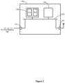
- the donor lAB 130 is shown in more detail in Figure 2 .
- the donor lAB 130 includes a first communications interface 131 for wired communications (e.g. via optical fibre) to the core network 140, a processor 133, memory 135, and a second communications interface 137 for wireless communications (e.g. via an antenna), all connected via bus 139.
- the second communications interface 137 is for providing an access connection to one or more UE (such as a fifth UE 110e of the plurality of UE), and for providing a wireless backhaul connection to one or more IAB nodes (such as the fourth lAB node 120d).
- the processor 133 of the donor lAB 130 includes both a Centralised Unit (CU) (providing Radio Resource Control (RRC) and Packet Data Convergence (PDC) functionality) and a Distributed Unit (DU) (providing Radio Link Control (RLC) and Medium Access Control (MAC) functionality) for processing packets communicated via the first or second communications interfaces 131, 137.
- CU Centralised Unit
- RRC Radio Resource Control
- PDC Packet Data Convergence
- DU Distributed Unit
- RLC Radio Link Control
- MAC Medium Access Control
- a third IAB node 120c of the plurality of IAB nodes is shown in more detail in Figure 3 .
- the third IAB node 120c includes a first communications interface 121c for wireless communications (e.g. via an antenna), a processor 123c, memory 125c, and a second communications interface 127c for wireless communications (e.g. via an antenna), all connected via bus 129c.
- the first communications interface 121c is for providing a wireless backhaul connection to the fourth IAB node 120d.
- the second communications interface 127c is for providing a wireless access connection to one or more UE (such as the third UE 110c of the plurality of UE) and for providing a wireless backhaul connection to the first and second IAB nodes 120a, 120b.
- the first communications interface 121c to a wireless backhaul connection to the fourth IAB node 120d shall hereinafter be referred to as an upstream wireless backhaul connection (as it is for communications from the third IAB node 120c to upstream network nodes such as the fourth IAB node 120d or the core network 140) and the second communications interface 127c to a wireless backhaul connection to the first and second IAB nodes 120a, 120b shall hereinafter be referred to as a downstream wireless backhaul connection (as it is for communications from the third IAB node 120c to downstream network nodes such as the first and second IAB nodes 120a, 120b).
- an upstream wireless backhaul connection as it is for communications from the third IAB node 120c to upstream network nodes such as the fourth IAB node 120d or the core network 140
- the second communications interface 127c to a wireless backhaul connection to the first and second IAB nodes 120a, 120b shall hereinafter be referred to as a downstream wireless backha
- the processor 123c of the third IAB node 120c includes a Distributed Unit (DU) (providing Radio Link Control (RLC) and Medium Access Control (MAC) functionality) for processing packets communicated via the first or second communications interfaces 121c, 127c, and further includes a Mobile Termination (MT) part for communications via the upstream wireless backhaul connection (to the DU part of the fourth lAB node 120d).
- DU Distributed Unit
- RLC Radio Link Control
- MAC Medium Access Control
- the first, second and fourth IAB nodes 120a, 120b, 120d are substantially the same as the third IAB node 120c, and the terms upstream/downstream wireless backhaul connections for these IAB nodes refer to the upstream/downstream directions from the perspective of each IAB node (that is, the upstream wireless backhaul connection for the first IAB node 120a is towards the third IAB node 120c, the upstream wireless backhaul connection for the second IAB node 120b is towards the third IAB node 120c, the upstream wireless backhaul connection for the fourth IAB node 120d is towards the IAB donor 130, and the downstream wireless backhaul connection for the fourth IAB node 120d is towards the third lAB node 120c).
- the donor lAB 130 and the IAB nodes 120a... 120d are all configured to establish an inter-Access Point (inter-AP) connection (in this embodiment, an Xn connection) with any other donor IAB or IAB node that they may connect with (directly or indirectly). Furthermore, the donor lAB 130 and each lAB node of the plurality of IAB nodes 120a... 120d store (in their respective memory modules) a routing table listing each neighbouring node it has an established inter-AP connection with (i.e. an established Xn connection).
- inter-AP inter-Access Point
- the routing table further identifies an Internet Protocol (IP) address for the neighbouring node, an identifier for the parent node of the neighbouring node, and an identifier for each child node of the neighbouring node.
- IP Internet Protocol
- a parent node is either a donor lAB or IAB node that the neighbouring node is directly connected to via its upstream wireless backhaul connection
- a child node is either a donor lAB or IAB node that the neighbouring node is directly connected to via its downstream wireless backhaul connection.
- This method includes several processes, including a message transport process and a routing table update process.
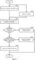
- the message transport process will now be described with reference to Figures 1 and 4 .
- the cellular telecommunications network 100 is initially in the state as shown in Figure 1 and Xn connections have been established between:
- the routing table of the first IAB node 120a includes the following data (following the update process described below): Table 1: Routing table of first IAB node 120a Neighbouring Node IP Address of Neighbouring Node Parent Node of Neighbouring Node Child Node(s) of Neighbouring Node Third IAB node 120c IP 120c Fourth IAB node 120d First IAB node 120a; Second IAB node 120b
- the routing table of the third IAB node 120c includes the following data (following the update process described below): Table 2: Routing table of third IAB node 120c Neighbouring Node IP Address of Neighbouring Node Parent Node of Neighbouring Node Child Node(s) of Neighbouring Node First IAB node 120a IP 120 . Third IAB node 120c NULL Second IAB node 120b IP 120b Third IAB node 120c NULL Fourth IAB node 120d IP 120d IAB donor 130 Third IAB node 120c
- the first IAB node 120a In a first step of the message transport process (S201), as shown in the flow diagram of Figure 4 , the first IAB node 120a generates an Xn message destined for the second IAB node 120b.
- the first IAB node 120a performs a lookup on its routing table to determine whether the first IAB node 120a has an established Xn connection with the second IAB node 120b (that is, it is listed as a neighbouring node in the routing table) or whether the second IAB node 120b is a parent or child node of a neighbouring node listed in the routing table.
- the first IAB node 120a does not have an established Xn connection with the second IAB node 120b but the second IAB node 120b is identified as a child node of the third IAB node 120b.
- the first IAB node 120a transmits the Xn message to the third IAB node 120c.
- the third IAB node 120c On receipt of the Xn message from the first IAB node 120a (step S202), the third IAB node 120c similarly performs step S203 to perform a lookup on its routing table to determine whether it has an established Xn connection with the second IAB node 120b or, if not, whether the second IAB node 120b is a parent or child node of a neighbouring node listed in the routing table. As the third IAB node 120c does have an established Xn connection with the second IAB node 120b, the third IAB node 120c responds (in step S205) by transmitting the Xn message to the second IAB node 120b.
- the second IAB node 120b therefore receives the Xn message and processes it in its normal way.
- the IAB node generating the Xn message (the first IAB node 120a) must forward it to the donor lAB 130 so that the Xn message may be forwarded to the destination node (the second IAB node 120b).
- the Xn message would have had to be forwarded via the constituent wireless backhaul connections between the first IAB node 120a and the IAB donor 130 (that is, between the first IAB node 120a and the third IAB node 120c, between the third IAB node 120c and fourth IAB node 120d, and between the fourth IAB node 120d and the donor lAB 130).
- the Xn message may be forwarded by the third IAB node 120c to the second IAB node 120b, without any interaction of the fourth IAB node 120d or donor lAB 130 and without using the respective wireless backhaul connections between the third IAB node 120c, fourth IAB node 120d and donor lAB 130.
- the above process therefore frees up capacity on these wireless backhaul connections which would otherwise be wasted forwarding these Xn messages to the donor lAB 130.
- any wireless backhaul connection that serves multiple IAB node branches will be significantly burdened.
- the above process therefore has a more significant benefit for wireless backhaul connections serving multiple IAB node branches.
- the first IAB node 120a In another example of the above process in which the first IAB node 120a generates a message destined for a destination IAB node which is not identified in either the first IAB node's routing table or third IAB node's routing table (either as a neighbouring node with which they have an established Xn connection or a parent/child node of such a neighbouring node), then the first IAB node 120a and third IAB node 120c forward the Xn message towards the IAB donor 130 (step S209). If the fourth IAB node's routing table identifies this destination IAB node, then it may process it according to the steps of the above process. If not, then the Xn message is eventually received and processed by the IAB donor 130.
- the cellular telecommunications network 100 is initially in the state as shown in Figure 1 .
- a fifth IAB node 120e is added to the network and is connected directly to the donor lAB 130 as shown in Figure 5 .
- the third UE 110c (connected to the third lAB node 120c) is within the coverage area of the fifth IAB node 120e.
- the third IAB node 120c receives a measurement report from the third UE 110c identifying the fifth IAB node 120e.
- the third IAB node 120c determines whether or not it has an established Xn connection with the fifth IAB node 120e by consulting its routing table.
- the third IAB node 120c and fifth IAB node 120e do not have an established Xn connection.
- the third IAB node 120c begins an Xn connection establishment process with the fifth IAB node 120e (step S305). Once established, the third IAB node 120c has identified the fifth IAB node 120e and has received the fifth IAB node's IP address. Similarly, the fifth IAB node 120e has identified the third IAB node 120c and has received the third IAB node's IP address.
- step S307 the third IAB node 120c sends a routing table update message (encapsulated in an Xn message) to the fifth IAB node 120e.
- This routing table update message identifies the parent node for the third IAB node 120c (in this example, the fourth lAB node 120d) and all child nodes for the third IAB node 120c (in this example, the first and second IAB nodes 120a, 120b).
- the fifth IAB node 120e stores this data in its routing table. Accordingly, the fifth IAB node's routing table includes the following data: Table 3: Routing table for the fifth IAB node 120e Neighbouring Node IP Address of Neighbouring Node Parent Node of Neighbouring Node Child Node(s) of Neighbouring Node IAB donor 130 IP 130 NULL Fourth IAB node 120d; Fifth IAB node 120e Third IAB node 120c IP 120c Fourth IAB node 120d First IAB node 120a; Second IAB node 120b
- the fifth IAB node 120e also sends a routing table update response message (encapsulated in an Xn message) to the third IAB node 120c, identifying the parent node for the fifth IAB node 120e and all child nodes for the fifth IAB node 120e.
- the donor lAB 130 is the parent node of the fifth IAB node 120e and there are no child nodes for the fifth IAB node 120e.
- the third IAB node 130c stores this data in its routing table.
- the third IAB node's routing table includes the following data: Table 4: Routing table of the third IAB node 120c Neighbouring Node IP Address of Neighbouring Node Parent Node of Neighbouring Node Child Node(s) of Neighbouring Node First IAB node 120a IP 120a Third IAB node 120c NULL Second IAB node 120b IP 120b Third IAB node 120c NULL Fourth IAB node 120d IP 120d IAB donor 130 Third IAB node 120c Fifth IAB node 120e IP 120e IAB donor 130
- step S311 the fifth IAB node 120e sends a routing table update message (encapsulated in an Xn message) to all other neighbouring nodes identified in its routing table to identify any new parent/child relationships. There are no new relationships in this example so no such message is required.
- the above process provides a mechanism for the routing tables to be updated with information on a newly added IAB node, so that the newly added IAB node may be utilised in the message transport process. Additionally, the process provides for updating routing tables following termination of an Xn connection between IAB nodes from the network (e.g. if an IAB node is removed from the network, powered down, or the Xn connection is otherwise lost). Following detection of a termination, the detecting node sends a message to all other nodes identified in its routing table to inform the other nodes of the termination. The other nodes may then update their routing tables.
- the inter-base station connections are Xn connections.
- this is non-essential and the above embodiment applies to other forms of inter-AP messages, such as X2 or S1.
Landscapes
- Engineering & Computer Science (AREA)
- Computer Networks & Wireless Communication (AREA)
- Signal Processing (AREA)
- Mobile Radio Communication Systems (AREA)
Abstract
Description
- The present invention relates to a cellular telecommunications network.
- In a cellular telecommunications network, overall capacity may be improved by increasing the density of base station deployment. However, there is an associated capital expense in providing both the additional base station equipment and the wired links connecting the additional base stations with the core network (the "backhaul"). To reduce the backhaul expenditure, access connections may be provided by relay nodes which utilise a wireless backhaul link to the core network (via a "donor" base station). Such relay nodes have become part of the 4G standards. One limitation of these 4G relay nodes is that there may only be a single relay node between the User Equipment (UE) and the donor base station (i.e. they are "single-hop").
- In 5G, relay nodes are called "Integrated Access and Backhaul" (IAB) nodes and the donor base station is called the donor lAB. 5G networks may also employ multi-hop architectures so that multiple IAB nodes may exist between the UE and the donor lAB.
- Collectively, any form of networking node that may provide an access connection in a cellular telecommunications network may be known as an Access Point (AP). This term includes the base station, donor base station, relay node, IAB node and donor lAB described above.
- Cellular telecommunications networks also utilise inter-AP messaging protocols, such as X2 in 4G and Xn in 5G. These protocols allow connections to be established between APs (directly or indirectly) in order to exchange messages concerning mobility management, load management and various configuration parameters. The donor base station in 4G networks or the donor lAB in 5G networks are responsible for routing the inter-AP messages (or have a connection to a gateway node providing such functionality), including for inter-AP messages originating from any relay node or IAB node that they serve.
- According to a first aspect of the invention, there is provided a method of operating an Access Point, AP, in a cellular telecommunications network, the cellular telecommunications network having a plurality of APs and a core network, wherein the AP is connected to a neighbouring AP of the plurality of AP via a wireless upstream connection towards the core network, the method comprising the steps of: storing data identifying the neighbouring AP, a parent AP of the neighbouring AP, and a child AP of the neighbouring AP, wherein the neighbouring AP is connected to the parent AP via a wireless upstream connection towards the core network and is connected to the child AP via a wireless downstream connection away from the core network; generating an inter-AP message destined for the child AP of the neighbouring AP; determining that the child AP is a child AP of the neighbouring AP; and, in response, sending the inter-AP message to the neighbouring AP.
- In another aspect, there is provided a method of operating an Access Point, AP, in a cellular telecommunications network, the cellular telecommunications network having a plurality of APs and a core network, wherein the AP is connected to a first subset of the plurality of APs via a wireless upstream connection towards the core network and is further connected to a second subset of the plurality of APs via a wireless downstream connection away from the core network, the method comprising the steps of: receiving an inter-AP message in a first wireless communication from a first AP of the plurality of APs, the inter-AP message comprising a destination identifier; identifying a second AP of the plurality of APs based on the destination identifier of the inter-AP message; and sending the inter-AP message to the second AP in a second wireless communication via the wireless downstream connection.
- The second AP may be the destination of the inter-AP message or a first neighbour of the second AP.
- The method may further comprise the steps of discovering the second AP; identifying the first neighbour of the second AP; recording an association between the second AP and the first neighbour of the second AP, wherein the step of identifying the second AP based on the destination of the inter-AP message utilises the recorded association between the second AP and the first neighbour of the second AP.
- The method may further comprise the steps of: detecting a termination of an inter-AP connection between the second AP and a second neighbour of the second AP; and responsive to the detection, updating a recorded association between the second AP and the second neighbour of the second AP.
- According to a second aspect of the invention, there is provided a computer program comprising instructions which, when the program is executed by a computer, cause the computer to carry out the steps of the first aspect of the invention. The computer program may be stored on a computer readable carrier medium.
- According to a third aspect of the invention, there is provided an Access Point, AP, in a cellular telecommunications network having a transceiver, memory and a processor configured to cooperate to carry out the steps of the first aspect of the invention.
- In order that the present invention may be better understood, embodiments thereof will now be described, by way of example only, with reference to the accompanying drawings in which:
-
Figure 1 is a schematic diagram of an embodiment of a cellular telecommunications network of the present invention; -
Figure 2 is a schematic diagram of a donor Integrated Access and Backhaul (IAB) of the network ofFigure 1 ; -
Figure 3 is a schematic diagram of an IAB node of the network ofFigure 1 ; -
Figure 4 is a flow diagram illustrating a message transfer process of an embodiment of a method of the present invention; -
Figure 5 is a schematic diagram of the network ofFigure 1 following introduction of a fifth IAB node; and -
Figure 6 is a flow diagram illustrating a routing table update process of the embodiment of the method of the present invention. - A first embodiment of a
cellular telecommunications network 100 of the present invention will now be described with reference toFigures 1 to 3 .Figure 1 illustrates acellular telecommunications network 100 including a plurality of User Equipment (UE) 110a...110e, a plurality of Integrated Access and Backhaul (IAB)nodes 120a... 120d, a donor lAB 130 and acore network 140, all operating according to the 5th Generation (5G) cellular telecommunications protocol as standardised by the 3rd Generation Partnership Project (3GPP). ThelAB nodes 120a... 120d are connected in a multi-hop relay architecture so that afirst IAB node 120a andsecond IAB node 120b communicate with thedonor lAB 130 via intermediate IAB nodes (thethird IAB node 120c andfourth lAB node 120d). - The
donor lAB 130 is shown in more detail inFigure 2 . The donor lAB 130 includes afirst communications interface 131 for wired communications (e.g. via optical fibre) to thecore network 140, aprocessor 133,memory 135, and asecond communications interface 137 for wireless communications (e.g. via an antenna), all connected viabus 139. Thesecond communications interface 137 is for providing an access connection to one or more UE (such as a fifth UE 110e of the plurality of UE), and for providing a wireless backhaul connection to one or more IAB nodes (such as thefourth lAB node 120d). As shown inFigure 2 , theprocessor 133 of the donor lAB 130 includes both a Centralised Unit (CU) (providing Radio Resource Control (RRC) and Packet Data Convergence (PDC) functionality) and a Distributed Unit (DU) (providing Radio Link Control (RLC) and Medium Access Control (MAC) functionality) for processing packets communicated via the first orsecond communications interfaces - A
third IAB node 120c of the plurality of IAB nodes is shown in more detail inFigure 3 . Thethird IAB node 120c includes afirst communications interface 121c for wireless communications (e.g. via an antenna), aprocessor 123c,memory 125c, and asecond communications interface 127c for wireless communications (e.g. via an antenna), all connected viabus 129c. Thefirst communications interface 121c is for providing a wireless backhaul connection to thefourth IAB node 120d. Thesecond communications interface 127c is for providing a wireless access connection to one or more UE (such as the third UE 110c of the plurality of UE) and for providing a wireless backhaul connection to the first andsecond IAB nodes first communications interface 121c to a wireless backhaul connection to thefourth IAB node 120d shall hereinafter be referred to as an upstream wireless backhaul connection (as it is for communications from thethird IAB node 120c to upstream network nodes such as thefourth IAB node 120d or the core network 140) and thesecond communications interface 127c to a wireless backhaul connection to the first andsecond IAB nodes third IAB node 120c to downstream network nodes such as the first andsecond IAB nodes - The
processor 123c of thethird IAB node 120c includes a Distributed Unit (DU) (providing Radio Link Control (RLC) and Medium Access Control (MAC) functionality) for processing packets communicated via the first orsecond communications interfaces fourth lAB node 120d). - The first, second and
fourth IAB nodes third IAB node 120c, and the terms upstream/downstream wireless backhaul connections for these IAB nodes refer to the upstream/downstream directions from the perspective of each IAB node (that is, the upstream wireless backhaul connection for thefirst IAB node 120a is towards thethird IAB node 120c, the upstream wireless backhaul connection for thesecond IAB node 120b is towards thethird IAB node 120c, the upstream wireless backhaul connection for thefourth IAB node 120d is towards theIAB donor 130, and the downstream wireless backhaul connection for thefourth IAB node 120d is towards thethird lAB node 120c). - The
donor lAB 130 and theIAB nodes 120a... 120d are all configured to establish an inter-Access Point (inter-AP) connection (in this embodiment, an Xn connection) with any other donor IAB or IAB node that they may connect with (directly or indirectly). Furthermore, thedonor lAB 130 and each lAB node of the plurality ofIAB nodes 120a... 120d store (in their respective memory modules) a routing table listing each neighbouring node it has an established inter-AP connection with (i.e. an established Xn connection). For each of these neighbouring nodes, the routing table further identifies an Internet Protocol (IP) address for the neighbouring node, an identifier for the parent node of the neighbouring node, and an identifier for each child node of the neighbouring node. In this context, a parent node is either a donor lAB or IAB node that the neighbouring node is directly connected to via its upstream wireless backhaul connection, whilst a child node is either a donor lAB or IAB node that the neighbouring node is directly connected to via its downstream wireless backhaul connection. The process of updating the routing table will be described in more detail below. - An embodiment of a method of the present invention will now be described. This method includes several processes, including a message transport process and a routing table update process. The message transport process will now be described with reference to
Figures 1 and4 . - The
cellular telecommunications network 100 is initially in the state as shown inFigure 1 and Xn connections have been established between: - The
first IAB node 120a and thethird IAB node 120c; - The
second IAB node 120b and thethird IAB node 120c; - The
third IAB node 120c and thefourth IAB node 120d; and - The
fourth IAB node 120d and theIAB donor 130. - The routing table of the
first IAB node 120a includes the following data (following the update process described below):Table 1: Routing table of first IAB node 120aNeighbouring Node IP Address of Neighbouring Node Parent Node of Neighbouring Node Child Node(s) of Neighbouring Node Third IAB node 120cIP120c Fourth IAB node 120dFirst IAB node 120a;Second IAB node 120b - The routing table of the
third IAB node 120c includes the following data (following the update process described below):Table 2: Routing table of third IAB node 120cNeighbouring Node IP Address of Neighbouring Node Parent Node of Neighbouring Node Child Node(s) of Neighbouring Node First IAB node 120aIP120. Third IAB node 120cNULL Second IAB node 120bIP120b Third IAB node 120cNULL Fourth IAB node 120dIP120d IAB donor 130 Third IAB node 120c - In a first step of the message transport process (S201), as shown in the flow diagram of
Figure 4 , thefirst IAB node 120a generates an Xn message destined for thesecond IAB node 120b. In step S203, thefirst IAB node 120a performs a lookup on its routing table to determine whether thefirst IAB node 120a has an established Xn connection with thesecond IAB node 120b (that is, it is listed as a neighbouring node in the routing table) or whether thesecond IAB node 120b is a parent or child node of a neighbouring node listed in the routing table. In this embodiment, thefirst IAB node 120a does not have an established Xn connection with thesecond IAB node 120b but thesecond IAB node 120b is identified as a child node of thethird IAB node 120b. In response (in step S207), thefirst IAB node 120a transmits the Xn message to thethird IAB node 120c. - On receipt of the Xn message from the
first IAB node 120a (step S202), thethird IAB node 120c similarly performs step S203 to perform a lookup on its routing table to determine whether it has an established Xn connection with thesecond IAB node 120b or, if not, whether thesecond IAB node 120b is a parent or child node of a neighbouring node listed in the routing table. As thethird IAB node 120c does have an established Xn connection with thesecond IAB node 120b, thethird IAB node 120c responds (in step S205) by transmitting the Xn message to thesecond IAB node 120b. - The
second IAB node 120b therefore receives the Xn message and processes it in its normal way. - The above process enables IAB nodes to route inter-AP messages towards their destination. Without this functionality, the IAB node generating the Xn message (the
first IAB node 120a) must forward it to thedonor lAB 130 so that the Xn message may be forwarded to the destination node (thesecond IAB node 120b). In this example, the Xn message would have had to be forwarded via the constituent wireless backhaul connections between thefirst IAB node 120a and the IAB donor 130 (that is, between thefirst IAB node 120a and thethird IAB node 120c, between thethird IAB node 120c andfourth IAB node 120d, and between thefourth IAB node 120d and the donor lAB 130). However, by implementing the above process, the Xn message may be forwarded by thethird IAB node 120c to thesecond IAB node 120b, without any interaction of thefourth IAB node 120d ordonor lAB 130 and without using the respective wireless backhaul connections between thethird IAB node 120c,fourth IAB node 120d anddonor lAB 130. The above process therefore frees up capacity on these wireless backhaul connections which would otherwise be wasted forwarding these Xn messages to thedonor lAB 130. Furthermore, as these multi-hop architectures may result in a tree structure with further IAB node branches (such as if the third and/orfourth IAB node IAB donor 130, then any wireless backhaul connection that serves multiple IAB node branches will be significantly burdened. The above process therefore has a more significant benefit for wireless backhaul connections serving multiple IAB node branches. - In another example of the above process in which the
first IAB node 120a generates a message destined for a destination IAB node which is not identified in either the first IAB node's routing table or third IAB node's routing table (either as a neighbouring node with which they have an established Xn connection or a parent/child node of such a neighbouring node), then thefirst IAB node 120a andthird IAB node 120c forward the Xn message towards the IAB donor 130 (step S209). If the fourth IAB node's routing table identifies this destination IAB node, then it may process it according to the steps of the above process. If not, then the Xn message is eventually received and processed by theIAB donor 130. - A process of updating the routing table will now be described with reference to
Figures 1 ,5 and6 . - The
cellular telecommunications network 100 is initially in the state as shown inFigure 1 . At a subsequent time, afifth IAB node 120e is added to the network and is connected directly to thedonor lAB 130 as shown inFigure 5 . Thethird UE 110c (connected to thethird lAB node 120c) is within the coverage area of thefifth IAB node 120e. In a first step of this routing table update process (S301), thethird IAB node 120c receives a measurement report from thethird UE 110c identifying thefifth IAB node 120e. In step S303, thethird IAB node 120c determines whether or not it has an established Xn connection with thefifth IAB node 120e by consulting its routing table. In this example, thethird IAB node 120c andfifth IAB node 120e do not have an established Xn connection. In response, thethird IAB node 120c begins an Xn connection establishment process with thefifth IAB node 120e (step S305). Once established, thethird IAB node 120c has identified thefifth IAB node 120e and has received the fifth IAB node's IP address. Similarly, thefifth IAB node 120e has identified thethird IAB node 120c and has received the third IAB node's IP address. - In step S307, the
third IAB node 120c sends a routing table update message (encapsulated in an Xn message) to thefifth IAB node 120e. This routing table update message identifies the parent node for thethird IAB node 120c (in this example, thefourth lAB node 120d) and all child nodes for thethird IAB node 120c (in this example, the first andsecond IAB nodes - On receipt, the
fifth IAB node 120e stores this data in its routing table. Accordingly, the fifth IAB node's routing table includes the following data:Table 3: Routing table for the fifth IAB node 120eNeighbouring Node IP Address of Neighbouring Node Parent Node of Neighbouring Node Child Node(s) of Neighbouring Node IAB donor 130 IP130 NULL Fourth IAB node 120d;Fifth IAB node 120eThird IAB node 120cIP120c Fourth IAB node 120dFirst IAB node 120a;Second IAB node 120b - The
fifth IAB node 120e also sends a routing table update response message (encapsulated in an Xn message) to thethird IAB node 120c, identifying the parent node for thefifth IAB node 120e and all child nodes for thefifth IAB node 120e. In this example, thedonor lAB 130 is the parent node of thefifth IAB node 120e and there are no child nodes for thefifth IAB node 120e. On receipt, in step S309, the third IAB node 130c stores this data in its routing table. Accordingly, the third IAB node's routing table includes the following data:Table 4: Routing table of the third IAB node 120cNeighbouring Node IP Address of Neighbouring Node Parent Node of Neighbouring Node Child Node(s) of Neighbouring Node First IAB node 120aIP120a Third IAB node 120cNULL Second IAB node 120bIP120b Third IAB node 120cNULL Fourth IAB node 120dIP120d IAB donor 130 Third IAB node 120cFifth IAB node 120eIP120e IAB donor 130 - Furthermore, in step S311, the
fifth IAB node 120e sends a routing table update message (encapsulated in an Xn message) to all other neighbouring nodes identified in its routing table to identify any new parent/child relationships. There are no new relationships in this example so no such message is required. - The above process provides a mechanism for the routing tables to be updated with information on a newly added IAB node, so that the newly added IAB node may be utilised in the message transport process. Additionally, the process provides for updating routing tables following termination of an Xn connection between IAB nodes from the network (e.g. if an IAB node is removed from the network, powered down, or the Xn connection is otherwise lost). Following detection of a termination, the detecting node sends a message to all other nodes identified in its routing table to inform the other nodes of the termination. The other nodes may then update their routing tables.
- In the above embodiment, the inter-base station connections are Xn connections. However, this is non-essential and the above embodiment applies to other forms of inter-AP messages, such as X2 or S1.
- The skilled person will understand that any combination of features is possible within the scope of the invention, as claimed.
- The invention may be defined by the following clauses:
- 1. A method of operating an Access Point, AP, in a cellular telecommunications network, the cellular telecommunications network having a plurality of APs and a core network, wherein the AP is connected to a first subset of the plurality of APs via a wireless upstream connection towards the core network and is further connected to a second subset of the plurality of APs via a wireless downstream connection away from the core network, the method comprising the steps of:
- receiving an inter-AP message in a first wireless communication from a first AP of the plurality of APs, the inter-AP message comprising a destination identifier;
- identifying a second AP of the plurality of APs based on the destination identifier of the inter-AP message; and
- sending the inter-AP message to the second AP in a second wireless communication via the wireless downstream connection.
- 2. A method as claimed in clause 1, wherein the second AP is the destination of the inter-AP message.
- 3. A method as claimed in clause 1, wherein the destination of the inter-AP message is a first neighbour of the second AP.
- 4. A method as claimed in clause 3, further comprising the initial steps of:
- discovering the second AP;
- identifying the first neighbour of the second AP;
- recording an association between the second AP and the first neighbour of the second AP,
- wherein the step of identifying the second AP based on the destination of the inter-AP message utilises the recorded association between the second AP and the first neighbour of the second AP.
- 5. A method as claimed in any one of the preceding clauses, further comprising the steps of:
- detecting a termination of an inter-AP connection between the second AP and a second neighbour of the second AP; and
- responsive to the detection, updating a recorded association between the second AP and the second neighbour of the second AP.
- 6. A computer program comprising instructions which, when the program is executed by a computer, cause the computer to carry out the steps of any one of clauses 1 to 5.
- 7. A computer readable carrier medium comprising the computer program of clause 6.
- 8. An Access Point, AP, in a cellular telecommunications network having a transceiver, memory and a processor configured to cooperate to carry out the steps of any one of clauses 1 to 5.
Claims (4)
- A method of operating an Access Point, AP, in a cellular telecommunications network, the cellular telecommunications network having a plurality of APs and a core network, wherein the AP is connected to a neighbouring AP of the plurality of AP via a wireless upstream connection towards the core network, the method comprising the steps of:storing data identifying the neighbouring AP, a parent AP of the neighbouring AP, and a child AP of the neighbouring AP, wherein the neighbouring AP is connected to the parent AP via a wireless upstream connection towards the core network and is connected to the child AP via a wireless downstream connection away from the core network;generating an inter-AP message destined for the child AP of the neighbouring AP;determining that the child AP is a child AP of the neighbouring AP; and, in response,sending the inter-AP message to the neighbouring AP.
- A computer program comprising instructions which, when the program is executed by a computer, cause the computer to carry out the steps of Claim 1.
- A computer readable carrier medium comprising the computer program of Claim 2.
- An Access Point, AP, in a cellular telecommunications network having a transceiver, memory and a processor configured to cooperate to carry out the steps of Claim 1.
Applications Claiming Priority (4)
| Application Number | Priority Date | Filing Date | Title |
|---|---|---|---|
| GB2004300.6A GB2593499B (en) | 2020-03-25 | 2020-03-25 | Cellular telecommunications network |
| EP20165488 | 2020-03-25 | ||
| EP21702686.3A EP4128863B1 (en) | 2020-03-25 | 2021-02-05 | Cellular telecommunications network |
| PCT/EP2021/052814 WO2021190811A1 (en) | 2020-03-25 | 2021-02-05 | Cellular telecommunications network |
Related Parent Applications (2)
| Application Number | Title | Priority Date | Filing Date |
|---|---|---|---|
| EP21702686.3A Division-Into EP4128863B1 (en) | 2020-03-25 | 2021-02-05 | Cellular telecommunications network |
| EP21702686.3A Division EP4128863B1 (en) | 2020-03-25 | 2021-02-05 | Cellular telecommunications network |
Publications (2)
| Publication Number | Publication Date |
|---|---|
| EP4171104A1 true EP4171104A1 (en) | 2023-04-26 |
| EP4171104B1 EP4171104B1 (en) | 2025-08-06 |
Family
ID=74494933
Family Applications (2)
| Application Number | Title | Priority Date | Filing Date |
|---|---|---|---|
| EP22214272.1A Active EP4171104B1 (en) | 2020-03-25 | 2021-02-05 | Cellular telecommunications network |
| EP21702686.3A Active EP4128863B1 (en) | 2020-03-25 | 2021-02-05 | Cellular telecommunications network |
Family Applications After (1)
| Application Number | Title | Priority Date | Filing Date |
|---|---|---|---|
| EP21702686.3A Active EP4128863B1 (en) | 2020-03-25 | 2021-02-05 | Cellular telecommunications network |
Country Status (4)
| Country | Link |
|---|---|
| US (1) | US20230354151A1 (en) |
| EP (2) | EP4171104B1 (en) |
| CN (2) | CN120224336A (en) |
| WO (1) | WO2021190811A1 (en) |
Families Citing this family (1)
| Publication number | Priority date | Publication date | Assignee | Title |
|---|---|---|---|---|
| US20240284294A1 (en) * | 2021-07-30 | 2024-08-22 | Sony Group Corporation | Methods and communications nodes in a wireless backhaul network |
Citations (2)
| Publication number | Priority date | Publication date | Assignee | Title |
|---|---|---|---|---|
| EP2052497A2 (en) * | 2006-08-15 | 2009-04-29 | CiscoTechnology Inc. | Route tree building in a wireless mesh network |
| EP3606180A1 (en) * | 2018-08-03 | 2020-02-05 | Fujitsu Limited | A method of securing wireless backhaul, a child base station, a parent base station and methods in the child and parent base stations |
Family Cites Families (22)
| Publication number | Priority date | Publication date | Assignee | Title |
|---|---|---|---|---|
| US7646752B1 (en) * | 2003-12-31 | 2010-01-12 | Nortel Networks Limited | Multi-hop wireless backhaul network and method |
| KR20050097674A (en) * | 2004-04-02 | 2005-10-10 | 삼성전자주식회사 | Internet connection service method of mobile node and system thereof |
| US8204039B2 (en) * | 2005-11-30 | 2012-06-19 | Symbol Technologies, Inc. | System and method for data communication in a wireless network |
| US8867428B2 (en) * | 2009-04-13 | 2014-10-21 | Qualcomm Incorporated | Split-cell relay application protocol |
| CN105101320B (en) * | 2010-05-07 | 2019-12-31 | 北京三星通信技术研究有限公司 | A method for establishing a connection between base stations |
| US8190150B1 (en) * | 2010-12-14 | 2012-05-29 | Symbol Technologies, Inc. | Synchronization of mobile device information in a wireless communication network |
| US9544782B2 (en) * | 2012-11-02 | 2017-01-10 | Qualcomm Incorporated | Systems, apparatus, and methods for range extension of wireless communication |
| US9148752B2 (en) * | 2013-04-02 | 2015-09-29 | Cisco Technology, Inc. | Scalable multi-channel ranging |
| US10122438B2 (en) * | 2013-11-01 | 2018-11-06 | Qualcomm Incorporated | Systems, methods and devices for modifying relay operation of a wireless device |
| US9467926B2 (en) * | 2014-04-28 | 2016-10-11 | Intel IP Corporation | Apparatus, method, and system of establishing a connection between a cellular node and a core network |
| WO2016029961A1 (en) * | 2014-08-29 | 2016-03-03 | Nokia Solutions And Networks Oy | Neighbouring wireless local area network access points to cellular radio access nodes |
| BR112017005888A2 (en) * | 2014-09-29 | 2018-06-26 | Huawei Technologies Co., Ltd. | A method and apparatus for shunt |
| US9967233B2 (en) * | 2015-01-21 | 2018-05-08 | Telefonaktiebolaget Lm Ericsson (Publ) | Wireless local area network access points |
| JP6517427B2 (en) * | 2015-07-30 | 2019-05-22 | ソニーモバイルコミュニケーションズ株式会社 | Mobile hotspot |
| US10250315B2 (en) * | 2015-12-30 | 2019-04-02 | Futurewei Technologies, Inc. | System and method for inter-basic service set communications |
| US10374829B2 (en) * | 2017-01-13 | 2019-08-06 | Microsoft Technology Licensing, Llc | Telecommunications network with data centre deployment |
| US10362633B2 (en) * | 2017-07-21 | 2019-07-23 | Itron Networked Solutions, Inc. | Method and system for communicating between private mesh network and public network |
| US20190281608A1 (en) * | 2018-03-09 | 2019-09-12 | Qualcomm Incorporated | Multiple access point channel planning |
| WO2020088773A1 (en) * | 2018-11-02 | 2020-05-07 | Telefonaktiebolaget Lm Ericsson (Publ) | Handling of deteriorating ap-to-ap wireless link |
| US11076348B2 (en) * | 2019-01-03 | 2021-07-27 | Samsung Electronics Co., Ltd. | Method of neighbor discovery and wireless inter-connection for cellular mesh network |
| GB2583521B (en) * | 2019-05-02 | 2022-01-12 | Samsung Electronics Co Ltd | Relay network routing |
| US11395186B2 (en) * | 2019-10-17 | 2022-07-19 | Qualcomm Incorporated | Profile-based client steering in multiple access point (AP) networks |
-
2021
- 2021-02-05 US US17/907,379 patent/US20230354151A1/en active Pending
- 2021-02-05 EP EP22214272.1A patent/EP4171104B1/en active Active
- 2021-02-05 CN CN202510589525.1A patent/CN120224336A/en active Pending
- 2021-02-05 EP EP21702686.3A patent/EP4128863B1/en active Active
- 2021-02-05 WO PCT/EP2021/052814 patent/WO2021190811A1/en not_active Ceased
- 2021-02-05 CN CN202180016439.1A patent/CN115152263B/en active Active
Patent Citations (2)
| Publication number | Priority date | Publication date | Assignee | Title |
|---|---|---|---|---|
| EP2052497A2 (en) * | 2006-08-15 | 2009-04-29 | CiscoTechnology Inc. | Route tree building in a wireless mesh network |
| EP3606180A1 (en) * | 2018-08-03 | 2020-02-05 | Fujitsu Limited | A method of securing wireless backhaul, a child base station, a parent base station and methods in the child and parent base stations |
Also Published As
| Publication number | Publication date |
|---|---|
| EP4128863B1 (en) | 2025-01-01 |
| CN120224336A (en) | 2025-06-27 |
| EP4171104B1 (en) | 2025-08-06 |
| US20230354151A1 (en) | 2023-11-02 |
| WO2021190811A1 (en) | 2021-09-30 |
| CN115152263B (en) | 2025-07-25 |
| CN115152263A (en) | 2022-10-04 |
| EP4128863A1 (en) | 2023-02-08 |
Similar Documents
| Publication | Publication Date | Title |
|---|---|---|
| US11452009B2 (en) | Communication system | |
| WO2020059470A1 (en) | Systems, devices, and methods for connection reestablishment via alternative routes in integrated access and backhaul due to radio link failures | |
| US20200344843A1 (en) | Node and communication method | |
| US20240205795A1 (en) | Methods for enabling inter-donor routing in iab networks | |
| JP2001500342A (en) | Method and apparatus for rerouting a connection in a telecommunications network connection including a plurality of network elements | |
| JPWO2005109764A1 (en) | Wireless node device and multi-hop wireless LAN system | |
| US20240031860A1 (en) | Communication method and device | |
| KR20240134365A (en) | Inter-donor migration for INTEGRATED ACCESS AND BACKHAUL (IAB) nodes | |
| GB2593499A (en) | Cellular telecommunications network | |
| EP4128863B1 (en) | Cellular telecommunications network | |
| CN118140587A (en) | Wireless routing method and device | |
| US20240388964A1 (en) | Iab-donor device and transport migration management method | |
| GB2605960A (en) | Routing data in an integrated access and backhaul network | |
| KR20230042334A (en) | Signaling exchange method in wireless communication | |
| EP4694229A1 (en) | Signal transceiving method and apparatus and communication system | |
| EP4664961A1 (en) | Information processing method and apparatus | |
| US20240048486A1 (en) | Routing data in an integrated access and backhaul network | |
| GB2611233A (en) | Cellular telecommunications network | |
| JP2026513333A (en) | Distributed unit migration method, control device and communication system | |
| EP4510692A1 (en) | Information configuration method and apparatus, and communication system | |
| KR20060128040A (en) | Method of communication in LAN with group of relay stations and wireless access points | |
| JP7806927B2 (en) | Method and apparatus for setting information and communication system | |
| JP2020178176A (en) | Communication systems, communication devices, and terminal devices | |
| WO2024139892A1 (en) | Communication method and apparatus |
Legal Events
| Date | Code | Title | Description |
|---|---|---|---|
| PUAI | Public reference made under article 153(3) epc to a published international application that has entered the european phase |
Free format text: ORIGINAL CODE: 0009012 |
|
| STAA | Information on the status of an ep patent application or granted ep patent |
Free format text: STATUS: THE APPLICATION HAS BEEN PUBLISHED |
|
| AC | Divisional application: reference to earlier application |
Ref document number: 4128863 Country of ref document: EP Kind code of ref document: P |
|
| AK | Designated contracting states |
Kind code of ref document: A1 Designated state(s): AL AT BE BG CH CY CZ DE DK EE ES FI FR GB GR HR HU IE IS IT LI LT LU LV MC MK MT NL NO PL PT RO RS SE SI SK SM TR |
|
| P01 | Opt-out of the competence of the unified patent court (upc) registered |
Effective date: 20230623 |
|
| STAA | Information on the status of an ep patent application or granted ep patent |
Free format text: STATUS: REQUEST FOR EXAMINATION WAS MADE |
|
| 17P | Request for examination filed |
Effective date: 20240115 |
|
| RBV | Designated contracting states (corrected) |
Designated state(s): AL AT BE BG CH CY CZ DE DK EE ES FI FR GB GR HR HU IE IS IT LI LT LU LV MC MK MT NL NO PL PT RO RS SE SI SK SM TR |
|
| GRAP | Despatch of communication of intention to grant a patent |
Free format text: ORIGINAL CODE: EPIDOSNIGR1 |
|
| STAA | Information on the status of an ep patent application or granted ep patent |
Free format text: STATUS: GRANT OF PATENT IS INTENDED |
|
| RIC1 | Information provided on ipc code assigned before grant |
Ipc: H04W 92/20 20090101ALN20250211BHEP Ipc: H04W 40/22 20090101ALI20250211BHEP Ipc: H04W 24/02 20090101AFI20250211BHEP |
|
| RIC1 | Information provided on ipc code assigned before grant |
Ipc: H04W 92/20 20090101ALN20250225BHEP Ipc: H04W 40/22 20090101ALI20250225BHEP Ipc: H04W 24/02 20090101AFI20250225BHEP |
|
| RIN1 | Information on inventor provided before grant (corrected) |
Inventor name: DIAZ SENDRA, SALVADOR |
|
| INTG | Intention to grant announced |
Effective date: 20250310 |
|
| GRAS | Grant fee paid |
Free format text: ORIGINAL CODE: EPIDOSNIGR3 |
|
| GRAA | (expected) grant |
Free format text: ORIGINAL CODE: 0009210 |
|
| STAA | Information on the status of an ep patent application or granted ep patent |
Free format text: STATUS: THE PATENT HAS BEEN GRANTED |
|
| AC | Divisional application: reference to earlier application |
Ref document number: 4128863 Country of ref document: EP Kind code of ref document: P |
|
| AK | Designated contracting states |
Kind code of ref document: B1 Designated state(s): AL AT BE BG CH CY CZ DE DK EE ES FI FR GB GR HR HU IE IS IT LI LT LU LV MC MK MT NL NO PL PT RO RS SE SI SK SM TR |
|
| REG | Reference to a national code |
Ref country code: GB Ref legal event code: FG4D |
|
| REG | Reference to a national code |
Ref country code: CH Ref legal event code: EP |
|
| REG | Reference to a national code |
Ref country code: DE Ref legal event code: R096 Ref document number: 602021035915 Country of ref document: DE |
|
| REG | Reference to a national code |
Ref country code: IE Ref legal event code: FG4D |
|
| REG | Reference to a national code |
Ref country code: NL Ref legal event code: MP Effective date: 20250806 |
|
| PG25 | Lapsed in a contracting state [announced via postgrant information from national office to epo] |
Ref country code: IS Free format text: LAPSE BECAUSE OF FAILURE TO SUBMIT A TRANSLATION OF THE DESCRIPTION OR TO PAY THE FEE WITHIN THE PRESCRIBED TIME-LIMIT Effective date: 20251206 |
|
| PG25 | Lapsed in a contracting state [announced via postgrant information from national office to epo] |
Ref country code: NO Free format text: LAPSE BECAUSE OF FAILURE TO SUBMIT A TRANSLATION OF THE DESCRIPTION OR TO PAY THE FEE WITHIN THE PRESCRIBED TIME-LIMIT Effective date: 20251106 |
|
| REG | Reference to a national code |
Ref country code: LT Ref legal event code: MG9D |
|
| PG25 | Lapsed in a contracting state [announced via postgrant information from national office to epo] |
Ref country code: PT Free format text: LAPSE BECAUSE OF FAILURE TO SUBMIT A TRANSLATION OF THE DESCRIPTION OR TO PAY THE FEE WITHIN THE PRESCRIBED TIME-LIMIT Effective date: 20251209 |
|
| PG25 | Lapsed in a contracting state [announced via postgrant information from national office to epo] |
Ref country code: FI Free format text: LAPSE BECAUSE OF FAILURE TO SUBMIT A TRANSLATION OF THE DESCRIPTION OR TO PAY THE FEE WITHIN THE PRESCRIBED TIME-LIMIT Effective date: 20250806 |
|
| PG25 | Lapsed in a contracting state [announced via postgrant information from national office to epo] |
Ref country code: HR Free format text: LAPSE BECAUSE OF FAILURE TO SUBMIT A TRANSLATION OF THE DESCRIPTION OR TO PAY THE FEE WITHIN THE PRESCRIBED TIME-LIMIT Effective date: 20250806 Ref country code: NL Free format text: LAPSE BECAUSE OF FAILURE TO SUBMIT A TRANSLATION OF THE DESCRIPTION OR TO PAY THE FEE WITHIN THE PRESCRIBED TIME-LIMIT Effective date: 20250806 |
|
| PG25 | Lapsed in a contracting state [announced via postgrant information from national office to epo] |
Ref country code: GR Free format text: LAPSE BECAUSE OF FAILURE TO SUBMIT A TRANSLATION OF THE DESCRIPTION OR TO PAY THE FEE WITHIN THE PRESCRIBED TIME-LIMIT Effective date: 20251107 |
|
| PG25 | Lapsed in a contracting state [announced via postgrant information from national office to epo] |
Ref country code: SE Free format text: LAPSE BECAUSE OF FAILURE TO SUBMIT A TRANSLATION OF THE DESCRIPTION OR TO PAY THE FEE WITHIN THE PRESCRIBED TIME-LIMIT Effective date: 20250806 |
|
| PG25 | Lapsed in a contracting state [announced via postgrant information from national office to epo] |
Ref country code: LV Free format text: LAPSE BECAUSE OF FAILURE TO SUBMIT A TRANSLATION OF THE DESCRIPTION OR TO PAY THE FEE WITHIN THE PRESCRIBED TIME-LIMIT Effective date: 20250806 |
|
| PG25 | Lapsed in a contracting state [announced via postgrant information from national office to epo] |
Ref country code: BG Free format text: LAPSE BECAUSE OF FAILURE TO SUBMIT A TRANSLATION OF THE DESCRIPTION OR TO PAY THE FEE WITHIN THE PRESCRIBED TIME-LIMIT Effective date: 20250806 Ref country code: PL Free format text: LAPSE BECAUSE OF FAILURE TO SUBMIT A TRANSLATION OF THE DESCRIPTION OR TO PAY THE FEE WITHIN THE PRESCRIBED TIME-LIMIT Effective date: 20250806 |
|
| PG25 | Lapsed in a contracting state [announced via postgrant information from national office to epo] |
Ref country code: RS Free format text: LAPSE BECAUSE OF FAILURE TO SUBMIT A TRANSLATION OF THE DESCRIPTION OR TO PAY THE FEE WITHIN THE PRESCRIBED TIME-LIMIT Effective date: 20251106 |
|
| PG25 | Lapsed in a contracting state [announced via postgrant information from national office to epo] |
Ref country code: ES Free format text: LAPSE BECAUSE OF FAILURE TO SUBMIT A TRANSLATION OF THE DESCRIPTION OR TO PAY THE FEE WITHIN THE PRESCRIBED TIME-LIMIT Effective date: 20250806 |
|
| REG | Reference to a national code |
Ref country code: AT Ref legal event code: MK05 Ref document number: 1823411 Country of ref document: AT Kind code of ref document: T Effective date: 20250806 |
|
| PG25 | Lapsed in a contracting state [announced via postgrant information from national office to epo] |
Ref country code: SM Free format text: LAPSE BECAUSE OF FAILURE TO SUBMIT A TRANSLATION OF THE DESCRIPTION OR TO PAY THE FEE WITHIN THE PRESCRIBED TIME-LIMIT Effective date: 20250806 |
|
| PGFP | Annual fee paid to national office [announced via postgrant information from national office to epo] |
Ref country code: GB Payment date: 20260121 Year of fee payment: 6 |
|
| PG25 | Lapsed in a contracting state [announced via postgrant information from national office to epo] |
Ref country code: DK Free format text: LAPSE BECAUSE OF FAILURE TO SUBMIT A TRANSLATION OF THE DESCRIPTION OR TO PAY THE FEE WITHIN THE PRESCRIBED TIME-LIMIT Effective date: 20250806 |
|
| PGFP | Annual fee paid to national office [announced via postgrant information from national office to epo] |
Ref country code: DE Payment date: 20260121 Year of fee payment: 6 |
|
| PG25 | Lapsed in a contracting state [announced via postgrant information from national office to epo] |
Ref country code: AT Free format text: LAPSE BECAUSE OF FAILURE TO SUBMIT A TRANSLATION OF THE DESCRIPTION OR TO PAY THE FEE WITHIN THE PRESCRIBED TIME-LIMIT Effective date: 20250806 |
|
| PG25 | Lapsed in a contracting state [announced via postgrant information from national office to epo] |
Ref country code: IT Free format text: LAPSE BECAUSE OF FAILURE TO SUBMIT A TRANSLATION OF THE DESCRIPTION OR TO PAY THE FEE WITHIN THE PRESCRIBED TIME-LIMIT Effective date: 20250806 |
|
| PGFP | Annual fee paid to national office [announced via postgrant information from national office to epo] |
Ref country code: FR Payment date: 20260121 Year of fee payment: 6 |
|
| PG25 | Lapsed in a contracting state [announced via postgrant information from national office to epo] |
Ref country code: CZ Free format text: LAPSE BECAUSE OF FAILURE TO SUBMIT A TRANSLATION OF THE DESCRIPTION OR TO PAY THE FEE WITHIN THE PRESCRIBED TIME-LIMIT Effective date: 20250806 |
|
| PG25 | Lapsed in a contracting state [announced via postgrant information from national office to epo] |
Ref country code: EE Free format text: LAPSE BECAUSE OF FAILURE TO SUBMIT A TRANSLATION OF THE DESCRIPTION OR TO PAY THE FEE WITHIN THE PRESCRIBED TIME-LIMIT Effective date: 20250806 Ref country code: SK Free format text: LAPSE BECAUSE OF FAILURE TO SUBMIT A TRANSLATION OF THE DESCRIPTION OR TO PAY THE FEE WITHIN THE PRESCRIBED TIME-LIMIT Effective date: 20250806 |
|
| REG | Reference to a national code |
Ref country code: DE Ref legal event code: R097 Ref document number: 602021035915 Country of ref document: DE |
|
| PLBE | No opposition filed within time limit |
Free format text: ORIGINAL CODE: 0009261 |
|
| STAA | Information on the status of an ep patent application or granted ep patent |
Free format text: STATUS: NO OPPOSITION FILED WITHIN TIME LIMIT |
|
| REG | Reference to a national code |
Ref country code: CH Ref legal event code: L10 Free format text: ST27 STATUS EVENT CODE: U-0-0-L10-L00 (AS PROVIDED BY THE NATIONAL OFFICE) Effective date: 20260617 |
|
| PG25 | Lapsed in a contracting state [announced via postgrant information from national office to epo] |
Ref country code: LT Free format text: LAPSE BECAUSE OF FAILURE TO SUBMIT A TRANSLATION OF THE DESCRIPTION OR TO PAY THE FEE WITHIN THE PRESCRIBED TIME-LIMIT Effective date: 20250806 |
|
| 26N | No opposition filed |
Effective date: 20260507 |