EP4170936A1 - Phase determination method and apparatus, phase calibration method, medium, and antenna device - Google Patents
Phase determination method and apparatus, phase calibration method, medium, and antenna device Download PDFInfo
- Publication number
- EP4170936A1 EP4170936A1 EP21832242.8A EP21832242A EP4170936A1 EP 4170936 A1 EP4170936 A1 EP 4170936A1 EP 21832242 A EP21832242 A EP 21832242A EP 4170936 A1 EP4170936 A1 EP 4170936A1
- Authority
- EP
- European Patent Office
- Prior art keywords
- current offset
- direct
- offset signal
- target
- channels
- Prior art date
- Legal status (The legal status is an assumption and is not a legal conclusion. Google has not performed a legal analysis and makes no representation as to the accuracy of the status listed.)
- Pending
Links
Images



Classifications
-
- H—ELECTRICITY
- H04—ELECTRIC COMMUNICATION TECHNIQUE
- H04B—TRANSMISSION
- H04B17/00—Monitoring; Testing
- H04B17/20—Monitoring; Testing of receivers
- H04B17/21—Monitoring; Testing of receivers for calibration; for correcting measurements
-
- H—ELECTRICITY
- H01—ELECTRIC ELEMENTS
- H01Q—ANTENNAS, i.e. RADIO AERIALS
- H01Q3/00—Arrangements for changing or varying the orientation or the shape of the directional pattern of the waves radiated from an antenna or antenna system
- H01Q3/26—Arrangements for changing or varying the orientation or the shape of the directional pattern of the waves radiated from an antenna or antenna system varying the relative phase or relative amplitude of energisation between two or more active radiating elements; varying the distribution of energy across a radiating aperture
-
- H—ELECTRICITY
- H01—ELECTRIC ELEMENTS
- H01Q—ANTENNAS, i.e. RADIO AERIALS
- H01Q3/00—Arrangements for changing or varying the orientation or the shape of the directional pattern of the waves radiated from an antenna or antenna system
- H01Q3/26—Arrangements for changing or varying the orientation or the shape of the directional pattern of the waves radiated from an antenna or antenna system varying the relative phase or relative amplitude of energisation between two or more active radiating elements; varying the distribution of energy across a radiating aperture
- H01Q3/267—Phased-array testing or checking devices
-
- H—ELECTRICITY
- H04—ELECTRIC COMMUNICATION TECHNIQUE
- H04B—TRANSMISSION
- H04B17/00—Monitoring; Testing
- H04B17/0082—Monitoring; Testing using service channels; using auxiliary channels
- H04B17/0085—Monitoring; Testing using service channels; using auxiliary channels using test signal generators
-
- H—ELECTRICITY
- H04—ELECTRIC COMMUNICATION TECHNIQUE
- H04B—TRANSMISSION
- H04B17/00—Monitoring; Testing
- H04B17/10—Monitoring; Testing of transmitters
- H04B17/101—Monitoring; Testing of transmitters for measurement of specific parameters of the transmitter or components thereof
-
- H—ELECTRICITY
- H04—ELECTRIC COMMUNICATION TECHNIQUE
- H04B—TRANSMISSION
- H04B17/00—Monitoring; Testing
- H04B17/10—Monitoring; Testing of transmitters
- H04B17/101—Monitoring; Testing of transmitters for measurement of specific parameters of the transmitter or components thereof
- H04B17/104—Monitoring; Testing of transmitters for measurement of specific parameters of the transmitter or components thereof of other parameters, e.g. DC offset, delay or propagation times
-
- H—ELECTRICITY
- H04—ELECTRIC COMMUNICATION TECHNIQUE
- H04B—TRANSMISSION
- H04B17/00—Monitoring; Testing
- H04B17/10—Monitoring; Testing of transmitters
- H04B17/11—Monitoring; Testing of transmitters for calibration
- H04B17/12—Monitoring; Testing of transmitters for calibration of transmit antennas, e.g. of the amplitude or phase
-
- H—ELECTRICITY
- H04—ELECTRIC COMMUNICATION TECHNIQUE
- H04B—TRANSMISSION
- H04B17/00—Monitoring; Testing
- H04B17/10—Monitoring; Testing of transmitters
- H04B17/11—Monitoring; Testing of transmitters for calibration
- H04B17/14—Monitoring; Testing of transmitters for calibration of the whole transmission and reception path, e.g. self-test loop-back
-
- H—ELECTRICITY
- H04—ELECTRIC COMMUNICATION TECHNIQUE
- H04B—TRANSMISSION
- H04B17/00—Monitoring; Testing
- H04B17/20—Monitoring; Testing of receivers
- H04B17/21—Monitoring; Testing of receivers for calibration; for correcting measurements
- H04B17/22—Monitoring; Testing of receivers for calibration; for correcting measurements for calibration of the receiver components
- H04B17/221—Monitoring; Testing of receivers for calibration; for correcting measurements for calibration of the receiver components of receiver antennas, e.g. as to amplitude or phase
-
- G—PHYSICS
- G01—MEASURING; TESTING
- G01R—MEASURING ELECTRIC VARIABLES; MEASURING MAGNETIC VARIABLES
- G01R21/00—Arrangements for measuring electric power or power factor
- G01R21/06—Arrangements for measuring electric power or power factor by measuring current and voltage
Definitions
- the present disclosure relates to the field of communication technology.
- the phased array technology can obviously improve the signal-to-noise ratio and the sensitivity of a wireless communication system.
- the requirements on the power and noise of a single channel in a phased array system can be reduced, thereby facilitating wide application of the phased array technology.
- the present disclosure provides a phase calibration method, including: generating a system direct-current offset signal of a phased array system corresponding to N target channels to be calibrated, and outputting a voltage amplitude of the system direct-current offset signal; adjusting initial phases of the N target channels, wherein each time the initial phases of the N target channels are adjusted to another phase value, test signals are provided for the N target channels so that a mixer downstream of a power combiner of the phased array system outputs a total direct-current offset signal, as well as a voltage amplitude of the total direct-current offset signal; determining, with the method for determining a target initial phase according to the present disclosure, a target initial phase of the N target channels; and respectively adjusting the initial phases of the target channels to the target initial phase.
- the present disclosure provides an apparatus for determining a target initial phase, including: a memory module having a computer program stored thereon, and one or more processors which invoke the computer program to implement the method for determining a target initial phase according to the present disclosure.
- the present disclosure provides a computer-readable storage medium having a computer program stored thereon which, when invoked by a processor, causes the processor to implement the method for determining a target initial phase according to the present disclosure.
- the present disclosure provides an antenna device, including: a phased array system; and a target initial phase determining apparatus according to the present disclosure.
- FIG. 1 is a framework diagram of a phased array system in the related art.
- a power combination or distribution network distributes power to each channel, and by means of a controllable phase difference of different channels, the beam pointing can be changed and effective beam forming can be performed.
- the phased array system due to a relatively large number of channels in the phased array system, it is difficult to guarantee that all channels has a same initial phase because different channels differ from each other in the processing and manufacturing and in the ambient environment, leading to reduced beam forming performance. Therefore, how to calibrate phases of channels in the phased array system has become a technical problem to be solved in the field.
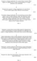
- the present disclosure provides a method for determining a target initial phase. As shown in FIG. 3 , the method for determining a target initial phase includes the following operations S110 to S130.
- the total direct-current offset signal is a total direct-current offset signal of an initial mixed signal output from a mixer downstream of a power combiner of the phased array system after test signals are provided for the N target channels.
- V dc mix V dc tot ⁇ V dc int
- V dc int the voltage amplitude of the system direct-current offset signal
- V dc tot the voltage amplitude of the total direct-current offset signal
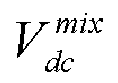
- V dc mix the voltage amplitude of the mixed direct-current offset signal
- N the number of channels in the phased array system.
- the "respectively acquiring voltage amplitudes of a total direct-current offset signal under different initial phases" herein means that each time the voltage amplitude of the total direct-current offset signal is acquired, the N target channels have a same initial phase.
- the method for determining a target initial phase of the present disclosure is a mixer principle-based method.
- the principle of the mixer is briefly explained below with reference to FIG. 2 .
- V RF is a voltage amplitude of a radio frequency (RF) signal
- V LO is a voltage amplitude of a local oscillator signal
- w RF is an angular frequency of the RF signal
- w LO is an angular frequency of the local oscillator signal
- ⁇ RF is a phase of the RF signal
- ⁇ LO is a phase of the local
- the first equation in formula (2) shows that a basic mathematical principle of the mixing by the mixer is multiplying two signals, and then converting the product to the second equation in formula (2) through the prosthaphaeresis formula, namely, calculating a sum or difference in frequency domain.
- a low-pass filter is typically provided at an output end of the mixer to filter out a high-frequency term in formula (2), and obtained an output signal as shown in formula (3):
- V OUT 1 2
- the formula (3) shows acquiring a difference frequency signal generated by mixing, where the frequency of the difference frequency signal is a difference between frequencies of the two mixed signals, and the initial phase is a difference between initial phases of the two mixed signals.
- V OUT ′ A MIXER ⁇ V RF V LO 2 cos ⁇ RF ⁇ ⁇ LO
- the final output after mixing is a direct-current component which has a magnitude associated with initial phases of the two mixed signals.
- the direct-current component output from the mixer reaches a maximum value.
- a signal obtained by mixing the superimposed signal y in the mixer may be expressed by formula (6):
- B is the voltage amplitude of the local oscillator signal
- w is the angular frequency of the local oscillator signal
- ⁇ 0 is the phase of the local oscillator signal.
- the mixed direct-current offset signal generated after the mixing in the mixer is superimposed with the initial system direct-current offset signal of the phased array system (i.e., the system direct-current offset signal obtained in operation S110) to obtain the total direct-current offset signal of the phased array system. Therefore, when determining the direct-current offset signal (i.e., the mixed direct-current offset signal) generated from the mixed signal of the test signal in each channel, the initial system direct-current offset signal needs to be subtracted from the obtained total direct-current offset signal output from the analog-to-digital converter, thus the mixed direct-current offset signal is calculated from above formula (1).
- the mixed direct-current offset signal V dc mix in formula (1) is the optimization target used for adjusting the phase of each channel.
- the mixed direct-current offset signal V dc mix reaches the maximum value, it indicates that all channels has a same initial phase equal to the initial phase of the local oscillator signal.
- a coupler is usually added to an antenna end of the phased array system to perform initial phase calibration of channels in combination with phase discrimination.
- a coupler is desired to be introduced into each antenna port, and the scheme is complex due to complex signal traces from the coupler to the phase discriminator.
- inconsistency of the large number of traces between the coupler and the phase discriminator may cause calibration deviations, and thus reduce the calibration accuracy.
- signals of the channels in the phased array system are each subjected to self-mixing in the mixer to obtain the target initial phase of each target channel, thereby simplifying the calibration process.
- no additional calibration device is desired, no additional calibration deviation is introduced, and the calibration accuracy is thus improved.
- the target channel may be a receiving channel or a transmitting channel.
- the following describes the method for determining a target initial phase of the present disclosure in detail under the two cases, i.e., the target initial phase is a receiving channel and the target channel is a transmitting channel, respectively.
- the voltage amplitude of the system direct-current offset signal in operation S110 may be obtained by: opening N receiving channels; and determining an output value of an analog-to-digital converter (ADC) of the phased array system as the voltage amplitude of the system direct-current offset signal.
- ADC analog-to-digital converter
- the voltage amplitude of the system direct-current offset signal in operation S110 is an output value of the ADC downstream of the mixer after the N receiving channels are opened.
- the obtained voltage amplitude of the initial system direct-current offset signal is a voltage amplitude corresponding to a sum of direct-current offset signals generated by all devices (for example, a transimpedance amplifier, a filter, etc.) from the mixer to the ADC of the phased array system, as well as a voltage amplitude of the system direct-current offset signal of the phased array system.
- test signals are not particularly limited in the present disclosure.
- the test signals may be single tone signals transmitted from a transmitter antenna of a single channel used for calibration.
- the voltage amplitude of the total direct-current offset signal is an output value of the ADC after the N receiving channels are opened.
- the voltage amplitude of the system direct-current offset signal in operation S110 is an output value of an ADC downstream of the mixer after a receiving channel for calibration is opened.
- test signals are not particularly limited in the present disclosure.
- the test signals provided for the N target channels may be single tone signals transmitted through a multi-channel transmitter antenna of the phased array system.
- the voltage amplitude of the total direct-current offset signal is an output value of the ADC after the receiving channel for calibration is opened.
- the present disclosure provides a phase calibration method. As shown in FIG. 4 , the phase calibration method includes the following operations S210 to S240.
- test signals are provided for the N target channels so that a mixer downstream of a power combiner of the phased array system outputs a total direct-current offset signal, as well as a voltage amplitude of the total direct-current offset signal.
- signals of the channels in the phased array system are each subjected to self-mixing in the mixer to obtain the target initial phase of each target channel, thereby simplifying the calibration process.
- no additional calibration device is desired, no additional calibration deviation is introduced, and the calibration accuracy is thus improved.
- each channel in the phased array system corresponds to a phase shifter that may be configured to adjust the phase of each target channel.
- the target channel may be a receiving channel or a transmitting channel.
- the following describes the phase calibration method in the cases where the target channel is a receiving channel and where the target channel is a transmitting channel.
- operation S210 may include the following operations S211a to S212a.
- operation S220 may include the following operations S221a to S222a.
- the calibration method for receiving channels is further described in detail below with reference to FIGs. 5 and 6 .
- This direct-current offset signal is the system direct-current offset signal.
- V dc initRX the system direct-current offset signal.
- a direct-current offset corresponding to this direct-current offset signal is a sum of direct-current offsets generated by all devices from the mixer to the ADC.
- the formula (5) shows that the signal at the power combiner is a superposition of the signals received by the receiving channels after channel amplification and initial phase adjustment.
- the formula (6) shows that based on the mixing principle of formula (2), the mixing of the output of the power combiner and the local oscillator signal of the mixer means multiplying a plurality of cosine signals by the local oscillator signal.
- the above formula shows that the received signal has the same frequency as the local oscillator signal, and shows the remaining difference frequency signal after the high-frequency signal is filtered out.
- the difference frequency signal in this case is a direct-current component which reaches a maximum value when initial phases of all cosine signals are the same as the initial phase of the local oscillator signal.
- V dc totRX V dc totRX ⁇ V dc initRX .
- the formula (8) shows that the condition for the direct-current component generated by mixing reaches the maximum value is that initial phases of all receiving channels are the same as the initial phase of the local oscillator signal.
- operation S210 may include the following operations S211b to S212b.
- test signals are not particularly limited.
- single tone signals transmitted through a multi-channel transmitter antenna may be used as the test signals.
- operation S220 may include the following operations S221b to S222b.
- the calibration method for transmitting channels is further described in detail below with reference to FIGs. 7 and 8 .
- This direct-current offset signal corresponding a direct-current offset is a sum of direct-current offsets generated by all devices from the mixer to the ADC, which is a system direct-current offset signal from direct-current offset by the receiving channel for calibration.
- the signal before the mixer of the receiving channel for calibration is a superposition of signals from transmitting channels to be calibrated, which signals may have different amplitudes and initial phases, but have a same frequency.
- the above formula shows that based on the mixing principle of formula (2), the mixing of the input of the mixer of the receiving channel for calibration and the local oscillator signal of the mixer means multiplying a plurality of cosine signals by the local oscillator signal.
- V dc mixTX B 2 * A 1 * cos ⁇ 1 ⁇ ⁇ 0 + A 2 * cos ⁇ 2 ⁇ ⁇ 0 + ... + A n * cos ⁇ n ⁇ ⁇ 0
- the above formula shows that the transmitted signals have the same frequency as the local oscillator signal of the receiving channel for calibration, and shows the remaining difference frequency signal after the high-frequency signal is filtered out in the receiving channel for calibration.
- the difference frequency signal in this case is a direct-current component which reaches a maximum value when initial phases of all cosine signals are the same as the initial phase of the local oscillator signal.
- V dc totTX V dc totTX ⁇ V dc initTX .
- the formula (9) shows that the condition for the direct-current component generated by mixing reaches the maximum value is that initial phases of all transmitting channels are the same as the initial phase of the local oscillator signal.
- phase calibration method of the present disclosure is described below taking the case where the number N of channels is 2 as an example.
- phase calibration method for receiving channels is described in detail below with reference to FIG. 5 and 9 .
- This direct-current offset signal corresponding a direct-current offset is a sum of direct-current offsets generated by all devices from the mixer to the ADC, which is an initial value of the system direct-current offset signal.
- the above formula shows that the signal at the power combiner is a superposition of the signals received by the receiving channels after channel amplification and initial phase adjustment.
- V dc mixRX B 2 * A 1 * cos ⁇ 1 ⁇ ⁇ 0 + A 2 * cos ⁇ 2 ⁇ ⁇ 0
- the above formula shows that the received signal has the same frequency as the local oscillator signal, and shows the remaining difference frequency signal after the high-frequency signal is filtered out.
- the difference frequency signal in this case is a direct-current component which reaches a maximum value when initial phases of the two cosine signals are both the same as the initial phase of the local oscillator signal.
- V dc totRX V dc totRX ⁇ V dc initRX .
- the formula (10) shows that the condition for the direct-current component generated by mixing reaches the maximum value is that initial phases of the two receiving channels are both the same as the initial phase of the local oscillator signal.
- phase calibration method for receiving channels is described in detail below with reference to FIG. 7 and 10 .
- This direct-current offset signal corresponding a direct-current offset is a sum of direct-current offsets generated by all devices from the mixer to the ADC, which is a system direct-current offset signal from direct-current offset by the receiving channel for calibration.
- the signal before the mixer of the receiving channel for calibration is a superposition of signals from the two transmitting channels to be calibrated, which signals may have different amplitudes and initial phases, but have a same frequency.
- V dc mixTX B 2 * A 1 * cos ⁇ 1 ⁇ ⁇ 0 + A 2 * cos ⁇ 2 ⁇ ⁇ 0
- the above formula shows that the two transmitted signals have the same frequency as the local oscillator signal of the receiving channel for calibration, and shows the remaining difference frequency signal after the high-frequency signal is filtered out in the receiving channel for calibration.
- the difference frequency signal in this case is a direct-current component which reaches a maximum value when initial phases of the two cosine signals are both the same as the initial phase of the local oscillator signal.
- V dc totTX V dc totTX ⁇ V dc initTX .
- the formula (11) shows that the condition for the direct-current component generated by mixing reaches the maximum value is that initial phases of the two transmitting channels are both the same as the initial phase of the local oscillator signal.
- the present disclosure provides an apparatus for determining a target initial phase, including: a memory module having a computer program stored thereon, and one or more processors which invoke the computer program to implement the method for determining a target initial phase according to the present disclosure.
- the apparatus for determining a target initial phase may further include a read/write (I/O) interface connected between the one or more processors and the memory module to enable information interaction between the one or more processors and the memory module.
- I/O read/write
- Each processor is a device with a data processing capability, including but not limited to a central processing unit (CPU) or the like; and the memory module is a device with a data storage capability, including but not limited to a random access memory (RAM, more specifically SDRAM, DDR, etc.), a read only memory (ROM), an electrically erasable programmable read only memory (EEPROM) or a flash memory (FLASH).
- RAM random access memory
- ROM read only memory
- EEPROM electrically erasable programmable read only memory
- FLASH flash memory
- the I/O interface including but not limited to a data bus, is connected between the processors and the memory module to enable information interaction between the processors and the memory module.
- the processors, the memory module, and the I/O interface are interconnected via a bus, and thus are further connected to other components of the apparatus for determining a target initial phase.
- the present disclosure provides a computer-readable storage medium having a computer program stored thereon which, when invoked by a processor, causes the processor to implement the method for determining a target initial phase according to the present disclosure.
- Such software may be distributed on a computer-readable medium which may include a computer storage medium (or non-transitory medium) and communication medium (or transitory medium).
- a computer storage medium includes volatile and nonvolatile, removable and non-removable medium implemented in any method or technology for storing information, such as computer-readable instructions, data structures, program modules or other data.
- a computer storage medium includes, but is not limited to, RAM, ROM, EEPROM, flash memory or other memory technology, CD-ROM, digital versatile disc (DVD) or other optical disc storage, magnetic cartridge, magnetic tape, magnetic disk storage or other magnetic storage devices, or may be any other medium used for storing the desired information and accessible by a computer.
- a communication medium typically includes a computer-readable instruction, a data structure, a program module, or other data in a modulated data signal, such as a carrier wave or other transport mechanism, and may include any information delivery medium.
- the present disclosure provides an antenna device, including: a phased array system; and a target initial phase determining apparatus according to the present disclosure.
- the phase calibration accuracy of each channel in the phased array system can be improved, thereby improving the beam forming performance of the antenna device.
Landscapes
- Physics & Mathematics (AREA)
- Electromagnetism (AREA)
- Engineering & Computer Science (AREA)
- Computer Networks & Wireless Communication (AREA)
- Signal Processing (AREA)
- Variable-Direction Aerials And Aerial Arrays (AREA)
- Radar Systems Or Details Thereof (AREA)
Abstract
Description
- The present disclosure relates to the field of communication technology.
- With capabilities of beam forming, beam scanning and the like, the phased array technology can obviously improve the signal-to-noise ratio and the sensitivity of a wireless communication system. Through the phased array technology, the requirements on the power and noise of a single channel in a phased array system can be reduced, thereby facilitating wide application of the phased array technology.
- The present disclosure provides a method for determining a target initial phase, including: acquiring a voltage amplitude of a system direct-current offset signal of a phased array system corresponding to N target channels to be calibrated; respectively acquiring voltage amplitudes of a total direct-current offset signal under different initial phases, wherein for any initial phase, the total direct-current offset signal is a total direct-current offset signal of an initial mixed signal output from a mixer downstream of a power combiner of the phased array system after test signals are provided for the N target channels; and calculating voltage amplitudes of a mixed direct-current offset signal of the N target channels under the different initial phases, and taking an initial phase of the N target channels, when the voltage amplitude of the mixed direct-current offset signal reaches the maximum value, as a target initial phase of the N target channels; wherein the voltage amplitude of the mixed direct-current offset signal is calculated by:


- The present disclosure provides a phase calibration method, including: generating a system direct-current offset signal of a phased array system corresponding to N target channels to be calibrated, and outputting a voltage amplitude of the system direct-current offset signal; adjusting initial phases of the N target channels, wherein each time the initial phases of the N target channels are adjusted to another phase value, test signals are provided for the N target channels so that a mixer downstream of a power combiner of the phased array system outputs a total direct-current offset signal, as well as a voltage amplitude of the total direct-current offset signal; determining, with the method for determining a target initial phase according to the present disclosure, a target initial phase of the N target channels; and respectively adjusting the initial phases of the target channels to the target initial phase.
- The present disclosure provides an apparatus for determining a target initial phase, including: a memory module having a computer program stored thereon, and one or more processors which invoke the computer program to implement the method for determining a target initial phase according to the present disclosure.
- The present disclosure provides a computer-readable storage medium having a computer program stored thereon which, when invoked by a processor, causes the processor to implement the method for determining a target initial phase according to the present disclosure.
- The present disclosure provides an antenna device, including: a phased array system; and a target initial phase determining apparatus according to the present disclosure.
- Accompanying drawings are provided for further understanding of this disclosure and constitute a part of the specification. Hereinafter, these drawings are intended to explain the present disclosure together with the following specific implementations, but should not be considered as a limitation to the present disclosure. In the drawings:
-
FIG. 1 is a framework diagram of a phased array system in the related art; -
FIG. 2 is a schematic diagram of a mixer; -
FIG. 3 is a flowchart of an implementation of a method for determining a target initial phase according to the present disclosure; -
FIG. 4 is a flowchart of an implementation of a phase calibration method according to the present disclosure; -
FIG. 5 is a flowchart of calibrating receiving channels with the phase calibration method according to the present disclosure; -
FIG. 6 is an architecture diagram of calibrating receiving channels with the phase calibration method according to the present disclosure; -
FIG. 7 is a flowchart of calibrating transmitting channels with the phase calibration method according to the present disclosure; -
FIG. 8 is an architecture diagram of calibrating transmitting channels with the phase calibration method according to the present disclosure; -
FIG. 9 is an architecture diagram of calibrating receiving channels in a dual channel phased array system with the phase calibration method according to the present disclosure; and -
FIG. 10 is an architecture diagram of calibrating transmitting channels in a dual channel phased array system with the phase calibration method according to the present disclosure. - Hereinafter, specific implementations of the present disclosure will be described with respect to the accompanying drawings. It will be appreciated that the specific implementations as set forth herein are merely for the purpose of illustration and explanation of the present disclosure and should not be constructed as a limitation thereof.
-
FIG. 1 is a framework diagram of a phased array system in the related art. As shown inFIG. 1 , a power combination or distribution network distributes power to each channel, and by means of a controllable phase difference of different channels, the beam pointing can be changed and effective beam forming can be performed. However, due to a relatively large number of channels in the phased array system, it is difficult to guarantee that all channels has a same initial phase because different channels differ from each other in the processing and manufacturing and in the ambient environment, leading to reduced beam forming performance. Therefore, how to calibrate phases of channels in the phased array system has become a technical problem to be solved in the field. - The present disclosure provides a method for determining a target initial phase. As shown in
FIG. 3 , the method for determining a target initial phase includes the following operations S110 to S130. - At
S 110, acquiring a voltage amplitude of a system direct-current offset signal of a phased array system corresponding to N target channels to be calibrated. - At S120, respectively acquiring voltage amplitudes of a total direct-current offset signal under different initial phases. For any initial phase, the total direct-current offset signal is a total direct-current offset signal of an initial mixed signal output from a mixer downstream of a power combiner of the phased array system after test signals are provided for the N target channels.
- At S130, calculating voltage amplitudes of a mixed direct-current offset signal of the N target channels under the different initial phases, and taking an initial phase of the N target channels, when the voltage amplitude of the mixed direct-current offset signal reaches the maximum value, as a target initial phase of the N target channels.
- The voltage amplitude of the mixed direct-current offset signal is calculated by the following formula (1):


- It should be noted that the "respectively acquiring voltage amplitudes of a total direct-current offset signal under different initial phases" herein means that each time the voltage amplitude of the total direct-current offset signal is acquired, the N target channels have a same initial phase.
- The method for determining a target initial phase of the present disclosure is a mixer principle-based method. The principle of the mixer is briefly explained below with reference to
FIG. 2 . - The mixer is equivalent to an analog multiplier. Assuming that a gain of the mixer is AMIXER , then the output signal of the mixer is as shown in formula (2):

- The first equation in formula (2) shows that a basic mathematical principle of the mixing by the mixer is multiplying two signals, and then converting the product to the second equation in formula (2) through the prosthaphaeresis formula, namely, calculating a sum or difference in frequency domain.
- A low-pass filter is typically provided at an output end of the mixer to filter out a high-frequency term in formula (2), and obtained an output signal as shown in formula (3):

- The formula (3) shows acquiring a difference frequency signal generated by mixing, where the frequency of the difference frequency signal is a difference between frequencies of the two mixed signals, and the initial phase is a difference between initial phases of the two mixed signals.
- If the input signal has the same frequency as the local oscillator signal, then the signal output from the mixer is a direct-current signal, and an amplitude VOUT' of the direct-current signal is calculated by formula (4):

- As can be seen from formula (4), if the two mixed signals has a same frequency, the final output after mixing is a direct-current component which has a magnitude associated with initial phases of the two mixed signals. When the two mixed signals has a same initial phase, the direct-current component output from the mixer reaches a maximum value.
- After receiving a test signal, each target channel may process (e.g., amplify) the test signal, and then, the power combiner superimposes signals output from multiple target channels. Since different target channels have different initial phases, the final superimposed signal y is as shown in formula (5):

- A signal obtained by mixing the superimposed signal y in the mixer may be expressed by formula (6):

- After the high-frequency signal is filtered by the low-pass filter, the remaining direct-current offset signal (i.e., the total direct-current offset signal) is as shown in formula (7):

- If the signal in the target channel has the same frequency as the local oscillator signal, and after the high-frequency signal is filtered out, the remaining difference frequency signal is a direct-current component, when the initial phase ϕi (i=1,2,3......N) contained in each cosine signal function is the same as the initial phase of the local oscillator signal , the direct-current component reaches a maximum value.
- The mixed direct-current offset signal generated after the mixing in the mixer is superimposed with the initial system direct-current offset signal of the phased array system (i.e., the system direct-current offset signal obtained in operation S110) to obtain the total direct-current offset signal of the phased array system. Therefore, when determining the direct-current offset signal (i.e., the mixed direct-current offset signal) generated from the mixed signal of the test signal in each channel, the initial system direct-current offset signal needs to be subtracted from the obtained total direct-current offset signal output from the analog-to-digital converter, thus the mixed direct-current offset signal is calculated from above formula (1).
- The mixed direct-current offset signal


- In the related art, a coupler is usually added to an antenna end of the phased array system to perform initial phase calibration of channels in combination with phase discrimination. In this manner, a coupler is desired to be introduced into each antenna port, and the scheme is complex due to complex signal traces from the coupler to the phase discriminator. In addition, inconsistency of the large number of traces between the coupler and the phase discriminator may cause calibration deviations, and thus reduce the calibration accuracy. According to the method for determining a target initial phase of the present disclosure, signals of the channels in the phased array system are each subjected to self-mixing in the mixer to obtain the target initial phase of each target channel, thereby simplifying the calibration process. In addition, since no additional calibration device is desired, no additional calibration deviation is introduced, and the calibration accuracy is thus improved.
- The target channel may be a receiving channel or a transmitting channel. The following describes the method for determining a target initial phase of the present disclosure in detail under the two cases, i.e., the target initial phase is a receiving channel and the target channel is a transmitting channel, respectively.
- When the target channel is a receiving channel, the voltage amplitude of the system direct-current offset signal in operation S110 may be obtained by: opening N receiving channels; and determining an output value of an analog-to-digital converter (ADC) of the phased array system as the voltage amplitude of the system direct-current offset signal.
- In other words, the voltage amplitude of the system direct-current offset signal in operation S110 is an output value of the ADC downstream of the mixer after the N receiving channels are opened.
- It should be noted that when the receiving channels are opened, the N target channels are opened without any external input applied on the phased array system. In addition, the obtained voltage amplitude of the initial system direct-current offset signal is a voltage amplitude corresponding to a sum of direct-current offset signals generated by all devices (for example, a transimpedance amplifier, a filter, etc.) from the mixer to the ADC of the phased array system, as well as a voltage amplitude of the system direct-current offset signal of the phased array system.
- Further, the test signals are not particularly limited in the present disclosure. In the case where the target channel is a receiving channel, as an optional implementation, the test signals may be single tone signals transmitted from a transmitter antenna of a single channel used for calibration.
- Accordingly, in operation S120, the voltage amplitude of the total direct-current offset signal is an output value of the ADC after the N receiving channels are opened.
- When the target channel is a transmitting channel, the voltage amplitude of the system direct-current offset signal in operation S110 is an output value of an ADC downstream of the mixer after a receiving channel for calibration is opened.
- The test signals are not particularly limited in the present disclosure. As an optional implementation, the test signals provided for the N target channels may be single tone signals transmitted through a multi-channel transmitter antenna of the phased array system.
- Accordingly, in operation S120, the voltage amplitude of the total direct-current offset signal is an output value of the ADC after the receiving channel for calibration is opened.
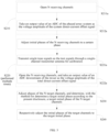
- The present disclosure provides a phase calibration method. As shown in
FIG. 4 , the phase calibration method includes the following operations S210 to S240. - At S210, generating a system direct-current offset signal of a phased array system corresponding to N target channels to be calibrated, and outputting a voltage amplitude of the system direct-current offset signal.
- At S220, adjusting initial phases of the N target channels, wherein each time the initial phases of the N target channels are adjusted to another phase value, test signals are provided for the N target channels so that a mixer downstream of a power combiner of the phased array system outputs a total direct-current offset signal, as well as a voltage amplitude of the total direct-current offset signal.
- At S230, determining, with the method for determining a target initial phase according to the present disclosure, a target initial phase of the N target channels.
- At S240, respectively adjusting the initial phases of the target channels to the target initial phase.
- According to the phase calibration method of the present disclosure, signals of the channels in the phased array system are each subjected to self-mixing in the mixer to obtain the target initial phase of each target channel, thereby simplifying the calibration process. In addition, since no additional calibration device is desired, no additional calibration deviation is introduced, and the calibration accuracy is thus improved.
- In the present disclosure, how to adjust the phase of each target channel in operation S220 is not particularly limited. Each channel in the phased array system corresponds to a phase shifter that may be configured to adjust the phase of each target channel.
- As described above, the target channel may be a receiving channel or a transmitting channel. The following describes the phase calibration method in the cases where the target channel is a receiving channel and where the target channel is a transmitting channel.
- When the target channel is a receiving channel, as shown in
FIG. 5 , operation S210 may include the following operations S211a to S212a. - At S211a, opening N receiving channels.
- At S212a, taking an output value of an ADC of the phased array system as the voltage amplitude of the system direct-current offset signal.
- The test signals are not particularly limited in the present disclosure. As an optional implementation, as shown in
FIG. 5 , operation S220 may include the following operations S221a to S222a. - At S221a, transmitting single tone signals as the test signals through a single-channel transmitter antenna for calibration.
- At S222a, opening the N receiving channels, and taking an output value of an ADC downstream of the mixer as the voltage amplitude of the total direct-current offset signal.
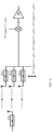
- The calibration method for receiving channels is further described in detail below with reference to
FIGs. 5 and6 . - At S211a, opening all receiving channels without any external input to the phased array system.
- At S212a, recording a voltage amplitude of the direct-current offset signal measured at an output end of the ADC at this time. This direct-current offset signal is the system direct-current offset signal. For convenience of distinguishing from the calibration of transmitting channels, the system direct-current offset signal is referred to herein as

- At S221a, transmitting single tone signals through a single-channel transmitter antenna for calibration so that the receiving channels RX 1, RX 2, RX 3, ..., RX n of the phased array system respectively receive the single tone signals in phase and with equal magnitudes.
- At S222a, finally superimposing amplifications of the channels at the power combiner. Since different receiving channels have different initial phases, the finally superimposed signal may be represented by the above formula (5):

- The formula (5) shows that the signal at the power combiner is a superposition of the signals received by the receiving channels after channel amplification and initial phase adjustment.
- The signal generated by mixing in the mixer may be expressed by the above formula (6):

- The formula (6) shows that based on the mixing principle of formula (2), the mixing of the output of the power combiner and the local oscillator signal of the mixer means multiplying a plurality of cosine signals by the local oscillator signal.
- After the high-frequency signal is filtered by the low-pass filter, the voltage amplitude of remaining direct-current offset signal is expressed by the following formula (7):

- The above formula shows that the received signal has the same frequency as the local oscillator signal, and shows the remaining difference frequency signal after the high-frequency signal is filtered out. The difference frequency signal in this case is a direct-current component which reaches a maximum value when initial phases of all cosine signals are the same as the initial phase of the local oscillator signal.
- The direct-current offset signal generated after the mixing in the mixer is superposed with the initial system direct-current offset signal, and then, the direct-current offset signal measured at the output end of the ADC is recorded as


- At S230, setting the optimization target to


- The formula (8) shows that the condition for the direct-current component generated by mixing reaches the maximum value is that initial phases of all receiving channels are the same as the initial phase of the local oscillator signal.
- Therefore, the relationship is ϕ 1 = ϕ 2=... ...=ϕ N=ϕ 0, thereby implementing phase calibration of each receiving channel in the phased array system, and ensuring that all receiving channels have a same initial phase.
- At S240, respectively adjusting the initial phase of each target channel to a corresponding target initial phase.
- When the target channel is a transmitting channel, as shown in
FIG. 7 , operation S210 may include the following operations S211b to S212b. - At S211b, opening a receiving channel for calibration.
- At S212b, taking an output value of an ADC of the phased array system as the voltage amplitude of the system direct-current offset signal.
- In the present disclosure, how to provide the test signals is not particularly limited. Optionally, single tone signals transmitted through a multi-channel transmitter antenna may be used as the test signals. Specifically, as shown in
FIG. 7 , operation S220 may include the following operations S221b to S222b. - At S221b, transmitting single tone signals as the test signals through a multi-channel transmitter antenna.
- At S222b, opening the receiving channel for calibration, and taking an output value of an ADC downstream of the mixer as the voltage amplitude of the total direct-current offset signal.
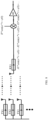
- The calibration method for transmitting channels is further described in detail below with reference to
FIGs. 7 and8 . - At S211b, opening the channels in the case where no external input is applied to the receiving channel for calibration.
- At S212b, recording a voltage amplitude of the direct-current offset signal measured at an output end of the ADC at this time as

- At S221b, transmitting single tone signals through a multi-channel transmitter antenna of the phased array system.
- In S222b, since different channels have different initial phases, the final superimposed signal at the input end of the mixer of the receiving channel for calibration is:

- The above formula shows that the signal before the mixer of the receiving channel for calibration is a superposition of signals from transmitting channels to be calibrated, which signals may have different amplitudes and initial phases, but have a same frequency.
- The signal generated after the mixing in the mixer is:

- The above formula shows that based on the mixing principle of formula (2), the mixing of the input of the mixer of the receiving channel for calibration and the local oscillator signal of the mixer means multiplying a plurality of cosine signals by the local oscillator signal.
- After the high-frequency signal is filtered by the low-pass filter, the remaining direct-current offset signal is:

- The above formula shows that the transmitted signals have the same frequency as the local oscillator signal of the receiving channel for calibration, and shows the remaining difference frequency signal after the high-frequency signal is filtered out in the receiving channel for calibration. The difference frequency signal in this case is a direct-current component which reaches a maximum value when initial phases of all cosine signals are the same as the initial phase of the local oscillator signal.
- The direct-current offset signal generated after the mixing in the mixer is superposed with the initial system direct-current offset signal, and then, the direct-current offset signal measured at the output end of the ADC is recorded as


- At S230, setting the optimization target to


- The formula (9) shows that the condition for the direct-current component generated by mixing reaches the maximum value is that initial phases of all transmitting channels are the same as the initial phase of the local oscillator signal.
- Therefore, the relationship is ϕ 1 = ϕ 2=... ...=ϕ N=ϕ 0, thereby implementing phase calibration of each transmitting channel in the phased array system, and ensuring that all transmitting channels have a same initial phase.
- At S240, respectively adjusting the initial phase of each target channel to a corresponding target initial phase.
- The phase calibration method of the present disclosure is described below taking the case where the number N of channels is 2 as an example.
- The phase calibration method for receiving channels is described in detail below with reference to
FIG. 5 and9 . - At S211a, opening all receiving channels without any external input to a dual channel phased array system.
- At S212a, recording a voltage amplitude of the direct-current offset signal measured at an output end of the ADC at this time as

- At S221a, transmitting single tone signals through a single-channel transmitter antenna for calibration so that the receiving channels RX 1 and RX 2 of the dual channel phased array system receive the single tone signals in phase and with equal magnitudes.
- At S222a, finally superimposing amplifications of the channels at the power combiner. Since different channels have different initial phases, the final superimposed signal is:

- The above formula shows that the signal at the power combiner is a superposition of the signals received by the receiving channels after channel amplification and initial phase adjustment.
- The signal generated after the mixing in the mixer is:

- The above formula shows that based on the mixing principle of formula (2), the mixing of the output of the power combiner and the local oscillator signal of the mixer means multiplying two cosine signals by the local oscillator signal.
- After the high-frequency signal is filtered by the low-pass filter, the remaining direct-current offset signal is:

- The above formula shows that the received signal has the same frequency as the local oscillator signal, and shows the remaining difference frequency signal after the high-frequency signal is filtered out. The difference frequency signal in this case is a direct-current component which reaches a maximum value when initial phases of the two cosine signals are both the same as the initial phase of the local oscillator signal.
- The direct-current offset signal generated after the mixing in the mixer is superposed with the initial system direct-current offset signal, and then, the direct-current offset signal measured at the output end of the ADC is recorded as


- At S230, setting the optimization target to

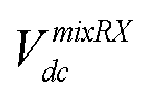


- The formula (10) shows that the condition for the direct-current component generated by mixing reaches the maximum value is that initial phases of the two receiving channels are both the same as the initial phase of the local oscillator signal.
- Therefore, the relationship is ϕ 1 = ϕ 2=ϕ 0, thereby implementing phase calibration of each receiving channel in the dual channel phased array system, and ensuring that all receiving channels have a same initial phase.
- At S240, adjusting initial phases of the two receiving channels to the phases determined in operation S230.
- The phase calibration method for receiving channels is described in detail below with reference to
FIG. 7 and10 . - At S211b, opening the channels in the case where no external input is applied to a receiving channel for calibration.
- At S212b, recording a voltage amplitude of the direct-current offset signal measured at an output end of the ADC at this time as

- At S221b, transmitting single tone signals through a dual channel transmitter antenna.
- In S222b, since different channels have different initial phases, the final superimposed signal at the input end of the mixer of the receiving channel for calibration is:

- The above formula shows that the signal before the mixer of the receiving channel for calibration is a superposition of signals from the two transmitting channels to be calibrated, which signals may have different amplitudes and initial phases, but have a same frequency.
- The signal generated after the mixing in the mixer is:

- The above formula shows that based on the mixing principle of formula (2), the mixing of the input of the mixer of the receiving channel for calibration and the local oscillator signal of the mixer means multiplying two cosine signals by the local oscillator signal.
- After the high-frequency signal is filtered by the low-pass filter, the remaining direct-current offset signal is:

- The above formula shows that the two transmitted signals have the same frequency as the local oscillator signal of the receiving channel for calibration, and shows the remaining difference frequency signal after the high-frequency signal is filtered out in the receiving channel for calibration. The difference frequency signal in this case is a direct-current component which reaches a maximum value when initial phases of the two cosine signals are both the same as the initial phase of the local oscillator signal.
- The direct-current offset signal generated after the mixing in the mixer is superposed with the initial system direct-current offset signal, and then, the direct-current offset signal measured at the output end of the ADC is recorded as
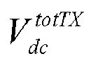

- At S230, setting the optimization target to


- The formula (11) shows that the condition for the direct-current component generated by mixing reaches the maximum value is that initial phases of the two transmitting channels are both the same as the initial phase of the local oscillator signal.
- Therefore, the relationship is ϕ 1 = ϕ 2=ϕ 0, thereby implementing phase calibration of each transmitting channel in the dual channel phased array system, and ensuring that all transmitting channels have a same initial phase.
- At S240, adjusting initial phases of the two transmitting channels to the phases determined in operation S230.
- The present disclosure provides an apparatus for determining a target initial phase, including: a memory module having a computer program stored thereon, and one or more processors which invoke the computer program to implement the method for determining a target initial phase according to the present disclosure.
- The apparatus for determining a target initial phase may further include a read/write (I/O) interface connected between the one or more processors and the memory module to enable information interaction between the one or more processors and the memory module.
- Each processor is a device with a data processing capability, including but not limited to a central processing unit (CPU) or the like; and the memory module is a device with a data storage capability, including but not limited toa random access memory (RAM, more specifically SDRAM, DDR, etc.), a read only memory (ROM), an electrically erasable programmable read only memory (EEPROM) or a flash memory (FLASH).
- The I/O interface, including but not limited to a data bus, is connected between the processors and the memory module to enable information interaction between the processors and the memory module.
- The processors, the memory module, and the I/O interface are interconnected via a bus, and thus are further connected to other components of the apparatus for determining a target initial phase.
- The present disclosure provides a computer-readable storage medium having a computer program stored thereon which, when invoked by a processor, causes the processor to implement the method for determining a target initial phase according to the present disclosure.
- Those of ordinary skill in the art will appreciate that all or some operations of the above described method, functional modules/units in the system and apparatus may be implemented as software, firmware, hardware, and suitable combinations thereof. In a hardware implementation, the division between the functional modules/units mentioned in the above description does not necessarily correspond to the division of physical components; for example, one physical component may have multiple functions, or one function or operation may be performed cooperatively by several physical components. Some or all physical components may be implemented as software executed by a processor, such as a CPU, a digital signal processor or microprocessor, or implemented as hardware, or implemented as an integrated circuit, such as an application specific integrated circuit. Such software may be distributed on a computer-readable medium which may include a computer storage medium (or non-transitory medium) and communication medium (or transitory medium). As is well known to those of ordinary skill in the art, the term computer storage medium includes volatile and nonvolatile, removable and non-removable medium implemented in any method or technology for storing information, such as computer-readable instructions, data structures, program modules or other data. A computer storage medium includes, but is not limited to, RAM, ROM, EEPROM, flash memory or other memory technology, CD-ROM, digital versatile disc (DVD) or other optical disc storage, magnetic cartridge, magnetic tape, magnetic disk storage or other magnetic storage devices, or may be any other medium used for storing the desired information and accessible by a computer. Moreover, it is well known to one of ordinary skill in the art that a communication medium typically includes a computer-readable instruction, a data structure, a program module, or other data in a modulated data signal, such as a carrier wave or other transport mechanism, and may include any information delivery medium.
- The present disclosure provides an antenna device, including: a phased array system; and a target initial phase determining apparatus according to the present disclosure.
- With the apparatus for determining a target initial phase, the phase calibration accuracy of each channel in the phased array system can be improved, thereby improving the beam forming performance of the antenna device.
- It should be understood that the above embodiments are merely exemplary embodiments for the purpose of illustrating the principle of the disclosure, and the disclosure is not limited thereto. Various modifications and improvements can be made by a person having ordinary skill in the art without departing from the spirit and essence of the disclosure. Accordingly, all of the modifications and improvements also fall into the protection scope of the disclosure.
Claims (13)
- A method for determining a target initial phase, comprising:acquiring a voltage amplitude of a system direct-current offset signal of a phased array system corresponding to N target channels to be calibrated;respectively acquiring voltage amplitudes of a total direct-current offset signal under different initial phases, wherein for any initial phase, the total direct-current offset signal is a total direct-current offset signal of an initial mixed signal output from a mixer downstream of a power combiner of the phased array system after test signals are provided for the N target channels; andcalculating voltage amplitudes of a mixed direct-current offset signal of the N target channels under the different initial phases, and taking an initial phase of the N target channels, when the voltage amplitude of the mixed direct-current offset signal reaches the maximum value, as a target initial phase of the N target channels;wherein the voltage amplitude of the mixed direct-current offset signal is calculated by:
 where
where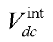

 N is the number of channels in the phased array system.
 - The method for determining a target initial phase according to claim 1, wherein each of the target channels is a receiving channel, and in the operation of acquiring the voltage amplitude of the system direct-current offset signal of the phased array system corresponding to the N target channels to be calibrated, the voltage amplitude of the system direct-current offset signal is an output value of an analog-to-digital converter downstream of the mixer after the N receiving channels are opened.
- The method for determining a target initial phase according to claim 2, wherein the test signals provided for the N target channels are single tone signals transmitted from a transmitter antenna of a single channel used for calibration, and
in the operation of respectively acquiring the voltage amplitudes of the total direct-current offset signal under different initial phases, the voltage amplitude of the total direct-current offset signal is an output value of the analog-to-digital converter after the N receiving channels are opened. - The method for determining a target initial phase according to claim 1, wherein each of the target channels is a transmitting channel, and in the operation of acquiring the voltage amplitude of the system direct-current offset signal of the phased array system corresponding to the N target channels to be calibrated, the voltage amplitude of the system direct-current offset signal is an output value of an analog-to-digital converter downstream of the mixer after a receiving channel for calibration is opened.
- The method for determining a target initial phase according to claim 4, wherein the test signals provided for the N target channels are single tone signals transmitted through a multi-channel transmitter antenna of the phased array system, and
in the operation of respectively acquiring the voltage amplitudes of the total direct-current offset signal under different initial phases, the voltage amplitude of the total direct-current offset signal is an output value of the analog-to-digital converter after the receiving channel for calibration is opened. - A phase calibration method, comprising:generating a system direct-current offset signal of a phased array system corresponding to N target channels to be calibrated, and outputting a voltage amplitude of the system direct-current offset signal;adjusting initial phases of the N target channels, wherein each time the initial phases of the N target channels are adjusted to another phase value, test signals are provided for the N target channels so that a mixer downstream of a power combiner of the phased array system outputs a total direct-current offset signal, as well as a voltage amplitude of the total direct-current offset signal;determining, according to the method for determining a target initial phase according to any one of claims 1 to 5, a target initial phase of the N target channels; andrespectively adjusting the initial phases of the target channels to the target initial phase.
- The phase calibration method according to claim 6, wherein each of the target channels is a receiving channel, and the operation of generating the system direct-current offset signal of the phased array system corresponding to the N target channels to be calibrated, and outputting the voltage amplitude of the system direct-current offset signal comprises:opening the N receiving channels; andtaking an output value of an analog-to-digital converter of the phased array system as the voltage amplitude of the system direct-current offset signal.
- The phase calibration method according to claim 7, wherein the operation of providing test signals for the N target channels so that the mixer downstream of the power combiner of the phased array system outputs the total direct-current offset signal, as well as the voltage amplitude of the total direct-current offset signal comprises:transmitting single tone signals as the test signals through a single-channel transmitter antenna for calibration; andopening the N receiving channels, and taking the output value of the analog-to-digital converter as the voltage amplitude of the total direct-current offset signal.
- The phase calibration method according to claim 6, wherein each of the target channels is a transmitting channel, and the operation of generating the system direct-current offset signal of the phased array system corresponding to the N target channels to be calibrated, and outputting the voltage amplitude of the system direct-current offset signal comprises:opening a receiving channel for calibration; andtaking an output value of an analog-to-digital converter of the phased array system as the voltage amplitude of the system direct-current offset signal.
- The phase calibration method according to claim 9, wherein the operation of providing test signals for the N target channels so that the mixer downstream of the power combiner of the phased array system outputs the total direct-current offset signal, as well as the voltage amplitude of the total direct-current offset signal comprises:transmitting single tone signals as the test signals through a multi-channel transmitter antenna; andopening the receiving channel for calibration, and taking an output value of an analog-to-digital converter downstream of the mixer as the voltage amplitude of the total direct-current offset signal.
- An apparatus for determining a target initial phase, comprising:a memory module having a computer program stored thereon, andone or more processors which invoke the computer program to implement the method for determining a target initial phase according to any one of claims 1 to 5.
- A computer-readable storage medium having a computer program stored thereon which, when invoked by a processor, causing the processor to implement the method for determining a target initial phase according to any one of claims 1 to 5.
- An antenna device, comprising:a phased array system; andthe apparatus for determining a target initial phase according to claim 11.
Applications Claiming Priority (2)
| Application Number | Priority Date | Filing Date | Title |
|---|---|---|---|
| CN202010618636.8A CN113872706B (en) | 2020-06-30 | 2020-06-30 | Phase determination method and device, phase calibration method, medium, and antenna device |
| PCT/CN2021/101208 WO2022001721A1 (en) | 2020-06-30 | 2021-06-21 | Phase determination method and apparatus, phase calibration method, medium, and antenna device |
Publications (2)
| Publication Number | Publication Date |
|---|---|
| EP4170936A1 true EP4170936A1 (en) | 2023-04-26 |
| EP4170936A4 EP4170936A4 (en) | 2024-07-31 |
Family
ID=78981655
Family Applications (1)
| Application Number | Title | Priority Date | Filing Date |
|---|---|---|---|
| EP21832242.8A Pending EP4170936A4 (en) | 2020-06-30 | 2021-06-21 | Phase determination method and apparatus, phase calibration method, medium, and antenna device |
Country Status (5)
| Country | Link |
|---|---|
| US (1) | US12267115B2 (en) |
| EP (1) | EP4170936A4 (en) |
| KR (1) | KR102778634B1 (en) |
| CN (1) | CN113872706B (en) |
| WO (1) | WO2022001721A1 (en) |
Families Citing this family (5)
| Publication number | Priority date | Publication date | Assignee | Title |
|---|---|---|---|---|
| CN114725682B (en) * | 2022-04-19 | 2023-08-01 | 广州程星通信科技有限公司 | Phased array beam pointing design method, system, device and storage medium |
| CN115144649B (en) * | 2022-06-30 | 2024-06-14 | 成都通量科技有限公司 | A self-detection circuit based on power detector |
| CN115313045A (en) * | 2022-07-14 | 2022-11-08 | 广州程星通信科技有限公司 | Method, system, device and storage medium for amplitude weighting of phased array array |
| CN117375737B (en) * | 2023-10-31 | 2025-07-18 | 复旦大学 | Phased array transmitting link-oriented power detection system |
| CN118625573B (en) * | 2024-08-15 | 2024-11-22 | 中国科学院长春光学精密机械与物理研究所 | Initial phase calibration method of optical phased array |
Family Cites Families (17)
| Publication number | Priority date | Publication date | Assignee | Title |
|---|---|---|---|---|
| CA2195925A1 (en) * | 1997-01-24 | 1998-07-24 | Peter R. Moosbrugger | Fmcw radar with angular position detection |
| US7203614B2 (en) * | 2005-07-29 | 2007-04-10 | Mediatek Inc. | Method and calibration system for IQ DC offset and imbalance calibration by utilizing analytic formulas to quickly determined desired compensation values |
| US7742747B2 (en) * | 2007-01-25 | 2010-06-22 | Icera Canada ULC | Automatic IIP2 calibration architecture |
| WO2009075144A1 (en) * | 2007-12-10 | 2009-06-18 | Nec Corporation | Wireless communication device and dc offset adjustment method |
| IL188507A (en) | 2007-12-31 | 2012-06-28 | Elta Systems Ltd | Phased array antenna having integral calibration network and method for measuring calibration ratio thereof |
| CN101483274B (en) * | 2009-02-24 | 2012-06-13 | 中国航天科技集团公司第五研究院第五○四研究所 | External calibration method for phase variable power detecting array antenna |
| JP5104938B2 (en) * | 2010-12-09 | 2012-12-19 | 株式会社デンソー | Phased array antenna phase calibration method and phased array antenna |
| JP5246250B2 (en) * | 2010-12-09 | 2013-07-24 | 株式会社デンソー | Phased array antenna phase calibration method and phased array antenna |
| US8913694B2 (en) * | 2012-12-05 | 2014-12-16 | Mstar Semiconductor, Inc. | Fast LO leakage calibration of direct up-conversion transmitters using three measurements |
| KR101963639B1 (en) * | 2012-12-12 | 2019-03-29 | 삼성전자주식회사 | Apparatus and method for dc offset calibration in signal transmission apparatus |
| JP6862670B2 (en) * | 2016-04-01 | 2021-04-21 | 富士通株式会社 | How to correct electronic circuits, radar devices, and radar transmission channels |
| WO2017185315A1 (en) * | 2016-04-29 | 2017-11-02 | Teradyne (Shanghai) Co., Ltd. | Method and test system for providing accurate analog signals |
| CN113242046A (en) * | 2016-11-25 | 2021-08-10 | 华为技术有限公司 | Polarized phased array transmitter and mobile terminal |
| KR101785980B1 (en) * | 2016-12-26 | 2017-10-16 | 광운대학교 산학협력단 | Apparatus of phase and amplitude calibration to phased array antenna |
| KR102457109B1 (en) | 2017-08-23 | 2022-10-20 | 삼성전자주식회사 | Apparatus and method for calibrating phased array antenna |
| CN108234037B (en) * | 2017-12-29 | 2021-07-20 | 鹤壁天海电子信息系统有限公司 | Phase calibration method and circuit |
| CN109361064B (en) | 2018-11-12 | 2020-04-24 | 北京航空航天大学 | Intelligent phase shifter system with reconfigurable scale |
-
2020
- 2020-06-30 CN CN202010618636.8A patent/CN113872706B/en active Active
-
2021
- 2021-06-21 US US18/013,937 patent/US12267115B2/en active Active
- 2021-06-21 EP EP21832242.8A patent/EP4170936A4/en active Pending
- 2021-06-21 KR KR1020237001861A patent/KR102778634B1/en active Active
- 2021-06-21 WO PCT/CN2021/101208 patent/WO2022001721A1/en not_active Ceased
Also Published As
| Publication number | Publication date |
|---|---|
| CN113872706A (en) | 2021-12-31 |
| WO2022001721A1 (en) | 2022-01-06 |
| KR20230025462A (en) | 2023-02-21 |
| EP4170936A4 (en) | 2024-07-31 |
| US20230299857A1 (en) | 2023-09-21 |
| KR102778634B1 (en) | 2025-03-07 |
| CN113872706B (en) | 2025-02-07 |
| US12267115B2 (en) | 2025-04-01 |
Similar Documents
| Publication | Publication Date | Title |
|---|---|---|
| US12267115B2 (en) | Phase determination method and apparatus, phase calibration method, medium and antenna device | |
| US9584175B2 (en) | Radio frequency transceiver loopback testing | |
| US11460542B2 (en) | Phase rotator calibration of a multichannel radar transmitter | |
| US7982663B2 (en) | Digital signal processor | |
| US11152964B2 (en) | Signal transmitter device and calibration method | |
| US10509106B2 (en) | Method for calibrating a radar system | |
| US9281907B2 (en) | Quadrature error correction using polynomial models in tone calibration | |
| US10374643B2 (en) | Transmitter with compensating mechanism of pulling effect | |
| CN119154971A (en) | Calibration link, signal receiving link, electromagnetic wave device and integrated circuit | |
| US8064863B1 (en) | Image rejection calibration | |
| KR102313253B1 (en) | Radio frequency device and corresponding method | |
| US10530338B2 (en) | Phase shift precision calibration circuitry, vector sum phase shifter, and wireless communication device | |
| EP4064575B1 (en) | Radio frequency receiving link and radio frequency transceiving device | |
| US11506749B2 (en) | Apparatus and method for adjusting a suppression signal for suppressing an RF interference signal | |
| US20050152481A1 (en) | Method and apparatus of iq mismatch calibration | |
| US20070185947A1 (en) | Frequency synthesizer | |
| US8325794B2 (en) | Apparatus and method for calibrating IQ mismatch | |
| US10230408B2 (en) | Measurement receiver harmonic distortion cancellation | |
| CN109155611A (en) | Inhibit the method and device thereof of local oscillator leakage in microwave chip | |
| US9148103B2 (en) | Gain measurement circuit, gain measurement method, and communication apparatus | |
| US20190173694A1 (en) | Signal transmitter device, detection circuit, and signal detection method thereof | |
| US20120170696A1 (en) | Receiver | |
| EP3796041B1 (en) | Distance measuring apparatus and distance measuring system | |
| US10931316B2 (en) | Radio frequency transceiver | |
| US20090046814A1 (en) | In-phase signal and quadrature signal generator of multi-port network |
Legal Events
| Date | Code | Title | Description |
|---|---|---|---|
| STAA | Information on the status of an ep patent application or granted ep patent |
Free format text: STATUS: THE INTERNATIONAL PUBLICATION HAS BEEN MADE |
|
| PUAI | Public reference made under article 153(3) epc to a published international application that has entered the european phase |
Free format text: ORIGINAL CODE: 0009012 |
|
| STAA | Information on the status of an ep patent application or granted ep patent |
Free format text: STATUS: REQUEST FOR EXAMINATION WAS MADE |
|
| 17P | Request for examination filed |
Effective date: 20230117 |
|
| AK | Designated contracting states |
Kind code of ref document: A1 Designated state(s): AL AT BE BG CH CY CZ DE DK EE ES FI FR GB GR HR HU IE IS IT LI LT LU LV MC MK MT NL NO PL PT RO RS SE SI SK SM TR |
|
| DAV | Request for validation of the european patent (deleted) | ||
| DAX | Request for extension of the european patent (deleted) | ||
| A4 | Supplementary search report drawn up and despatched |
Effective date: 20240701 |
|
| RIC1 | Information provided on ipc code assigned before grant |
Ipc: G01R 21/06 20060101ALI20240625BHEP Ipc: H04B 17/21 20150101ALI20240625BHEP Ipc: H04B 17/10 20150101ALI20240625BHEP Ipc: H04B 17/00 20150101ALI20240625BHEP Ipc: H01Q 3/26 20060101ALI20240625BHEP Ipc: H04B 17/12 20150101AFI20240625BHEP |
|
| RAP3 | Party data changed (applicant data changed or rights of an application transferred) |
Owner name: SANECHIPS TECHNOLOGY CO., LTD. |