EP4170780A1 - Cell, battery, manufacturing method for cell, and electronic device - Google Patents
Cell, battery, manufacturing method for cell, and electronic device Download PDFInfo
- Publication number
- EP4170780A1 EP4170780A1 EP21870537.4A EP21870537A EP4170780A1 EP 4170780 A1 EP4170780 A1 EP 4170780A1 EP 21870537 A EP21870537 A EP 21870537A EP 4170780 A1 EP4170780 A1 EP 4170780A1
- Authority
- EP
- European Patent Office
- Prior art keywords
- tab
- area
- bending
- cell
- sealing
- Prior art date
- Legal status (The legal status is an assumption and is not a legal conclusion. Google has not performed a legal analysis and makes no representation as to the accuracy of the status listed.)
- Pending
Links
Images


Classifications
-
- H—ELECTRICITY
- H01—ELECTRIC ELEMENTS
- H01M—PROCESSES OR MEANS, e.g. BATTERIES, FOR THE DIRECT CONVERSION OF CHEMICAL ENERGY INTO ELECTRICAL ENERGY
- H01M50/00—Constructional details or processes of manufacture of the non-active parts of electrochemical cells other than fuel cells, e.g. hybrid cells
- H01M50/10—Primary casings; Jackets or wrappings
- H01M50/183—Sealing members
- H01M50/184—Sealing members characterised by their shape or structure
-
- H—ELECTRICITY
- H01—ELECTRIC ELEMENTS
- H01M—PROCESSES OR MEANS, e.g. BATTERIES, FOR THE DIRECT CONVERSION OF CHEMICAL ENERGY INTO ELECTRICAL ENERGY
- H01M50/00—Constructional details or processes of manufacture of the non-active parts of electrochemical cells other than fuel cells, e.g. hybrid cells
- H01M50/10—Primary casings; Jackets or wrappings
- H01M50/102—Primary casings; Jackets or wrappings characterised by their shape or physical structure
- H01M50/103—Primary casings; Jackets or wrappings characterised by their shape or physical structure prismatic or rectangular
-
- H—ELECTRICITY
- H01—ELECTRIC ELEMENTS
- H01M—PROCESSES OR MEANS, e.g. BATTERIES, FOR THE DIRECT CONVERSION OF CHEMICAL ENERGY INTO ELECTRICAL ENERGY
- H01M10/00—Secondary cells; Manufacture thereof
- H01M10/04—Construction or manufacture in general
-
- H—ELECTRICITY
- H01—ELECTRIC ELEMENTS
- H01M—PROCESSES OR MEANS, e.g. BATTERIES, FOR THE DIRECT CONVERSION OF CHEMICAL ENERGY INTO ELECTRICAL ENERGY
- H01M50/00—Constructional details or processes of manufacture of the non-active parts of electrochemical cells other than fuel cells, e.g. hybrid cells
- H01M50/10—Primary casings; Jackets or wrappings
- H01M50/183—Sealing members
- H01M50/186—Sealing members characterised by the disposition of the sealing members
- H01M50/188—Sealing members characterised by the disposition of the sealing members the sealing members being arranged between the lid and terminal
-
- H—ELECTRICITY
- H01—ELECTRIC ELEMENTS
- H01M—PROCESSES OR MEANS, e.g. BATTERIES, FOR THE DIRECT CONVERSION OF CHEMICAL ENERGY INTO ELECTRICAL ENERGY
- H01M50/00—Constructional details or processes of manufacture of the non-active parts of electrochemical cells other than fuel cells, e.g. hybrid cells
- H01M50/50—Current conducting connections for cells or batteries
- H01M50/502—Interconnectors for connecting terminals of adjacent batteries; Interconnectors for connecting cells outside a battery casing
- H01M50/519—Interconnectors for connecting terminals of adjacent batteries; Interconnectors for connecting cells outside a battery casing comprising printed circuit boards [PCB]
-
- H—ELECTRICITY
- H01—ELECTRIC ELEMENTS
- H01M—PROCESSES OR MEANS, e.g. BATTERIES, FOR THE DIRECT CONVERSION OF CHEMICAL ENERGY INTO ELECTRICAL ENERGY
- H01M50/00—Constructional details or processes of manufacture of the non-active parts of electrochemical cells other than fuel cells, e.g. hybrid cells
- H01M50/50—Current conducting connections for cells or batteries
- H01M50/528—Fixed electrical connections, i.e. not intended for disconnection
-
- H—ELECTRICITY
- H01—ELECTRIC ELEMENTS
- H01M—PROCESSES OR MEANS, e.g. BATTERIES, FOR THE DIRECT CONVERSION OF CHEMICAL ENERGY INTO ELECTRICAL ENERGY
- H01M50/00—Constructional details or processes of manufacture of the non-active parts of electrochemical cells other than fuel cells, e.g. hybrid cells
- H01M50/50—Current conducting connections for cells or batteries
- H01M50/531—Electrode connections inside a battery casing
- H01M50/536—Electrode connections inside a battery casing characterised by the method of fixing the leads to the electrodes, e.g. by welding
-
- H—ELECTRICITY
- H01—ELECTRIC ELEMENTS
- H01M—PROCESSES OR MEANS, e.g. BATTERIES, FOR THE DIRECT CONVERSION OF CHEMICAL ENERGY INTO ELECTRICAL ENERGY
- H01M50/00—Constructional details or processes of manufacture of the non-active parts of electrochemical cells other than fuel cells, e.g. hybrid cells
- H01M50/50—Current conducting connections for cells or batteries
- H01M50/543—Terminals
- H01M50/547—Terminals characterised by the disposition of the terminals on the cells
- H01M50/55—Terminals characterised by the disposition of the terminals on the cells on the same side of the cell
-
- H—ELECTRICITY
- H01—ELECTRIC ELEMENTS
- H01M—PROCESSES OR MEANS, e.g. BATTERIES, FOR THE DIRECT CONVERSION OF CHEMICAL ENERGY INTO ELECTRICAL ENERGY
- H01M50/00—Constructional details or processes of manufacture of the non-active parts of electrochemical cells other than fuel cells, e.g. hybrid cells
- H01M50/50—Current conducting connections for cells or batteries
- H01M50/543—Terminals
- H01M50/552—Terminals characterised by their shape
- H01M50/553—Terminals adapted for prismatic, pouch or rectangular cells
-
- H—ELECTRICITY
- H01—ELECTRIC ELEMENTS
- H01M—PROCESSES OR MEANS, e.g. BATTERIES, FOR THE DIRECT CONVERSION OF CHEMICAL ENERGY INTO ELECTRICAL ENERGY
- H01M50/00—Constructional details or processes of manufacture of the non-active parts of electrochemical cells other than fuel cells, e.g. hybrid cells
- H01M50/10—Primary casings; Jackets or wrappings
- H01M50/172—Arrangements of electric connectors penetrating the casing
- H01M50/174—Arrangements of electric connectors penetrating the casing adapted for the shape of the cells
- H01M50/178—Arrangements of electric connectors penetrating the casing adapted for the shape of the cells for pouch or flexible bag cells
-
- H—ELECTRICITY
- H01—ELECTRIC ELEMENTS
- H01M—PROCESSES OR MEANS, e.g. BATTERIES, FOR THE DIRECT CONVERSION OF CHEMICAL ENERGY INTO ELECTRICAL ENERGY
- H01M50/00—Constructional details or processes of manufacture of the non-active parts of electrochemical cells other than fuel cells, e.g. hybrid cells
- H01M50/50—Current conducting connections for cells or batteries
- H01M50/543—Terminals
- H01M50/552—Terminals characterised by their shape
- H01M50/553—Terminals adapted for prismatic, pouch or rectangular cells
- H01M50/557—Plate-shaped terminals
-
- Y—GENERAL TAGGING OF NEW TECHNOLOGICAL DEVELOPMENTS; GENERAL TAGGING OF CROSS-SECTIONAL TECHNOLOGIES SPANNING OVER SEVERAL SECTIONS OF THE IPC; TECHNICAL SUBJECTS COVERED BY FORMER USPC CROSS-REFERENCE ART COLLECTIONS [XRACs] AND DIGESTS
- Y02—TECHNOLOGIES OR APPLICATIONS FOR MITIGATION OR ADAPTATION AGAINST CLIMATE CHANGE
- Y02E—REDUCTION OF GREENHOUSE GAS [GHG] EMISSIONS, RELATED TO ENERGY GENERATION, TRANSMISSION OR DISTRIBUTION
- Y02E60/00—Enabling technologies; Technologies with a potential or indirect contribution to GHG emissions mitigation
- Y02E60/10—Energy storage using batteries
-
- Y—GENERAL TAGGING OF NEW TECHNOLOGICAL DEVELOPMENTS; GENERAL TAGGING OF CROSS-SECTIONAL TECHNOLOGIES SPANNING OVER SEVERAL SECTIONS OF THE IPC; TECHNICAL SUBJECTS COVERED BY FORMER USPC CROSS-REFERENCE ART COLLECTIONS [XRACs] AND DIGESTS
- Y02—TECHNOLOGIES OR APPLICATIONS FOR MITIGATION OR ADAPTATION AGAINST CLIMATE CHANGE
- Y02P—CLIMATE CHANGE MITIGATION TECHNOLOGIES IN THE PRODUCTION OR PROCESSING OF GOODS
- Y02P70/00—Climate change mitigation technologies in the production process for final industrial or consumer products
- Y02P70/50—Manufacturing or production processes characterised by the final manufactured product
Definitions
- the present application relates to the field of electrochemical technology, in particular to a cell, a battery, a manufacturing method of a cell, and an electronic device.
- top sealing bending batteries are one of popular batteries currently.
- a top sealing of a battery is bent and fixed to one end face of the battery. Accordingly, a tab of the battery is also bent to facilitate electrical connection to the circuit board.
- a sealant is arranged between the tab and the top sealing, and in order to ensure a sealing effect of the top sealing at an extended position of the tab and avoid the tab contacting an exposed aluminum layer of the top sealing, the sealant will generally protrude a certain length from the top sealing.
- the length of the sealant protruding from the top sealing is often more than 1mm. Due to a high hardness of the sealant, it is not only difficult to be bent, but also occupies a large length in a length direction of the battery after bending, resulting in a waste of space in the length direction of the battery, which is not conducive to reducing a packaging space of the cell and improving the battery capacity.
- Embodiments of the present application provide a cell, a battery, a manufacturing method of a cell, and an electronic device, which reduces a bending difficulty of sealant, and reduces a length of the sealant after bending occupied in the length direction of the battery.
- an embodiment of the present application provides a cell, comprising: a shell, an electrode assembly, a tab, and a sealant;
- the shell comprises a main body and a top sealing, the main body comprises a bottom surface, a side surface and a top surface, the side surface is connected with the bottom surface and the top surface, and the top sealing is connected to the top surface and is bent towards the top surface;
- the electrode assembly is housed in the main body; one end of the tab is electrically connected to the electrode assembly, and the other end of the tab extends out of the top sealing;
- the sealant is located between the tab and the top sealing;
- the sealant comprises an exposed portion extending out of the top sealing, the exposed portion is provided with a bending line, the bending line is on the sealant, and perpendicular to an extension direction of the tab.
- the bending line is arranged opposite to the top sealing.
- the bending line can reduce the bending difficulty of the sealant, so that the length of the exposed portion after bending in the length direction of the cell can be reduced, which is conducive to improving the capacity of the cell.
- a stress required for bending the sealant at the bending line is smaller than that required for bending the sealant at other positions, which facilitates the bending of the sealant.
- the exposed portion is provided with an avoidance area and/or a thinning area, and the avoidance area and/or the thinning area is provided for bending of the tab.
- the avoidance area and/or the thinning area forms the bending line on the sealant.
- the exposed portion comprises a first part and a second part which are arranged oppositely along an extension direction of the tab, and the bending line is arranged between the first part and the second part.
- the second part can increase an area of the tab covered by the sealant, and reduces an exposed part of the tab, which is conducive to the protection of the tab.
- the avoidance area and/or the thinning area is continuously distributed, on the exposed portion, perpendicular to the extension direction of the tab.
- the avoidance area and/or the thinning area is continuously distributed between the first bending area and the second bending area, which can be regarded as the avoidance area and/or the thinning area passing through the bending area along a third direction (e.g., the third direction is perpendicular to the extension direction of the tab), and it is conducive to reducing preparation difficulty of the avoidance area and/or the thinning area.
- the avoidance areas and/or the thinning areas are distributed at intervals, on the exposed portion, perpendicular to the extension direction of the tab.
- the first part and the second part are still connected and are not disconnected, which is conducive to the structural strength of the exposed portion and the protection of the tab.
- the risk of electrical contact between the tab and the aluminum-plastic film at a cut opening on of the top sealing can be reduced, so as to reduce the safety risk caused by short circuit.
- the exposed portion comprises a first part and a second part which are arranged oppositely along an extension direction of the tab; along a direction perpendicular to extension direction of the tab, an length of the first part is less than that of the second part on at least one side of the tab, which can reduce the risk of puncturing the packaging tape by burrs or the like at the fracture (i.e. the edge of the bending line) of the exposed portion after bending.
- a difference between the lengths of the second part and the first part is D 0 , and 0.5mm ⁇ D 0 ⁇ 3.0mm.
- a distance between the avoidance area and/or the thinning area and the top sealing is W 0 , and 0.2mm ⁇ W 0 ⁇ 1.0mm.
- W 0 0.5mm, which facilitates bending of the sealant.
- a height of the exposed portion is H 0 , and 0.2mm ⁇ H 0 ⁇ 3.0mm.
- the length of the top sealing is H 2 , and 1.0mm ⁇ H 2 ⁇ 4.0mm.
- the bending line is arranged on a side of the exposed portion located at the tab. That is, on one side of the tab, the sealant is provided with a bending line, while on the other side of the tab, the sealant is not provided with bending line, which can reduce a bending difficulty of the sealant.
- the bending line is provided on a side of the bending area facing away from the top sealing, after bending, the sealant facing the top sealing can reduce the risk of electrical contact between the tab and the aluminum-plastic film at a cut opening of the top sealing, so as to reduce the safety risk caused by short circuit.
- an embodiment of the present application provides a manufacturing method of a cell, used to manufacture any one of the above-mentioned cells, wherein the method comprises: placing the cell packing with a sealant on a positioning device for positioning, wherein the sealant is located between the tab and the top sealing of the cell; and using a laser to cut the sealant along a width direction of the tab to form a bending line on the sealant, wherein the bending line comprises an avoidance area and/or a thinning area, and the avoidance area and/or the thinning area is provided for bending of the tab.
- the sealant is cut with a continuous laser having a first energy to form avoidance areas being continuously distributed on the sealant.
- the sealant is cut with an intermittent laser having a first energy to form avoidance areas being distributed at intervals on the sealant.
- the sealant is cut with a laser having a second energy to form thinning areas on the sealant, and the second energy is less than the first energy.
- the laser is a carbon dioxide laser
- a pulse width of the laser is 10ns to 500ns
- a frequency is 500 KHz to 2000 KHz
- a moving rate of the laser is 20mm/s to 50mm/s.
- an embodiment of the present application provides a battery, comprising: a shell, an electrode assembly, a tab, a sealant, and a circuit board.
- the shell comprises a main body and a top sealing, the main body comprises a bottom surface, a side surface and a top surface, the side surface is connected with the bottom surface and the top surface, and the top sealing is connected to the top surface and is bent towards the top surface;
- the electrode assembly is housed in the main body; one end of the tab is electrically connected to the electrode assembly, and the other end of the tab extends out of the top sealing;
- the circuit board is arranged on a side of the top sealing facing away from the electrode assembly and electrically connected with the tab of the cell;
- the sealant is located between the tab and the top sealing and comprises an exposed portion extending out of the top sealing, the exposed portion is provided with a bending area, and the tab is arranged to bend in the bending area.
- the exposed portion of the sealant can be bent with the bending of the tab, and the length
- the exposed portion comprises a first sub part and a second sub part, the first sub part is connected with the top sealing and extends along a first direction, the second sub part is connected with the circuit board and extends along an opposite direction of the first direction, and the bending area connects the first sub part and the second sub part.
- a stress required for bending the sealant at the bending area is smaller than that required for bending the sealant at other positions.
- the bending area is provided with an avoidance areas and/or a thinning area.
- the bending area comprises a first bending area and a second bending area which are arranged oppositely along a second direction, and the bending line is arranged between the first bending area and the second bending area.
- avoidance areas and/or thinning areas are distributed continuously on the bending area along a third direction, and the third direction is perpendicular to the first direction and the second direction.
- the avoidance areas and/or the thinning areas are distributed continuously between the first bending area and the second bending area, which can be regarded as the avoidance areas and/or the thinning areas passing through the bending area along a third direction, which is conducive to reducing preparation difficulty of the avoidance area and/or the thinning area.
- the avoidance areas and/or the thinning areas are distributed at intervals on the bending area along a third direction, and the third direction is perpendicular to the first direction and the second direction.
- the first bending area and the second bending area are still connected and are not disconnected, which is conducive to improve the structural strength of the bending area, protect the tab, and reduce the risk of puncturing the packaging tape by burrs or the like at the fracture (i.e. the edge of the bending line) of the first bending area and the second bending area.
- the packaging tape is used to package and protect the head structure of the cell so as to, for example, electrically insulate the head structure from the outside, or the like.
- the bending area comprises a first bending area and a second bending area which are arranged oppositely along a second direction.
- an length of the first bending area is less than that of the second bending area on at least one side of the tab.
- the third direction is perpendicular to the first direction and the second direction.
- the risk of puncturing the packaging tape by burrs or the like at the fracture (i.e. the edge of the bending line) of the first bending area can be reduced.
- a difference between the lengths of the second bending area and the first bending area is D 0 , and 0.5mm ⁇ D 0 ⁇ 3.0mm.
- a bending angle of the bending area is ⁇ 0 , and 60° ⁇ 0 ⁇ 120°.
- a radius of curvature of the first bending area is R 1
- a radius of curvature of the second bending area is R 2
- an adhesive part is arranged between the top sealing and the circuit board, the adhesive part is configured to insulate and fix the circuit board on the top sealing, which can reduce the risk of electrical contact between the circuit board and the aluminum-plastic film (e.g., the aluminum-plastic film exposed at the fracture) of the top sealing, and reduce the length in the length direction of the battery.
- the adhesive part comprises at least one of double-sided adhesive, foam, hot-melt adhesive and silica gel.
- an embodiment of the present application provides a cell, comprising: a shell, an electrode assembly, a tab, and a sealant.
- the shell comprises a main body and a top sealing
- the main body comprises a bottom surface, a side surface and a top surface
- the side surface is connected with the bottom surface and the top surface
- the top sealing is connected to the top surface and is bent towards the top surface.
- the electrode assembly is housed in the main body.
- One end of the tab is electrically connected to the electrode assembly, and the other end of the tab extends out of the top sealing.
- the sealant is located between the tab and the top sealing.
- the shell further comprises a side sealing, the side sealing is connected to the side surface and bent towards the side surface, the top sealing is connected with the side sealing, an end of the side sealing away from the top surface has a first side, an end of the top sealing away from the top surface has a second side, an included angle between the first side and the second side is ⁇ , and 5° ⁇ 60°, and an included angle between the second side and the top surface is ⁇ ', and 60° ⁇ ' ⁇ 120°.
- an opening length of the included angle between the first side and the second side is L 0 , and 1.0mm ⁇ L 0 ⁇ 8.0mm.
- a height of the first side protruding from the top surface is H 1 , and 1.0mm ⁇ H 1 ⁇ 4.0mm.
- a thickness of the aluminum-plastic film of the top sealing and the side sealing is 67 ⁇ m to 150 ⁇ m, preferably, 86 ⁇ m to 115 ⁇ m, which is conductive to the bending of the top sealing and the side sealing.
- the cell further comprises a thermistor, and the thermistor can be arranged in the included angle of the first side and the second side.
- the thermistor is configured to prevent the cell from working at a too high temperature.
- the included angle of the first side and the second side is filled with a filler, and the filler is used to fix the folding angle of the first side and the second side.
- the filler is glue.
- an embodiment of the present application provides a battery, comprising a circuit board and any one of the above-mentioned cells, wherein the circuit board and the tab of the cell are electrically connected.
- the shell comprises two side sealings which are arranged oppositely, the circuit board is arranged between the two side sealings, and on the top sealing, and both ends of the circuit board are arranged opposite to the corresponding side sealings. It can not only reduce the extrusion of both ends of the circuit board to the side sealing, but also reduce the risk of damage to the side sealing due to collision.
- a distance between either end of the circuit board and the corresponding side sealing is W 1 , and 2.0mm ⁇ W 1 ⁇ 8.0mm.
- an adhesive part is arranged between the top sealing and the circuit board, the adhesive part is configured to insulate and fix the circuit board on the top sealing, which can reduce the risk of electrical contact between the circuit board and the aluminum-plastic film (e.g., the aluminum-plastic film exposed at the fracture) of the top sealing, and reduce the length in the length direction of the battery.
- the adhesive part comprises at least one of double-sided adhesive, foam, hot-melt adhesive and silica gel.
- an embodiment of the present application provides a manufacturing method of a cell, used to manufacture any one of the above-mentioned cells, wherein the method comprises: placing the cell in a positioning fixture for positioning, wherein the cell comprises a main body, a top sealing and a side sealing, the main body comprises a bottom surface, a side surface and a top surface, the side surface is connected with the bottom surface and the top surface, the top sealing is connected to the top surface, the side sealing is connected to the side surface, the top sealing is connected to the side sealing, an end of the side sealing away from the top surface has a first side, and an end of the top sealing away from the top surface has a second side; bending the side sealing towards the side surface; and bending the top sealing towards the top surface, and an included angle between the first side and the second side is ⁇ , and 5° ⁇ 60°, an included angle between the second side and the top surface is ⁇ ', and 60° ⁇ ' ⁇ 120°.
- an embodiment of the present application provides an electronic device, comprising a load and any one of the above-mentioned cells or batteries, wherein the cell or battery is configured to supply power to the load.
- the exposed portion of the sealant is provided with a bending line, and the exposed portion can be bent along the bending line, and the length in the length direction of the cell after being bent can be reduced, which is conducive to reducing the packaging space of the cell and improving the capacity of the cell.
- an exposed portion of sealant is provided with a bending area, and the tab is arranged to bend in the bending area, that is, the exposed portion of the sealant can be bent with the bending of the tab.
- the exposed portion of the sealant can not only protect the bending area of the tab and a part of the tab extending towards the circuit board, but also reduce the length of the cell, which is conducive to reducing the packaging space required by the cell and improving the capacity of the cell.
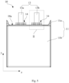
- a cell 10 of this embodiment comprises a shell 11, an electrode assembly (not shown), a tab 13, and a sealant 14.
- the shell 11 is surrounded to form a shape of the cell 10 and can also be configured to define an appearance of the cell 10.
- the shell 11 comprises a top sealing 11a, a main body 11b and a side sealing 11c.
- the electrode assembly is arranged in the main body 11b.
- the top sealing 11a and the tab 13 extend from a first end face of the main body 11b.
- the first end face of the main body 11b can be regarded as a first end face 10a of the cell 10, which will be described hereinafter as an example.
- the main body 11b is formed with a housing cavity, internal components of the cell 10 (such as electrode assembly and electrolyte) are built in the housing cavity, and the shell 11 is configured to protect the internal components, so as to improve the protection effect and safety.
- the main body 11b comprises a bottom surface 11b1, a side surface 11b2 and a top surface 11b3.
- the bottom surface 11b1 and the top surface 11b3 are arranged opposite to each other.
- the side surface 11b2 is connected with the bottom surface 11b1 and the top surface 11b3.
- the top sealing 11a and the side sealing 11c are formed by packaging the shell 11 after the electrode assembly is housed in the main body 11b.
- the top sealing 11a is connected with the top surface 11b3, and the side sealing 11c is connected with the side surface 11b2.
- the top sealing 11a is configured to realize sealing of the shell 11, so as to avoid the leakage of electrolyte from the first end face 10a, and the entry of impurities such as water and oxygen outside the shell 11 into the shell 11 from the first end face 10a.
- the top sealing 11a also seals an extending area of the tab 13 for sealing a joint between the shell 11 and the tab 13.
- the side sealing 11c is bent towards the side surface 11b2, and the top sealing 11a is bent towards the top surface 11b3.
- the width and length of the cell 10 are reduced, so as to meet size requirements of external electrical device and expand an application range.
- the side sealing 11c and the top sealing 11a are relatively weak components in the cell 10, by bending the side sealing 11c and the top sealing 11a towards the main body 11b of the shell 11, the side sealing 11c and the top sealing 11a are not easy to be damaged due to collision and other reasons, so that a service life of the electric core 10 provided in the embodiment of the present application is long.
- the top sealing 11a is a structure protruding from the main portion 11b of the cell 10. As shown in Fig. 1 , the top sealing 11a does not extend along a second direction y, but bends towards the first end face 10a and is fixed to the first end face 10a, so as to reduce an overall length of the cell 10.
- the second direction y is the length direction of the cell 10. It should be understood that in the cell 10, referring to Fig. 2 , the top sealing 11a can also extend along the second direction y without being bent, and at this time, the tab is not bent, either, and an extension direction of the tab 13 is the second direction y.
- a thickness direction of the cell 10 can be a first direction x
- a width direction of the tab 13 can be a third direction z
- two of the first direction x, the second direction y and the third direction z are perpendicular.
- the so-called perpendicularity in the description of the present application does not require that an included angle between the two must be 90°, instead, a deviation of ⁇ 10° is allowed, that is, the so-called perpendicularity can be understood as the included angle between any two directions is 80° to 100°.
- the top sealing 11a is bent towards the first end face 10a and fixed to the first end face 10a, comprising any of the following three scenes: in a first scene, the top sealing 11a is in contact with at least a part of the first end face 10a, for example, a part of a side face of the top sealing 11a close to the first end face 10a is in contact with the first end face 10a, or, the entire side face of the top sealing 11a close to the first end face 10a is in contact with the first end face 10a; in a second scene, along the second direction y, the top sealing 11a and the first end face 10a are arranged opposite to each other, and there is no contact between the two and there is a predetermined distance.
- the predetermined distance can be determined according to the actual scene requirements, for example, it can be greater than 0 and less than or equal to 1mm; in a third scene, an adhesive part, such as double-sided adhesive, foam, hot-melt adhesive, silica gel, viscous heat dissipation materials with
- the adhesive part can completely or partially cover the first end face 10a, and/or, the adhesive part can be arranged on the first end face 10a in a straight line or wave shape (the embodiments of the present application do not limit the shape of the adhesive part), and the top sealing 11a is bonded to the first end face 10a of the top surface 11b3.
- the electrode assembly comprises a positive electrode and a negative electrode, and a separator arranged between the positive electrode and the negative electrode.
- the electrode assembly may be formed by winding or laminating a plurality of electrodes, one end of the tab 13 is electrically connected to the electrode assembly, for example, extends into the shell 11 and is electrically connected with the electrode of the corresponding polarity, and the other end of the tab 13 extends out of the top sealing 11a.
- the tab 13 comprises a first tab 13a and a second tab 13b.
- the first tab 13a is a negative tab, and correspondingly, the second tab portion 13b is a positive tab.
- the first tab 13a is electrically connected with the negative electrode
- the second tab 13b is electrically connected with the positive electrode, and extends to the outside of the shell 11 respectively.
- the first tab 13a may be a positive tab
- the second tab 13b may be a negative tab.
- the structures of the first tab 13a and the second tab 13b can be the same or different, and both can be arranged symmetrically or asymmetrically along the third direction z. In some parts of this description, the structure of the tab 13 of the embodiment of the present application is described by taking one of them as an example.
- the structure and shape of the tab 13 are not limited by the embodiments of the present application.
- the tabs 13 can have a rectangular strip structure, and their respective sizes can be set adaptively according to actual needs.
- the materials comprise but are not limited to aluminum, nickel, copper, nickel-plated copper and other alloys.
- the material of the positive tab 13 can be aluminum or nickel-plated aluminum
- the material of the negative tab 13 can be nickel-plated copper, which is not only conducive to improving the electrical connection performance with the negative electrode, but also improving the structural strength of the negative tab.
- the sealant 14 is located between the tab 13 and the top sealing 11a.
- the sealant 14 is bonded with the tab 13 and also bonded with the shell 11 (such as an aluminum-plastic film of a soft shell), so as to improve a sealing effect of the shell 11 at the tab 13.
- the sealant 14 can be arranged on a first surface and a second surface of the tab 13 respectively, and the first surface and the second surface are arranged oppositely along the thickness direction of the tab 13.
- Figs. 1 and 2 are schematic diagrams of structures of the sealant 14 in a non-bending state.
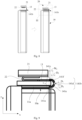
- Figs. 3 and 4 are schematic diagrams of structures of the sealant 14 in a bending state.
- the sealant 14 comprises an exposed portion 141 extending out of the top sealing 11a.
- the exposed portion 141 comprises a bending line O, and a first part 1411 and a second part 1412 arranged along an extension direction (i.e. the second direction y) of the tab 13.
- the bending line O is arranged between the first part 1411 and the second part 1412, that is, the bending line O divides the exposed portion 141 into the connected first part 1411 and second part 1412.
- the bending line O is on the sealant 14, and perpendicular to the extension direction y of the tab 13.
- the sealant 14 can be bent along the bending line O.
- the exposed portion 141 of the sealant 14 is bent along the bending line O.
- the circuit board 21 can be arranged adjacent to the top sealing 11a, correspondingly, the bent tab 13 extends to a side of the circuit board 21 facing away from the top sealing 11a (i.e. above as shown in Figs. 3 and 4 ).
- the circuit board 21 can be electrically connected with the tab 13 through a conductive member 22.
- the first part 1411 and the second part 1412 are arranged to connect along the second direction y.
- the bending line O can reduce a bending difficulty of the sealant 14, so that the length of the sealant 14 in the second direction y after bending can be reduced, which is conducive to reducing the packaging space required by the cell 10 and improving the capacity of the cell 10.
- the bending line O may be a design that does not destroy the structure of the sealant 14, for example, it is only a line marked or not marked on the sealant 14.
- a possible situation is that: a position where the sealant 14 is to be bent is not fixed, the exposed portion 141 of the sealant 14 is bent with the bending of the tab 13, and after bending, the exposed portion 141 is also arranged on a part of the tab 13 extending towards the circuit board 21.
- the tab 13 is bent towards the circuit board 21, and the exposed portion 141 of the sealant 14 is at least arranged at a tab bending area 133 of the tab 13 bent towards the circuit board 21.
- the exposed portion 141 is at least arranged at the tab bending area 133 and a second tab portion 132 of the tab 13.
- the bent tab 13 comprises a first tab portion (not shown), the second tab portion 132 and the tab bending area 133.
- the tab bending area 133 is connected to the first tab portion and the second tab portion 132.
- the first tab portion is electrically connected with the electrode assembly and extends towards the tab bending area 133.
- the second tab portion 132 extends towards the circuit board 21 and is electrically connected with the circuit board 21.
- the extension directions of the first tab portion and the second tab portion 132 are different, for example, as shown in Fig. 4 , the first tab portion extends along the third direction z, and the second tab portion 132 extends along an opposite direction of the third direction z, and the tab bending area 133 has an arc structure.
- the extension directions of the first tab portion and the second tab portion 132 may not be opposite, but have an angle that meets the design requirements, as long as the tab bending area 133 has an arc structure. It should be noted that the tab bending area 133 may not have two arc top angles as shown in Fig. 4 , but may also have an arc structure with other shapes, such as a structure with a single arc top angle.
- the bent sealant 14 is arranged not only in the bending area (i.e. the tab bending area 133) of the tab 13, but also in a part (i.e. the second tab portion 132) of the tab 13 extending towards the circuit board 21.
- the exposed portion 141 of the sealant 14 can not only protect the tab bending area 133 and the second tab portion 132 of the tab 13, but also reduce a length of the sealant 14 in the second direction y after bending, which is conducive to reducing the packaging space required by the cell 10 and improving the capacity of the cell 10.
- the sealant 14 can also be arranged in a part (i.e. the first tab portion)where the tab 13 is connected with the electrode assembly.
- the circuit board 21 may not exceed a thickness range of the main body 11b, which is conducive to reducing the overall thickness of the cell 10.
- an end of the circuit board 21 e.g., an end of the circuit board 21 facing away from the exposed portion 141 may be beyond the main body 11b.
- the electrical device e.g., battery compartment
- the end of the circuit board 21 beyond the main body part 11b may be combined with the space of the electrical device, so as to achieve assembly stability.
- an adhesive part (not shown) can be arranged between the top sealing 11a and the circuit board 21.
- the adhesive part is configured to insulate and fix the circuit board 21 on the top sealing 11a, for example, fix on a side face of the top sealing 11a facing away from the cell 10, which can reduce the risk of electrical contact between the circuit board 21 and the aluminum-plastic film (such as the aluminum-plastic film exposed at a fracture) of the top sealing 11a, and can reduce the length of the battery 10 in the second direction y.
- the adhesive part comprises at least one of double-sided adhesive, foam, hot-melt adhesive and silica gel, or other insulating and heat dissipation materials with viscosity.
- the adhesive part can completely or partially cover the top sealing 11a (and/or an overlapping area between the top sealing 11a and the circuit board 21), and/or the adhesive part can be arranged in a straight line or wave shape.
- the embodiment of the present application does not limit the shape of the adhesive part.
- each embodiment of the present application uses the same reference numerals to identify structural elements with the same name. Based on the description of the above embodiment, it is different therefrom that the bending line O of this embodiment is specifically implemented as an avoidance area 141d, that is, the bending line O is a design that destroys the structure of the sealant 14.
- the sealant 14 comprises the exposed portion 141 extending out of the top sealing 11a.
- the exposed portion 141 comprises a first part 1411 and a second portion 1412 which are arranged opposite to each other along the extension direction of the tab 13 (i.e. the second direction y).
- the avoidance area 141d is arranged between the first part 1411 and the second part 1412.
- the avoidance area 141d forms the bending line O perpendicular to the extension direction y of the tab 13 on the sealant 14. At the bending line O, the thickness of the sealant 14 is zero.
- the exposed portion 141 of the sealant 14 comprises a first sub part 141a, a bending area 141b and a second sub part 141c.
- the first sub part 141a is connected with the top sealing 11a and extends along the first direction x.
- the second sub part 141c is arranged opposite to the first sub part 141a along the second direction y, and the second sub part 141c is connected with the circuit board 21 and extends along the opposite direction of the first direction x.
- the bending area 141b is connected between the first sub part 141a and the second sub part 141c, and the bending area 141b is provided with an avoidance area 141d.
- the first part 1411 is deformed into the first sub part 141a, the first sub part 141a is arranged at the first tab portion, the second part 1412 is deformed into the bending area 141b and the second sub part 141c, the second sub part 141c is arranged at the second tab portion 132, and the bending area 141b is arranged at the tab bending area 133.
- the avoidance area 141d can reduce a bending difficulty of the sealant 14. After bending, the length of the tab 13 and the sealant 14 in the length direction (i.e. the second direction y) of the cell 10 can be reduced, which is conducive to reducing the packaging space required by the cell 10 and improving the capacity of the cell 10.
- the width of the top sealing 11a (i.e. the length of the top sealing 11a along the extension direction of the tab 13) is H 2 , and 1.0mm ⁇ H 2 ⁇ 4.0mm. Reducing H 2 is not only conducive to reducing the thickness of the cell 10, but also conducive to setting a longer exposed portion 141 in the thickness direction of the cell 10, so that it is conducive to the bending of the tab 13 and the sealant 14.
- the length of the bending area 141b in the second direction y can be understood as the length of an orthographic projection of the bending area 141b in the second direction y when viewed along the first direction x.
- the length of the sealant 14 in the non-bending state is greater than that in the bending state.
- the bending area 141b extends along the second direction y before bending, and both the first sub part 141a and the second sub part 141c extend along the second direction y and are arranged opposite to each other before bending.
- the first sub part 141a extends along the first direction x, and the second sub part 141c extends along the opposite direction of the first direction x.
- the length of the avoidance area 141d in the second direction y in the non-bending state is greater than that in the bending state.
- the bending area 141b comprises a first bending area 141e and a second bending area 141f which are arranged opposite to each other along the second direction y, and the avoidance area 141d is arranged between the first bending area 141e and the second bending area 141f.
- the avoidance area 141d is continuously distributed, on the exposed portion 141, perpendicular to the extension direction of the tab 13.
- the avoidance area 141d is continuously distributed on the bending area 141b along the third direction z, which can be regarded as the avoidance area 141d passing through the bending area 141b along the third direction z.
- a bending angle of the exposed portion 141 at the bending of the tab 13 is ⁇ 0 , and 60° ⁇ ⁇ 0 ⁇ 120°, which is conducive to the bending part of the tab 13 and the sealant 14.
- This bending angle ⁇ 0 can be understood as an included angle of the bending area 141b after bending.
- the bending area 141b comprising the arc-shaped first bending area 141e and the arc-shaped second bending area 141f which are arranged opposite to each other along the second direction y as an example, it is an included angle between a tangent of the first bending area 141e and a tangent of the second bending area 141f.
- both the first bending area 141e and the second bending area 141f are arc-shaped structures.
- the radius of curvature of the first bending area 141e is R 1
- the radius of curvature of the second bending area 141f is R 2 .
- the radius R 1 of curvature can be understood as a length equal to the distances to one end of the first bending area 141e, to the other end of the first bending area 141e, and to a middle point of one end and the other end on the first bending area 141e
- the radius R 2 of curvature can be understood as a length equal to the distances to one end of the second bending area 141f, to the other end of the second bending area 141f, and to a middle point of one end and the other end on the second bending area 141f.
- 0.1mm ⁇ R 2 ⁇ 0.5mm.
- the curvatures of the first bending area 141e and the second bending area 141f are reduced, and the length of the bending area 141b in the second direction y after bending is reduced, which is conducive to reducing the packaging space required by the cell 10 and improving the capacity of the cell 10.
- the height of the exposed portion 141 is H 0 , and 0.2mm ⁇ H 0 ⁇ 3.0mm.
- the avoidance area 141d can be made by a laser cutting process.
- the manufacturing method of the cell comprises the following steps S11 and S12.
- S11 placing a cell packing with sealant on a positioning device for positioning, wherein the sealant is located between a tab and a top sealing of the cell.
- the cell 10 with the non-bending tab 13 and sealant 14 is placed in a predetermined area and positioned by a positioning device 71, and a laser generation device 72 can generate a carbon dioxide laser.
- the laser pulse width is 10ns to 500ns, the frequency is 500 KHz to 2000 KHz, and the laser moving rate is 20mm/s to 50mm/s.
- the laser generation device 72 cuts one side of the sealant 14 (i.e. the sealant 14 located on one side face of the tab 13) along the third direction z, then turns the cell 10 and cuts the other side of the sealant 14 (i.e. the sealant 14 located on the other side face of the tab 13), so as to prepare the avoidance area 141d.
- the sealant 14 is cut with a continuous laser having a first energy to form a continuously distributed avoidance area 141d on the sealant 14.
- the continuously distributed avoidance area 141d is conducive to reducing the preparation difficulty.
- the length of the avoidance area 141d before bending may be greater than that after bending.
- the length of the avoidance area 141d after bending is D 1 , and 0 ⁇ D 1 ⁇ 0.4mm.
- the length of the first bending area 141e after bending is D 2 , and 0.2mm ⁇ D 2 ⁇ 1.0mm.
- D 2 the risk of puncturing the packaging tape by burrs or the like at the fracture (i.e. the cut edge) of the first bending area 141e can be reduced.
- the length of the first bending area 141e after bending can be understood as the length of an orthographic projection of the first bending area 141e in the second direction y when viewed along the first direction x.
- the length of the bending area 141b in the first direction x is D 3 , and 0.1mm ⁇ D 3 ⁇ 0.5mm.
- D 3 the length of the bending area 141b in the thickness direction of the cell 10 (i.e. the first direction x) is reduced, which is conducive to reducing the overall thickness of the cell 10.
- the length of the bending area 141b in the first direction x can be understood as the length of an orthographic projection of the bending area 141b (comprising the first bending area 141e and the second bending area 141f) in the first direction x when viewed along the second direction y.
- the top sealing 11a is bent towards the top surface 11b3, and an intersection of the top sealing 11a and the side sealing 11c forms a folding angle 11d.
- the preparation process of folding angle 11d is not limited by the embodiment of the present application, for example, comprising the following steps S21 to S23.
- the cell comprises a main body, a top sealing and a side sealing
- the main body comprises a bottom surface, a side surface and a top surface
- the side surface is connected with the bottom surface and the top surface
- the top sealing is connected to the top surface
- the side sealing is connected to the side surface
- the top sealing is connected to the side sealing
- an end of the side sealing away from the top surface has a first side
- an end of the top sealing away from the top surface has a second side.
- the cell 10 can be placed in the positioning fixture for positioning first, and then the side sealing can be bent through a first element, which pushes the side sealing to bend it towards the side surface 11b2, of the positioning fixture, and then the top sealing 11a can be bent through a second element, which pushes the top sealing 11a to bend it towards the top surface 11b3, of the positioning fixture, so as to obtain the folding angle 11d after bending.
- the first element may be a strip-shaped part extending along the second direction y
- the second element may be a strip-shaped part extending along the third direction z
- the first element and the second element may also be used to locate the cell 10.
- the top sealing 11a is pushed by a positioning block along the opposite direction of the second direction y to shape the folding angle 11d after bending, so as to finally obtain the folding angle 11d.
- An end of the side sealing 11c away from the top surface 11b3 has a first side 11c1
- an end of the top sealing 11a away from the top surface 11b3 has a second side 11a1.
- the first side 11c1 and the second side 11a1 can be regarded as two sides of the folding angle 11d.
- the included angle between the first side 11c1 and the second side 11a1 is ⁇ , and 5° ⁇ 60°.
- the included angle between the second side 11a1 and the top surface 11b3 is ⁇ ', and 60° ⁇ ' ⁇ 120°.
- the included angle ⁇ and included angle ⁇ ' are within the above threshold range, which can not only reduce the risk of damage of the top sealing 11a and the side sealing 11c due to stress at the bending part, but also reduce the length of the cell 10 in the second direction y, so as to meet the size requirements of external electrical device and have a wider application range.
- the folding angle 11d is almost perpendicular to the top surface 11b3, and the length in the width direction (e.g. the third direction z) can be reduced when matched with external electrical device (e.g. battery compartment).
- an opening length of the included angle (i.e., the folding angle 11d) between the first side 11c1 and the second side 11a1 is L 0 , and 1.0mm ⁇ L 0 ⁇ 8.0mm. Alternatively, 1.0mm ⁇ L 0 ⁇ 3.5mm.
- the opening length L 0 of the folding angle 11d can be understood as the distance between a point where the first side 11c1 intersects the top surface 11b3 and a point where the second side 11a1 intersects the top surface 11b3.
- the height of the first side 11c1 protruding from the top surface 11b3 is H 1 , and 1.0mm ⁇ H 1 ⁇ 4.0mm. Alternatively, 1.0mm ⁇ H 1 ⁇ 3.7mm, or 1.5mm ⁇ H 1 ⁇ 2.5mm. While reducing the risk of damage at the bending part of the top sealing 11a and the side sealing 11c, the length of the cell 10 in the second direction y is reduced as much as possible.
- the thickness of the aluminum-plastic film of the top sealing 11a and the side sealing 11c can preferably be 86 ⁇ m to 115 ⁇ m, which is conducive to the bending of top sealing 11a and side sealing 11c to form the folding angle 11d and avoid damage in the process of forming folding angle 11d. It goes without saying that it can also be 67 ⁇ m to 86 ⁇ m or 86 ⁇ m to 115 ⁇ m.
- the cell 10 may also comprise a thermistor (not shown).
- the thermistor is connected with the circuit board 21 through a wire, which can be arranged on the first end face 10a.
- the thermistor prevents the cell 10 from working when the temperature is too high.
- the thermistor can be set in the folding angle 11d so as to make full use of space of the folding angle 11d.
- the folding angle 11d may be filled with a filler, which is used to fix the shape of the folding angle 11d to reduce the deformation or even damage of the folding angle 11d.
- the filler can be glue, etc. the glue can be filled and cured within folding angle 11d. It goes without saying that the filler can also wrap the thermistor (or also wrap the wire connected thereto) to protect the thermistor.
- the shell 11 may comprise two side sealings 11c which are arranged opposite to each other along the third direction z. Accordingly, the shell 11 forms two folding angles 11d, the circuit board 21 may be arranged between the two folding angles 11d (or the side sealing 11c) and on the top surface 11b3, and both ends of the circuit board 21 are arranged opposite to the corresponding side sealings 11c. Both ends of the circuit board 21 are not in contact with the two folding angles 11d respectively, which can reduce the extrusion of both ends of the circuit board 21 to the side sealing 11c and reduce the risk of damage to the side sealing 11c due to collision.
- the distance between either end of the circuit board 21 and the corresponding side sealing 11c is W 1 , and 2.0mm ⁇ W 1 ⁇ 8.0mm.
- W 1 the distance between either end of the circuit board 21 and the corresponding side sealing 11c (i.e. the length along the third direction z) is W 1 , and 2.0mm ⁇ W 1 ⁇ 8.0mm.
- the exposed portion 141 is provided with a thinning area 141g, which forms a bending line O on the sealant 14.
- the thinning area 141g does not disconnect the sealant 14, but only thins the thickness of the sealant 14 in the thinning area 141g, and the thickness of the thinning area 141g is less than that of other positions.
- the position, shape, size, etc. of the thinning area 141g can be the same as those of the avoidance area 141d.
- the structural form of the exposed portion 141 after bending along the bending line O formed by the thinning area 141g and the resulting beneficial effects can be referred to above and will not be repeated herein.
- the sealant 14 is cut by a laser having a second energy to form the thinning area 141g on the sealant 14.
- the second energy is less than the first energy
- the first energy is the laser energy of cutting to form the avoidance area 141d.
- avoidance area 141d can also be arranged as the thinning area 141g, or both the avoidance area 141d and the thinning area 141g can be arranged at the same time.
- Figs. 17 and 18 are schematic diagrams of a structure of the sealant 14 in the non-bending state.
- avoidance areas 141d are distributed at intervals, on the exposed portion 141, perpendicular to the extension direction of the tab 13.
- the avoidance areas 141d are distributed at intervals along the third direction z on the bending area 141b.
- the first bending area 141e and the second bending area 141f are still connected but not completely disconnected, which is conducive to improving the structural strength of the bending area 141b, improving the protection effect of the tab 13, and reducing the risk of puncturing the packaging tape by burrs or the like at a fracture (i.e. the edges of the avoidance areas 141d) of the first bending area 141e and the second bending area 141f.
- the sealant 14 is cut with an intermittent laser having the first energy to form continuously distributed avoidance areas 141d on the sealant 14.
- an intermittent laser having the first energy is first used to form an avoidance area 141d, and then the energy of the laser is interrupted (i.e. no laser is generated), and at a position of the next avoidance area 141d, a continuous laser having the second energy is used to form an avoidance area 141d until a plurality of avoidance areas 141d distributed at intervals are formed.
- each avoidance area 141d can be a rectangle shown in Figs. 17 and 18 , a circle, or other types of polygons such as triangle.
- the embodiment of the present application is not limited.
- the number of avoidance areas 141d provided by the sealant 14 at each tab 13 is not limited in this embodiment, and the four avoidance areas 141d shown in Figs. 17 and 18 are only exemplary.
- Figs. 19 and 20 are schematic diagrams of a structure of the sealant 14 in the non-bending state.
- the length of the first bending area 141e before and after bending remains unchanged, and the length of the second bending area 141f before and after bending also remains unchanged.
- this embodiment identifies a difference between the lengths of the first bending area 141e and the second bending area 141f in Figs. 19 and 20 in which show the non-bending state.
- the length of the first part 1411 is less than that of the second part 1412 on at least one side of the tab 13 (such as the left and right sides shown in Fig. 19 ).
- the length of the second bending area 141f is less than that of the first bending area 141e on the first and second sides of the tab 13 (i.e., the left and right sides shown in Fig. 20 ), so as to reduce the risk of puncturing the packaging tape by burrs or the like at the fracture of the second bending area 141f.
- the difference between the lengths of the second bending area 141f and the first bending area 141e is D 0 , and 0.5mm ⁇ D 0 ⁇ 3.0mm. It should be understood that on the left or right side of the tab 13, the difference between the lengths of the second bending area 141f and the first bending area 141e may or may not be equal; or, the second bending area 141f and the first bending area 141e have a difference in length on only one side, and the length on the other side is equal (i.e., flush).
- the length of the first bending area 141e may be less than that of the second bending area 141f only on at least one side of the tab 13.
- Figs. 21 to 24 are schematic diagrams of a structure of the sealant 14 in the non-bending state
- Figs. 25 and 26 are schematic diagrams of a structure of the sealant 14 in the bending state.
- a first side portion is located on the left side of the tab 13 and a second side portion is located on the right side of the tab 13.
- the avoidance area 141d is arranged on the second side portion of the bending area 141b, that is, the bending area 141b is provided with an avoidance area 141d on the right side of the tab 13, and the avoidance area 141d can reduce the bending difficulty of the sealant 14.
- the sealant 14 is not provided with the avoidance area 141d on the inside of the tab 13, and the sealant 14 on the inside can reduce the risk of electrical contact between the tab 13 and the circuit board 21 and the aluminum-plastic film at a cut opening of the top sealing 11a, so as to reduce the safety risk caused by short circuit of the cell 10 as a whole.
- the length of the sealant 14 on a side of the tab 13 facing the top sealing 11a is D 4 , and 0.5mm ⁇ D 4 ⁇ 2.5mm.
- the circuit board 21 can be arranged adjacent to the top sealing 11a. Accordingly, the tab 13 after being bent extends to a side (i.e. above) of the circuit board 21 facing away from the top sealing 11a.
- the sealant 14 can comprise only the first sub part 141a and the bending area 141b.
- the bending area 141b can comprise two parts.
- One part connected with the first sub part 141a can be equivalent to the first bending area 141e described in the above embodiment, and the other part can extend along the second direction y without bending, which can reduce the bending part of the sealant 14 and reduce the risk of cracking of the sealant 14 due to bending.
- the above embodiments can also adopt the setting of this embodiment, that is, the bending area 141b is provided with an avoidance area 141d corresponding to each embodiment on the outside of the tab 13, while the inside is not provided with the avoidance area 141d, which can also reduce the safety risk caused by short circuit of the cell 10.
- the battery 20 comprises a circuit board 21 and the cell 10 according to any one of the above embodiments.
- the circuit board 21 is arranged on a side of the top sealing 11a facing away from the electrode assembly, and the circuit board 21 is electrically connected with the tab 13 of the cell 10.
- the circuit board 21 is electrically connected with the tab 13 through the conductive member 22.
- the circuit board 21 is fixed to an upper surface of the top sealing 11a to reduce the length of the head structure of the battery 20 in the second direction y, which is conducive to reducing the head space of the battery 20.
- the type of battery 20 applicable to the circuit board 21 is not limited by the embodiment of the present application, and the shape, size and function of the circuit board 21 can be determined according to the application scenes.
- the circuit board 21 may be a rigid circuit board, such as a printed circuit board (PCB), or a flexible printed circuit (FPC), and the circuit board 21 may be integrated with a BMS (Battery management system) for controlling the charge and discharge of the cell 10 and ensuring safety.
- PCB printed circuit board
- FPC flexible printed circuit
- the battery 20, which can be soft pack cells comprises but is not limited to all kinds of primary cells, secondary cells, fuel cells, solar cells and capacitor (e.g., super capacitor) cells.
- the battery 20 may preferably be a lithium secondary battery.
- the battery 20 of the embodiment of the present application may exist in the form of a single battery, a battery unit or a battery module.
- the embodiment of the present application further provides an electronic device, comprising a load and a battery 20 or cell 10 of any of the above embodiments, and the battery 20 or cell 10 supplies power to the load.
- Electronic device can be implemented in various specific forms, such as unmanned aerial vehicle, electric vehicle, electric cleaning tool, energy storage product, electric car, electric bicycle, electric navigation tool and other electronic product.
- electronic device specifically comprises but is not limited to: standby power supply, motor, automobile, motorcycle, power-assisted bicycle, bicycle electric tools, large household battery and lithium-ion capacitor.
- the battery 20 and the electronic device have the cell 10 of any of the above-mentioned embodiments, the battery 20 and the electronic device can produce the beneficial effects of the cell 10 of the corresponding embodiment.
- orientation or positional relationship indicated by the terms “center”, “longitudinal”, “transverse”, “length”, “width”, “thickness”, “upper”, “lower”, “front”, “rear”, “left”, “right”, “perpendicular”, “horizontal”, “top”, “bottom”, “inner”, “outer”, “clockwise”, “counterclockwise”, etc. is based on the orientation or positional relationship shown in the accompanying drawings, which is only for the convenience of describing the technical solution and simplified description of the corresponding embodiments of the present application, rather than indicating or implying that the devices or elements must have a specific orientation, and are constructed and operated in a specific orientation, so that it cannot be understood as a limitation of the present application.
Landscapes
- Chemical & Material Sciences (AREA)
- Chemical Kinetics & Catalysis (AREA)
- Electrochemistry (AREA)
- General Chemical & Material Sciences (AREA)
- Engineering & Computer Science (AREA)
- Manufacturing & Machinery (AREA)
- Sealing Battery Cases Or Jackets (AREA)
- Connection Of Batteries Or Terminals (AREA)
Abstract
Description
- The present application claims the priority of a Chinese patent application with the Application No.
202111028075.7 and the title of "CELL, BATTERY, MANUFACTURING METHOD OF CELL, AND ELECTRONIC DEVICE", which is filed to CNIPA on September 2, 2021 - The present application relates to the field of electrochemical technology, in particular to a cell, a battery, a manufacturing method of a cell, and an electronic device.
- With the vigorous development of electrochemical technology, people's requirements for the improvement of battery capacity are getting higher and higher. In order to improve battery capacity, manufacturers usually optimize a design of a head space of a battery, in which top sealing bending batteries are one of popular batteries currently. In the top sealing bending batteries, a top sealing of a battery is bent and fixed to one end face of the battery. Accordingly, a tab of the battery is also bent to facilitate electrical connection to the circuit board. However, a sealant is arranged between the tab and the top sealing, and in order to ensure a sealing effect of the top sealing at an extended position of the tab and avoid the tab contacting an exposed aluminum layer of the top sealing, the sealant will generally protrude a certain length from the top sealing. In addition, limited by the existing production process level, the length of the sealant protruding from the top sealing is often more than 1mm. Due to a high hardness of the sealant, it is not only difficult to be bent, but also occupies a large length in a length direction of the battery after bending, resulting in a waste of space in the length direction of the battery, which is not conducive to reducing a packaging space of the cell and improving the battery capacity.
- Embodiments of the present application provide a cell, a battery, a manufacturing method of a cell, and an electronic device, which reduces a bending difficulty of sealant, and reduces a length of the sealant after bending occupied in the length direction of the battery.
- In a first aspect, an embodiment of the present application provides a cell, comprising: a shell, an electrode assembly, a tab, and a sealant; the shell comprises a main body and a top sealing, the main body comprises a bottom surface, a side surface and a top surface, the side surface is connected with the bottom surface and the top surface, and the top sealing is connected to the top surface and is bent towards the top surface; the electrode assembly is housed in the main body; one end of the tab is electrically connected to the electrode assembly, and the other end of the tab extends out of the top sealing; the sealant is located between the tab and the top sealing; the sealant comprises an exposed portion extending out of the top sealing, the exposed portion is provided with a bending line, the bending line is on the sealant, and perpendicular to an extension direction of the tab. Optionally, along the extension direction of the tab, the bending line is arranged opposite to the top sealing. The bending line can reduce the bending difficulty of the sealant, so that the length of the exposed portion after bending in the length direction of the cell can be reduced, which is conducive to improving the capacity of the cell.
- In some embodiments, a stress required for bending the sealant at the bending line is smaller than that required for bending the sealant at other positions, which facilitates the bending of the sealant.
- In some embodiments, the exposed portion is provided with an avoidance area and/or a thinning area, and the avoidance area and/or the thinning area is provided for bending of the tab. Optionally, the avoidance area and/or the thinning area forms the bending line on the sealant.
- In some embodiments, the exposed portion comprises a first part and a second part which are arranged oppositely along an extension direction of the tab, and the bending line is arranged between the first part and the second part. The second part can increase an area of the tab covered by the sealant, and reduces an exposed part of the tab, which is conducive to the protection of the tab.
- In some embodiments, the avoidance area and/or the thinning area is continuously distributed, on the exposed portion, perpendicular to the extension direction of the tab. The avoidance area and/or the thinning area is continuously distributed between the first bending area and the second bending area, which can be regarded as the avoidance area and/or the thinning area passing through the bending area along a third direction (e.g., the third direction is perpendicular to the extension direction of the tab), and it is conducive to reducing preparation difficulty of the avoidance area and/or the thinning area.
- In some embodiments, the avoidance areas and/or the thinning areas are distributed at intervals, on the exposed portion, perpendicular to the extension direction of the tab. The first part and the second part are still connected and are not disconnected, which is conducive to the structural strength of the exposed portion and the protection of the tab. In addition, after bending, the risk of electrical contact between the tab and the aluminum-plastic film at a cut opening on of the top sealing can be reduced, so as to reduce the safety risk caused by short circuit.
- In some embodiments, the exposed portion comprises a first part and a second part which are arranged oppositely along an extension direction of the tab; along a direction perpendicular to extension direction of the tab, an length of the first part is less than that of the second part on at least one side of the tab, which can reduce the risk of puncturing the packaging tape by burrs or the like at the fracture (i.e. the edge of the bending line) of the exposed portion after bending. Optionally, along a direction perpendicular to the extension direction of the tab, on at least one side of the tab, a difference between the lengths of the second part and the first part is D0, and 0.5mm<D0≤3.0mm.
- In some embodiments, a distance between the avoidance area and/or the thinning area and the top sealing is W0, and 0.2mm<W0≤1.0mm. Optionally, W0=0.5mm, which facilitates bending of the sealant.
- In some embodiments, along the extension direction of the tab, a height of the exposed portion is H0, and 0.2mm<H0≤3.0mm.
- In some embodiments, along the extension direction of the tab, the length of the top sealing is H2, and 1.0mm<H2≤4.0mm.
- In some embodiments, the bending line is arranged on a side of the exposed portion located at the tab. That is, on one side of the tab, the sealant is provided with a bending line, while on the other side of the tab, the sealant is not provided with bending line, which can reduce a bending difficulty of the sealant. In addition, when the bending line is provided on a side of the bending area facing away from the top sealing, after bending, the sealant facing the top sealing can reduce the risk of electrical contact between the tab and the aluminum-plastic film at a cut opening of the top sealing, so as to reduce the safety risk caused by short circuit.
- In a second aspect, an embodiment of the present application provides a manufacturing method of a cell, used to manufacture any one of the above-mentioned cells, wherein the method comprises: placing the cell packing with a sealant on a positioning device for positioning, wherein the sealant is located between the tab and the top sealing of the cell; and using a laser to cut the sealant along a width direction of the tab to form a bending line on the sealant, wherein the bending line comprises an avoidance area and/or a thinning area, and the avoidance area and/or the thinning area is provided for bending of the tab.
- In some embodiments, the sealant is cut with a continuous laser having a first energy to form avoidance areas being continuously distributed on the sealant.
- In some embodiments, the sealant is cut with an intermittent laser having a first energy to form avoidance areas being distributed at intervals on the sealant.
- In some embodiments, the sealant is cut with a laser having a second energy to form thinning areas on the sealant, and the second energy is less than the first energy.
- In some embodiments, the laser is a carbon dioxide laser, a pulse width of the laser is 10ns to 500ns, a frequency is 500 KHz to 2000 KHz, and a moving rate of the laser is 20mm/s to 50mm/s.
- In a third aspect, an embodiment of the present application provides a battery, comprising: a shell, an electrode assembly, a tab, a sealant, and a circuit board. The shell comprises a main body and a top sealing, the main body comprises a bottom surface, a side surface and a top surface, the side surface is connected with the bottom surface and the top surface, and the top sealing is connected to the top surface and is bent towards the top surface; the electrode assembly is housed in the main body; one end of the tab is electrically connected to the electrode assembly, and the other end of the tab extends out of the top sealing; the circuit board is arranged on a side of the top sealing facing away from the electrode assembly and electrically connected with the tab of the cell; the sealant is located between the tab and the top sealing and comprises an exposed portion extending out of the top sealing, the exposed portion is provided with a bending area, and the tab is arranged to bend in the bending area. The exposed portion of the sealant can be bent with the bending of the tab, and the length of the sealant after bending in the length direction of the cell can be reduced, which is conducive to improving the capacity of the cell.
- In some embodiments, the exposed portion comprises a first sub part and a second sub part, the first sub part is connected with the top sealing and extends along a first direction, the second sub part is connected with the circuit board and extends along an opposite direction of the first direction, and the bending area connects the first sub part and the second sub part.
- In some embodiments, a stress required for bending the sealant at the bending area is smaller than that required for bending the sealant at other positions.
- In some embodiments, the bending area is provided with an avoidance areas and/or a thinning area.
- In some embodiments, the bending area comprises a first bending area and a second bending area which are arranged oppositely along a second direction, and the bending line is arranged between the first bending area and the second bending area.
- In some embodiments, avoidance areas and/or thinning areas are distributed continuously on the bending area along a third direction, and the third direction is perpendicular to the first direction and the second direction. The avoidance areas and/or the thinning areas are distributed continuously between the first bending area and the second bending area, which can be regarded as the avoidance areas and/or the thinning areas passing through the bending area along a third direction, which is conducive to reducing preparation difficulty of the avoidance area and/or the thinning area.
- In some embodiments, the avoidance areas and/or the thinning areas are distributed at intervals on the bending area along a third direction, and the third direction is perpendicular to the first direction and the second direction. The first bending area and the second bending area are still connected and are not disconnected, which is conducive to improve the structural strength of the bending area, protect the tab, and reduce the risk of puncturing the packaging tape by burrs or the like at the fracture (i.e. the edge of the bending line) of the first bending area and the second bending area. The packaging tape is used to package and protect the head structure of the cell so as to, for example, electrically insulate the head structure from the outside, or the like.
- In some embodiments, the bending area comprises a first bending area and a second bending area which are arranged oppositely along a second direction. Along a third direction, an length of the first bending area is less than that of the second bending area on at least one side of the tab. The third direction is perpendicular to the first direction and the second direction. The risk of puncturing the packaging tape by burrs or the like at the fracture (i.e. the edge of the bending line) of the first bending area can be reduced. Optionally, along the third direction, on either side of the tab, a difference between the lengths of the second bending area and the first bending area is D0, and 0.5mm<D0≤3.0mm.
- In some embodiments, a bending angle of the bending area is α0, and 60°≤α0 ≤120°.
- In some embodiments, a radius of curvature of the first bending area is R1, a radius of curvature of the second bending area is R2, and 0.1mm≤R1≤0.5mm, 0.1mm≤R2≤0.5mm.
- In some embodiments, an adhesive part is arranged between the top sealing and the circuit board, the adhesive part is configured to insulate and fix the circuit board on the top sealing, which can reduce the risk of electrical contact between the circuit board and the aluminum-plastic film (e.g., the aluminum-plastic film exposed at the fracture) of the top sealing, and reduce the length in the length direction of the battery. Optionally, the adhesive part comprises at least one of double-sided adhesive, foam, hot-melt adhesive and silica gel.
- In a fourth aspect, an embodiment of the present application provides a cell, comprising: a shell, an electrode assembly, a tab, and a sealant. The shell comprises a main body and a top sealing, the main body comprises a bottom surface, a side surface and a top surface, the side surface is connected with the bottom surface and the top surface, and the top sealing is connected to the top surface and is bent towards the top surface. The electrode assembly is housed in the main body. One end of the tab is electrically connected to the electrode assembly, and the other end of the tab extends out of the top sealing. The sealant is located between the tab and the top sealing. the shell further comprises a side sealing, the side sealing is connected to the side surface and bent towards the side surface, the top sealing is connected with the side sealing, an end of the side sealing away from the top surface has a first side, an end of the top sealing away from the top surface has a second side, an included angle between the first side and the second side is α, and 5°≤α≤60°, and an included angle between the second side and the top surface is α', and 60°≤α'≤120°. By bending the top sealing and controlling thresholds of the included angles α and α', not only can the risk of damage of the top sealing and the side sealing at the bending part be reduced, but also the length of the cell can be reduced, thereby meeting the size requirements of external electrical device and expanding an application range.
- In some embodiments, an opening length of the included angle between the first side and the second side is L0, and 1.0mm≤L0≤8.0mm. Optionally, 1.0mm≤L0 ≤3.5mm. While reducing the length of the cell in the second direction, the risk of damage of the top sealing and the side sealing at the bending part is reduced.
- In some embodiments, a height of the first side protruding from the top surface is H1, and 1.0mm<H1≤4.0mm. Optionally, 1.0mm<H1≤3.7mm, or, 1.5mm <H1≤2.5mm. While reducing the risk of damage of the top sealing and the side sealing at the bending part, the length of the cell is reduced.
- In some embodiments, a thickness of the aluminum-plastic film of the top sealing and the side sealing is 67µm to 150µm, preferably, 86µm to 115µm, which is conductive to the bending of the top sealing and the side sealing.
- In some embodiments, the cell further comprises a thermistor, and the thermistor can be arranged in the included angle of the first side and the second side. The thermistor is configured to prevent the cell from working at a too high temperature.
- In some embodiments, the included angle of the first side and the second side is filled with a filler, and the filler is used to fix the folding angle of the first side and the second side. Optionally, the filler is glue.
- A fifth aspect, an embodiment of the present application provides a battery, comprising a circuit board and any one of the above-mentioned cells, wherein the circuit board and the tab of the cell are electrically connected.
- In some embodiments, the shell comprises two side sealings which are arranged oppositely, the circuit board is arranged between the two side sealings, and on the top sealing, and both ends of the circuit board are arranged opposite to the corresponding side sealings. It can not only reduce the extrusion of both ends of the circuit board to the side sealing, but also reduce the risk of damage to the side sealing due to collision.
- In some embodiments, a distance between either end of the circuit board and the corresponding side sealing is W1, and 2.0mm<W1≤8.0mm.
- In some embodiments, an adhesive part is arranged between the top sealing and the circuit board, the adhesive part is configured to insulate and fix the circuit board on the top sealing, which can reduce the risk of electrical contact between the circuit board and the aluminum-plastic film (e.g., the aluminum-plastic film exposed at the fracture) of the top sealing, and reduce the length in the length direction of the battery. Optionally, the adhesive part comprises at least one of double-sided adhesive, foam, hot-melt adhesive and silica gel.
- A sixth aspect, an embodiment of the present application provides a manufacturing method of a cell, used to manufacture any one of the above-mentioned cells, wherein the method comprises: placing the cell in a positioning fixture for positioning, wherein the cell comprises a main body, a top sealing and a side sealing, the main body comprises a bottom surface, a side surface and a top surface, the side surface is connected with the bottom surface and the top surface, the top sealing is connected to the top surface, the side sealing is connected to the side surface, the top sealing is connected to the side sealing, an end of the side sealing away from the top surface has a first side, and an end of the top sealing away from the top surface has a second side; bending the side sealing towards the side surface; and bending the top sealing towards the top surface, and an included angle between the first side and the second side is α, and 5°≤α≤60°, an included angle between the second side and the top surface is α', and 60°≤α'≤120°.
- A seventh aspect, an embodiment of the present application provides an electronic device, comprising a load and any one of the above-mentioned cells or batteries, wherein the cell or battery is configured to supply power to the load.
- As mentioned above, according to the cell, the battery, the manufacturing method of the cell, and the electronic device provided by embodiments of the present application, the exposed portion of the sealant is provided with a bending line, and the exposed portion can be bent along the bending line, and the length in the length direction of the cell after being bent can be reduced, which is conducive to reducing the packaging space of the cell and improving the capacity of the cell.
-
-
Fig. 1 is a three-dimensional schematic diagram of a structure of a cell provided by an embodiment of the present application. -
Fig. 2 is a front view of a cell according to First Embodiment of the present application. -
Fig. 3 is a schematic diagram of electrically connection of the cell shown inFig. 2 with a circuit board and bending sealant. -
Fig. 4 is an enlarged view of a structure of Area I of a battery shown inFig. 3 . -
Fig. 5 is a front view of a cell according to Second Embodiment of the present application. -
Fig. 6 is an enlarged view of a structure of Area II of the cell shown inFig. 5 . -
Fig. 7 is a schematic diagram of a structure of a cell of the present application when the sealant is not cut by laser. -
Fig. 8 is a schematic diagram of electrically connection of the cell shown inFig. 5 with a circuit board and bending sealant. -
Fig. 9 is an enlarged view of a structure of Area III of the battery shown inFig. 8 . -
Fig. 10 is a diagram of a structure of the battery shown inFig. 8 when viewed along a first direction. -
Fig. 11 is a schematic diagram of a scene where the sealant is cut by laser according to an embodiment of the present application. -
Fig. 12 is a flowchart of a manufacturing method of a cell according to an embodiment of the present application. -
Fig. 13 is an enlarged view of a structure of Area A of the cell shown inFig. 1 . -
Fig. 14 is an enlarged view of a structure of Area B of the cell shown inFig. 1 . -
Fig. 15 is a flowchart of a manufacturing method of a cell according to another embodiment of the present application. -
Fig. 16 is an enlarged view of a structure of Area III of the battery shown inFig. 8 . -
Fig. 17 is a schematic diagram of a structure of a cell according to Fourth Embodiment of the present application. -
Fig. 18 is an enlarged view of a structure of Area IV of the battery shown inFig. 17 . -
Fig. 19 is a diagram of a structure of a cell according to Fifth Embodiment of the present application. -
Fig. 20 is an enlarged view of a structure of Area V of the battery shown inFig. 19 . -
Fig. 21 is a schematic diagram of a structure of a cell according to Sixth Embodiment of the present application when viewed along an opposite direction of the first direction. -
Fig. 22 is an enlarged view of a structure of Area VI of the cell shown inFig. 21 . -
Fig. 23 is a schematic diagram of a structure of a cell according to Sixth Embodiment of the present application when viewed along the first direction. -
Fig. 24 is an enlarged view of a structure of Area VII of the battery shown inFig. 23 . -
Fig. 25 is a schematic diagram of electrically connection of the cell shown inFig. 22 with a circuit board and bending sealant. -
Fig. 26 is an enlarged view of a structure of Area VIII of the battery shown inFig. 23 . - In a cell and a battery provided by an embodiment of the present application, in a state when a tab is bent towards a circuit board, an exposed portion of sealant is provided with a bending area, and the tab is arranged to bend in the bending area, that is, the exposed portion of the sealant can be bent with the bending of the tab. After bending, the exposed portion of the sealant can not only protect the bending area of the tab and a part of the tab extending towards the circuit board, but also reduce the length of the cell, which is conducive to reducing the packaging space required by the cell and improving the capacity of the cell.
- In order to make the purpose, technical solution and advantages of the present application clearer, the technical solution of the present application will be clearly described hereinafter in combination with specific embodiments and corresponding drawings. It goes without saying that the embodiments described hereinafter are only a part of the embodiments of the present application, not all of the embodiments. Without conflict, the following embodiments and their technical features can be combined with each other, and also belong to the technical solution of the present application.
- Referring to
Figs. 1 to 4 together, acell 10 of this embodiment comprises ashell 11, an electrode assembly (not shown), atab 13, and asealant 14. - The
shell 11 is surrounded to form a shape of thecell 10 and can also be configured to define an appearance of thecell 10. For example, theshell 11 comprises atop sealing 11a, amain body 11b and a side sealing 11c. The electrode assembly is arranged in themain body 11b. Thetop sealing 11a and thetab 13 extend from a first end face of themain body 11b. The first end face of themain body 11b can be regarded as afirst end face 10a of thecell 10, which will be described hereinafter as an example. Themain body 11b is formed with a housing cavity, internal components of the cell 10 (such as electrode assembly and electrolyte) are built in the housing cavity, and theshell 11 is configured to protect the internal components, so as to improve the protection effect and safety. - The
main body 11b comprises a bottom surface 11b1, a side surface 11b2 and a top surface 11b3. The bottom surface 11b1 and the top surface 11b3 are arranged opposite to each other. The side surface 11b2 is connected with the bottom surface 11b1 and the top surface 11b3. Thetop sealing 11a and the side sealing 11c are formed by packaging theshell 11 after the electrode assembly is housed in themain body 11b. Thetop sealing 11a is connected with the top surface 11b3, and the side sealing 11c is connected with the side surface 11b2. - On the
first end face 10a of the top surface 11b3 of themain body 11b, thetop sealing 11a is configured to realize sealing of theshell 11, so as to avoid the leakage of electrolyte from thefirst end face 10a, and the entry of impurities such as water and oxygen outside theshell 11 into theshell 11 from thefirst end face 10a. Thetop sealing 11a also seals an extending area of thetab 13 for sealing a joint between theshell 11 and thetab 13. - The
side sealing 11c is bent towards the side surface 11b2, and thetop sealing 11a is bent towards the top surface 11b3. By bending the side sealing 11c and thetop sealing 11a, the width and length of thecell 10 are reduced, so as to meet size requirements of external electrical device and expand an application range. In addition, since the side sealing 11c and thetop sealing 11a are relatively weak components in thecell 10, by bending the side sealing 11c and the top sealing 11a towards themain body 11b of theshell 11, the side sealing 11c and thetop sealing 11a are not easy to be damaged due to collision and other reasons, so that a service life of theelectric core 10 provided in the embodiment of the present application is long. - The
top sealing 11a is a structure protruding from themain portion 11b of thecell 10. As shown inFig. 1 , thetop sealing 11a does not extend along a second direction y, but bends towards thefirst end face 10a and is fixed to thefirst end face 10a, so as to reduce an overall length of thecell 10. The second direction y is the length direction of thecell 10. It should be understood that in thecell 10, referring toFig. 2 , thetop sealing 11a can also extend along the second direction y without being bent, and at this time, the tab is not bent, either, and an extension direction of thetab 13 is the second direction y. In the embodiment of the present application, a thickness direction of thecell 10 can be a first direction x, a width direction of thetab 13 can be a third direction z, and two of the first direction x, the second direction y and the third direction z are perpendicular. It should be noted that due to the error in actual processing or measurement, the so-called perpendicularity in the description of the present application does not require that an included angle between the two must be 90°, instead, a deviation of ±10° is allowed, that is, the so-called perpendicularity can be understood as the included angle between any two directions is 80° to 100°. - The
top sealing 11a is bent towards thefirst end face 10a and fixed to thefirst end face 10a, comprising any of the following three scenes: in a first scene, thetop sealing 11a is in contact with at least a part of thefirst end face 10a, for example, a part of a side face of thetop sealing 11a close to thefirst end face 10a is in contact with thefirst end face 10a, or, the entire side face of thetop sealing 11a close to thefirst end face 10a is in contact with thefirst end face 10a; in a second scene, along the second direction y, thetop sealing 11a and thefirst end face 10a are arranged opposite to each other, and there is no contact between the two and there is a predetermined distance., and the predetermined distance can be determined according to the actual scene requirements, for example, it can be greater than 0 and less than or equal to 1mm; in a third scene, an adhesive part, such as double-sided adhesive, foam, hot-melt adhesive, silica gel, viscous heat dissipation materials with viscosity, etc., preferably hot-melt adhesive, is arranged between thetop sealing 11a and thefirst end face 10a of the top surface 11b3. The adhesive part can completely or partially cover thefirst end face 10a, and/or, the adhesive part can be arranged on thefirst end face 10a in a straight line or wave shape (the embodiments of the present application do not limit the shape of the adhesive part), and thetop sealing 11a is bonded to thefirst end face 10a of the top surface 11b3. - In a scene where the
cell 10 has positive and negative polarities, the electrode assembly comprises a positive electrode and a negative electrode, and a separator arranged between the positive electrode and the negative electrode. The electrode assembly may be formed by winding or laminating a plurality of electrodes, one end of thetab 13 is electrically connected to the electrode assembly, for example, extends into theshell 11 and is electrically connected with the electrode of the corresponding polarity, and the other end of thetab 13 extends out of thetop sealing 11a. - The
tab 13 comprises afirst tab 13a and asecond tab 13b. Thefirst tab 13a is a negative tab, and correspondingly, thesecond tab portion 13b is a positive tab. Thefirst tab 13a is electrically connected with the negative electrode, and thesecond tab 13b is electrically connected with the positive electrode, and extends to the outside of theshell 11 respectively. In other embodiments, thefirst tab 13a may be a positive tab and thesecond tab 13b may be a negative tab. The structures of thefirst tab 13a and thesecond tab 13b can be the same or different, and both can be arranged symmetrically or asymmetrically along the third direction z. In some parts of this description, the structure of thetab 13 of the embodiment of the present application is described by taking one of them as an example. - It should be understood that the structure and shape of the
tab 13 are not limited by the embodiments of the present application. For example, thetabs 13 can have a rectangular strip structure, and their respective sizes can be set adaptively according to actual needs. The materials comprise but are not limited to aluminum, nickel, copper, nickel-plated copper and other alloys. For example, the material of thepositive tab 13 can be aluminum or nickel-plated aluminum, and the material of thenegative tab 13 can be nickel-plated copper, which is not only conducive to improving the electrical connection performance with the negative electrode, but also improving the structural strength of the negative tab. - The
sealant 14 is located between thetab 13 and thetop sealing 11a. Thesealant 14 is bonded with thetab 13 and also bonded with the shell 11 (such as an aluminum-plastic film of a soft shell), so as to improve a sealing effect of theshell 11 at thetab 13. Thesealant 14 can be arranged on a first surface and a second surface of thetab 13 respectively, and the first surface and the second surface are arranged oppositely along the thickness direction of thetab 13. -
Figs. 1 and2 are schematic diagrams of structures of thesealant 14 in a non-bending state.Figs. 3 and 4 are schematic diagrams of structures of thesealant 14 in a bending state. - Referring to
Figs. 1 and2 , as for thesealant 14 in the non-bending state, thesealant 14 comprises an exposedportion 141 extending out of thetop sealing 11a. The exposedportion 141 comprises a bending line O, and afirst part 1411 and asecond part 1412 arranged along an extension direction (i.e. the second direction y) of thetab 13. The bending line O is arranged between thefirst part 1411 and thesecond part 1412, that is, the bending line O divides the exposedportion 141 into the connectedfirst part 1411 andsecond part 1412. The bending line O is on thesealant 14, and perpendicular to the extension direction y of thetab 13. Thesealant 14 can be bent along the bending line O. - Referring to
Figs. 3 and 4 together, in a scene of connecting thecell 10 of this embodiment and thecircuit board 21 to form thebattery 20, the exposedportion 141 of thesealant 14 is bent along the bending line O. When thesealant 14 is in a bending state, thecircuit board 21 can be arranged adjacent to thetop sealing 11a, correspondingly, thebent tab 13 extends to a side of thecircuit board 21 facing away from thetop sealing 11a (i.e. above as shown inFigs. 3 and 4 ). Thecircuit board 21 can be electrically connected with thetab 13 through aconductive member 22. In this scene, thefirst part 1411 and thesecond part 1412 are arranged to connect along the second direction y. The bending line O can reduce a bending difficulty of thesealant 14, so that the length of thesealant 14 in the second direction y after bending can be reduced, which is conducive to reducing the packaging space required by thecell 10 and improving the capacity of thecell 10. - In this embodiment, the bending line O may be a design that does not destroy the structure of the
sealant 14, for example, it is only a line marked or not marked on thesealant 14. - For a scene where the bending line O is a line not marked on the
sealant 14, continuing to refer toFigs. 3 and 4 , a possible situation is that: a position where thesealant 14 is to be bent is not fixed, the exposedportion 141 of thesealant 14 is bent with the bending of thetab 13, and after bending, the exposedportion 141 is also arranged on a part of thetab 13 extending towards thecircuit board 21. In some embodiments, thetab 13 is bent towards thecircuit board 21, and the exposedportion 141 of thesealant 14 is at least arranged at a tab bending area 133 of thetab 13 bent towards thecircuit board 21. The exposedportion 141 is at least arranged at the tab bending area 133 and asecond tab portion 132 of thetab 13. Thebent tab 13 comprises a first tab portion (not shown), thesecond tab portion 132 and the tab bending area 133. The tab bending area 133 is connected to the first tab portion and thesecond tab portion 132. The first tab portion is electrically connected with the electrode assembly and extends towards the tab bending area 133. Thesecond tab portion 132 extends towards thecircuit board 21 and is electrically connected with thecircuit board 21. The extension directions of the first tab portion and thesecond tab portion 132 are different, for example, as shown inFig. 4 , the first tab portion extends along the third direction z, and thesecond tab portion 132 extends along an opposite direction of the third direction z, and the tab bending area 133 has an arc structure. It goes without saying that, in other embodiments, the extension directions of the first tab portion and thesecond tab portion 132 may not be opposite, but have an angle that meets the design requirements, as long as the tab bending area 133 has an arc structure. It should be noted that the tab bending area 133 may not have two arc top angles as shown inFig. 4 , but may also have an arc structure with other shapes, such as a structure with a single arc top angle. - In the embodiment of the present application, the
bent sealant 14 is arranged not only in the bending area (i.e. the tab bending area 133) of thetab 13, but also in a part (i.e. the second tab portion 132) of thetab 13 extending towards thecircuit board 21. The exposedportion 141 of thesealant 14 can not only protect the tab bending area 133 and thesecond tab portion 132 of thetab 13, but also reduce a length of thesealant 14 in the second direction y after bending, which is conducive to reducing the packaging space required by thecell 10 and improving the capacity of thecell 10. It goes without saying that thesealant 14 can also be arranged in a part (i.e. the first tab portion)where thetab 13 is connected with the electrode assembly. - In the first direction x, as shown in
Figs. 3 and 4 , thecircuit board 21 may not exceed a thickness range of themain body 11b, which is conducive to reducing the overall thickness of thecell 10. In other embodiments, an end of the circuit board 21 (e.g., an end of thecircuit board 21 facing away from the exposed portion 141) may be beyond themain body 11b. When thecell 10 is matched with the electrical device (e.g., battery compartment), the end of thecircuit board 21 beyond themain body part 11b may be combined with the space of the electrical device, so as to achieve assembly stability. - In some embodiments, an adhesive part (not shown) can be arranged between the
top sealing 11a and thecircuit board 21. The adhesive part is configured to insulate and fix thecircuit board 21 on thetop sealing 11a, for example, fix on a side face of thetop sealing 11a facing away from thecell 10, which can reduce the risk of electrical contact between thecircuit board 21 and the aluminum-plastic film (such as the aluminum-plastic film exposed at a fracture) of thetop sealing 11a, and can reduce the length of thebattery 10 in the second direction y. Alternatively, the adhesive part comprises at least one of double-sided adhesive, foam, hot-melt adhesive and silica gel, or other insulating and heat dissipation materials with viscosity. The adhesive part can completely or partially cover thetop sealing 11a (and/or an overlapping area between thetop sealing 11a and the circuit board 21), and/or the adhesive part can be arranged in a straight line or wave shape. The embodiment of the present application does not limit the shape of the adhesive part. - Each embodiment of the present application uses the same reference numerals to identify structural elements with the same name. Based on the description of the above embodiment, it is different therefrom that the bending line O of this embodiment is specifically implemented as an
avoidance area 141d, that is, the bending line O is a design that destroys the structure of thesealant 14. - As shown in
Figs. 5 to 7 , as for thenon-bending sealant 14, thesealant 14 comprises the exposedportion 141 extending out of thetop sealing 11a. The exposedportion 141 comprises afirst part 1411 and asecond portion 1412 which are arranged opposite to each other along the extension direction of the tab 13 (i.e. the second direction y). Theavoidance area 141d is arranged between thefirst part 1411 and thesecond part 1412. Theavoidance area 141d forms the bending line O perpendicular to the extension direction y of thetab 13 on thesealant 14. At the bending line O, the thickness of thesealant 14 is zero. - As shown in
Figs. 8 and 9 , as for thesealant 14 in the bending state, the exposedportion 141 of thesealant 14 comprises afirst sub part 141a, abending area 141b and asecond sub part 141c. Thefirst sub part 141a is connected with thetop sealing 11a and extends along the first direction x. Thesecond sub part 141c is arranged opposite to thefirst sub part 141a along the second direction y, and thesecond sub part 141c is connected with thecircuit board 21 and extends along the opposite direction of the first direction x. The bendingarea 141b is connected between thefirst sub part 141a and thesecond sub part 141c, and thebending area 141b is provided with anavoidance area 141d. Thereinto, after thecell 10 changes from a state ofFigs. 5 and6 to a state ofFigs. 8 and 9 , thefirst part 1411 is deformed into thefirst sub part 141a, thefirst sub part 141a is arranged at the first tab portion, thesecond part 1412 is deformed into thebending area 141b and thesecond sub part 141c, thesecond sub part 141c is arranged at thesecond tab portion 132, and thebending area 141b is arranged at the tab bending area 133. - The
avoidance area 141d can reduce a bending difficulty of thesealant 14. After bending, the length of thetab 13 and thesealant 14 in the length direction (i.e. the second direction y) of thecell 10 can be reduced, which is conducive to reducing the packaging space required by thecell 10 and improving the capacity of thecell 10. - In some embodiments, after the
sealant 14 is bent, as shown inFig. 9 , the distance between theavoidance area 141d and thetop sealing 11a is W0, and 0.2mm<W0≤1.0mm. Reducing W0 is conducive to the bending of the tab13 and thesealant 14. Alternatively, if W0=0.5mm, it is not only conducive to the bending of thetab 13 and thesealant 14, but also reduces the thickness of the cell 10 (i.e. the length in the first direction x). - In addition, referring to
Figs. 1 and13 , the width of thetop sealing 11a (i.e. the length of thetop sealing 11a along the extension direction of the tab 13) is H2, and 1.0mm<H2≤4.0mm. Reducing H2 is not only conducive to reducing the thickness of thecell 10, but also conducive to setting a longer exposedportion 141 in the thickness direction of thecell 10, so that it is conducive to the bending of thetab 13 and thesealant 14. - The length of the
bending area 141b in the second direction y can be understood as the length of an orthographic projection of thebending area 141b in the second direction y when viewed along the first direction x. Along the second direction y, the length of thesealant 14 in the non-bending state is greater than that in the bending state. Accordingly, as shown inFigs. 5 to 7 , the bendingarea 141b extends along the second direction y before bending, and both thefirst sub part 141a and thesecond sub part 141c extend along the second direction y and are arranged opposite to each other before bending. After bending, thefirst sub part 141a extends along the first direction x, and thesecond sub part 141c extends along the opposite direction of the first direction x. The length of theavoidance area 141d in the second direction y in the non-bending state is greater than that in the bending state. - Referring to
Figs. 8 and 9 together, the bendingarea 141b comprises afirst bending area 141e and asecond bending area 141f which are arranged opposite to each other along the second direction y, and theavoidance area 141d is arranged between thefirst bending area 141e and thesecond bending area 141f. In this embodiment, when thecell 10 is in the non-bending state, theavoidance area 141d is continuously distributed, on the exposedportion 141, perpendicular to the extension direction of thetab 13. When thecell 10 is in the bending state, theavoidance area 141d is continuously distributed on thebending area 141b along the third direction z, which can be regarded as theavoidance area 141d passing through the bendingarea 141b along the third direction z. - In some embodiments, after the
sealant 14 is bent, as shown inFig. 9 , a bending angle of the exposedportion 141 at the bending of thetab 13 is α0, and 60°≤ α0≤120°, which is conducive to the bending part of thetab 13 and thesealant 14. This bending angle α0 can be understood as an included angle of thebending area 141b after bending. Taking thebending area 141b comprising the arc-shapedfirst bending area 141e and the arc-shapedsecond bending area 141f which are arranged opposite to each other along the second direction y as an example, it is an included angle between a tangent of thefirst bending area 141e and a tangent of thesecond bending area 141f. - As shown in
Figs. 8 and 9 , both thefirst bending area 141e and thesecond bending area 141f are arc-shaped structures. The radius of curvature of thefirst bending area 141e is R1, and the radius of curvature of thesecond bending area 141f is R2. The radius R1 of curvature can be understood as a length equal to the distances to one end of thefirst bending area 141e, to the other end of thefirst bending area 141e, and to a middle point of one end and the other end on thefirst bending area 141e, and the radius R2 of curvature can be understood as a length equal to the distances to one end of thesecond bending area 141f, to the other end of thesecond bending area 141f, and to a middle point of one end and the other end on thesecond bending area 141f. In some scenarios, 0.1mm≤R1≤0.5mm, 0.1mm≤R2≤0.5mm. By reducing the radiuses of curvature of thefirst bending area 141e and thesecond bending area 141f, the curvatures of thefirst bending area 141e and thesecond bending area 141f are reduced, and the length of thebending area 141b in the second direction y after bending is reduced, which is conducive to reducing the packaging space required by thecell 10 and improving the capacity of thecell 10. - In other scenes, along the second direction y, as shown in
Figs. 5 to 7 , the height of the exposedportion 141 is H0, and 0.2mm<H0≤3.0mm. By reducing H0, it is conducive to reducing the height of thesealant 14 after bending, so as to reduce the height of the cell 10 (along the second direction y), thereby reducing the packaging space required for the cell 10 (such as the height of the battery compartment containing the cell 10). - In some scenarios, as shown in
Fig. 11 , theavoidance area 141d can be made by a laser cutting process. Referring toFigs. 11 and 12 , the manufacturing method of the cell comprises the following steps S11 and S12. - S11: placing a cell packing with sealant on a positioning device for positioning, wherein the sealant is located between a tab and a top sealing of the cell.
- S12: using a laser to cut the sealant along a width direction of the tab to form a bending line on the sealant.
- The
cell 10 with thenon-bending tab 13 andsealant 14 is placed in a predetermined area and positioned by apositioning device 71, and alaser generation device 72 can generate a carbon dioxide laser. The laser pulse width is 10ns to 500ns, the frequency is 500 KHz to 2000 KHz, and the laser moving rate is 20mm/s to 50mm/s. Thelaser generation device 72 cuts one side of the sealant 14 (i.e. thesealant 14 located on one side face of the tab 13) along the third direction z, then turns thecell 10 and cuts the other side of the sealant 14 (i.e. thesealant 14 located on the other side face of the tab 13), so as to prepare theavoidance area 141d. In the laser cutting process, thesealant 14 is cut with a continuous laser having a first energy to form a continuously distributedavoidance area 141d on thesealant 14. The continuously distributedavoidance area 141d is conducive to reducing the preparation difficulty. - In some embodiments, along the second direction y, the length of the
avoidance area 141d before bending may be greater than that after bending. As shown inFig. 9 , the length of theavoidance area 141d after bending is D1, and 0<D1≤ 0.4mm. By reducing the length of theavoidance area 141d in the second direction y, the distance D1 between thefirst bending area 141e and thesecond bending area 141f is reduced, which can reduce the risk of puncturing a packaging tape by burrs or the like at the edge of theavoidance area 141d (i.e. the cut edge of thefirst bending area 141e and thesecond bending area 141f) . The packaging tape is used to package and protect a head structure of thecell 10, so as to isolate (comprising electrical insulation) the head structure (such as thetop sealing 11a and the circuit board 21) from the outside, etc. - In some embodiments, as shown in
Figs. 8 and 9 , along the second direction y, the length of thefirst bending area 141e after bending is D2, and 0.2mm≤D2≤ 1.0mm. By reducing D2, the risk of puncturing the packaging tape by burrs or the like at the fracture (i.e. the cut edge) of thefirst bending area 141e can be reduced. The length of thefirst bending area 141e after bending can be understood as the length of an orthographic projection of thefirst bending area 141e in the second direction y when viewed along the first direction x. - In some embodiments, as shown in
Fig. 9 , the length of thebending area 141b in the first direction x is D3, and 0.1mm≤D3≤0.5mm. By reducing D3, the length of thebending area 141b in the thickness direction of the cell 10 (i.e. the first direction x) is reduced, which is conducive to reducing the overall thickness of thecell 10. The length of thebending area 141b in the first direction x can be understood as the length of an orthographic projection of thebending area 141b (comprising thefirst bending area 141e and thesecond bending area 141f) in the first direction x when viewed along the second direction y. - Referring to
Fig. 1 ,Figs. 13 to 15 together, thetop sealing 11a is bent towards the top surface 11b3, and an intersection of thetop sealing 11a and the side sealing 11c forms afolding angle 11d. The preparation process of foldingangle 11d is not limited by the embodiment of the present application, for example, comprising the following steps S21 to S23. - S21: placing a cell in a positioning fixture for positioning, wherein the cell comprises a main body, a top sealing and a side sealing, the main body comprises a bottom surface, a side surface and a top surface, the side surface is connected with the bottom surface and the top surface, the top sealing is connected to the top surface, the side sealing is connected to the side surface, the top sealing is connected to the side sealing, and an end of the side sealing away from the top surface has a first side, and an end of the top sealing away from the top surface has a second side.
- S22: bending the side sealing towards the side surface.
- S23: bending the top sealing towards the top surface, wherein an included angle between the first side and the second side is α, and 5°≤α≤60°, an included angle between the second side and the top surface is α', and 60°≤α'≤120°.
- In some scenes, the
cell 10 can be placed in the positioning fixture for positioning first, and then the side sealing can be bent through a first element, which pushes the side sealing to bend it towards the side surface 11b2, of the positioning fixture, and then thetop sealing 11a can be bent through a second element, which pushes thetop sealing 11a to bend it towards the top surface 11b3, of the positioning fixture, so as to obtain thefolding angle 11d after bending. The first element may be a strip-shaped part extending along the second direction y, the second element may be a strip-shaped part extending along the third direction z, and the first element and the second element may also be used to locate thecell 10. Alternatively, then, thetop sealing 11a is pushed by a positioning block along the opposite direction of the second direction y to shape thefolding angle 11d after bending, so as to finally obtain thefolding angle 11d. - An end of the side sealing 11c away from the top surface 11b3 has a first side 11c1, an end of the
top sealing 11a away from the top surface 11b3 has a second side 11a1. The first side 11c1 and the second side 11a1 can be regarded as two sides of thefolding angle 11d. The included angle between the first side 11c1 and the second side 11a1 is α, and 5°≤α≤60°. The included angle between the second side 11a1 and the top surface 11b3 is α', and 60°≤α'≤120°. By bending thetop sealing 11a and controlling thefolding angle 11d, the included angle α and included angle α' are within the above threshold range, which can not only reduce the risk of damage of thetop sealing 11a and the side sealing 11c due to stress at the bending part, but also reduce the length of thecell 10 in the second direction y, so as to meet the size requirements of external electrical device and have a wider application range. - For example, if 5°≤α≤45°, it is easy to make a
folding angle 11d in the process. If 5°≤α≤30° or 30°≤α≤5°, the stress at thefolding angle 11d is small, and the risk of damage at thefolding angle 11d is small. If 10°≤α≤30°, the appearance of thefolding angle 11d is more beautiful. If 10°≤α≤20°, the stress at thefolding angle 11d is small, and the appearance is beautiful. For another example, if 75°≤α'≤105° or 85°≤α'≤100° or 85°≤α'≤90°, thefolding angle 11d is almost perpendicular to the top surface 11b3, and the length in the width direction (e.g. the third direction z) can be reduced when matched with external electrical device (e.g. battery compartment). - In some embodiments, an opening length of the included angle (i.e., the
folding angle 11d) between the first side 11c1 and the second side 11a1 is L0, and 1.0mm≤L0≤8.0mm. Alternatively, 1.0mm≤L0≤3.5mm. It should be understood that, as shown inFig. 10 , the opening length L0 of thefolding angle 11d can be understood as the distance between a point where the first side 11c1 intersects the top surface 11b3 and a point where the second side 11a1 intersects the top surface 11b3. By controlling the opening length of thefolding angle 11d, while reducing the length of thecell 10 in the second direction y, the risk of damage of thetop sealing 11a and the side sealing 11c due to stress at the bending part is reduced as much as possible. - In some embodiments, the height of the first side 11c1 protruding from the top surface 11b3 is H1, and 1.0mm<H1≤4.0mm. Alternatively, 1.0mm<H1≤3.7mm, or 1.5mm<H1≤2.5mm. While reducing the risk of damage at the bending part of the
top sealing 11a and the side sealing 11c, the length of thecell 10 in the second direction y is reduced as much as possible. - In the scene where the
shell 11 adopts an aluminum-plastic film, the thickness of the aluminum-plastic film of thetop sealing 11a and the side sealing 11c can preferably be 86µm to 115µm, which is conducive to the bending oftop sealing 11a and side sealing 11c to form thefolding angle 11d and avoid damage in the process of formingfolding angle 11d. It goes without saying that it can also be 67µm to 86µm or 86µm to 115µm. - The
cell 10 may also comprise a thermistor (not shown). The thermistor is connected with thecircuit board 21 through a wire, which can be arranged on thefirst end face 10a. The thermistor prevents thecell 10 from working when the temperature is too high. The thermistor can be set in thefolding angle 11d so as to make full use of space of thefolding angle 11d. - In other embodiments, the
folding angle 11d may be filled with a filler, which is used to fix the shape of thefolding angle 11d to reduce the deformation or even damage of thefolding angle 11d. In some scenes, the filler can be glue, etc. the glue can be filled and cured withinfolding angle 11d. It goes without saying that the filler can also wrap the thermistor (or also wrap the wire connected thereto) to protect the thermistor. - Continuing to refer to
Figs. 1 to 10 , theshell 11 may comprise twoside sealings 11c which are arranged opposite to each other along the third direction z. Accordingly, theshell 11 forms twofolding angles 11d, thecircuit board 21 may be arranged between the twofolding angles 11d (or the side sealing 11c) and on the top surface 11b3, and both ends of thecircuit board 21 are arranged opposite to thecorresponding side sealings 11c. Both ends of thecircuit board 21 are not in contact with the twofolding angles 11d respectively, which can reduce the extrusion of both ends of thecircuit board 21 to the side sealing 11c and reduce the risk of damage to the side sealing 11c due to collision. Alternatively, as shown inFig. 10 , the distance between either end of thecircuit board 21 and the corresponding side sealing 11c (i.e. the length along the third direction z) is W1, and 2.0mm<W1≤8.0mm. By controlling W1, it can not only reduce the extrusion of thecircuit board 21 to the side sealing 11c, but also is conducive to reducing the length of thebattery 20 along the third direction Z (i.e. the width of the battery 20). - Each embodiment of the present application uses the same reference numerals to identify structural elements with the same name. Based on the description of the above embodiment, it is different therefrom that as shown in
Figs. 1 and16 , the exposedportion 141 is provided with a thinningarea 141g, which forms a bending line O on thesealant 14. Compared with theavoidance area 141d, the thinningarea 141g does not disconnect thesealant 14, but only thins the thickness of thesealant 14 in the thinningarea 141g, and the thickness of the thinningarea 141g is less than that of other positions. - The position, shape, size, etc. of the thinning
area 141g can be the same as those of theavoidance area 141d. Herein, the structural form of the exposedportion 141 after bending along the bending line O formed by the thinningarea 141g and the resulting beneficial effects can be referred to above and will not be repeated herein. - In the process of forming the thinning
area 141g by the laser cutting process, thesealant 14 is cut by a laser having a second energy to form the thinningarea 141g on thesealant 14. The second energy is less than the first energy, and the first energy is the laser energy of cutting to form theavoidance area 141d. - It should be noted that all the following embodiments of the present application take examples of forming the bending line O by the
avoidance area 141d, but it is only for the purpose of the convenience of exemplary description. Theavoidance area 141d of the following embodiments can also be arranged as the thinningarea 141g, or both theavoidance area 141d and the thinningarea 141g can be arranged at the same time. - Based on the description of the above embodiment, but it is different therefrom as shown in
Figs. 17 and18 , which are schematic diagrams of a structure of thesealant 14 in the non-bending state. In thecell 10 of this embodiment, when thecell 10 is in the non-bending state,avoidance areas 141d are distributed at intervals, on the exposedportion 141, perpendicular to the extension direction of thetab 13. When thecell 10 is in the bending state, theavoidance areas 141d are distributed at intervals along the third direction z on thebending area 141b. Thefirst bending area 141e and thesecond bending area 141f are still connected but not completely disconnected, which is conducive to improving the structural strength of thebending area 141b, improving the protection effect of thetab 13, and reducing the risk of puncturing the packaging tape by burrs or the like at a fracture (i.e. the edges of theavoidance areas 141d) of thefirst bending area 141e and thesecond bending area 141f. - In the scene using the laser cutting process shown in
Figs. 8 and 9 , thesealant 14 is cut with an intermittent laser having the first energy to form continuously distributedavoidance areas 141d on thesealant 14. For example, a continuous laser having the first energy is first used to form anavoidance area 141d, and then the energy of the laser is interrupted (i.e. no laser is generated), and at a position of thenext avoidance area 141d, a continuous laser having the second energy is used to form anavoidance area 141d until a plurality ofavoidance areas 141d distributed at intervals are formed. - The shape of each
avoidance area 141d can be a rectangle shown inFigs. 17 and18 , a circle, or other types of polygons such as triangle. The embodiment of the present application is not limited. - In addition, the number of
avoidance areas 141d provided by thesealant 14 at eachtab 13 is not limited in this embodiment, and the fouravoidance areas 141d shown inFigs. 17 and18 are only exemplary. - Based on the description of the above embodiment, but it is different therefrom as shown in
Figs. 19 and20 , which are schematic diagrams of a structure of thesealant 14 in the non-bending state. Along the third direction z, the length of thefirst bending area 141e before and after bending remains unchanged, and the length of thesecond bending area 141f before and after bending also remains unchanged. For ease of description, this embodiment identifies a difference between the lengths of thefirst bending area 141e and thesecond bending area 141f inFigs. 19 and20 in which show the non-bending state. - In the
cell 10 of this embodiment, when thecell 10 is in the non-bending state, along the extension direction y perpendicular to thetab 13, the length of thefirst part 1411 is less than that of thesecond part 1412 on at least one side of the tab 13 (such as the left and right sides shown inFig. 19 ). When thecell 10 is in the bending state, along the third direction z, the length of thesecond bending area 141f is less than that of thefirst bending area 141e on the first and second sides of the tab 13 (i.e., the left and right sides shown inFig. 20 ), so as to reduce the risk of puncturing the packaging tape by burrs or the like at the fracture of thesecond bending area 141f. - Alternatively, along the third direction z, on the left or right side of the
tab 13, the difference between the lengths of thesecond bending area 141f and thefirst bending area 141e is D0, and 0.5mm <D0≤3.0mm. It should be understood that on the left or right side of thetab 13, the difference between the lengths of thesecond bending area 141f and thefirst bending area 141e may or may not be equal; or, thesecond bending area 141f and thefirst bending area 141e have a difference in length on only one side, and the length on the other side is equal (i.e., flush). - In other embodiments, along the third direction z, the length of the
first bending area 141e may be less than that of thesecond bending area 141f only on at least one side of thetab 13. - Based on the description of the above embodiment, but it is different therefrom as shown in
Figs. 21 to 24 , which are schematic diagrams of a structure of thesealant 14 in the non-bending state, and as shown inFigs. 25 and26 , which are schematic diagrams of a structure of thesealant 14 in the bending state. - In the scenes shown in
figs. 25 and26 , a first side portion is located on the left side of thetab 13 and a second side portion is located on the right side of thetab 13. - In this embodiment, the
avoidance area 141d is arranged on the second side portion of thebending area 141b, that is, the bendingarea 141b is provided with anavoidance area 141d on the right side of thetab 13, and theavoidance area 141d can reduce the bending difficulty of thesealant 14. However, thesealant 14 is not provided with theavoidance area 141d on the inside of thetab 13, and thesealant 14 on the inside can reduce the risk of electrical contact between thetab 13 and thecircuit board 21 and the aluminum-plastic film at a cut opening of thetop sealing 11a, so as to reduce the safety risk caused by short circuit of thecell 10 as a whole. - As shown in
Fig. 26 , along the second direction y, the length of thesealant 14 on a side of thetab 13 facing thetop sealing 11a is D4, and 0.5mm<D4≤2.5mm. By increasing the length of thesealant 14 on a side of thetab 13 facing thetop sealing 11a in the second direction y, the risk of electrical contact between thetab 13 and thecircuit board 21 and the aluminum-plastic film at the cut opening of thetop sealing 11a can be reduced. - Continuing to refer to
Figs. 25 and26 , in a scene where thecell 10 of this embodiment is connected with thecircuit board 21 to form thebattery 20, thecircuit board 21 can be arranged adjacent to thetop sealing 11a. Accordingly, thetab 13 after being bent extends to a side (i.e. above) of thecircuit board 21 facing away from thetop sealing 11a. In order to meet the needs of the scene, thesealant 14 can comprise only thefirst sub part 141a and thebending area 141b. The bendingarea 141b can comprise two parts. One part connected with thefirst sub part 141a can be equivalent to thefirst bending area 141e described in the above embodiment, and the other part can extend along the second direction y without bending, which can reduce the bending part of thesealant 14 and reduce the risk of cracking of thesealant 14 due to bending. - It should be understood that the above embodiments can also adopt the setting of this embodiment, that is, the bending
area 141b is provided with anavoidance area 141d corresponding to each embodiment on the outside of thetab 13, while the inside is not provided with theavoidance area 141d, which can also reduce the safety risk caused by short circuit of thecell 10. - The embodiment of the present application further provides a battery. As shown in
Figs. 8 to 9 ,25 and26 , thebattery 20 comprises acircuit board 21 and thecell 10 according to any one of the above embodiments. Thecircuit board 21 is arranged on a side of thetop sealing 11a facing away from the electrode assembly, and thecircuit board 21 is electrically connected with thetab 13 of thecell 10. For example, thecircuit board 21 is electrically connected with thetab 13 through theconductive member 22. Alternatively, as shown inFigs. 8 to 9 ,25 and26 , thecircuit board 21 is fixed to an upper surface of thetop sealing 11a to reduce the length of the head structure of thebattery 20 in the second direction y, which is conducive to reducing the head space of thebattery 20. - The type of
battery 20 applicable to thecircuit board 21 is not limited by the embodiment of the present application, and the shape, size and function of thecircuit board 21 can be determined according to the application scenes. For example, in some scenes, thecircuit board 21 may be a rigid circuit board, such as a printed circuit board (PCB), or a flexible printed circuit (FPC), and thecircuit board 21 may be integrated with a BMS (Battery management system) for controlling the charge and discharge of thecell 10 and ensuring safety. - In a specific scene, the
battery 20, which can be soft pack cells, comprises but is not limited to all kinds of primary cells, secondary cells, fuel cells, solar cells and capacitor (e.g., super capacitor) cells. Thebattery 20 may preferably be a lithium secondary battery. Thebattery 20 of the embodiment of the present application may exist in the form of a single battery, a battery unit or a battery module. - The embodiment of the present application further provides an electronic device, comprising a load and a
battery 20 orcell 10 of any of the above embodiments, and thebattery 20 orcell 10 supplies power to the load. - Electronic device can be implemented in various specific forms, such as unmanned aerial vehicle, electric vehicle, electric cleaning tool, energy storage product, electric car, electric bicycle, electric navigation tool and other electronic product. In practical scenes, electronic device specifically comprises but is not limited to: standby power supply, motor, automobile, motorcycle, power-assisted bicycle, bicycle electric tools, large household battery and lithium-ion capacitor.
- It will be understood by those skilled in the art that the configuration according to the embodiment of the present application can also be applied to a fixed type of electronic device except elements especially for mobile purposes.
- Since the
battery 20 and the electronic device have thecell 10 of any of the above-mentioned embodiments, thebattery 20 and the electronic device can produce the beneficial effects of thecell 10 of the corresponding embodiment. - It should be understood that the above is only a part of the embodiments of the present application and does not limit the patent scope of the present application. For those skilled in the art, all equivalent structural transformations made by using the contents of the description and the accompanying drawings are similarly comprised in the patent claimed scope of the present application.
- Although the terms "first, second" and the like are used herein to describe all kinds of information, such information should not be limited to these terms. These terms are only used to distinguish the same type of information from each other. As used herein, the singular forms "a", "one" and "the" are intended to also comprise the plural form. The terms "or" and "and/or "are interpreted as inclusive or mean any one or any combination. Exceptions to this definition occur only when combinations of components, functions, steps, or operations are inherently exclusive mutually in some means.
- In addition, in the description of the embodiment of the present application, the orientation or positional relationship indicated by the terms "center", "longitudinal", "transverse", "length", "width", "thickness", "upper", "lower", "front", "rear", "left", "right", "perpendicular", "horizontal", "top", "bottom", "inner", "outer", "clockwise", "counterclockwise", etc., is based on the orientation or positional relationship shown in the accompanying drawings, which is only for the convenience of describing the technical solution and simplified description of the corresponding embodiments of the present application, rather than indicating or implying that the devices or elements must have a specific orientation, and are constructed and operated in a specific orientation, so that it cannot be understood as a limitation of the present application.
Claims (42)
- A cell, comprising:a shell, comprising a main body and a top sealing, wherein the main body comprises a bottom surface, a side surface and a top surface, the side surface is connected with the bottom surface and the top surface, and the top sealing is connected to the top surface and is bent towards the top surface;an electrode assembly, housed in the main body;a tab, of which one end is electrically connected to the electrode assembly, and the other end extends out of the top sealing; anda sealant, located between the tab and the top sealing;whereinthe sealant comprises an exposed portion extending out of the top sealing, the exposed portion is provided with an avoidance area and/or a thinning area, and the avoidance area and/or the thinning area is provided for bending of the tab.
- The cell according to claim 1, wherein the exposed portion comprises a first part and a second part which are arranged oppositely along an extension direction of the tab, and the avoidance area and/or the thinning area is arranged between the first part and the second part.
- The cell according to claim 2, wherein the avoidance area and/or thinning area is continuously distributed, on the exposed portion, perpendicular to the extension direction of the tab.
- The cell according to claim 2, wherein avoidance areas and/or thinning areas are distributed at intervals, on the exposed portion, perpendicular to the extension direction of the tab.
- The cell according to claim 1, wherein the exposed portion comprises a first part and a second part which are arranged oppositely along an extension direction of the tab; along a direction perpendicular to the extension direction of the tab, an length of the first part is less than that of the second part on at least one side of the tab.
- The cell according to claim 5, wherein along the direction perpendicular to the extension direction of the tab, on at least one side of the tab, a difference between the lengths of the second part and the first part is D0, and 0.5mm<D0≤3.0mm.
- The cell according to claim 1, wherein a distance between the avoidance area and/or the thinning area and the top sealing is W0, and 0.2mm<W0≤1.0mm.
- The cell according to claim 7, wherein W0=0.5mm.
- The cell according to claim 1, wherein along an extension direction of the tab, a height of the exposed portion is H0, and 0.2mm<H0≤3.0mm.
- The cell according to claim 9, wherein along the extension direction of the tab, the length of the top sealing is H2, and 1.0mm<H2≤4.0mm.
- The cell according to any one of claims 1-10, wherein the avoidance area and/or the thinning area is arranged on a side of the exposed portion of the tab.
- A manufacturing method of a cell, used to manufacture the cell according to any one of claims 1-11, wherein the method comprises:placing the cell packing with a sealant on a positioning device for positioning, wherein the sealant is located between the tab and the top sealing of the cell; andusing a laser to cut the sealant along a width direction of the tab to form the avoidance area and/or the thinning area on the sealant, wherein the avoidance area and/or the thinning area is provided for bending of the tab.
- The method according to claim 12, wherein the sealant is cut with a continuous laser having a first energy to form the avoidance area continuously distributed on the sealant.
- The method according to claim 12, wherein the sealant is cut with an intermittent laser having a first energy to form avoidance areas being distributed at intervals on the sealant.
- The method according to claim 13 or 14, wherein the sealant is cut with a laser having a second energy to form the thinning area on the sealant, and the second energy is less than the first energy.
- The method according to claim 12, wherein the laser is a carbon dioxide laser, a pulse width of the laser is 10ns to 500ns, a frequency of the laser is 500 KHz to 2000 KHz, and a moving rate of the laser is 20mm/s to 50mm/s.
- A battery, comprising:a shell, comprising a main body and a top sealing, wherein the main body comprises a bottom surface, a side surface and a top surface, the side surface is connected with the bottom surface and the top surface, and the top sealing is connected to the top surface and is bent towards the top surface;an electrode assembly, housed in the main body; anda tab, of which one end is electrically connected to the electrode assembly, and the other end extends out of the top sealing;wherein the battery further comprises:a sealant, located between the tab and the top sealing, and comprising an exposed portion extending out of the top sealing, wherein the exposed portion is provided with a bending area, and the tab is arranged to bend in the bending area; anda circuit board, arranged on a side, facing away from the electrode assembly, of the top sealing, and electrically connected with a tab of the cell.
- The battery according to claim 17, wherein the exposed portion comprises a first sub part and a second sub part, the first sub part is connected with the top sealing and extends along a first direction, the second sub part is connected with the circuit board and extends along an opposite direction of the first direction, and the bending area connects the first sub part and the second sub part.
- The battery according to claim 18, wherein the bending area is provided with an avoidance areas and/or a thinning area.
- The battery according to claim 19, wherein the bending area comprises a first bending area and a second bending area which are arranged oppositely along a second direction, the second direction is perpendicular to the first direction, and the avoidance area and/or the thinning area is arranged between the first bending area and the second bending area.
- The battery according to claim 20, wherein avoidance areas and/or thinning areas are distributed continuously or at intervals along a third direction in the bending area, and the third direction is perpendicular to the first direction and the second direction.
- The battery according to claim 18, wherein the bending area comprises a first bending area and a second bending area which are arranged oppositely along a second direction, the second direction is perpendicular to the first direction; along a third direction, an length of the first bending area is less than that of the second bending area on at least one side of the tab, and the third direction is perpendicular to the first direction and the second direction.
- The battery according to claim 22, wherein along the third direction, on either side of the tab, a difference between the lengths of the second bending area and the first bending area is D0, and 0.5mm<D0≤3.0mm.
- The battery according to any one of claims 20-23, wherein a radius of curvature of the first bending area is R1, a radius of curvature of the second bending area is R2, and 0.1mm≤R1≤0.5mm, 0.1mm≤R2≤0.5mm.
- The battery according to any one of claims 17-23, wherein a bending angle of the bending area is α0, and 60°≤α0≤120°.
- The battery according to any one of claims 17-23, wherein an adhesive part is arranged between the top sealing and the circuit board, the adhesive part is configured to insulate and fix the circuit board on the top sealing, and the adhesive part comprises at least one of double-sided adhesive, foam, hot-melt adhesive and silica gel.
- A cell, comprising:a shell, comprising a main body and a top sealing, wherein the main body comprises a bottom surface, a side surface and a top surface, the side surface is connected with the bottom surface and the top surface, and the top sealing is connected to the top surface and is bent towards the top surface;an electrode assembly, housed in the main body;a tab, of which one end is electrically connected to the electrode assembly, and the other end extends out of the top sealing; anda sealant, located between the tab and the top sealing;wherein the shell further comprises a side sealing, the side sealing is connected to the side surface and bent towards the side surface, the top sealing is connected with the side sealing, an end of the side sealing away from the top surface has a first side, an end of the top sealing away from the top surface has a second side, an included angle between the first side and the second side is α, and 5°≤α≤60°, and an included angle between the second side and the top surface is α', and 60°≤α'≤120°.
- The cell according to claim 27, wherein an opening length of the included angle between the first side and the second side is L0, and 1.0mm≤L0≤8.0mm.
- The cell according to claim 28, wherein 1.0mm≤L0≤3.5mm.
- The cell according to claim 27, wherein a height, protruding from the top surface, of the first side is H1, and 1.0mm<H1≤4.0mm.
- The cell according to claim 30, wherein 1.0mm<H1≤3.7mm.
- The cell according to claim 30, wherein 1.5mm<H1≤2.5mm.
- The cell according to claim 27, wherein a thickness of an aluminum-plastic film of the top sealing and the side sealing is 67µm to 150µm.
- The cell according to claim 33, wherein the thickness of the aluminum-plastic film of the top sealing and the side sealing is 86µm to 115µm.
- The cell according to any one of claims 27-34, wherein the cell further comprises a thermistor, and the thermistor can be arranged in the included angle of the first side and the second side.
- The cell according to any one of claims 27-34, wherein the included angle of the first side and the second side is filled with a filler, and the filler is used to fix the included angle of the first side and the second side.
- A manufacturing method of a cell, used to manufacture the cell according to any one of claims 27-36, wherein the method comprises:placing the cell in a positioning fixture for positioning, wherein the cell comprises a main body, a top sealing and a side sealing, the main body comprises a bottom surface, a side surface and a top surface, the side surface is connected with the bottom surface and the top surface, the top sealing is connected to the top surface, the side sealing is connected to the side surface, the top sealing is connected to the side sealing, an end of the side sealing away from the top surface has a first side, and an end of the top sealing away from the top surface has a second side;bending the side sealing towards the side surface; andbending the top sealing towards the top surface, and an included angle between the first side and the second side is α, and 5°≤α≤60°, an included angle between the second side and the top surface is α', and 60°≤α'≤120°.
- A battery, comprising: a circuit board and a cell according to any one of claims 27-36, wherein the circuit board is electrically connected with the tab of the cell.
- The battery according to claim 38, wherein the shell comprises two side sealings which are arranged oppositely, the circuit board is arranged between the two side sealings and on the top sealing, and both ends of the circuit board are arranged opposite to corresponding side sealings.
- The battery according to claim 38, wherein a distance between either end of the circuit board and the corresponding side sealing is W1, and 2.0mm<W1≤8.0mm.
- The battery according to any one of claim 39-40, wherein an adhesive part is arranged between the top sealing and the circuit board, the adhesive part is configured to insulate and fix the circuit board on the top sealing, and the adhesive part comprises at least one of double-sided adhesive, foam, hot-melt adhesive and silica gel.
- An electronic device, comprising a load and a cell according to any one of claims 1-11 or 27-36, or comprising a load and a battery according to any one of claims 17-26 or 38-41, wherein the cell or battery is configured to supply power to the load.
Applications Claiming Priority (2)
| Application Number | Priority Date | Filing Date | Title |
|---|---|---|---|
| CN202111028075.7A CN113871762B (en) | 2021-09-02 | 2021-09-02 | Cell, battery, cell manufacturing method and electronic device |
| PCT/CN2021/120428 WO2023029130A1 (en) | 2021-09-02 | 2021-09-24 | Cell, battery, manufacturing method for cell, and electronic device |
Publications (2)
| Publication Number | Publication Date |
|---|---|
| EP4170780A1 true EP4170780A1 (en) | 2023-04-26 |
| EP4170780A4 EP4170780A4 (en) | 2024-03-27 |
Family
ID=85288484
Family Applications (1)
| Application Number | Title | Priority Date | Filing Date |
|---|---|---|---|
| EP21870537.4A Pending EP4170780A4 (en) | 2021-09-02 | 2021-09-24 | CELL, BATTERY, CELL MANUFACTURING METHOD AND ELECTRONIC DEVICE |
Country Status (2)
| Country | Link |
|---|---|
| US (1) | US20230061397A1 (en) |
| EP (1) | EP4170780A4 (en) |
Families Citing this family (2)
| Publication number | Priority date | Publication date | Assignee | Title |
|---|---|---|---|---|
| CN118231892A (en) * | 2024-03-29 | 2024-06-21 | 惠州市凯元新能源科技有限公司 | Aluminum-plastic film casing for soft-pack lithium battery and its folding process |
| CN121862911A (en) * | 2024-12-13 | 2026-04-14 | 东莞新能德科技有限公司 | Battery and terminal device |
Family Cites Families (2)
| Publication number | Priority date | Publication date | Assignee | Title |
|---|---|---|---|---|
| KR102258822B1 (en) * | 2017-04-25 | 2021-06-07 | 주식회사 엘지에너지솔루션 | Reusable pouch type secondary battery, battery module comprising the same and method of reusing battery module |
| CN212625976U (en) * | 2020-07-09 | 2021-02-26 | 东莞新能德科技有限公司 | Battery and electronic device with same |
-
2021
- 2021-09-24 EP EP21870537.4A patent/EP4170780A4/en active Pending
-
2022
- 2022-03-31 US US17/710,575 patent/US20230061397A1/en active Pending
Also Published As
| Publication number | Publication date |
|---|---|
| US20230061397A1 (en) | 2023-03-02 |
| EP4170780A4 (en) | 2024-03-27 |
Similar Documents
| Publication | Publication Date | Title |
|---|---|---|
| CN113871762B (en) | Cell, battery, cell manufacturing method and electronic device | |
| CN113611986B (en) | Battery cell, battery and electronic equipment | |
| US20230123940A1 (en) | Battery cell, battery and power consuming device | |
| CN115693049B (en) | Battery cell, battery and electricity utilization device | |
| CN218414968U (en) | Electrode assembly, battery cell, battery and electrical device | |
| CN108807829B (en) | Cells and Electrochemical Devices | |
| EP4266479A1 (en) | Battery cell, battery and power consuming device | |
| CN114639904A (en) | Battery cell, battery and electronic equipment | |
| US20200203700A1 (en) | Electrode Assembly Including Plastic Member Applied to Electrode Tabs-Lead Coupling Portion and Secondary Battery Including the Same | |
| CN118511386A (en) | Switching piece, battery monomer, battery and power consumption device | |
| US20230061397A1 (en) | Cell, battery, manufacturing method of cell, and electronic device | |
| EP4576409A1 (en) | Electrical apparatus, battery, battery cell and electrode sheet assembly | |
| WO2023083028A1 (en) | Cell, battery and electric device | |
| EP4451439A1 (en) | Battery cell, battery and electric device | |
| CN220585258U (en) | Current collector, pole piece, electrode assembly, battery cell, battery and electricity utilization device | |
| US20260074375A1 (en) | Battery cell, battery, and power consuming apparatus | |
| CN114361732B (en) | Electrochemical device and electronic apparatus | |
| US20250183490A1 (en) | Connecting terminal, battery, and electrical device | |
| EP4435915A2 (en) | Electrode assembly, electrochemical apparatus and electrical device | |
| CN217768426U (en) | Electrode assemblies, battery cells, batteries and electrical devices | |
| CN217158230U (en) | Pole piece, electrode subassembly, battery monomer, battery and consumer | |
| WO2023206083A1 (en) | Battery cell, battery, and electrical device | |
| CN223052347U (en) | Battery monomer, battery and power consumption device | |
| CN222980628U (en) | Battery cells, batteries and electrical equipment | |
| CN119833768B (en) | Support devices, welding equipment, battery cells, battery devices and power devices |
Legal Events
| Date | Code | Title | Description |
|---|---|---|---|
| STAA | Information on the status of an ep patent application or granted ep patent |
Free format text: STATUS: UNKNOWN |
|
| STAA | Information on the status of an ep patent application or granted ep patent |
Free format text: STATUS: THE INTERNATIONAL PUBLICATION HAS BEEN MADE |
|
| PUAI | Public reference made under article 153(3) epc to a published international application that has entered the european phase |
Free format text: ORIGINAL CODE: 0009012 |
|
| STAA | Information on the status of an ep patent application or granted ep patent |
Free format text: STATUS: REQUEST FOR EXAMINATION WAS MADE |
|
| 17P | Request for examination filed |
Effective date: 20220330 |
|
| AK | Designated contracting states |
Kind code of ref document: A1 Designated state(s): AL AT BE BG CH CY CZ DE DK EE ES FI FR GB GR HR HU IE IS IT LI LT LU LV MC MK MT NL NO PL PT RO RS SE SI SK SM TR |
|
| A4 | Supplementary search report drawn up and despatched |
Effective date: 20240223 |
|
| RIC1 | Information provided on ipc code assigned before grant |
Ipc: H01M 50/184 20210101ALI20240219BHEP Ipc: H01M 50/519 20210101ALI20240219BHEP Ipc: H01M 50/553 20210101ALI20240219BHEP Ipc: H01M 50/55 20210101ALI20240219BHEP Ipc: H01M 50/528 20210101ALI20240219BHEP Ipc: H01M 50/188 20210101ALI20240219BHEP Ipc: H01M 50/186 20210101ALI20240219BHEP Ipc: H01M 50/103 20210101AFI20240219BHEP |
|
| DAV | Request for validation of the european patent (deleted) | ||
| DAX | Request for extension of the european patent (deleted) |