EP4170778A1 - Battery pack - Google Patents
Battery pack Download PDFInfo
- Publication number
- EP4170778A1 EP4170778A1 EP22203022.3A EP22203022A EP4170778A1 EP 4170778 A1 EP4170778 A1 EP 4170778A1 EP 22203022 A EP22203022 A EP 22203022A EP 4170778 A1 EP4170778 A1 EP 4170778A1
- Authority
- EP
- European Patent Office
- Prior art keywords
- battery
- pack
- battery pack
- cover
- pack according
- Prior art date
- Legal status (The legal status is an assumption and is not a legal conclusion. Google has not performed a legal analysis and makes no representation as to the accuracy of the status listed.)
- Granted
Links
Images


Classifications
-
- H—ELECTRICITY
- H01—ELECTRIC ELEMENTS
- H01M—PROCESSES OR MEANS, e.g. BATTERIES, FOR THE DIRECT CONVERSION OF CHEMICAL ENERGY INTO ELECTRICAL ENERGY
- H01M10/00—Secondary cells; Manufacture thereof
- H01M10/60—Heating or cooling; Temperature control
- H01M10/65—Means for temperature control structurally associated with the cells
- H01M10/655—Solid structures for heat exchange or heat conduction
- H01M10/6554—Rods or plates
- H01M10/6555—Rods or plates arranged between the cells
-
- H—ELECTRICITY
- H01—ELECTRIC ELEMENTS
- H01M—PROCESSES OR MEANS, e.g. BATTERIES, FOR THE DIRECT CONVERSION OF CHEMICAL ENERGY INTO ELECTRICAL ENERGY
- H01M10/00—Secondary cells; Manufacture thereof
- H01M10/60—Heating or cooling; Temperature control
- H01M10/61—Types of temperature control
- H01M10/613—Cooling or keeping cold
-
- H—ELECTRICITY
- H01—ELECTRIC ELEMENTS
- H01M—PROCESSES OR MEANS, e.g. BATTERIES, FOR THE DIRECT CONVERSION OF CHEMICAL ENERGY INTO ELECTRICAL ENERGY
- H01M10/00—Secondary cells; Manufacture thereof
- H01M10/60—Heating or cooling; Temperature control
- H01M10/62—Heating or cooling; Temperature control specially adapted for specific applications
- H01M10/625—Vehicles
-
- H—ELECTRICITY
- H01—ELECTRIC ELEMENTS
- H01M—PROCESSES OR MEANS, e.g. BATTERIES, FOR THE DIRECT CONVERSION OF CHEMICAL ENERGY INTO ELECTRICAL ENERGY
- H01M10/00—Secondary cells; Manufacture thereof
- H01M10/60—Heating or cooling; Temperature control
- H01M10/64—Heating or cooling; Temperature control characterised by the shape of the cells
- H01M10/647—Prismatic or flat cells, e.g. pouch cells
-
- H—ELECTRICITY
- H01—ELECTRIC ELEMENTS
- H01M—PROCESSES OR MEANS, e.g. BATTERIES, FOR THE DIRECT CONVERSION OF CHEMICAL ENERGY INTO ELECTRICAL ENERGY
- H01M10/00—Secondary cells; Manufacture thereof
- H01M10/60—Heating or cooling; Temperature control
- H01M10/65—Means for temperature control structurally associated with the cells
- H01M10/658—Means for temperature control structurally associated with the cells by thermal insulation or shielding
-
- H—ELECTRICITY
- H01—ELECTRIC ELEMENTS
- H01M—PROCESSES OR MEANS, e.g. BATTERIES, FOR THE DIRECT CONVERSION OF CHEMICAL ENERGY INTO ELECTRICAL ENERGY
- H01M50/00—Constructional details or processes of manufacture of the non-active parts of electrochemical cells other than fuel cells, e.g. hybrid cells
- H01M50/20—Mountings; Secondary casings or frames; Racks, modules or packs; Suspension devices; Shock absorbers; Transport or carrying devices; Holders
- H01M50/204—Racks, modules or packs for multiple batteries or multiple cells
- H01M50/207—Racks, modules or packs for multiple batteries or multiple cells characterised by their shape
- H01M50/211—Racks, modules or packs for multiple batteries or multiple cells characterised by their shape adapted for pouch cells
-
- H—ELECTRICITY
- H01—ELECTRIC ELEMENTS
- H01M—PROCESSES OR MEANS, e.g. BATTERIES, FOR THE DIRECT CONVERSION OF CHEMICAL ENERGY INTO ELECTRICAL ENERGY
- H01M50/00—Constructional details or processes of manufacture of the non-active parts of electrochemical cells other than fuel cells, e.g. hybrid cells
- H01M50/20—Mountings; Secondary casings or frames; Racks, modules or packs; Suspension devices; Shock absorbers; Transport or carrying devices; Holders
- H01M50/218—Mountings; Secondary casings or frames; Racks, modules or packs; Suspension devices; Shock absorbers; Transport or carrying devices; Holders characterised by the material
- H01M50/22—Mountings; Secondary casings or frames; Racks, modules or packs; Suspension devices; Shock absorbers; Transport or carrying devices; Holders characterised by the material of the casings or racks
- H01M50/222—Inorganic material
- H01M50/224—Metals
-
- H—ELECTRICITY
- H01—ELECTRIC ELEMENTS
- H01M—PROCESSES OR MEANS, e.g. BATTERIES, FOR THE DIRECT CONVERSION OF CHEMICAL ENERGY INTO ELECTRICAL ENERGY
- H01M50/00—Constructional details or processes of manufacture of the non-active parts of electrochemical cells other than fuel cells, e.g. hybrid cells
- H01M50/20—Mountings; Secondary casings or frames; Racks, modules or packs; Suspension devices; Shock absorbers; Transport or carrying devices; Holders
- H01M50/233—Mountings; Secondary casings or frames; Racks, modules or packs; Suspension devices; Shock absorbers; Transport or carrying devices; Holders characterised by physical properties of casings or racks, e.g. dimensions
- H01M50/24—Mountings; Secondary casings or frames; Racks, modules or packs; Suspension devices; Shock absorbers; Transport or carrying devices; Holders characterised by physical properties of casings or racks, e.g. dimensions adapted for protecting batteries from their environment, e.g. from corrosion
-
- H—ELECTRICITY
- H01—ELECTRIC ELEMENTS
- H01M—PROCESSES OR MEANS, e.g. BATTERIES, FOR THE DIRECT CONVERSION OF CHEMICAL ENERGY INTO ELECTRICAL ENERGY
- H01M50/00—Constructional details or processes of manufacture of the non-active parts of electrochemical cells other than fuel cells, e.g. hybrid cells
- H01M50/20—Mountings; Secondary casings or frames; Racks, modules or packs; Suspension devices; Shock absorbers; Transport or carrying devices; Holders
- H01M50/271—Lids or covers for the racks or secondary casings
- H01M50/273—Lids or covers for the racks or secondary casings characterised by the material
- H01M50/276—Inorganic material
-
- H—ELECTRICITY
- H01—ELECTRIC ELEMENTS
- H01M—PROCESSES OR MEANS, e.g. BATTERIES, FOR THE DIRECT CONVERSION OF CHEMICAL ENERGY INTO ELECTRICAL ENERGY
- H01M50/00—Constructional details or processes of manufacture of the non-active parts of electrochemical cells other than fuel cells, e.g. hybrid cells
- H01M50/20—Mountings; Secondary casings or frames; Racks, modules or packs; Suspension devices; Shock absorbers; Transport or carrying devices; Holders
- H01M50/289—Mountings; Secondary casings or frames; Racks, modules or packs; Suspension devices; Shock absorbers; Transport or carrying devices; Holders characterised by spacing elements or positioning means within frames, racks or packs
- H01M50/291—Mountings; Secondary casings or frames; Racks, modules or packs; Suspension devices; Shock absorbers; Transport or carrying devices; Holders characterised by spacing elements or positioning means within frames, racks or packs characterised by their shape
-
- H—ELECTRICITY
- H01—ELECTRIC ELEMENTS
- H01M—PROCESSES OR MEANS, e.g. BATTERIES, FOR THE DIRECT CONVERSION OF CHEMICAL ENERGY INTO ELECTRICAL ENERGY
- H01M50/00—Constructional details or processes of manufacture of the non-active parts of electrochemical cells other than fuel cells, e.g. hybrid cells
- H01M50/30—Arrangements for facilitating escape of gases
- H01M50/342—Non-re-sealable arrangements
- H01M50/3425—Non-re-sealable arrangements in the form of rupturable membranes or weakened parts, e.g. pierced with the aid of a sharp member
-
- H—ELECTRICITY
- H01—ELECTRIC ELEMENTS
- H01M—PROCESSES OR MEANS, e.g. BATTERIES, FOR THE DIRECT CONVERSION OF CHEMICAL ENERGY INTO ELECTRICAL ENERGY
- H01M50/00—Constructional details or processes of manufacture of the non-active parts of electrochemical cells other than fuel cells, e.g. hybrid cells
- H01M50/30—Arrangements for facilitating escape of gases
- H01M50/35—Gas exhaust passages comprising elongated, tortuous or labyrinth-shaped exhaust passages
- H01M50/358—External gas exhaust passages located on the battery cover or case
-
- H—ELECTRICITY
- H01—ELECTRIC ELEMENTS
- H01M—PROCESSES OR MEANS, e.g. BATTERIES, FOR THE DIRECT CONVERSION OF CHEMICAL ENERGY INTO ELECTRICAL ENERGY
- H01M50/00—Constructional details or processes of manufacture of the non-active parts of electrochemical cells other than fuel cells, e.g. hybrid cells
- H01M50/30—Arrangements for facilitating escape of gases
- H01M50/35—Gas exhaust passages comprising elongated, tortuous or labyrinth-shaped exhaust passages
- H01M50/367—Internal gas exhaust passages forming part of the battery cover or case; Double cover vent systems
-
- H—ELECTRICITY
- H01—ELECTRIC ELEMENTS
- H01M—PROCESSES OR MEANS, e.g. BATTERIES, FOR THE DIRECT CONVERSION OF CHEMICAL ENERGY INTO ELECTRICAL ENERGY
- H01M50/00—Constructional details or processes of manufacture of the non-active parts of electrochemical cells other than fuel cells, e.g. hybrid cells
- H01M50/50—Current conducting connections for cells or batteries
- H01M50/502—Interconnectors for connecting terminals of adjacent batteries; Interconnectors for connecting cells outside a battery casing
- H01M50/503—Interconnectors for connecting terminals of adjacent batteries; Interconnectors for connecting cells outside a battery casing characterised by the shape of the interconnectors
-
- H—ELECTRICITY
- H01—ELECTRIC ELEMENTS
- H01M—PROCESSES OR MEANS, e.g. BATTERIES, FOR THE DIRECT CONVERSION OF CHEMICAL ENERGY INTO ELECTRICAL ENERGY
- H01M50/00—Constructional details or processes of manufacture of the non-active parts of electrochemical cells other than fuel cells, e.g. hybrid cells
- H01M50/50—Current conducting connections for cells or batteries
- H01M50/502—Interconnectors for connecting terminals of adjacent batteries; Interconnectors for connecting cells outside a battery casing
- H01M50/507—Interconnectors for connecting terminals of adjacent batteries; Interconnectors for connecting cells outside a battery casing comprising an arrangement of two or more busbars within a container structure, e.g. busbar modules
-
- H—ELECTRICITY
- H01—ELECTRIC ELEMENTS
- H01M—PROCESSES OR MEANS, e.g. BATTERIES, FOR THE DIRECT CONVERSION OF CHEMICAL ENERGY INTO ELECTRICAL ENERGY
- H01M2220/00—Batteries for particular applications
- H01M2220/20—Batteries in motive systems, e.g. vehicle, ship, plane
-
- Y—GENERAL TAGGING OF NEW TECHNOLOGICAL DEVELOPMENTS; GENERAL TAGGING OF CROSS-SECTIONAL TECHNOLOGIES SPANNING OVER SEVERAL SECTIONS OF THE IPC; TECHNICAL SUBJECTS COVERED BY FORMER USPC CROSS-REFERENCE ART COLLECTIONS [XRACs] AND DIGESTS
- Y02—TECHNOLOGIES OR APPLICATIONS FOR MITIGATION OR ADAPTATION AGAINST CLIMATE CHANGE
- Y02E—REDUCTION OF GREENHOUSE GAS [GHG] EMISSIONS, RELATED TO ENERGY GENERATION, TRANSMISSION OR DISTRIBUTION
- Y02E60/00—Enabling technologies; Technologies with a potential or indirect contribution to GHG emissions mitigation
- Y02E60/10—Energy storage using batteries
Definitions
- the present disclosure relates to a battery pack.
- a secondary battery referring to a battery that may be charged and discharged, unlike a primary battery that cannot be charged, has been applied to electric vehicles (EVs), hybrid electric vehicles (HEVs), and the like, driven by an electrical motive power source, as well as portable devices.
- EVs electric vehicles
- HEVs hybrid electric vehicles
- Lithium ion batteries, lithium polymer batteries, nickel cadmium batteries, nickel hydrogen batteries, nickel zinc batteries or the like have been widely used as secondary batteries.
- Such a unit secondary battery cell i.e., a unit battery cell, has an operating voltage of about 2.5V to 4.6V. Therefore, if a higher output voltage is demanded, a plurality of secondary battery cells may be connected in series to configure a battery pack. In addition, according to a charge/discharge capacity required for the battery pack, a plurality of battery cells may also be connected in parallel to configure a battery pack. Therefore, the number of secondary battery cells included in the battery pack may be set to be various, depending on a required output voltage or charge/discharge capacity.
- Types of secondary batteries currently widely used include lithium ion batteries, lithium polymer batteries, nickel cadmium batteries, nickel hydrogen batteries, nickel zinc batteries, and the like.
- the unit secondary battery cell that is, the operating voltage of the unit battery cell is about 2.5V to 4.6V. Accordingly, when a higher output voltage is required, a plurality of battery cells are connected in series to form a battery pack. In addition, a plurality of battery cells may be connected in parallel to form a battery pack according to the charge/discharge capacity required for the battery pack. Accordingly, the number of battery cells included in the battery pack may be variously set according to a required output voltage or charge/discharge capacity.
- thermal runaway of the battery pack may threaten the life of a driver or passengers, and thus, a method for preventing or delaying thermal runaway is required.
- Exemplary embodiments provide a battery pack having a high degree of safety.
- exemplary embodiments provide a structure capable of discharging high-temperature flammable gas, caused by thermal runaway of a battery pack, externally as quickly as possible without ignition.
- Exemplary embodiments provide a multilayer electronic component provide a multilayer electronic component including a uniform plating layer.
- a battery pack includes: a pack housing; at least one battery module disposed inside the pack housing; and a vent hole connecting inside and outside of the pack housing, wherein the battery module includes a plurality of battery cells and a first thermal propagation (TP) blocking member disposed between the plurality of battery cells.
- TP thermal propagation
- the battery pack may further include: an internal busbar coupled to the plurality of battery cells, wherein the first TP blocking member may be coupled to the internal busbar.
- the pack housing may include a pack cover covering an upper portion of the battery module, and a second TP blocking member may be disposed between the upper portion of the battery module and the pack cover.
- the second TP blocking member may be formed to surround an upper portion and a side portion of the battery module.
- a total cross-sectional area of the vent hole may be greater than 1,000 mm 2 and less than or equal to 4,000 mm 2 .
- An air layer having a thickness of 100 mm or less may be formed between the at least one battery module and the pack cover.
- the at least one battery module may include a plurality of battery cells and a module case accommodating the plurality of battery cells, and the air layer may be defined as a space between the pack cover and the module case.
- the vent hole may be formed so that a cross-sectional area of an outlet side connected to an external space of the pack housing is smaller than a cross-sectional area of an inlet side connected to the internal space of the pack housing.
- At least a portion of the vent hole may have a cross-sectional area decreasing from the inlet side to the outlet side.
- the pack cover may include a steel material.
- the pack housing may include a side frame surrounding the at least one battery module, and a sealing member may be disposed between the side frame and the pack cover.
- the battery pack may further include an external busbar electrically connecting at least two battery modules to each other; and a cover member surrounding a surface of the external busbar.
- the cover member may include a fire resistant material or an insulating material.
- the first TP blocking member may include a heat resistant sheet and a pad disposed on at least one surface of the heat resistant sheet and formed of a material that is elastically deformed.
- the pad may have a thermal conductivity of 0.1 W/(m ⁇ K) or less.
- the pad may have an insulation resistance of 500 M ⁇ or more.
- the heat resistant sheet may include mica.
- a term including an ordinal such as, 'first' or 'second,' may be used to distinguish elements.
- the ordinal is used to distinguish the same or similar elements and does not limit the meaning of the term. For instance, ordinals do not affect an order of use or an order of arrangement of elements expressed with the ordinals. Respective ordinals may be replaced with each other, if necessary.
- a term in a singular form includes a plural form unless it is intentionally written that way. That is, even if a component is expressed in a singular form in this document, it should not be construed as excluding that the corresponding component is provided in plural unless otherwise specified.
- the embodiment is not limited to a case in which only one first member disposed on the frame but should be understood as including a case in which two or more first members are disposed on the frame.
- a term, such as, 'include' or 'form,' refers to the disclosed features, numbers, steps, operations, elements, parts, or combinations thereof and is not intended to exclude any possibilities of existence or addition of one or more other features, numbers, steps, operations, elements, parts, or combinations thereof.
- the X-direction, Y-direction, and Z-direction mean a direction parallel to the X-axis, a direction parallel to the Y-axis, and a direction parallel to the Z-axis illustrated in the drawings, respectively.
- the X-direction is a concept including both the +X-axis direction and the -X-axis direction, which is also applied to the Y-direction and the Z-direction.
- FIG. 1 is a perspective view of a battery pack according to an exemplary embodiment.
- FIG. 2 is an exploded perspective view of a battery pack according to an exemplary embodiment.
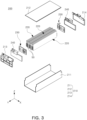
- FIG. 3 is an exploded perspective view of a battery module according to an exemplary embodiment.
- a battery pack 1 may include a pack housing 100 and a plurality of battery modules 200 disposed inside the pack housing 100.
- the pack housing 100 includes a pack frame 110 and a pack cover 120 coupled to an upper portion of the pack frame 110.
- the pack frame 110 includes a lower plate 111 and a side frame 112 extending upwardly from the lower plate 111.
- At least one partition 113 traversing an internal space of the pack housing 100 vertically or horizontally may be disposed on the lower plate 111.
- a partition 113a extending in the X direction and a partition 113b extending in the Y direction are disposed to divide the inside of the pack housing 100 into several compartments.
- At least one battery module 200 may be disposed in the space divided by the partition 113.
- four battery modules 200 are arranged in one compartment.
- a shape of the pack housing 100 and the number of battery modules 200 are examples, and the exemplary embodiment in the present disclosure is not limited thereto.
- the partition 113 may be disposed to form 7 or fewer or 9 or more compartments inside the pack.
- three or less or five or more battery modules 200 may be disposed in a single compartment.
- the battery module 200 includes a module case 210 and a plurality of battery cells accommodated in the module case 210.
- the module case 210 may be formed integrally or may be formed by coupling a plurality of cover plates.
- FIG. 1 shows a structure of the battery module 200
- the module case 210 having a structure surrounding the lower and both side surfaces of the battery cell 220, may include a lower cover plate 211 formed in an integral 'C' shape, an upper cover plate 212 covering an upper portion of the battery cell 220, a front cover plate 213 covering a front of the battery cell 220, and a rear cover plate covering a rear of the battery cell 220.
- the shape and size of the module case 210 are not particularly limited and may be appropriately selected according to the purpose, the shape and number of battery cells 220 accommodated in the internal space.
- the module case 210 performs a function of supporting and protecting the battery cells 220, and may perform a function of supporting and protecting the battery cell 220, cooling the battery cell 220 through water cooling or air cooling to protect the secondary battery from heat generated during charging and discharging of the battery module 200, and maintaining a temperature at an appropriate level.
- the module case 210 is preferably formed of a material having excellent thermal conductivity, may be formed of a metal material such as aluminum, gold, pure silver, tungsten, copper, nickel, or platinum, and preferably, aluminum, but is not limited thereto.
- the battery cells 220 accommodated in the module case 210 may be electrically connected to each other. Meanwhile, the number of battery cells 220 accommodated in the module case 210 may be adjusted according to purposes and is not particularly limited.
- the battery cell 220 may include an electrode assembly accommodated in a pouch-type casing, and the battery cell 220 according to the present disclosure may be used without limitation as long as it is commonly used.
- the electrode assembly may include a positive electrode including a positive electrode active material, a negative electrode including a negative electrode active material, and a separator, and the positive electrode may be manufactured by applying a mixture of a positive electrode active material, a conductive agent, and a binder on a positive electrode current collector and drying the applied mixture.
- the positive electrode current collector is not particularly limited as long as it has high conductivity without causing a chemical change in the battery.
- the positive electrode current collector may be formed of stainless steel, aluminum, nickel, titanium, sintered carbon, or aluminum, or may be formed of stainless steel surface-treated with carbon, nickel, titanium, silver, etc.
- the current collector may have fine irregularities on a surface thereof to increase an adhesive force of the positive electrode active material, and may have various forms such as a film, sheet, foil, net, porous body, foam body, and non-woven body.
- An internal busbar 230 electrically connected to the battery cell 220 may be included on a side from which an electrode lead of the battery cell 220 protrudes. Since the internal busbar 230 is formed on the side from which the electrode lead protrudes, the internal busbar may be formed on at least one of the front and rear sides of the battery cell.
- the internal busbar 230 may include a metal having excellent conductivity, for example, copper.
- the battery modules 200 are electrically connected to each other through an external busbar 300.
- the internal busbar 230 of the battery module 200 may be at least partially exposed externally of the module case 210 to be connected to the external busbar 300 connecting the battery modules 200 to each other.
- the battery module 200 may include an insulating cover 240 covering the internal busbar 230 in order to protect the internal busbar 230 and secure insulation.
- the insulating cover 240 may be coupled to the internal busbar 230 with each other or by a hook.
- the insulating cover 240 may be formed of one or more selected from the group consisting of modified polypropylene oxide (MPPO), polycarbonate (PC), polyethylene (PE), and polybutylene terephthalate (PBT). As described above, the insulating cover 240 may be covered by the front cover plate 213 and the rear cover plate 214 constituting the module case 210 to configure the battery module 200.
- MPPO modified polypropylene oxide
- PC polycarbonate
- PE polyethylene
- PBT polybutylene terephthalate
- the battery module 200 may include a first thermal propagation (TP) blocking member 50 disposed between cells among the plurality of battery cells 220.
- the first TP blocking member 50 may be formed of a material having at least one of high heat insulation, high heat resistance, and high fire resistance.
- the first TP blocking member 50 may be configured to minimize propagation of heat generated in one battery cell to other nearby battery cells.
- the first TP blocking member 50 may be disposed between battery cell groups including two or more battery cells.
- the first TP blocking member 50 may be alternately arranged with a battery cell group including four battery cells.
- the first TP blocking member 50 may be formed of a material including at least one of a polymer material, an inorganic material, and a ceramic material.
- the polymer material may include, for example, a material such as a silicone-based material.
- the inorganic material may include a material that does not contain carbon (C), for example, mica, lime, salt, silicon compounds such as glass, and some metals such as iron.
- the ceramic material may include a material formed of oxide, carbide, nitride, or the like formed as a metal element such as silicon (Si), aluminum (Al), titanium (Ti), zirconium (Zr) is combined with oxygen, carbon, nitrogen, and the like.
- Ceramic materials may be formed using natural raw materials, such as clay, kaolin, feldspar, silica, etc., or may be formed using a synthetic raw material such as silicon carbide, silicon nitride, alumina, zirconia, barium titanate, and the like.
- the first TP blocking member 50 may be coupled to the internal busbar 230.
- one end of the first TP blocking member 50 may be coupled to the internal busbar 230.
- the internal busbar 230 may be seated on an insulating plate, and the first TP blocking member 50 may be coupled to the insulating plate.
- gas inside the battery pack 1 may be discharged externally of the pack housing 100 through a vent portion 500 provided in the pack housing 100.
- the vent portion 500 includes a vent hole 510 connecting the inside and the outside of the pack housing 100.
- the gas may pass through the inside of the battery pack 1 and escape externally, without being ignited. Since the air inside the pack entirely escapes externally of the pack within a few seconds after thermal runaway, it may be difficult for a high-temperature and high-pressure gas ejected from the battery module 200 to mix with the air in an appropriate ratio, and accordingly, the gas may not be ignited or burnt and may be ejected externally of the pack 1.
- a speed at which gas is ejected externally of the battery pack 1 may be relatively fast, which may prevent flames from occurring outside the battery pack 1. This is because if the speed of the gas is high enough, the gas may not be sufficiently mixed with the external air, and thus, diffusion combustion may not occur. That is, the high-temperature gas inside the battery pack 1 may be ejected externally of the battery pack 1, without being ignited.
- the gas ejected after thermal runaway prevents the occurrence of flames due to a rapid increase in the gas concentration inside the battery pack 1, or the discharge amount of conductive particles may be reduced due to an increase in internal pressure, thereby preventing an external short circuit or ignition.
- a cross-sectional area of the vent hole 510 may be adjusted so that the gas generated in the battery cell is not ignited.
- the cross-sectional area of the vent hole 510 refers to an area of a plane, perpendicular to a gas discharge direction.
- the cross-sectional area of the vent hole 510 is (the ratio of the circumference of a circle to its diameter)*r 2 .
- a total cross-sectional area of the vent holes 510 may be greater than 1,000 mm 2 and less than or equal to 4,000 mm 2 .
- the cross-sectional area may be a cross-sectional area of an outer side of the vent hole 510 in contact with external air.
- two vent portions 500 are provided, but this is only an example, and one or three or more vent portions 500 may be provided.
- FIG. 4 illustrates a vent portion according to a first exemplary embodiment.
- FIG. 5 illustrates a vent portion according to a second exemplary embodiment.
- FIGS. 4 and 5 are cross-sectional views of the vent portion 500 taken along line II-II' in FIG. 2 .
- a cross-sectional area of the vent hole 510 of the battery pack 1 may be appropriately set according to the specifications of the battery pack 1.
- the amount of gas generated inside the battery pack 1 per unit time depends on the quantity and chemical composition of the battery module 200 (or battery cells 220) accommodated inside the battery pack 1, and thus, in order to control a gas exhaust rate according to a design intention, it may be necessary to form the vent hole 510 to have different cross-sectional areas in consideration of the above factors.
- the vent portion 500 may include a gas discharge unit 520.
- the gas discharge unit 520 having a large vent hole 530 may be selected.
- the gas discharge unit 520 having a small vent hole 530 may be selected.
- the vent hole 510 includes the vent hole 530.
- At least one gas discharge unit 520 may be provided and may be coupled to one surface of the side frame 112 in which the vent hole 510 is formed.
- the gas discharge unit 520 of the present exemplary embodiment may be detachably coupled to the side frame 112. Accordingly, the gas discharge unit 520 may be replaced by an operator as necessary.
- the gas discharge unit 520 may be formed in a square flat plate shape and has at least one vent hole 530 therein.
- the vent hole 530 is formed in the form of a through-hole and may be formed in a size smaller than the vent hole 510 of the side frame 112. Also, the gas discharge unit 520 may be coupled to the side frame 112 such that the vent hole 530 overlaps the vent hole 510.
- disposing the vent hole 530 to overlap the vent hole 510 refers to disposing the vent hole 530 such that at least a portion thereof is connected to the vent hole 510.
- the gas discharge unit 520 may be coupled to the side frame 112 through a separate fixing member such as a screw or bolt. To this end, the gas discharge unit 520 and the side frame 112 may have a fastening hole into which a fixing member is inserted. However, the present disclosure is not limited thereto, and various members may be used as long as the gas discharge unit 520 may be firmly coupled to one surface of the side frame 112.
- the operator may select the gas discharge unit 520 in which the vent hole 530 having a suitable size is formed as needed and couple the gas discharge unit 520 to the side frame 112.
- the gas discharge units 520a and 520b may include vent holes 530a and 530b having different sizes, respectively.
- the size of the vent hole 530 may be defined in consideration of a type of battery cells accommodated in the battery pack 1 or a size of the internal space of the side frame 112.
- the operator may selectively couple only the gas discharge unit 520 to the pack housing 100 having the same shape, thereby completing the battery pack 1 including a gas outlet having a desired size.
- a plurality of gas discharge units 520 may be provided.
- two or more gas discharge units 520a and 520b may be coupled to the battery pack 1.
- a first gas discharge unit 520a is coupled to an inner surface of the side frame 112
- a second gas discharge unit 520b is coupled to an outer surface of the side frame 112.
- the battery pack 1 does not include the gas discharge unit 520, pack housings in which gas outlets of various sizes are formed to correspond to the various battery cells 220 or the various battery modules 200 should be provided. In this case, the manufacturing costs may increase significantly.
- the pack housings may be manufactured collectively, which may minimize manufacturing costs.
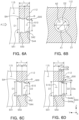
- FIG. 6A to FIG. 6D show a vent portion according to a third exemplary embodiment.
- FIG. 7A and FIG. 7B show a vent portion according to a fourth exemplary embodiment.
- FIG. 6A to FIG. 7B are cross-sectional views of the vent portion 500 taken along line II-II' in FIG. 2 .
- the vent portion 500 may have a structure in which a cross-sectional area A2 of an outlet side 542 connected to the external space of the pack housing 100 may be smaller than a cross-sectional area A1 of an inlet side 541 connected to the internal space 115.
- the cross-sectional area A2 of the outlet side 542 is formed to be smaller than the cross-sectional area A1 of the inlet side 541, the air outside the pack housing 100 is difficult to be introduced into the internal space 115 through the vent portion 500.
- vent portion 500 may effectively block inflow of external air (oxygen) without excessively increasing the pressure increase inside the battery pack 1.
- the vent portion 500 may be provided in a form in which a cross-sectional area thereof decreases from the inside of the pack externally of the pack.
- the vent portion 500 may include a first region 543 connected to the inlet side 541 and having a relatively large cross-sectional shape and a second region 544 connected to the outlet side 542 and having a relatively small cross-sectional shape compared to the first region 543.
- an average cross-sectional area of the second region 544 may be smaller than that of the first region 543.
- first region 543 may extend from the inlet side 541 to the outlet side 542 in the same cross-sectional shape
- the second region 544 may extend to the outlet side 542 in a form in which a cross-sectional area thereof decreases, compared to the first region 543.
- first region 543 and the second region 544 may each have a circular cross-sectional shape as illustrated in FIG. 6B .
- a diameter D1 of the inlet side 541 has a larger shape than a diameter D2 of the outlet side 542.
- the first region 543 and the second region 544 each have a circular cross-sectional shape
- the first region 543 of the vent portion 500 may have a hollow cylindrical shape with a constant diameter D1
- the second region 544 may have a hollow truncated cone shape having diameter decreasing toward the outlet side 542.
- a boundary region BA in which a cross-sectional structure is changed may be formed between the first region 543 and the second region 544.
- the boundary region BA between the first region 543 and the second region 544 may be formed in a prismatic shape as illustrated in FIGS. 6A and 7B .
- the boundary region BA between the first region 543 and the second region 544 may be connected to have a gentle curve as illustrated in FIGS. 6C and 7A .
- the second region 544 may be inclined at a single inclination angle ⁇ as illustrated in FIGS. 6A, 6C , 7A, and 7B or may have a structure in which the second region 544 is divided into two or more zones 544a and 544b in which inclination angles ⁇ a and ⁇ b in the respective regions are changed as illustrated in FIG. 6D .
- the inclination angle ⁇ b in the zone 544b close to the outlet side 542 may be formed to be greater than the inclination angle ⁇ a in the zone 544a farther from the outlet side 542 so that the diameter D2 of the outlet side 542 is smaller than a diameter D2a of a portion located in the central portion of the second region 544.
- the vent portion 500 when the vent portion 500 has a circular cross-section, the possibility of vortex or turbulence occurring in the air flowing inside the vent portion 500 may be reduced, compared to ab prismatic cross-section, and thus, smooth flow from the inlet side 541 to the outlet side 542 may be formed.
- the cross-sectional shape of the vent portion 500 may be variously modified to an oval cross-section or the like, and does not exclude a prismatic cross-sectional structure.
- the vent portion 500 may have a structure in which an inclination angle is formed in both the first region 543 and the second region 544.
- the first region 543 may have a shape in which the cross-sectional area decreases with a first inclination angle with respect to the length direction of the vent portion 500
- the second region 544 may have a shape in which the cross-sectional area decreases with a second inclination angle greater than the first inclination angle with respect to the length direction of the vent portion 500.
- a length L2 of the second region 544 may be 0.2 to 0.8 times a distance from the inlet side 541 to the outlet side 542, that is, a total length L of the vent portion 500. If the length L2 of the second region 544 is less than 0.2 times the total length L, the length L2 of the second region 544 may be excessively shortened. Accordingly, a possibility of introducing external air through the shortened second region 544 may be increased, and thus, an installation effect of the second region 544 may be reduced. Conversely, if the length L2 of the second region 544 exceeds 0.8 times the total length L, the length L1 of the first region 543 may be excessively short.
- the second region 544 having a small cross-sectional area is formed to be long, gas may not be smoothly discharged from the internal space 115 through the second region 544, and accordingly, pressure in the internal space 115 of the battery pack 1 may be increased.
- the cross-sectional area A2 of the outlet side 542 may be 0.2 to 0.8 times the cross-sectional area A1 of the inlet side 541. If the cross-sectional area A2 of the outlet side 542 is less than 0.2 times the cross-sectional area A1 of the inlet side, the cross-sectional area A2 of the outlet side 542 may be excessively small so that gas in the internal space 115 of the battery pack 1 may not be smoothly discharged, causing a problem in that pressure inside the battery pack 1 increases.
- the cross-sectional area A2 of the outlet side 542 may be 0.4 to 0.7 times the cross-sectional area A1 of the inlet side 541.
- the effect of smoothly discharging the gas in the internal space 115 of the battery pack 1 externally and the effect of minimizing inflow of external air using a difference between the cross-sectional areas of the inlet side 541 and the outlet side 542 may be sufficiently achieved.
- specific values of the cross-sectional area A1 of the inlet side 541 of the vent portion 500, the cross-sectional area A2 of the outlet side 542, the length L1 of the first region 543, and the length L2 of the second region 544 may be determined according to a volume of the internal space 115 of the battery pack 1 and the position and shape of the vent hole.
- FIGS. 1 to 4 only a case in which the vent portion 500 has the first region 543 and the second region 544 is illustrated, but it is also possible to provide a third region having a cross-sectional shape according to the length direction of the vent portion 500, different from those of the first region 543 and the second region 544, between the first region 543 and the second region 544. That is, a third region having a value between the average cross-sectional area of the first region 543 and the average cross-sectional area of the second region 544 may be provided between the first region 543 and the second region 544.
- the vent portion 500 may be formed in the shape of a hole in the side frame 112 of the pack housing 100 when an outer wall of the pack housing 100 has a sufficient thickness. That is, as illustrated in FIG. 6A , the vent portion 500 may be formed by machining a hole in which the diameter D1 of the inlet side 541 is greater than the diameter D2 of the outlet side 542 in the side frame 112 of the pack housing 100.
- the vent portion 500 may protrude outwardly of the side frame 112 of the pack housing 100 as illustrated in FIGS. 7A and 7B .
- the vent portion 500 may have a structure protruding outwardly of the pack housing 100 by 28 mm.
- the vent portion 500 may include a venting guide member 546 attached to the side frame 112 of the pack housing 100.
- the venting guide member 546 may have a shape in which the first region 543 and the second region 544 are formed, as illustrated in FIG. 7A .
- the venting guide member 546 may be mounted on an inner surface of a hole formed in the pack housing 100 and matches with the inner surface of the side frame 112.
- the venting guide member 546 may have a shape in which only a partial region of the vent portion 500 is formed, as illustrated in FIG. 7B .
- the venting guide member 545 may have a shape attached to an outer surface of the side frame 112 of the venting guide member 545.
- the inlet side 541 may be positioned on the same line as the inner surface of the side frame 112 of the pack housing 100. If the inlet side 541 of the vent portion 500 has a pipe shape protruding inwardly of the inner surface of an outer wall of the pack housing 100, an eddy current or turbulence may occur in the circumference of the inlet side 541 protruding into the internal space 115 in a pipe shape. For example, assuming that the venting guide member 546 has a shape extending to the left in FIG.
- a phenomenon e.g., a vortex in which air flowing along the inner surface of the outer wall of the pack housing 100 does not flow directly into the inlet of the venting guide member but a flow thereof is not uniform occurs.
- gas in the internal space 115 may flow along the inner surface of side frame 112 and easily flow to the inlet side 541 of the vent portion 500 to be discharged externally, thereby effectively improving the flow of gas discharged from the pack housing 100.
- FIG. 8 is an internal cross-sectional view of a battery pack according to an exemplary embodiment.
- FIG. 9 is an internal cross-sectional view of a battery pack in which a battery module and a pack cover are coupled to an adhesive member according to an exemplary embodiment.
- FIG. 10 is an internal cross-sectional view of a battery pack in which a battery module and a pack cover are mechanically coupled according to an exemplary embodiment.
- FIGS. 8 to 10 are cross-sectional views taken along line I-I' of the battery pack 1 in FIG. 1 .
- a gap between the battery module 200 and the pack cover 120 may be provided to be relatively small.
- the gap d between the battery module 200 and the pack cover 120 may be set to 100 mm or less. That is, an air layer having a thickness of 100 mm or less may be formed between the battery module 200 and the pack cover 120.
- the air layer may be defined as a space between the pack cover 120 and the module case 210.
- the gap d between the battery module 200 and the pack cover 120 is large, gas generated during thermal runaway may move to the corresponding gap d, thereby reducing a gas exhaust rate from the vent hole.
- the pack cover 120 is positioned closer to the module case 210, the volume of the empty space inside the battery pack 1 may be reduced, the internal pressure of the battery pack 1 may be quickly increased during thermal runaway, which may increase a gas ejection rate. Ignition of the gas may be prevented according to the increase of the gas ejection rate.
- the air inside the pack may be discharged externally within a relatively short time, which may prevent the premixed combustion of gas.
- the air When air is introduced into the battery pack 1, the air may be mixed with the high-temperature and high-pressure gas discharged from the battery cell, which may lead to an occurrence of combustion and flames. Therefore, it is important to seal the inside and outside of the battery pack 1.
- the gas ejection rate from the vent portion 500 may be lowered and the gas may be ignited.
- a sealing member 400 may be disposed between the pack cover 120 and the pack frame 110.
- the pack frame 110 may include a lower plate 111 disposed below the plurality of battery modules 200 and a side frame 112 extending upwardly from the lower plate 111, and the side frame 112 may be provided in the form of a side wall surrounding the plurality of battery modules 200.
- the sealing member 400 may be disposed between the side frame 112 and the pack cover 120. For example, when the edge of the pack cover 120 is seated on a top surface of the side frame 112, the sealing member 400 may be applied between the edge of the pack cover 120 and the top surface of the side frame 112.
- the entirety or most portion of the gas occurring inside the pack housing 100 may be discharged externally of the housing through the vent portion 500, thereby ensuring a relatively high discharge rate.
- combustion of gas inside the pack may be prevented or minimized.
- the sealing member 400 may include a fire resistant material or a heat resistant material. Accordingly, even if a high-temperature gas or flame occurs inside the pack, damage to the sealing member 400 may be prevented or minimized, and further, sealing between the pack frame 110 and the pack cover 120 may be maintained.
- the pack cover 120 may be deformed and the gap d between the battery module 200 and the pack cover 120 may be increased.
- the pack cover 120 may be fixedly coupled to the battery module 200.
- the pack cover 120 may be fixedly coupled to some or all of the plurality of battery modules 200 disposed inside the pack housing 100.
- an adhesive member 251 may be attached between the module case 210 and the pack cover 120.
- the adhesive member 251 may include a material having excellent heat dissipation characteristics, such as thermal resin.
- the battery module 200 and the pack cover 120 may be mechanically coupled.
- the module case 210 and the pack cover 120 may be coupled by a bolt 252.
- the gap d between the battery module 200 and the pack cover may be maintained at a certain level.
- rigidity of the pack housing 100 should be improved in order to secure the gas exhaust rate. Due to the gas occurring inside the pack housing 100, the internal pressure of the pack housing 100 may increase, and accordingly, the pack housing 100 may be deformed to be cracked. For example, a gap may be formed between the pack frame 110 and the pack cover 120. In this case, the gas exhaust rate through the vent portion 500 may be slowed, so that the gas discharged externally of the pack may be ignited. In addition, air may be introduced from the outside of the pack housing 100 to the inside, which may burn the gas to accelerate heat propagation inside the battery pack 1.
- the pack cover 120 may be formed of a material with high rigidity.
- the pack cover 120 may be formed of a steel material.
- the rigidity of the pack cover 120 increases, deformation of the pack cover 120 may be suppressed, which may contribute to preventing inflow of external air into the pack housing 100 or quickly escaping of gas occurring inside the housing externally through the vent portion 500. That is, as the rigidity of the pack cover 120 is improved, even if a large amount of gas occurs inside the battery pack 1, the gas may be rapidly discharged through the vent portion 500, and external air may be prevented from flowing into the battery pack 1 to delay heat propagation inside the battery pack 1.
- FIG. 11 illustrates an external busbar and a cover member according to an exemplary embodiment.
- the battery pack 1 including the plurality of battery modules 200, when any one battery module 200 thermally runs, gas, flames, as well as conductive particles, may be discharged.
- the module case 210 or the pack housing 100 may include a conductive material such as aluminum, and the external busbar 300 is disposed at a predetermined distance from the module case 210 or the pack housing 100.
- a gas containing conductive particles surrounds the periphery of the external busbar 300, an insulation distance between the external busbar 300 and the module case 210 (or the pack housing 100) is shortened, which may cause a short circuit between the external busbar and the module case 210 (or the pack housing 100). Due to this, thermal runaway may spread to other battery modules inside the battery pack 1. Accordingly, exposure of the external busbar 300 to conductive particles in a thermal runaway situation should be minimized.
- the external busbar 300 may be surrounded by the cover member 310 so as not to be exposed to conductive particles.
- the cover member 310 may be configured to prevent or minimize contact between the external busbar 300 and the conductive particles.
- the cover member 310 may be provided to cover at least a portion of the surface of the external busbar 300.
- the cover member 310 may be formed of a flame-retardant material or a fire-resisting insulating material.
- the cover member 310 may be formed of a material that is not melted or ignited below 1000 degrees Celsius.
- the cover member 310 may include a silicon or mica material.
- the cover member 310 may be formed of a material having electrical insulating properties, such as resin.
- the cover member 310 may be formed of a material having heat resistance performance capable of maintaining a shape at a high temperature.
- the cover member 310 may be formed of a resin material or a fiber composite material having heat resistance performance of 150°C or higher.
- the cover member 310 may include a resin or a fiber composite material primarily covering the surface of the external busbar 300 and a flame retardant material (e.g., silicone or mica) secondarily covering the surface of the resin or fiber composite material.
- a flame retardant material e.g., silicone or mica
- FIG. 12 illustrates a second TP blocking member 60 covering the outside of the battery module 200 in an exemplary embodiment.
- the second TP blocking member 60 may be disposed between the battery module 200 and the pack cover 120. When a fire occurs in the battery module 200, gas, flames, dust, and conductive particles may spread to the space inside the battery pack. In an exemplary embodiment, the second TP blocking member 60 may be disposed in at least a portion of the outer surface of the battery module 200, so that the battery module 200 may be protected from flames or gas ejected from the other battery module 200, which may prevent a chain ignition or thermal runaway.
- the second TP blocking member 60 may be formed of a flame-retardant material or a fire-resisting insulating material capable of blocking the propagation of flames.
- the second TP blocking member 60 may be formed of a material that does not melt or ignite below 1000 degrees Celsius.
- the second TP blocking member 60 may be formed by forming a plate having a thickness of 1 mm or more.
- the configuration of the present disclosure is not limited thereto.
- the second TP blocking member 60 may be formed to cover an upper portion and a side portion of the battery module 200.
- the second TP blocking member 60 may be coupled to each battery module 200 in the form of at least partially covering the battery module 200 to suppress the spread of flames or conductive particles.
- the second TP blocking member 60 may include a top cover 61 disposed at an upper portion of the battery module 200 and a side cover 62 extending from the top cover 61 to face both side surfaces of the battery module 200.
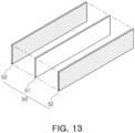
- FIG. 13 is an example of a TP blocking member disposed between battery cells according to an exemplary embodiment.
- the first TP blocking member 50 may include a heat resistant sheet 51 and a pad 52 disposed on at least one surface of the heat resistant sheet 51.
- the heat resistant sheet 51 may include a material having excellent heat resistance and/or fire resistance.
- the heat resistant sheet 51 may include mica. Since the heat resistant sheet 51 maintains its original shape relatively well even in high heat or flames, the first TP blocking member 50 may block or delay heat transfer more stably.
- the pad 52 may be formed of an elastically deformable material. Since the heat resistant sheet 51 has relatively high rigidity, if the heat resistant sheet 51 directly touches the battery cells, the battery cells may be damaged.
- the pad 52 may be disposed on the battery cell together with the heat resistant sheet 51 and may be compressed when the battery cells are pressed against each other in a stacking direction. Accordingly, the pad 52 may prevent damage to the battery cells and make a pressing force applied to one surface of the battery cells uniform. For example, if a portion of a battery cell becomes convex due to swelling, stress may be concentrated in the corresponding portion, and in this case, the pad 52 may be compressed in response to the deformation of the battery cell and may make the pressure applied to one surface of the battery cell uniform.
- the pad 52 may include a material having a relatively lower thermal conductivity than the heat resistant sheet 51.
- the pad 52 may be formed of a material having a thermal conductivity of 0.1 W/(m ⁇ K) or less when measured according to the ISO 22007 standard.
- the pad 52 includes an insulating material.
- insulation resistance of the pad 52 when measured according to ASTM D257 standard, may be 500 megaohms (M ⁇ ) or more.
- a battery pack having high safety may be provided.
- high-temperature flammable gas occurring due to thermal runaway of the battery pack may be discharged externally as quickly as possible without ignition, which may delay or suppress thermal runaway or heat propagation inside the battery pack.
- a safer battery pack in which flammable gas occurring is ejected externally of the pack without being ignited, may be provided.
Landscapes
- Chemical & Material Sciences (AREA)
- Chemical Kinetics & Catalysis (AREA)
- Electrochemistry (AREA)
- General Chemical & Material Sciences (AREA)
- Engineering & Computer Science (AREA)
- Manufacturing & Machinery (AREA)
- Inorganic Chemistry (AREA)
- Battery Mounting, Suspending (AREA)
Abstract
Description
- The present disclosure relates to a battery pack.
- A secondary battery, referring to a battery that may be charged and discharged, unlike a primary battery that cannot be charged, has been applied to electric vehicles (EVs), hybrid electric vehicles (HEVs), and the like, driven by an electrical motive power source, as well as portable devices.
- Lithium ion batteries, lithium polymer batteries, nickel cadmium batteries, nickel hydrogen batteries, nickel zinc batteries or the like have been widely used as secondary batteries. Such a unit secondary battery cell, i.e., a unit battery cell, has an operating voltage of about 2.5V to 4.6V. Therefore, if a higher output voltage is demanded, a plurality of secondary battery cells may be connected in series to configure a battery pack. In addition, according to a charge/discharge capacity required for the battery pack, a plurality of battery cells may also be connected in parallel to configure a battery pack. Therefore, the number of secondary battery cells included in the battery pack may be set to be various, depending on a required output voltage or charge/discharge capacity.
- Types of secondary batteries currently widely used include lithium ion batteries, lithium polymer batteries, nickel cadmium batteries, nickel hydrogen batteries, nickel zinc batteries, and the like. The unit secondary battery cell, that is, the operating voltage of the unit battery cell is about 2.5V to 4.6V. Accordingly, when a higher output voltage is required, a plurality of battery cells are connected in series to form a battery pack. In addition, a plurality of battery cells may be connected in parallel to form a battery pack according to the charge/discharge capacity required for the battery pack. Accordingly, the number of battery cells included in the battery pack may be variously set according to a required output voltage or charge/discharge capacity.
- When a specific battery cell or battery module malfunctions in a battery pack including a plurality of battery cells or battery modules, gas or conductive particles may be ejected into the pack, which may affect other battery cells or battery modules to cause a chain of thermal runaway. When the battery pack is mounted in a vehicle, thermal runaway of the battery pack may threaten the life of a driver or passengers, and thus, a method for preventing or delaying thermal runaway is required.
- Exemplary embodiments provide a battery pack having a high degree of safety. In particular, exemplary embodiments provide a structure capable of discharging high-temperature flammable gas, caused by thermal runaway of a battery pack, externally as quickly as possible without ignition.
- Exemplary embodiments provide a multilayer electronic component provide a multilayer electronic component including a uniform plating layer.
- According to an aspect of the present disclosure, a battery pack includes: a pack housing; at least one battery module disposed inside the pack housing; and a vent hole connecting inside and outside of the pack housing, wherein the battery module includes a plurality of battery cells and a first thermal propagation (TP) blocking member disposed between the plurality of battery cells.
- The battery pack may further include: an internal busbar coupled to the plurality of battery cells, wherein the first TP blocking member may be coupled to the internal busbar.
- The pack housing may include a pack cover covering an upper portion of the battery module, and a second TP blocking member may be disposed between the upper portion of the battery module and the pack cover.
- The second TP blocking member may be formed to surround an upper portion and a side portion of the battery module.
- A total cross-sectional area of the vent hole may be greater than 1,000 mm2 and less than or equal to 4,000 mm2.
- An air layer having a thickness of 100 mm or less may be formed between the at least one battery module and the pack cover.
- The at least one battery module may include a plurality of battery cells and a module case accommodating the plurality of battery cells, and the air layer may be defined as a space between the pack cover and the module case.
- The vent hole may be formed so that a cross-sectional area of an outlet side connected to an external space of the pack housing is smaller than a cross-sectional area of an inlet side connected to the internal space of the pack housing.
- At least a portion of the vent hole may have a cross-sectional area decreasing from the inlet side to the outlet side.
- The pack cover may include a steel material.
- In an exemplary embodiment, the pack housing may include a side frame surrounding the at least one battery module, and a sealing member may be disposed between the side frame and the pack cover.
- The battery pack may further include an external busbar electrically connecting at least two battery modules to each other; and a cover member surrounding a surface of the external busbar.
- The cover member may include a fire resistant material or an insulating material. The first TP blocking member may include a heat resistant sheet and a pad disposed on at least one surface of the heat resistant sheet and formed of a material that is elastically deformed. The pad may have a thermal conductivity of 0.1 W/(m·K) or less. The pad may have an insulation resistance of 500 MΩ or more. The heat resistant sheet may include mica.
- The above and other aspects, features, and advantages of the present disclosure will be more clearly understood from the following detailed description, taken in conjunction with the accompanying drawings, in which:
-
FIG. 1 is a perspective view of a battery pack according to an exemplary embodiment; -
FIG. 2 is an exploded perspective view of a battery pack according to an exemplary embodiment; -
FIG. 3 is an exploded perspective view of a battery module according to an exemplary embodiment; -
FIG. 4 illustrates a vent portion according to a first exemplary embodiment; -
FIG. 5 illustrates a vent portion according to a second exemplary embodiment; -
FIG. 6A to FIG. 6D show a vent portion according to a third exemplary embodiment; -
FIG. 7A and FIG. 7B show a vent portion according to a fourth exemplary embodiment; -
FIG. 8 is an internal cross-sectional view of a battery pack according to an exemplary embodiment; -
FIG. 9 is an internal cross-sectional view of a battery pack in which a battery module and a pack cover are coupled to an adhesive member according to an exemplary embodiment; -
FIG. 10 is an internal cross-sectional view of a battery pack in which a battery module and a pack cover are mechanically coupled according to an exemplary embodiment; -
FIG. 11 illustrates an external busbar and a cover member according to an exemplary embodiment; -
FIG. 12 illustrates a TP blocking member surrounding the outside of a battery module according to an exemplary embodiment; and -
FIG. 13 is an example of a TP blocking member disposed between battery cells according to an exemplary embodiment. - The terms used in the following description and claims are widely used common expressions selected by considering functions in various embodiments of the present disclosure. However, such terms may vary depending upon an intention of a person having ordinary skill in the art (hereinafter referred to as 'those skilled in the art'), legal/technical interpretations, or advent of new technologies. Some of the terms were selected arbitrarily by an applicant, and the terms may be interpreted as defined herein. Unless otherwise defined, the terms may be interpreted based on overall descriptions of the present disclosure and common technical knowledge in the art.
- In the following description, like drawing reference numerals and symbols refer to the like elements which perform substantially the same function, even in different drawings, for convenience in explanation and for better understanding. That is, although a plurality of drawings share elements having the same reference numerals, the plurality of drawings do not relate to one embodiment.
- In the following description and claims, a term including an ordinal, such as, 'first' or 'second,' may be used to distinguish elements. The ordinal is used to distinguish the same or similar elements and does not limit the meaning of the term. For instance, ordinals do not affect an order of use or an order of arrangement of elements expressed with the ordinals. Respective ordinals may be replaced with each other, if necessary.
- A term in a singular form includes a plural form unless it is intentionally written that way. That is, even if a component is expressed in a singular form in this document, it should not be construed as excluding that the corresponding component is provided in plural unless otherwise specified. For example, when it is assumed that a first member is disposed on a frame in an embodiment, the embodiment is not limited to a case in which only one first member disposed on the frame but should be understood as including a case in which two or more first members are disposed on the frame.
- A term, such as, 'include' or 'form,' refers to the disclosed features, numbers, steps, operations, elements, parts, or combinations thereof and is not intended to exclude any possibilities of existence or addition of one or more other features, numbers, steps, operations, elements, parts, or combinations thereof.
- In this document, the X-direction, Y-direction, and Z-direction mean a direction parallel to the X-axis, a direction parallel to the Y-axis, and a direction parallel to the Z-axis illustrated in the drawings, respectively. In addition, unless otherwise specified, the X-direction is a concept including both the +X-axis direction and the -X-axis direction, which is also applied to the Y-direction and the Z-direction.
-
FIG. 1 is a perspective view of a battery pack according to an exemplary embodiment.FIG. 2 is an exploded perspective view of a battery pack according to an exemplary embodiment.FIG. 3 is an exploded perspective view of a battery module according to an exemplary embodiment. - Referring to
FIGS. 1 and2 , in an exemplary embodiment, abattery pack 1 may include apack housing 100 and a plurality ofbattery modules 200 disposed inside thepack housing 100. - The
pack housing 100 includes apack frame 110 and apack cover 120 coupled to an upper portion of thepack frame 110. Thepack frame 110 includes alower plate 111 and aside frame 112 extending upwardly from thelower plate 111. - At least one
partition 113 traversing an internal space of thepack housing 100 vertically or horizontally may be disposed on thelower plate 111. In the illustrated exemplary embodiment, apartition 113a extending in the X direction and apartition 113b extending in the Y direction are disposed to divide the inside of thepack housing 100 into several compartments. - At least one
battery module 200 may be disposed in the space divided by thepartition 113. In the illustrated exemplary embodiment, fourbattery modules 200 are arranged in one compartment. Meanwhile, a shape of thepack housing 100 and the number ofbattery modules 200 are examples, and the exemplary embodiment in the present disclosure is not limited thereto. For example, thepartition 113 may be disposed to form 7 or fewer or 9 or more compartments inside the pack. As another example, three or less or five ormore battery modules 200 may be disposed in a single compartment. - Referring to
FIG. 3 , in an exemplary embodiment, thebattery module 200 includes amodule case 210 and a plurality of battery cells accommodated in themodule case 210. - The
module case 210 may be formed integrally or may be formed by coupling a plurality of cover plates. For example,FIG. 1 shows a structure of thebattery module 200, and themodule case 210, having a structure surrounding the lower and both side surfaces of thebattery cell 220, may include alower cover plate 211 formed in an integral 'C' shape, anupper cover plate 212 covering an upper portion of thebattery cell 220, afront cover plate 213 covering a front of thebattery cell 220, and a rear cover plate covering a rear of thebattery cell 220. The shape and size of themodule case 210 are not particularly limited and may be appropriately selected according to the purpose, the shape and number ofbattery cells 220 accommodated in the internal space. - The
module case 210 performs a function of supporting and protecting thebattery cells 220, and may perform a function of supporting and protecting thebattery cell 220, cooling thebattery cell 220 through water cooling or air cooling to protect the secondary battery from heat generated during charging and discharging of thebattery module 200, and maintaining a temperature at an appropriate level. Accordingly, themodule case 210 is preferably formed of a material having excellent thermal conductivity, may be formed of a metal material such as aluminum, gold, pure silver, tungsten, copper, nickel, or platinum, and preferably, aluminum, but is not limited thereto. - The
battery cells 220 accommodated in themodule case 210 may be electrically connected to each other. Meanwhile, the number ofbattery cells 220 accommodated in themodule case 210 may be adjusted according to purposes and is not particularly limited. - Meanwhile, the
battery cell 220 may include an electrode assembly accommodated in a pouch-type casing, and thebattery cell 220 according to the present disclosure may be used without limitation as long as it is commonly used. For example, the electrode assembly may include a positive electrode including a positive electrode active material, a negative electrode including a negative electrode active material, and a separator, and the positive electrode may be manufactured by applying a mixture of a positive electrode active material, a conductive agent, and a binder on a positive electrode current collector and drying the applied mixture. The positive electrode current collector is not particularly limited as long as it has high conductivity without causing a chemical change in the battery. For example, the positive electrode current collector may be formed of stainless steel, aluminum, nickel, titanium, sintered carbon, or aluminum, or may be formed of stainless steel surface-treated with carbon, nickel, titanium, silver, etc. The current collector may have fine irregularities on a surface thereof to increase an adhesive force of the positive electrode active material, and may have various forms such as a film, sheet, foil, net, porous body, foam body, and non-woven body. - An
internal busbar 230 electrically connected to thebattery cell 220 may be included on a side from which an electrode lead of thebattery cell 220 protrudes. Since theinternal busbar 230 is formed on the side from which the electrode lead protrudes, the internal busbar may be formed on at least one of the front and rear sides of the battery cell. Theinternal busbar 230 may include a metal having excellent conductivity, for example, copper. - Referring to
FIGS. 1 to 3 , thebattery modules 200 are electrically connected to each other through anexternal busbar 300. Theinternal busbar 230 of thebattery module 200 may be at least partially exposed externally of themodule case 210 to be connected to theexternal busbar 300 connecting thebattery modules 200 to each other. - The
battery module 200 may include an insulatingcover 240 covering theinternal busbar 230 in order to protect theinternal busbar 230 and secure insulation. The insulatingcover 240 may be coupled to theinternal busbar 230 with each other or by a hook. The insulatingcover 240 may be formed of one or more selected from the group consisting of modified polypropylene oxide (MPPO), polycarbonate (PC), polyethylene (PE), and polybutylene terephthalate (PBT). As described above, the insulatingcover 240 may be covered by thefront cover plate 213 and therear cover plate 214 constituting themodule case 210 to configure thebattery module 200. - In an exemplary embodiment, the
battery module 200 may include a first thermal propagation (TP) blockingmember 50 disposed between cells among the plurality ofbattery cells 220. The firstTP blocking member 50 may be formed of a material having at least one of high heat insulation, high heat resistance, and high fire resistance. The firstTP blocking member 50 may be configured to minimize propagation of heat generated in one battery cell to other nearby battery cells. - In an exemplary embodiment, the first
TP blocking member 50 may be disposed between battery cell groups including two or more battery cells. For example, referring toFIG. 3 , the firstTP blocking member 50 may be alternately arranged with a battery cell group including four battery cells. - The first
TP blocking member 50 may be formed of a material including at least one of a polymer material, an inorganic material, and a ceramic material. Here, the polymer material may include, for example, a material such as a silicone-based material. Also, the inorganic material may include a material that does not contain carbon (C), for example, mica, lime, salt, silicon compounds such as glass, and some metals such as iron. The ceramic material may include a material formed of oxide, carbide, nitride, or the like formed as a metal element such as silicon (Si), aluminum (Al), titanium (Ti), zirconium (Zr) is combined with oxygen, carbon, nitrogen, and the like. These ceramic materials may be formed using natural raw materials, such as clay, kaolin, feldspar, silica, etc., or may be formed using a synthetic raw material such as silicon carbide, silicon nitride, alumina, zirconia, barium titanate, and the like. - In an exemplary embodiment, the first
TP blocking member 50 may be coupled to theinternal busbar 230. For example, one end of the firstTP blocking member 50 may be coupled to theinternal busbar 230. In another exemplary embodiment, theinternal busbar 230 may be seated on an insulating plate, and the firstTP blocking member 50 may be coupled to the insulating plate. - Meanwhile, gas inside the
battery pack 1 may be discharged externally of thepack housing 100 through avent portion 500 provided in thepack housing 100. Thevent portion 500 includes avent hole 510 connecting the inside and the outside of thepack housing 100. - If the gas generated in the
battery pack 1 is discharged externally too slowly or if too much gas is discharged at once, flames may occur outside thebattery pack 1. Therefore, it is advantageous to discharge the gas occurring in thebattery pack 1 externally of thebattery pack 1 at an appropriate rate. - According to the exemplary embodiments described below, even if flammable gas is ejected from the
battery module 200, the gas may pass through the inside of thebattery pack 1 and escape externally, without being ignited. Since the air inside the pack entirely escapes externally of the pack within a few seconds after thermal runaway, it may be difficult for a high-temperature and high-pressure gas ejected from thebattery module 200 to mix with the air in an appropriate ratio, and accordingly, the gas may not be ignited or burnt and may be ejected externally of thepack 1. - According to an exemplary embodiment, by appropriately setting a size of the
vent hole 510, a speed at which gas is ejected externally of thebattery pack 1 may be relatively fast, which may prevent flames from occurring outside thebattery pack 1. This is because if the speed of the gas is high enough, the gas may not be sufficiently mixed with the external air, and thus, diffusion combustion may not occur. That is, the high-temperature gas inside thebattery pack 1 may be ejected externally of thebattery pack 1, without being ignited. - According to an exemplary embodiment, the gas ejected after thermal runaway prevents the occurrence of flames due to a rapid increase in the gas concentration inside the
battery pack 1, or the discharge amount of conductive particles may be reduced due to an increase in internal pressure, thereby preventing an external short circuit or ignition. - In an exemplary embodiment, a cross-sectional area of the
vent hole 510 may be adjusted so that the gas generated in the battery cell is not ignited. The cross-sectional area of thevent hole 510 refers to an area of a plane, perpendicular to a gas discharge direction. For example, when thevent hole 510 is provided in the form of a circular pipe having an inner radius of r, the cross-sectional area of thevent hole 510 is (the ratio of the circumference of a circle to its diameter)*r2. In an exemplary embodiment, when one or more vent portions 500 (or vent holes 510) are provided, a total cross-sectional area of the vent holes 510 may be greater than 1,000 mm2 and less than or equal to 4,000 mm2. In this case, the cross-sectional area may be a cross-sectional area of an outer side of thevent hole 510 in contact with external air. In the illustrated exemplary embodiment, twovent portions 500 are provided, but this is only an example, and one or three ormore vent portions 500 may be provided. -
FIG. 4 illustrates a vent portion according to a first exemplary embodiment.FIG. 5 illustrates a vent portion according to a second exemplary embodiment.FIGS. 4 and 5 are cross-sectional views of thevent portion 500 taken along line II-II' inFIG. 2 . - Referring to
FIGS. 4 and 5 , in an exemplary embodiment, a cross-sectional area of thevent hole 510 of thebattery pack 1 may be appropriately set according to the specifications of thebattery pack 1. The amount of gas generated inside thebattery pack 1 per unit time depends on the quantity and chemical composition of the battery module 200 (or battery cells 220) accommodated inside thebattery pack 1, and thus, in order to control a gas exhaust rate according to a design intention, it may be necessary to form thevent hole 510 to have different cross-sectional areas in consideration of the above factors. - In an exemplary embodiment, the
vent portion 500 may include agas discharge unit 520. For example, when the amount of gas generated per unit time is large, thegas discharge unit 520 having alarge vent hole 530 may be selected. On the contrary, when the amount of gas generated per unit time is small, thegas discharge unit 520 having asmall vent hole 530 may be selected. In this case, thevent hole 510 includes thevent hole 530. - At least one
gas discharge unit 520 may be provided and may be coupled to one surface of theside frame 112 in which thevent hole 510 is formed. Thegas discharge unit 520 of the present exemplary embodiment may be detachably coupled to theside frame 112. Accordingly, thegas discharge unit 520 may be replaced by an operator as necessary. - The
gas discharge unit 520 may be formed in a square flat plate shape and has at least onevent hole 530 therein. - The
vent hole 530 is formed in the form of a through-hole and may be formed in a size smaller than thevent hole 510 of theside frame 112. Also, thegas discharge unit 520 may be coupled to theside frame 112 such that thevent hole 530 overlaps thevent hole 510. - Here, disposing the
vent hole 530 to overlap thevent hole 510 refers to disposing thevent hole 530 such that at least a portion thereof is connected to thevent hole 510. - The
gas discharge unit 520 may be coupled to theside frame 112 through a separate fixing member such as a screw or bolt. To this end, thegas discharge unit 520 and theside frame 112 may have a fastening hole into which a fixing member is inserted. However, the present disclosure is not limited thereto, and various members may be used as long as thegas discharge unit 520 may be firmly coupled to one surface of theside frame 112. - The operator may select the
gas discharge unit 520 in which thevent hole 530 having a suitable size is formed as needed and couple thegas discharge unit 520 to theside frame 112. For example, thegas discharge units vent holes - The size of the
vent hole 530 may be defined in consideration of a type of battery cells accommodated in thebattery pack 1 or a size of the internal space of theside frame 112. - Through such a configuration, the operator may selectively couple only the
gas discharge unit 520 to thepack housing 100 having the same shape, thereby completing thebattery pack 1 including a gas outlet having a desired size. - Referring to
FIG. 5 , in an exemplary embodiment, a plurality ofgas discharge units 520 may be provided. For example, two or moregas discharge units battery pack 1. A firstgas discharge unit 520a is coupled to an inner surface of theside frame 112, and a secondgas discharge unit 520b is coupled to an outer surface of theside frame 112. - When the
battery pack 1 does not include thegas discharge unit 520, pack housings in which gas outlets of various sizes are formed to correspond to thevarious battery cells 220 or thevarious battery modules 200 should be provided. In this case, the manufacturing costs may increase significantly. When thegas discharge unit 520 is configured to be selectively coupled as in the present exemplary embodiment, the pack housings may be manufactured collectively, which may minimize manufacturing costs. -
FIG. 6A to FIG. 6D show a vent portion according to a third exemplary embodiment.FIG. 7A and FIG. 7B show a vent portion according to a fourth exemplary embodiment.FIG. 6A to FIG. 7B are cross-sectional views of thevent portion 500 taken along line II-II' inFIG. 2 . - Referring to
FIG. 6A to FIG. 7B , thevent portion 500 may have a structure in which a cross-sectional area A2 of anoutlet side 542 connected to the external space of thepack housing 100 may be smaller than a cross-sectional area A1 of aninlet side 541 connected to theinternal space 115. - That is, when the cross-sectional area A1 of the
inlet side 541 is formed to be larger than the cross-sectional area A2 of theoutlet side 542, gas generated in the internal space may be easily discharged externally through thevent portion 500, compared to a case in which the cross-sectional areas of theinlet side 541 and theoutlet side 542 are maintained to be the same. Accordingly, a pressure increase inside thebattery pack 1 is limited. - In addition, since the cross-sectional area A2 of the
outlet side 542 is formed to be smaller than the cross-sectional area A1 of theinlet side 541, the air outside thepack housing 100 is difficult to be introduced into theinternal space 115 through thevent portion 500. - As a result, the
vent portion 500 according to an exemplary embodiment may effectively block inflow of external air (oxygen) without excessively increasing the pressure increase inside thebattery pack 1. - In an exemplary embodiment, the
vent portion 500 may be provided in a form in which a cross-sectional area thereof decreases from the inside of the pack externally of the pack. Thevent portion 500 may include afirst region 543 connected to theinlet side 541 and having a relatively large cross-sectional shape and asecond region 544 connected to theoutlet side 542 and having a relatively small cross-sectional shape compared to thefirst region 543. When calculating an average cross-sectional area for a predetermined length of thevent portion 500 based on a cut surface, perpendicular to a length direction of thevent portion 500, an average cross-sectional area of thesecond region 544 may be smaller than that of thefirst region 543. - For example, the
first region 543 may extend from theinlet side 541 to theoutlet side 542 in the same cross-sectional shape, and thesecond region 544 may extend to theoutlet side 542 in a form in which a cross-sectional area thereof decreases, compared to thefirst region 543. - Also, the
first region 543 and thesecond region 544 may each have a circular cross-sectional shape as illustrated inFIG. 6B . In this case, a diameter D1 of theinlet side 541 has a larger shape than a diameter D2 of theoutlet side 542. - In addition, when the
first region 543 and thesecond region 544 each have a circular cross-sectional shape, thefirst region 543 of thevent portion 500 may have a hollow cylindrical shape with a constant diameter D1, and thesecond region 544 may have a hollow truncated cone shape having diameter decreasing toward theoutlet side 542. - Meanwhile, a boundary region BA in which a cross-sectional structure is changed may be formed between the
first region 543 and thesecond region 544. In this case, the boundary region BA between thefirst region 543 and thesecond region 544 may be formed in a prismatic shape as illustrated inFIGS. 6A and7B . The boundary region BA between thefirst region 543 and thesecond region 544 may be connected to have a gentle curve as illustrated inFIGS. 6C and7A . - In addition, the
second region 544 may be inclined at a single inclination angle θ as illustrated inFIGS. 6A, 6C ,7A, and 7B or may have a structure in which thesecond region 544 is divided into two ormore zones FIG. 6D . Here, the inclination angle θb in thezone 544b close to theoutlet side 542 may be formed to be greater than the inclination angle θa in thezone 544a farther from theoutlet side 542 so that the diameter D2 of theoutlet side 542 is smaller than a diameter D2a of a portion located in the central portion of thesecond region 544. - As such, when the
vent portion 500 has a circular cross-section, the possibility of vortex or turbulence occurring in the air flowing inside thevent portion 500 may be reduced, compared to ab prismatic cross-section, and thus, smooth flow from theinlet side 541 to theoutlet side 542 may be formed. However, in the present disclosure, the cross-sectional shape of thevent portion 500 may be variously modified to an oval cross-section or the like, and does not exclude a prismatic cross-sectional structure. - Also, the
vent portion 500 may have a structure in which an inclination angle is formed in both thefirst region 543 and thesecond region 544. For example, as illustrated inFIG. 6D , thefirst region 543 may have a shape in which the cross-sectional area decreases with a first inclination angle with respect to the length direction of thevent portion 500, and thesecond region 544 may have a shape in which the cross-sectional area decreases with a second inclination angle greater than the first inclination angle with respect to the length direction of thevent portion 500. - Meanwhile, a length L2 of the
second region 544 may be 0.2 to 0.8 times a distance from theinlet side 541 to theoutlet side 542, that is, a total length L of thevent portion 500. If the length L2 of thesecond region 544 is less than 0.2 times the total length L, the length L2 of thesecond region 544 may be excessively shortened. Accordingly, a possibility of introducing external air through the shortenedsecond region 544 may be increased, and thus, an installation effect of thesecond region 544 may be reduced. Conversely, if the length L2 of thesecond region 544 exceeds 0.8 times the total length L, the length L1 of thefirst region 543 may be excessively short. In this case, since thesecond region 544 having a small cross-sectional area is formed to be long, gas may not be smoothly discharged from theinternal space 115 through thesecond region 544, and accordingly, pressure in theinternal space 115 of thebattery pack 1 may be increased. - In addition, the cross-sectional area A2 of the
outlet side 542 may be 0.2 to 0.8 times the cross-sectional area A1 of theinlet side 541. If the cross-sectional area A2 of theoutlet side 542 is less than 0.2 times the cross-sectional area A1 of the inlet side, the cross-sectional area A2 of theoutlet side 542 may be excessively small so that gas in theinternal space 115 of thebattery pack 1 may not be smoothly discharged, causing a problem in that pressure inside thebattery pack 1 increases. - Preferably, the cross-sectional area A2 of the
outlet side 542 may be 0.4 to 0.7 times the cross-sectional area A1 of theinlet side 541. In this case, by securing the cross-sectional area A2 of theoutlet side 542, the effect of smoothly discharging the gas in theinternal space 115 of thebattery pack 1 externally and the effect of minimizing inflow of external air using a difference between the cross-sectional areas of theinlet side 541 and theoutlet side 542 may be sufficiently achieved. - Meanwhile, specific values of the cross-sectional area A1 of the
inlet side 541 of thevent portion 500, the cross-sectional area A2 of theoutlet side 542, the length L1 of thefirst region 543, and the length L2 of thesecond region 544 may be determined according to a volume of theinternal space 115 of thebattery pack 1 and the position and shape of the vent hole. - In addition, in
FIGS. 1 to 4 , only a case in which thevent portion 500 has thefirst region 543 and thesecond region 544 is illustrated, but it is also possible to provide a third region having a cross-sectional shape according to the length direction of thevent portion 500, different from those of thefirst region 543 and thesecond region 544, between thefirst region 543 and thesecond region 544. That is, a third region having a value between the average cross-sectional area of thefirst region 543 and the average cross-sectional area of thesecond region 544 may be provided between thefirst region 543 and thesecond region 544. - The
vent portion 500 may be formed in the shape of a hole in theside frame 112 of thepack housing 100 when an outer wall of thepack housing 100 has a sufficient thickness. That is, as illustrated inFIG. 6A , thevent portion 500 may be formed by machining a hole in which the diameter D1 of theinlet side 541 is greater than the diameter D2 of theoutlet side 542 in theside frame 112 of thepack housing 100. - Meanwhile, if the thickness of the
side frame 112 of thepack housing 100 is not sufficient, at least a portion of thevent portion 500 may protrude outwardly of theside frame 112 of thepack housing 100 as illustrated inFIGS. 7A and 7B . For example, when a length of thevent portion 500 is 48 mm and a thickness of theside frame 112 is 20 mm, thevent portion 500 may have a structure protruding outwardly of thepack housing 100 by 28 mm. - In addition, the
vent portion 500 may include a ventingguide member 546 attached to theside frame 112 of thepack housing 100. The ventingguide member 546 may have a shape in which thefirst region 543 and thesecond region 544 are formed, as illustrated inFIG. 7A . At this time, the ventingguide member 546 may be mounted on an inner surface of a hole formed in thepack housing 100 and matches with the inner surface of theside frame 112. Alternatively, the ventingguide member 546 may have a shape in which only a partial region of thevent portion 500 is formed, as illustrated inFIG. 7B . At this time, the venting guide member 545 may have a shape attached to an outer surface of theside frame 112 of the venting guide member 545. - In the
vent portion 500, theinlet side 541 may be positioned on the same line as the inner surface of theside frame 112 of thepack housing 100. If theinlet side 541 of thevent portion 500 has a pipe shape protruding inwardly of the inner surface of an outer wall of thepack housing 100, an eddy current or turbulence may occur in the circumference of theinlet side 541 protruding into theinternal space 115 in a pipe shape. For example, assuming that the ventingguide member 546 has a shape extending to the left inFIG. 7A , a phenomenon (e.g., a vortex) in which air flowing along the inner surface of the outer wall of thepack housing 100 does not flow directly into the inlet of the venting guide member but a flow thereof is not uniform occurs. However, when theinlet side 541 of thevent portion 500 is positioned on the same line as the inner surface of the outer wall of thepack housing 100 as in an exemplary embodiment in the present disclosure, gas in theinternal space 115 may flow along the inner surface ofside frame 112 and easily flow to theinlet side 541 of thevent portion 500 to be discharged externally, thereby effectively improving the flow of gas discharged from thepack housing 100. -
FIG. 8 is an internal cross-sectional view of a battery pack according to an exemplary embodiment.FIG. 9 is an internal cross-sectional view of a battery pack in which a battery module and a pack cover are coupled to an adhesive member according to an exemplary embodiment.FIG. 10 is an internal cross-sectional view of a battery pack in which a battery module and a pack cover are mechanically coupled according to an exemplary embodiment.FIGS. 8 to 10 are cross-sectional views taken along line I-I' of thebattery pack 1 inFIG. 1 . - Referring to
FIGS. 8 to 10 , in an exemplary embodiment, a gap between thebattery module 200 and thepack cover 120 may be provided to be relatively small. In an exemplary embodiment, the gap d between thebattery module 200 and thepack cover 120 may be set to 100 mm or less. That is, an air layer having a thickness of 100 mm or less may be formed between thebattery module 200 and thepack cover 120. For example, the air layer may be defined as a space between thepack cover 120 and themodule case 210. - If the gap d between the
battery module 200 and thepack cover 120 is large, gas generated during thermal runaway may move to the corresponding gap d, thereby reducing a gas exhaust rate from the vent hole. According to an exemplary embodiment, as thepack cover 120 is positioned closer to themodule case 210, the volume of the empty space inside thebattery pack 1 may be reduced, the internal pressure of thebattery pack 1 may be quickly increased during thermal runaway, which may increase a gas ejection rate. Ignition of the gas may be prevented according to the increase of the gas ejection rate. - In addition, by maintaining the gap d between the
battery module 200 and thepack cover 120 to be small, the air inside the pack may be discharged externally within a relatively short time, which may prevent the premixed combustion of gas. - When air is introduced into the
battery pack 1, the air may be mixed with the high-temperature and high-pressure gas discharged from the battery cell, which may lead to an occurrence of combustion and flames. Therefore, it is important to seal the inside and outside of thebattery pack 1. In addition, when gas leaks from a portion other than thevent portion 500 in a thermal runaway situation, the gas ejection rate from thevent portion 500 may be lowered and the gas may be ignited. - In an exemplary embodiment, a sealing
member 400 may be disposed between thepack cover 120 and thepack frame 110. In an exemplary embodiment, thepack frame 110 may include alower plate 111 disposed below the plurality ofbattery modules 200 and aside frame 112 extending upwardly from thelower plate 111, and theside frame 112 may be provided in the form of a side wall surrounding the plurality ofbattery modules 200. In addition, the sealingmember 400 may be disposed between theside frame 112 and thepack cover 120. For example, when the edge of thepack cover 120 is seated on a top surface of theside frame 112, the sealingmember 400 may be applied between the edge of thepack cover 120 and the top surface of theside frame 112. Due to the sealingmember 400, the entirety or most portion of the gas occurring inside thepack housing 100 may be discharged externally of the housing through thevent portion 500, thereby ensuring a relatively high discharge rate. In addition, since air does not flow into thebattery pack 1, combustion of gas inside the pack may be prevented or minimized. - In an exemplary embodiment, the sealing
member 400 may include a fire resistant material or a heat resistant material. Accordingly, even if a high-temperature gas or flame occurs inside the pack, damage to the sealingmember 400 may be prevented or minimized, and further, sealing between thepack frame 110 and thepack cover 120 may be maintained. - Meanwhile, when the internal pressure of the
battery pack 1 rapidly increases due to thermal runaway inside thebattery pack 1, thepack cover 120 may be deformed and the gap d between thebattery module 200 and thepack cover 120 may be increased. To prevent this, in an exemplary embodiment, thepack cover 120 may be fixedly coupled to thebattery module 200. In an exemplary embodiment, thepack cover 120 may be fixedly coupled to some or all of the plurality ofbattery modules 200 disposed inside thepack housing 100. - Referring to
FIG. 9 , in an exemplary embodiment, anadhesive member 251 may be attached between themodule case 210 and thepack cover 120. Theadhesive member 251 may include a material having excellent heat dissipation characteristics, such as thermal resin. - Referring to
FIG. 10 , in an exemplary embodiment, thebattery module 200 and thepack cover 120 may be mechanically coupled. For example, themodule case 210 and thepack cover 120 may be coupled by abolt 252. - Even if an internal pressure of the
battery pack 1 increases and thepack cover 120 is about to be separated from thebattery module 200, since thebattery module 200 and thepack cover 120 are coupled to each other, the gap d between thebattery module 200 and the pack cover may be maintained at a certain level. - Meanwhile, rigidity of the
pack housing 100 should be improved in order to secure the gas exhaust rate. Due to the gas occurring inside thepack housing 100, the internal pressure of thepack housing 100 may increase, and accordingly, thepack housing 100 may be deformed to be cracked. For example, a gap may be formed between thepack frame 110 and thepack cover 120. In this case, the gas exhaust rate through thevent portion 500 may be slowed, so that the gas discharged externally of the pack may be ignited. In addition, air may be introduced from the outside of thepack housing 100 to the inside, which may burn the gas to accelerate heat propagation inside thebattery pack 1. - To solve this problem, in an exemplary embodiment, the
pack cover 120 may be formed of a material with high rigidity. For example, thepack cover 120 may be formed of a steel material. As the rigidity of thepack cover 120 increases, deformation of thepack cover 120 may be suppressed, which may contribute to preventing inflow of external air into thepack housing 100 or quickly escaping of gas occurring inside the housing externally through thevent portion 500. That is, as the rigidity of thepack cover 120 is improved, even if a large amount of gas occurs inside thebattery pack 1, the gas may be rapidly discharged through thevent portion 500, and external air may be prevented from flowing into thebattery pack 1 to delay heat propagation inside thebattery pack 1. -
FIG. 11 illustrates an external busbar and a cover member according to an exemplary embodiment. - In the
battery pack 1 including the plurality ofbattery modules 200, when any onebattery module 200 thermally runs, gas, flames, as well as conductive particles, may be discharged. - When the conductive particles diffuse around the
external busbar 300, an insulating state between theexternal busbar 300 and other members may be broken. For example, themodule case 210 or thepack housing 100 may include a conductive material such as aluminum, and theexternal busbar 300 is disposed at a predetermined distance from themodule case 210 or thepack housing 100. However, if a gas containing conductive particles surrounds the periphery of theexternal busbar 300, an insulation distance between theexternal busbar 300 and the module case 210 (or the pack housing 100) is shortened, which may cause a short circuit between the external busbar and the module case 210 (or the pack housing 100). Due to this, thermal runaway may spread to other battery modules inside thebattery pack 1. Accordingly, exposure of theexternal busbar 300 to conductive particles in a thermal runaway situation should be minimized. - In an exemplary embodiment, the
external busbar 300 may be surrounded by thecover member 310 so as not to be exposed to conductive particles. Thecover member 310 may be configured to prevent or minimize contact between theexternal busbar 300 and the conductive particles. For example, thecover member 310 may be provided to cover at least a portion of the surface of theexternal busbar 300. - In an exemplary embodiment, the
cover member 310 may be formed of a flame-retardant material or a fire-resisting insulating material. For example, thecover member 310 may be formed of a material that is not melted or ignited below 1000 degrees Celsius. For example, thecover member 310 may include a silicon or mica material. - In an exemplary embodiment, the
cover member 310 may be formed of a material having electrical insulating properties, such as resin. In addition, thecover member 310 may be formed of a material having heat resistance performance capable of maintaining a shape at a high temperature. For example, thecover member 310 may be formed of a resin material or a fiber composite material having heat resistance performance of 150°C or higher. - In an exemplary embodiment, the
cover member 310 may include a resin or a fiber composite material primarily covering the surface of theexternal busbar 300 and a flame retardant material (e.g., silicone or mica) secondarily covering the surface of the resin or fiber composite material. -
FIG. 12 illustrates a secondTP blocking member 60 covering the outside of thebattery module 200 in an exemplary embodiment. - In an exemplary embodiment, the second
TP blocking member 60 may be disposed between thebattery module 200 and thepack cover 120. When a fire occurs in thebattery module 200, gas, flames, dust, and conductive particles may spread to the space inside the battery pack. In an exemplary embodiment, the secondTP blocking member 60 may be disposed in at least a portion of the outer surface of thebattery module 200, so that thebattery module 200 may be protected from flames or gas ejected from theother battery module 200, which may prevent a chain ignition or thermal runaway. - The second
TP blocking member 60 may be formed of a flame-retardant material or a fire-resisting insulating material capable of blocking the propagation of flames. In the present exemplary embodiment, the secondTP blocking member 60 may be formed of a material that does not melt or ignite below 1000 degrees Celsius. In addition, in order to increase the heat resistance performance, the secondTP blocking member 60 may be formed by forming a plate having a thickness of 1 mm or more. However, the configuration of the present disclosure is not limited thereto. - In an exemplary embodiment, the second
TP blocking member 60 may be formed to cover an upper portion and a side portion of thebattery module 200. The secondTP blocking member 60 may be coupled to eachbattery module 200 in the form of at least partially covering thebattery module 200 to suppress the spread of flames or conductive particles. The secondTP blocking member 60 may include atop cover 61 disposed at an upper portion of thebattery module 200 and aside cover 62 extending from thetop cover 61 to face both side surfaces of thebattery module 200. -
FIG. 13 is an example of a TP blocking member disposed between battery cells according to an exemplary embodiment. - In an exemplary embodiment, the first
TP blocking member 50 may include a heatresistant sheet 51 and apad 52 disposed on at least one surface of the heatresistant sheet 51. The heatresistant sheet 51 may include a material having excellent heat resistance and/or fire resistance. For example, the heatresistant sheet 51 may include mica. Since the heatresistant sheet 51 maintains its original shape relatively well even in high heat or flames, the firstTP blocking member 50 may block or delay heat transfer more stably. - The
pad 52 may be formed of an elastically deformable material. Since the heatresistant sheet 51 has relatively high rigidity, if the heatresistant sheet 51 directly touches the battery cells, the battery cells may be damaged. Thepad 52 may be disposed on the battery cell together with the heatresistant sheet 51 and may be compressed when the battery cells are pressed against each other in a stacking direction. Accordingly, thepad 52 may prevent damage to the battery cells and make a pressing force applied to one surface of the battery cells uniform. For example, if a portion of a battery cell becomes convex due to swelling, stress may be concentrated in the corresponding portion, and in this case, thepad 52 may be compressed in response to the deformation of the battery cell and may make the pressure applied to one surface of the battery cell uniform. - In an exemplary embodiment, the
pad 52 may include a material having a relatively lower thermal conductivity than the heatresistant sheet 51. For example, thepad 52 may be formed of a material having a thermal conductivity of 0.1 W/(m·K) or less when measured according to the ISO 22007 standard. In an exemplary embodiment, thepad 52 includes an insulating material. For example, insulation resistance of thepad 52, when measured according to ASTM D257 standard, may be 500 megaohms (MΩ) or more. - According to an exemplary embodiment in the present disclosure, a battery pack having high safety may be provided. In addition, high-temperature flammable gas occurring due to thermal runaway of the battery pack may be discharged externally as quickly as possible without ignition, which may delay or suppress thermal runaway or heat propagation inside the battery pack. In addition, a safer battery pack, in which flammable gas occurring is ejected externally of the pack without being ignited, may be provided.
Claims (15)
- A battery pack comprising:a pack housing;at least one battery module disposed inside the pack housing; anda vent hole connecting inside and outside of the pack housing,wherein the battery module includes a plurality of battery cells and a first thermal propagation (TP) blocking member disposed between the plurality of battery cells.
- The battery pack according to claim 1, further comprising:an internal busbar coupled to the plurality of battery cells,wherein the first TP blocking member is coupled to the internal busbar.
- The battery pack according to claim 1 or 2, wherein the pack housing includes a pack cover covering an upper portion of the battery module, and a second TP blocking member is disposed between the upper portion of the battery module and the pack cover.
- The battery pack according to claim 3, wherein the second TP blocking member is formed to surround an upper portion and a side portion of the battery module.
- The battery pack according to any one of claims 1 to 4, wherein a total cross-sectional area of the vent hole is greater than 1,000 mm2 and less than or equal to 4, 000 mm2.
- The battery pack according to claims 1 to 5, wherein the at least one battery module includes a module case accommodating the plurality of battery cells.
- The battery pack according to claim 6, wherein an air layer having a thickness of 100 mm or lessis defined as a space between the pack cover and the module case.
- The battery pack according to any one of claims 1 to 7, wherein the vent hole is formed so that a cross-sectional area of an outlet side connected to an external space of the pack housing is smaller than a cross-sectional area of an inlet side connected to an internal space of the pack housing.
- The battery pack according to claim 8, wherein at least a portion of the vent hole has a cross-sectional area decreasing from the inlet side to the outlet side.
- The battery pack according to any one of claims 3 to 9, wherein the pack cover includes a steel material.
- The battery pack according to any one of claims 3 to 10, wherein the pack housing includes a side frame surrounding the at least one battery module, and a sealing member is disposed between the side frame and the pack cover.
- The battery pack according to any one of claims 1 to 11, further comprising:an external busbar electrically connecting at least two battery modules to each other; anda cover member surrounding a surface of the external busbar.
- The battery pack according to claim 12, wherein the cover member includes a fire resistant material or an insulating material.
- The battery pack according to any one of claims 1 to 13, wherein the first TP blocking member includes a heat resistant sheet and a pad disposed on at least one surface of the heat resistant sheet and formed of a material that is elastically deformed.
- The battery pack according to claim 14, wherein the heat resistant sheet includes mica.
Applications Claiming Priority (1)
| Application Number | Priority Date | Filing Date | Title |
|---|---|---|---|
| KR1020210142559A KR102866051B1 (en) | 2021-10-25 | 2021-10-25 | battery pack |
Publications (2)
| Publication Number | Publication Date |
|---|---|
| EP4170778A1 true EP4170778A1 (en) | 2023-04-26 |
| EP4170778B1 EP4170778B1 (en) | 2024-10-16 |
Family
ID=83902789
Family Applications (1)
| Application Number | Title | Priority Date | Filing Date |
|---|---|---|---|
| EP22203022.3A Active EP4170778B1 (en) | 2021-10-25 | 2022-10-21 | Battery pack |
Country Status (4)
| Country | Link |
|---|---|
| US (1) | US20230128142A1 (en) |
| EP (1) | EP4170778B1 (en) |
| KR (1) | KR102866051B1 (en) |
| CN (1) | CN116031568A (en) |
Cited By (1)
| Publication number | Priority date | Publication date | Assignee | Title |
|---|---|---|---|---|
| DE102023108408A1 (en) * | 2023-04-03 | 2024-10-10 | Carl Freudenberg Kg | Busbar, energy storage system comprising a busbar |
Families Citing this family (6)
| Publication number | Priority date | Publication date | Assignee | Title |
|---|---|---|---|---|
| CN116031587B (en) * | 2023-02-09 | 2023-06-23 | 深圳海润新能源科技有限公司 | Energy storage device and electrical equipment |
| KR20250001653A (en) * | 2023-06-29 | 2025-01-07 | 에스케이온 주식회사 | Battery device comprising thermal blocking member and fixing structure |
| KR20250028127A (en) * | 2023-08-21 | 2025-02-28 | 주식회사 엘지에너지솔루션 | Battery pack and vehicle including the same |
| KR20250142677A (en) * | 2024-03-22 | 2025-09-30 | 주식회사 엘지에너지솔루션 | Battery pack |
| EP4738545A1 (en) * | 2024-04-26 | 2026-05-06 | LG Energy Solution, Ltd. | Battery assembly and battery pack including same |
| CN121097279A (en) * | 2024-06-07 | 2025-12-09 | 宁德时代新能源科技股份有限公司 | Battery monomer, battery and electric equipment |
Citations (5)
| Publication number | Priority date | Publication date | Assignee | Title |
|---|---|---|---|---|
| JP2001345117A (en) * | 2000-06-01 | 2001-12-14 | Ngk Insulators Ltd | Insulated container for assembled battery and method of adjusting heat release |
| BRPI0517029A (en) * | 2004-12-10 | 2008-09-30 | Lg Chemical Ltd | self locked type battery pack |
| CN103746081A (en) * | 2014-01-14 | 2014-04-23 | 安徽江淮汽车股份有限公司 | Battery pack sealing piece for pure electric vehicle |
| CN112787020A (en) * | 2021-03-11 | 2021-05-11 | 蔚来汽车科技(安徽)有限公司 | Power battery pack with heat insulation assembly |
| US20210320374A1 (en) * | 2019-03-06 | 2021-10-14 | Lg Chem, Ltd. | Ess module having structure capable of preventing external exposure of flame and ess pack including the same |
Family Cites Families (14)
| Publication number | Priority date | Publication date | Assignee | Title |
|---|---|---|---|---|
| JPS5914828B2 (en) * | 1979-11-27 | 1984-04-06 | 沖電気工業株式会社 | decoder circuit |
| US8268469B2 (en) * | 2009-04-22 | 2012-09-18 | Tesla Motors, Inc. | Battery pack gas exhaust system |
| US8833499B2 (en) * | 2010-12-22 | 2014-09-16 | Tesla Motors, Inc. | Integration system for a vehicle battery pack |
| EP2661164A4 (en) | 2011-06-14 | 2015-03-25 | Huawei Device Co Ltd | DEVICE WITH THERMAL INSULATION STRUCTURE |
| EP2738834B1 (en) * | 2011-07-29 | 2019-03-20 | Panasonic Intellectual Property Management Co., Ltd. | Battery pack |
| JP2015106491A (en) * | 2013-11-29 | 2015-06-08 | 三菱自動車工業株式会社 | Secondary battery with safety valve |
| EP3413371B1 (en) * | 2016-02-03 | 2021-12-08 | Toppan Printing Co., Ltd. | Exterior material for power storage device and method for manufacturing exterior material for power storage device |
| CN107093686B (en) * | 2017-04-28 | 2020-04-14 | 北京新能源汽车股份有限公司 | Battery pack and vehicle |
| KR102461577B1 (en) * | 2017-07-17 | 2022-11-01 | 삼성에스디아이 주식회사 | Secondary Battery Module |
| EP3780254A4 (en) | 2018-03-30 | 2021-05-19 | SANYO Electric Co., Ltd. | Power supply device, electric vehicle provided with said power supply device, and electricity-storage device |
| CN209374623U (en) * | 2018-12-13 | 2019-09-10 | 上海伊控动力系统有限公司 | A kind of battery pack thermal runaway safeguard structure |
| CN215869599U (en) * | 2020-08-31 | 2022-02-18 | 株式会社Lg新能源 | Battery module and battery pack including the same |
| WO2022060002A1 (en) * | 2020-09-21 | 2022-03-24 | 주식회사 엘지에너지솔루션 | Battery module, battery pack, and vehicle including same |
| CN115699435B (en) * | 2021-02-23 | 2026-03-17 | 株式会社Lg新能源 | Gas emission device and battery module and battery pack including the gas emission device |
-
2021
- 2021-10-25 KR KR1020210142559A patent/KR102866051B1/en active Active
-
2022
- 2022-10-21 EP EP22203022.3A patent/EP4170778B1/en active Active
- 2022-10-21 CN CN202211293840.2A patent/CN116031568A/en active Pending
- 2022-10-25 US US17/973,156 patent/US20230128142A1/en active Pending
Patent Citations (5)
| Publication number | Priority date | Publication date | Assignee | Title |
|---|---|---|---|---|
| JP2001345117A (en) * | 2000-06-01 | 2001-12-14 | Ngk Insulators Ltd | Insulated container for assembled battery and method of adjusting heat release |
| BRPI0517029A (en) * | 2004-12-10 | 2008-09-30 | Lg Chemical Ltd | self locked type battery pack |
| CN103746081A (en) * | 2014-01-14 | 2014-04-23 | 安徽江淮汽车股份有限公司 | Battery pack sealing piece for pure electric vehicle |
| US20210320374A1 (en) * | 2019-03-06 | 2021-10-14 | Lg Chem, Ltd. | Ess module having structure capable of preventing external exposure of flame and ess pack including the same |
| CN112787020A (en) * | 2021-03-11 | 2021-05-11 | 蔚来汽车科技(安徽)有限公司 | Power battery pack with heat insulation assembly |
Cited By (1)
| Publication number | Priority date | Publication date | Assignee | Title |
|---|---|---|---|---|
| DE102023108408A1 (en) * | 2023-04-03 | 2024-10-10 | Carl Freudenberg Kg | Busbar, energy storage system comprising a busbar |
Also Published As
| Publication number | Publication date |
|---|---|
| CN116031568A (en) | 2023-04-28 |
| US20230128142A1 (en) | 2023-04-27 |
| KR20230058849A (en) | 2023-05-03 |
| KR102866051B1 (en) | 2025-09-30 |
| EP4170778B1 (en) | 2024-10-16 |
Similar Documents
| Publication | Publication Date | Title |
|---|---|---|
| EP4170778B1 (en) | Battery pack | |
| KR102732262B1 (en) | Battery Module and Battery Pack Having the same | |
| EP3675211B1 (en) | Battery module and battery pack | |
| EP4216357A1 (en) | Battery pack | |
| KR20230060517A (en) | Battery case, battery, electric device, battery manufacturing method and device | |
| CN118160138A (en) | Battery pack having a double top cover with exhaust channels | |
| KR102859650B1 (en) | Batteries and electrical appliances | |
| KR20230008110A (en) | Battery, electric device, battery manufacturing method and device | |
| KR20230155794A (en) | Battery module | |
| EP4216358A1 (en) | Battery module including pressure drop sheet | |
| KR20240124382A (en) | Batteries and electrical devices | |
| JP7578376B2 (en) | Battery module and battery pack including same | |
| WO2024077605A1 (en) | Battery and electric apparatus | |
| KR20240042714A (en) | Battery pack having a structure capable of venting gas while preventing flame emission | |
| KR20230122170A (en) | Batteries, electrical equipment, manufacturing methods and equipment for batteries | |
| WO2023028748A1 (en) | Battery, electric device, and battery preparation method and device | |
| EP4708465A1 (en) | Battery module, battery pack and vehicle | |
| RU2832226C2 (en) | Storage battery and electric device | |
| EP4730535A1 (en) | Battery module | |
| KR20260038142A (en) | Battery module, Battery pack and vehicle including the same | |
| KR20250080397A (en) | Battery pack for vehicle | |
| CN118266127A (en) | Battery pack and vehicle including the battery pack | |
| CN121128014A (en) | Battery module, battery pack including the battery module, and vehicle | |
| KR20260053607A (en) | Battery pack | |
| WO2026071577A1 (en) | Battery pack |
Legal Events
| Date | Code | Title | Description |
|---|---|---|---|
| PUAI | Public reference made under article 153(3) epc to a published international application that has entered the european phase |
Free format text: ORIGINAL CODE: 0009012 |
|
| STAA | Information on the status of an ep patent application or granted ep patent |
Free format text: STATUS: THE APPLICATION HAS BEEN PUBLISHED |
|
| AK | Designated contracting states |
Kind code of ref document: A1 Designated state(s): AL AT BE BG CH CY CZ DE DK EE ES FI FR GB GR HR HU IE IS IT LI LT LU LV MC ME MK MT NL NO PL PT RO RS SE SI SK SM TR |
|
| STAA | Information on the status of an ep patent application or granted ep patent |
Free format text: STATUS: REQUEST FOR EXAMINATION WAS MADE |
|
| 17P | Request for examination filed |
Effective date: 20230609 |
|
| RBV | Designated contracting states (corrected) |
Designated state(s): AL AT BE BG CH CY CZ DE DK EE ES FI FR GB GR HR HU IE IS IT LI LT LU LV MC ME MK MT NL NO PL PT RO RS SE SI SK SM TR |
|
| STAA | Information on the status of an ep patent application or granted ep patent |
Free format text: STATUS: EXAMINATION IS IN PROGRESS |
|
| 17Q | First examination report despatched |
Effective date: 20230809 |
|
| GRAP | Despatch of communication of intention to grant a patent |
Free format text: ORIGINAL CODE: EPIDOSNIGR1 |
|
| STAA | Information on the status of an ep patent application or granted ep patent |
Free format text: STATUS: GRANT OF PATENT IS INTENDED |
|
| INTG | Intention to grant announced |
Effective date: 20240522 |
|
| GRAS | Grant fee paid |
Free format text: ORIGINAL CODE: EPIDOSNIGR3 |
|
| GRAA | (expected) grant |
Free format text: ORIGINAL CODE: 0009210 |
|
| STAA | Information on the status of an ep patent application or granted ep patent |
Free format text: STATUS: THE PATENT HAS BEEN GRANTED |
|
| AK | Designated contracting states |
Kind code of ref document: B1 Designated state(s): AL AT BE BG CH CY CZ DE DK EE ES FI FR GB GR HR HU IE IS IT LI LT LU LV MC ME MK MT NL NO PL PT RO RS SE SI SK SM TR |
|
| REG | Reference to a national code |
Ref country code: GB Ref legal event code: FG4D |
|
| REG | Reference to a national code |
Ref country code: CH Ref legal event code: EP |
|
| REG | Reference to a national code |
Ref country code: IE Ref legal event code: FG4D |
|
| REG | Reference to a national code |
Ref country code: DE Ref legal event code: R096 Ref document number: 602022006832 Country of ref document: DE |
|
| REG | Reference to a national code |
Ref country code: LT Ref legal event code: MG9D |
|
| REG | Reference to a national code |
Ref country code: NL Ref legal event code: MP Effective date: 20241016 |
|
| REG | Reference to a national code |
Ref country code: AT Ref legal event code: MK05 Ref document number: 1733702 Country of ref document: AT Kind code of ref document: T Effective date: 20241016 |
|
| PG25 | Lapsed in a contracting state [announced via postgrant information from national office to epo] |
Ref country code: NL Free format text: LAPSE BECAUSE OF FAILURE TO SUBMIT A TRANSLATION OF THE DESCRIPTION OR TO PAY THE FEE WITHIN THE PRESCRIBED TIME-LIMIT Effective date: 20241016 |
|
| PG25 | Lapsed in a contracting state [announced via postgrant information from national office to epo] |
Ref country code: NL Free format text: LAPSE BECAUSE OF FAILURE TO SUBMIT A TRANSLATION OF THE DESCRIPTION OR TO PAY THE FEE WITHIN THE PRESCRIBED TIME-LIMIT Effective date: 20241016 |
|
| PG25 | Lapsed in a contracting state [announced via postgrant information from national office to epo] |
Ref country code: HR Free format text: LAPSE BECAUSE OF FAILURE TO SUBMIT A TRANSLATION OF THE DESCRIPTION OR TO PAY THE FEE WITHIN THE PRESCRIBED TIME-LIMIT Effective date: 20241016 Ref country code: PT Free format text: LAPSE BECAUSE OF FAILURE TO SUBMIT A TRANSLATION OF THE DESCRIPTION OR TO PAY THE FEE WITHIN THE PRESCRIBED TIME-LIMIT Effective date: 20250217 Ref country code: IS Free format text: LAPSE BECAUSE OF FAILURE TO SUBMIT A TRANSLATION OF THE DESCRIPTION OR TO PAY THE FEE WITHIN THE PRESCRIBED TIME-LIMIT Effective date: 20250216 |
|
| PG25 | Lapsed in a contracting state [announced via postgrant information from national office to epo] |
Ref country code: FI Free format text: LAPSE BECAUSE OF FAILURE TO SUBMIT A TRANSLATION OF THE DESCRIPTION OR TO PAY THE FEE WITHIN THE PRESCRIBED TIME-LIMIT Effective date: 20241016 |
|
| PG25 | Lapsed in a contracting state [announced via postgrant information from national office to epo] |
Ref country code: BG Free format text: LAPSE BECAUSE OF FAILURE TO SUBMIT A TRANSLATION OF THE DESCRIPTION OR TO PAY THE FEE WITHIN THE PRESCRIBED TIME-LIMIT Effective date: 20241016 |
|
| PG25 | Lapsed in a contracting state [announced via postgrant information from national office to epo] |
Ref country code: ES Free format text: LAPSE BECAUSE OF FAILURE TO SUBMIT A TRANSLATION OF THE DESCRIPTION OR TO PAY THE FEE WITHIN THE PRESCRIBED TIME-LIMIT Effective date: 20241016 |
|
| PG25 | Lapsed in a contracting state [announced via postgrant information from national office to epo] |
Ref country code: NO Free format text: LAPSE BECAUSE OF FAILURE TO SUBMIT A TRANSLATION OF THE DESCRIPTION OR TO PAY THE FEE WITHIN THE PRESCRIBED TIME-LIMIT Effective date: 20250116 |
|
| PG25 | Lapsed in a contracting state [announced via postgrant information from national office to epo] |
Ref country code: GR Free format text: LAPSE BECAUSE OF FAILURE TO SUBMIT A TRANSLATION OF THE DESCRIPTION OR TO PAY THE FEE WITHIN THE PRESCRIBED TIME-LIMIT Effective date: 20250117 Ref country code: AT Free format text: LAPSE BECAUSE OF FAILURE TO SUBMIT A TRANSLATION OF THE DESCRIPTION OR TO PAY THE FEE WITHIN THE PRESCRIBED TIME-LIMIT Effective date: 20241016 Ref country code: LV Free format text: LAPSE BECAUSE OF FAILURE TO SUBMIT A TRANSLATION OF THE DESCRIPTION OR TO PAY THE FEE WITHIN THE PRESCRIBED TIME-LIMIT Effective date: 20241016 |
|
| PG25 | Lapsed in a contracting state [announced via postgrant information from national office to epo] |
Ref country code: PL Free format text: LAPSE BECAUSE OF FAILURE TO SUBMIT A TRANSLATION OF THE DESCRIPTION OR TO PAY THE FEE WITHIN THE PRESCRIBED TIME-LIMIT Effective date: 20241016 |
|
| PG25 | Lapsed in a contracting state [announced via postgrant information from national office to epo] |
Ref country code: RS Free format text: LAPSE BECAUSE OF FAILURE TO SUBMIT A TRANSLATION OF THE DESCRIPTION OR TO PAY THE FEE WITHIN THE PRESCRIBED TIME-LIMIT Effective date: 20250116 |
|
| PG25 | Lapsed in a contracting state [announced via postgrant information from national office to epo] |
Ref country code: SM Free format text: LAPSE BECAUSE OF FAILURE TO SUBMIT A TRANSLATION OF THE DESCRIPTION OR TO PAY THE FEE WITHIN THE PRESCRIBED TIME-LIMIT Effective date: 20241016 |
|
| PG25 | Lapsed in a contracting state [announced via postgrant information from national office to epo] |
Ref country code: MC Free format text: LAPSE BECAUSE OF FAILURE TO SUBMIT A TRANSLATION OF THE DESCRIPTION OR TO PAY THE FEE WITHIN THE PRESCRIBED TIME-LIMIT Effective date: 20241016 |
|
| PG25 | Lapsed in a contracting state [announced via postgrant information from national office to epo] |
Ref country code: DK Free format text: LAPSE BECAUSE OF FAILURE TO SUBMIT A TRANSLATION OF THE DESCRIPTION OR TO PAY THE FEE WITHIN THE PRESCRIBED TIME-LIMIT Effective date: 20241016 |
|
| PG25 | Lapsed in a contracting state [announced via postgrant information from national office to epo] |
Ref country code: LU Free format text: LAPSE BECAUSE OF NON-PAYMENT OF DUE FEES Effective date: 20241021 Ref country code: BE Free format text: LAPSE BECAUSE OF NON-PAYMENT OF DUE FEES Effective date: 20241031 |
|
| REG | Reference to a national code |
Ref country code: DE Ref legal event code: R097 Ref document number: 602022006832 Country of ref document: DE |
|
| PG25 | Lapsed in a contracting state [announced via postgrant information from national office to epo] |
Ref country code: EE Free format text: LAPSE BECAUSE OF FAILURE TO SUBMIT A TRANSLATION OF THE DESCRIPTION OR TO PAY THE FEE WITHIN THE PRESCRIBED TIME-LIMIT Effective date: 20241016 |
|
| PG25 | Lapsed in a contracting state [announced via postgrant information from national office to epo] |
Ref country code: RO Free format text: LAPSE BECAUSE OF FAILURE TO SUBMIT A TRANSLATION OF THE DESCRIPTION OR TO PAY THE FEE WITHIN THE PRESCRIBED TIME-LIMIT Effective date: 20241016 |
|
| PG25 | Lapsed in a contracting state [announced via postgrant information from national office to epo] |
Ref country code: SK Free format text: LAPSE BECAUSE OF FAILURE TO SUBMIT A TRANSLATION OF THE DESCRIPTION OR TO PAY THE FEE WITHIN THE PRESCRIBED TIME-LIMIT Effective date: 20241016 |
|
| PG25 | Lapsed in a contracting state [announced via postgrant information from national office to epo] |
Ref country code: CZ Free format text: LAPSE BECAUSE OF FAILURE TO SUBMIT A TRANSLATION OF THE DESCRIPTION OR TO PAY THE FEE WITHIN THE PRESCRIBED TIME-LIMIT Effective date: 20241016 |
|
| PG25 | Lapsed in a contracting state [announced via postgrant information from national office to epo] |
Ref country code: IT Free format text: LAPSE BECAUSE OF FAILURE TO SUBMIT A TRANSLATION OF THE DESCRIPTION OR TO PAY THE FEE WITHIN THE PRESCRIBED TIME-LIMIT Effective date: 20241016 |
|
| REG | Reference to a national code |
Ref country code: BE Ref legal event code: MM Effective date: 20241031 |
|
| PLBE | No opposition filed within time limit |
Free format text: ORIGINAL CODE: 0009261 |
|
| STAA | Information on the status of an ep patent application or granted ep patent |
Free format text: STATUS: NO OPPOSITION FILED WITHIN TIME LIMIT |
|
| PG25 | Lapsed in a contracting state [announced via postgrant information from national office to epo] |
Ref country code: SE Free format text: LAPSE BECAUSE OF FAILURE TO SUBMIT A TRANSLATION OF THE DESCRIPTION OR TO PAY THE FEE WITHIN THE PRESCRIBED TIME-LIMIT Effective date: 20241016 |
|
| 26N | No opposition filed |
Effective date: 20250717 |
|
| PGFP | Annual fee paid to national office [announced via postgrant information from national office to epo] |
Ref country code: FR Payment date: 20250925 Year of fee payment: 4 |
|
| PG25 | Lapsed in a contracting state [announced via postgrant information from national office to epo] |
Ref country code: IE Free format text: LAPSE BECAUSE OF NON-PAYMENT OF DUE FEES Effective date: 20241021 |
|
| PGFP | Annual fee paid to national office [announced via postgrant information from national office to epo] |
Ref country code: DE Payment date: 20250922 Year of fee payment: 4 |
|
| PG25 | Lapsed in a contracting state [announced via postgrant information from national office to epo] |
Ref country code: CY Free format text: LAPSE BECAUSE OF FAILURE TO SUBMIT A TRANSLATION OF THE DESCRIPTION OR TO PAY THE FEE WITHIN THE PRESCRIBED TIME-LIMIT; INVALID AB INITIO Effective date: 20221021 |
|
| PG25 | Lapsed in a contracting state [announced via postgrant information from national office to epo] |
Ref country code: HU Free format text: LAPSE BECAUSE OF FAILURE TO SUBMIT A TRANSLATION OF THE DESCRIPTION OR TO PAY THE FEE WITHIN THE PRESCRIBED TIME-LIMIT; INVALID AB INITIO Effective date: 20221021 |