EP4170681A1 - Plate-shaped nuclear fuel element and method of manufacturing the same - Google Patents
Plate-shaped nuclear fuel element and method of manufacturing the same Download PDFInfo
- Publication number
- EP4170681A1 EP4170681A1 EP21306462.9A EP21306462A EP4170681A1 EP 4170681 A1 EP4170681 A1 EP 4170681A1 EP 21306462 A EP21306462 A EP 21306462A EP 4170681 A1 EP4170681 A1 EP 4170681A1
- Authority
- EP
- European Patent Office
- Prior art keywords
- core
- nuclear fuel
- fuel element
- frame
- cladding
- Prior art date
- Legal status (The legal status is an assumption and is not a legal conclusion. Google has not performed a legal analysis and makes no representation as to the accuracy of the status listed.)
- Pending
Links
Images



Classifications
-
- G—PHYSICS
- G21—NUCLEAR PHYSICS; NUCLEAR ENGINEERING
- G21C—NUCLEAR REACTORS
- G21C3/00—Reactor fuel elements and their assemblies; Selection of substances for use as reactor fuel elements
- G21C3/02—Fuel elements
- G21C3/04—Constructional details
- G21C3/16—Details of the construction within the casing
-
- G—PHYSICS
- G21—NUCLEAR PHYSICS; NUCLEAR ENGINEERING
- G21C—NUCLEAR REACTORS
- G21C3/00—Reactor fuel elements and their assemblies; Selection of substances for use as reactor fuel elements
- G21C3/02—Fuel elements
- G21C3/04—Constructional details
- G21C3/06—Casings; Jackets
- G21C3/07—Casings; Jackets characterised by their material, e.g. alloys
-
- G—PHYSICS
- G21—NUCLEAR PHYSICS; NUCLEAR ENGINEERING
- G21C—NUCLEAR REACTORS
- G21C1/00—Reactor types
- G21C1/02—Fast fission reactors, i.e. reactors not using a moderator ; Metal cooled reactors; Fast breeders
-
- G—PHYSICS
- G21—NUCLEAR PHYSICS; NUCLEAR ENGINEERING
- G21C—NUCLEAR REACTORS
- G21C21/00—Apparatus or processes specially adapted to the manufacture of reactors or parts thereof
- G21C21/02—Manufacture of fuel elements or breeder elements contained in non-active casings
- G21C21/10—Manufacture of fuel elements or breeder elements contained in non-active casings by extrusion, drawing, or stretching by rolling, e.g. "picture frame" technique
-
- G—PHYSICS
- G21—NUCLEAR PHYSICS; NUCLEAR ENGINEERING
- G21C—NUCLEAR REACTORS
- G21C3/00—Reactor fuel elements and their assemblies; Selection of substances for use as reactor fuel elements
- G21C3/02—Fuel elements
- G21C3/04—Constructional details
- G21C3/06—Casings; Jackets
- G21C3/10—End closures ; Means for tight mounting therefor
- G21C3/105—Flattened end-closures
-
- G—PHYSICS
- G21—NUCLEAR PHYSICS; NUCLEAR ENGINEERING
- G21C—NUCLEAR REACTORS
- G21C3/00—Reactor fuel elements and their assemblies; Selection of substances for use as reactor fuel elements
- G21C3/02—Fuel elements
- G21C3/28—Fuel elements with fissile or breeder material in solid form within a non-active casing
-
- G—PHYSICS
- G21—NUCLEAR PHYSICS; NUCLEAR ENGINEERING
- G21C—NUCLEAR REACTORS
- G21C3/00—Reactor fuel elements and their assemblies; Selection of substances for use as reactor fuel elements
- G21C3/42—Selection of substances for use as reactor fuel
- G21C3/58—Solid reactor fuel Pellets made of fissile material
-
- G—PHYSICS
- G21—NUCLEAR PHYSICS; NUCLEAR ENGINEERING
- G21C—NUCLEAR REACTORS
- G21C3/00—Reactor fuel elements and their assemblies; Selection of substances for use as reactor fuel elements
- G21C3/42—Selection of substances for use as reactor fuel
- G21C3/58—Solid reactor fuel Pellets made of fissile material
- G21C3/60—Metallic fuel; Intermetallic dispersions
-
- G—PHYSICS
- G21—NUCLEAR PHYSICS; NUCLEAR ENGINEERING
- G21G—CONVERSION OF CHEMICAL ELEMENTS; RADIOACTIVE SOURCES
- G21G1/00—Arrangements for converting chemical elements by electromagnetic radiation, corpuscular radiation or particle bombardment, e.g. producing radioactive isotopes
- G21G1/02—Arrangements for converting chemical elements by electromagnetic radiation, corpuscular radiation or particle bombardment, e.g. producing radioactive isotopes in nuclear reactors
-
- Y—GENERAL TAGGING OF NEW TECHNOLOGICAL DEVELOPMENTS; GENERAL TAGGING OF CROSS-SECTIONAL TECHNOLOGIES SPANNING OVER SEVERAL SECTIONS OF THE IPC; TECHNICAL SUBJECTS COVERED BY FORMER USPC CROSS-REFERENCE ART COLLECTIONS [XRACs] AND DIGESTS
- Y02—TECHNOLOGIES OR APPLICATIONS FOR MITIGATION OR ADAPTATION AGAINST CLIMATE CHANGE
- Y02E—REDUCTION OF GREENHOUSE GAS [GHG] EMISSIONS, RELATED TO ENERGY GENERATION, TRANSMISSION OR DISTRIBUTION
- Y02E30/00—Energy generation of nuclear origin
- Y02E30/30—Nuclear fission reactors
-
- Y—GENERAL TAGGING OF NEW TECHNOLOGICAL DEVELOPMENTS; GENERAL TAGGING OF CROSS-SECTIONAL TECHNOLOGIES SPANNING OVER SEVERAL SECTIONS OF THE IPC; TECHNICAL SUBJECTS COVERED BY FORMER USPC CROSS-REFERENCE ART COLLECTIONS [XRACs] AND DIGESTS
- Y10—TECHNICAL SUBJECTS COVERED BY FORMER USPC
- Y10S—TECHNICAL SUBJECTS COVERED BY FORMER USPC CROSS-REFERENCE ART COLLECTIONS [XRACs] AND DIGESTS
- Y10S376/00—Induced nuclear reactions: processes, systems, and elements
- Y10S376/90—Particular material or material shapes for fission reactors
- Y10S376/901—Fuel
Definitions
- the present invention relates to the technical field of nuclear fuel elements, in particular to plate-shaped nuclear fuel elements, e.g. for use as a primary target or for use as nuclear fuel for research reactors.
- a plate-shaped nuclear fuel element can be put for example in a nuclear reactor to be irradiated, in order to obtain a fission product, e.g. for equipment calibration for nuclear medicine or biology use, or to provide neutrons for research applications.
- a plate-shaped nuclear fuel element containing uranium may be used to recover molybdenum-99 (hereafter referred to as "Mo99”), which can in turn serve as a source of technetium-99 which is a standard beta emitter and therefore used for instance for equipment calibration, and in particular of metastable nuclear isomer of technetium-99 (Tc99m) used as radioactive tracer in nuclear medicine and biology.
- Mo99 molybdenum-99
- Tc99m metastable nuclear isomer of technetium-99
- a plate-shaped nuclear fuel element comprising a plate-shaped core of fissile material sealed into a cladding covering the edges and the faces of the core.
- the fissile material may comprises uranium alloy and the cladding may be made of aluminium or aluminium alloy.
- the rolling reduces the thickness of the nuclear fuel element and increases the length of the nuclear fuel element.
- the rolling can give rise to a so-called "dog-bone” effect that is an increased thickness of the core at ends of the core with a corresponding reduced thickness of the cover plates.
- GB1094505 proposes to provide inserts between the fissile core and the cover plates at ends of the core.
- FR1210887 proposes to provide the fissile core as an uranium-aluminium alloy (U-Al) with the addition of one element chosen among the group consisting of silicon (Si), titanium (Ti), germanium (Ge), zirconium (Zr) and tin (Sn).
- One of the aims of the invention is to propose a plate-shaped nuclear fuel element that allows reducing the risk of dog-bone effect.
- the invention proposes a plate-shaped nuclear fuel element comprising a core made of a fissile material and a cladding, the cladding comprising a frame defining a central aperture receiving the core and two cover plates sandwiching the frame and the core, wherein the frame is made of a metallic first cladding material and the cover plates are made of a metallic second cladding material, the first cladding material having a hardness strictly greater than the hardness of the second cladding material.
- the frame made of a first cladding material exhibiting a higher hardness than the second cladding material of the cover plates is more resistant to deformation than the cover plates. Hence, during rolling of the nuclear fuel element, the nuclear fuel element will be less deformed in the area of the ends of the core, thus limiting apparition of the dog-bone effect.
- the nuclear fuel element comprises one or several of the following optional features, taken individually or in any technically feasible combination:
- the invention also relates to a method of manufacturing a plate-shaped nuclear fuel element as defined above, the method comprising the steps of:
- the nuclear fuel element 2 illustrated on Figure 1 is for example intended to be used as a primary target in a nuclear reactor or as a nuclear fuel for a research nuclear reactor in order to obtain neutrons.
- the nuclear fuel element 2 is plate-shaped.
- the nuclear fuel element has for example a length of approx. 150 mm for a primary target and up to approx. 1000 mm for a nuclear fuel for research reactor, a width of e.g. 40 to 90 mm, and a thickness of approx. 1 to 3 mm.
- the plate-shaped fuel element 2 is e.g. rolled and welded on a diameter usually about 20 to 50 mm, e.g. 30 mm.
- the nuclear fuel element 2 comprises a core 4 made of a fissile material, the core 4 being sealed in a cladding 6.
- the core 4 is surrounded by the cladding 6 in a sealed manner.
- the cladding 6 prevents the fissile material of the core 4 from migrating outside the cladding 6.
- the cladding 6 also holds the fissile products generated during irradiation of the nuclear fuel element 2.
- the fissile material comprises for example uranium.
- the uranium content of the fissile material is preferably equal or higher than 2.5 gU/cm3, preferably strictly higher than 4.8 gU/cm3.
- the uranium content of the core material is for example equal or less than 6.5 gU/cm3, in particular equal or less than 5.3 gU/cm3.
- the uranium contained in the fissile material is for example Low Enriched Uranium (LEU).
- LEU Low Enriched Uranium
- the fissile material contains for example an uranium alloy, in particular an uranium alloy chosen among the group consisting of uranium-silicon alloy, uranium-molybdenum alloy, uranium-aluminium alloy and uranium-zirconium alloy, or a mixture thereof.
- an uranium alloy in particular an uranium alloy chosen among the group consisting of uranium-silicon alloy, uranium-molybdenum alloy, uranium-aluminium alloy and uranium-zirconium alloy, or a mixture thereof.
- the fissile material contains one single uranium alloy, in particular an uranium alloy chosen among the group consisting of uranium-silicon alloy, uranium-molybdenum alloy, uranium-aluminium alloy and uranium-zirconium alloy,
- the uranium contained in the fissile material of the core 4 is provided as U 3 Si 2 .
- the cladding 6 comprises a frame 8 having an aperture 10 receiving the core 4 and a two cover plates 12 placed on the opposed faces of the frame 8 such that the frame 8 and the core 4 received in the central aperture 10 are sandwiched between the cover plates 12.
- the frame 8 is made in a first cladding material and the cover plates 12 are made of a second cladding material different from the first cladding material.
- the first cladding material has a hardness that is strictly higher than the hardness of the second cladding material and, preferably, strictly lower than the hardness of the core 4 (i.e. the hardness of the fissile material).
- a method for manufacturing the nuclear fuel element 2 may comprise a hot-rolling performed at a temperature comprised for example between 300°C and 600°C, in particular between 350°C and 450°C.
- the first cladding material has for example a Vickers hardness (HV) comprised between 40 and 70 HV
- the second cladding material has for example a Vickers hardness comprised between 30 and 60 HV
- the core 4 has for example a Vickers hardness comprised between 50 and 100 HV.
- a method for manufacturing the nuclear fuel element 2 may comprise a cold-rolling performed at room temperature.
- the first cladding material has for example a Vickers hardness (HV) comprised between 50 and 100 HV
- the second cladding material has for example a Vickers hardness comprised between 30 and 70 HV
- the core 4 has for example a Vickers hardness equal to or greater than 100 HV.
- the first cladding material and the second cladding material are for example metallic materials.
- Each of the first cladding material and the second cladding material may be any type of metallic materials generally used in nuclear reactors, i.e. an aluminium alloy, such as EN AW-1050A, EN AW-6061, EN AW-5754, EN AW-5083, EN AW-5019 or AlFeNi, a zirconium alloy such as Zircaloy-2, Zircaloy-4 or Zr-Nb alloy, a Ni-based alloy such as Alloy 600, or stainless steel such as AISI 304L or AISI 316L.
- an aluminium alloy such as EN AW-1050A, EN AW-6061, EN AW-5754, EN AW-5083, EN AW-5019 or AlFeNi
- a zirconium alloy such as Zircaloy-2, Zircaloy-4 or Zr-Nb alloy
- Ni-based alloy such as Alloy 600
- stainless steel such as AISI 304L or AISI 316L.
- the first cladding material is for example an aluminium-magnesium alloy (AI-Mg) in particular EN AW-5083, also known as AG4, or EN AW-5019, also known as AG5.
- AI-Mg aluminium-magnesium alloy
- the second cladding material is for example an aluminium-magnesium alloy, in particular EN AW-5754, also known as AG3, comprising for example about 3 wt% of magnesium.
- a method of manufacturing the nuclear fuel element 2 comprises the steps of:
- uranium and each other component of the uranium alloy of the fissile material are melted in a furnace, for example an arc furnace, an induction furnace or a resistance furnace. If any, the above-mentioned additional element(s) may be added to the melt in this first substep.
- the melt is poured into a mould in order to form an ingot.
- the ingot is grinded in order to obtain a uranium alloy powder.
- the average size of the powder particles is less than 100 ⁇ m, for example between 40 ⁇ m and 70 ⁇ m.
- laser granulometry can advantageously be used, in accordance with standard NF ISO 13320.
- the powder is compacted to obtain a compact, for example having the shape of a parallelepiped.
- the compact has approximately the final width of the core 4 in the nuclear fuel product 1.
- the porosity of the compact is advantageously determined by weighing the compact in air, then in water. During the latter measurement, the compact is completely immersed in water, with no air bubbles present on the suspension mechanism or on the compact. The porosity can then be calculated, knowing the theoretical density of the fissile material.
- the sintering substep can be performed under high pressure, advantageously between 200 and 1000 bars, and at a temperature comprised between 400°C and 900°C.
- the powder may be cold-sprayed on a surface, preferably a surface of the cladding 6, advantageously at a temperature comprised between 300 and 500°C. Cold-spraying results in a dense and high quality deposit.
- the powder may be directly cast in a mold having directly the size of the core 3, the additional elements, if any, being added in the first substep.
- the core 4 is placed in the central aperture 10 in a frame 8.
- the aperture 10 has a contour matching that of the core 4.
- the core 4 has for example a rectangular contour.
- the frame 8 extends along the sides of the core 4.
- the frame 8 is preferably made integrally in one continuous single piece of material, e.g. by punching a plate to obtain the aperture 10.
- the frame 8 may comprise several frame pieces arranged around the core 4 to define a frame 8 extending along the sides of the core 4.
- the cover plates 12 are placed on the opposed faces of the frame 8, in order to form a sandwich 14 comprising the frame 8 receiving the core 4 sandwiched between the two cover plates 12.
- the two cover plates 12 are for example obtained by folding a sheet as shown on Figures 3 and 4 .
- the two cover plates 12 are made integrally in one continuous single piece of material.
- the two cover plates 12 are provided separately.
- the cladding 6 is sealed by rolling the sandwich 14 such that the cover plates 12 are bonded to the frame 8.
- Each cover plate 12 is thus bonded at its periphery to the frame 8 with closing the frame 8 in a sealed manner.
- the rolling is for example a hot-rolling.
- the hot-rolling is preferably performed at a temperature comprised between 300°C and 600°C, in particular a temperature comprised between 350 and 450°C.
- the rolling is preferably performed along one rolling direction R, with one or several passes(s) along this rolling direction R.
- the rolling step brings the core 4 to its final thickness and size and ensures a proper sealing of the core 4 inside the cladding 6 formed by the frame 8 and the upper and lower plates 12.
- the rolling step includes cold-rolling of the nuclear fuel element 2 performed after hot-rolling.
- Cold-rolling is performed at a temperature that is strictly lower than the temperature during hot-rolling.
- Cold-rolling is performed preferably at room temperature.
- Cold-rolling is performed e.g. to adjust the thickness and the length of the core 4.
- the final planar dimensions of the nuclear fuel element 2 are adjusted by cutting the edges of the nuclear fuel element 2.
- the cutting by any cutting technique such as press cutting, water cutting, laser cutting...
- the final thickness of the nuclear fuel element 2 is adjusted for example by machining, chemical etching...
- the nuclear fuel element 2 is submitted to a chemical cleaning according to known processes. Chemial cleaning is performed e.g. to degrease the nuclear fuel element.
- waves tends to form in the core 4 and to propagate towards the edges of the core 4 along the corresponding sides of the frame 8.
- the apparition of a wave increases the risk of occurrence of a "dog-bone" effect with at least one of the cladding covers 12 being too thin in register with the wave, whereby the nuclear fuel element 2 has to be rebutted.
- the size of the wave formed in the fissile material of the core 4 during rolling increases when the flow rate of the fissile material decreases and the flow rate of the fissile material decreases when the density of the fissile material increase.
- the frame 8 is more resistant to deformation than the cover plates 12 and therefore tends to limit the size of a wave that is formed in the core 4 during rolling.
- the first cladding material of the frame 8 having a hardness that is strictly lower than the hardness of the core 4 is less resistant to deformation than the core 4 which limits the risk or formation of a wave that is formed in the core 4 during rolling.
- the frame 8 made of a first cladding material harder than that of the cover plates 12 and less hard than the core 4 allows increasing the uranium contend of the core 4 by increasing density of the core 4 with limiting the risk of occurrence of a detrimental dog-bone effect.
- the properties of the nuclear fuel element 2 are important, in particular for use as a primary target in a nuclear reactor or as a nuclear fuel for a research nuclear reactor in order to obtain neutrons.
- the geometry and composition of the core 4, including the fissile material and the density of the core 4, are important for neutronics.
- the cladding material is important for the chemistry of the primary circuit of the nuclear reactor.
- the increase in uranium content of the core 4 with limitation of the risk of occurrence of a dog-bone effect can be obtained with materials (fissile material, first cladding material and second cladding material), shapes, dimensions and manufacturing techniques that are already qualified for uses in nuclear reactors.
- Figure 5 illustrates a view taken with an optical microscope of a cross-section of a first nuclear fuel element 2A having a core 4A made of U 3 Si 2 and in which the frame 8A and the cover plates 12A are made of the same material that is AG3 whereby the frame 8A and the cover plates 12A have the same hardness.
- Figure 6 a view taken with an optical microscope of a cross-section of a second nuclear fuel element 2B that differs from that of Figure 5 only in that the frame 8B is made of AG5 that is harder than the cover plates 12B made of AG3.
- the first nuclear fuel element 2A and the second nuclear fuel element 2B were both manufactured with the same manufacturing method operated under the same conditions and including rolling a sandwich formed of a core inserted in a frame sandwiched between two cover plates.
- Figure 5 and 6 illustrate that the dog-bone effect appears on the first nuclear fuel element 2A in which the frame 8A and the cover plates 12A are made of the same material and is limited or even avoided in the second nuclear fuel element 2B in which the frame 8A and the cover plates 12A are made of different materials, the material of the frame 8B being harder than the material of the cover plates 12A.
- a first minimal thickness TA of the covers plates 12A of the first nuclear fuel element 2A is strictly lower than a second minimal thickness TB of the covers plates 12B of the second nuclear fuel element 2B.
- the first minimal thickness was measured at 204 ⁇ m and the second minimal thickness was measured at 386 ⁇ m.
Landscapes
- Engineering & Computer Science (AREA)
- Physics & Mathematics (AREA)
- High Energy & Nuclear Physics (AREA)
- Plasma & Fusion (AREA)
- General Engineering & Computer Science (AREA)
- Chemical & Material Sciences (AREA)
- Manufacturing & Machinery (AREA)
- Dispersion Chemistry (AREA)
- Metallurgy (AREA)
- Chemical Kinetics & Catalysis (AREA)
- General Chemical & Material Sciences (AREA)
- Monitoring And Testing Of Nuclear Reactors (AREA)
- Hydrogen, Water And Hydrids (AREA)
Abstract
Description
- The present invention relates to the technical field of nuclear fuel elements, in particular to plate-shaped nuclear fuel elements, e.g. for use as a primary target or for use as nuclear fuel for research reactors.
- A plate-shaped nuclear fuel element can be put for example in a nuclear reactor to be irradiated, in order to obtain a fission product, e.g. for equipment calibration for nuclear medicine or biology use, or to provide neutrons for research applications.
- A plate-shaped nuclear fuel element containing uranium may be used to recover molybdenum-99 (hereafter referred to as "Mo99"), which can in turn serve as a source of technetium-99 which is a standard beta emitter and therefore used for instance for equipment calibration, and in particular of metastable nuclear isomer of technetium-99 (Tc99m) used as radioactive tracer in nuclear medicine and biology.
- It is possible to provide a plate-shaped nuclear fuel element comprising a plate-shaped core of fissile material sealed into a cladding covering the edges and the faces of the core. The fissile material may comprises uranium alloy and the cladding may be made of aluminium or aluminium alloy.
- It is possible to manufacture such a plate-shaped nuclear fuel element by using a "picture-in-frame" technique. In this technique, a core made of a rectangular plate of fissile material of uniform thickness is fitted into an aperture of a frame, and cover plates are placed on the opposed faces of the frame such that the frame containing the core is sandwiched between the cover plates. This sandwich is then rolled, in particular hot-rolled. In the rolling process, the cover plates bond to the frame thus sealing the core and forming the plate-shaped nuclear fuel element.
- The rolling reduces the thickness of the nuclear fuel element and increases the length of the nuclear fuel element. The rolling can give rise to a so-called "dog-bone" effect that is an increased thickness of the core at ends of the core with a corresponding reduced thickness of the cover plates.
- However, it is desirable to have a minimum thickness of the cladding to prevent release of fissile material during handling and irradiation. If the cladding is locally too thin, in particular due to dog-bone effect, the nuclear fuel element has to be rebutted.
- Propositions have been made to limit the dog-bone effect.
-
GB1094505 -
FR1210887 - One of the aims of the invention is to propose a plate-shaped nuclear fuel element that allows reducing the risk of dog-bone effect.
- To this end, the invention proposes a plate-shaped nuclear fuel element comprising a core made of a fissile material and a cladding, the cladding comprising a frame defining a central aperture receiving the core and two cover plates sandwiching the frame and the core, wherein the frame is made of a metallic first cladding material and the cover plates are made of a metallic second cladding material, the first cladding material having a hardness strictly greater than the hardness of the second cladding material.
- The frame made of a first cladding material exhibiting a higher hardness than the second cladding material of the cover plates is more resistant to deformation than the cover plates. Hence, during rolling of the nuclear fuel element, the nuclear fuel element will be less deformed in the area of the ends of the core, thus limiting apparition of the dog-bone effect.
- In specific embodiments, the nuclear fuel element comprises one or several of the following optional features, taken individually or in any technically feasible combination:
- said hardness of the first cladding material is strictly lower than that of the core;
- the first cladding material is an aluminum alloy or a zirconium alloy;
- the first cladding material is an aluminum-magnesium alloy;
- the first cladding material is an AG4 or AG5 aluminum-magnesium alloy;
- the second cladding material is an aluminum alloy or a zirconium alloy;
- the second cladding material is an aluminum-magnesium alloy;
- the second cladding material is an AG3 aluminum-magnesium alloy;
- the fissile material contains at least one uranium alloy;
- the fissile material contains an uranium-silicon alloy, an uranium-molybdenum alloy, an uranium-aluminum alloy, an uranium-zirconium alloy or a combination thereof;
- the fissile material is made of U3Si2;
- a content of uranium of the fissile material is equal to or more than 2.5 gU/cm3, in particular strictly more than 4.8 gU/cm3;
- a content of uranium of the fissile material is less than 6.5 gU/cm3, in particular less than 5.3 gU/cm3.
- The invention also relates to a method of manufacturing a plate-shaped nuclear fuel element as defined above, the method comprising the steps of:
- providing the core, the frame having the aperture and the cover plates,
- inserting the core into the aperture of the frame,
- covering the frame containing the core with the two cover plates such that the cover plates sandwich the frame and the core,
- rolling the sandwich such that the cover plates are bonded to the frame, the core being sealed into the cladding defined by the frame and the cover plates.
- The invention and its advantages will be better understood upon reading the following description given solely by way of non-limiting example and made with reference to the appended drawings, in which:
-
Figure 1 is an front view of a plate-shaped nuclear fuel element; -
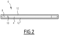
Figure 2 is a cross-sectional view of the nuclear fuel element along II - II onFigure 1 ; -
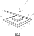
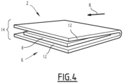
Figures 3 and4 illustrate sealing of the core of the nuclear fuel element shown inFigures 1 and2 into a cladding; -
Figure 5 and6 illustrate cross-sectional views of nuclear fuel elements taken with an optical microscope. - The
nuclear fuel element 2 illustrated onFigure 1 is for example intended to be used as a primary target in a nuclear reactor or as a nuclear fuel for a research nuclear reactor in order to obtain neutrons. - The
nuclear fuel element 2 is plate-shaped. The nuclear fuel element has for example a length of approx. 150 mm for a primary target and up to approx. 1000 mm for a nuclear fuel for research reactor, a width of e.g. 40 to 90 mm, and a thickness of approx. 1 to 3 mm. In view of obtaining a cylindrical nuclear fuel product, the plate-shaped fuel element 2 is e.g. rolled and welded on a diameter usually about 20 to 50 mm, e.g. 30 mm. - As visible on
Figure 2 , thenuclear fuel element 2 comprises acore 4 made of a fissile material, thecore 4 being sealed in acladding 6. - The
core 4 is surrounded by the cladding 6 in a sealed manner. Thecladding 6 prevents the fissile material of thecore 4 from migrating outside thecladding 6. Thecladding 6 also holds the fissile products generated during irradiation of thenuclear fuel element 2. - The fissile material comprises for example uranium. The uranium content of the fissile material is preferably equal or higher than 2.5 gU/cm3, preferably strictly higher than 4.8 gU/cm3. The uranium content of the core material is for example equal or less than 6.5 gU/cm3, in particular equal or less than 5.3 gU/cm3.
- The uranium contained in the fissile material is for example Low Enriched Uranium (LEU). By LEU, it is meant that the proportion of isotope U235 in the uranium is below 20 wt%, for example around 19.75 wt%.
- The fissile material contains for example an uranium alloy, in particular an uranium alloy chosen among the group consisting of uranium-silicon alloy, uranium-molybdenum alloy, uranium-aluminium alloy and uranium-zirconium alloy, or a mixture thereof.
- In a specific embodiment, the fissile material contains one single uranium alloy, in particular an uranium alloy chosen among the group consisting of uranium-silicon alloy, uranium-molybdenum alloy, uranium-aluminium alloy and uranium-zirconium alloy,
- In a preferred embodiment, the uranium contained in the fissile material of the
core 4 is provided as U3Si2. - The
cladding 6 comprises aframe 8 having anaperture 10 receiving thecore 4 and a twocover plates 12 placed on the opposed faces of theframe 8 such that theframe 8 and thecore 4 received in thecentral aperture 10 are sandwiched between thecover plates 12. - The
frame 8 is made in a first cladding material and thecover plates 12 are made of a second cladding material different from the first cladding material. - The first cladding material has a hardness that is strictly higher than the hardness of the second cladding material and, preferably, strictly lower than the hardness of the core 4 (i.e. the hardness of the fissile material).
- As it will be explained below, a method for manufacturing the
nuclear fuel element 2 may comprise a hot-rolling performed at a temperature comprised for example between 300°C and 600°C, in particular between 350°C and 450°C. - In the temperature range comprised between 300°C and 600°C, in particular in the temperature range comprised temperature 350°C and 450°C, the first cladding material has for example a Vickers hardness (HV) comprised between 40 and 70 HV, the second cladding material has for example a Vickers hardness comprised between 30 and 60 HV and/or the
core 4 has for example a Vickers hardness comprised between 50 and 100 HV. - As it will be explained below, a method for manufacturing the
nuclear fuel element 2 may comprise a cold-rolling performed at room temperature. - At room temperature, the first cladding material has for example a Vickers hardness (HV) comprised between 50 and 100 HV, the second cladding material has for example a Vickers hardness comprised between 30 and 70 HV and/or the
core 4 has for example a Vickers hardness equal to or greater than 100 HV. - The first cladding material and the second cladding material are for example metallic materials.
- Each of the first cladding material and the second cladding material may be any type of metallic materials generally used in nuclear reactors, i.e. an aluminium alloy, such as EN AW-1050A, EN AW-6061, EN AW-5754, EN AW-5083, EN AW-5019 or AlFeNi, a zirconium alloy such as Zircaloy-2, Zircaloy-4 or Zr-Nb alloy, a Ni-based alloy such as Alloy 600, or stainless steel such as AISI 304L or AISI 316L.
- The first cladding material is for example an aluminium-magnesium alloy (AI-Mg) in particular EN AW-5083, also known as AG4, or EN AW-5019, also known as AG5.
- The second cladding material is for example an aluminium-magnesium alloy, in particular EN AW-5754, also known as AG3, comprising for example about 3 wt% of magnesium.
- As illustrated on
Figures 3 and4 , a method of manufacturing thenuclear fuel element 2 comprises the steps of: - providing the
core 4, theframe 8 and thecover plates 12, - inserting the
core 4 into theaperture 10 of theframe 8, - placing the
cover plates 12 to sandwich theframe 8 containing thecore 4 with the cover plates 12 (seeFigure 4 ), and - rolling the sandwich formed by the
core 4 and theframe 8 received between thecover plates 12 such that thecover plates 12 are bonded to theframe 8, thecore 4 being sealed into thecladding 6 defined by theframe 8 and the cover plates 12 (see arrow R onFigure 4 ). - In a first substep, uranium and each other component of the uranium alloy of the fissile material are melted in a furnace, for example an arc furnace, an induction furnace or a resistance furnace. If any, the above-mentioned additional element(s) may be added to the melt in this first substep.
- In a second substep, the melt is poured into a mould in order to form an ingot.
- In a third substep, the ingot is grinded in order to obtain a uranium alloy powder. Advantageously the average size of the powder particles is less than 100µm, for example between 40 µm and 70 µm. For determining the powder particle size, laser granulometry can advantageously be used, in accordance with standard NF ISO 13320.
- In a fourth substep, the powder is compacted to obtain a compact, for example having the shape of a parallelepiped. Advantageously, the compact has approximately the final width of the
core 4 in thenuclear fuel product 1. - The porosity of the compact is advantageously determined by weighing the compact in air, then in water. During the latter measurement, the compact is completely immersed in water, with no air bubbles present on the suspension mechanism or on the compact. The porosity can then be calculated, knowing the theoretical density of the fissile material.
- As an alternative, to shorten treatment duration and/or reduce the quantity of residual porosities, the sintering substep can be performed under high pressure, advantageously between 200 and 1000 bars, and at a temperature comprised between 400°C and 900°C.
- As an alternative to the fourth and fifth substeps, the powder may be cold-sprayed on a surface, preferably a surface of the
cladding 6, advantageously at a temperature comprised between 300 and 500°C. Cold-spraying results in a dense and high quality deposit. - As an alternative to the second to fifth substeps, the powder may be directly cast in a mold having directly the size of the core 3, the additional elements, if any, being added in the first substep.
- In view of sealing the
core 4 with acladding 6, thecore 4 is placed in thecentral aperture 10 in aframe 8. Theaperture 10 has a contour matching that of thecore 4. Thecore 4 has for example a rectangular contour. Theframe 8 extends along the sides of thecore 4. - The
frame 8 is preferably made integrally in one continuous single piece of material, e.g. by punching a plate to obtain theaperture 10. Alternatively, theframe 8 may comprise several frame pieces arranged around thecore 4 to define aframe 8 extending along the sides of thecore 4. - After placing the
core 4 inside theframe 8, thecover plates 12 are placed on the opposed faces of theframe 8, in order to form asandwich 14 comprising theframe 8 receiving thecore 4 sandwiched between the twocover plates 12. - The two
cover plates 12 are for example obtained by folding a sheet as shown onFigures 3 and4 . In such case, the twocover plates 12 are made integrally in one continuous single piece of material. Alternatively, the twocover plates 12 are provided separately. - In
Figure 4 , thecladding 6 is sealed by rolling thesandwich 14 such that thecover plates 12 are bonded to theframe 8. Eachcover plate 12 is thus bonded at its periphery to theframe 8 with closing theframe 8 in a sealed manner. - The rolling is for example a hot-rolling. The hot-rolling is preferably performed at a temperature comprised between 300°C and 600°C, in particular a temperature comprised between 350 and 450°C.
- The rolling is preferably performed along one rolling direction R, with one or several passe(s) along this rolling direction R.
- The rolling step brings the
core 4 to its final thickness and size and ensures a proper sealing of thecore 4 inside thecladding 6 formed by theframe 8 and the upper andlower plates 12. - Optionally, the rolling step includes cold-rolling of the
nuclear fuel element 2 performed after hot-rolling. Cold-rolling is performed at a temperature that is strictly lower than the temperature during hot-rolling. Cold-rolling is performed preferably at room temperature. Cold-rolling is performed e.g. to adjust the thickness and the length of thecore 4. - Optionally, the final planar dimensions of the
nuclear fuel element 2 are adjusted by cutting the edges of thenuclear fuel element 2. The cutting by any cutting technique such as press cutting, water cutting, laser cutting... - Optionally, the final thickness of the
nuclear fuel element 2 is adjusted for example by machining, chemical etching... - Optionally, the
nuclear fuel element 2 is submitted to a chemical cleaning according to known processes. Chemial cleaning is performed e.g. to degrease the nuclear fuel element. - Upon rolling the
sandwich 14 in the rolling direction R, waves tends to form in thecore 4 and to propagate towards the edges of thecore 4 along the corresponding sides of theframe 8. - The apparition of a wave increases the risk of occurrence of a "dog-bone" effect with at least one of the cladding covers 12 being too thin in register with the wave, whereby the
nuclear fuel element 2 has to be rebutted. - The size of the wave formed in the fissile material of the
core 4 during rolling increases when the flow rate of the fissile material decreases and the flow rate of the fissile material decreases when the density of the fissile material increase. - Therefore, increasing the uranium content of the
core 4 by increasing the density of thecore 4 tends to increase the risk of occurrence of a detrimental dog-bone effect. - However, as the first cladding material of the
frame 8 has a hardness that is strictly greater than the hardness of the second cladding material of thecover plates 12, theframe 8 is more resistant to deformation than thecover plates 12 and therefore tends to limit the size of a wave that is formed in thecore 4 during rolling. - Besides, the first cladding material of the
frame 8 having a hardness that is strictly lower than the hardness of thecore 4 is less resistant to deformation than thecore 4 which limits the risk or formation of a wave that is formed in thecore 4 during rolling. - Hence, the
frame 8 made of a first cladding material harder than that of thecover plates 12 and less hard than thecore 4 allows increasing the uranium contend of thecore 4 by increasing density of thecore 4 with limiting the risk of occurrence of a detrimental dog-bone effect. - The properties of the
nuclear fuel element 2 are important, in particular for use as a primary target in a nuclear reactor or as a nuclear fuel for a research nuclear reactor in order to obtain neutrons. - The geometry and composition of the
core 4, including the fissile material and the density of thecore 4, are important for neutronics. The cladding material is important for the chemistry of the primary circuit of the nuclear reactor. - The increase in uranium content of the
core 4 with limitation of the risk of occurrence of a dog-bone effect can be obtained with materials (fissile material, first cladding material and second cladding material), shapes, dimensions and manufacturing techniques that are already qualified for uses in nuclear reactors. - Grinding the ingot into powder and then sintering the compact made from the powder provides a good homogeneity of the
core 4 and allows reducing its porosity to a desired level, and therefore increasing its density and its uranium content. - Direct casting of the
core 4 leads to anon-porous core 4. -
Figure 5 illustrates a view taken with an optical microscope of a cross-section of a firstnuclear fuel element 2A having acore 4A made of U3Si2 and in which theframe 8A and thecover plates 12A are made of the same material that is AG3 whereby theframe 8A and thecover plates 12A have the same hardness. -
Figure 6 a view taken with an optical microscope of a cross-section of a secondnuclear fuel element 2B that differs from that ofFigure 5 only in that theframe 8B is made of AG5 that is harder than thecover plates 12B made of AG3. - The first
nuclear fuel element 2A and the secondnuclear fuel element 2B were both manufactured with the same manufacturing method operated under the same conditions and including rolling a sandwich formed of a core inserted in a frame sandwiched between two cover plates. -
Figure 5 and6 illustrate that the dog-bone effect appears on the firstnuclear fuel element 2A in which theframe 8A and thecover plates 12A are made of the same material and is limited or even avoided in the secondnuclear fuel element 2B in which theframe 8A and thecover plates 12A are made of different materials, the material of theframe 8B being harder than the material of thecover plates 12A. - In particular, a first minimal thickness TA of the
covers plates 12A of the firstnuclear fuel element 2A is strictly lower than a second minimal thickness TB of thecovers plates 12B of the secondnuclear fuel element 2B. - In the present case, the first minimal thickness was measured at 204 µm and the second minimal thickness was measured at 386 µm.
Claims (14)
- Plate-shaped nuclear fuel element (2) comprising a core (4) made of a fissile material and a cladding (6), the cladding comprising a frame (8) defining a central aperture (10) receiving the core (4) and two cover plates (12) sandwiching the frame (8) and the core (4), wherein the frame (8) is made of a metallic first cladding material and the cover plates (12) are made of a metallic second cladding material, the first cladding material having a hardness strictly greater than the hardness of the second cladding material.
- Nuclear fuel element according to claim 1, wherein said hardness of the first cladding material is strictly lower than that of the core (4).
- Nuclear fuel element according to claim 1 or 2, wherein the first cladding material is an aluminum alloy or a zirconium alloy.
- Nuclear fuel element according to any one of the preceding claims, wherein the first cladding material is an aluminum-magnesium alloy.
- Nuclear fuel element according to any one of the preceding claims, wherein the first cladding material is an AG4 or AG5 aluminum-magnesium alloy.
- Nuclear fuel element according to any one of the preceding claims, wherein the second cladding material is an aluminum alloy or a zirconium alloy.
- Nuclear fuel element according to any one of the preceding claims, wherein the second cladding material is an aluminum-magnesium alloy.
- Nuclear fuel element according to any one of the preceding claims, wherein the second cladding material is an AG3 aluminum-magnesium alloy.
- Nuclear fuel element according to any one of the preceding claims, wherein the fissile material contains at least one uranium alloy.
- Nuclear fuel element according to any one of the preceding claims, wherein the fissile material contains an uranium-silicon alloy, an uranium-molybdenum alloy, an uranium-aluminum alloy, an uranium-zirconium alloy or a combination thereof
- Nuclear fuel element according to any one of the preceding claims, wherein the fissile material is made of U3Si2.
- Nuclear fuel element according to any one of the preceding claims, wherein a content of uranium of the fissile material is equal to or more than 2.5 gU/cm3, in particular strictly more than 4.8 gU/cm3.
- Nuclear fuel element according to any one of the preceding claims, wherein a content of uranium of the fissile material is less than 6.5 gU/cm3, in particular less than 5.3 gU/cm3.
- Method of manufacturing a plate-shaped nuclear fuel element according to any one of the preceding claims, the method comprising:- providing the core (4), the frame (8) having the aperture (10) and the cover plates (12),- inserting the core (4) into the aperture (10) of the frame (8),- covering the frame (10) containing the core (4) with the two cover plates (12) such that the cover plates (12) sandwich the frame (8) and the core (4),- rolling the sandwich such that the cover plates (12) are bonded to the frame (8), the core (4) being sealed into the cladding (6) defined by the frame (8) and the cover plates (12).
Priority Applications (10)
| Application Number | Priority Date | Filing Date | Title |
|---|---|---|---|
| EP21306462.9A EP4170681A1 (en) | 2021-10-19 | 2021-10-19 | Plate-shaped nuclear fuel element and method of manufacturing the same |
| CN202280070540.XA CN118120031A (en) | 2021-10-19 | 2022-10-17 | Plate-shaped nuclear fuel element and method for manufacturing the same |
| PCT/EP2022/078819 WO2023066859A1 (en) | 2021-10-19 | 2022-10-17 | Plate-shaped nuclear fuel element and method of manufacturing the same |
| JP2024523386A JP2024538193A (en) | 2021-10-19 | 2022-10-17 | Plate-shaped nuclear fuel element and its manufacturing method |
| AU2022372315A AU2022372315A1 (en) | 2021-10-19 | 2022-10-17 | Plate-shaped nuclear fuel element and method of manufacturing the same |
| KR1020247012640A KR20240088893A (en) | 2021-10-19 | 2022-10-17 | Plate-shaped nuclear fuel element and method of manufacturing the same |
| CA3234414A CA3234414A1 (en) | 2021-10-19 | 2022-10-17 | Plate-shaped nuclear fuel element and method of manufacturing the same |
| US18/700,269 US20240404714A1 (en) | 2021-10-19 | 2022-10-17 | Plate-shaped nuclear fuel element and method of manufacturing the same |
| ZA2024/02662A ZA202402662B (en) | 2021-10-19 | 2024-04-05 | Plate-shaped nuclear fuel element and method of manufacturing the same |
| JOJO/P/2024/0088A JOP20240088A1 (en) | 2021-10-19 | 2024-04-15 | Nuclear fuel element in plate form and its manufacturing method |
Applications Claiming Priority (1)
| Application Number | Priority Date | Filing Date | Title |
|---|---|---|---|
| EP21306462.9A EP4170681A1 (en) | 2021-10-19 | 2021-10-19 | Plate-shaped nuclear fuel element and method of manufacturing the same |
Publications (1)
| Publication Number | Publication Date |
|---|---|
| EP4170681A1 true EP4170681A1 (en) | 2023-04-26 |
Family
ID=78821574
Family Applications (1)
| Application Number | Title | Priority Date | Filing Date |
|---|---|---|---|
| EP21306462.9A Pending EP4170681A1 (en) | 2021-10-19 | 2021-10-19 | Plate-shaped nuclear fuel element and method of manufacturing the same |
Country Status (10)
| Country | Link |
|---|---|
| US (1) | US20240404714A1 (en) |
| EP (1) | EP4170681A1 (en) |
| JP (1) | JP2024538193A (en) |
| KR (1) | KR20240088893A (en) |
| CN (1) | CN118120031A (en) |
| AU (1) | AU2022372315A1 (en) |
| CA (1) | CA3234414A1 (en) |
| JO (1) | JOP20240088A1 (en) |
| WO (1) | WO2023066859A1 (en) |
| ZA (1) | ZA202402662B (en) |
Citations (3)
| Publication number | Priority date | Publication date | Assignee | Title |
|---|---|---|---|---|
| FR1210887A (en) | 1957-09-10 | 1960-03-11 | Atomic Energy Commission | Uranium-aluminum alloy containing silicon for fuel elements |
| GB1094505A (en) | 1965-02-15 | 1967-12-13 | Atomic Energy Authority Uk | Nuclear reactor fuel elements |
| US10847275B2 (en) * | 2011-10-21 | 2020-11-24 | Framatome | Method for producing nuclear fuel products by cold spraying a core comprising aluminum and low enriched uranium |
-
2021
- 2021-10-19 EP EP21306462.9A patent/EP4170681A1/en active Pending
-
2022
- 2022-10-17 JP JP2024523386A patent/JP2024538193A/en active Pending
- 2022-10-17 KR KR1020247012640A patent/KR20240088893A/en active Pending
- 2022-10-17 WO PCT/EP2022/078819 patent/WO2023066859A1/en not_active Ceased
- 2022-10-17 AU AU2022372315A patent/AU2022372315A1/en active Pending
- 2022-10-17 CN CN202280070540.XA patent/CN118120031A/en active Pending
- 2022-10-17 CA CA3234414A patent/CA3234414A1/en active Pending
- 2022-10-17 US US18/700,269 patent/US20240404714A1/en active Pending
-
2024
- 2024-04-05 ZA ZA2024/02662A patent/ZA202402662B/en unknown
- 2024-04-15 JO JOJO/P/2024/0088A patent/JOP20240088A1/en unknown
Patent Citations (3)
| Publication number | Priority date | Publication date | Assignee | Title |
|---|---|---|---|---|
| FR1210887A (en) | 1957-09-10 | 1960-03-11 | Atomic Energy Commission | Uranium-aluminum alloy containing silicon for fuel elements |
| GB1094505A (en) | 1965-02-15 | 1967-12-13 | Atomic Energy Authority Uk | Nuclear reactor fuel elements |
| US10847275B2 (en) * | 2011-10-21 | 2020-11-24 | Framatome | Method for producing nuclear fuel products by cold spraying a core comprising aluminum and low enriched uranium |
Also Published As
| Publication number | Publication date |
|---|---|
| US20240404714A1 (en) | 2024-12-05 |
| WO2023066859A1 (en) | 2023-04-27 |
| JP2024538193A (en) | 2024-10-18 |
| CA3234414A1 (en) | 2023-04-27 |
| KR20240088893A (en) | 2024-06-20 |
| ZA202402662B (en) | 2024-11-27 |
| CN118120031A (en) | 2024-05-31 |
| AU2022372315A1 (en) | 2024-04-18 |
| JOP20240088A1 (en) | 2024-04-15 |
Similar Documents
| Publication | Publication Date | Title |
|---|---|---|
| EP2769383B1 (en) | Method for producing nuclear fuel products with a high loading of low enriched uranium and corresponding nuclear fuel product | |
| US5965829A (en) | Radiation absorbing refractory composition | |
| US20240404714A1 (en) | Plate-shaped nuclear fuel element and method of manufacturing the same | |
| EP3360980B1 (en) | Iron-based composition for fuel element | |
| US11713498B2 (en) | Method of manufacturing uranium target to be soluble in basic solution and method of extracting radioactive Mo-99 using the same | |
| GB2089101A (en) | Nuclear fuel element containing low enrichment uranium and method for producing same | |
| RU2853922C2 (en) | Plate nuclear fuel element and method for its manufacture | |
| Durazzo et al. | Increasing productivity in the manufacture of UAl2–Al dispersion-plate targets for Mo-99 production | |
| Durazzo et al. | Manufacturing high-uranium-loaded dispersion fuel plates in Brazil | |
| JP6515357B2 (en) | Titanium material for hot rolling | |
| Thurber et al. | Development of Silicon-modified 48 Wt% U-Al Alloys for Aluminum Plate-type Fuel Elements | |
| EP1600985A2 (en) | Radiation shields and methods of making the same | |
| Paprocki et al. | Fabrication and irradiation of SM-2 core materials | |
| RU2575869C2 (en) | Method of producing nuclear fuel with high load of low-enriched uranium and corresponding nuclear fuel | |
| EP1494244B1 (en) | Material for nuclear fusion reactor excellent in high temperature characteristics comprising beryllium intermetallic compound | |
| US3697374A (en) | Gradient-type nuclear fuel plate | |
| EA033850B1 (en) | Method for producing dispersion-type fuel element and fuel pellets based thereon | |
| CN115491530A (en) | Gadolinium-containing stainless steel neutron absorption composite board and preparation method thereof | |
| CN118173298A (en) | Nuclear power station biological shielding door | |
| Pasqualini | Alternative processes of comminution and colamination of uranium molybdenum alloys | |
| JPH1048372A (en) | Fuel assembly, fuel channel box used therefor, and method of manufacturing the same | |
| Newton | Fabrication of highly-loaded low-enrichment uranium aluminide fuel plates | |
| Cunningham et al. | Fuel Dispersions in Aluminum-base Elements | |
| GB1094505A (en) | Nuclear reactor fuel elements | |
| Gibson | The manufacture of MTR fuel elements and Mo99 production targets at Dounreay |
Legal Events
| Date | Code | Title | Description |
|---|---|---|---|
| PUAI | Public reference made under article 153(3) epc to a published international application that has entered the european phase |
Free format text: ORIGINAL CODE: 0009012 |
|
| STAA | Information on the status of an ep patent application or granted ep patent |
Free format text: STATUS: THE APPLICATION HAS BEEN PUBLISHED |
|
| AK | Designated contracting states |
Kind code of ref document: A1 Designated state(s): AL AT BE BG CH CY CZ DE DK EE ES FI FR GB GR HR HU IE IS IT LI LT LU LV MC MK MT NL NO PL PT RO RS SE SI SK SM TR |
|
| STAA | Information on the status of an ep patent application or granted ep patent |
Free format text: STATUS: REQUEST FOR EXAMINATION WAS MADE |
|
| 17P | Request for examination filed |
Effective date: 20230614 |
|
| RBV | Designated contracting states (corrected) |
Designated state(s): AL AT BE BG CH CY CZ DE DK EE ES FI FR GB GR HR HU IE IS IT LI LT LU LV MC MK MT NL NO PL PT RO RS SE SI SK SM TR |
|
| GRAP | Despatch of communication of intention to grant a patent |
Free format text: ORIGINAL CODE: EPIDOSNIGR1 |
|
| STAA | Information on the status of an ep patent application or granted ep patent |
Free format text: STATUS: GRANT OF PATENT IS INTENDED |
|
| INTG | Intention to grant announced |
Effective date: 20260303 |