EP4170668A1 - Device and method for near real-time prediction of an irradiation map for interventional radiology - Google Patents
Device and method for near real-time prediction of an irradiation map for interventional radiology Download PDFInfo
- Publication number
- EP4170668A1 EP4170668A1 EP21306474.4A EP21306474A EP4170668A1 EP 4170668 A1 EP4170668 A1 EP 4170668A1 EP 21306474 A EP21306474 A EP 21306474A EP 4170668 A1 EP4170668 A1 EP 4170668A1
- Authority
- EP
- European Patent Office
- Prior art keywords
- neural network
- radiology
- acquisition parameters
- data
- image
- Prior art date
- Legal status (The legal status is an assumption and is not a legal conclusion. Google has not performed a legal analysis and makes no representation as to the accuracy of the status listed.)
- Granted
Links
Images


Classifications
-
- G—PHYSICS
- G16—INFORMATION AND COMMUNICATION TECHNOLOGY [ICT] SPECIALLY ADAPTED FOR SPECIFIC APPLICATION FIELDS
- G16H—HEALTHCARE INFORMATICS, i.e. INFORMATION AND COMMUNICATION TECHNOLOGY [ICT] SPECIALLY ADAPTED FOR THE HANDLING OR PROCESSING OF MEDICAL OR HEALTHCARE DATA
- G16H20/00—ICT specially adapted for therapies or health-improving plans, e.g. for handling prescriptions, for steering therapy or for monitoring patient compliance
- G16H20/40—ICT specially adapted for therapies or health-improving plans, e.g. for handling prescriptions, for steering therapy or for monitoring patient compliance relating to mechanical, radiation or invasive therapies, e.g. surgery, laser therapy, dialysis or acupuncture
-
- A—HUMAN NECESSITIES
- A61—MEDICAL OR VETERINARY SCIENCE; HYGIENE
- A61N—ELECTROTHERAPY; MAGNETOTHERAPY; RADIATION THERAPY; ULTRASOUND THERAPY
- A61N5/00—Radiation therapy
- A61N5/10—X-ray therapy; Gamma-ray therapy; Particle-irradiation therapy
- A61N5/1048—Monitoring, verifying, controlling systems and methods
- A61N5/1064—Monitoring, verifying, controlling systems and methods for adjusting radiation treatment in response to monitoring
-
- A—HUMAN NECESSITIES
- A61—MEDICAL OR VETERINARY SCIENCE; HYGIENE
- A61N—ELECTROTHERAPY; MAGNETOTHERAPY; RADIATION THERAPY; ULTRASOUND THERAPY
- A61N5/00—Radiation therapy
- A61N5/10—X-ray therapy; Gamma-ray therapy; Particle-irradiation therapy
- A61N5/103—Treatment planning systems
- A61N5/1031—Treatment planning systems using a specific method of dose optimization
-
- A—HUMAN NECESSITIES
- A61—MEDICAL OR VETERINARY SCIENCE; HYGIENE
- A61N—ELECTROTHERAPY; MAGNETOTHERAPY; RADIATION THERAPY; ULTRASOUND THERAPY
- A61N5/00—Radiation therapy
- A61N5/10—X-ray therapy; Gamma-ray therapy; Particle-irradiation therapy
- A61N5/103—Treatment planning systems
- A61N5/1039—Treatment planning systems using functional images, e.g. PET or MRI
-
- A—HUMAN NECESSITIES
- A61—MEDICAL OR VETERINARY SCIENCE; HYGIENE
- A61N—ELECTROTHERAPY; MAGNETOTHERAPY; RADIATION THERAPY; ULTRASOUND THERAPY
- A61N5/00—Radiation therapy
- A61N5/10—X-ray therapy; Gamma-ray therapy; Particle-irradiation therapy
- A61N5/103—Treatment planning systems
- A61N5/1031—Treatment planning systems using a specific method of dose optimization
- A61N2005/1034—Monte Carlo type methods; particle tracking
Definitions
- Various example embodiments relate to interventional radiology.
- Interventional radiology refers to all medical procedures performed by radiologists under radiological control, allowing the treatment or invasive diagnosis of numerous pathologies.
- the principle of interventional radiology is therefore to access a lesion located inside the body in order to carry out a diagnostic (sampling, for example) or therapeutic act (aimed at treating, repairing, closing, etc.).
- interventional radiology represents in certain cases an alternative to conventional surgical treatment, by making it possible to intervene inside the body, via the natural channels and without making surgical openings
- Interventional radiology therefore involves irradiating portions of the human body from within the body and for the duration of the procedure. It therefore poses a radiation risk to patients.
- prolonged exposure to X-rays can cause deterministic side effects (skin bonding, hair loss, cataracts, etc.) and non-deterministic side effects (cancers in particular).
- Imaging systems have been commercialised with functions for real-time measurement of metrics such as Dose Area Product (DAP). Examples of such systems are Toshiba's Dose Tracking System, GE Healthcare's DoseMap and Siemens' CAREwatch.
- DAP Dose Area Product
- Another family of proposals is based on a more complex simulation of the dose, in particular according to a Monte-Carlo method.
- the simulation can take into account different input parameters characterising the patient and the X-ray device, but it suffers from a very high computation time that makes it unsuitable for real time. It is therefore not possible to use such an approach to allow a practitioner to control the dose imposed on the patient during a procedure.
- this approach is also not workable for several reasons: it relies on ray tracing pre-processing which also makes it expensive in terms of computation time and not suitable for real-time.
- the article indicates a time of about 2 seconds for the calculation of an irradiation map.
- the accuracy of the estimation is not very good since it gives an average error of 8% with peaks of 22% and furthermore, the map focuses on the most irradiated areas, thus reducing the information provided to the practitioner.
- the method relies on a three-dimensional model of each exposed organ of the patient to proceed with the learning of the predictive model. In practice, this type of information is not widely available, which can only hinder the building of a learning set to build an effective predictive model. In fact, in the article, the learning is performed only on 3 "phantoms".
- An objective of the present invention is to provide a method and a system that at least partially alleviates the above-mentioned drawbacks.
- it aims to provide an irradiation map in real time, or quasi-real time, i.e. in a time allowing the practitioner to control the irradiation of the patient during the operation.
- the practitioner is not hindered in his operation by the time required to obtain the irradiation map. He can thus react during the operation according to the dynamically provided information.
- a method for obtaining an irradiation map of a patient during interventional radiology comprising:
- the invention comprises one or more of the following features which may be used separately or in partial combination with each other or in total combination with each other:
- the invention relates to a computer readable medium encoding a machine-executable program of instructions to perform a method as previously decribed.
- the invention relates to a system for obtaining a prediction for an irradiation map of a patient during interventional radiology, comprising at least one simulation module and a multilayer neural network module comprising a multilayer neural network, said system being adapted to:
- One of the aims of the invention lies in obtaining an irradiation map of a patient during radiology of a given patient.
- This irradiation map associates a quantity, or dose, of irradiation with points in space contained in an environment of the patient impacted by an interventional radiology. These points are more or less numerous according to a chosen sampling of the area.
- the irradiation map is based on data acquired during the operation involving interventional radiology.
- the irradiation map is obtained quickly enough to allow its production to the practitioner during the operation while remaining relevant to the data acquired.
- the irradiation taking place between the time of data acquisition and the production of the irradiation map can be considered negligible.
- the production of the irradiation map may allow the practitioner to react to the information represented by this map during the operation. This can be referred to as real-time, in the sense that a human practitioner is able to react dynamically to the irradiation map calculated from measured data.
- the generation of an irradiation map is based on a predictive model constituted by a multilayer neural network.
- multi-layer neural networks can be seen as black boxes whose internal parameters must be adjusted during a learning (or training) phase by presenting them with both input data and a desired output (or "label").
- the error between this desired output and the 'natural' output of the network enables the parameters to be adjusted slightly in order to reduce the error.
- the network learns to react correctly and provide a good output when presented with new, unlabelled input data.
- the neural network used may be a multilayer perceptron.
- Other neural network architectures may be possible.
- a convolutional neural network can be used (ConvNet or CNN).
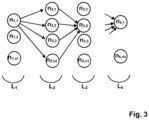
- FIG. 3 An example of a multilayer perceptron is shown in figure 3 .
- the multilayer perceptron is a type of artificial neural network organised in several layers in which information flows from the input layer L 1 to the output layer L k only; it is thus a feedforward network.
- Each layer L 1 , L 2 , L 3 ...L k consists of a variable number of neurons, respectively n 1 , n 2 , n 3 ...n k .
- the neurons of the last layer (called "output") are the outputs of the neural network and represent a prediction of the model in response to an input provided on the L 1 layer.
- each neuron n i,j is connected as an output to all the neurons of the next layer L i+1 . Conversely, it receives as input the outputs of all the neurons in the previous layer L i-1 .
- Figure 3 for clarity, only some connections are represented by oriented arrows.
- Each connection is associated with a weight.
- the set of weights form the internal parameters of the neural network. They must be determined during a learning (or training) phase and then allow the prediction of output values, by generalisation, from a new input vector presented on the L 1 input layer.
- Each neuron n i,j classically performs a weighted sum of these inputs by the weights of the associated connections and then applies an activation function to this sum.
- SGD Stochastic Gradient Descent
- arXiv:1412.6980v9 or RMSprop, described in particular in Tijmen Tieleman and Geoffrey Hinton, "Lecture 6.5-rmsprop: Divide the gradient by a running average of its recent magnitude", COURSERA: neural networks for machine learning, 4(2):26-31, 2012 .
- the process of obtaining an irradiation map includes a learning phase allowing to determine the internal parameters of the multilayer neural network.
- the multilayer neural network constitutes a predictive model that can be used in a prediction phase during an intervention (or operation).
- Figure 1 illustrates such a learning phase according to an embodiment of the invention.
- the learning phase consists of submitting the multilayer neural network 13 to a learning set comprising associations between a learning input tensor itself comprising data from a radiology image 31 of a patient's intervention area, and acquisition parameters 32 of the interventional radiology device, and labels corresponding to an irradiation map 33 obtained by simulation, by a simulation module 12, on the basis of the radiology image 31 and of these acquisition parameters 32.
- the learning set may stored in a database or data repository 20.
- this learning phase is carried out before and outside the operation involving interventional radiology.
- the learning phase is based on a set of radiology images.
- the radiology images are three-dimensional images.
- 2D images may be considered, the volume of the patient's intervention area captured by the radiology device being represented by a set of 2D images, each of them representing a layer of the volume.
- 4D images may be considered, the forth dimension being the time (video stream).
- the radiology images captures an intervention area of the patient related to the interventional radiology, i.e. locations of the patient's body where the interventional radiology is aimed to produce effects.
- radiology images may be of different kinds.
- it may be a CT scan or computerised tomography (CT).
- CT computerised tomography
- This is a medical imaging technique which consists of measuring the absorption of X-rays by tissues and then, by computer processing, digitising and finally reconstructing 2D or 3D images of anatomical structures.
- the tomographic or "slice” analysis technique is used, by subjecting the patient to the scanning of an X-ray beam.
- such a 3D image is taken prior to any intervention (or operation) in order to plan it. It is therefore possible to easily acquire a large number of such 3D images to form the training set.
- acquisition parameters 32 of the interventional radiology device to be used for the operation can be associated.
- the interventional radiology device is designed to acquire an image, generally two-dimensional, of a patient's intervention area, that is a function of these acquisition parameters.
- the interventional radiology device In practice, the interventional radiology device generates a two-dimensional image stream for the practitioner. It should be noted that these images are distinct from the one, 31, acquired before the intervention.
- the acquisition parameters are primarily the three-axis coordinates, x,y,z, of the interventional radiology device, the angles ⁇ , ⁇ of orientation of the device, and the voltage, KV, of the device's tube.
- ⁇ may represent rotation about the longitudinal axis of the patient while ⁇ may represent rotation about the horizontal axis.
- interventional radiology device Depending on the type of interventional radiology device, other parameters may be used.
- an input tensor of the neural network 13 may be formed by concatenating data from a CT scan image and acquisition parameters (x, y, z, ⁇ , ⁇ , KV), 32.
- a plurality of training set data is generated by varying the acquisition parameters (x, y, z, ⁇ , ⁇ , KV) among possible parameters.
- excursion intervals can be defined for each of the parameters x, y, z, ⁇ , ⁇ , KV as well as respective sampling rates.
- excursion intervals can be defined for the same image for which an irradiation map 33 can be simulated.
- Each three-dimensional image 31/acquisition parameters 32 pair can be produced at the input of a simulator 12 which provides a simulated irradiation map 33 at the output.
- This irradiation map 33 may be submitted as a label to the neural network 13.
- the neural network 12 is provided with:
- the neural network allows correlation between the three-dimensional image data and the acquisition parameters (x, y, z, ⁇ , ⁇ , KV), 32 with corresponding acquisition maps.
- the input tensor of the neural network contains only data produced by the interventional radiology device. No complex pre-processing needs to be performed in order to transform this acquired data into other data (apart from possible simple pre-processing such as re-scaling, re-sampling, etc. which do not change the nature of the data).
- the training set is inexpensive to build and a large number of labelled examples can be produced by simply retrieving three dimensional images.
- This training set can be further enriched by varying the acquisition parameters according to an embodiment of the invention.
- the training base is large enough to allow the neural network to converge to a stable state that minimises its cost function, so that it can train an effective predictive model.
- a training base that is too small will either give erroneous or very inaccurate predictions, or correct predictions but on examples that differ only slightly from those in the training set (reduced generalisation capacity).
- a database of CT scan images of the pancreas exists and is documented in the article H. R. Roth, L. Lu, A. Farag, H.-C. Shin, J. Liu, E. Turkbey, R. M. Summers, "Data from Pancreas-CT", 2016 .
- This database contains 82 images of 512 ⁇ 512 pixels, spaced in depth between 0.7 and 1 mm. From this database, three-dimensional images with a voxel resolution of 4 min ⁇ 4 min ⁇ 2 min can be redefined.
- a simulation module 12 may perform a simulation of the behaviour of the particles emitted by the interventional radiology device according to its acquisition parameters 32 in the patient's intervention area as defined by the three dimensional image 31.
- This simulation may be a simulation according to a Monte-Carlo method.
- the GGEMS platform for "GPU GEant4-based Monte Carlo Simulation", as described in the article by J. Bert, H. Perez-Ponce, Z. El Bitar, S. Jan, Y. Boursier, et al, "Geant4-based Monte Carlo simulations on GPU for medical applications” in Physics in Medicine and Biology, IOP Publishing, 2013, 58, pp.5593-5611 , can be used.
- the objective of GGEMS is to provide a flexible platform for the simulation of various medical applications.
- the simulation algorithm can also be modified to better fit a platform running on a GPU.
- the source constituted by the interventional radiology device can be defined as forming a conical radiation of KV value.
- the behaviour of 10 7 particles can be simulated in a time of about 6 seconds on a GPU of the NVDIA 1080 GTX Ti type.
- the acquisition parameters can be varied for each image in order to increase the population of the resulting training set.
- angles ⁇ , ⁇ vary in the ranges [-50°, 90°] and [-30°, +30°] respectively with steps of 2°.
- the position of the interventional radiology device can vary in the intervals [-30cm; +30cm] for the three parameters x, y, z, with steps of 5 cm.
- the tube voltage KV can be varied in the range [80kV, 120kV] with a step of 10kV.
- the simulation module 12 provides an irradiation map 33.
- This radiation map is a three-dimensional image that associates points in space within a simulated environment with radiation doses.
- the simulated radiation maps 33 form labels for the neural network 130 implemented by a neural network module 13.
- training involves calculating an output of the neural network 130 as a function of the input tensor to measure a cost function that estimates a distance between that output and the associated label, or irradiation map, that is desired output.
- the difference between these two values in this case two tensors, evaluated by the cost function, is used to modify the parameters of the neural network in general by a gradient descent method as previously explained.
- the cost function may be the evaluation of the mean square error between the output tensor of the neural network 13 and the desired output represented by the irradiation map (labels).
- the learning mechanism can be optimized for example by the ADAM algorithm, described in D. P. Kingma and J. Ba, “Adam: A Method for Stochastic Optimization", CoRR, abs/1412.6980 (2014 ).
- the neural network 13 may be implemented on a TensorFlow platform using the Keras API.
- the neural network is a convolutional self-encoding multilayer neural network.
- the neural network may be of the u-net type.
- the u-net neural network is a convolutional network, first described in Olaf Ronneberger, Philipp Fischer, Thomas Brox, "U-net: Convolutional networks for biomedical image segmentation", in International Conference on Medical Image Computing and Computer-Assisted Intervention, pages 234-241, Springer, 2015 .
- the neural network is based on the 3D U-net architecture.
- Figure 4 illustrates an example of such an embodiment.
- the neural network 130 of the neural network module 13 is composed of a first subnet 131 corresponding to a 3D u-net and a second subnet 132 whose output is concatenated within the first subnet.
- the first sub-network 131 itself comprises a first succession of layers constituting an encoding path (or contraction, or subsampling) and a second succession of layers constituting a decoding path (or expansion, or oversampling).
- the encoding path is a succession of convolution layers and pooling layers.
- the encoding path may comprise successions of two successive 3 ⁇ 3 ⁇ 3 convolution layers, each followed by a ReLU activation and a 2 ⁇ 2 ⁇ 2 maxPooling layer.
- the number of filters (or features) is doubled, starting with 8 for the first convolution.
- the first layer of this encoding path takes as input the tensor formed by the three-dimensional image data 31.
- the pooling operation reduces the dimensionality and captures the most relevant filters or features.
- the decoding path (right in Figure 4 ) has a succession of deconvolution and convolution layers.
- deconvolutions for example of 2 ⁇ 2 ⁇ 2 are represented by the upward arrows, while the convolutions, for example of 3 ⁇ 3 ⁇ 3 are represented by the rightward arrows in the same way as for the decoding channel.
- This neural network is related to the family of encoder-decoder networks, but unlike conventional architectures, there is a coupling between the encoding and decoding paths. More precisely, the output of each deconvolution layer is concatenated with the corresponding output in said first succession. This coupling is represented by the thin arrows in Figure 4 and the empty blocks representing the output of the deconvolution layers to be concatenated into the decoding path.
- This coupling allows the transfer of fine-grained information from the low-level layers of the encoding path to the high-level layers of the decoding path, as this information allows the generation of reconstructions with fine detail.
- the pluralities of pooling (forming a subsampling) and then oversampling operations give the network a U-shaped (functional) form which gives it its usual name of "U-net”.
- the last layers of the encoding path and the first layers of the decoding path can also be considered as forming a bottleneck.
- the neural network comprises, in an original way, a second subnetwork 132 which is coupled with the first subnetwork 131 at the level of this bottleneck.
- This second subnet 132 takes as input the acquisition parameters 32 of the interventional radiology device.
- This second sub-network may architecturally be a network of a few fully connected layers (here 3 in Figure 4 ).
- the number of filters (or "features") for the convolution and deconvolution operations have been empirically reduced by a factor of 8 compared to the original 3D u-net, in order to allow faster predictions (in the prediction phase) compatible with a real-time requirement.
- the idea of doubling the number of filters before pooling operations has however been retained.
- another distinctive feature compared to the u-net 3D scheme is the use of a padding mechanism to obtain an output of the same size as the input.
- Padding aims in avoiding the edge effect of the recurrent convolution processes applied to the images.
- pixels around the image edge can not be process due to the convolution.
- the edge around the image after processing is cropped with a size of 1 pixel. Consequently, the size of the image is reduced by two pixels on each dimension after every convolution, and it is not possible to recover this dimension on the decoder path.
- the zero-padding consists of adding pixels with zeros value around the edge of the image.
- the training can be divided into two sub-phases.
- a subset of the plurality of training set data obtained by varying the acquisition parameters among possible parameters is used. This subset is substantially smaller than this plurality.
- the module 11 generates in this sub-phase only a smaller number of parameters but preferably evenly distributed, for example using a larger step size.
- orientation angles vary in 10° steps; the x,y,z position of the source varies in 15 cm steps and the tube voltage KV varies in 40kV steps.
- This first sub-phase allows the state of the neural network to quickly converge to an acceptable state.
- the entire training set is used (i.e. with smaller steps, as previously indicated).
- the training set is specific to a particular area of intervention: for example, specific training sets may be formed for the head and neck, for the thorax, for the pelvis, etc.
- a training set may be formed for the head and neck, for the thorax, for the pelvis, etc.
- a training set can also be formed for the whole body.
- Each training set leads to a specific state of the neural network 13. This state is materialized by the values of all its parameters (synaptic weights, etc.) and thus constitutes a specific predictive model.
- these predictive models can be stored for use in the prediction phase.
- a first step may therefore be to choose the appropriate predictive model from a library of predictive models.
- This step can be manual: the practitioner chooses the intervention area, which leads to the selection of the associated predictive model.
- this step may be automatic by applying image recognition algorithms allowing automatic recognition of an area of intervention.
- This prediction phase consists in applying the predictive model for a given patient in order to predict a real-time radiation map to help or guide the practitioner during interventional radiology.
- the interventional radiology device 21 During the intervention, the interventional radiology device 21 generates an acquisition parameter stream 32. This stream is determined, for example, by a sampling rate at which it transmits the acquisition parameters to the radiation map generation system, 10 radiology.
- the parameters may be the 6-tuple previously described (x,y,z, ⁇ , ⁇ ,KV), or any set of parameters specific to the type of radiology device. In any case, these parameters must be the same as those used for the learning phase.
- the system 10 is provided to prepare an input tensor comprising data of a radiology image 31 of the given patient, e.g. a three-dimensional.
- This radiology image is of the same nature as those used in the learning phase. It may be a pre-operative image of the patient, stored in the data repository 20, or an image acquired during the interventional radiology operation. According to the invention, this image can be unique during the operation (only the parameters change over time).
- the input tensor also includes parameters for acquiring the flow generated by the interventional radiology device 21.
- Sampling may be applied to take only a sampled portion of the flow to construct this input tensor.
- the sampling may be determined based on the computation time for each prediction.
- This irradiation map 34 is of the same type as those provided as labels during the learning phase. In particular, it may provide an estimated radiation dose per unit volume of the patient's intervention area during the interventional radiology operation.
- This irradiation map can be seen as a 3D image in which each voxel is associated with an irradiation dose (instead of a colorimetric data as in a classical 3D image).
- This irradiation map can be used to assist the practitioner during his intervention on the patient.
- the patrician can view it during the procedure.
- Radiation doses can be represented by associating different colours for intervals of dose values.
- the display can be refreshed (about 15 maps per second), so that the map displayed corresponds to the present time for the patrician, allowing him/her to monitor the map in real time.
- alerts can be triggered if radiation doses exceed certain predetermined thresholds for certain sub-areas of the intervention area.
- the predicted radiation map is a 3D map.
- an estimate of the radiation dose can be obtained not only for the skin surface but also for the whole volume of the irradiated organs and body parts.
- the method uses only medical imaging data that is easy to obtain in the training phase, so that training sets can be constituted for various parts of the body that are sufficiently large to allow the neural network to converge well and thus obtain good qualitative performance in the prediction phase.
- the system 10 may be implemented by a set of circuits co-located in a centralized server or distributed within a distributed server or among a set of servers.
- This set of servers may comprise "server farm” or “cloud computing” arrangements.
- This server may also be implemented on a single computer located in the operating room.
- This system 10 may have means of communication with remote servers in order to retrieve three-dimensional images of patients, both in the learning phase and in the prediction phase (in order to obtain a pre-operative image of the patient on whom the operation is to be performed).
- the system may also have means of communication with the interventional radiology device 21 in order, in particular, to retrieve the acquisition parameters.
- These communication means may be in accordance with the technologies of the state of the art. In particular, they may be wired (Ethernet, USB, etc.) or radio (Wi-Fi, Bluetooth, 3G/4G/5G cellular, etc.) communication means.
Landscapes
- Health & Medical Sciences (AREA)
- Engineering & Computer Science (AREA)
- Biomedical Technology (AREA)
- General Health & Medical Sciences (AREA)
- Public Health (AREA)
- Nuclear Medicine, Radiotherapy & Molecular Imaging (AREA)
- Veterinary Medicine (AREA)
- Animal Behavior & Ethology (AREA)
- Pathology (AREA)
- Life Sciences & Earth Sciences (AREA)
- Radiology & Medical Imaging (AREA)
- Surgery (AREA)
- Urology & Nephrology (AREA)
- Epidemiology (AREA)
- Medical Informatics (AREA)
- Primary Health Care (AREA)
- Apparatus For Radiation Diagnosis (AREA)
Abstract
- a learning phase consisting in submitting to a neural network (130) a learning set comprising associations between a first input tensor comprising data of a first radiology image (31) of a patient's intervention area, and first acquisition parameters (32) of an interventional radiology device, and labels corresponding to an irradiation map (33) obtained by simulation (12) from the said first radiology image (31) and the said first acquisition parameters (32),
- a prediction phase on a given patient, comprising the acquisition of a stream of second acquisition parameters (32) of said interventional radiology device (21), the preparation of a second input tensor comprising data of a second radiology image (31) of said given patient and of said second acquisition parameters, the submission of said second input vector to said neural network (130) and the retrieval of an irradiation map prediction (34).
Description
- Various example embodiments relate to interventional radiology.
- It applies in particular to the prevention of risks linked to irradiation due to this type of radiology, by allowing a quasi-real time prediction of an irradiation map of the intervention environment.
- Interventional radiology refers to all medical procedures performed by radiologists under radiological control, allowing the treatment or invasive diagnosis of numerous pathologies. The principle of interventional radiology is therefore to access a lesion located inside the body in order to carry out a diagnostic (sampling, for example) or therapeutic act (aimed at treating, repairing, closing, etc.).
- Thus, in the context of therapeutic intervention, interventional radiology represents in certain cases an alternative to conventional surgical treatment, by making it possible to intervene inside the body, via the natural channels and without making surgical openings
- Different technologies can be used such as, for example, fluoroscopy, X-ray scanning, ultrasound scanning, MRI (magnetic resonance imaging), etc.
- Interventional radiology therefore involves irradiating portions of the human body from within the body and for the duration of the procedure. It therefore poses a radiation risk to patients. Thus, prolonged exposure to X-rays can cause deterministic side effects (skin bonding, hair loss, cataracts, etc.) and non-deterministic side effects (cancers in particular).
- The International Commission on Radiological Protection (ICRP) and other bodies have emphasised the importance of patient dose control during interventional radiology.
- Imaging systems have been commercialised with functions for real-time measurement of metrics such as Dose Area Product (DAP). Examples of such systems are Toshiba's Dose Tracking System, GE Healthcare's DoseMap and Siemens' CAREwatch.
- However, these systems do not take into account the specific anatomy of the patient, or even the position and orientation of the interventional radiology device. The information provided is therefore necessarily approximate. Furthermore, they estimate the dose only on the skin surface.
- Another family of proposals is based on a more complex simulation of the dose, in particular according to a Monte-Carlo method. The simulation can take into account different input parameters characterising the patient and the X-ray device, but it suffers from a very high computation time that makes it unsuitable for real time. It is therefore not possible to use such an approach to allow a practitioner to control the dose imposed on the patient during a procedure.
- It has been proposed to deploy Monte Carlo simulation methods on dedicated computing processors such as Graphics Processing Units (GPUs).
- An example of published paper is Badal A, Badano A. « Accelerating Monte Carlo simulations of photon transport in a voxelized geometry using a massively parallel graphics processing unit » in Med Phys. 2009 Nov;36(11):4878-80. doi: 10.1118/1.3231824. PMID: 19994495, or, J. Bert, H. Perez-Ponce, Z. El Bitar, S. Jan, Y. Boursier, et al.. « Geant4-based Monte Carlo simulations on GPU for medical applications » in Physics in Medicine and Biology, IOP Publishing, 2013, 58, pp.5593-5611.
- These proposals do indeed reduce calculation times, but they remain inappropriate for real time, since they are of the order of 10 seconds for the first proposal (which, moreover, does not take into account the specific anatomy of the patient) and 2 minutes for the second proposal.
- Further proposals are beginning to appear that take advantage of recent advances in the field of multilayer neural networks. These include Roser, P., Zhong, X., Birkhold, A., Strobel, N., Kowarschik, M., Fahrig, R., & Maier, A. (2019). "Physics-Driven Learning of X-ray Skin Dose Distribution in Interventional Procedures" in Medical physics, 46, 4654-4665.
- However, this approach is also not workable for several reasons: it relies on ray tracing pre-processing which also makes it expensive in terms of computation time and not suitable for real-time. The article indicates a time of about 2 seconds for the calculation of an irradiation map. Moreover, the accuracy of the estimation is not very good since it gives an average error of 8% with peaks of 22% and furthermore, the map focuses on the most irradiated areas, thus reducing the information provided to the practitioner. Also, the method relies on a three-dimensional model of each exposed organ of the patient to proceed with the learning of the predictive model. In practice, this type of information is not widely available, which can only hinder the building of a learning set to build an effective predictive model. In fact, in the article, the learning is performed only on 3 "phantoms".
- Therefore, there is no solution in the state of the art that is both near-real time and sufficiently accurate.
- An objective of the present invention is to provide a method and a system that at least partially alleviates the above-mentioned drawbacks.
- More particularly, according to embodiments, it aims to provide an irradiation map in real time, or quasi-real time, i.e. in a time allowing the practitioner to control the irradiation of the patient during the operation. In particular, the practitioner is not hindered in his operation by the time required to obtain the irradiation map. He can thus react during the operation according to the dynamically provided information.
- In a first example embodiment, a method is provided for obtaining an irradiation map of a patient during interventional radiology, comprising:
- a learning phase consisting in submitting to a multilayer neural network a learning set comprising associations between a first input tensor comprising data of a first radiology image of a patient's intervention area, and first acquisition parameters of an interventional radiology device, and labels corresponding to an irradiation map obtained by simulation by a simulation module from the said first radiology image and the said first acquisition parameters,
- a prediction phase on a given patient, comprising the acquisition of a stream of second acquisition parameters of said interventional radiology device, the preparation of a second input tensor comprising data of a second radiology image of said given patient and of said second acquisition parameters, the submission of said second input vector to said neural network and the retrieval of an irradiation map prediction.
- In preferred embodiments, the invention comprises one or more of the following features which may be used separately or in partial combination with each other or in total combination with each other:
- during the learning phase, a plurality of data of the learning set is generated for a first radiology image by varying said first acquisition parameters among possible parameters;
- said simulation is performed by a Monte-Carlo method adapted for a graphics processor:;
- said neural network is of U-Net type;
- said neural network consists of a first sub-network having as input the data of said first or second radiology image, and comprising a first succession of convolution and pooling layers and a second succession of deconvolution and convolution layers, such that the output of said neural network is of the same size as said input, and wherein the output of each deconvolution layer is concatenated with the corresponding output in said first succession; and a second sub-network having as input said first or second acquisition parameters, respectively, and whose output is concatenated with the output of the last pooling layer of said first succession;
- said input tensor is a concatenation of said data of a first radiology image and said first acquisition parameters;
- said radiology image is a computerized tomography scan.
- According to other embodiments, the invention relates to a computer readable medium encoding a machine-executable program of instructions to perform a method as previously decribed.
- According to other embodiments, the invention relates to a system for obtaining a prediction for an irradiation map of a patient during interventional radiology, comprising at least one simulation module and a multilayer neural network module comprising a multilayer neural network, said system being adapted to:
- in a learning phase, submitting to said multilayer neural network a learning set comprising associations between a first input tensor comprising data of a first radiology image of a patient's intervention area, and first acquisition parameters of an interventional radiology device, and labels corresponding to an irradiation map obtained from said simulation module on the basis of said first radiology image and said first acquisition parameters; and,
- in a prediction phase on a given patient, acquiring a stream of second acquisition parameters from said interventional radiology device, preparing a second input tensor comprising data of a second radiology image of said given patient and said second acquisition parameters, submitting said second input vector to said neural network and retrieving a prediction of irradiation map.
- Further features and advantages of the invention will become apparent from the following description of a preferred embodiment of the invention, given by way of example and with reference to the attached drawings.
- Some embodiments are now described, by way of example only, and with reference to the accompagnying drawings, in which :
-
figure 1 schematically represents an example of functional architecture for a learning phase according to an embodiment of the invention. -
figure 2 schematically illustrates an example of functional architecture for a prediction phase according to an embodiment of the invention -
figure 3 schematically illustrates a basic architecture of a classical neural network. -
figure 4 schematically illustrates an example of a multilayer neural network according to an embodiment of the invention. - One of the aims of the invention lies in obtaining an irradiation map of a patient during radiology of a given patient.
- This irradiation map associates a quantity, or dose, of irradiation with points in space contained in an environment of the patient impacted by an interventional radiology. These points are more or less numerous according to a chosen sampling of the area.
- The irradiation map is based on data acquired during the operation involving interventional radiology.
- According to the invention, the irradiation map is obtained quickly enough to allow its production to the practitioner during the operation while remaining relevant to the data acquired. In other words, the irradiation taking place between the time of data acquisition and the production of the irradiation map can be considered negligible.
- The production of the irradiation map may allow the practitioner to react to the information represented by this map during the operation. This can be referred to as real-time, in the sense that a human practitioner is able to react dynamically to the irradiation map calculated from measured data.
- According to the invention, the generation of an irradiation map is based on a predictive model constituted by a multilayer neural network.
- From a very high-level point of view, multi-layer neural networks can be seen as black boxes whose internal parameters must be adjusted during a learning (or training) phase by presenting them with both input data and a desired output (or "label"). The error between this desired output and the 'natural' output of the network enables the parameters to be adjusted slightly in order to reduce the error. By presenting a large number of such "input data / desired output" pairs, the network learns to react correctly and provide a good output when presented with new, unlabelled input data.
- According to an embodiment of the invention, the neural network used may be a multilayer perceptron. Other neural network architectures may be possible. In particular, a convolutional neural network can be used (ConvNet or CNN).
- An example of a multilayer perceptron is shown in
figure 3 . - The multilayer perceptron (MLP) is a type of artificial neural network organised in several layers in which information flows from the input layer L1 to the output layer Lk only; it is thus a feedforward network. Each layer L1, L2, L3...Lk consists of a variable number of neurons, respectively n1, n2, n3...nk. The neurons of the last layer (called "output") are the outputs of the neural network and represent a prediction of the model in response to an input provided on the L1 layer.
- In a multi-layer perceptron, each neuron ni,j is connected as an output to all the neurons of the next layer Li+1. Conversely, it receives as input the outputs of all the neurons in the previous layer Li-1. In
Figure 3 , for clarity, only some connections are represented by oriented arrows. - Each connection is associated with a weight. The set of weights form the internal parameters of the neural network. They must be determined during a learning (or training) phase and then allow the prediction of output values, by generalisation, from a new input vector presented on the L1 input layer.
- Each neuron ni,j classically performs a weighted sum of these inputs by the weights of the associated connections and then applies an activation function to this sum.
- Several techniques exist to determine the internal parameters of the network, the thresholds, by learning. One example is the Stochastic Gradient Descent (SGD) algorithm, described for example in Le Cun, Yann A., et al. "Efficient backprop. Neural networks: Tricks of the trade", Springer Berlin Heidelberg, 2012. 9-48. Another example is ADAM, originally described in Diederik P. Kingma and Jimmy Lei Ba. "Adam: A method for stochastic optimization". 2014. arXiv:1412.6980v9, or RMSprop, described in particular in Tijmen Tieleman and Geoffrey Hinton, "Lecture 6.5-rmsprop: Divide the gradient by a running average of its recent magnitude", COURSERA: neural networks for machine learning, 4(2):26-31, 2012.
- Also, the process of obtaining an irradiation map includes a learning phase allowing to determine the internal parameters of the multilayer neural network.
- Once these have been determined, the multilayer neural network constitutes a predictive model that can be used in a prediction phase during an intervention (or operation).
-
Figure 1 illustrates such a learning phase according to an embodiment of the invention. - According to the invention, the learning phase consists of submitting the multilayer
neural network 13 to a learning set comprising associations between a learning input tensor itself comprising data from aradiology image 31 of a patient's intervention area, andacquisition parameters 32 of the interventional radiology device, and labels corresponding to anirradiation map 33 obtained by simulation, by asimulation module 12, on the basis of theradiology image 31 and of theseacquisition parameters 32. The learning set may stored in a database ordata repository 20. - In a conventional manner, this learning phase is carried out before and outside the operation involving interventional radiology.
- The learning phase is based on a set of radiology images.
- According to embodiments, the radiology images are three-dimensional images.
- However, according to some other embodiments, other options may be contemplated. For instance, 2D images may be considered, the volume of the patient's intervention area captured by the radiology device being represented by a set of 2D images, each of them representing a layer of the volume.
- Also, 4D images may be considered, the forth dimension being the time (video stream).
- Experiments have shown that it is fasted to predict a 3D image once by a multilayer neural network than to predict sequentially a serie of 2D images composing a 3D image.
- In the following, the wording "three dimensional images" will be preferred, but the scope of the patent encompasses 2D and 4D images as well.
- The radiology images (e.g. three-dimensional images) captures an intervention area of the patient related to the interventional radiology, i.e. locations of the patient's body where the interventional radiology is aimed to produce effects.
- These radiology images (e.g. three-dimensional images) may be of different kinds. For example, it may be a CT scan or computerised tomography (CT). This is a medical imaging technique which consists of measuring the absorption of X-rays by tissues and then, by computer processing, digitising and finally reconstructing 2D or 3D images of anatomical structures. To acquire the data, the tomographic or "slice" analysis technique is used, by subjecting the patient to the scanning of an X-ray beam.
- Typically, such a 3D image is taken prior to any intervention (or operation) in order to plan it. It is therefore possible to easily acquire a large number of such 3D images to form the training set.
- Moreover, for each of these 3D images,
acquisition parameters 32 of the interventional radiology device to be used for the operation can be associated. The interventional radiology device is designed to acquire an image, generally two-dimensional, of a patient's intervention area, that is a function of these acquisition parameters. - In practice, the interventional radiology device generates a two-dimensional image stream for the practitioner. It should be noted that these images are distinct from the one, 31, acquired before the intervention.
- The acquisition parameters are primarily the three-axis coordinates, x,y,z, of the interventional radiology device, the angles α, β of orientation of the device, and the voltage, KV, of the device's tube. α may represent rotation about the longitudinal axis of the patient while β may represent rotation about the horizontal axis.
- Depending on the type of interventional radiology device, other parameters may be used.
- According to the invention, an input tensor of the
neural network 13 may be formed by concatenating data from a CT scan image and acquisition parameters (x, y, z, α, β, KV), 32. - According to an embodiment of the invention, for each three-
dimensional image 31, a plurality of training set data is generated by varying the acquisition parameters (x, y, z, α, β, KV) among possible parameters. - To do this, excursion intervals can be defined for each of the parameters x, y, z, α, β, KV as well as respective sampling rates. Thus, a large number of possible parameterizations can be defined for the same image for which an
irradiation map 33 can be simulated. - Each three-
dimensional image 31/acquisition parameters 32 pair can be produced at the input of asimulator 12 which provides asimulated irradiation map 33 at the output. Thisirradiation map 33 may be submitted as a label to theneural network 13. - In other words, at each iteration of the learning phase, the
neural network 12, is provided with: - an input tensor comprising a three-
dimensional image 31 andacquisition parameters 32 ; - associated with a label consisting of an
irradiation map 33 simulated on the basis of this same three-dimensional image 31 and thesesame acquisition parameters 32. - In other words, the neural network allows correlation between the three-dimensional image data and the acquisition parameters (x, y, z, α, β, KV), 32 with corresponding acquisition maps.
- According to the invention, the input tensor of the neural network contains only data produced by the interventional radiology device. No complex pre-processing needs to be performed in order to transform this acquired data into other data (apart from possible simple pre-processing such as re-scaling, re-sampling, etc. which do not change the nature of the data).
- As a result, the training set is inexpensive to build and a large number of labelled examples can be produced by simply retrieving three dimensional images. This training set can be further enriched by varying the acquisition parameters according to an embodiment of the invention.
- Unlike the method described in the Roser et al. paper mentioned above, it is neither necessary to deploy costly pre-processing that would slow down the constitution of a sufficiently large learning base, nor to obtain voxelized 3D models of each patient organ. The latter requirement is indeed detrimental to the constitution of a large learning base.
- However, it is important that the training base is large enough to allow the neural network to converge to a stable state that minimises its cost function, so that it can train an effective predictive model. A training base that is too small will either give erroneous or very inaccurate predictions, or correct predictions but on examples that differ only slightly from those in the training set (reduced generalisation capacity).
- Thus, even with the invention, it is possible to take advantage of available databases collecting patient data in order to perform this learning phase.
- For example, a database of CT scan images of the pancreas exists and is documented in the article H. R. Roth, L. Lu, A. Farag, H.-C. Shin, J. Liu, E. Turkbey, R. M. Summers, "Data from Pancreas-CT", 2016. This database contains 82 images of 512 × 512 pixels, spaced in depth between 0.7 and 1 mm. From this database, three-dimensional images with a voxel resolution of 4 min × 4 min × 2 min can be redefined.
- A
simulation module 12 may perform a simulation of the behaviour of the particles emitted by the interventional radiology device according to itsacquisition parameters 32 in the patient's intervention area as defined by the threedimensional image 31. - This simulation may be a simulation according to a Monte-Carlo method.
- In particular, it may be a simulation according to a Monte Carlo method based on a GPU. For example, the GGEMS platform, for "GPU GEant4-based Monte Carlo Simulation", as described in the article by J. Bert, H. Perez-Ponce, Z. El Bitar, S. Jan, Y. Boursier, et al, "Geant4-based Monte Carlo simulations on GPU for medical applications" in Physics in Medicine and Biology, IOP Publishing, 2013, 58, pp.5593-5611, can be used. The objective of GGEMS is to provide a flexible platform for the simulation of various medical applications. The simulation algorithm can also be modified to better fit a platform running on a GPU.
- In a concrete case of experimentation of the method of the invention, the source constituted by the interventional radiology device can be defined as forming a conical radiation of KV value. For each simulation, the behaviour of 107 particles can be simulated in a time of about 6 seconds on a GPU of the NVDIA 1080 GTX Ti type.
- According to an embodiment of the invention, the acquisition parameters can be varied for each image in order to increase the population of the resulting training set.
- Typically, the angles α, β vary in the ranges [-50°, 90°] and [-30°, +30°] respectively with steps of 2°.
- The position of the interventional radiology device can vary in the intervals [-30cm; +30cm] for the three parameters x, y, z, with steps of 5 cm.
- Finally, the tube voltage KV can be varied in the range [80kV, 120kV] with a step of 10kV.
- These values of intervals and steps have been determined by studying the technical data of interventional radiology devices and by feedback from practitioners (surgeons, radiologists, etc.).
- The
simulation module 12 provides anirradiation map 33. This radiation map is a three-dimensional image that associates points in space within a simulated environment with radiation doses. - The simulated radiation maps 33 form labels for the
neural network 130 implemented by aneural network module 13. In a manner known per se, training involves calculating an output of theneural network 130 as a function of the input tensor to measure a cost function that estimates a distance between that output and the associated label, or irradiation map, that is desired output. The difference between these two values (in this case two tensors), evaluated by the cost function, is used to modify the parameters of the neural network in general by a gradient descent method as previously explained. - According to an embodiment of the invention, the cost function may be the evaluation of the mean square error between the output tensor of the
neural network 13 and the desired output represented by the irradiation map (labels). - The learning mechanism can be optimized for example by the ADAM algorithm, described in D. P. Kingma and J. Ba, "Adam: A Method for Stochastic Optimization", CoRR, abs/1412.6980 (2014).
- The
neural network 13 may be implemented on a TensorFlow platform using the Keras API. - According to an embodiment of the invention, the neural network is a convolutional self-encoding multilayer neural network.
- More particularly, the neural network may be of the u-net type.
- The u-net neural network is a convolutional network, first described in Olaf Ronneberger, Philipp Fischer, Thomas Brox, "U-net: Convolutional networks for biomedical image segmentation", in International Conference on Medical Image Computing and Computer-Assisted Intervention, pages 234-241, Springer, 2015.
- A 3D version was then proposed in O. Cicek, A. Abdulkadir, S. S. Lienkamp, T. Brox, and O. Ronneberger, "3D U-net: learning dense volumetric segmentation from sparse annotation" in Lect. Ronneberger, "3D U-net: learning dense volumetric segmentation from sparse annotation" in Lect. Notes Computing Science, vol. 9901 LNCS, pages 424-432, 2016.
- According to an embodiment of the invention, the neural network is based on the 3D U-net architecture.
-
Figure 4 illustrates an example of such an embodiment. - In particular, the
neural network 130 of theneural network module 13 is composed of a first subnet 131 corresponding to a 3D u-net and a second subnet 132 whose output is concatenated within the first subnet. - The first sub-network 131 itself comprises a first succession of layers constituting an encoding path (or contraction, or subsampling) and a second succession of layers constituting a decoding path (or expansion, or oversampling).
- The encoding path is a succession of convolution layers and pooling layers.
- More specifically, the encoding path may comprise successions of two successive 3×3×3 convolution layers, each followed by a ReLU activation and a 2×2×2 maxPooling layer. At each subsampling (or encoding) stage, the number of filters (or features) is doubled, starting with 8 for the first convolution.
- The first layer of this encoding path takes as input the tensor formed by the three-
dimensional image data 31. - The pooling operation reduces the dimensionality and captures the most relevant filters or features.
- In
Figure 4 , the horizontal arrows to the right correspond to these convolution operations and the downward arrows correspond to maxPooling operations. - Similarly, the decoding path (right in
Figure 4 ) has a succession of deconvolution and convolution layers. - The deconvolutions (or transposed convolutions, or oversampling), for example of 2×2×2 are represented by the upward arrows, while the convolutions, for example of 3×3×3 are represented by the rightward arrows in the same way as for the decoding channel.
- In this way, an output (i.e. the irradiation map 34) of the same size as the
input 31 can be obtained. - This neural network is related to the family of encoder-decoder networks, but unlike conventional architectures, there is a coupling between the encoding and decoding paths. More precisely, the output of each deconvolution layer is concatenated with the corresponding output in said first succession. This coupling is represented by the thin arrows in
Figure 4 and the empty blocks representing the output of the deconvolution layers to be concatenated into the decoding path. - This coupling allows the transfer of fine-grained information from the low-level layers of the encoding path to the high-level layers of the decoding path, as this information allows the generation of reconstructions with fine detail.
- As illustrated in the
figure 4 , the pluralities of pooling (forming a subsampling) and then oversampling operations give the network a U-shaped (functional) form which gives it its usual name of "U-net". - The last layers of the encoding path and the first layers of the decoding path can also be considered as forming a bottleneck.
- According to this embodiment, the neural network comprises, in an original way, a second subnetwork 132 which is coupled with the first subnetwork 131 at the level of this bottleneck.
- This second subnet 132 takes as input the
acquisition parameters 32 of the interventional radiology device. - This second sub-network may architecturally be a network of a few fully connected layers (here 3 in
Figure 4 ). Theoutput tensor 133 is concatenated with the output of the last pooling layer of the encoding path. This tensor has the same number of units (19×12×15=3420) as the output tensor of this last pooling layer in order to allow their concatenation. - According to an embodiment, the number of filters (or "features") for the convolution and deconvolution operations have been empirically reduced by a factor of 8 compared to the original 3D u-net, in order to allow faster predictions (in the prediction phase) compatible with a real-time requirement. The idea of doubling the number of filters before pooling operations has however been retained.
- According to one embodiment, another distinctive feature compared to the u-net 3D scheme is the use of a padding mechanism to obtain an output of the same size as the input.
- Padding aims in avoiding the edge effect of the recurrent convolution processes applied to the images.
- More precisely, pixels around the image edge can not be process due to the convolution.
- For example, in case of a 3×3×3 convolutional filter, the edge around the image after processing is cropped with a size of 1 pixel. Consequently, the size of the image is reduced by two pixels on each dimension after every convolution, and it is not possible to recover this dimension on the decoder path.
- This may be avoided by applying zero-padding to the input image before each convolution operation. The zero-padding consists of adding pixels with zeros value around the edge of the image.
- In order to optimise the learning time, different mechanisms can be implemented.
- For example, the training can be divided into two sub-phases.
- In a first sub-phase, only a subset of the plurality of training set data obtained by varying the acquisition parameters among possible parameters is used. This subset is substantially smaller than this plurality.
- For example, the
module 11 generates in this sub-phase only a smaller number of parameters but preferably evenly distributed, for example using a larger step size. - For example, the orientation angles vary in 10° steps; the x,y,z position of the source varies in 15 cm steps and the tube voltage KV varies in 40kV steps.
- This first sub-phase allows the state of the neural network to quickly converge to an acceptable state.
- In a second sub-phase, the entire training set is used (i.e. with smaller steps, as previously indicated).
- The training set is specific to a particular area of intervention: for example, specific training sets may be formed for the head and neck, for the thorax, for the pelvis, etc. A training set may be formed for the head and neck, for the thorax, for the pelvis, etc. A training set can also be formed for the whole body.
- Each training set leads to a specific state of the
neural network 13. This state is materialized by the values of all its parameters (synaptic weights, etc.) and thus constitutes a specific predictive model. - Once constituted, these predictive models (state of the neural network 13) can be stored for use in the prediction phase.
- During a prediction phase, a first step may therefore be to choose the appropriate predictive model from a library of predictive models. This step can be manual: the practitioner chooses the intervention area, which leads to the selection of the associated predictive model. According to other embodiments, this step may be automatic by applying image recognition algorithms allowing automatic recognition of an area of intervention.
- This prediction phase consists in applying the predictive model for a given patient in order to predict a real-time radiation map to help or guide the practitioner during interventional radiology.
- This phase is illustrated in
Figure 2 . - During the intervention, the
interventional radiology device 21 generates anacquisition parameter stream 32. This stream is determined, for example, by a sampling rate at which it transmits the acquisition parameters to the radiation map generation system, 10 radiology. - The parameters may be the 6-tuple previously described (x,y,z,α,β,KV), or any set of parameters specific to the type of radiology device. In any case, these parameters must be the same as those used for the learning phase.
- These parameters evolve overtime during the intervention, depending on the actions of the patrician. Their values influence the irradiation of the patient, in particular the area of the patient for the parameters (x,y,z,α,β) and the instantaneous dose for the parameter KV.
- Furthermore, the
system 10 is provided to prepare an input tensor comprising data of aradiology image 31 of the given patient, e.g. a three-dimensional. This radiology image is of the same nature as those used in the learning phase. It may be a pre-operative image of the patient, stored in thedata repository 20, or an image acquired during the interventional radiology operation. According to the invention, this image can be unique during the operation (only the parameters change over time). - The input tensor also includes parameters for acquiring the flow generated by the
interventional radiology device 21. - Sampling may be applied to take only a sampled portion of the flow to construct this input tensor. The sampling may be determined based on the computation time for each prediction.
- Once this input tensor has been prepared and submitted as an input to the
neural network 13, a prediction of the irradiation map 34 can be retrieved as an output from theneural network 13. - This irradiation map 34 is of the same type as those provided as labels during the learning phase. In particular, it may provide an estimated radiation dose per unit volume of the patient's intervention area during the interventional radiology operation.
- This irradiation map can be seen as a 3D image in which each voxel is associated with an irradiation dose (instead of a colorimetric data as in a classical 3D image).
- Experimental measurements carried out by the inventors have made it possible to estimate that an irradiation map takes less than 70 ms, with a standard GPU graphics card.
- This irradiation map can be used to assist the practitioner during his intervention on the patient.
- In particular, it can be displayed on a screen so that the patrician can view it during the procedure.
- Radiation doses can be represented by associating different colours for intervals of dose values.
- Since the time to calculate a new map is extremely short, the display can be refreshed (about 15 maps per second), so that the map displayed corresponds to the present time for the patrician, allowing him/her to monitor the map in real time.
- Also, alerts (visual, acoustic...) can be triggered if radiation doses exceed certain predetermined thresholds for certain sub-areas of the intervention area.
- For example, it may be possible to visually highlight areas that may be problematic, either because the associated radiation dose has exceeded a threshold or because it shows too much radiation dose growth, suggesting that the threshold may be exceeded in the future.
- Contrary to some prior art proposals, the predicted radiation map is a 3D map. In other words, an estimate of the radiation dose can be obtained not only for the skin surface but also for the whole volume of the irradiated organs and body parts.
- Furthermore, the error inherent in a neural network prediction is very reasonable and less than 5% compared to a reference Monte Carlo simulation.
- Moreover, as mentioned previously, the method uses only medical imaging data that is easy to obtain in the training phase, so that training sets can be constituted for various parts of the body that are sufficiently large to allow the neural network to converge well and thus obtain good qualitative performance in the prediction phase.
- In one embodiment, the
system 10 may be implemented by a set of circuits co-located in a centralized server or distributed within a distributed server or among a set of servers. This set of servers may comprise "server farm" or "cloud computing" arrangements. This server may also be implemented on a single computer located in the operating room. - This
system 10 may have means of communication with remote servers in order to retrieve three-dimensional images of patients, both in the learning phase and in the prediction phase (in order to obtain a pre-operative image of the patient on whom the operation is to be performed). - The system may also have means of communication with the
interventional radiology device 21 in order, in particular, to retrieve the acquisition parameters. - These communication means may be in accordance with the technologies of the state of the art. In particular, they may be wired (Ethernet, USB, etc.) or radio (Wi-Fi, Bluetooth, 3G/4G/5G cellular, etc.) communication means.
- Of course, the present invention is not limited to the examples and the embodiment described and represented, but is defined by the claims. In particular, it is susceptible to numerous variants accessible to the person skilled in the art.
Claims (9)
- Method for obtaining an irradiation map of a patient during interventional radiology, comprising:- a learning phase consisting in submitting to a multilayer neural network (130) a learning set comprising associations between a first input tensor comprising data of a first radiology image (31) of a patient's intervention area, and first acquisition parameters (32) of an interventional radiology device, and labels corresponding to an irradiation map (33) obtained by simulation by a simulation module (12) from the said first radiology image (31) and the said first acquisition parameters (32),- a prediction phase on a given patient, comprising the acquisition of a stream of second acquisition parameters (32) of said interventional radiology device (21), the preparation of a second input tensor comprising data of a second radiology image (31) of said given patient and of said second acquisition parameters, the submission of said second input vector to said neural network (130) and the retrieval of an irradiation map prediction (34).
- A method according to the preceding claim, wherein, during the learning phase, a plurality of data of the learning set is generated (11) for a first radiology image (31) by varying said first acquisition parameters among possible parameters.
- The method according to any of the preceding claims, wherein said simulation is performed by a Monte-Carlo method adapted for a graphics processor.
- The method according to any of the preceding claims, wherein said neural network is of U-Net type.
- A method according to the preceding claim, wherein said neural network (130) consists of a first sub-network (131) having as input the data of said first or second radiology image, and comprising a first succession of convolution and pooling layers and a second succession of deconvolution and convolution layers, such that the output of said neural network (130) is of the same size as said input, and wherein the output of each deconvolution layer is concatenated with the corresponding output in said first succession; and a second sub-network (132) having as input said first or second acquisition parameters, respectively, and whose output is concatenated with the output of the last pooling layer of said first succession.
- A method according to any of the preceding claims, wherein said input tensor is a concatenation of said data of a first radiology image (31) and said first acquisition parameters (32).
- A method according to any of the preceding claims, wherein said radiology image (31) is a computerized tomography scan.
- A computer readable medium encoding a machine-executable program of instructions to perform a method according to any one of claims 1 to 7.
- A system (10) for obtaining a prediction for an irradiation map (34) of a patient during interventional radiology, comprising at least one simulation module (12) and a multilayer neural network module (13) comprising a multilayer neural network (130), said system being adapted to- in a learning phase, submitting to said multilayer neural network (130) a learning set comprising associations between a first input tensor comprising data of a first radiology image (31) of a patient's intervention area, and first acquisition parameters (32) of an interventional radiology device, and labels corresponding to an irradiation map (33) obtained from said simulation module (12) on the basis of said first radiology image (31) and said first acquisition parameters (32); and,- in a prediction phase on a given patient, acquiring a stream of second acquisition parameters (32) from said interventional radiology device (21), preparing a second input tensor comprising data of a second radiology image (31) of said given patient and said second acquisition parameters, submitting said second input vector to said neural network (13) and retrieving a prediction of irradiation map (34).
Priority Applications (5)
| Application Number | Priority Date | Filing Date | Title |
|---|---|---|---|
| EP21306474.4A EP4170668B8 (en) | 2021-10-22 | 2021-10-22 | Device and method for near real-time prediction of an irradiation map for interventional radiology |
| PCT/EP2022/078786 WO2023066841A1 (en) | 2021-10-22 | 2022-10-17 | Device and method for near real-time prediction of an irradiation map for interventional radiology |
| JP2024522083A JP2024541833A (en) | 2021-10-22 | 2022-10-17 | Device and method for near real-time prediction of exposure maps for interventional radiology - Patents.com |
| US18/699,818 US20240408411A1 (en) | 2021-10-22 | 2022-10-17 | Device and method for near real-time prediction of an irradiation map for interventional radiology |
| EP22202276.6A EP4170669A1 (en) | 2021-10-22 | 2022-10-18 | Device and method for near real-time prediction of a scattered radiation map in an operating room |
Applications Claiming Priority (1)
| Application Number | Priority Date | Filing Date | Title |
|---|---|---|---|
| EP21306474.4A EP4170668B8 (en) | 2021-10-22 | 2021-10-22 | Device and method for near real-time prediction of an irradiation map for interventional radiology |
Publications (3)
| Publication Number | Publication Date |
|---|---|
| EP4170668A1 true EP4170668A1 (en) | 2023-04-26 |
| EP4170668B1 EP4170668B1 (en) | 2023-10-18 |
| EP4170668B8 EP4170668B8 (en) | 2023-12-06 |
Family
ID=78592768
Family Applications (2)
| Application Number | Title | Priority Date | Filing Date |
|---|---|---|---|
| EP21306474.4A Active EP4170668B8 (en) | 2021-10-22 | 2021-10-22 | Device and method for near real-time prediction of an irradiation map for interventional radiology |
| EP22202276.6A Pending EP4170669A1 (en) | 2021-10-22 | 2022-10-18 | Device and method for near real-time prediction of a scattered radiation map in an operating room |
Family Applications After (1)
| Application Number | Title | Priority Date | Filing Date |
|---|---|---|---|
| EP22202276.6A Pending EP4170669A1 (en) | 2021-10-22 | 2022-10-18 | Device and method for near real-time prediction of a scattered radiation map in an operating room |
Country Status (4)
| Country | Link |
|---|---|
| US (1) | US20240408411A1 (en) |
| EP (2) | EP4170668B8 (en) |
| JP (1) | JP2024541833A (en) |
| WO (1) | WO2023066841A1 (en) |
Cited By (1)
| Publication number | Priority date | Publication date | Assignee | Title |
|---|---|---|---|---|
| EP4760738A1 (en) | 2024-12-16 | 2026-06-17 | PTW - Freiburg Physikalisch-Technische Werkstätten Dr. Pychlau GmbH | Methods and system for training and using a neural network for determining a dose distribution in radiotherapy |
Families Citing this family (1)
| Publication number | Priority date | Publication date | Assignee | Title |
|---|---|---|---|---|
| WO2021236175A1 (en) * | 2020-05-20 | 2021-11-25 | Google Llc | Learning illumination from diverse portraits |
Family Cites Families (6)
| Publication number | Priority date | Publication date | Assignee | Title |
|---|---|---|---|---|
| JP2016107060A (en) * | 2014-11-28 | 2016-06-20 | 株式会社東芝 | Dose distribution display apparatus and x-ray diagnostic apparatus |
| JP2019141109A (en) * | 2016-04-28 | 2019-08-29 | 株式会社日立製作所 | Tracking object recognition simulator or marker recognition simulator, moving body tracking device, and irradiation system |
| US11850445B2 (en) * | 2016-09-07 | 2023-12-26 | Elekta, Inc. | System and method for learning models of radiotherapy treatment plans to predict radiotherapy dose distributions |
| JP2021519120A (en) * | 2018-03-26 | 2021-08-10 | コーニンクレッカ フィリップス エヌ ヴェKoninklijke Philips N.V. | Decision support tool for adaptive radiation therapy in CT / LINAC console |
| JP7022268B2 (en) * | 2019-08-01 | 2022-02-18 | 恵一 中川 | X-ray cone beam CT image reconstruction method |
| CN111888665B (en) * | 2020-08-13 | 2022-09-02 | 四川大学华西医院 | Construction method of three-dimensional dose distribution prediction model based on adaptive countermeasure network |
-
2021
- 2021-10-22 EP EP21306474.4A patent/EP4170668B8/en active Active
-
2022
- 2022-10-17 US US18/699,818 patent/US20240408411A1/en active Pending
- 2022-10-17 WO PCT/EP2022/078786 patent/WO2023066841A1/en not_active Ceased
- 2022-10-17 JP JP2024522083A patent/JP2024541833A/en active Pending
- 2022-10-18 EP EP22202276.6A patent/EP4170669A1/en active Pending
Non-Patent Citations (14)
| Title |
|---|
| AURALEE EDELEN ET AL: "Machine Learning for Orders of Magnitude Speedup in Multi-Objective Optimization of Particle Accelerator Systems", ARXIV.ORG, CORNELL UNIVERSITY LIBRARY, 201 OLIN LIBRARY CORNELL UNIVERSITY ITHACA, NY 14853, 19 March 2019 (2019-03-19), XP081581226 * |
| BADAL ABADANO A: "Med Phys", vol. 36, November 2009, article "Accelerating Monte Carlo simulations of photon transport in a voxelized geometry using a massively parallel graphics processing unit", pages: 4878 - 80 |
| BOUZID DOUNIA ET AL: "Monte-Carlo dosimetry for intraoperative radiotherapy using a low energy x-ray source", ACTA ONCOLOGICA., vol. 54, no. 10, 24 March 2015 (2015-03-24), GB, pages 1788 - 1795, XP055908246, ISSN: 0284-186X, DOI: 10.3109/0284186X.2015.1016623 * |
| D. P. KINGMAJ. BA: "Adam: A Method for Stochastic Optimization", CORR, ABS/1412.6980, 2014 |
| DIEDERIK P. KINGMAJIMMY LEI BA: "Adam: A method for stochastic optimization", ARXIV:1412.6980V9, 2014 |
| H. R. ROTHL. LUA. FARAGH.-C. SHINJ. LIUE. TURKBEYR. M. SUMMERS, DATA FROM PANCREAS-CT, 2016 |
| J. BERTH. PEREZ-PONCEZ. EL BITARS. JANY. BOURSIER ET AL.: "Physics in Medicine and Biology", vol. 58, 2013, IOP PUBLISHING, article "Geant4-based Monte Carlo simulations on GPU for medical applications", pages: 5593 - 5611 |
| O. CICEKA. ABDULKADIRS. S. LIENKAMPT. BROXO. RONNEBERGER: "Lect. Notes Computing Science", vol. 9901, 2016, LNCS, article "3D U-net: learning dense volumetric segmentation from sparse annotation'' in Lect. Ronneberger, ''3D U-net: learning dense volumetric segmentation from sparse annotation", pages: 424 - 432 |
| OLAF RONNEBERGERPHILIPP FISCHERTHOMAS BROX: "International Conference on Medical Image Computing and Computer-Assisted Intervention", 2015, SPRINGER, article "U-net: Convolutional networks for biomedical image segmentation", pages: 234 - 241 |
| PENG ZHAO ET AL: "A method of rapid quantification of patient-specific organ doses for CT using deep-learning-based multi-organ segmentation and GPU-accelerated Monte Carlo dose computing", MEDICAL PHYSICS., vol. 47, no. 6, 3 April 2020 (2020-04-03), US, pages 2526 - 2536, XP055911075, ISSN: 0094-2405, Retrieved from the Internet <URL:https://onlinelibrary.wiley.com/doi/full-xml/10.1002/mp.14131> DOI: 10.1002/mp.14131 * |
| ROSER, P.ZHONG, X.BIRKHOLD, A.STROBEL, N.KOWARSCHIK, M.FAHRIG, R.MAIER, A.: "Physics-Driven Learning of X-ray Skin Dose Distribution in Interventional Procedures", MEDICAL PHYSICS, vol. 46, 2019, pages 4654 - 4665 |
| SHAN HONGMING ET AL: "Synergizing medical imaging and radiotherapy with deep learning", MACHINE LEARNING: SCIENCE AND TECHNOLOGY, vol. 1, no. 2, 23 June 2020 (2020-06-23), pages 021001, XP055881802, Retrieved from the Internet <URL:https://iopscience.iop.org/article/10.1088/2632-2153/ab869f> DOI: 10.1088/2632-2153/ab869f * |
| TANABE HIROYOSHI ET AL: "Fast EUV lithography simulation using convolutional neural network", JOURNAL OF MICRO/NANOLITHOGRAPHY, MEMS, AND MOEMS, SPIE - INTERNATIONAL SOCIETY FOR OPTICAL ENGINEERING, US, vol. 20, no. 4, 1 October 2021 (2021-10-01), pages 41202, XP060149677, ISSN: 1932-5150, [retrieved on 20210924], DOI: 10.1117/1.JMM.20.4.041202 * |
| TIJMEN TIELEMANGEOFFREY HINTON: "Lecture 6.5-rmsprop: Divide the gradient by a running average of its recent magnitude", COURSERA: NEURAL NETWORKS FOR MACHINE LEARNING, vol. 4, no. 2, 2012, pages 26 - 31 |
Cited By (1)
| Publication number | Priority date | Publication date | Assignee | Title |
|---|---|---|---|---|
| EP4760738A1 (en) | 2024-12-16 | 2026-06-17 | PTW - Freiburg Physikalisch-Technische Werkstätten Dr. Pychlau GmbH | Methods and system for training and using a neural network for determining a dose distribution in radiotherapy |
Also Published As
| Publication number | Publication date |
|---|---|
| EP4170668B1 (en) | 2023-10-18 |
| JP2024541833A (en) | 2024-11-13 |
| EP4170668B8 (en) | 2023-12-06 |
| US20240408411A1 (en) | 2024-12-12 |
| WO2023066841A1 (en) | 2023-04-27 |
| EP4170669A1 (en) | 2023-04-26 |
Similar Documents
| Publication | Publication Date | Title |
|---|---|---|
| US12254677B2 (en) | System and methods for augmenting X-ray images for training of deep neural networks | |
| US11559221B2 (en) | Multi-task progressive networks for patient modeling for medical scans | |
| EP3444777B1 (en) | Automatic change detection in medical images | |
| JP7500558B2 (en) | Deep Spectral Bolus Tracking | |
| CN110047128A (en) | The method and system of X ray CT volume and segmentation mask is rebuild from several X-ray radiogram 3D | |
| Foote et al. | Real-time 2D-3D deformable registration with deep learning and application to lung radiotherapy targeting | |
| CN109410273A (en) | According to the locating plate prediction of surface data in medical imaging | |
| CN113384287A (en) | Reduced interaction CT scan | |
| US20240321454A1 (en) | System And Method For Imaging | |
| US20240408411A1 (en) | Device and method for near real-time prediction of an irradiation map for interventional radiology | |
| US11995838B2 (en) | System and method for imaging | |
| CN112997216B (en) | Conversion system of positioning image | |
| JP7454435B2 (en) | Medical image processing device and medical image processing method | |
| Zheng et al. | Unsupervised cross-modality domain adaptation network for x-ray to CT registration | |
| Pradhan et al. | Conditional generative adversarial network model for conversion of 2 dimensional radiographs into 3 dimensional views | |
| CN114375405B (en) | Synthetic 4D computed tomography image generation | |
| Henrich et al. | Looc: Localizing organs using occupancy networks and body surface depth images | |
| EP4476742A1 (en) | Radiotherapy system and related method | |
| EP3698718B1 (en) | Heatmap and atlas | |
| Xing et al. | Relating speech production to tongue muscle compressions using tagged and high-resolution magnetic resonance imaging | |
| Herold | Using Deep Convolutional Networks to Regress a C-arm's Position from a single X-ray Image | |
| CN116848549A (en) | Detection of image structure via dimensionality reduction projection | |
| Lin | Advancing Deep Learning for 3D Medical Reconstruction from Sparse-View X-Rays | |
| Larsson | Segmentation of x-ray images using deep learning trained on synthetic data | |
| CN121511052A (en) | Using 3D positioning views and RGB-D cameras to improve simulated 4D CT positioning views for scan planning |
Legal Events
| Date | Code | Title | Description |
|---|---|---|---|
| PUAI | Public reference made under article 153(3) epc to a published international application that has entered the european phase |
Free format text: ORIGINAL CODE: 0009012 |
|
| STAA | Information on the status of an ep patent application or granted ep patent |
Free format text: STATUS: EXAMINATION IS IN PROGRESS |
|
| 17P | Request for examination filed |
Effective date: 20221006 |
|
| AK | Designated contracting states |
Kind code of ref document: A1 Designated state(s): AL AT BE BG CH CY CZ DE DK EE ES FI FR GB GR HR HU IE IS IT LI LT LU LV MC MK MT NL NO PL PT RO RS SE SI SK SM TR |
|
| GRAP | Despatch of communication of intention to grant a patent |
Free format text: ORIGINAL CODE: EPIDOSNIGR1 |
|
| STAA | Information on the status of an ep patent application or granted ep patent |
Free format text: STATUS: GRANT OF PATENT IS INTENDED |
|
| INTG | Intention to grant announced |
Effective date: 20230627 |
|
| GRAS | Grant fee paid |
Free format text: ORIGINAL CODE: EPIDOSNIGR3 |
|
| GRAA | (expected) grant |
Free format text: ORIGINAL CODE: 0009210 |
|
| STAA | Information on the status of an ep patent application or granted ep patent |
Free format text: STATUS: THE PATENT HAS BEEN GRANTED |
|
| RBV | Designated contracting states (corrected) |
Designated state(s): AL AT BE BG CH CY CZ DE DK EE ES FI FR GB GR HR HU IE IS IT LI LT LU LV MC MK MT NL NO PL PT RO RS SE SI SK SM TR |
|
| AK | Designated contracting states |
Kind code of ref document: B1 Designated state(s): AL AT BE BG CH CY CZ DE DK EE ES FI FR GB GR HR HU IE IS IT LI LT LU LV MC MK MT NL NO PL PT RO RS SE SI SK SM TR |
|
| REG | Reference to a national code |
Ref country code: GB Ref legal event code: FG4D |
|
| REG | Reference to a national code |
Ref country code: CH Ref legal event code: EP |
|
| REG | Reference to a national code |
Ref country code: IE Ref legal event code: FG4D |
|
| REG | Reference to a national code |
Ref country code: DE Ref legal event code: R096 Ref document number: 602021006015 Country of ref document: DE |
|
| REG | Reference to a national code |
Ref country code: CH Ref legal event code: PK Free format text: BERICHTIGUNG B8 |
|
| RAP4 | Party data changed (patent owner data changed or rights of a patent transferred) |
Owner name: CENTRE NATIONAL DE LA RECHERCHE SCIENTIFIQUE Owner name: UNIVERSITE DE STRASBOURG Owner name: CENTRE HOSPITALIER REGIONAL ET UNIVERSITAIRE DE BREST Owner name: UNIVERSITE DE BRETAGNE OCCIDENTALE Owner name: INSTITUT NATIONAL DE LA SANTE ET DE LA RECHERCHE MEDICALE |
|
| REG | Reference to a national code |
Ref country code: DE Ref legal event code: R081 Ref document number: 602021006015 Country of ref document: DE Owner name: UNIVERSITE DE STRASBOURG, FR Free format text: FORMER OWNERS: CENTRE HOSPITALIER REGIONAL ET UNIVERSITAIRE DE BREST, BREST, FR; CENTRE NATIONAL DE LA RECHERCHE SCIENTIFIQUE, PARIS, FR; INSTITUT NATIONAL DE LA SANTE ET DE LA RECHERCHE MEDICALE, PARIS, FR; UNIVERSITE BREST-BRETAGNE OCCIDENTALE, BREST, FR; UNIVERSITE DE STRASBOURG, STRASBOURG, FR Ref country code: DE Ref legal event code: R081 Ref document number: 602021006015 Country of ref document: DE Owner name: UNIVERSITE DE BRETAGNE OCCIDENTALE, FR Free format text: FORMER OWNERS: CENTRE HOSPITALIER REGIONAL ET UNIVERSITAIRE DE BREST, BREST, FR; CENTRE NATIONAL DE LA RECHERCHE SCIENTIFIQUE, PARIS, FR; INSTITUT NATIONAL DE LA SANTE ET DE LA RECHERCHE MEDICALE, PARIS, FR; UNIVERSITE BREST-BRETAGNE OCCIDENTALE, BREST, FR; UNIVERSITE DE STRASBOURG, STRASBOURG, FR Ref country code: DE Ref legal event code: R081 Ref document number: 602021006015 Country of ref document: DE Owner name: INSTITUT NATIONAL DE LA SANTE ET DE LA RECHERC, FR Free format text: FORMER OWNERS: CENTRE HOSPITALIER REGIONAL ET UNIVERSITAIRE DE BREST, BREST, FR; CENTRE NATIONAL DE LA RECHERCHE SCIENTIFIQUE, PARIS, FR; INSTITUT NATIONAL DE LA SANTE ET DE LA RECHERCHE MEDICALE, PARIS, FR; UNIVERSITE BREST-BRETAGNE OCCIDENTALE, BREST, FR; UNIVERSITE DE STRASBOURG, STRASBOURG, FR Ref country code: DE Ref legal event code: R081 Ref document number: 602021006015 Country of ref document: DE Owner name: CENTRE NATIONAL DE LA RECHERCHE SCIENTIFIQUE, FR Free format text: FORMER OWNERS: CENTRE HOSPITALIER REGIONAL ET UNIVERSITAIRE DE BREST, BREST, FR; CENTRE NATIONAL DE LA RECHERCHE SCIENTIFIQUE, PARIS, FR; INSTITUT NATIONAL DE LA SANTE ET DE LA RECHERCHE MEDICALE, PARIS, FR; UNIVERSITE BREST-BRETAGNE OCCIDENTALE, BREST, FR; UNIVERSITE DE STRASBOURG, STRASBOURG, FR Ref country code: DE Ref legal event code: R081 Ref document number: 602021006015 Country of ref document: DE Owner name: CENTRE HOSPITALIER REGIONAL ET UNIVERSITAIRE D, FR Free format text: FORMER OWNERS: CENTRE HOSPITALIER REGIONAL ET UNIVERSITAIRE DE BREST, BREST, FR; CENTRE NATIONAL DE LA RECHERCHE SCIENTIFIQUE, PARIS, FR; INSTITUT NATIONAL DE LA SANTE ET DE LA RECHERCHE MEDICALE, PARIS, FR; UNIVERSITE BREST-BRETAGNE OCCIDENTALE, BREST, FR; UNIVERSITE DE STRASBOURG, STRASBOURG, FR |
|
| REG | Reference to a national code |
Ref country code: NL Ref legal event code: FP |
|
| REG | Reference to a national code |
Ref country code: NL Ref legal event code: HC Owner name: UNIVERSITE DE BRETAGNE OCCIDENTALE; FR Free format text: DETAILS ASSIGNMENT: CHANGE OF OWNER(S), CHANGE OF OWNER(S) NAME; FORMER OWNER NAME: UNIVERSITE DE STRASBOURG Effective date: 20240129 |
|
| REG | Reference to a national code |
Ref country code: LT Ref legal event code: MG9D |
|
| REG | Reference to a national code |
Ref country code: AT Ref legal event code: MK05 Ref document number: 1623200 Country of ref document: AT Kind code of ref document: T Effective date: 20231018 |
|
| PG25 | Lapsed in a contracting state [announced via postgrant information from national office to epo] |
Ref country code: GR Free format text: LAPSE BECAUSE OF FAILURE TO SUBMIT A TRANSLATION OF THE DESCRIPTION OR TO PAY THE FEE WITHIN THE PRESCRIBED TIME-LIMIT Effective date: 20240119 |
|
| PG25 | Lapsed in a contracting state [announced via postgrant information from national office to epo] |
Ref country code: IS Free format text: LAPSE BECAUSE OF FAILURE TO SUBMIT A TRANSLATION OF THE DESCRIPTION OR TO PAY THE FEE WITHIN THE PRESCRIBED TIME-LIMIT Effective date: 20240218 |
|
| PG25 | Lapsed in a contracting state [announced via postgrant information from national office to epo] |
Ref country code: LT Free format text: LAPSE BECAUSE OF FAILURE TO SUBMIT A TRANSLATION OF THE DESCRIPTION OR TO PAY THE FEE WITHIN THE PRESCRIBED TIME-LIMIT Effective date: 20231018 |
|
| PG25 | Lapsed in a contracting state [announced via postgrant information from national office to epo] |
Ref country code: AT Free format text: LAPSE BECAUSE OF FAILURE TO SUBMIT A TRANSLATION OF THE DESCRIPTION OR TO PAY THE FEE WITHIN THE PRESCRIBED TIME-LIMIT Effective date: 20231018 |
|
| PG25 | Lapsed in a contracting state [announced via postgrant information from national office to epo] |
Ref country code: ES Free format text: LAPSE BECAUSE OF FAILURE TO SUBMIT A TRANSLATION OF THE DESCRIPTION OR TO PAY THE FEE WITHIN THE PRESCRIBED TIME-LIMIT Effective date: 20231018 |
|
| PG25 | Lapsed in a contracting state [announced via postgrant information from national office to epo] |
Ref country code: LT Free format text: LAPSE BECAUSE OF FAILURE TO SUBMIT A TRANSLATION OF THE DESCRIPTION OR TO PAY THE FEE WITHIN THE PRESCRIBED TIME-LIMIT Effective date: 20231018 Ref country code: IS Free format text: LAPSE BECAUSE OF FAILURE TO SUBMIT A TRANSLATION OF THE DESCRIPTION OR TO PAY THE FEE WITHIN THE PRESCRIBED TIME-LIMIT Effective date: 20240218 Ref country code: GR Free format text: LAPSE BECAUSE OF FAILURE TO SUBMIT A TRANSLATION OF THE DESCRIPTION OR TO PAY THE FEE WITHIN THE PRESCRIBED TIME-LIMIT Effective date: 20240119 Ref country code: ES Free format text: LAPSE BECAUSE OF FAILURE TO SUBMIT A TRANSLATION OF THE DESCRIPTION OR TO PAY THE FEE WITHIN THE PRESCRIBED TIME-LIMIT Effective date: 20231018 Ref country code: BG Free format text: LAPSE BECAUSE OF FAILURE TO SUBMIT A TRANSLATION OF THE DESCRIPTION OR TO PAY THE FEE WITHIN THE PRESCRIBED TIME-LIMIT Effective date: 20240118 Ref country code: AT Free format text: LAPSE BECAUSE OF FAILURE TO SUBMIT A TRANSLATION OF THE DESCRIPTION OR TO PAY THE FEE WITHIN THE PRESCRIBED TIME-LIMIT Effective date: 20231018 Ref country code: PT Free format text: LAPSE BECAUSE OF FAILURE TO SUBMIT A TRANSLATION OF THE DESCRIPTION OR TO PAY THE FEE WITHIN THE PRESCRIBED TIME-LIMIT Effective date: 20240219 |
|
| PG25 | Lapsed in a contracting state [announced via postgrant information from national office to epo] |
Ref country code: SE Free format text: LAPSE BECAUSE OF FAILURE TO SUBMIT A TRANSLATION OF THE DESCRIPTION OR TO PAY THE FEE WITHIN THE PRESCRIBED TIME-LIMIT Effective date: 20231018 Ref country code: RS Free format text: LAPSE BECAUSE OF FAILURE TO SUBMIT A TRANSLATION OF THE DESCRIPTION OR TO PAY THE FEE WITHIN THE PRESCRIBED TIME-LIMIT Effective date: 20231018 Ref country code: PL Free format text: LAPSE BECAUSE OF FAILURE TO SUBMIT A TRANSLATION OF THE DESCRIPTION OR TO PAY THE FEE WITHIN THE PRESCRIBED TIME-LIMIT Effective date: 20231018 Ref country code: NO Free format text: LAPSE BECAUSE OF FAILURE TO SUBMIT A TRANSLATION OF THE DESCRIPTION OR TO PAY THE FEE WITHIN THE PRESCRIBED TIME-LIMIT Effective date: 20240118 Ref country code: LV Free format text: LAPSE BECAUSE OF FAILURE TO SUBMIT A TRANSLATION OF THE DESCRIPTION OR TO PAY THE FEE WITHIN THE PRESCRIBED TIME-LIMIT Effective date: 20231018 Ref country code: HR Free format text: LAPSE BECAUSE OF FAILURE TO SUBMIT A TRANSLATION OF THE DESCRIPTION OR TO PAY THE FEE WITHIN THE PRESCRIBED TIME-LIMIT Effective date: 20231018 |
|
| REG | Reference to a national code |
Ref country code: BE Ref legal event code: MM Effective date: 20231031 |
|
| PG25 | Lapsed in a contracting state [announced via postgrant information from national office to epo] |
Ref country code: LU Free format text: LAPSE BECAUSE OF NON-PAYMENT OF DUE FEES Effective date: 20231022 |
|
| PG25 | Lapsed in a contracting state [announced via postgrant information from national office to epo] |
Ref country code: LU Free format text: LAPSE BECAUSE OF NON-PAYMENT OF DUE FEES Effective date: 20231022 |
|
| PG25 | Lapsed in a contracting state [announced via postgrant information from national office to epo] |
Ref country code: DK Free format text: LAPSE BECAUSE OF FAILURE TO SUBMIT A TRANSLATION OF THE DESCRIPTION OR TO PAY THE FEE WITHIN THE PRESCRIBED TIME-LIMIT Effective date: 20231018 |
|
| REG | Reference to a national code |
Ref country code: DE Ref legal event code: R097 Ref document number: 602021006015 Country of ref document: DE |
|
| PG25 | Lapsed in a contracting state [announced via postgrant information from national office to epo] |
Ref country code: CZ Free format text: LAPSE BECAUSE OF FAILURE TO SUBMIT A TRANSLATION OF THE DESCRIPTION OR TO PAY THE FEE WITHIN THE PRESCRIBED TIME-LIMIT Effective date: 20231018 |
|
| PG25 | Lapsed in a contracting state [announced via postgrant information from national office to epo] |
Ref country code: SK Free format text: LAPSE BECAUSE OF FAILURE TO SUBMIT A TRANSLATION OF THE DESCRIPTION OR TO PAY THE FEE WITHIN THE PRESCRIBED TIME-LIMIT Effective date: 20231018 |
|
| PG25 | Lapsed in a contracting state [announced via postgrant information from national office to epo] |
Ref country code: SM Free format text: LAPSE BECAUSE OF FAILURE TO SUBMIT A TRANSLATION OF THE DESCRIPTION OR TO PAY THE FEE WITHIN THE PRESCRIBED TIME-LIMIT Effective date: 20231018 Ref country code: SK Free format text: LAPSE BECAUSE OF FAILURE TO SUBMIT A TRANSLATION OF THE DESCRIPTION OR TO PAY THE FEE WITHIN THE PRESCRIBED TIME-LIMIT Effective date: 20231018 Ref country code: RO Free format text: LAPSE BECAUSE OF FAILURE TO SUBMIT A TRANSLATION OF THE DESCRIPTION OR TO PAY THE FEE WITHIN THE PRESCRIBED TIME-LIMIT Effective date: 20231018 Ref country code: IT Free format text: LAPSE BECAUSE OF FAILURE TO SUBMIT A TRANSLATION OF THE DESCRIPTION OR TO PAY THE FEE WITHIN THE PRESCRIBED TIME-LIMIT Effective date: 20231018 Ref country code: EE Free format text: LAPSE BECAUSE OF FAILURE TO SUBMIT A TRANSLATION OF THE DESCRIPTION OR TO PAY THE FEE WITHIN THE PRESCRIBED TIME-LIMIT Effective date: 20231018 Ref country code: DK Free format text: LAPSE BECAUSE OF FAILURE TO SUBMIT A TRANSLATION OF THE DESCRIPTION OR TO PAY THE FEE WITHIN THE PRESCRIBED TIME-LIMIT Effective date: 20231018 Ref country code: CZ Free format text: LAPSE BECAUSE OF FAILURE TO SUBMIT A TRANSLATION OF THE DESCRIPTION OR TO PAY THE FEE WITHIN THE PRESCRIBED TIME-LIMIT Effective date: 20231018 |
|
| PLBE | No opposition filed within time limit |
Free format text: ORIGINAL CODE: 0009261 |
|
| STAA | Information on the status of an ep patent application or granted ep patent |
Free format text: STATUS: NO OPPOSITION FILED WITHIN TIME LIMIT |
|
| PG25 | Lapsed in a contracting state [announced via postgrant information from national office to epo] |
Ref country code: MC Free format text: LAPSE BECAUSE OF FAILURE TO SUBMIT A TRANSLATION OF THE DESCRIPTION OR TO PAY THE FEE WITHIN THE PRESCRIBED TIME-LIMIT Effective date: 20231018 |
|
| PG25 | Lapsed in a contracting state [announced via postgrant information from national office to epo] |
Ref country code: MC Free format text: LAPSE BECAUSE OF FAILURE TO SUBMIT A TRANSLATION OF THE DESCRIPTION OR TO PAY THE FEE WITHIN THE PRESCRIBED TIME-LIMIT Effective date: 20231018 Ref country code: BE Free format text: LAPSE BECAUSE OF NON-PAYMENT OF DUE FEES Effective date: 20231031 |
|
| 26N | No opposition filed |
Effective date: 20240719 |
|
| PG25 | Lapsed in a contracting state [announced via postgrant information from national office to epo] |
Ref country code: IE Free format text: LAPSE BECAUSE OF NON-PAYMENT OF DUE FEES Effective date: 20231022 |
|
| PG25 | Lapsed in a contracting state [announced via postgrant information from national office to epo] |
Ref country code: SI Free format text: LAPSE BECAUSE OF FAILURE TO SUBMIT A TRANSLATION OF THE DESCRIPTION OR TO PAY THE FEE WITHIN THE PRESCRIBED TIME-LIMIT Effective date: 20231018 |
|
| PG25 | Lapsed in a contracting state [announced via postgrant information from national office to epo] |
Ref country code: SI Free format text: LAPSE BECAUSE OF FAILURE TO SUBMIT A TRANSLATION OF THE DESCRIPTION OR TO PAY THE FEE WITHIN THE PRESCRIBED TIME-LIMIT Effective date: 20231018 Ref country code: IE Free format text: LAPSE BECAUSE OF NON-PAYMENT OF DUE FEES Effective date: 20231022 |
|
| PG25 | Lapsed in a contracting state [announced via postgrant information from national office to epo] |
Ref country code: FI Free format text: LAPSE BECAUSE OF FAILURE TO SUBMIT A TRANSLATION OF THE DESCRIPTION OR TO PAY THE FEE WITHIN THE PRESCRIBED TIME-LIMIT Effective date: 20231019 |
|
| PG25 | Lapsed in a contracting state [announced via postgrant information from national office to epo] |
Ref country code: CY Free format text: LAPSE BECAUSE OF FAILURE TO SUBMIT A TRANSLATION OF THE DESCRIPTION OR TO PAY THE FEE WITHIN THE PRESCRIBED TIME-LIMIT; INVALID AB INITIO Effective date: 20211022 |
|
| REG | Reference to a national code |
Ref country code: CH Ref legal event code: U11 Free format text: ST27 STATUS EVENT CODE: U-0-0-U10-U11 (AS PROVIDED BY THE NATIONAL OFFICE) Effective date: 20251101 |
|
| PGFP | Annual fee paid to national office [announced via postgrant information from national office to epo] |
Ref country code: NL Payment date: 20251023 Year of fee payment: 5 |
|
| PG25 | Lapsed in a contracting state [announced via postgrant information from national office to epo] |
Ref country code: TR Free format text: LAPSE BECAUSE OF FAILURE TO SUBMIT A TRANSLATION OF THE DESCRIPTION OR TO PAY THE FEE WITHIN THE PRESCRIBED TIME-LIMIT Effective date: 20231018 |
|
| PGFP | Annual fee paid to national office [announced via postgrant information from national office to epo] |
Ref country code: DE Payment date: 20251020 Year of fee payment: 5 |
|
| PGFP | Annual fee paid to national office [announced via postgrant information from national office to epo] |
Ref country code: GB Payment date: 20251029 Year of fee payment: 5 |
|
| PGFP | Annual fee paid to national office [announced via postgrant information from national office to epo] |
Ref country code: FR Payment date: 20251024 Year of fee payment: 5 |
|
| PGFP | Annual fee paid to national office [announced via postgrant information from national office to epo] |
Ref country code: CH Payment date: 20251101 Year of fee payment: 5 |
|
| PG25 | Lapsed in a contracting state [announced via postgrant information from national office to epo] |
Ref country code: HU Free format text: LAPSE BECAUSE OF FAILURE TO SUBMIT A TRANSLATION OF THE DESCRIPTION OR TO PAY THE FEE WITHIN THE PRESCRIBED TIME-LIMIT; INVALID AB INITIO Effective date: 20211022 |