EP4170649A1 - Active noise cancellation system and method with time division multiplexing - Google Patents
Active noise cancellation system and method with time division multiplexing Download PDFInfo
- Publication number
- EP4170649A1 EP4170649A1 EP22202669.2A EP22202669A EP4170649A1 EP 4170649 A1 EP4170649 A1 EP 4170649A1 EP 22202669 A EP22202669 A EP 22202669A EP 4170649 A1 EP4170649 A1 EP 4170649A1
- Authority
- EP
- European Patent Office
- Prior art keywords
- information
- data
- multiplexed stream
- noise
- controller
- Prior art date
- Legal status (The legal status is an assumption and is not a legal conclusion. Google has not performed a legal analysis and makes no representation as to the accuracy of the status listed.)
- Granted
Links
Images
Classifications
-
- G—PHYSICS
- G10—MUSICAL INSTRUMENTS; ACOUSTICS
- G10K—SOUND-PRODUCING DEVICES; METHODS OR DEVICES FOR PROTECTING AGAINST, OR FOR DAMPING, NOISE OR OTHER ACOUSTIC WAVES IN GENERAL; ACOUSTICS NOT OTHERWISE PROVIDED FOR
- G10K11/00—Methods or devices for transmitting, conducting or directing sound in general; Methods or devices for protecting against, or for damping, noise or other acoustic waves in general
- G10K11/16—Methods or devices for protecting against, or for damping, noise or other acoustic waves in general
- G10K11/175—Methods or devices for protecting against, or for damping, noise or other acoustic waves in general using interference effects; Masking sound
- G10K11/178—Methods or devices for protecting against, or for damping, noise or other acoustic waves in general using interference effects; Masking sound by electro-acoustically regenerating the original acoustic waves in anti-phase
- G10K11/1785—Methods, e.g. algorithms; Devices
-
- G—PHYSICS
- G10—MUSICAL INSTRUMENTS; ACOUSTICS
- G10K—SOUND-PRODUCING DEVICES; METHODS OR DEVICES FOR PROTECTING AGAINST, OR FOR DAMPING, NOISE OR OTHER ACOUSTIC WAVES IN GENERAL; ACOUSTICS NOT OTHERWISE PROVIDED FOR
- G10K11/00—Methods or devices for transmitting, conducting or directing sound in general; Methods or devices for protecting against, or for damping, noise or other acoustic waves in general
- G10K11/16—Methods or devices for protecting against, or for damping, noise or other acoustic waves in general
- G10K11/175—Methods or devices for protecting against, or for damping, noise or other acoustic waves in general using interference effects; Masking sound
- G10K11/178—Methods or devices for protecting against, or for damping, noise or other acoustic waves in general using interference effects; Masking sound by electro-acoustically regenerating the original acoustic waves in anti-phase
- G10K11/1781—Methods or devices for protecting against, or for damping, noise or other acoustic waves in general using interference effects; Masking sound by electro-acoustically regenerating the original acoustic waves in anti-phase characterised by the analysis of input or output signals, e.g. frequency range, modes, transfer functions
- G10K11/17821—Methods or devices for protecting against, or for damping, noise or other acoustic waves in general using interference effects; Masking sound by electro-acoustically regenerating the original acoustic waves in anti-phase characterised by the analysis of input or output signals, e.g. frequency range, modes, transfer functions characterised by the analysis of the input signals only
- G10K11/17827—Desired external signals, e.g. pass-through audio such as music or speech
-
- G—PHYSICS
- G10—MUSICAL INSTRUMENTS; ACOUSTICS
- G10K—SOUND-PRODUCING DEVICES; METHODS OR DEVICES FOR PROTECTING AGAINST, OR FOR DAMPING, NOISE OR OTHER ACOUSTIC WAVES IN GENERAL; ACOUSTICS NOT OTHERWISE PROVIDED FOR
- G10K11/00—Methods or devices for transmitting, conducting or directing sound in general; Methods or devices for protecting against, or for damping, noise or other acoustic waves in general
- G10K11/16—Methods or devices for protecting against, or for damping, noise or other acoustic waves in general
- G10K11/175—Methods or devices for protecting against, or for damping, noise or other acoustic waves in general using interference effects; Masking sound
- G10K11/178—Methods or devices for protecting against, or for damping, noise or other acoustic waves in general using interference effects; Masking sound by electro-acoustically regenerating the original acoustic waves in anti-phase
- G10K11/1785—Methods, e.g. algorithms; Devices
- G10K11/17853—Methods, e.g. algorithms; Devices of the filter
- G10K11/17854—Methods, e.g. algorithms; Devices of the filter the filter being an adaptive filter
-
- G—PHYSICS
- G10—MUSICAL INSTRUMENTS; ACOUSTICS
- G10K—SOUND-PRODUCING DEVICES; METHODS OR DEVICES FOR PROTECTING AGAINST, OR FOR DAMPING, NOISE OR OTHER ACOUSTIC WAVES IN GENERAL; ACOUSTICS NOT OTHERWISE PROVIDED FOR
- G10K11/00—Methods or devices for transmitting, conducting or directing sound in general; Methods or devices for protecting against, or for damping, noise or other acoustic waves in general
- G10K11/16—Methods or devices for protecting against, or for damping, noise or other acoustic waves in general
- G10K11/175—Methods or devices for protecting against, or for damping, noise or other acoustic waves in general using interference effects; Masking sound
- G10K11/178—Methods or devices for protecting against, or for damping, noise or other acoustic waves in general using interference effects; Masking sound by electro-acoustically regenerating the original acoustic waves in anti-phase
- G10K11/1787—General system configurations
-
- G—PHYSICS
- G10—MUSICAL INSTRUMENTS; ACOUSTICS
- G10K—SOUND-PRODUCING DEVICES; METHODS OR DEVICES FOR PROTECTING AGAINST, OR FOR DAMPING, NOISE OR OTHER ACOUSTIC WAVES IN GENERAL; ACOUSTICS NOT OTHERWISE PROVIDED FOR
- G10K11/00—Methods or devices for transmitting, conducting or directing sound in general; Methods or devices for protecting against, or for damping, noise or other acoustic waves in general
- G10K11/16—Methods or devices for protecting against, or for damping, noise or other acoustic waves in general
- G10K11/175—Methods or devices for protecting against, or for damping, noise or other acoustic waves in general using interference effects; Masking sound
- G10K11/178—Methods or devices for protecting against, or for damping, noise or other acoustic waves in general using interference effects; Masking sound by electro-acoustically regenerating the original acoustic waves in anti-phase
- G10K11/1787—General system configurations
- G10K11/17879—General system configurations using both a reference signal and an error signal
-
- G—PHYSICS
- G10—MUSICAL INSTRUMENTS; ACOUSTICS
- G10K—SOUND-PRODUCING DEVICES; METHODS OR DEVICES FOR PROTECTING AGAINST, OR FOR DAMPING, NOISE OR OTHER ACOUSTIC WAVES IN GENERAL; ACOUSTICS NOT OTHERWISE PROVIDED FOR
- G10K11/00—Methods or devices for transmitting, conducting or directing sound in general; Methods or devices for protecting against, or for damping, noise or other acoustic waves in general
- G10K11/16—Methods or devices for protecting against, or for damping, noise or other acoustic waves in general
- G10K11/175—Methods or devices for protecting against, or for damping, noise or other acoustic waves in general using interference effects; Masking sound
- G10K11/178—Methods or devices for protecting against, or for damping, noise or other acoustic waves in general using interference effects; Masking sound by electro-acoustically regenerating the original acoustic waves in anti-phase
- G10K11/1787—General system configurations
- G10K11/17885—General system configurations additionally using a desired external signal, e.g. pass-through audio such as music or speech
-
- H—ELECTRICITY
- H04—ELECTRIC COMMUNICATION TECHNIQUE
- H04J—MULTIPLEX COMMUNICATION
- H04J3/00—Time-division multiplex systems
- H04J3/02—Details
- H04J3/06—Synchronising arrangements
- H04J3/0602—Systems characterised by the synchronising information used
- H04J3/0617—Systems characterised by the synchronising information used the synchronising signal being characterised by the frequency or phase
-
- H—ELECTRICITY
- H04—ELECTRIC COMMUNICATION TECHNIQUE
- H04L—TRANSMISSION OF DIGITAL INFORMATION, e.g. TELEGRAPHIC COMMUNICATION
- H04L12/00—Data switching networks
- H04L12/28—Data switching networks characterised by path configuration, e.g. LAN [Local Area Networks] or WAN [Wide Area Networks]
- H04L12/40—Bus networks
- H04L12/40006—Architecture of a communication node
- H04L12/40013—Details regarding a bus controller
-
- G—PHYSICS
- G10—MUSICAL INSTRUMENTS; ACOUSTICS
- G10K—SOUND-PRODUCING DEVICES; METHODS OR DEVICES FOR PROTECTING AGAINST, OR FOR DAMPING, NOISE OR OTHER ACOUSTIC WAVES IN GENERAL; ACOUSTICS NOT OTHERWISE PROVIDED FOR
- G10K2210/00—Details of active noise control [ANC] covered by G10K11/178 but not provided for in any of its subgroups
- G10K2210/30—Means
- G10K2210/321—Physical
- G10K2210/3214—Architectures, e.g. special constructional features or arrangements of features
-
- H—ELECTRICITY
- H04—ELECTRIC COMMUNICATION TECHNIQUE
- H04L—TRANSMISSION OF DIGITAL INFORMATION, e.g. TELEGRAPHIC COMMUNICATION
- H04L12/00—Data switching networks
- H04L12/28—Data switching networks characterised by path configuration, e.g. LAN [Local Area Networks] or WAN [Wide Area Networks]
- H04L12/40—Bus networks
- H04L2012/40267—Bus for use in transportation systems
- H04L2012/40273—Bus for use in transportation systems the transportation system being a vehicle
Definitions
- aspects disclosed herein generally relate to an active noise cancellation (ANC) system and method with time division multiplexing (TDM).
- ANC active noise cancellation
- TDM time division multiplexing
- the disclosed system and method may be implemented for ANC systems that are utilized for automotive applications.
- the disclosed system and method may also increase the capability of various sensors and other devices and preserve resources on various data communication busses or data channels.
- ANC Active noise cancellation
- a low frequency interior noise may comprise engine and road noise.
- the ANC system generally applies a multiple input multiple output (MIMO) system which includes a plurality of accelerometer sensors, a plurality of error microphones, and a plurality of loudspeakers to collect or deliver information indicative of at least the interior noise.
- MIMO multiple input multiple output
- a large amount of electrical cable or wiring may be required.
- bus systems or data buses may be utilized to reduce the amount of electrical wiring in the vehicle. However, such data busses may have inherent limitations.
- an active noise cancellation system includes a first controller, a data bus, and a second controller.
- the first controller is programmed to receive first information from a plurality of noise sensing devices and second information from an audio system positioned in a vehicle.
- the first controller is programmed to employ a time division multiplexing scheme on the first information and the second information received to generate a multiplexed stream of data including the first information and the second information.
- the data bus is configured to transmit the multiplexed stream of data on a single data channel.
- the second controller is programmed to receive the multiplexed stream of data on the single data channel and to separate the first information from the second information on the multiplexed stream of data to perform ANC functionality.
- an active noise cancellation method includes receiving first information from a plurality of noise sensing devices and second information from an audio system positioned in a vehicle and employing a time division multiplexing scheme on the first information and the second information received to generate a multiplexed stream of data including the first information and the second information.
- the method further includes transmitting the multiplexed stream of data on a single data channel of a data bus and separating the first information from the second information on the multiplexed stream of data to perform ANC functionality.
- a computer-program product embodied in a non-transitory computer read-able medium that is programmed for performing active noise cancellation in a vehicle.
- the computer-program product includes instructions for receiving first information from a plurality of noise sensing devices and second information from an audio system positioned in a vehicle and for employing a time division multiplexing scheme to the first information and the second information received to generate a multiplexed stream of data including the first information and the second information.
- the computer-program product further includes instructions for transmitting the multiplexed stream of data on a single data channel of a data bus and for separating the first information from the second information on the multiplexed stream of data to perform ANC functionality.
- controllers as disclosed herein may include various microprocessors, integrated circuits, memory devices (e.g., FLASH, random access memory (RAM), read only memory (ROM), electrically programmable read only memory (EPROM), electrically erasable programmable read only memory (EEPROM), or other suitable variants thereof), and software which co-act with one another to perform operation(s) disclosed herein.
- controllers as disclosed utilizes one or more microprocessors to execute a computer-program that is embodied in a non-transitory computer readable medium that is programmed to perform any number of the functions as disclosed.
- controller(s) as provided herein includes a housing and the various number of microprocessors, integrated circuits, and memory devices ((e.g., FLASH, random access memory (RAM), read only memory (ROM), electrically programmable read only memory (EPROM), electrically erasable programmable read only memory (EEPROM)) positioned within the housing.
- the controller(s) as disclosed also include hardware-based inputs and outputs for receiving and transmitting data, respectively from and to other hardware-based devices as discussed herein.
- Active noise cancellation (ANC) systems generally detect disturbances and undesired noise and transmit signals indicative of the undesired noise to an ANC controller.
- accelerometers mounted exterior to the vehicle may provide information indicative of road noise and error microphones positioned in an interior of the vehicle may provide information indicative of road noise or engine noise present in the interior of the vehicle.
- the ANC controller may transmit sound that is out of phase via one or more loudspeakers in the vehicle. The out of phase audio transmitted by the loudspeakers may cancel the disturbing noise present in the interior of the vehicle.
- the disclosed system and method may increase the capability of the sensors and devices in an ANC system and reduce the number of data bus channels. While reducing the number of data bus channels, the disclosed system and method may maintain high levels of ANC system performance. For example, with TDM technology, the ANC system may transmit multiple signals on one common channel. Similarly, with TMD, multiplexing and demultiplexing methods may be employed to obtain a mixed signal and restore originally transmitted multiple signals.
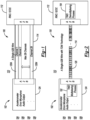
- FIGURE 1 depicts one example of a system 100 having a signal flow between various devices of an ANC system 102.
- the ANC system 102 generally includes a plurality of accelerometers 104, a plurality of error microphones 106, a plurality of loudspeakers 108, and an audio system 109.
- the audio system 109 may include an audio controller and amplifier (not shown) that is programmed to transmit one or more audio signals to the loudspeakers 108 for playback in a vehicle 110.
- the ANC system 102 may be utilized for a vehicle 110.
- the accelerometers 104 may be mounted on an external portion of the vehicle 110 and the error microphones 106 and the loudspeakers 108 may be positioned internally, within the vehicle 110.
- An ANC controller 112 is coupled to the accelerometers 104, the error microphones 106, and the loudspeakers 108.
- the digital bus 114 may enable bi-directional transfer of information between the ANC controller 112 and the accelerometers 104, the error microphones 106, and the loudspeakers 108.
- the digital bus 114 may be implemented as a single Automotive Audio Bus (A2B) to enable bi-directional data transmission between the ANC controller 112 and the accelerometers 104, the loudspeakers 106, and the loudspeakers 108.
- A2B Automotive Audio Bus
- a front-end controller 124 may be operably coupled to the accelerometers 104, the error microphones 106, and the loudspeakers 108.
- the front-end controller 124 may convert the data received from the accelerometers 104, the error microphones 106, and the loudspeakers 108 into a digital format for transmission on the A2B 114.
- the A2B 114 may be implemented as a single wire communication bus to reduce the number of wires that would otherwise be coupled between the ANC controller 112 and the accelerometers 104, the error microphones 106, and the loudspeakers 108.
- the front-end controller 124 may convert (e.g., analog to digital conversion) the data received from the accelerometers 104 the error microphones 106, and the loudspeakers 108 into a digital format for transmission on the A2B 114 to the ANC controller 112.
- the front-end controller 124 may convert (e.g., digital to analog conversion) for data that is received from the ANC controller 112 and intended for transmission to the loudspeakers 108.
- the ANC system 102 generally provides narrow band noise cancellation (e.g., engine noise cancellation) and/or broad band noise cancellation (e.g., road noise cancellation) to reduce noise in an interior cabin of the vehicle 110.
- the ANC system 112 may need a large number of different types of input sensors to satisfy ANC system performance requirements. In this case, it may be desirable to provide twenty-eight channels.
- the A2B 114 may have a constant bandwidth and a fixed number of channels 120. For example, the A2B 114 may support the twenty-eight channels with each channel 120 supporting 32 bits.
- embodiments disclosed herein provide, inter alia, for an advanced ANC system which obviates the need to add additional channels while maintaining ANC system performance.
- the embodiments disclosed herein also enable the transfer of higher bandwidth signals in one wire, such as for example, 64 bits/s or higher.
- FIGURE 2 depicts a system 150 for providing time division multiplexing (TDM) for the ANC system 102 in accordance with one embodiment.
- the front-end controller 124 may transmit data from each of the plurality of accelerometers 104, the plurality of error microphones 106, and the plurality of loudspeakers 108 (e.g., through one common channel) via a time-division multiplexing (TDM) scheme to the ANC controller 112.
- TDM time-division multiplexing
- the front-end controller 124 may include a multiplexer circuit 152 for transmitting data via the TDM scheme.
- the front-end controller 124 may transmit multiple signals into one common signal (or one mixed signal) to the ANC controller 112.
- the ANC controller 112 may include a demultiplexer circuit 154 that can demultiplex the mixed signal and restore the four channel signals.
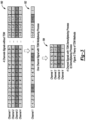
- FIGURE 3 depicts one example of a data transmission scheme employed by the system 100 and another example of the TDM scheme employed by the system 150 of FIGURE 2 both in accordance with one embodiment.
- the system 100 generally employs a plurality of channels 120 while utilizing the A2B 114. This is generally shown at 180 in FIGURE 2 .
- the system 150 generally employs a TDM scheme that utilizes a single channel 120 based on the utilization of the multiplexer circuit 152 and the demultiplexer circuit 154.
- the multiplexing aspect is generally shown at 182 and the demultiplexing aspect is generally shown at 184.
- the system 100 transmits data over, for example, 4 data channels 120a - 120d.
- the data transmitted over the channel 120a may correspond to data transmitted from a first accelerometer 104 via the front-end controller 124
- the data transmitted over the channel 120b may correspond to data transmitted from a second accelerometer 104 via the front-end controller 124
- the data transmitted over the channel 120c may correspond to data transmitted from a first error microphone 106
- the data transmitted over the channel 120d may correspond to data transmitted from the audio system 109.
- the accelerometers 104 collect the noise and/or vibration information, which has a high correlation to the interior noise.
- Each of the accelerometers 104 may output a related noise and vibration signal (which is indicative of the collected noise and vibration information) that is transferred to the front-end controller 124 as ANC system inputs.
- the front-end controller 124 transmits a digital version of the noise and vibration signals for each noise and vibration signal received to the ANC controller 112 over a corresponding data channel 120a - 120n.
- the ANC controller 112 then updates an ANC algorithm, accordingly, based on each received noise and vibration signal.
- one or more of the error microphones 106 may, for example, be positioned in a headliner and/or headrest of seats. Each error microphone 106 may output an error signal that is transmitted to the front-end controller 214.
- Each error signal generally represents noise present in the cabin of the vehicle 110 as detected by the error microphones 104.
- the front-end controller 124 transmits a digital version of the error signals for each noise and vibration signal received to the ANC controller 112 over the corresponding data channels 120a - 120n.
- the ANC controller 112 then updates an ANC algorithm, accordingly, based on each received error signal and vibration signal.
- the ANC system i.e., the ANC controller 112
- the ANC controller 112 receives the audio signal that is being played by the audio system 109 and prevents the ANC system from canceling the audio (e.g., FM signal, etc.) while the audio system 109 plays back the audio in the vehicle 110.
- the system 150 (or the front-end controller 124 via the multiplexer circuit 152) transmits data for the first accelerometer 104, the second accelerometer 104, the first error microphone 106, and the audio system 109 on a single channel 120 to the ANC controller 112.
- the data from as transmitted from each of the first accelerometer 104, the second accelerometer 104, the first error microphone 106, and the audio system 109 is divided into corresponding data packets in time slots. Thus, the data is divided over the time slots for transmission one a single channel to the ANC controller 112.
- the system 150 (or the ANC controller 112 via the demultiplexer circuit 154) aggregates or collects the data and partitions the data to coincide with dedicated channels for the data provided by the first accelerometer 104, the second accelerometer 104, the first error microphone 106, and the audio system 109.
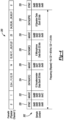
- FIGURE 4 depicts one example of a first frame of data 200 for one channel on a data bus (e.g., the A2B 114) that employs TDM and a second frame of data 202 for one channel on the data bus (e.g., the A2B 114) that employs TDM in accordance with one embodiment.
- the first frame of data 200 may include a total of 32 bits of data.
- the second frame of data 202 also includes 32 bits of data.
- the second frame of data 202 generally illustrates digital data that is generated by the front-end controller 124 for information transmitted from the accelerometer 104, the error microphone 106, and the audio system 109.
- the second frame of data 202 includes a SYNC field 220, a first MAGIC field 222, a first data field 224, a second MAGIC filed 226, a second data field 228, a third MAGIC field 230, and a third data field 232.
- the second frame of data 202 generally corresponds to an example of data transfer for a road noise cancellation (RNC) system that may include, for example, twelve accelerometers 104, eight error microphones 106, and eight loudspeakers 108.
- RNC road noise cancellation
- the SYNC field 220 is fixed as 0 x 686868 and is used to synchronize the data in one physical A2B data channel.
- Each of the first MAGIC field 222, the second MAGIC field 226, and the third MAGIC field 230 includes four bytes that include the following:
- the first MAGIC field 222 serves as an identifier that the following data corresponds to data from the accelerometers 104 (e.g., see data in the first data field 224), the second MAGIC field 226 servers as an identifier that the following data corresponds to data (e.g., see data in the second data field 228) from the error microphones 106, and the third MAGIC field 230 serves as an identifier that the following data corresponds to data from the loudspeakers 108 (e.g., see data in the second data field 232).
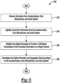
- FIGURE 5 depicts a method 250 for providing TDM for the ANC system 102 in accordance with one embodiment.
- the front-end controller 124 receives analog information from the accelerometers 104, the error microphones 106, and the loudspeakers 108.
- the front-end controller 124 converts the analog information received from the accelerometers 104, the error microphones 106, and the loudspeakers 108 into a digital format.
- the front-end controller 124 employs TDM on the digital data to provide the digital data on a single channel 120 to the ANC controller 112.
- the ANC controller 112 demultiplexes the digital data and aggregates (or collects) the information for the accelerometers 104, the error microphones 104, and the loudspeakers 108 and processes such information to perform the ANC functionality.
Landscapes
- Engineering & Computer Science (AREA)
- Physics & Mathematics (AREA)
- Acoustics & Sound (AREA)
- Multimedia (AREA)
- Computer Networks & Wireless Communication (AREA)
- Signal Processing (AREA)
- Health & Medical Sciences (AREA)
- Audiology, Speech & Language Pathology (AREA)
- General Health & Medical Sciences (AREA)
- Soundproofing, Sound Blocking, And Sound Damping (AREA)
Abstract
Description
- Aspects disclosed herein generally relate to an active noise cancellation (ANC) system and method with time division multiplexing (TDM). In one example, the disclosed system and method may be implemented for ANC systems that are utilized for automotive applications. The disclosed system and method may also increase the capability of various sensors and other devices and preserve resources on various data communication busses or data channels. These aspects and others will be discussed in more detail herein.
- Active noise cancellation (ANC) systems generally provide an effective approach to cancel low frequency interior noise in a vehicle. Such a low frequency interior noise may comprise engine and road noise. The ANC system generally applies a multiple input multiple output (MIMO) system which includes a plurality of accelerometer sensors, a plurality of error microphones, and a plurality of loudspeakers to collect or deliver information indicative of at least the interior noise. Generally, in order to couple or connect the sensors, microphones, and loudspeakers; a large amount of electrical cable or wiring may be required. Various bus systems or data buses may be utilized to reduce the amount of electrical wiring in the vehicle. However, such data busses may have inherent limitations.
- In at least one embodiment, an active noise cancellation system is disclosed. The system includes a first controller, a data bus, and a second controller. The first controller is programmed to receive first information from a plurality of noise sensing devices and second information from an audio system positioned in a vehicle. The first controller is programmed to employ a time division multiplexing scheme on the first information and the second information received to generate a multiplexed stream of data including the first information and the second information. The data bus is configured to transmit the multiplexed stream of data on a single data channel. The second controller is programmed to receive the multiplexed stream of data on the single data channel and to separate the first information from the second information on the multiplexed stream of data to perform ANC functionality.
- In at least another embodiment, an active noise cancellation method is disclosed. The method includes receiving first information from a plurality of noise sensing devices and second information from an audio system positioned in a vehicle and employing a time division multiplexing scheme on the first information and the second information received to generate a multiplexed stream of data including the first information and the second information. The method further includes transmitting the multiplexed stream of data on a single data channel of a data bus and separating the first information from the second information on the multiplexed stream of data to perform ANC functionality.
- In at least another embodiment, a computer-program product embodied in a non-transitory computer read-able medium that is programmed for performing active noise cancellation in a vehicle is disclosed. The computer-program product includes instructions for receiving first information from a plurality of noise sensing devices and second information from an audio system positioned in a vehicle and for employing a time division multiplexing scheme to the first information and the second information received to generate a multiplexed stream of data including the first information and the second information. The computer-program product further includes instructions for transmitting the multiplexed stream of data on a single data channel of a data bus and for separating the first information from the second information on the multiplexed stream of data to perform ANC functionality.
- The embodiments of the present disclosure are pointed out with particularity in the appended claims. However, other features of the various embodiments will become more apparent and will be best understood by referring to the following detailed description in conjunction with the accompany drawings in which:
-
FIGURE 1 depicts one example of a system having a signal flow between devices of an ANC system; -
FIGURE 2 depicts a system for providing time division multiplexing (TDM) for an active noise cancellation (ANC) system in accordance with one embodiment; -
FIGURE 3 depicts one example of a multiplexing scheme and a de-multiplexing scheme employed by the system ofFIGURE 2 in accordance with one embodiment; -
FIGURE 4 depicts one example of a first frame of data for one channel of on a data bus that employs TDM and also second frame of data for one channel on the data bus that employs TDM in accordance with one embodiment; and -
FIGURE 5 depicts a method for providing TDM for the ANC system in accordance with one embodiment. - As required, detailed embodiments of the present invention are disclosed herein; however, it is to be understood that the disclosed embodiments are merely exemplary of the invention that may be embodied in various and alternative forms. The figures are not necessarily to scale; some features may be exaggerated or minimized to show details of particular components. Therefore, specific structural and functional details disclosed herein are not to be interpreted as limiting, but merely as a representative basis for teaching one skilled in the art to variously employ the present invention.
- It is recognized that the controllers as disclosed herein may include various microprocessors, integrated circuits, memory devices (e.g., FLASH, random access memory (RAM), read only memory (ROM), electrically programmable read only memory (EPROM), electrically erasable programmable read only memory (EEPROM), or other suitable variants thereof), and software which co-act with one another to perform operation(s) disclosed herein. In addition, such controllers as disclosed utilizes one or more microprocessors to execute a computer-program that is embodied in a non-transitory computer readable medium that is programmed to perform any number of the functions as disclosed. Further, the controller(s) as provided herein includes a housing and the various number of microprocessors, integrated circuits, and memory devices ((e.g., FLASH, random access memory (RAM), read only memory (ROM), electrically programmable read only memory (EPROM), electrically erasable programmable read only memory (EEPROM)) positioned within the housing. The controller(s) as disclosed also include hardware-based inputs and outputs for receiving and transmitting data, respectively from and to other hardware-based devices as discussed herein.
- Active noise cancellation (ANC) systems generally detect disturbances and undesired noise and transmit signals indicative of the undesired noise to an ANC controller. In one example, accelerometers mounted exterior to the vehicle may provide information indicative of road noise and error microphones positioned in an interior of the vehicle may provide information indicative of road noise or engine noise present in the interior of the vehicle. In turn, the ANC controller may transmit sound that is out of phase via one or more loudspeakers in the vehicle. The out of phase audio transmitted by the loudspeakers may cancel the disturbing noise present in the interior of the vehicle.
- In general, the disclosed system and method may increase the capability of the sensors and devices in an ANC system and reduce the number of data bus channels. While reducing the number of data bus channels, the disclosed system and method may maintain high levels of ANC system performance. For example, with TDM technology, the ANC system may transmit multiple signals on one common channel. Similarly, with TMD, multiplexing and demultiplexing methods may be employed to obtain a mixed signal and restore originally transmitted multiple signals.
-
FIGURE 1 depicts one example of asystem 100 having a signal flow between various devices of an ANCsystem 102. It is recognized that the ANCsystem 102 generally includes a plurality ofaccelerometers 104, a plurality oferror microphones 106, a plurality ofloudspeakers 108, and anaudio system 109. It is also recognized that theaudio system 109 may include an audio controller and amplifier (not shown) that is programmed to transmit one or more audio signals to theloudspeakers 108 for playback in avehicle 110. In general, the ANCsystem 102 may be utilized for avehicle 110. In this regard, theaccelerometers 104 may be mounted on an external portion of thevehicle 110 and theerror microphones 106 and theloudspeakers 108 may be positioned internally, within thevehicle 110. An ANCcontroller 112 is coupled to theaccelerometers 104, theerror microphones 106, and theloudspeakers 108. Thedigital bus 114 may enable bi-directional transfer of information between the ANCcontroller 112 and theaccelerometers 104, theerror microphones 106, and theloudspeakers 108. In one example, thedigital bus 114 may be implemented as a single Automotive Audio Bus (A2B) to enable bi-directional data transmission between the ANCcontroller 112 and theaccelerometers 104, theloudspeakers 106, and theloudspeakers 108. A front-end controller 124 may be operably coupled to theaccelerometers 104, theerror microphones 106, and theloudspeakers 108. The front-end controller 124 may convert the data received from theaccelerometers 104, theerror microphones 106, and theloudspeakers 108 into a digital format for transmission on theA2B 114. - The A2B 114 may be implemented as a single wire communication bus to reduce the number of wires that would otherwise be coupled between the ANC
controller 112 and theaccelerometers 104, theerror microphones 106, and theloudspeakers 108. The front-end controller 124 may convert (e.g., analog to digital conversion) the data received from theaccelerometers 104 theerror microphones 106, and theloudspeakers 108 into a digital format for transmission on theA2B 114 to the ANCcontroller 112. The front-end controller 124 may convert (e.g., digital to analog conversion) for data that is received from the ANCcontroller 112 and intended for transmission to theloudspeakers 108. - It is recognized that the ANC
system 102 generally provides narrow band noise cancellation (e.g., engine noise cancellation) and/or broad band noise cancellation (e.g., road noise cancellation) to reduce noise in an interior cabin of thevehicle 110. In general, the ANCsystem 112, may need a large number of different types of input sensors to satisfy ANC system performance requirements. In this case, it may be desirable to provide twenty-eight channels. In general, theA2B 114 may have a constant bandwidth and a fixed number ofchannels 120. For example, theA2B 114 may support the twenty-eight channels with eachchannel 120 supporting 32 bits. In the event additional channels are needed that exceed the twenty-eight channels, an additional cable and more hardware for theA2B 114 may be required which increases the overall cost and complexity of theANC system 102. Thus, embodiments disclosed herein provide, inter alia, for an advanced ANC system which obviates the need to add additional channels while maintaining ANC system performance. In addition, the embodiments disclosed herein also enable the transfer of higher bandwidth signals in one wire, such as for example, 64 bits/s or higher. -
FIGURE 2 depicts asystem 150 for providing time division multiplexing (TDM) for theANC system 102 in accordance with one embodiment. The front-end controller 124 may transmit data from each of the plurality ofaccelerometers 104, the plurality oferror microphones 106, and the plurality of loudspeakers 108 (e.g., through one common channel) via a time-division multiplexing (TDM) scheme to theANC controller 112. The front-end controller 124 may include amultiplexer circuit 152 for transmitting data via the TDM scheme. For example, the front-end controller 124 may transmit multiple signals into one common signal (or one mixed signal) to theANC controller 112. In particular, with TDM, it is possible to multiplex four or eight channel signals into one channel in a time iteration (e.g., seechannel 120 where data is transmitted every fourth time iteration). TheANC controller 112 may include ademultiplexer circuit 154 that can demultiplex the mixed signal and restore the four channel signals. -
FIGURE 3 depicts one example of a data transmission scheme employed by thesystem 100 and another example of the TDM scheme employed by thesystem 150 ofFIGURE 2 both in accordance with one embodiment. As noted above, thesystem 100 generally employs a plurality ofchannels 120 while utilizing theA2B 114. This is generally shown at 180 inFIGURE 2 . Conversely, thesystem 150 generally employs a TDM scheme that utilizes asingle channel 120 based on the utilization of themultiplexer circuit 152 and thedemultiplexer circuit 154. The multiplexing aspect is generally shown at 182 and the demultiplexing aspect is generally shown at 184. - As shown at 180, the
system 100 transmits data over, for example, 4 data channels 120a - 120d. In one example, the data transmitted over the channel 120a may correspond to data transmitted from afirst accelerometer 104 via the front-end controller 124, the data transmitted over the channel 120b may correspond to data transmitted from asecond accelerometer 104 via the front-end controller 124, the data transmitted over the channel 120c may correspond to data transmitted from afirst error microphone 106, and the data transmitted over the channel 120d may correspond to data transmitted from theaudio system 109. Due to noise and vibration that originates from a wheel moving on the road surface and/or from an engine compartment, one or more of theaccelerometers 104 collect the noise and/or vibration information, which has a high correlation to the interior noise. Each of theaccelerometers 104 may output a related noise and vibration signal (which is indicative of the collected noise and vibration information) that is transferred to the front-end controller 124 as ANC system inputs. The front-end controller 124 transmits a digital version of the noise and vibration signals for each noise and vibration signal received to theANC controller 112 over a corresponding data channel 120a - 120n. TheANC controller 112 then updates an ANC algorithm, accordingly, based on each received noise and vibration signal. To receive the interior noise information, one or more of theerror microphones 106 may, for example, be positioned in a headliner and/or headrest of seats. Eacherror microphone 106 may output an error signal that is transmitted to the front-end controller 214. Each error signal generally represents noise present in the cabin of thevehicle 110 as detected by theerror microphones 104. The front-end controller 124 transmits a digital version of the error signals for each noise and vibration signal received to theANC controller 112 over the corresponding data channels 120a - 120n. TheANC controller 112 then updates an ANC algorithm, accordingly, based on each received error signal and vibration signal. - In general, when the
audio system 109 plays back audio in thevehicle 110, such audio may affect ANC system performance. Thus, the ANC system (i.e., the ANC controller 112) requires information pertaining to the audio that is being played back in thevehicle 110. For example, theANC controller 112 receives the audio signal that is being played by theaudio system 109 and prevents the ANC system from canceling the audio (e.g., FM signal, etc.) while theaudio system 109 plays back the audio in thevehicle 110. - As shown at 182, the system 150 (or the front-
end controller 124 via the multiplexer circuit 152) transmits data for thefirst accelerometer 104, thesecond accelerometer 104, thefirst error microphone 106, and theaudio system 109 on asingle channel 120 to theANC controller 112. The data from as transmitted from each of thefirst accelerometer 104, thesecond accelerometer 104, thefirst error microphone 106, and theaudio system 109 is divided into corresponding data packets in time slots. Thus, the data is divided over the time slots for transmission one a single channel to theANC controller 112. - As shown at 184, the system 150 (or the
ANC controller 112 via the demultiplexer circuit 154) aggregates or collects the data and partitions the data to coincide with dedicated channels for the data provided by thefirst accelerometer 104, thesecond accelerometer 104, thefirst error microphone 106, and theaudio system 109. -
FIGURE 4 depicts one example of a first frame ofdata 200 for one channel on a data bus (e.g., the A2B 114) that employs TDM and a second frame ofdata 202 for one channel on the data bus (e.g., the A2B 114) that employs TDM in accordance with one embodiment. In general, the first frame ofdata 200 may include a total of 32 bits of data. Similarly, the second frame ofdata 202 also includes 32 bits of data. The second frame ofdata 202 generally illustrates digital data that is generated by the front-end controller 124 for information transmitted from theaccelerometer 104, theerror microphone 106, and theaudio system 109. - The second frame of
data 202 includes aSYNC field 220, afirst MAGIC field 222, afirst data field 224, a second MAGIC filed 226, asecond data field 228, athird MAGIC field 230, and athird data field 232. The second frame ofdata 202 generally corresponds to an example of data transfer for a road noise cancellation (RNC) system that may include, for example, twelveaccelerometers 104, eighterror microphones 106, and eightloudspeakers 108. TheSYNC field 220 is fixed as 0 x 68686868 and is used to synchronize the data in one physical A2B data channel. Each of thefirst MAGIC field 222, thesecond MAGIC field 226, and thethird MAGIC field 230 includes four bytes that include the following: - 1) Magic ID (first byte): which is an identification mark and fixed as 0 x BB.
- 2) ID (second byte): which defines the signal type (e.g., the user may define 255 signal type).
- 3) SR (third byte): which defines the data sampling rate in the
ANC system 102. The SR (third byte) may be fixed as 0 x 20 which entails 1.5 kHz sampling rate forANC system 102. - 4) NS (fourth byte): which defines monitoring data channels number.
- The
first MAGIC field 222 serves as an identifier that the following data corresponds to data from the accelerometers 104 (e.g., see data in the first data field 224), thesecond MAGIC field 226 servers as an identifier that the following data corresponds to data (e.g., see data in the second data field 228) from theerror microphones 106, and thethird MAGIC field 230 serves as an identifier that the following data corresponds to data from the loudspeakers 108 (e.g., see data in the second data field 232). The frequency for the transmission of thesingle channel 120 may be, for example, fs / 32 = 48 kHz/32 = 1.5 kHz. -
FIGURE 5 depicts amethod 250 for providing TDM for theANC system 102 in accordance with one embodiment. Inoperation 252, the front-end controller 124 receives analog information from theaccelerometers 104, theerror microphones 106, and theloudspeakers 108. Inoperation 254, the front-end controller 124 converts the analog information received from theaccelerometers 104, theerror microphones 106, and theloudspeakers 108 into a digital format. Inoperation 256, the front-end controller 124 employs TDM on the digital data to provide the digital data on asingle channel 120 to theANC controller 112. Inoperation 258, theANC controller 112 demultiplexes the digital data and aggregates (or collects) the information for theaccelerometers 104, theerror microphones 104, and theloudspeakers 108 and processes such information to perform the ANC functionality. - While exemplary embodiments are described above, it is not intended that these embodiments describe all possible forms of the invention. Rather, the words used in the specification are words of description rather than limitation, and it is understood that various changes may be made without departing from the spirit and scope of the invention. Additionally, the features of various implementing embodiments may be combined to form further embodiments of the invention.
Claims (15)
- An active noise cancellation system, the system comprising:a first controller programmed to receive first information from a plurality of noise sensing devices and second information from an audio system positioned in a vehicle, the first controller being programmed to employ a time division multiplexing scheme on the first information and the second information received to generate a multiplexed stream of data including the first information and the second information;a data bus configured to transmit the multiplexed stream of data on a single data channel; anda second controller programmed to receive the multiplexed stream of data on the single data channel and to separate the first information from the second information on the multiplexed stream of data to perform ANC functionality.
- The active noise cancellation system of claim 1, wherein the second controller includes a demultiplexer circuit programmed to separate the first information from the second information on the multiplexed stream of data.
- The active noise cancellation system of claim 2, wherein the demultiplexer circuit is programmed to separate the first information from the second information prior to the second controller performing the ANC functionality.
- The active noise cancellation system of claim 1, wherein the plurality of noise sensing devices include a plurality of accelerometers that provide first signals indicative of noise and vibrations present in an engine compartment or that originate from a wheel on a road surface.
- The active noise cancellation system of claim 4, wherein the first information of the multiplexed stream of data is indicative of the noise and vibrations present in the engine compartment or that originate from the wheel on the road surface.
- The active noise cancellation system of claim 1, wherein the plurality of noise sensing devices include a plurality of error microphones that provide first signals indicative of noise present in an interior of the vehicle.
- The active noise cancellation system of claim 6, wherein the first information of the multiplexed stream of data is indicative of noise present in the interior of the vehicle.
- The active noise cancellation system of claim 1, wherein the second information of the multiplexed stream of data is indicative of audio being played back in the vehicle.
- The active noise cancellation system of claim 1, wherein the data bus is an Automotive Audio Bus (A2B) that transits the multiplexed stream of data on the single data channel.
- An active noise cancellation method comprising:receiving first information from a plurality of noise sensing devices and second information from an audio system positioned in a vehicle,employing a time division multiplexing scheme on the first information and the second information received to generate a multiplexed stream of data including the first information and the second information;transmitting the multiplexed stream of data on a single data channel of a data bus; andseparating the first information from the second information on the multiplexed stream of data to perform ANC functionality.
- The method of claim 10 further comprising demultiplexing the multiplexed stream of data to separate the first information from the second information.
- The method of claim 11, wherein demultiplexing the multiplexed stream of data further includes demultiplexing the multiplexed stream of data prior to performing the ANC functionality.
- The method of claim 10, wherein the plurality of noise sensing devices include a plurality of accelerometers that provide signals of noise and vibrations present in an engine compartment or that originate from a wheel on a road surface.
- The method of claim 13, wherein the first information of the multiplexed stream of data is indicative of the noise and vibrations present in the engine compartment or that originate from the wheel on the road surface.
- The method of claim 10, wherein the plurality of noise sensing devices include a plurality of error microphones that provide first signals indicative of noise present in an interior of the vehicle.
Applications Claiming Priority (1)
| Application Number | Priority Date | Filing Date | Title |
|---|---|---|---|
| US17/507,869 US11823654B2 (en) | 2021-10-22 | 2021-10-22 | Active noise cancellation system and method with time division multiplexing |
Publications (2)
| Publication Number | Publication Date |
|---|---|
| EP4170649A1 true EP4170649A1 (en) | 2023-04-26 |
| EP4170649B1 EP4170649B1 (en) | 2024-11-27 |
Family
ID=83899980
Family Applications (1)
| Application Number | Title | Priority Date | Filing Date |
|---|---|---|---|
| EP22202669.2A Active EP4170649B1 (en) | 2021-10-22 | 2022-10-20 | Active noise cancellation system and method with time division multiplexing |
Country Status (3)
| Country | Link |
|---|---|
| US (1) | US11823654B2 (en) |
| EP (1) | EP4170649B1 (en) |
| CN (1) | CN116017241A (en) |
Families Citing this family (1)
| Publication number | Priority date | Publication date | Assignee | Title |
|---|---|---|---|---|
| US20240356774A1 (en) * | 2023-04-21 | 2024-10-24 | Texas Instruments Incorporated | Low latency serial bus |
Citations (3)
| Publication number | Priority date | Publication date | Assignee | Title |
|---|---|---|---|---|
| US20160300559A1 (en) * | 2015-04-08 | 2016-10-13 | Ford Global Technologies, Llc | Control System Having Active Noise and Vibration Centralized Control Through Digital Network |
| US20170222790A1 (en) * | 2016-01-29 | 2017-08-03 | Analog Devices, Inc. | Clock sustain in the absence of a reference clock in a communication system |
| CN212647880U (en) * | 2020-03-04 | 2021-03-02 | 湖北亿咖通科技有限公司 | Vehicle-mounted noise reduction system |
Family Cites Families (3)
| Publication number | Priority date | Publication date | Assignee | Title |
|---|---|---|---|---|
| US6940982B1 (en) * | 2001-03-28 | 2005-09-06 | Lsi Logic Corporation | Adaptive noise cancellation (ANC) for DVD systems |
| CN103946829B (en) * | 2011-10-05 | 2016-09-21 | 美国亚德诺半导体公司 | Two-wire communication system for high-speed data and power distribution |
| US10067907B2 (en) * | 2016-05-05 | 2018-09-04 | GM Global Technology Operations LLC | Vehicle including noise management system having automotive audio bus (A2B) interface |
-
2021
- 2021-10-22 US US17/507,869 patent/US11823654B2/en active Active
-
2022
- 2022-10-09 CN CN202211225270.3A patent/CN116017241A/en active Pending
- 2022-10-20 EP EP22202669.2A patent/EP4170649B1/en active Active
Patent Citations (3)
| Publication number | Priority date | Publication date | Assignee | Title |
|---|---|---|---|---|
| US20160300559A1 (en) * | 2015-04-08 | 2016-10-13 | Ford Global Technologies, Llc | Control System Having Active Noise and Vibration Centralized Control Through Digital Network |
| US20170222790A1 (en) * | 2016-01-29 | 2017-08-03 | Analog Devices, Inc. | Clock sustain in the absence of a reference clock in a communication system |
| CN212647880U (en) * | 2020-03-04 | 2021-03-02 | 湖北亿咖通科技有限公司 | Vehicle-mounted noise reduction system |
Also Published As
| Publication number | Publication date |
|---|---|
| EP4170649B1 (en) | 2024-11-27 |
| US11823654B2 (en) | 2023-11-21 |
| US20230125511A1 (en) | 2023-04-27 |
| CN116017241A (en) | 2023-04-25 |
Similar Documents
| Publication | Publication Date | Title |
|---|---|---|
| US9779720B2 (en) | Control system having active noise and vibration centralized control through digital network | |
| US20030021241A1 (en) | Avionics audio network system | |
| CN104303521B (en) | Motor vehicle and microphone for microphone arrangement in motor vehicle | |
| US20120093342A1 (en) | Microphone link system | |
| EP2162355B1 (en) | System and method for transmitting audio data | |
| KR20090065467A (en) | Method and system for centralized vehicle electronic systems using Ethernet with audio video bridging | |
| EP4170649B1 (en) | Active noise cancellation system and method with time division multiplexing | |
| JPS6124338A (en) | Multi-direction multiplex communication system | |
| CN102224674A (en) | Noise modifying overhead audio system | |
| EP1265457B1 (en) | Vehicle electroacoustical transducing | |
| JPH08316928A (en) | Common transmission method between data and its use method | |
| US7519085B2 (en) | Control unit for transmitting audio signals over an optical network and methods of doing the same | |
| KR20120072135A (en) | Apparatus and method for collecting automobile diagnostic information | |
| EP3726780A1 (en) | Method and system for a centralized vehicular electronics system utilizing ethernet with audio video bridging | |
| CN120729667A (en) | Audio control system, method and vehicle based on multi-zone architecture | |
| US5936969A (en) | Method for compensating for propagation time delays in an annular communication network | |
| JP4376014B2 (en) | Optical transmission equipment | |
| Boehm et al. | A distributed audio system for automotive applications | |
| JP2000151643A (en) | Communication device and vehicle equipped with this communication device | |
| JP4677791B2 (en) | Wireless transmission apparatus and method | |
| EP2928205B1 (en) | Digital speaker system and electrical connection method for digital speaker system | |
| US20240154637A1 (en) | Onboard transmission system | |
| WO2026047318A1 (en) | A communications network for a vehicle | |
| JP2001268697A (en) | Data transmission system, data transmission device, and data transmission method | |
| JP3764116B2 (en) | Multiplex transmission equipment |
Legal Events
| Date | Code | Title | Description |
|---|---|---|---|
| PUAI | Public reference made under article 153(3) epc to a published international application that has entered the european phase |
Free format text: ORIGINAL CODE: 0009012 |
|
| STAA | Information on the status of an ep patent application or granted ep patent |
Free format text: STATUS: THE APPLICATION HAS BEEN PUBLISHED |
|
| AK | Designated contracting states |
Kind code of ref document: A1 Designated state(s): AL AT BE BG CH CY CZ DE DK EE ES FI FR GB GR HR HU IE IS IT LI LT LU LV MC ME MK MT NL NO PL PT RO RS SE SI SK SM TR |
|
| STAA | Information on the status of an ep patent application or granted ep patent |
Free format text: STATUS: REQUEST FOR EXAMINATION WAS MADE |
|
| 17P | Request for examination filed |
Effective date: 20231009 |
|
| RBV | Designated contracting states (corrected) |
Designated state(s): AL AT BE BG CH CY CZ DE DK EE ES FI FR GB GR HR HU IE IS IT LI LT LU LV MC ME MK MT NL NO PL PT RO RS SE SI SK SM TR |
|
| GRAP | Despatch of communication of intention to grant a patent |
Free format text: ORIGINAL CODE: EPIDOSNIGR1 |
|
| STAA | Information on the status of an ep patent application or granted ep patent |
Free format text: STATUS: GRANT OF PATENT IS INTENDED |
|
| INTG | Intention to grant announced |
Effective date: 20240523 |
|
| RIN1 | Information on inventor provided before grant (corrected) |
Inventor name: CAO, YULIU Inventor name: ZHOU, TINGTING Inventor name: FENG, TAO |
|
| GRAS | Grant fee paid |
Free format text: ORIGINAL CODE: EPIDOSNIGR3 |
|
| P01 | Opt-out of the competence of the unified patent court (upc) registered |
Free format text: CASE NUMBER: APP_52064/2024 Effective date: 20240917 |
|
| GRAA | (expected) grant |
Free format text: ORIGINAL CODE: 0009210 |
|
| STAA | Information on the status of an ep patent application or granted ep patent |
Free format text: STATUS: THE PATENT HAS BEEN GRANTED |
|
| AK | Designated contracting states |
Kind code of ref document: B1 Designated state(s): AL AT BE BG CH CY CZ DE DK EE ES FI FR GB GR HR HU IE IS IT LI LT LU LV MC ME MK MT NL NO PL PT RO RS SE SI SK SM TR |
|
| REG | Reference to a national code |
Ref country code: GB Ref legal event code: FG4D |
|
| REG | Reference to a national code |
Ref country code: CH Ref legal event code: EP |
|
| REG | Reference to a national code |
Ref country code: IE Ref legal event code: FG4D |
|
| REG | Reference to a national code |
Ref country code: DE Ref legal event code: R096 Ref document number: 602022008150 Country of ref document: DE |
|
| REG | Reference to a national code |
Ref country code: LT Ref legal event code: MG9D |
|
| REG | Reference to a national code |
Ref country code: NL Ref legal event code: MP Effective date: 20241127 |
|
| PG25 | Lapsed in a contracting state [announced via postgrant information from national office to epo] |
Ref country code: IS Free format text: LAPSE BECAUSE OF FAILURE TO SUBMIT A TRANSLATION OF THE DESCRIPTION OR TO PAY THE FEE WITHIN THE PRESCRIBED TIME-LIMIT Effective date: 20250327 Ref country code: PT Free format text: LAPSE BECAUSE OF FAILURE TO SUBMIT A TRANSLATION OF THE DESCRIPTION OR TO PAY THE FEE WITHIN THE PRESCRIBED TIME-LIMIT Effective date: 20250327 Ref country code: HR Free format text: LAPSE BECAUSE OF FAILURE TO SUBMIT A TRANSLATION OF THE DESCRIPTION OR TO PAY THE FEE WITHIN THE PRESCRIBED TIME-LIMIT Effective date: 20241127 |
|
| PG25 | Lapsed in a contracting state [announced via postgrant information from national office to epo] |
Ref country code: FI Free format text: LAPSE BECAUSE OF FAILURE TO SUBMIT A TRANSLATION OF THE DESCRIPTION OR TO PAY THE FEE WITHIN THE PRESCRIBED TIME-LIMIT Effective date: 20241127 Ref country code: NL Free format text: LAPSE BECAUSE OF FAILURE TO SUBMIT A TRANSLATION OF THE DESCRIPTION OR TO PAY THE FEE WITHIN THE PRESCRIBED TIME-LIMIT Effective date: 20241127 |
|
| REG | Reference to a national code |
Ref country code: AT Ref legal event code: MK05 Ref document number: 1746514 Country of ref document: AT Kind code of ref document: T Effective date: 20241127 |
|
| PG25 | Lapsed in a contracting state [announced via postgrant information from national office to epo] |
Ref country code: BG Free format text: LAPSE BECAUSE OF FAILURE TO SUBMIT A TRANSLATION OF THE DESCRIPTION OR TO PAY THE FEE WITHIN THE PRESCRIBED TIME-LIMIT Effective date: 20241127 |
|
| PG25 | Lapsed in a contracting state [announced via postgrant information from national office to epo] |
Ref country code: ES Free format text: LAPSE BECAUSE OF FAILURE TO SUBMIT A TRANSLATION OF THE DESCRIPTION OR TO PAY THE FEE WITHIN THE PRESCRIBED TIME-LIMIT Effective date: 20241127 |
|
| PG25 | Lapsed in a contracting state [announced via postgrant information from national office to epo] |
Ref country code: NO Free format text: LAPSE BECAUSE OF FAILURE TO SUBMIT A TRANSLATION OF THE DESCRIPTION OR TO PAY THE FEE WITHIN THE PRESCRIBED TIME-LIMIT Effective date: 20250227 |
|
| PG25 | Lapsed in a contracting state [announced via postgrant information from national office to epo] |
Ref country code: GR Free format text: LAPSE BECAUSE OF FAILURE TO SUBMIT A TRANSLATION OF THE DESCRIPTION OR TO PAY THE FEE WITHIN THE PRESCRIBED TIME-LIMIT Effective date: 20250228 Ref country code: LV Free format text: LAPSE BECAUSE OF FAILURE TO SUBMIT A TRANSLATION OF THE DESCRIPTION OR TO PAY THE FEE WITHIN THE PRESCRIBED TIME-LIMIT Effective date: 20241127 Ref country code: AT Free format text: LAPSE BECAUSE OF FAILURE TO SUBMIT A TRANSLATION OF THE DESCRIPTION OR TO PAY THE FEE WITHIN THE PRESCRIBED TIME-LIMIT Effective date: 20241127 |
|
| PG25 | Lapsed in a contracting state [announced via postgrant information from national office to epo] |
Ref country code: PL Free format text: LAPSE BECAUSE OF FAILURE TO SUBMIT A TRANSLATION OF THE DESCRIPTION OR TO PAY THE FEE WITHIN THE PRESCRIBED TIME-LIMIT Effective date: 20241127 |
|
| PG25 | Lapsed in a contracting state [announced via postgrant information from national office to epo] |
Ref country code: RS Free format text: LAPSE BECAUSE OF FAILURE TO SUBMIT A TRANSLATION OF THE DESCRIPTION OR TO PAY THE FEE WITHIN THE PRESCRIBED TIME-LIMIT Effective date: 20250227 |
|
| PG25 | Lapsed in a contracting state [announced via postgrant information from national office to epo] |
Ref country code: SM Free format text: LAPSE BECAUSE OF FAILURE TO SUBMIT A TRANSLATION OF THE DESCRIPTION OR TO PAY THE FEE WITHIN THE PRESCRIBED TIME-LIMIT Effective date: 20241127 |
|
| PG25 | Lapsed in a contracting state [announced via postgrant information from national office to epo] |
Ref country code: DK Free format text: LAPSE BECAUSE OF FAILURE TO SUBMIT A TRANSLATION OF THE DESCRIPTION OR TO PAY THE FEE WITHIN THE PRESCRIBED TIME-LIMIT Effective date: 20241127 |
|
| PG25 | Lapsed in a contracting state [announced via postgrant information from national office to epo] |
Ref country code: EE Free format text: LAPSE BECAUSE OF FAILURE TO SUBMIT A TRANSLATION OF THE DESCRIPTION OR TO PAY THE FEE WITHIN THE PRESCRIBED TIME-LIMIT Effective date: 20241127 |
|
| PG25 | Lapsed in a contracting state [announced via postgrant information from national office to epo] |
Ref country code: RO Free format text: LAPSE BECAUSE OF FAILURE TO SUBMIT A TRANSLATION OF THE DESCRIPTION OR TO PAY THE FEE WITHIN THE PRESCRIBED TIME-LIMIT Effective date: 20241127 |
|
| PG25 | Lapsed in a contracting state [announced via postgrant information from national office to epo] |
Ref country code: SK Free format text: LAPSE BECAUSE OF FAILURE TO SUBMIT A TRANSLATION OF THE DESCRIPTION OR TO PAY THE FEE WITHIN THE PRESCRIBED TIME-LIMIT Effective date: 20241127 |
|
| PG25 | Lapsed in a contracting state [announced via postgrant information from national office to epo] |
Ref country code: CZ Free format text: LAPSE BECAUSE OF FAILURE TO SUBMIT A TRANSLATION OF THE DESCRIPTION OR TO PAY THE FEE WITHIN THE PRESCRIBED TIME-LIMIT Effective date: 20241127 |
|
| PG25 | Lapsed in a contracting state [announced via postgrant information from national office to epo] |
Ref country code: IT Free format text: LAPSE BECAUSE OF FAILURE TO SUBMIT A TRANSLATION OF THE DESCRIPTION OR TO PAY THE FEE WITHIN THE PRESCRIBED TIME-LIMIT Effective date: 20241127 |
|
| REG | Reference to a national code |
Ref country code: DE Ref legal event code: R097 Ref document number: 602022008150 Country of ref document: DE |
|
| PG25 | Lapsed in a contracting state [announced via postgrant information from national office to epo] |
Ref country code: SE Free format text: LAPSE BECAUSE OF FAILURE TO SUBMIT A TRANSLATION OF THE DESCRIPTION OR TO PAY THE FEE WITHIN THE PRESCRIBED TIME-LIMIT Effective date: 20241127 |
|
| PLBE | No opposition filed within time limit |
Free format text: ORIGINAL CODE: 0009261 |
|
| STAA | Information on the status of an ep patent application or granted ep patent |
Free format text: STATUS: NO OPPOSITION FILED WITHIN TIME LIMIT |
|
| 26N | No opposition filed |
Effective date: 20250828 |
|
| PGFP | Annual fee paid to national office [announced via postgrant information from national office to epo] |
Ref country code: DE Payment date: 20250923 Year of fee payment: 4 |