EP4170544A1 - Lane line detection method and apparatus - Google Patents
Lane line detection method and apparatus Download PDFInfo
- Publication number
- EP4170544A1 EP4170544A1 EP21832411.9A EP21832411A EP4170544A1 EP 4170544 A1 EP4170544 A1 EP 4170544A1 EP 21832411 A EP21832411 A EP 21832411A EP 4170544 A1 EP4170544 A1 EP 4170544A1
- Authority
- EP
- European Patent Office
- Prior art keywords
- lane line
- reflection points
- road edge
- line candidate
- coordinate system
- Prior art date
- Legal status (The legal status is an assumption and is not a legal conclusion. Google has not performed a legal analysis and makes no representation as to the accuracy of the status listed.)
- Pending
Links
Images


Classifications
-
- G—PHYSICS
- G01—MEASURING; TESTING
- G01S—RADIO DIRECTION-FINDING; RADIO NAVIGATION; DETERMINING DISTANCE OR VELOCITY BY USE OF RADIO WAVES; LOCATING OR PRESENCE-DETECTING BY USE OF THE REFLECTION OR RERADIATION OF RADIO WAVES; ANALOGOUS ARRANGEMENTS USING OTHER WAVES
- G01S17/00—Systems using the reflection or reradiation of electromagnetic waves other than radio waves, e.g. lidar systems
- G01S17/88—Lidar systems specially adapted for specific applications
- G01S17/93—Lidar systems specially adapted for specific applications for anti-collision purposes
- G01S17/931—Lidar systems specially adapted for specific applications for anti-collision purposes of land vehicles
-
- B—PERFORMING OPERATIONS; TRANSPORTING
- B60—VEHICLES IN GENERAL
- B60W—CONJOINT CONTROL OF VEHICLE SUB-UNITS OF DIFFERENT TYPE OR DIFFERENT FUNCTION; CONTROL SYSTEMS SPECIALLY ADAPTED FOR HYBRID VEHICLES; ROAD VEHICLE DRIVE CONTROL SYSTEMS FOR PURPOSES NOT RELATED TO THE CONTROL OF A PARTICULAR SUB-UNIT
- B60W30/00—Purposes of road vehicle drive control systems not related to the control of a particular sub-unit, e.g. of systems using conjoint control of vehicle sub-units
- B60W30/10—Path keeping
- B60W30/12—Lane keeping
-
- G—PHYSICS
- G01—MEASURING; TESTING
- G01S—RADIO DIRECTION-FINDING; RADIO NAVIGATION; DETERMINING DISTANCE OR VELOCITY BY USE OF RADIO WAVES; LOCATING OR PRESENCE-DETECTING BY USE OF THE REFLECTION OR RERADIATION OF RADIO WAVES; ANALOGOUS ARRANGEMENTS USING OTHER WAVES
- G01S17/00—Systems using the reflection or reradiation of electromagnetic waves other than radio waves, e.g. lidar systems
- G01S17/88—Lidar systems specially adapted for specific applications
- G01S17/89—Lidar systems specially adapted for specific applications for mapping or imaging
-
- G—PHYSICS
- G01—MEASURING; TESTING
- G01S—RADIO DIRECTION-FINDING; RADIO NAVIGATION; DETERMINING DISTANCE OR VELOCITY BY USE OF RADIO WAVES; LOCATING OR PRESENCE-DETECTING BY USE OF THE REFLECTION OR RERADIATION OF RADIO WAVES; ANALOGOUS ARRANGEMENTS USING OTHER WAVES
- G01S7/00—Details of systems according to groups G01S13/00, G01S15/00, G01S17/00
- G01S7/48—Details of systems according to groups G01S13/00, G01S15/00, G01S17/00 of systems according to group G01S17/00
- G01S7/4802—Details of systems according to groups G01S13/00, G01S15/00, G01S17/00 of systems according to group G01S17/00 using analysis of echo signal for target characterisation; Target signature; Target cross-section
-
- G—PHYSICS
- G06—COMPUTING OR CALCULATING; COUNTING
- G06V—IMAGE OR VIDEO RECOGNITION OR UNDERSTANDING
- G06V10/00—Arrangements for image or video recognition or understanding
- G06V10/40—Extraction of image or video features
- G06V10/44—Local feature extraction by analysis of parts of the pattern, e.g. by detecting edges, contours, loops, corners, strokes or intersections; Connectivity analysis, e.g. of connected components
-
- G—PHYSICS
- G06—COMPUTING OR CALCULATING; COUNTING
- G06V—IMAGE OR VIDEO RECOGNITION OR UNDERSTANDING
- G06V10/00—Arrangements for image or video recognition or understanding
- G06V10/40—Extraction of image or video features
- G06V10/48—Extraction of image or video features by mapping characteristic values of the pattern into a parameter space, e.g. Hough transformation
-
- G—PHYSICS
- G06—COMPUTING OR CALCULATING; COUNTING
- G06V—IMAGE OR VIDEO RECOGNITION OR UNDERSTANDING
- G06V20/00—Scenes; Scene-specific elements
- G06V20/50—Context or environment of the image
- G06V20/56—Context or environment of the image exterior to a vehicle by using sensors mounted on the vehicle
- G06V20/588—Recognition of the road, e.g. of lane markings; Recognition of the vehicle driving pattern in relation to the road
-
- B—PERFORMING OPERATIONS; TRANSPORTING
- B60—VEHICLES IN GENERAL
- B60W—CONJOINT CONTROL OF VEHICLE SUB-UNITS OF DIFFERENT TYPE OR DIFFERENT FUNCTION; CONTROL SYSTEMS SPECIALLY ADAPTED FOR HYBRID VEHICLES; ROAD VEHICLE DRIVE CONTROL SYSTEMS FOR PURPOSES NOT RELATED TO THE CONTROL OF A PARTICULAR SUB-UNIT
- B60W2420/00—Indexing codes relating to the type of sensors based on the principle of their operation
- B60W2420/40—Photo, light or radio wave sensitive means, e.g. infrared sensors
- B60W2420/408—Radar; Laser, e.g. lidar
Definitions
- This application relates to the field of automated driving, and more specifically, to a method and apparatus for detecting a lane line.
- Artificial intelligence is a theory, a method, a technology, and an application system that simulate, extend, and expand human intelligence by using a digital computer or a machine controlled by a digital computer, sense the environment, obtain knowledge, and use the knowledge to obtain a best result.
- artificial intelligence is a branch of computer science, and is intended to understand the essence of intelligence and produce a new intelligent machine that can react in a manner similar to human intelligence.
- Artificial intelligence is to study design principles and implementation methods of various intelligent machines, so that the machines have perceiving, inference, and decision-making functions. Researches in the field of artificial intelligence include robotics, natural language processing, computer vision, decision-making and inference, human-computer interaction, recommendation and search, basic theories of AI, and the like.
- Automated driving is a mainstream application in the field of artificial intelligence.
- An automated driving technology relies on cooperation of computer vision, a radar, a monitoring apparatus, a global positioning system, and the like, so that a motor vehicle can implement automated driving without an active manual operation.
- An automated driving vehicle uses various computing systems to help transport a passenger from one location to another Some automated driving vehicles may require some initial inputs or continuous inputs from an operator (such as a pilot, a driver, or a passenger).
- An automated driving vehicle allows an operator to switch from a manual operation mode to an automated driving mode or allows a mode between the manual operation mode and the automated driving mode. Because the automated driving technology does not require a human to drive a motor vehicle, a driving error of a human can be effectively avoided theoretically, occurrence of traffic accidents can be reduced, and highway transportation efficiency can be improved. Therefore, the automated driving technology has received increasing attention.
- a vehicle In the field of automated driving, a vehicle needs to be positioned, to ensure that the vehicle does not deviate from the road.
- lane lines play an important reference role for ensuring precision of vehicle positioning. Therefore, precision of detecting a lane line directly affects whether the vehicle can be accurately positioned.
- This application provides a method and apparatus for detecting a lane line, to improve precision and stability of detecting a lane line, thereby implementing accurate positioning of a vehicle.
- a method for detecting a lane line including: scanning a surrounding environment of a vehicle by using a LIDAR, to obtain lane line candidate reflection points and road edge information; establishing a road edge coordinate system based on the road edge information; extracting lane line reflection points from the lane line candidate reflection points based on coordinates of the lane line candidate reflection points in the road edge coordinate system; and obtaining a lane line based on the lane line reflection points.
- the road edge information is used as prior information, so that noise in the lane line candidate reflection points can be effectively filtered out, and precision and stability of detecting the lane line can be improved.
- distribution of the lane line reflection points in the road edge coordinate system is regular. Therefore, it is easier to extract the lane line reflection points from the road edge coordinate system.
- the method before the extracting lane line reflection points from the lane line candidate reflection points based on coordinates of the lane line candidate reflection points in the road edge coordinate system, the method further includes: filtering out, from the lane line candidate reflection points, reflection points whose distances from a road edge are greater than a second threshold based on the road edge information.
- Reflection points on the road edge have features similar to those of the lane line reflection points, that is, both the reflection points on the road edge and the lane line reflection points have strong reflection strength. Therefore, the reflection points on the road edge are usually included in the lane line candidate reflection points as noise. Before the lane line candidate reflection points are processed by using the road edge coordinate system, noise introduced by the road edge may be pre-filtered out based on a distance relationship between the road edge and the candidate reflection points, to improve efficiency of subsequent processing.
- the road edge information includes information about two road edge lines
- the establishing a road edge coordinate system based on the road edge information includes: establishing the road edge coordinate system by using a longer edge line in the two road edge lines as a reference line.
- the longer edge line is more reliable.
- a result of detecting the lane line is more reliable.
- the road edge information includes information about two road edge lines, there is a difference between the two road edge lines, and the road edge coordinate system includes two coordinate systems that are established respectively by using the two road edge lines as reference lines.
- the lane line candidate reflection points are separately filtered by using the two coordinate systems, so that a lane line reflection point is not easily missed, and a result of detecting the lane line is more accurate.
- the extracting lane line reflection points from the lane line candidate reflection points based on coordinates of the lane line candidate reflection points in the road edge coordinate system includes: determining features of the lane line candidate reflection points based on the coordinates of the lane line candidate reflection points in the road edge coordinate system; and extracting the lane line reflection points from the lane line candidate reflection points based on the features of the lane line candidate reflection points.
- the features of the lane line candidate reflection points may include one or more of the following features: orientations of the lane line candidate reflection points, distances between the lane line candidate reflection points and the road edge, spacings between the lane line candidate reflection points, whether the lane line candidate reflection points can form a straight line, and the like.
- the road edge information includes information about two road edge lines
- the establishing a road edge coordinate system based on the road edge information includes: establishing the road edge coordinate system by using a central line of the two road edge lines as a reference line.
- the determining features of the lane line candidate reflection points based on the coordinates of the lane line candidate reflection points in the road edge coordinate system includes: performing feature detection through Hough transform based on the coordinates of the lane line candidate reflection points in the road edge coordinate system, to obtain a straight line; and the extracting the lane line reflection points from the lane line candidate reflection points based on the features of the lane line candidate reflection points includes: extracting, from the lane line candidate reflection points, reflection points whose distances from the straight line are less than a first threshold as the lane line reflection points.
- the extracting lane line reflection points from the lane line candidate reflection points based on coordinates of the lane line candidate reflection points in the road edge coordinate system includes: clustering the lane line candidate reflection points based on the coordinates of the lane line candidate reflection points in the road edge coordinate system; and determining the lane line reflection points based on a clustering result.
- an apparatus for detecting a lane line including modules configured to perform the detection method in the first aspect.
- an apparatus for detecting lane line including: at least one processor; and a memory, in a signal connection to the at least one processor.
- the memory stores instructions executed by the at least one processor, and the instructions are executed by the at least one processor, to enable the at least one processor to perform the detection method in the first aspect.
- a chip includes a processor and a data interface, and the processor reads, by using the data interface, instructions stored in a memory, to perform the method in the first aspect.
- the chip may further include the memory, the memory stores the instructions, the processor is configured to execute the instructions stored in the memory, and when the instructions are executed, the processor is configured to perform the method in the first aspect.
- this application provides a computer-readable storage medium.
- the computer-readable storage medium stores instructions, and when the instructions are run on a computer, the computer is enabled to perform the method according to the first aspect.
- a computer program product that includes instructions is provided. When the instructions are run on a computer, the computer is enabled to perform the method according to the first aspect.
- a vehicle includes the detection apparatus in the second aspect or the third aspect.
- a method for detecting a lane line provided in this application may be applied to a vehicle having an automated driving function.
- FIG. 1 the following describes in detail a specific structure of the vehicle having the automated driving function.
- FIG. 1 is a functional block diagram of a vehicle 100 according to an embodiment of this application.
- the vehicle 100 is configured into a complete or partial automated driving mode.
- the vehicle 100 in the automated driving mode may control the vehicle 100.
- a manual operation may be performed to determine current states of the vehicle and a surrounding environment of the vehicle, determine possible behavior of at least one another vehicle in the surrounding environment, determine a confidence level corresponding to a possibility that the another vehicle performs the possible behavior, and control the vehicle 100 based on determined information.
- the vehicle 100 may be set to operate when there is no interaction with a human.
- the vehicle 100 may include various subsystems, for example, a travel system 102, a sensing system 104, a control system 106, one or more peripheral devices 108 and a power supply 110, a computer system 112, and a user interface 116.
- the vehicle 100 may include more or fewer subsystems, and each subsystem may include a plurality of elements.
- each subsystem and element of the vehicle 100 may be interconnected in a wired or wireless manner.
- the travel system 102 may include a component providing power motion to the vehicle 100.
- the travel system 102 may include an engine 118, an energy source 119, a transmission device 120, and a wheel (or tire) 121.
- the engine 118 may be an internal combustion engine, an electric motor, an air compression engine, or a combination of other types of engines, for example, a hybrid engine including a gasoline engine and an electric motor, or a hybrid engine including an internal combustion engine and an air compression engine.
- the engine 118 converts the energy source 119 into mechanical energy.
- Examples of the energy source 119 include gasoline, diesel, other petroleum-based fuel, propane, other compressed gas-based fuel, ethanol, a solar panel, a battery, and other power supply.
- the energy source 119 may also provide energy to other systems of the vehicle 100.
- the transmission device 120 may transmit mechanical power from the engine 118 to the wheel 121.
- the transmission device 120 may include a gear box, a differential, and a drive shaft.
- the transmission device 120 may further include other devices, such as a clutch.
- the drive axle may include one or more shafts that may be coupled to one or more wheels 121.
- the sensing system 104 may include several sensors that sense information about a surrounding environment of the vehicle 100.
- the sensing system 104 may include a global positioning system 122 (the global positioning system may be a GPS system, a Beidou system, or another positioning system), an inertial measurement unit (inertial measurement unit, IMU) 124, a radar 126, a laser rangefinder 128, and a camera 130.
- the sensing system 104 may further include sensors (for example, an in-vehicle air quality monitor, a fuel gauge, and an oil temperature gauge) of an internal system of the monitored vehicle 100.
- Sensor data from one or more of these sensors may be used for detecting an object and corresponding characteristics (a position, a shape, a direction, a speed, and the like) of the object.
- the detection object includes detection and identification of a road structure and other objects located on the road. The detection and identification are key functions of safe operation of the automated driving vehicle 100.
- the positioning system 122 may be configured to estimate a geographic location of the vehicle 100.
- the IMU 124 is configured to sense changes in a position and a direction of the vehicle 100 based on inertial acceleration.
- the IMU 124 may be a combination of an accelerometer and a gyroscope.
- the radar 126 may sense an object in the surrounding environment of the vehicle 100 by using a radio signal. In some embodiments, in addition to sensing an object, the radar 126 may also be configured to sense a speed and/or an advancing direction of the object.
- the laser rangefinder 128 may sense an object in an environment in which the vehicle 100 is located by using laser.
- the laser rangefinder 128 may include one or more laser sources, a laser scanner, one or more detectors, and another system component.
- the camera 130 may be configured to capture a plurality of images of the surrounding environment of the vehicle 100.
- the camera 130 may be a still camera or a video camera.
- the control system 106 may be configured to control operations of both the vehicle 100 and the components of the vehicle 100.
- the control system 106 may include various elements, including a steering system 132, a throttle 134, a braking unit 136, a sensor fusion algorithm 138, a computer vision system 140, a route control system 142, and an obstacle avoidance system 144.
- the steering system 132 may be configured to adjust an advancement direction of the vehicle 100.
- the steering system 132 may be a steering wheel system.
- the throttle 134 is configured to: control an operating speed of the engine 118 and further control a speed of the vehicle 100.
- the braking unit 136 is configured to control the vehicle 100 to decelerate.
- the braking unit 136 may use friction to slow down the rotation of the wheel 121.
- the braking unit 136 may convert kinetic energy of the wheel 121 into an electric current.
- the braking unit 136 may slow down the rotation of the wheel 121 in another manner to control the speed of the vehicle 100.
- the computer vision system 140 may be configured to process and analyze information such as images captured by the camera 130 and road information reflection points provided by the sensing system, to identify objects and/or features in the surrounding environment of the vehicle 100.
- the objects and/or features may include traffic signals, road boundaries, and obstacles.
- the computer vision system 140 may use an object recognition algorithm, a structure from motion (Structure from Motion, SFM) algorithm, video tracking, and other computer vision technologies.
- the computer vision system 140 may be configured to draw a map for an environment, track an object, estimate a speed of an object, and the like.
- the route control system 142 is configured to determine a travel route of the vehicle 100. In some embodiments, the route control system 142 may determine the travel route for the vehicle 100 with reference to data from the sensor fusion algorithm 138, the positioning system 122, and one or more predetermined maps.
- the obstacle avoidance system 144 is configured to recognize, evaluate, and avoid or surmount, in other manners, potential obstacles in the environment of the vehicle 100.
- control system 106 may additionally or replaceably include components other than those shown and described in FIG. 1 , or may not include some of the components shown in FIG. 1 .
- the vehicle 100 interacts with an external sensor, another vehicle, another computer system, or a user by using the peripheral device 108.
- the peripheral device 108 may include a wireless communications system 146, a vehicle-mounted computer 148, a microphone 150, and/or a speaker 152.
- the peripheral device 108 provides a means for a user of the vehicle 100 to interact with the user interface 116.
- the vehicle-mounted computer 148 may provide information to the user of the vehicle 100.
- the user interface 116 may also operate the vehicle-mounted computer 148 to receive a user input.
- the vehicle-mounted computer 148 may be operated by using a touchscreen.
- the peripheral device 108 may provide a means for the vehicle 100 to communicate with other devices located in the vehicle.
- the microphone 150 may receive audio (for example, a voice command or another audio input) from the user of vehicle 100.
- the speaker 152 may output audio to the user of the vehicle 100.
- the wireless communications system 146 may perform wireless communication with one or more devices directly or through a communications network.
- the wireless communications system 146 may use 3G cellular communication such as CDMA, EVD0, or GSM/GPRS, use 4G cellular communication such as LTE, or use 5G cellular communication.
- the wireless communications system 146 may communicate with a wireless local area network (wireless local area network, WLAN) by using Wi-Fi.
- the wireless communications system 146 may communicate directly with a device by using an infrared link, Bluetooth, or ZigBee.
- Other wireless protocols, such as various vehicle communications systems, for example, the wireless communications system 146 may include one or more dedicated short range communications (dedicated short range communications, DSRC) devices, which may include public and/or private data communication between vehicles and/or roadside stations.
- DSRC dedicated short range communications
- the power supply 110 may provide power to various components of the vehicle 100.
- the power supply 110 may be a rechargeable lithium-ion or lead-acid battery.
- One or more battery packs of such batteries may be configured to provide power to various components of the vehicle 100.
- the power supply 110 and the energy source 119 may be implemented together, such as in some all-electric vehicles.
- the computer system 112 may include at least one processor 113.
- the processor 113 executes an instruction 115 stored in a non-transitory computer-readable medium such as a memory 114.
- the computer system 112 may alternatively be a plurality of computing devices that control individual components or subsystems of the vehicle 100 in a distributed manner.
- the processor 113 may be any conventional processor, such as a commercially available CPU.
- the processor may be a dedicated device such as an ASIC or another hardware-based processor.
- FIG. 1 functionally illustrates other elements of the processor, the memory, and the computer system 112 in a same block, a person of ordinary skill in the art should understand that the processor, the computer, or the memory may actually include a plurality of processors, computers, or memories that may or may not be stored in a same physical housing.
- the memory may be a hard disk drive or another storage medium located in a housing different from that of the computer system 112.
- a reference to a processor or a computer is understood to include a reference to a set of processors, computers, or memories that may or may not be operated in parallel.
- some components such as a steering component and a deceleration component, may each have its own processor that performs only calculation related to component-specific functions.
- the processor may be located far away from the vehicle and perform wireless communication with the vehicle.
- some of processes described herein are performed on a processor arranged in the vehicle, while others are performed by a remote processor, including taking a necessary step to perform a single manipulation.
- the memory 114 may include the instruction 115 (for example, program logic), and the instruction 115 may be executed by the processor 113 to perform various functions of the vehicle 100, including the functions described above.
- the memory 114 may also include additional instructions, including instructions used to send data to, receive data from, interact with, and/or control one or more of the travel system 102, the sensing system 104, the control system 106, and the peripheral device 108.
- the memory 114 may further store data, such as a road map, route information, a location, a direction, a speed, and other vehicle data of the vehicle, and other information. Such information may be used by the vehicle 100 and the computer system 112 during operation of the vehicle 100 in autonomous, semi-autonomous, and/or manual modes.
- the memory 114 may store point cloud data formed by reflection points.
- the vehicle 100 or the computer system 112 may find lane line reflection points from point cloud, to determine a position of a lane line.
- the vehicle 100 or the computer system 112 may position or control the vehicle 100 based on the lane line.
- the user interface 116 is configured to provide information to or receive information from the user of the vehicle 100.
- the user interface 116 may include one or more input/output devices in a set of peripheral devices 108, such as the wireless communications system 146, the vehicle-mounted computer 148, the microphone 150, and the speaker 152.
- the computer system 112 may control the functions of the vehicle 100 based on inputs received from various subsystems (for example, the travel system 102, the sensing system 104, and the control system 106) and the user interface 116. For example, the computer system 112 may control, by using an input from the control system 106, the steering system 132 to avoid obstacles detected by the sensing system 104 and the obstacle avoidance system 144. In some embodiments, the computer system 112 is operable to provide control over many aspects of the vehicle 100 and the subsystems of the vehicle 100.
- various subsystems for example, the travel system 102, the sensing system 104, and the control system 106
- the computer system 112 may control, by using an input from the control system 106, the steering system 132 to avoid obstacles detected by the sensing system 104 and the obstacle avoidance system 144.
- the computer system 112 is operable to provide control over many aspects of the vehicle 100 and the subsystems of the vehicle 100.
- one or more of these components may be mounted separate from the vehicle 100 or may be associated with the vehicle 100.
- the memory 114 may exist partially or completely separate from the vehicle 100.
- the components may be communicatively coupled together in a wired and/or wireless manner.
- FIG. 1 should not be construed as a limitation on the embodiments of this application.
- An automated driving vehicle traveling on a road may recognize an object in the surrounding environment of the vehicle 100, to determine adjustment on a current speed.
- the object may be another vehicle, a traffic control device, or another type of object.
- each recognized object may be considered independently, and based on respective characteristics of the object, such as a current speed of the object, an acceleration of the object, a distance from the vehicle, a speed to be obtained after adjustment by the automated driving vehicle may be determined.
- the automated driving vehicle 100 or a computing device (such as the computer system 112, the computer vision system 140, and the memory 114 in FIG. 1 ) associated with the automated driving vehicle 100 may predict behavior of the identified object based on the characteristic of the identified object and a status (for example, traffic, rain, or ice on a road) of the ambient environment.
- a status for example, traffic, rain, or ice on a road
- each recognized object depends on the behavior of each other. Therefore, the behavior of a single recognized object may alternatively be predicted by considering all the recognized objects together.
- the vehicle 100 can adjust the speed of the vehicle 100 based on the predicted behavior of the recognized object.
- the automated driving vehicle can determine, based on the predicted behavior of the object, a specific stable state (for example, acceleration, deceleration, or stop) to which the vehicle needs to be adjusted. In this process, other factors may also be taken into account to determine the speed of the vehicle 100, such as a lateral position of the vehicle 100 in the road on which it travels (in a direction perpendicular to a road extending direction), a curvature of the road, proximity between static and dynamic objects, and the like.
- a specific stable state for example, acceleration, deceleration, or stop
- the computing device may further provide an instruction for modifying a steering angle of the vehicle 100, so that the automated driving vehicle can follow a given track and/or maintain a safe horizontal distance and a safe vertical distance from an object (for example, a car on a neighboring lane of the road) near the automated driving vehicle.
- an object for example, a car on a neighboring lane of the road
- the vehicle 100 may be a car, a truck, a motorcycle, a bus, a boat, an airplane, a helicopter, a lawn mower, a recreational vehicle, a playground vehicle, a construction device, a tram, a golf cart, a train, a cart, or the like. This is not particularly limited in embodiments of this application.
- a LIDAR 210 in FIG. 2 and FIG. 3 may be a part of the sensing system 104 in FIG. 1 , for example, may be a specific form of the radar 126 in FIG. 1 .
- An environmental perception module 220, a positioning module 230, and a planning and control module 240 in FIG. 2 may be implemented by the control system 106 in FIG. 1 , may be implemented by the computer system 112 in FIG. 1 , or may be implemented by both.
- An acceleration/deceleration and steering apparatus 250 in FIG. 2 may be a part of the travel system 102.
- the LIDAR 210 may be configured to scan the surrounding environment of the vehicle.
- the LIDAR may scan a road surface on which the vehicle travels.
- the LIDAR 210 may transmit received scanning information to the environmental perception module 220 and the positioning module 230.
- the scanning information may include, for example, information about reflection points formed by reflecting, by an obstacle around the vehicle (such as a road surface or other vehicles), laser emitted by the LIDAR.
- the positioning module 230 may process the scanning information to perceive a position, an orientation, and the like of the vehicle in the road.
- the environmental perception module 220 may include an object perception module 221, a drivable area perception module 222, and a road structure information perception module 223.
- the object perception module 221 may detect information about other vehicles on the road based on the scanning information input by the LIDAR 210. For example, information that can reflect distances between vehicles may be detected.
- the drivable area perception module 222 may detect information such as a traffic state of the road and a drivable area of the vehicle based on the scanning information input by the LIDAR 210.
- the road structure information perception module 223 may detect a structure of the road based on the scanning information input by the LIDAR 210.
- the road structure information perception module 223 may include a lane line perception module 224.
- the lane line perception module 224 may process the scanning information to extract information about a lane line, thereby implementing perception on the lane line.
- the planning and control module 240 may receive processing results of the environmental perception module 220 and the positioning module 230, and analyze the processing results, to control the acceleration/deceleration and steering apparatus 250. For example, the planning and control module 240 may perform accurate path planning based on information about a lane line perceived by the lane line perception module 224, and control a driving state of the vehicle by using the acceleration and steering apparatus 250.
- the surrounding environment of the vehicle is first scanned by using the LIDAR, and lane line candidate reflection points are extracted based on strength information of laser reflection points. Because the lane line candidate reflection points include a large amount of noise, after the lane line candidate reflection points are obtained, in the related technology, the noise in the lane line candidate reflection points is filtered out in a specific manner, to obtain lane line reflection points. A position of the lane line can then be determined based on the lane line reflection points.
- the lane line reflection points are extracted from the lane line candidate reflection points, road edge information is not fully used, and in the related technology, the lane line reflection points are mainly extracted from an ego-vehicle coordinate system. These all lead to insufficient accuracy and reliability of the extracted lane line reflection points.
- the method for detecting a lane line provided in FIG. 4 may be applied to an automated driving system of a vehicle, for example, may be applied to the environmental perception module 220 of the automated driving system shown in FIG. 2 .
- the method includes steps S410 to S440. The following describes the steps in detail.
- step S410 a surrounding environment of a vehicle is scanned by using a LIDAR, to obtain lane line candidate reflection points and road edge information.
- the surrounding environment of the vehicle is first scanned by using the LIDAR, and reflection points are obtained.
- the lane line candidate reflection points and the road edge information may be obtained based on strength information of the reflection points and features of the reflection points and adjacent reflection points.
- step S410 refer to FIG. 5 .
- a road edge coordinate system is established based on the road edge information.
- the road edge information may be information about road edge lines, for example, information such as positions and lengths of the road edge lines, and a difference between two road edge lines.
- the road edge coordinate system may be a two-dimensional rectangular coordinate system established by using the road edge line as a reference line, or may be a Frenet coordinate system.
- the road edge coordinate system may be a coordinate system established by using the road edge line as an axis of the two-dimensional rectangular coordinate system.
- step S430 lane line reflection points are extracted from the lane line candidate reflection points based on coordinates of the lane line candidate reflection points in the road edge coordinate system.
- the lane line candidate reflection points may be first projected from a current coordinate system (for example, the ego-vehicle coordinate system) into the road edge coordinate system, and then the lane line candidate reflection points are processed in the road edge coordinate system.
- step S430 features of the lane line candidate reflection points may be first determined based on the coordinates of the lane line candidate reflection points in the road edge coordinate system; and then the lane line reflection points are extracted from the lane line candidate reflection points based on the features of the lane line candidate reflection points.
- the features of the lane line candidate reflection points include one or more of the following features: orientations of the lane line candidate reflection points, distances between the lane line candidate reflection points and the road edge line, spacings between the lane line candidate reflection points, whether the lane line candidate reflection points can form a straight line, and the like.
- the lane line candidate reflection points may be clustered in the road edge coordinate system, and then the lane line reflection points are extracted from the lane line candidate reflection points based on a clustering result.
- FIG. 8 to FIG. 10 in the following provide several possible implementations of step S430.
- step S440 the lane line is obtained based on the lane line reflection points.
- the lane line reflection points may be transformed into the ego-vehicle coordinate system, and then the lane line is fitted in the ego-vehicle coordinate system.
- the lane line may be directly output, or the lane line may be output after being tracked.
- Information about the lane line obtained in step S440 may be output to the planning and control module 240 shown in FIG. 2 , for the planning and control module 240 to perform path planning and/or steering control of the vehicle.
- the road edge information is used as prior information, so that noise in the lane line candidate reflection points can be effectively filtered out, and precision and stability of detecting the lane line can be improved.
- distribution of the lane line reflection points in the road edge coordinate system is regular. Therefore, it is easier to extract the lane line reflection points from the road edge coordinate system.
- FIG. 5 includes step S510 to step S530. The following describes these steps in detail.
- step S510 point cloud is obtained and preprocessed.
- the LIDAR may be used to scan the surrounding environment by one or more layers, to obtain the point cloud formed by reflection points. Then, a ground model is established based on the point cloud, and some obvious noise is filtered out based on the ground model.
- the reflection points in the point cloud may be projected into two-dimensional grids, and lowest and highest heights of reflection points projected into each grid relative to the ground are calculated. If a height difference between the highest height and the lowest height is less than a threshold (for example, 0.1 m), the lowest height of the grid relative to the ground may be considered as a ground height of the grid. After ground heights of all the grids are determined, the ground model is established. Then, a height of each reflection point relative to the ground may be calculated based on the ground model, and reflection points whose heights relative to the ground exceed a threshold (for example, 2 m) are filtered out.
- a threshold for example, 0.1 m
- step S520 the road edge information is extracted.
- road edge candidate reflection points may be extracted based on features of the reflection points and adjacent points in the point cloud. Then, noise in the road edge candidate reflection points may be removed to obtain road edge line reflection points. Next, the road edge lines may be detected based on the road edge line reflection points, to obtain the road edge information.
- the road edge information may be extracted by using the following steps.
- Step a Extract the road edge candidate reflection points from the point cloud.
- the road edge candidate reflection points may be extracted based on the features of the reflection points and the adjacent reflection points.
- the features of the reflection points and the adjacent reflection points may include one or more of the following features: a height change, an angle change, a distance difference, and the like between the reflection points.
- Step b Cluster the road edge candidate reflection points, and filter out a cluster whose quantity of reflection points is less than a specific threshold.
- Step c Perform least square fitting on each cluster to form a fitted line. Then, a distance between each reflection point in the cluster and the fitted line may be calculated, and one or more reflection points with a largest distance or a large distance are removed from the cluster. In this way, precision of the fitted line can be improved, so that reliability of the subsequently extracted road edge information is improved.
- Step d Repeat step c until distances between all the reflection points in the road edge candidate reflection points and the corresponding fitted line are less than a specific threshold.
- Step e Output the fitted line as the road edge line.
- the lane line candidate reflection points are extracted.
- the lane line candidate reflection points may be extracted based on the features of the reflection points and the adjacent reflection points in the point cloud.
- the lane line candidate reflection points may be extracted by using the following steps.
- Step a For a reflection point, determine a height of the reflection point relative to the ground based on the ground model established in step S510, and if the height relative to the ground meets a threshold (for example, 0.1 m), proceed to step b; otherwise, select a next reflection point.
- a threshold for example, 0.1 m
- Step b Select adjacent reflection points of the reflection point in a specific range, and calculate a maximum reflection strength ⁇ max and a minimum reflection strength ⁇ min of the reflection points in the specific range. For example, the reflection point and five reflection points on the left of the reflection point and five reflection points on the right of the reflection point, namely, a total of 11 reflection points may be selected, and the maximum reflection strength ⁇ max and the minimum reflection strength ⁇ min in the 11 reflection points are calculated.
- Step c Determine whether the reflection strength ⁇ of the reflection point meets ⁇ > ⁇ ( ⁇ max - ⁇ min )+ ⁇ min.
- ⁇ is a preset threshold, for example, may be 0.9. If the foregoing condition is met, the reflection point is a lane line candidate reflection point; or if the condition is not met, a next reflection point is selected, and steps a to c are repeatedly performed until all the reflection points in the point cloud are traversed.
- step S420 may be established in a plurality of manners. The following provides detailed descriptions with reference to FIG. 6 and FIG. 7 .
- FIG. 6 is an ego-vehicle coordinate system established based on a position and an advancement direction of the vehicle.
- a positive direction of the x-axis is the advancement direction of the vehicle, and the y-axis is perpendicular to the advancement direction of the vehicle.
- two road edge lines are respectively road edge lines a and b, and both the road edge lines a and b are curves.
- the road edge coordinate system may be established by using the road edge line b in FIG. 6 as a reference line, and the established road edge coordinate system is shown in FIG. 7 .
- the x' axis is the road edge line b. It can be learned from FIG. 7 that lane line candidate reflection points that are originally arranged in a curve are arranged in a straight line in FIG. 7 . Therefore, it is easier to extract the lane line reflection points in the road edge coordinate system.
- FIG. 7 is a road edge coordinate system established by using one of the two road edge lines as a reference line.
- the road edge line used as the reference line may be a longer one of the two road edge lines.
- a real road edge line is usually long. Therefore, a probability that the longer road edge line is the real road edge line is higher, and the road edge coordinate system established by using the longer edge line as the reference line is more reliable.
- the road edge coordinate system may alternatively be established by using a central line of the two road edge lines as a reference line.
- two coordinate systems may be established respectively by using the two road edge lines as reference lines, and lane line reflection points filtered from the two coordinate systems are fused.
- the lane line candidate reflection points are separately filtered by using the two coordinate systems, so that a lane line reflection point is not easily missed, and a result of detecting the lane line is more accurate.
- step S430 There may be a plurality of manners of extracting the lane line reflection points mentioned in step S430. With reference to FIG. 8 to FIG. 10 , the following provides several possible implementations of step S430.
- FIG. 8 is a schematic flowchart of a possible implementation of step S430 in FIG. 4 . Steps of FIG. 8 include step S810 and step S820.
- step S810 feature detection is performed through Hough transform based on the coordinates of the lane line candidate reflection points in the road edge coordinate system, to obtain a straight line.
- the Hough transform may be used to find straight line features of the lane line candidate reflection points.
- step S820 reflection points whose distances from the straight line are less than a threshold are extracted from the lane line candidate reflection points as the lane line reflection points.
- the distances between the lane line candidate reflection points and the straight line may be distances between horizontal coordinates and/or vertical coordinates of the lane line candidate reflection points and the straight line.
- FIG. 8 With reference to FIG. 6 and FIG. 7 , the following provides a specific implementation of the embodiment in FIG. 8 .
- the road edge lines a and b are curves in an actual environment.
- the curves may be represented by using a quadratic or higher order polynomial function.
- a straight line c is first found by using the Hough transform. End points of the straight line c are respectively (0, 10) and (50, 10).
- a distance from each lane line candidate reflection point to the straight line c is calculated.
- the lane line reflection points extracted from the lane line candidate reflection points are:
- FIG. 9 is a schematic flowchart of another possible implementation of step S430 in FIG. 4 .
- FIG. 9 includes steps S910 to S940, which are specifically described as follows.
- step S910 a lane line candidate reflection point is selected as a seed point A, and a cluster M1 is created. A belongs to M1.
- step S920 remaining lane line candidate reflection points are traversed. For example, starting from a lane line candidate reflection point B, a relative lateral distance and/or a relative longitudinal distance between the candidate reflection point and the lane line candidate reflection point A in the cluster M1 are determined. If a preset lateral distance threshold and/or longitudinal distance threshold are met, the lane line candidate reflection point B is classified into the cluster M1. Continue to determine a next lane line candidate reflection point, for example, a lane line candidate reflection point C. The rest can be deduced by analogy.
- step S930 a lane line candidate reflection point is selected from lane line candidate reflection points that have not been classified into any cluster, a cluster M2 is created, and step S920 is repeated.
- step S940 step S930 is repeated until all the lane line candidate reflection points are traversed.
- reflection points in the clusters are the lane line reflection points.
- quadratic or cubic curve fitting may be performed on candidate reflection points in a cluster, to filter out, from the cluster, candidate reflection points whose lateral distance from a fitted curve is large.
- a cluster with a small quantity of candidate reflection points may be filtered out, or a cluster with a small distribution distance in the x direction of the road edge coordinate system may be filtered out.
- clusters may be filtered out or merged based on a lateral spacing between the clusters.
- FIG. 10 is a schematic flowchart of still another possible implementation of step S430 in FIG. 4 .
- FIG. 10 includes steps S 1010 to S 1040, which are specifically described as follows.
- step S1010 an initial parameter is set, and a reflection point set that meets an approximate straight line relationship is extracted by using the Hough transform.
- the initial parameter may include a quantity of points in the reflection point set, or a distance between adjacent points in the reflection point set.
- a reflection point set whose orientation differs greatly from an orientation of the road edge line is filtered out from the lane line candidate reflection points.
- a reflection point set with a large spacing from other reflection point sets may be deleted based on lateral spacings between the reflection point sets, or some reflection point sets with small spacings may be merged based on the lateral spacings between the reflection point sets.
- step S 1030 a plurality of remaining reflection point sets that meet the approximate straight line relationship are respectively used as initial clusters, and lane line candidate reflection points that are not in any cluster are traversed.
- relative lateral distances and/or relative longitudinal distance between the lane line candidate reflection point C and reflection points in all the initial clusters are determined (or, relative normal distances and relative tangential distances may alternatively be used to replace the relative lateral distances and/or the relative longitudinal distances). If the relative lateral distances and/or the relative longitudinal distances between the lane line candidate reflection point C and the reflection points in a cluster M1 in the initial clusters meet a specified lateral distance threshold and/or longitudinal distance threshold, a quantity of the points that are in the cluster M1 and that meet the specified lateral distance threshold and/or longitudinal distance threshold is further calculated. If the quantity of the reflection points in the cluster M1 meets a specified threshold, the point C may be classified into the cluster M1. The rest can be deduced by analogy.
- some other reflection points in the initially obtained point cloud for example, reflection points close to the initial cluster, may be further traversed.
- reflection points in the clusters are the lane line reflection points.
- reliability of the road edge information may be first determined. If the road edge information is reliable, the solution provided in this embodiment of this application may be used to extract the lane line reflection points from the road edge coordinate system. Otherwise, the lane line reflection points may be extracted from the ego-vehicle coordinate system. Whether the road edge information is reliable may be measured in a plurality of manners. For example, the reliability of the road edge information may be determined by determining whether the two road edge lines are sufficiently long, whether the difference between the two road edge lines is sufficiently small, or the like.
- the scanning by using the LIDAR in step S410 may be single-frame scanning, or may be multi-frame scanning.
- the road edge information or the lane line information is extracted by using a multi-frame scanning result of the LIDAR, accuracy of an extraction result can be improved.
- FIG. 11 is a schematic diagram of a structure of an apparatus for detecting a lane line according to an embodiment of this application.
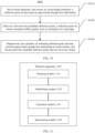
- the detection apparatus 1100 includes a scanning module 1110, an establishing module 1120, an extraction module 1130, and a determining module 1140.
- the scanning module 1110 is configured to scan a surrounding environment of a vehicle by using a LIDAR, to obtain lane line candidate reflection points and road edge information.
- the establishing module 1120 is configured to establish a road edge coordinate system based on the road edge information.
- the extraction module 1130 is configured to extract lane line reflection points from the lane line candidate reflection points based on coordinates of the lane line candidate reflection points in the road edge coordinate system.
- the determining module 1140 is configured to obtain a lane line based on the lane line reflection points.
- the extraction module 1130 may be configured to: determine features of the lane line candidate reflection points based on the coordinates of the lane line candidate reflection points in the road edge coordinate system; and extract the lane line reflection points from the lane line candidate reflection points based on the features of the lane line candidate reflection points.
- the extraction module 1130 may be configured to: perform feature detection through Hough transform based on the coordinates of the lane line candidate reflection points in the road edge coordinate system, to obtain a straight line; and extract, from the lane line candidate reflection points, reflection points whose distances from the straight line are less than a first threshold as the lane line reflection points.
- the extraction module 1130 may be configured to: cluster the lane line candidate reflection points based on the coordinates of the lane line candidate reflection points in the road edge coordinate system; and determine the lane line reflection points based on a clustering result.
- the detection apparatus 1100 may further include: a filtering module, configured to: filter out, from the lane line candidate reflection points, reflection points whose distances from a road edge are greater than a second threshold based on the road edge information before the lane line reflection points are extracted from the lane line candidate reflection points based on the coordinates of the lane line candidate reflection points in the road edge coordinate system.
- a filtering module configured to: filter out, from the lane line candidate reflection points, reflection points whose distances from a road edge are greater than a second threshold based on the road edge information before the lane line reflection points are extracted from the lane line candidate reflection points based on the coordinates of the lane line candidate reflection points in the road edge coordinate system.
- the road edge information includes information about two road edge lines
- the establishing module 1120 may be configured to establish the road edge coordinate system by using a longer edge line in the two road edge lines or a central line of the two road edge lines as a reference line.
- the road edge information includes information about two road edge lines, there is a difference between the two road edge lines, and the road edge coordinate system includes two coordinate systems that are established respectively by using the two road edge lines as reference lines.
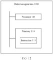
- a detection apparatus provided in an embodiment of this application includes a memory and at least one processor.
- the detection device 1200 may include the memory 114 and the at least one processor 113 that are shown in FIG. 1 .
- the memory 114 is in a signal connection to the at least one processor 113.
- the memory 114 stores instructions 115 executed by the at least one processor 113, and the instructions 115 are executed by the at least one processor 113, to enable the at least one processor 113 to perform the foregoing method for detecting a lane line.
- the processor and the memory may be connected to a bus, or the processor and the memory may be in a signal connection to another external device by using a bus.
- the detection device may include at least one LIDAR and a processor.
- the LIDAR is configured to obtain point cloud data of a surrounding environment of a vehicle.
- the processor is configured to run a software program, and includes a LIDAR sensor driver, a LIDAR lane line perception module, and a lane line receiving module.
- the LIDAR sensor driver is configured to convert data sent by the LIDAR to the processor into three-dimensional point cloud data.
- the LIDAR lane line perception module includes an extraction module, and the extraction module is configured to extract a lane line based on road edge information (a road edge coordinate system).
- the lane line receiving module may be a fusion module, a planning and control module, or the like, and is configured to receive a lane line result. If multi-frame accumulation or tracking is required, an ego-vehicle motion information obtaining module is further required to provide ego-vehicle motion information.
- the ego-vehicle motion information may come from a positioning module or may be obtained by using a vehicle wheel speed meter, a steering wheel rotating angle, and the like.
- the detection device may further include interfaces for connecting components.
- the interfaces may include a high speed interface and a low speed interface.
- the components may be interconnected by using different buses and may be mounted on a common main board or mounted in another manner based on a requirement.
- the processor 113 may process the instructions 115 executed within the detection device 1300, including graphical information instructions stored in the memory 114 or on the memory 114 for display on an external input/output apparatus (such as a display device coupled to an interface).
- the detection device may be a digital computer in various forms and may be fastened in a vehicle.
- the detection device is a laptop computer, a desktop computer, a workbench, a personal digital assistant, a server, a blade server, a mainframe computer, and other suitable computers.
- the detection device may alternatively be a mobile apparatus in various forms, and may be wirelessly connected to a vehicle signal.
- the detection device is a personal digital assistant, a cellular phone, a smartphone, a wearable device, and other similar computing apparatuses.
- the disclosed system, apparatus, device, storage medium, and method may be implemented in other manners.
- the described apparatus embodiments are merely examples.
- division into units is merely logical function division and may be other division during actual implementation.
- a plurality of units or components may be combined or integrated into another system, or some features may be ignored or not performed.
- the displayed or discussed mutual couplings or direct couplings or communication connections may be implemented through some interfaces.
- the indirect couplings or communication connections between the apparatuses or units may be implemented in an electronic form, a mechanical form, or another form.
- the units described as separate parts may or may not be physically separate, and parts displayed as units may or may not be physical units, may be located in one position, or may be distributed on a plurality of network units. Some or all of the units may be selected based on actual requirements to achieve the objectives of the solutions of the embodiments.
Landscapes
- Engineering & Computer Science (AREA)
- Physics & Mathematics (AREA)
- General Physics & Mathematics (AREA)
- Computer Networks & Wireless Communication (AREA)
- Radar, Positioning & Navigation (AREA)
- Remote Sensing (AREA)
- Electromagnetism (AREA)
- Theoretical Computer Science (AREA)
- Multimedia (AREA)
- Computer Vision & Pattern Recognition (AREA)
- Mechanical Engineering (AREA)
- Transportation (AREA)
- Automation & Control Theory (AREA)
- Traffic Control Systems (AREA)
- Data Mining & Analysis (AREA)
- Bioinformatics & Cheminformatics (AREA)
- Bioinformatics & Computational Biology (AREA)
- Artificial Intelligence (AREA)
- Evolutionary Biology (AREA)
- Evolutionary Computation (AREA)
- General Engineering & Computer Science (AREA)
- Life Sciences & Earth Sciences (AREA)
- Optical Radar Systems And Details Thereof (AREA)
- Control Of Driving Devices And Active Controlling Of Vehicle (AREA)
- Length Measuring Devices By Optical Means (AREA)
- Image Analysis (AREA)
Abstract
Description
- This application relates to the field of automated driving, and more specifically, to a method and apparatus for detecting a lane line.
- Artificial intelligence (artificial intelligence, AI) is a theory, a method, a technology, and an application system that simulate, extend, and expand human intelligence by using a digital computer or a machine controlled by a digital computer, sense the environment, obtain knowledge, and use the knowledge to obtain a best result. In other words, artificial intelligence is a branch of computer science, and is intended to understand the essence of intelligence and produce a new intelligent machine that can react in a manner similar to human intelligence. Artificial intelligence is to study design principles and implementation methods of various intelligent machines, so that the machines have perceiving, inference, and decision-making functions. Researches in the field of artificial intelligence include robotics, natural language processing, computer vision, decision-making and inference, human-computer interaction, recommendation and search, basic theories of AI, and the like.
- Automated driving is a mainstream application in the field of artificial intelligence. An automated driving technology relies on cooperation of computer vision, a radar, a monitoring apparatus, a global positioning system, and the like, so that a motor vehicle can implement automated driving without an active manual operation. An automated driving vehicle uses various computing systems to help transport a passenger from one location to another Some automated driving vehicles may require some initial inputs or continuous inputs from an operator (such as a pilot, a driver, or a passenger). An automated driving vehicle allows an operator to switch from a manual operation mode to an automated driving mode or allows a mode between the manual operation mode and the automated driving mode. Because the automated driving technology does not require a human to drive a motor vehicle, a driving error of a human can be effectively avoided theoretically, occurrence of traffic accidents can be reduced, and highway transportation efficiency can be improved. Therefore, the automated driving technology has received increasing attention.
- In the field of automated driving, a vehicle needs to be positioned, to ensure that the vehicle does not deviate from the road. In various road signs, lane lines play an important reference role for ensuring precision of vehicle positioning. Therefore, precision of detecting a lane line directly affects whether the vehicle can be accurately positioned.
- This application provides a method and apparatus for detecting a lane line, to improve precision and stability of detecting a lane line, thereby implementing accurate positioning of a vehicle.
- According to a first aspect, a method for detecting a lane line is provided, including: scanning a surrounding environment of a vehicle by using a LIDAR, to obtain lane line candidate reflection points and road edge information; establishing a road edge coordinate system based on the road edge information; extracting lane line reflection points from the lane line candidate reflection points based on coordinates of the lane line candidate reflection points in the road edge coordinate system; and obtaining a lane line based on the lane line reflection points.
- Because there is a specific association relationship between a road edge and the lane line, the road edge information is used as prior information, so that noise in the lane line candidate reflection points can be effectively filtered out, and precision and stability of detecting the lane line can be improved. In addition, regardless of whether an actual shape of the lane line is regular, distribution of the lane line reflection points in the road edge coordinate system is regular. Therefore, it is easier to extract the lane line reflection points from the road edge coordinate system.
- With reference to the first aspect, in some implementations of the first aspect, before the extracting lane line reflection points from the lane line candidate reflection points based on coordinates of the lane line candidate reflection points in the road edge coordinate system, the method further includes: filtering out, from the lane line candidate reflection points, reflection points whose distances from a road edge are greater than a second threshold based on the road edge information.
- Reflection points on the road edge have features similar to those of the lane line reflection points, that is, both the reflection points on the road edge and the lane line reflection points have strong reflection strength. Therefore, the reflection points on the road edge are usually included in the lane line candidate reflection points as noise. Before the lane line candidate reflection points are processed by using the road edge coordinate system, noise introduced by the road edge may be pre-filtered out based on a distance relationship between the road edge and the candidate reflection points, to improve efficiency of subsequent processing.
- With reference to the first aspect, in some implementations of the first aspect, the road edge information includes information about two road edge lines, and the establishing a road edge coordinate system based on the road edge information includes: establishing the road edge coordinate system by using a longer edge line in the two road edge lines as a reference line.
- The longer edge line is more reliable. When the road edge coordinate system is established by using the longer edge line as the reference line, a result of detecting the lane line is more reliable.
- With reference to the first aspect, in some implementations of the first aspect, the road edge information includes information about two road edge lines, there is a difference between the two road edge lines, and the road edge coordinate system includes two coordinate systems that are established respectively by using the two road edge lines as reference lines.
- When the difference between the two road edge lines is large, the lane line candidate reflection points are separately filtered by using the two coordinate systems, so that a lane line reflection point is not easily missed, and a result of detecting the lane line is more accurate.
- With reference to the first aspect, in some implementations of the first aspect, the extracting lane line reflection points from the lane line candidate reflection points based on coordinates of the lane line candidate reflection points in the road edge coordinate system includes: determining features of the lane line candidate reflection points based on the coordinates of the lane line candidate reflection points in the road edge coordinate system; and extracting the lane line reflection points from the lane line candidate reflection points based on the features of the lane line candidate reflection points.
- The features of the lane line candidate reflection points may include one or more of the following features: orientations of the lane line candidate reflection points, distances between the lane line candidate reflection points and the road edge, spacings between the lane line candidate reflection points, whether the lane line candidate reflection points can form a straight line, and the like.
- With reference to the first aspect, in some implementations of the first aspect, the road edge information includes information about two road edge lines, and the establishing a road edge coordinate system based on the road edge information includes: establishing the road edge coordinate system by using a central line of the two road edge lines as a reference line.
- With reference to the first aspect, in some implementations of the first aspect, the determining features of the lane line candidate reflection points based on the coordinates of the lane line candidate reflection points in the road edge coordinate system includes: performing feature detection through Hough transform based on the coordinates of the lane line candidate reflection points in the road edge coordinate system, to obtain a straight line; and the extracting the lane line reflection points from the lane line candidate reflection points based on the features of the lane line candidate reflection points includes: extracting, from the lane line candidate reflection points, reflection points whose distances from the straight line are less than a first threshold as the lane line reflection points.
- With reference to the first aspect, in some implementations of the first aspect, the extracting lane line reflection points from the lane line candidate reflection points based on coordinates of the lane line candidate reflection points in the road edge coordinate system includes: clustering the lane line candidate reflection points based on the coordinates of the lane line candidate reflection points in the road edge coordinate system; and determining the lane line reflection points based on a clustering result.
- According to a second aspect, an apparatus for detecting a lane line is provided, including modules configured to perform the detection method in the first aspect.
- According to a third aspect, an apparatus for detecting lane line is provided, including: at least one processor; and a memory, in a signal connection to the at least one processor. The memory stores instructions executed by the at least one processor, and the instructions are executed by the at least one processor, to enable the at least one processor to perform the detection method in the first aspect.
- According to a fourth aspect, a chip is provided, where the chip includes a processor and a data interface, and the processor reads, by using the data interface, instructions stored in a memory, to perform the method in the first aspect.
- Optionally, in an implementation, the chip may further include the memory, the memory stores the instructions, the processor is configured to execute the instructions stored in the memory, and when the instructions are executed, the processor is configured to perform the method in the first aspect.
- According to a fifth aspect, this application provides a computer-readable storage medium. The computer-readable storage medium stores instructions, and when the instructions are run on a computer, the computer is enabled to perform the method according to the first aspect.
- According to a sixth aspect, a computer program product that includes instructions is provided. When the instructions are run on a computer, the computer is enabled to perform the method according to the first aspect.
- According to a seventh aspect, a vehicle is provided. The vehicle includes the detection apparatus in the second aspect or the third aspect.
-
-
FIG. 1 is a functional block diagram of a vehicle according to an embodiment of this application; -
FIG. 2 is a schematic diagram of a structure of an automated driving system according to an embodiment of this application; -
FIG. 3 is a schematic diagram of a specific structure of anenvironmental perception module 220 inFIG. 2 ; -
FIG. 4 is a schematic flowchart of a method for detecting a lane line according to an embodiment of this application; -
FIG. 5 is a schematic flowchart of a possible implementation of step S410 inFIG. 4 ; -
FIG. 6 is a schematic diagram of distribution of lane line candidate reflection points in an ego-vehicle coordinate system; -
FIG. 7 is a schematic diagram of distribution of lane line candidate reflection points in a road edge coordinate system; -
FIG. 8 is a schematic flowchart of a possible implementation of step S430 inFIG. 4 ; -
FIG. 9 is a schematic flowchart of another possible implementation of step S430 inFIG. 4 ; -
FIG. 10 is a schematic flowchart of still another possible implementation of step S430 inFIG. 4 ; -
FIG. 11 is a schematic diagram of a structure of an apparatus for detecting a lane line according to an embodiment of this application; and -
FIG. 12 is a schematic diagram of a structure of an apparatus for detecting a lane line according to another embodiment of this application. - A method for detecting a lane line provided in this application may be applied to a vehicle having an automated driving function. With reference to
FIG. 1 , the following describes in detail a specific structure of the vehicle having the automated driving function. -
FIG. 1 is a functional block diagram of avehicle 100 according to an embodiment of this application. In an embodiment, thevehicle 100 is configured into a complete or partial automated driving mode. For example, thevehicle 100 in the automated driving mode may control thevehicle 100. A manual operation may be performed to determine current states of the vehicle and a surrounding environment of the vehicle, determine possible behavior of at least one another vehicle in the surrounding environment, determine a confidence level corresponding to a possibility that the another vehicle performs the possible behavior, and control thevehicle 100 based on determined information. When thevehicle 100 is in the automated driving mode, thevehicle 100 may be set to operate when there is no interaction with a human. - The
vehicle 100 may include various subsystems, for example, atravel system 102, asensing system 104, acontrol system 106, one or moreperipheral devices 108 and apower supply 110, a computer system 112, and auser interface 116. Optionally, thevehicle 100 may include more or fewer subsystems, and each subsystem may include a plurality of elements. In addition, each subsystem and element of thevehicle 100 may be interconnected in a wired or wireless manner. - The
travel system 102 may include a component providing power motion to thevehicle 100. In an embodiment, thetravel system 102 may include anengine 118, anenergy source 119, a transmission device 120, and a wheel (or tire) 121. Theengine 118 may be an internal combustion engine, an electric motor, an air compression engine, or a combination of other types of engines, for example, a hybrid engine including a gasoline engine and an electric motor, or a hybrid engine including an internal combustion engine and an air compression engine. Theengine 118 converts theenergy source 119 into mechanical energy. - Examples of the
energy source 119 include gasoline, diesel, other petroleum-based fuel, propane, other compressed gas-based fuel, ethanol, a solar panel, a battery, and other power supply. Theenergy source 119 may also provide energy to other systems of thevehicle 100. - The transmission device 120 may transmit mechanical power from the
engine 118 to thewheel 121. The transmission device 120 may include a gear box, a differential, and a drive shaft. In an embodiment, the transmission device 120 may further include other devices, such as a clutch. The drive axle may include one or more shafts that may be coupled to one ormore wheels 121. - The
sensing system 104 may include several sensors that sense information about a surrounding environment of thevehicle 100. For example, thesensing system 104 may include a global positioning system 122 (the global positioning system may be a GPS system, a Beidou system, or another positioning system), an inertial measurement unit (inertial measurement unit, IMU) 124, aradar 126, alaser rangefinder 128, and acamera 130. Thesensing system 104 may further include sensors (for example, an in-vehicle air quality monitor, a fuel gauge, and an oil temperature gauge) of an internal system of the monitoredvehicle 100. Sensor data from one or more of these sensors may be used for detecting an object and corresponding characteristics (a position, a shape, a direction, a speed, and the like) of the object. The detection object includes detection and identification of a road structure and other objects located on the road. The detection and identification are key functions of safe operation of theautomated driving vehicle 100. - The
positioning system 122 may be configured to estimate a geographic location of thevehicle 100. TheIMU 124 is configured to sense changes in a position and a direction of thevehicle 100 based on inertial acceleration. In an embodiment, theIMU 124 may be a combination of an accelerometer and a gyroscope. - The
radar 126 may sense an object in the surrounding environment of thevehicle 100 by using a radio signal. In some embodiments, in addition to sensing an object, theradar 126 may also be configured to sense a speed and/or an advancing direction of the object. - The
laser rangefinder 128 may sense an object in an environment in which thevehicle 100 is located by using laser. In some embodiments, thelaser rangefinder 128 may include one or more laser sources, a laser scanner, one or more detectors, and another system component. - The
camera 130 may be configured to capture a plurality of images of the surrounding environment of thevehicle 100. Thecamera 130 may be a still camera or a video camera. - The
control system 106 may be configured to control operations of both thevehicle 100 and the components of thevehicle 100. Thecontrol system 106 may include various elements, including asteering system 132, athrottle 134, abraking unit 136, a sensor fusion algorithm 138, acomputer vision system 140, aroute control system 142, and an obstacle avoidance system 144. - The
steering system 132 may be configured to adjust an advancement direction of thevehicle 100. For example, in an embodiment, thesteering system 132 may be a steering wheel system. - The
throttle 134 is configured to: control an operating speed of theengine 118 and further control a speed of thevehicle 100. - The
braking unit 136 is configured to control thevehicle 100 to decelerate. Thebraking unit 136 may use friction to slow down the rotation of thewheel 121. In another embodiment, thebraking unit 136 may convert kinetic energy of thewheel 121 into an electric current. Alternatively, thebraking unit 136 may slow down the rotation of thewheel 121 in another manner to control the speed of thevehicle 100. - The
computer vision system 140 may be configured to process and analyze information such as images captured by thecamera 130 and road information reflection points provided by the sensing system, to identify objects and/or features in the surrounding environment of thevehicle 100. The objects and/or features may include traffic signals, road boundaries, and obstacles. Thecomputer vision system 140 may use an object recognition algorithm, a structure from motion (Structure from Motion, SFM) algorithm, video tracking, and other computer vision technologies. In some embodiments, thecomputer vision system 140 may be configured to draw a map for an environment, track an object, estimate a speed of an object, and the like. - The
route control system 142 is configured to determine a travel route of thevehicle 100. In some embodiments, theroute control system 142 may determine the travel route for thevehicle 100 with reference to data from the sensor fusion algorithm 138, thepositioning system 122, and one or more predetermined maps. - The obstacle avoidance system 144 is configured to recognize, evaluate, and avoid or surmount, in other manners, potential obstacles in the environment of the
vehicle 100. - Certainly, in an embodiment, the
control system 106 may additionally or replaceably include components other than those shown and described inFIG. 1 , or may not include some of the components shown inFIG. 1 . - The
vehicle 100 interacts with an external sensor, another vehicle, another computer system, or a user by using theperipheral device 108. Theperipheral device 108 may include a wireless communications system 146, a vehicle-mounted computer 148, amicrophone 150, and/or aspeaker 152. - In some embodiments, the
peripheral device 108 provides a means for a user of thevehicle 100 to interact with theuser interface 116. For example, the vehicle-mounted computer 148 may provide information to the user of thevehicle 100. Theuser interface 116 may also operate the vehicle-mounted computer 148 to receive a user input. The vehicle-mounted computer 148 may be operated by using a touchscreen. In other cases, theperipheral device 108 may provide a means for thevehicle 100 to communicate with other devices located in the vehicle. For example, themicrophone 150 may receive audio (for example, a voice command or another audio input) from the user ofvehicle 100. Similarly, thespeaker 152 may output audio to the user of thevehicle 100. - The wireless communications system 146 may perform wireless communication with one or more devices directly or through a communications network. For example, the wireless communications system 146 may use 3G cellular communication such as CDMA, EVD0, or GSM/GPRS, use 4G cellular communication such as LTE, or use 5G cellular communication. The wireless communications system 146 may communicate with a wireless local area network (wireless local area network, WLAN) by using Wi-Fi. In some embodiments, the wireless communications system 146 may communicate directly with a device by using an infrared link, Bluetooth, or ZigBee. Other wireless protocols, such as various vehicle communications systems, for example, the wireless communications system 146 may include one or more dedicated short range communications (dedicated short range communications, DSRC) devices, which may include public and/or private data communication between vehicles and/or roadside stations.
- The
power supply 110 may provide power to various components of thevehicle 100. In an embodiment, thepower supply 110 may be a rechargeable lithium-ion or lead-acid battery. One or more battery packs of such batteries may be configured to provide power to various components of thevehicle 100. In some embodiments, thepower supply 110 and theenergy source 119 may be implemented together, such as in some all-electric vehicles. - Some or all of the functions of the
vehicle 100 are controlled by the computer system 112. The computer system 112 may include at least oneprocessor 113. Theprocessor 113 executes aninstruction 115 stored in a non-transitory computer-readable medium such as amemory 114. The computer system 112 may alternatively be a plurality of computing devices that control individual components or subsystems of thevehicle 100 in a distributed manner. - The
processor 113 may be any conventional processor, such as a commercially available CPU. Optionally, the processor may be a dedicated device such as an ASIC or another hardware-based processor. AlthoughFIG. 1 functionally illustrates other elements of the processor, the memory, and the computer system 112 in a same block, a person of ordinary skill in the art should understand that the processor, the computer, or the memory may actually include a plurality of processors, computers, or memories that may or may not be stored in a same physical housing. For example, the memory may be a hard disk drive or another storage medium located in a housing different from that of the computer system 112. Therefore, a reference to a processor or a computer is understood to include a reference to a set of processors, computers, or memories that may or may not be operated in parallel. Different from using a single processor to perform the steps described herein, some components, such as a steering component and a deceleration component, may each have its own processor that performs only calculation related to component-specific functions. - In various aspects described herein, the processor may be located far away from the vehicle and perform wireless communication with the vehicle. In another aspect, some of processes described herein are performed on a processor arranged in the vehicle, while others are performed by a remote processor, including taking a necessary step to perform a single manipulation.
- In some embodiments, the
memory 114 may include the instruction 115 (for example, program logic), and theinstruction 115 may be executed by theprocessor 113 to perform various functions of thevehicle 100, including the functions described above. Thememory 114 may also include additional instructions, including instructions used to send data to, receive data from, interact with, and/or control one or more of thetravel system 102, thesensing system 104, thecontrol system 106, and theperipheral device 108. - In addition to the
instruction 115, thememory 114 may further store data, such as a road map, route information, a location, a direction, a speed, and other vehicle data of the vehicle, and other information. Such information may be used by thevehicle 100 and the computer system 112 during operation of thevehicle 100 in autonomous, semi-autonomous, and/or manual modes. - For example, after the surrounding environment of the vehicle is scanned by using the
radar 126, thememory 114 may store point cloud data formed by reflection points. Thevehicle 100 or the computer system 112 may find lane line reflection points from point cloud, to determine a position of a lane line. Next, thevehicle 100 or the computer system 112 may position or control thevehicle 100 based on the lane line. - The
user interface 116 is configured to provide information to or receive information from the user of thevehicle 100. Optionally, theuser interface 116 may include one or more input/output devices in a set ofperipheral devices 108, such as the wireless communications system 146, the vehicle-mounted computer 148, themicrophone 150, and thespeaker 152. - The computer system 112 may control the functions of the
vehicle 100 based on inputs received from various subsystems (for example, thetravel system 102, thesensing system 104, and the control system 106) and theuser interface 116. For example, the computer system 112 may control, by using an input from thecontrol system 106, thesteering system 132 to avoid obstacles detected by thesensing system 104 and the obstacle avoidance system 144. In some embodiments, the computer system 112 is operable to provide control over many aspects of thevehicle 100 and the subsystems of thevehicle 100. - Optionally, one or more of these components may be mounted separate from the
vehicle 100 or may be associated with thevehicle 100. For example, thememory 114 may exist partially or completely separate from thevehicle 100. The components may be communicatively coupled together in a wired and/or wireless manner. - Optionally, the foregoing components are merely an example. During actual application, components in the foregoing modules may be added or deleted based on an actual requirement.
FIG. 1 should not be construed as a limitation on the embodiments of this application. - An automated driving vehicle traveling on a road, such as the foregoing
vehicle 100, may recognize an object in the surrounding environment of thevehicle 100, to determine adjustment on a current speed. The object may be another vehicle, a traffic control device, or another type of object. In some examples, each recognized object may be considered independently, and based on respective characteristics of the object, such as a current speed of the object, an acceleration of the object, a distance from the vehicle, a speed to be obtained after adjustment by the automated driving vehicle may be determined. - Optionally, the
automated driving vehicle 100 or a computing device (such as the computer system 112, thecomputer vision system 140, and thememory 114 inFIG. 1 ) associated with theautomated driving vehicle 100 may predict behavior of the identified object based on the characteristic of the identified object and a status (for example, traffic, rain, or ice on a road) of the ambient environment. Optionally, each recognized object depends on the behavior of each other. Therefore, the behavior of a single recognized object may alternatively be predicted by considering all the recognized objects together. Thevehicle 100 can adjust the speed of thevehicle 100 based on the predicted behavior of the recognized object. In other words, the automated driving vehicle can determine, based on the predicted behavior of the object, a specific stable state (for example, acceleration, deceleration, or stop) to which the vehicle needs to be adjusted. In this process, other factors may also be taken into account to determine the speed of thevehicle 100, such as a lateral position of thevehicle 100 in the road on which it travels (in a direction perpendicular to a road extending direction), a curvature of the road, proximity between static and dynamic objects, and the like. - In addition to providing an instruction for adjusting the speed of the automated driving vehicle, the computing device may further provide an instruction for modifying a steering angle of the
vehicle 100, so that the automated driving vehicle can follow a given track and/or maintain a safe horizontal distance and a safe vertical distance from an object (for example, a car on a neighboring lane of the road) near the automated driving vehicle. - The
vehicle 100 may be a car, a truck, a motorcycle, a bus, a boat, an airplane, a helicopter, a lawn mower, a recreational vehicle, a playground vehicle, a construction device, a tram, a golf cart, a train, a cart, or the like. This is not particularly limited in embodiments of this application. - The method for detecting a lane line provided in this application may be applied to an automated driving system of a vehicle. The following describes the automated driving system in detail with reference to
FIG. 2 and FIG. 3 . It should be noted that, aLIDAR 210 inFIG. 2 and FIG. 3 may be a part of thesensing system 104 inFIG. 1 , for example, may be a specific form of theradar 126 inFIG. 1 . Anenvironmental perception module 220, apositioning module 230, and a planning andcontrol module 240 inFIG. 2 may be implemented by thecontrol system 106 inFIG. 1 , may be implemented by the computer system 112 inFIG. 1 , or may be implemented by both. An acceleration/deceleration and steering apparatus 250 inFIG. 2 may be a part of thetravel system 102. - As shown in
FIG. 2 , the LIDAR 210 (or referred to as a LIDAR sensor) may be configured to scan the surrounding environment of the vehicle. For example, the LIDAR may scan a road surface on which the vehicle travels. Then, theLIDAR 210 may transmit received scanning information to theenvironmental perception module 220 and thepositioning module 230. The scanning information may include, for example, information about reflection points formed by reflecting, by an obstacle around the vehicle (such as a road surface or other vehicles), laser emitted by the LIDAR. - The
positioning module 230 may process the scanning information to perceive a position, an orientation, and the like of the vehicle in the road. - As shown in
FIG. 3 , theenvironmental perception module 220 may include anobject perception module 221, a drivablearea perception module 222, and a road structureinformation perception module 223. - The
object perception module 221 may detect information about other vehicles on the road based on the scanning information input by theLIDAR 210. For example, information that can reflect distances between vehicles may be detected. - The drivable
area perception module 222 may detect information such as a traffic state of the road and a drivable area of the vehicle based on the scanning information input by theLIDAR 210. - The road structure
information perception module 223 may detect a structure of the road based on the scanning information input by theLIDAR 210. The road structureinformation perception module 223 may include a laneline perception module 224. The laneline perception module 224 may process the scanning information to extract information about a lane line, thereby implementing perception on the lane line. - The planning and
control module 240 may receive processing results of theenvironmental perception module 220 and thepositioning module 230, and analyze the processing results, to control the acceleration/deceleration and steering apparatus 250. For example, the planning andcontrol module 240 may perform accurate path planning based on information about a lane line perceived by the laneline perception module 224, and control a driving state of the vehicle by using the acceleration and steering apparatus 250. - It can be learned from the foregoing description that accurate detection of a lane line is of great significance for automated driving of vehicles. To detect a lane line, in the related technology, the surrounding environment of the vehicle is first scanned by using the LIDAR, and lane line candidate reflection points are extracted based on strength information of laser reflection points. Because the lane line candidate reflection points include a large amount of noise, after the lane line candidate reflection points are obtained, in the related technology, the noise in the lane line candidate reflection points is filtered out in a specific manner, to obtain lane line reflection points. A position of the lane line can then be determined based on the lane line reflection points.
- However, in the related technology, when the lane line reflection points are extracted from the lane line candidate reflection points, road edge information is not fully used, and in the related technology, the lane line reflection points are mainly extracted from an ego-vehicle coordinate system. These all lead to insufficient accuracy and reliability of the extracted lane line reflection points.
- With reference to
FIG. 4 , the following describes in detail a method for detecting a lane line according to an embodiment of this application. The method for detecting a lane line provided inFIG. 4 may be applied to an automated driving system of a vehicle, for example, may be applied to theenvironmental perception module 220 of the automated driving system shown inFIG. 2 . As shown inFIG. 4 , the method includes steps S410 to S440. The following describes the steps in detail. - In step S410, a surrounding environment of a vehicle is scanned by using a LIDAR, to obtain lane line candidate reflection points and road edge information. For example, the surrounding environment of the vehicle is first scanned by using the LIDAR, and reflection points are obtained. Then, the lane line candidate reflection points and the road edge information may be obtained based on strength information of the reflection points and features of the reflection points and adjacent reflection points. For a specific implementation of step S410, refer to
FIG. 5 . - In step S420, a road edge coordinate system is established based on the road edge information. The road edge information may be information about road edge lines, for example, information such as positions and lengths of the road edge lines, and a difference between two road edge lines. The road edge coordinate system may be a two-dimensional rectangular coordinate system established by using the road edge line as a reference line, or may be a Frenet coordinate system. For example, the road edge coordinate system may be a coordinate system established by using the road edge line as an axis of the two-dimensional rectangular coordinate system.
- In step S430, lane line reflection points are extracted from the lane line candidate reflection points based on coordinates of the lane line candidate reflection points in the road edge coordinate system. Before step S430 is performed, the lane line candidate reflection points may be first projected from a current coordinate system (for example, the ego-vehicle coordinate system) into the road edge coordinate system, and then the lane line candidate reflection points are processed in the road edge coordinate system.
- There may be a plurality of implementations of step S430. For example, features of the lane line candidate reflection points may be first determined based on the coordinates of the lane line candidate reflection points in the road edge coordinate system; and then the lane line reflection points are extracted from the lane line candidate reflection points based on the features of the lane line candidate reflection points. The features of the lane line candidate reflection points include one or more of the following features: orientations of the lane line candidate reflection points, distances between the lane line candidate reflection points and the road edge line, spacings between the lane line candidate reflection points, whether the lane line candidate reflection points can form a straight line, and the like. Alternatively, the lane line candidate reflection points may be clustered in the road edge coordinate system, and then the lane line reflection points are extracted from the lane line candidate reflection points based on a clustering result.
FIG. 8 to FIG. 10 in the following provide several possible implementations of step S430. - In step S440, the lane line is obtained based on the lane line reflection points. For example, the lane line reflection points may be transformed into the ego-vehicle coordinate system, and then the lane line is fitted in the ego-vehicle coordinate system. After the lane line is obtained, the lane line may be directly output, or the lane line may be output after being tracked. Information about the lane line obtained in step S440 may be output to the planning and
control module 240 shown inFIG. 2 , for the planning andcontrol module 240 to perform path planning and/or steering control of the vehicle. - Because there is a specific association relationship between a road edge and the lane line, the road edge information is used as prior information, so that noise in the lane line candidate reflection points can be effectively filtered out, and precision and stability of detecting the lane line can be improved. In addition, regardless of whether an actual shape of the lane line is regular, distribution of the lane line reflection points in the road edge coordinate system is regular. Therefore, it is easier to extract the lane line reflection points from the road edge coordinate system.
- The following provides a possible implementation of step S410 with reference to
FIG. 5. FIG. 5 includes step S510 to step S530. The following describes these steps in detail. - In step S510, point cloud is obtained and preprocessed.
- There may be a plurality of manners of obtaining and preprocessing the point cloud. For example, in some embodiments, the LIDAR may be used to scan the surrounding environment by one or more layers, to obtain the point cloud formed by reflection points. Then, a ground model is established based on the point cloud, and some obvious noise is filtered out based on the ground model.
- For example, the reflection points in the point cloud may be projected into two-dimensional grids, and lowest and highest heights of reflection points projected into each grid relative to the ground are calculated. If a height difference between the highest height and the lowest height is less than a threshold (for example, 0.1 m), the lowest height of the grid relative to the ground may be considered as a ground height of the grid. After ground heights of all the grids are determined, the ground model is established. Then, a height of each reflection point relative to the ground may be calculated based on the ground model, and reflection points whose heights relative to the ground exceed a threshold (for example, 2 m) are filtered out.
- In step S520, the road edge information is extracted. For example, in some embodiments, road edge candidate reflection points may be extracted based on features of the reflection points and adjacent points in the point cloud. Then, noise in the road edge candidate reflection points may be removed to obtain road edge line reflection points. Next, the road edge lines may be detected based on the road edge line reflection points, to obtain the road edge information.
- For example, the road edge information may be extracted by using the following steps.
- Step a: Extract the road edge candidate reflection points from the point cloud. For example, the road edge candidate reflection points may be extracted based on the features of the reflection points and the adjacent reflection points. The features of the reflection points and the adjacent reflection points may include one or more of the following features: a height change, an angle change, a distance difference, and the like between the reflection points.
- Step b: Cluster the road edge candidate reflection points, and filter out a cluster whose quantity of reflection points is less than a specific threshold.
- Step c: Perform least square fitting on each cluster to form a fitted line. Then, a distance between each reflection point in the cluster and the fitted line may be calculated, and one or more reflection points with a largest distance or a large distance are removed from the cluster. In this way, precision of the fitted line can be improved, so that reliability of the subsequently extracted road edge information is improved.
- Step d: Repeat step c until distances between all the reflection points in the road edge candidate reflection points and the corresponding fitted line are less than a specific threshold.
- Step e: Output the fitted line as the road edge line.
- In step S530, the lane line candidate reflection points are extracted. For example, in some embodiments, the lane line candidate reflection points may be extracted based on the features of the reflection points and the adjacent reflection points in the point cloud.
- For example, the lane line candidate reflection points may be extracted by using the following steps.
- Step a: For a reflection point, determine a height of the reflection point relative to the ground based on the ground model established in step S510, and if the height relative to the ground meets a threshold (for example, 0.1 m), proceed to step b; otherwise, select a next reflection point.
- Step b: Select adjacent reflection points of the reflection point in a specific range, and calculate a maximum reflection strength ϕmax and a minimum reflection strength ϕmin of the reflection points in the specific range. For example, the reflection point and five reflection points on the left of the reflection point and five reflection points on the right of the reflection point, namely, a total of 11 reflection points may be selected, and the maximum reflection strength ϕmax and the minimum reflection strength ϕmin in the 11 reflection points are calculated.
- Step c: Determine whether the reflection strength ϕ of the reflection point meets ϕ>β(ϕmax-ϕmin)+ϕmin. β is a preset threshold, for example, may be 0.9. If the foregoing condition is met, the reflection point is a lane line candidate reflection point; or if the condition is not met, a next reflection point is selected, and steps a to c are repeatedly performed until all the reflection points in the point cloud are traversed.
- Refer to
FIG. 4 again. The road edge coordinate system mentioned in step S420 may be established in a plurality of manners. The following provides detailed descriptions with reference toFIG. 6 andFIG. 7 . -
FIG. 6 is an ego-vehicle coordinate system established based on a position and an advancement direction of the vehicle. A positive direction of the x-axis is the advancement direction of the vehicle, and the y-axis is perpendicular to the advancement direction of the vehicle. In the ego-vehicle coordinate system shown inFIG. 6 , two road edge lines are respectively road edge lines a and b, and both the road edge lines a and b are curves. - In some embodiments, the road edge coordinate system may be established by using the road edge line b in
FIG. 6 as a reference line, and the established road edge coordinate system is shown inFIG. 7 . InFIG. 7 , the x' axis is the road edge line b. It can be learned fromFIG. 7 that lane line candidate reflection points that are originally arranged in a curve are arranged in a straight line inFIG. 7 . Therefore, it is easier to extract the lane line reflection points in the road edge coordinate system. -
FIG. 7 is a road edge coordinate system established by using one of the two road edge lines as a reference line. When lengths of the two road edge lines are different, the road edge line used as the reference line may be a longer one of the two road edge lines. A real road edge line is usually long. Therefore, a probability that the longer road edge line is the real road edge line is higher, and the road edge coordinate system established by using the longer edge line as the reference line is more reliable. - In addition, in some embodiments, the road edge coordinate system may alternatively be established by using a central line of the two road edge lines as a reference line. Alternatively, in some embodiments, if a difference between the two road edge lines is large, two coordinate systems may be established respectively by using the two road edge lines as reference lines, and lane line reflection points filtered from the two coordinate systems are fused. When the difference between the two road edge lines is large, the lane line candidate reflection points are separately filtered by using the two coordinate systems, so that a lane line reflection point is not easily missed, and a result of detecting the lane line is more accurate.
- Refer to
FIG. 4 again. There may be a plurality of manners of extracting the lane line reflection points mentioned in step S430. With reference toFIG. 8 to FIG. 10 , the following provides several possible implementations of step S430. -
FIG. 8 is a schematic flowchart of a possible implementation of step S430 inFIG. 4 . Steps ofFIG. 8 include step S810 and step S820. - In step S810, feature detection is performed through Hough transform based on the coordinates of the lane line candidate reflection points in the road edge coordinate system, to obtain a straight line.
- In the road edge coordinate system, a shape of the lane line presents a regular state, such as a straight line state. Therefore, the Hough transform may be used to find straight line features of the lane line candidate reflection points.
- In step S820, reflection points whose distances from the straight line are less than a threshold are extracted from the lane line candidate reflection points as the lane line reflection points. The distances between the lane line candidate reflection points and the straight line may be distances between horizontal coordinates and/or vertical coordinates of the lane line candidate reflection points and the straight line.
- With reference to
FIG. 6 andFIG. 7 , the following provides a specific implementation of the embodiment inFIG. 8 . - As shown in
FIG. 6 , the road edge lines a and b are curves in an actual environment. The curves may be represented by using a quadratic or higher order polynomial function. For example, an expression of the road edge line a is y=10+0.1x+0.01x2, and an expression of the other road edge line b is y=-10+0.1x+0.01x2. - Assuming that coordinates of a lane line candidate reflection point in the ego-vehicle coordinate system (a unit of coordinate values may be m) are (x, y), in the road edge coordinate system shown in
FIG. 7 , the coordinates of the lane line candidate reflection point are converted into (x', y'). A numerical relationship between (x', y') and (x, y) meets:

- Assuming that coordinates of the lane line candidate reflection points in the coordinate system in
FIG. 6 are as follows: - (x=0, y=0)
- (x=10, y=2)
- (x=20, y=6)
- (x=30, y=12)
- (x=40, y=20)
- (x=40, y=23)
- (x=50, y=30)
- (x'=0, y'=10)
- (x'=10, y'=10)
- (x'=20, y'=10)
- (x'=30, y'=10)
- (x'=40, y'=10)
- (x'=40, y'=13)
- (x'=50, y'=10)
- As shown in
FIG. 7 , in the road edge coordinate system, a straight line c is first found by using the Hough transform. End points of the straight line c are respectively (0, 10) and (50, 10). - Then, a distance from each lane line candidate reflection point to the straight line c is calculated. A point whose distance from the straight line c is less than a specific preset threshold (for example, 0.1 m) is marked as a lane line reflection point, and a reflection point that is far away from the straight line, such as a point (x'=40, y'=13) in
FIG. 7 , is removed. Finally, the lane line reflection points extracted from the lane line candidate reflection points are: - (x'=0, y'=10)
- (x'=10, y'=10)
- (x'=20, y'=10)
- (x'=30, y'=10)
- (x'=40, y'=10)
- (x'=50, y'=10)
- With reference to
FIG. 8 , how to extract the lane line reflection points in the road edge coordinate system by using the Hough transform is described in detail above. With reference toFIG. 9 andFIG. 10 , the following describes in detail how to extract the lane line reflection points in a clustering manner in the road edge coordinate system. -
FIG. 9 is a schematic flowchart of another possible implementation of step S430 inFIG. 4 .FIG. 9 includes steps S910 to S940, which are specifically described as follows. - In step S910, a lane line candidate reflection point is selected as a seed point A, and a cluster M1 is created. A belongs to M1.
- In step S920, remaining lane line candidate reflection points are traversed. For example, starting from a lane line candidate reflection point B, a relative lateral distance and/or a relative longitudinal distance between the candidate reflection point and the lane line candidate reflection point A in the cluster M1 are determined. If a preset lateral distance threshold and/or longitudinal distance threshold are met, the lane line candidate reflection point B is classified into the cluster M1. Continue to determine a next lane line candidate reflection point, for example, a lane line candidate reflection point C. The rest can be deduced by analogy.
- In step S930, a lane line candidate reflection point is selected from lane line candidate reflection points that have not been classified into any cluster, a cluster M2 is created, and step S920 is repeated.
- In step S940, step S930 is repeated until all the lane line candidate reflection points are traversed.
- Finally obtained reflection points in the clusters are the lane line reflection points.
- Optionally, in some embodiments, quadratic or cubic curve fitting may be performed on candidate reflection points in a cluster, to filter out, from the cluster, candidate reflection points whose lateral distance from a fitted curve is large.
- Optionally, in some embodiments, a cluster with a small quantity of candidate reflection points may be filtered out, or a cluster with a small distribution distance in the x direction of the road edge coordinate system may be filtered out.
- Optionally, in some embodiments, clusters may be filtered out or merged based on a lateral spacing between the clusters.
-
FIG. 10 is a schematic flowchart of still another possible implementation of step S430 inFIG. 4 .FIG. 10 includes steps S 1010 to S 1040, which are specifically described as follows. - In step S1010, an initial parameter is set, and a reflection point set that meets an approximate straight line relationship is extracted by using the Hough transform. The initial parameter may include a quantity of points in the reflection point set, or a distance between adjacent points in the reflection point set.
- In
step S 1020, a reflection point set whose orientation differs greatly from an orientation of the road edge line is filtered out from the lane line candidate reflection points. Optionally, in some embodiments, a reflection point set with a large spacing from other reflection point sets may be deleted based on lateral spacings between the reflection point sets, or some reflection point sets with small spacings may be merged based on the lateral spacings between the reflection point sets. - In step S 1030, a plurality of remaining reflection point sets that meet the approximate straight line relationship are respectively used as initial clusters, and lane line candidate reflection points that are not in any cluster are traversed.
- For example, for a lane line candidate reflection point C, relative lateral distances and/or relative longitudinal distance between the lane line candidate reflection point C and reflection points in all the initial clusters are determined (or, relative normal distances and relative tangential distances may alternatively be used to replace the relative lateral distances and/or the relative longitudinal distances). If the relative lateral distances and/or the relative longitudinal distances between the lane line candidate reflection point C and the reflection points in a cluster M1 in the initial clusters meet a specified lateral distance threshold and/or longitudinal distance threshold, a quantity of the points that are in the cluster M1 and that meet the specified lateral distance threshold and/or longitudinal distance threshold is further calculated. If the quantity of the reflection points in the cluster M1 meets a specified threshold, the point C may be classified into the cluster M1. The rest can be deduced by analogy.
- Optionally, in some embodiments, in addition to traversing the lane line candidate reflection points, some other reflection points in the initially obtained point cloud, for example, reflection points close to the initial cluster, may be further traversed.
- After the foregoing, finally obtained reflection points in the clusters are the lane line reflection points.
- Refer to
FIG. 4 again. In some embodiments, after the road edge information is obtained, reliability of the road edge information may be first determined. If the road edge information is reliable, the solution provided in this embodiment of this application may be used to extract the lane line reflection points from the road edge coordinate system. Otherwise, the lane line reflection points may be extracted from the ego-vehicle coordinate system. Whether the road edge information is reliable may be measured in a plurality of manners. For example, the reliability of the road edge information may be determined by determining whether the two road edge lines are sufficiently long, whether the difference between the two road edge lines is sufficiently small, or the like. - It should be noted that the scanning by using the LIDAR in step S410 may be single-frame scanning, or may be multi-frame scanning. When the road edge information or the lane line information is extracted by using a multi-frame scanning result of the LIDAR, accuracy of an extraction result can be improved.
- The following describes apparatus embodiments of this application. Because the apparatus embodiments correspond to the method embodiments, for parts that are not described in detail, refer to the foregoing method embodiments.
-
FIG. 11 is a schematic diagram of a structure of an apparatus for detecting a lane line according to an embodiment of this application. As shown inFIG. 11 , the detection apparatus 1100 includes ascanning module 1110, anestablishing module 1120, anextraction module 1130, and a determiningmodule 1140. Thescanning module 1110 is configured to scan a surrounding environment of a vehicle by using a LIDAR, to obtain lane line candidate reflection points and road edge information. Theestablishing module 1120 is configured to establish a road edge coordinate system based on the road edge information. Theextraction module 1130 is configured to extract lane line reflection points from the lane line candidate reflection points based on coordinates of the lane line candidate reflection points in the road edge coordinate system. The determiningmodule 1140 is configured to obtain a lane line based on the lane line reflection points. - Optionally, in some embodiments, the
extraction module 1130 may be configured to: determine features of the lane line candidate reflection points based on the coordinates of the lane line candidate reflection points in the road edge coordinate system; and extract the lane line reflection points from the lane line candidate reflection points based on the features of the lane line candidate reflection points. - Optionally, in some embodiments, the
extraction module 1130 may be configured to: perform feature detection through Hough transform based on the coordinates of the lane line candidate reflection points in the road edge coordinate system, to obtain a straight line; and extract, from the lane line candidate reflection points, reflection points whose distances from the straight line are less than a first threshold as the lane line reflection points. - Optionally, in some embodiments, the
extraction module 1130 may be configured to: cluster the lane line candidate reflection points based on the coordinates of the lane line candidate reflection points in the road edge coordinate system; and determine the lane line reflection points based on a clustering result. - Optionally, in some embodiments, the detection apparatus 1100 may further include: a filtering module, configured to: filter out, from the lane line candidate reflection points, reflection points whose distances from a road edge are greater than a second threshold based on the road edge information before the lane line reflection points are extracted from the lane line candidate reflection points based on the coordinates of the lane line candidate reflection points in the road edge coordinate system.
- Optionally, in some embodiments, the road edge information includes information about two road edge lines, and the
establishing module 1120 may be configured to establish the road edge coordinate system by using a longer edge line in the two road edge lines or a central line of the two road edge lines as a reference line. - Optionally, in some embodiments, the road edge information includes information about two road edge lines, there is a difference between the two road edge lines, and the road edge coordinate system includes two coordinate systems that are established respectively by using the two road edge lines as reference lines.
- A detection apparatus provided in an embodiment of this application includes a memory and at least one processor. As shown in
FIG. 12 , the detection device 1200 may include thememory 114 and the at least oneprocessor 113 that are shown inFIG. 1 . Thememory 114 is in a signal connection to the at least oneprocessor 113. Thememory 114stores instructions 115 executed by the at least oneprocessor 113, and theinstructions 115 are executed by the at least oneprocessor 113, to enable the at least oneprocessor 113 to perform the foregoing method for detecting a lane line. For example, the processor and the memory may be connected to a bus, or the processor and the memory may be in a signal connection to another external device by using a bus. - For example, the detection device provided in this embodiment of this application may include at least one LIDAR and a processor. The LIDAR is configured to obtain point cloud data of a surrounding environment of a vehicle. The processor is configured to run a software program, and includes a LIDAR sensor driver, a LIDAR lane line perception module, and a lane line receiving module. The LIDAR sensor driver is configured to convert data sent by the LIDAR to the processor into three-dimensional point cloud data. The LIDAR lane line perception module includes an extraction module, and the extraction module is configured to extract a lane line based on road edge information (a road edge coordinate system). The lane line receiving module may be a fusion module, a planning and control module, or the like, and is configured to receive a lane line result. If multi-frame accumulation or tracking is required, an ego-vehicle motion information obtaining module is further required to provide ego-vehicle motion information. The ego-vehicle motion information may come from a positioning module or may be obtained by using a vehicle wheel speed meter, a steering wheel rotating angle, and the like.
- For example, in some embodiments, the detection device may further include interfaces for connecting components. The interfaces may include a high speed interface and a low speed interface. The components may be interconnected by using different buses and may be mounted on a common main board or mounted in another manner based on a requirement. The
processor 113 may process theinstructions 115 executed within the detection device 1300, including graphical information instructions stored in thememory 114 or on thememory 114 for display on an external input/output apparatus (such as a display device coupled to an interface). - For example, in some embodiments, the detection device may be a digital computer in various forms and may be fastened in a vehicle. For example, the detection device is a laptop computer, a desktop computer, a workbench, a personal digital assistant, a server, a blade server, a mainframe computer, and other suitable computers. The detection device may alternatively be a mobile apparatus in various forms, and may be wirelessly connected to a vehicle signal. For example, the detection device is a personal digital assistant, a cellular phone, a smartphone, a wearable device, and other similar computing apparatuses.
- A person of ordinary skill in the art may be aware that, in combination with the examples described in the embodiments disclosed in this specification, units and algorithm steps may be implemented by electronic hardware or a combination of computer software and electronic hardware. Whether the functions are performed by hardware or software depends on particular applications and design constraints of the technical solutions. A person skilled in the art may use different methods to implement the described functions for each particular application, but it should not be considered that the implementation goes beyond the scope of this application.
- In the several embodiments provided in this application, it should be understood that the disclosed system, apparatus, device, storage medium, and method may be implemented in other manners. For example, the described apparatus embodiments are merely examples. For example, division into units is merely logical function division and may be other division during actual implementation. For example, a plurality of units or components may be combined or integrated into another system, or some features may be ignored or not performed. In addition, the displayed or discussed mutual couplings or direct couplings or communication connections may be implemented through some interfaces. The indirect couplings or communication connections between the apparatuses or units may be implemented in an electronic form, a mechanical form, or another form.
- The units described as separate parts may or may not be physically separate, and parts displayed as units may or may not be physical units, may be located in one position, or may be distributed on a plurality of network units. Some or all of the units may be selected based on actual requirements to achieve the objectives of the solutions of the embodiments.
- In addition, functional units in the embodiments of this application may be integrated into one processing unit, or each of the units may exist alone physically, or two or more units may be integrated into one unit.
- The foregoing descriptions are merely specific implementations of this application, but are not intended to limit the protection scope of this application. Any variation or replacement readily figured out by a person skilled in the art within the technical scope disclosed in this application shall fall within the protection scope of this application. Therefore, the protection scope of this application shall be subject to the protection scope of the claims.
Claims (15)
- A method for detecting a lane line, comprising:scanning a surrounding environment of a vehicle by using a LIDAR, to obtain lane line candidate reflection points and road edge information;establishing a road edge coordinate system based on the road edge information;extracting lane line reflection points from the lane line candidate reflection points based on coordinates of the lane line candidate reflection points in the road edge coordinate system; andobtaining a lane line based on the lane line reflection points.
- The detection method according to claim 1, wherein the extracting lane line reflection points from the lane line candidate reflection points based on coordinates of the lane line candidate reflection points in the road edge coordinate system comprises:determining features of the lane line candidate reflection points based on the coordinates of the lane line candidate reflection points in the road edge coordinate system; andextracting the lane line reflection points from the lane line candidate reflection points based on the features of the lane line candidate reflection points.
- The detection method according to claim 2, wherein the determining features of the lane line candidate reflection points based on the coordinates of the lane line candidate reflection points in the road edge coordinate system comprises:performing feature detection through Hough transform based on the coordinates of the lane line candidate reflection points in the road edge coordinate system, to obtain a straight line; andthe extracting the lane line reflection points from the lane line candidate reflection points based on the features of the lane line candidate reflection points comprises:
extracting, from the lane line candidate reflection points, reflection points whose distances from the straight line are less than a first threshold as the lane line reflection points. - The detection method according to claim 1, wherein the extracting lane line reflection points from the lane line candidate reflection points based on coordinates of the lane line candidate reflection points in the road edge coordinate system comprises:clustering the lane line candidate reflection points based on the coordinates of the lane line candidate reflection points in the road edge coordinate system; anddetermining the lane line reflection points based on a clustering result.
- The detection method according to any one of claims 1 to 4, wherein before the extracting lane line reflection points from the lane line candidate reflection points based on coordinates of the lane line candidate reflection points in the road edge coordinate system, the method further comprises:
filtering out, from the lane line candidate reflection points, reflection points whose distances from a road edge are greater than a second threshold based on the road edge information. - The detection method according to any one of claims 1 to 5, wherein the road edge information comprises information about two road edge lines, and
the establishing a road edge coordinate system based on the road edge information comprises:
establishing the road edge coordinate system by using a longer edge line in the two road edge lines or a central line of the two road edge lines as a reference line. - The detection method according to any one of claims 1 to 5, wherein the road edge information comprises information about two road edge lines, there is a difference between the two road edge lines, and the road edge coordinate system comprises two coordinate systems that are established respectively by using the two road edge lines as reference lines.
- An apparatus for detecting a lane line, comprising:a scanning module, configured to scan a surrounding environment of a vehicle by using a LIDAR, to obtain lane line candidate reflection points and road edge information;an establishing module, configured to establish a road edge coordinate system based on the road edge information;an extraction module, configured to extract lane line reflection points from the lane line candidate reflection points based on coordinates of the lane line candidate reflection points in the road edge coordinate system; anda determining module, configured to obtain a lane line based on the lane line reflection points.
- The detection apparatus according to claim 8, wherein the extraction module is configured to: determine features of the lane line candidate reflection points based on the coordinates of the lane line candidate reflection points in the road edge coordinate system; and extract the lane line reflection points from the lane line candidate reflection points based on the features of the lane line candidate reflection points.
- The detection apparatus according to claim 9, wherein the extraction module is configured to: perform feature detection through Hough transform based on the coordinates of the lane line candidate reflection points in the road edge coordinate system, to obtain a straight line; and extract, from the lane line candidate reflection points, reflection points whose distances from the straight line are less than a first threshold as the lane line reflection points.
- The detection apparatus according to claim 8, wherein the extraction module is configured to: cluster the lane line candidate reflection points based on the coordinates of the lane line candidate reflection points in the road edge coordinate system; and determine the lane line reflection points based on a clustering result.
- The detection apparatus according to any one of claims 8 to 11, wherein the detection apparatus further comprises:
a filtering module, configured to: filter out, from the lane line candidate reflection points, reflection points whose distances from a road edge are greater than a second threshold based on the road edge information before the lane line reflection points are extracted from the lane line candidate reflection points based on the coordinates of the lane line candidate reflection points in the road edge coordinate system. - The detection apparatus according to any one of claims 8 to 12, wherein the road edge information comprises information about two road edge lines, and the establishing module is configured to establish the road edge coordinate system by using a longer edge line in the two road edge lines or a central line of the two road edge lines as a reference line.
- The detection apparatus according to any one of claims 8 to 12, wherein the road edge information comprises information about two road edge lines, there is a difference between the two road edge lines, and the road edge coordinate system comprises two coordinate systems that are established respectively by using the two road edge lines as reference lines.
- An apparatus for detecting a lane line, comprising:at least one processor; anda memory, in a signal connection to the at least one processor, whereinthe memory stores instructions executed by the at least one processor, and the instructions are executed by the at least one processor, to enable the at least one processor to perform the method for detecting a lane line according to any one of claims 1 to 7.
Applications Claiming Priority (2)
| Application Number | Priority Date | Filing Date | Title |
|---|---|---|---|
| CN202010632014.0A CN113885045B (en) | 2020-07-03 | 2020-07-03 | Lane line detection methods and devices |
| PCT/CN2021/092310 WO2022001366A1 (en) | 2020-07-03 | 2021-05-08 | Lane line detection method and apparatus |
Publications (2)
| Publication Number | Publication Date |
|---|---|
| EP4170544A1 true EP4170544A1 (en) | 2023-04-26 |
| EP4170544A4 EP4170544A4 (en) | 2023-11-15 |
Family
ID=79012513
Family Applications (1)
| Application Number | Title | Priority Date | Filing Date |
|---|---|---|---|
| EP21832411.9A Pending EP4170544A4 (en) | 2020-07-03 | 2021-05-08 | LANE LINE DETECTION METHOD AND APPARATUS |
Country Status (7)
| Country | Link |
|---|---|
| US (1) | US20230136798A1 (en) |
| EP (1) | EP4170544A4 (en) |
| JP (1) | JP7604528B2 (en) |
| KR (1) | KR102843955B1 (en) |
| CN (1) | CN113885045B (en) |
| BR (1) | BR112023000012A2 (en) |
| WO (1) | WO2022001366A1 (en) |
Families Citing this family (7)
| Publication number | Priority date | Publication date | Assignee | Title |
|---|---|---|---|---|
| CN114622469B (en) * | 2022-01-28 | 2024-09-13 | 南通威而多专用汽车制造有限公司 | Automatic old line dressing control system and control method thereof |
| CN114708576B (en) * | 2022-06-06 | 2022-10-25 | 天津所托瑞安汽车科技有限公司 | Lane line determination method, device, equipment and storage medium |
| CN115687996B (en) * | 2022-10-24 | 2026-01-30 | 武汉中海庭数据技术有限公司 | A Lane Line Classification Fitting Method and System |
| EP4369045A1 (en) * | 2022-11-14 | 2024-05-15 | Hexagon Technology Center GmbH | Filtering reflected points in a 3d lidar scan by joint evaluation of lidar data and image data with a reflection point classifier |
| CN116385397B (en) * | 2023-04-04 | 2023-10-03 | 北京中科东信科技有限公司 | A camera-based road information recognition method and system |
| CN118711154B (en) * | 2024-08-29 | 2024-11-05 | 厦门中科星晨科技有限公司 | Lane line detection method based on laser point cloud |
| CN120198880B (en) * | 2025-05-27 | 2025-10-31 | 比亚迪股份有限公司 | Lane line information determination method, lane line information determination device, lane line information determination medium, lane line information determination program product and vehicle |
Family Cites Families (21)
| Publication number | Priority date | Publication date | Assignee | Title |
|---|---|---|---|---|
| US6819779B1 (en) * | 2000-11-22 | 2004-11-16 | Cognex Corporation | Lane detection system and apparatus |
| DE10327695A1 (en) * | 2003-06-20 | 2005-01-05 | Robert Bosch Gmbh | Vehicle state determination method in which yaw and side slip angles are determined from the vehicle's angle relative to lane markings or road edge and its distance to the markings or edge |
| JP2010102575A (en) * | 2008-10-24 | 2010-05-06 | Panasonic Corp | Apparatus and method for generating traffic information |
| JP5074365B2 (en) * | 2008-11-28 | 2012-11-14 | 日立オートモティブシステムズ株式会社 | Camera device |
| DE102012204441A1 (en) * | 2011-03-21 | 2012-09-27 | Denso Corporation | Method and device for detecting a course of a road for vehicles |
| CN102184535B (en) * | 2011-04-14 | 2013-08-14 | 西北工业大学 | Method for detecting boundary of lane where vehicle is |
| JP5690688B2 (en) * | 2011-09-15 | 2015-03-25 | クラリオン株式会社 | Outside world recognition method, apparatus, and vehicle system |
| KR101906951B1 (en) * | 2013-12-11 | 2018-10-11 | 한화지상방산 주식회사 | System and method for lane detection |
| JP5989701B2 (en) * | 2014-03-24 | 2016-09-07 | トヨタ自動車株式会社 | Boundary detection device and boundary detection method |
| CN108027976B (en) * | 2015-09-11 | 2021-10-29 | 富士胶片株式会社 | Driving support device and driving support method based on the driving support device |
| JP6323473B2 (en) * | 2016-02-25 | 2018-05-16 | トヨタ自動車株式会社 | Travel control device |
| CN109791052B (en) * | 2016-09-28 | 2023-06-27 | 通腾全球信息公司 | Method and system for classifying data points of a point cloud using a digital map |
| CN109583280A (en) * | 2017-09-29 | 2019-04-05 | 比亚迪股份有限公司 | Lane detection method, apparatus, equipment and storage medium |
| CN109946708B (en) * | 2017-12-21 | 2021-07-02 | 北京万集科技股份有限公司 | A method and device for lane line detection based on lidar scanning |
| CN109017780B (en) * | 2018-04-12 | 2020-05-05 | 深圳市布谷鸟科技有限公司 | Intelligent driving control method for vehicle |
| CN110361020B (en) * | 2018-09-30 | 2021-03-23 | 长城汽车股份有限公司 | Method and system for determining lane line coordinates |
| JP2020060414A (en) * | 2018-10-09 | 2020-04-16 | トヨタ自動車株式会社 | Vehicle position estimation device |
| CN111291603B (en) * | 2018-12-07 | 2023-09-29 | 长沙智能驾驶研究院有限公司 | Lane line detection method, device, system and storage medium |
| WO2020146983A1 (en) * | 2019-01-14 | 2020-07-23 | 深圳市大疆创新科技有限公司 | Lane detection method and apparatus, lane detection device, and mobile platform |
| CN110287779B (en) * | 2019-05-17 | 2021-10-15 | 百度在线网络技术(北京)有限公司 | Method, device and equipment for detecting lane line |
| CN110503009B (en) * | 2019-07-31 | 2023-06-06 | 华为技术有限公司 | Lane line tracking method and related products |
-
2020
- 2020-07-03 CN CN202010632014.0A patent/CN113885045B/en active Active
-
2021
- 2021-05-08 JP JP2022581628A patent/JP7604528B2/en active Active
- 2021-05-08 KR KR1020237003090A patent/KR102843955B1/en active Active
- 2021-05-08 BR BR112023000012A patent/BR112023000012A2/en unknown
- 2021-05-08 EP EP21832411.9A patent/EP4170544A4/en active Pending
- 2021-05-08 WO PCT/CN2021/092310 patent/WO2022001366A1/en not_active Ceased
-
2022
- 2022-12-30 US US18/148,703 patent/US20230136798A1/en active Pending
Also Published As
| Publication number | Publication date |
|---|---|
| JP7604528B2 (en) | 2024-12-23 |
| US20230136798A1 (en) | 2023-05-04 |
| EP4170544A4 (en) | 2023-11-15 |
| WO2022001366A1 (en) | 2022-01-06 |
| BR112023000012A2 (en) | 2023-03-14 |
| KR102843955B1 (en) | 2025-08-07 |
| KR20230031316A (en) | 2023-03-07 |
| CN113885045A (en) | 2022-01-04 |
| CN113885045B (en) | 2026-01-06 |
| JP2023534406A (en) | 2023-08-09 |
Similar Documents
| Publication | Publication Date | Title |
|---|---|---|
| US20230136798A1 (en) | Method and apparatus for detecting lane line | |
| US12061088B2 (en) | Obstacle avoidance method and apparatus | |
| US20220332348A1 (en) | Autonomous driving method, related device, and computer-readable storage medium | |
| CN113792566B (en) | Laser point cloud processing method and related equipment | |
| CN112230642B (en) | Road travelable area reasoning method and device | |
| EP4067821A1 (en) | Path planning method for vehicle and path planning apparatus for vehicle | |
| CN112672942B (en) | Vehicle lane changing method and related equipment | |
| US20230215191A1 (en) | Lane line detection method, related device, and computer-readable storage medium | |
| US12409849B2 (en) | Method and apparatus for passing through barrier gate crossbar by vehicle | |
| CN110471411A (en) | Automatic driving method and automatic driving device | |
| CN115398272B (en) | Method and device for detecting vehicle passable area | |
| WO2021159397A1 (en) | Vehicle travelable region detection method and detection device | |
| US12358508B2 (en) | Lane change track planning method and apparatus | |
| EP4307251B1 (en) | Mapping method, vehicle, computer readable storage medium, and chip | |
| CN114693540B (en) | Image processing method and device and intelligent automobile | |
| CN114092898B (en) | Target object perception method and device | |
| EP4628932A1 (en) | Data processing method and apparatus | |
| EP4159564B1 (en) | Method and device for planning vehicle longitudinal motion parameters | |
| US12394218B2 (en) | Method and apparatus for generating lane line, vehicle, storage medium and chip | |
| WO2026066477A1 (en) | Map information processing method, map information acquisition method, and device |
Legal Events
| Date | Code | Title | Description |
|---|---|---|---|
| STAA | Information on the status of an ep patent application or granted ep patent |
Free format text: STATUS: THE INTERNATIONAL PUBLICATION HAS BEEN MADE |
|
| PUAI | Public reference made under article 153(3) epc to a published international application that has entered the european phase |
Free format text: ORIGINAL CODE: 0009012 |
|
| STAA | Information on the status of an ep patent application or granted ep patent |
Free format text: STATUS: REQUEST FOR EXAMINATION WAS MADE |
|
| 17P | Request for examination filed |
Effective date: 20230118 |
|
| AK | Designated contracting states |
Kind code of ref document: A1 Designated state(s): AL AT BE BG CH CY CZ DE DK EE ES FI FR GB GR HR HU IE IS IT LI LT LU LV MC MK MT NL NO PL PT RO RS SE SI SK SM TR |
|
| DAV | Request for validation of the european patent (deleted) | ||
| DAX | Request for extension of the european patent (deleted) | ||
| REG | Reference to a national code |
Ref country code: DE Ref legal event code: R079 Free format text: PREVIOUS MAIN CLASS: G06K0009000000 Ipc: B60W0030120000 |
|
| A4 | Supplementary search report drawn up and despatched |
Effective date: 20231017 |
|
| RIC1 | Information provided on ipc code assigned before grant |
Ipc: G01S 17/93 20200101ALI20231012BHEP Ipc: B60W 30/12 20200101AFI20231012BHEP |
|
| STAA | Information on the status of an ep patent application or granted ep patent |
Free format text: STATUS: EXAMINATION IS IN PROGRESS |
|
| 17Q | First examination report despatched |
Effective date: 20251125 |