EP4170447A1 - Method of diagnosing abnormality of sensorless control of motor for air compressor - Google Patents
Method of diagnosing abnormality of sensorless control of motor for air compressor Download PDFInfo
- Publication number
- EP4170447A1 EP4170447A1 EP22202252.7A EP22202252A EP4170447A1 EP 4170447 A1 EP4170447 A1 EP 4170447A1 EP 22202252 A EP22202252 A EP 22202252A EP 4170447 A1 EP4170447 A1 EP 4170447A1
- Authority
- EP
- European Patent Office
- Prior art keywords
- motor
- sensorless control
- speed
- control
- controller
- Prior art date
- Legal status (The legal status is an assumption and is not a legal conclusion. Google has not performed a legal analysis and makes no representation as to the accuracy of the status listed.)
- Granted
Links
Images


Classifications
-
- G—PHYSICS
- G05—CONTROLLING; REGULATING
- G05B—CONTROL OR REGULATING SYSTEMS IN GENERAL; FUNCTIONAL ELEMENTS OF SUCH SYSTEMS; MONITORING OR TESTING ARRANGEMENTS FOR SUCH SYSTEMS OR ELEMENTS
- G05B23/00—Testing or monitoring of control systems or parts thereof
- G05B23/02—Electric testing or monitoring
- G05B23/0205—Electric testing or monitoring by means of a monitoring system capable of detecting and responding to faults
- G05B23/0259—Electric testing or monitoring by means of a monitoring system capable of detecting and responding to faults characterized by the response to fault detection
- G05B23/0286—Modifications to the monitored process, e.g. stopping operation or adapting control
-
- F—MECHANICAL ENGINEERING; LIGHTING; HEATING; WEAPONS; BLASTING
- F04—POSITIVE - DISPLACEMENT MACHINES FOR LIQUIDS; PUMPS FOR LIQUIDS OR ELASTIC FLUIDS
- F04B—POSITIVE-DISPLACEMENT MACHINES FOR LIQUIDS; PUMPS
- F04B49/00—Control, e.g. of pump delivery, or pump pressure of, or safety measures for, machines, pumps, or pumping installations, not otherwise provided for, or of interest apart from, groups F04B1/00 - F04B47/00
- F04B49/06—Control using electricity
- F04B49/065—Control using electricity and making use of computers
-
- F—MECHANICAL ENGINEERING; LIGHTING; HEATING; WEAPONS; BLASTING
- F04—POSITIVE - DISPLACEMENT MACHINES FOR LIQUIDS; PUMPS FOR LIQUIDS OR ELASTIC FLUIDS
- F04B—POSITIVE-DISPLACEMENT MACHINES FOR LIQUIDS; PUMPS
- F04B35/00—Piston pumps specially adapted for elastic fluids and characterised by the driving means to their working members, or by combination with, or adaptation to, specific driving engines or motors, not otherwise provided for
- F04B35/04—Piston pumps specially adapted for elastic fluids and characterised by the driving means to their working members, or by combination with, or adaptation to, specific driving engines or motors, not otherwise provided for the means being electric
-
- F—MECHANICAL ENGINEERING; LIGHTING; HEATING; WEAPONS; BLASTING
- F04—POSITIVE - DISPLACEMENT MACHINES FOR LIQUIDS; PUMPS FOR LIQUIDS OR ELASTIC FLUIDS
- F04B—POSITIVE-DISPLACEMENT MACHINES FOR LIQUIDS; PUMPS
- F04B49/00—Control, e.g. of pump delivery, or pump pressure of, or safety measures for, machines, pumps, or pumping installations, not otherwise provided for, or of interest apart from, groups F04B1/00 - F04B47/00
- F04B49/20—Control, e.g. of pump delivery, or pump pressure of, or safety measures for, machines, pumps, or pumping installations, not otherwise provided for, or of interest apart from, groups F04B1/00 - F04B47/00 by changing the driving speed
-
- H—ELECTRICITY
- H02—GENERATION; CONVERSION OR DISTRIBUTION OF ELECTRIC POWER
- H02P—CONTROL OR REGULATION OF ELECTRIC MOTORS, ELECTRIC GENERATORS OR DYNAMO-ELECTRIC CONVERTERS; CONTROLLING TRANSFORMERS, REACTORS OR CHOKE COILS
- H02P21/00—Arrangements or methods for the control of electric machines by vector control, e.g. by control of field orientation
- H02P21/24—Vector control not involving the use of rotor position or rotor speed sensors
-
- H—ELECTRICITY
- H02—GENERATION; CONVERSION OR DISTRIBUTION OF ELECTRIC POWER
- H02P—CONTROL OR REGULATION OF ELECTRIC MOTORS, ELECTRIC GENERATORS OR DYNAMO-ELECTRIC CONVERTERS; CONTROLLING TRANSFORMERS, REACTORS OR CHOKE COILS
- H02P21/00—Arrangements or methods for the control of electric machines by vector control, e.g. by control of field orientation
- H02P21/34—Arrangements for starting
-
- H—ELECTRICITY
- H02—GENERATION; CONVERSION OR DISTRIBUTION OF ELECTRIC POWER
- H02P—CONTROL OR REGULATION OF ELECTRIC MOTORS, ELECTRIC GENERATORS OR DYNAMO-ELECTRIC CONVERTERS; CONTROLLING TRANSFORMERS, REACTORS OR CHOKE COILS
- H02P27/00—Arrangements or methods for the control of AC motors characterised by the kind of supply voltage
- H02P27/04—Arrangements or methods for the control of AC motors characterised by the kind of supply voltage using variable-frequency supply voltage, e.g. inverter or converter supply voltage
- H02P27/06—Arrangements or methods for the control of AC motors characterised by the kind of supply voltage using variable-frequency supply voltage, e.g. inverter or converter supply voltage using DC to AC converters or inverters
-
- H—ELECTRICITY
- H02—GENERATION; CONVERSION OR DISTRIBUTION OF ELECTRIC POWER
- H02P—CONTROL OR REGULATION OF ELECTRIC MOTORS, ELECTRIC GENERATORS OR DYNAMO-ELECTRIC CONVERTERS; CONTROLLING TRANSFORMERS, REACTORS OR CHOKE COILS
- H02P29/00—Arrangements for regulating or controlling electric motors, appropriate for both AC and DC motors
- H02P29/02—Providing protection against overload without automatic interruption of supply
- H02P29/024—Detecting a fault condition, e.g. short circuit, locked rotor, open circuit or loss of load
-
- H—ELECTRICITY
- H02—GENERATION; CONVERSION OR DISTRIBUTION OF ELECTRIC POWER
- H02P—CONTROL OR REGULATION OF ELECTRIC MOTORS, ELECTRIC GENERATORS OR DYNAMO-ELECTRIC CONVERTERS; CONTROLLING TRANSFORMERS, REACTORS OR CHOKE COILS
- H02P6/00—Arrangements for controlling synchronous motors or other dynamo-electric motors using electronic commutation dependent on the rotor position; Electronic commutators therefor
- H02P6/14—Electronic commutators
- H02P6/16—Circuit arrangements for detecting position
- H02P6/18—Circuit arrangements for detecting position without separate position detecting elements
-
- F—MECHANICAL ENGINEERING; LIGHTING; HEATING; WEAPONS; BLASTING
- F04—POSITIVE - DISPLACEMENT MACHINES FOR LIQUIDS; PUMPS FOR LIQUIDS OR ELASTIC FLUIDS
- F04B—POSITIVE-DISPLACEMENT MACHINES FOR LIQUIDS; PUMPS
- F04B2203/00—Motor parameters
- F04B2203/02—Motor parameters of rotating electric motors
- F04B2203/0209—Rotational speed
-
- H—ELECTRICITY
- H01—ELECTRIC ELEMENTS
- H01M—PROCESSES OR MEANS, e.g. BATTERIES, FOR THE DIRECT CONVERSION OF CHEMICAL ENERGY INTO ELECTRICAL ENERGY
- H01M2250/00—Fuel cells for particular applications; Specific features of fuel cell system
- H01M2250/20—Fuel cells in motive systems, e.g. vehicle, ship, plane
-
- Y—GENERAL TAGGING OF NEW TECHNOLOGICAL DEVELOPMENTS; GENERAL TAGGING OF CROSS-SECTIONAL TECHNOLOGIES SPANNING OVER SEVERAL SECTIONS OF THE IPC; TECHNICAL SUBJECTS COVERED BY FORMER USPC CROSS-REFERENCE ART COLLECTIONS [XRACs] AND DIGESTS
- Y02—TECHNOLOGIES OR APPLICATIONS FOR MITIGATION OR ADAPTATION AGAINST CLIMATE CHANGE
- Y02E—REDUCTION OF GREENHOUSE GAS [GHG] EMISSIONS, RELATED TO ENERGY GENERATION, TRANSMISSION OR DISTRIBUTION
- Y02E60/00—Enabling technologies; Technologies with a potential or indirect contribution to GHG emissions mitigation
- Y02E60/30—Hydrogen technology
- Y02E60/50—Fuel cells
Definitions
- the present disclosure relates to a method of diagnosing abnormality of sensorless control of a motor for an air compressor. More particularly, the present disclosure relates to a method of diagnosing abnormality of sensorless control of a motor for an air compressor, the method being capable of quickly determining a failure in sensorless control including positional alignment control of a rotor and of interrupting control of driving of a motor when the sensorless control fails.
- a fuel cell system that is mounted in a hydrogen fuel cell vehicle that is one of environment-friendly vehicles includes a fuel cell stack, a hydrogen supply device, an air supply device, a heat and water management system, and a controller (fuel cell control unit (FCU)).
- the fuel cell stack generates electric energy from electrochemical reactions of reactant gases (that is, hydrogen as a fuel gas and oxygen as an oxidant gas).
- the hydrogen supply device supplies hydrogen that is the fuel gas, to the fuel cell stack.
- the air supply device supplies air containing oxygen, to the fuel cell stack.
- the heat and water management system control an operating temperature of the fuel cell stack and perform a water management function.
- the controller controls an overall operation of the fuel cell system.
- the hydrogen supply device includes a hydrogen storage unit (a hydrogen tank), a regulator, a hydrogen supply line, a hydrogen pressure control valve (also referred to as a "hydrogen supply valve"), a hydrogen pressure sensor, a hydrogen recirculation unit, and the like.
- the air supply apparatus includes a filter, an air blower, an air compressor, a humidifier, and the like.
- the heat and water management system includes an electrically powered water pump (coolant pump), a water tank, a radiator, a 3-way valve, a water trap, a drain valve, and the like.
- controller controls the degree of opening of a hydrogen pressure valve and thus controls a hydrogen operating pressure.
- the fuel cell control unit controls driving of the air compressor or the air blower and controls other valves within the system.
- the air compressor For positional control of the motor, the air compressor includes a Hall sensor that is a positional sensor.
- the Hall sensor is susceptible to heat. As a result, as a speed of the motor of the air compressor increases, an amount of heat generated in the motor increases. The increase in the speed of the motor 2 may cause a situation wherein the use of the Hall sensor is restricted.
- control devices have been developed that perform the sensorless control to drive and control the motor of the air compressor without the Hall sensor.
- Patent Documents related to the sensorless control of the motor of the air compressor include Korean Patent Application Publication Nos. 10-2021-0041712 (April 16, 2021 ) and 10-2021-0011110 (February 1, 2021 ).
- a positional alignment control of the motor of the air compressor is performed, and thus an initial position of a rotor is identified. Then, the motor starts to be driven.
- the initial position of the rotor may not be normally identified through the positional alignment control due to restraint of the rotor of the motor or due to improper application of electric current.
- the control fails, and an estimated speed of the motor is divergently applied.
- An objective of the present disclosure is to provide a method of diagnosing abnormality of sensorless control of a motor for an air compression, the method being capable of quickly determining a failure in sensorless control and interrupting control of driving of a motor when the sensorless control fails. It is difficult to determine in advance before the motor is driven whether or not positional alignment control succeeds. An estimated speed of the motor is divergently applied in a case where the positional alignment control fails. For this reason, there is a need to quickly determine the failure in the sensorless control and to interrupt the control of the driving of the motor when the sensorless control fails.
- a method of diagnosing an abnormality of sensorless control of a motor for an air compressor including: estimating, by a controller, a speed of a motor of an air compressor in real time and beginning when the motor starts; determining, by the controller, whether or not a preset condition for activating a function of diagnosing abnormality of sensorless control is satisfied, from a slope of the estimated speed of the motor; performing, by the controller and in a case where the preset condition is satisfied, a control operation for decreasing an amount of electric current to be applied to the motor; computing, by the controller and in a case where the control operation for decreasing an amount of electric current is performed, an amount of decrease in the slope of the speed of the motor, the speed being estimated in real time; and determining, by the controller, whether or not the sensorless control fails by comparing the amount of the decrease in the slope of the speed of the motor against a preset value for confirming diagnosis of the abnormality of the sensorless control.
- the function of diagnosing the abnormality of the sensorless control can be additionally performed in a simple manner through a software logic while maintaining an existing hardware configuration of a control device without any change thereto. Therefore, the advantage of adding a new function to an air supply device of a fuel cell system of the fuel cell vehicle can be achieved.
- the preset condition for activating the function of diagnosing the abnormality of the sensorless control is set to be a condition that the slope of the estimated speed of the motor is at or above a preset reference value for diagnosing the abnormality of the sensorless control.
- the performing of the control operation for decreasing the amount of the electric current to be applied to the motor step further includes: decreasing, by the controller, an electric-current command value by using a preset slope thereby decreasing an amount of electric current applied to the motor through an inverter based on the electric-current command value.
- the determining whether or not the sensorless control fails step further includes: determining if the amount of the decrease in the slope of the speed of the motor is less than or equal to the preset value for confirming the diagnosis of the abnormality of the sensorless control. In some embodiments, if the speed of the motor is less than or equal to the preset value the controller determines that the sensorless control is in a failed state.
- the controller further performs the steps of: interrupting driving of the motor; reperforming positional alignment control of the motor; and restarting of the motor.
- the controller when restarting of the motor is performed, the controller: repeatedly performs the estimating of the speed of the motor in real time; repeatedly performs the determining of whether or not the condition of activating the function of diagnosing the abnormality of the sensorless control in real time; repeatedly performs the performing of the control for decreasing the amount of the electric current to be applied to the motor in real time; repeatedly performs the computing of the amount of the decrease in the slope of the speed of the motor in real time, and repeatedly performs the determining of whether or not the sensorless control fails.
- a normal control of the driving of the motor is performed in a case where it is determined by the controller that the sensorless control is in a normal state.
- the controller determines that the sensorless control is in a normal state and performs normal control of the driving of the motor.
- first, second, and so on are used to describe various constituent elements, but these elements are not limited to those terms. Those terms are only used to distinguish one constituent element from another. For instance, a first constituent element may be termed a second constituent element without departing from the scope of each claim that defines the present disclosure. Likewise, the second constituent element may also be termed the first constituent element.
- a constituent element when referred to as being “coupled to” or “connected to” a different constituent element, may be directly coupled to or directly connected to the different constituent element or may be coupled to or connected to the different constituent element with an intervening constituent element being interposed therebetween.
- a constituent element when referred to as being “directly coupled to” or “directly connected to” a different constituent element, is coupled to or connected to the different constituent without any intervening constituent element being interposed therebetween.
- Expressions such as “between” and “directly between” and expressions “adjacent to” and “directly adjacent to” that are used for describing a relationship between constituent elements should be construed in the same manner.
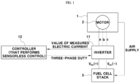
- FIG.1 is a schematic block diagram illustrating a configuration of a control device according to the present disclosure that performs an abnormality diagnosis process according to the present disclosure.
- the control device illustrated in FIG. 1 performs not only sensorless control of a motor 2 of an air compressor 1, but also a process of diagnosing the motor 2 thereof to determine whether or not the sensorless control fails.
- an abnormal state of the sensorless control means a control failure state where the sensorless control of the motor 2 of the air compressor 1 is not normally performed.
- the abnormal state of the sensorless control includes a state where the motor 2 is driven without properly performing positional alignment control of the motor 2 when the motor 2 starts.
- the motor 2 of the air compressor 1 and a fuel cell stack 3 are illustrated in FIG. 1 .
- the fuel cell stack 3 is supplied by the air compressor 1 with air that is an oxidant gas.
- the air compressor 1 serves the purpose of supplying air, necessary to generate electricity, to the fuel cell stack 3 of a fuel cell system.
- the motor 2 is hereinafter referred to as the motor 2 of the air compressor 1.
- an actual speed of the motor 2 is hereinafter described as having the same meaning as a speed of a rotor and, more particularly, as an actual rotational speed (an angular speed) of the rotor that is a rotational component among components of the motor 2.
- an actual speed of the motor 2 is measured, and the actual speed of the motor 2 is obtained from a signal of the Hall sensor.
- an actual position of the motor 2 is hereinafter described as having the same meaning as an actual rotational position of the rotor.
- an actual position of the motor 2 is measured by the Hall sensor.
- the estimated speed of the motor 2 is hereinafter described as having the meaning as a rotational speed of a magnetic field that is to be applied to a stator during a sensorless control process. That is, in a case where the motor 2 for the air compressor 1 is a synchronization motor, when the sensorless control is performed without using the Hall sensor, the rotational speed of the magnetic field that is to be applied to the stator is estimated as a speed of the motor 2, and the estimated speed of the motor 2 is used.
- the speed of the motor 2 that is estimated in this manner is different from the actual speed of the motor that is a speed measured by a sensor.
- a difference occurs between the actual speed of the motor 22(an actual rotational speed of the rotor) and the estimated speed of the motor 2 that is the rotational speed of the magnetic field that is to be applied to the stator.
- the air compressor 1 serves the purpose of supplying air that is an oxidant gas, among reactant gases for an electrochemical reaction generating electrical energy, to the fuel cell stack 3.
- the air compressor 1 is connected to a cathode terminal-side of the fuel cell stack 3 through an air supply line.
- the air compressor 1 includes the motor 2, as a drive actuator.
- the driving of the motor 2 is controlled by the control device.
- the motor 2 may be the synchronization motor.
- the control device for controlling the driving of the motor 2 includes an inverter 11 and a controller 12.
- the inverter 11 applies three-phase electric current to the motor 2.
- the controller 12 performs duty control on a three-phase switch of the inverter 11.
- the inverter 11 is connected to the fuel cell stack 3 that is a high-voltage direct current power source. When the motor 2 is driven, the inverter 11 converts direct current (DC) supplied from the fuel cell stack 3 into three-phase alternating current (AC) and applies the resulting three-phase alternating current to the motor 2 through a power cable.
- DC direct current
- AC three-phase alternating current
- the controller 12 performs the sensorless control of the motor 2.
- the controller 12 receives a value of measured electric current of the inverter 11, as an input, and estimates a position and a speed of the motor 2.
- the controller 12 outputs a three-phase duty signal for a switch within in the inverter 11 on the basis of the estimated position and speed of the motor 2 and performs the sensorless control for driving the motor 2 of the air compressor 1.
- the sensorless control here means to control the driving of the motor 2 by estimating the position, angle, and speed of the motor 2 without the Hall sensor that is a positional sensor for positional control of the motor 2.
- the actual rotational speed of the rotor is 0 rpm (the actual speed of the motor is 0 rpm)
- the rotational speed of the magnetic field (which is the estimated speed of the motor 2 when the sensorless control is performed) is divergently applied at a very high speed.
- a method of realizing and additionally performing a function of diagnosing abnormality of the sensorless control through a software logic while maintaining an existing hardware configuration of the control device without any change thereto is provided.
- FIGS. 2 to 4 are views each illustrating the speed of the motor 2 that is estimated during the sensorless control process (the estimated speed of the motor 2).
- FIGS. 2 to 4 illustrate a result of comparison of the speed of the motor 2 in a normal (success in the control) state and the speed of the motor 2 in an abnormal (failure in the control) state.
- the rotational speed of the magnetic field that is to be applied to the stator is increased faster with a greater slope than in the normal state.
- the abnormality of the sensorless control is diagnosed using this feature in a case where a slope of the estimated speed of the motor 2 is increased to a predetermined value or higher when the motor 2 is initially driven.
- a change in the slope of the estimated speed of the motor 2 is checked by decreasing the amount of electric current to be applied to the motor 2 by a predetermined value.
- the estimated speed of the motor 2 is increased as is, without the slope being changed to the predetermined level or higher, it is determined that the sensorless control is in a failed state (in the abnormal state). Then, the driving of the motor 2 is interrupted, and the positional alignment control is reperformed to attempt to restart the motor 2.
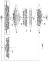
- FIG. 5 is a flowchart for an abnormality diagnosis process according to an embodiment of the present disclosure.
- the controller 12 receives a command value of the speed of the motor 2 that is higher than 0 rpm from a controller at a higher level than the controller 12 and attempts to initially start the motor 2. At this time, the controller 12 performs the function of diagnosing the abnormality of the sensorless control according to the order of steps illustrated in FIG. 5 .
- the controller 12 estimates the speed of the motor 2 in real time. In addition, from the speed of the motor 2 estimated in real time (hereinafter referred to the estimated speed of the motor 2), the controller 12 determines whether or not a condition for activating the function of diagnosing the abnormality of the sensorless control is satisfied. At this point, the condition for activating the function of diagnosing the abnormality of the sensorless control may be set to be a condition that the slope of the estimated speed of the motor 2 is at or above a preset reference value for diagnosing the abnormality of the sensorless control.
- the controller 12 checks whether or not the estimated speed of the motor 2 is increased with a slope greater than the reference value for diagnosing the abnormality of the sensorless control (S11). In a case where a slope with which the estimated speed of the motor 2 is increased is at or above the reference value for diagnosing the abnormality of the sensorless control, the controller 12 determines that the condition for activating the function of diagnosing the abnormality of the sensorless control is satisfied. Thus, the controller 12 activates the function of diagnosing the abnormality of the sensorless control (S12).
- the estimated speed of the motor 2 means the rotational speed of the magnetic field that is to be applied to the stator, as a speed of the motor 2 that is estimated during the sensorless control process.
- the Hall sensor is not used. Therefore, a position of the rotor is not measured by the Hall sensor, but the three-phase electric current to be applied to the motor 2 is measured.
- the value of the measured electric current that is, a value of the measured three-phase electric current is input into the controller 12.
- the controller 12 controlling the motor 2 of the air compressor 1 determines the rotational speed of the magnetic field that is to be applied to the stator, using a voltage equation or the like on the basis of the value of the measured electric current, the electric-current command value, and the like. Then, the controller 12 controls the driving of the motor 2 using the determined rotational speed as the estimated speed of the motor 2.
- the rotational speed of the magnetic field that is to be applied to the stator is used as the estimated speed of the motor 2.
- the rotational speed of the magnetic field that is to be applied to the stator is information that is determined by the controller 12 itself.
- the controller 12 determines in real time the rotational speed of the magnetic field that is to be applied to the stator, on the basis of the value of the measured electric or the like. Therefore, the rotational speed of the magnetic field is a value that the controller 12 always recognizes when the sensorless control is performed.
- the controller 12 performs control for decreasing the amount of the electric current to be applied to the motor 2 (S13). At this time, the controller 12 decreases the electric-current command value using a preset slope and thus may decrease the amount of electric current to be actually applied to the motor 2. In addition, while the amount of the electric current to be applied to the motor 2 is decreased, the controller 12 checks whether or not the slope of the estimated speed of the motor 2 is in proportion to a slope for the decrease in the amount of electric current.
- the rotor In a case where the rotor is actually synchronized to the rotation of the magnetic field that is to be applied to the stator and thus is rotated, the counter-electromotive force is generated. Accordingly, the amount of change in the estimated speed of the motor 2 and the slope (a change ratio) are decreased in proportion to the amount of applied electric current. However, in a case where the rotor is kept stationary and where the sensorless control fails, although the amount of electric current to be applied is decreased, the rotor is kept under no load, and thus the amount of change in the estimated speed of the motor 2 and the slope (the change ratio) are not decreased.
- the controller 12 also continues to compute the estimated speed of the motor 2 in real time. Furthermore, the controller 12 computes the slope of the estimated speed of the motor 2 and at the same time computes an amount of decrease in the slope of the estimated speed of the motor 2 in real time.
- the controller 12 compares the computed amount of the decrease in the slope of the estimated speed of the motor 2 with a preset value for confirming diagnosis of the abnormality of the sensorless control (S14). At this point, in a case where the amount of the decrease in the slope of the estimated speed of the motor 2 exceeds the value for confirming the diagnosis of the abnormality of the sensorless control, the controller 12 determines that the sensorless control is in the normal (success in the control) state. Then, the controller 12 no longer performs the function of diagnosing the abnormality of the sensorless control and then performs normal control of the driving of the motor 2 (S15).
- the controller 12 determines that the sensorless control fails and is in the abnormal state.
- the controller 12 interrupts the driving of the motor 2.
- the controller 12 reperforms the positional alignment control of the motor 2 and restarts the motor 2.
- the controller 12 may also repeatedly perform the process in FIG. 5 . Only in a case where the sensorless control is in the normal state, the controller 12 may perform the normal control of the driving of the motor 2.
- the method of diagnosing the abnormality of the sensorless control according to the present disclosure is described above.
- the sensorless control fails due to the improper performing of the positional alignment control during a process of starting the motor 2 after the positional alignment control is performed.
- a process of diagnosing the failure in the sensorless control and a subsequent action to deal with the failure in the sensorless control are not performed. Accordingly, when the sensorless control is performed, the estimated speed of the motor 2 is divergently applied, and thus it may be impossible to drive a fuel cell vehicle.
- the motor 2 immediately after started, the motor 2 is quickly diagnosed to determine whether or not the sensorless control fails, on the basis of the slope with which the estimated speed of the motor 2 is increased. Then, an attempt may be made to restart the motor 2.
- the speed command value that is transferred from the controller at a higher level than the controller 12 can be quickly received, and the motor 2 can be rapidly restarted. Thus, a quick corrective response can be taken in such a manner that the fuel cell vehicle is drivable.
- the function of diagnosing the abnormality of the sensorless control can be additionally performed in a simple manner through the software logic while maintaining the existing hardware configuration of the control device without any change thereto. Therefore, the advantage of adding a new function to the air supply device of the fuel cell system of the fuel cell vehicle can be achieved.
- a “controller” can include one or more of the following components: at least one central processing unit (CPU) configured to execute computer program instructions to perform various processes and methods, random access memory (RAM) and read only memory (ROM) configured to access and store data and information and computer program instructions, input/output (I/O) devices configured to provide input and/or output to the processing controller (e.g., keyboard, mouse, display, speakers, printers, modems, network cards, etc.), and storage media or other suitable type of memory (e.g., such as, for example, RAM, ROM, programmable read-only memory (PROM), erasable programmable read-only memory (EPROM), electrically erasable programmable read-only memory (EEPROM), magnetic disks, optical disks, floppy disks, hard disks, removable cartridges, flash drives, any type of tangible and non-transitory storage medium) where data and/or instructions can be stored.
- CPU central processing unit
- RAM random access memory
- ROM read only memory
- the controller can include antennas, network interfaces that provide wireless and/or wire line digital and/or analog interface to one or more networks over one or more network connections (not shown), a power source that provides an appropriate alternating current (AC) or direct current (DC) to power one or more components of the controller, and a bus that allows communication among the various disclosed components of the controller.
- network interfaces that provide wireless and/or wire line digital and/or analog interface to one or more networks over one or more network connections (not shown)
- a power source that provides an appropriate alternating current (AC) or direct current (DC) to power one or more components of the controller
- DC direct current
Landscapes
- Engineering & Computer Science (AREA)
- Power Engineering (AREA)
- Mechanical Engineering (AREA)
- General Engineering & Computer Science (AREA)
- Computer Hardware Design (AREA)
- Physics & Mathematics (AREA)
- General Physics & Mathematics (AREA)
- Automation & Control Theory (AREA)
- Control Of Electric Motors In General (AREA)
- Control Of Motors That Do Not Use Commutators (AREA)
Abstract
Description
- The present disclosure relates to a method of diagnosing abnormality of sensorless control of a motor for an air compressor. More particularly, the present disclosure relates to a method of diagnosing abnormality of sensorless control of a motor for an air compressor, the method being capable of quickly determining a failure in sensorless control including positional alignment control of a rotor and of interrupting control of driving of a motor when the sensorless control fails.
- A fuel cell system that is mounted in a hydrogen fuel cell vehicle that is one of environment-friendly vehicles includes a fuel cell stack, a hydrogen supply device, an air supply device, a heat and water management system, and a controller (fuel cell control unit (FCU)). The fuel cell stack generates electric energy from electrochemical reactions of reactant gases (that is, hydrogen as a fuel gas and oxygen as an oxidant gas). The hydrogen supply device supplies hydrogen that is the fuel gas, to the fuel cell stack. The air supply device supplies air containing oxygen, to the fuel cell stack. The heat and water management system control an operating temperature of the fuel cell stack and perform a water management function. The controller controls an overall operation of the fuel cell system.
- In the fuel cell system, the hydrogen supply device includes a hydrogen storage unit (a hydrogen tank), a regulator, a hydrogen supply line, a hydrogen pressure control valve (also referred to as a "hydrogen supply valve"), a hydrogen pressure sensor, a hydrogen recirculation unit, and the like. In addition, the air supply apparatus includes a filter, an air blower, an air compressor, a humidifier, and the like. The heat and water management system includes an electrically powered water pump (coolant pump), a water tank, a radiator, a 3-way valve, a water trap, a drain valve, and the like.
- In addition, the controller (fuel cell control unit (FCU)) controls the degree of opening of a hydrogen pressure valve and thus controls a hydrogen operating pressure. The fuel cell control unit controls driving of the air compressor or the air blower and controls other valves within the system.
- Recently, the performance of fuel cell vehicles has been much more improved, and thus there is a trend to increase a required output of the fuel cell stack that is a power source for the vehicle. Accordingly, there is also a trend to increase an air compression ratio and a required amount of air flow in the air compressor supplying air to the fuel cell stack. To this end, there is a need to increase a maximum speed of a motor that is driven for air compression in the air compressor.
- For positional control of the motor, the air compressor includes a Hall sensor that is a positional sensor. The Hall sensor is susceptible to heat. As a result, as a speed of the motor of the air compressor increases, an amount of heat generated in the motor increases. The increase in the speed of the
motor 2 may cause a situation wherein the use of the Hall sensor is restricted. - For this reason, instead of using the Hall sensor, there is a need to develop a technology for sensorless control. Accordingly, control devices have been developed that perform the sensorless control to drive and control the motor of the air compressor without the Hall sensor.
- Examples of Patent Documents related to the sensorless control of the motor of the air compressor include
Korean Patent Application Publication Nos. 10-2021-0041712 (April 16, 2021 10-2021-0011110 (February 1, 2021 - However, the initial position of the rotor may not be normally identified through the positional alignment control due to restraint of the rotor of the motor or due to improper application of electric current. In this state, in a case where the motor starts to be driven, the control fails, and an estimated speed of the motor is divergently applied.
- The foregoing is intended merely to aid in the understanding of the background of the present disclosure, and is not intended to mean that the present disclosure falls within the purview of the related art that is already known to those skilled in the art.
- An objective of the present disclosure is to provide a method of diagnosing abnormality of sensorless control of a motor for an air compression, the method being capable of quickly determining a failure in sensorless control and interrupting control of driving of a motor when the sensorless control fails. It is difficult to determine in advance before the motor is driven whether or not positional alignment control succeeds. An estimated speed of the motor is divergently applied in a case where the positional alignment control fails. For this reason, there is a need to quickly determine the failure in the sensorless control and to interrupt the control of the driving of the motor when the sensorless control fails.
- According to an aspect of the present disclosure, there is provided a method of diagnosing an abnormality of sensorless control of a motor for an air compressor, the method including: estimating, by a controller, a speed of a motor of an air compressor in real time and beginning when the motor starts; determining, by the controller, whether or not a preset condition for activating a function of diagnosing abnormality of sensorless control is satisfied, from a slope of the estimated speed of the motor; performing, by the controller and in a case where the preset condition is satisfied, a control operation for decreasing an amount of electric current to be applied to the motor; computing, by the controller and in a case where the control operation for decreasing an amount of electric current is performed, an amount of decrease in the slope of the speed of the motor, the speed being estimated in real time; and determining, by the controller, whether or not the sensorless control fails by comparing the amount of the decrease in the slope of the speed of the motor against a preset value for confirming diagnosis of the abnormality of the sensorless control.
- Accordingly, with the method of diagnosing abnormality of sensorless control of a motor for an air compressor, immediately after the motor starts, it can be diagnosed, on the basis of the slope with which the estimated speed of the motor is increased, whether or not the sensorless control fails. Then, an attempt can be made to restart the motor. In addition, a speed command value that is transferred from a controller at a higher level than the controller can be quickly received, and the motor can be rapidly restarted. Thus, a quick corrective response can be taken in such a manner that a fuel cell vehicle is drivable.
- In addition, according to the present disclosure, the function of diagnosing the abnormality of the sensorless control can be additionally performed in a simple manner through a software logic while maintaining an existing hardware configuration of a control device without any change thereto. Therefore, the advantage of adding a new function to an air supply device of a fuel cell system of the fuel cell vehicle can be achieved.
- In additional embodiments, the preset condition for activating the function of diagnosing the abnormality of the sensorless control is set to be a condition that the slope of the estimated speed of the motor is at or above a preset reference value for diagnosing the abnormality of the sensorless control.
- In additional embodiments, the performing of the control operation for decreasing the amount of the electric current to be applied to the motor step further includes: decreasing, by the controller, an electric-current command value by using a preset slope thereby decreasing an amount of electric current applied to the motor through an inverter based on the electric-current command value.
- In additional embodiments, the determining whether or not the sensorless control fails step further includes: determining if the amount of the decrease in the slope of the speed of the motor is less than or equal to the preset value for confirming the diagnosis of the abnormality of the sensorless control. In some embodiments, if the speed of the motor is less than or equal to the preset value the controller determines that the sensorless control is in a failed state.
- In additional embodiments, if it is determined that the sensorless control is in a failed state, the controller further performs the steps of: interrupting driving of the motor; reperforming positional alignment control of the motor; and restarting of the motor.
- In additional embodiments, when restarting of the motor is performed, the controller: repeatedly performs the estimating of the speed of the motor in real time; repeatedly performs the determining of whether or not the condition of activating the function of diagnosing the abnormality of the sensorless control in real time; repeatedly performs the performing of the control for decreasing the amount of the electric current to be applied to the motor in real time; repeatedly performs the computing of the amount of the decrease in the slope of the speed of the motor in real time, and repeatedly performs the determining of whether or not the sensorless control fails. In some embodiments, in a case where it is determined by the controller that the sensorless control is in a normal state, a normal control of the driving of the motor is performed.
- In various embodiments, in a case where the amount of the decrease in the slope of the speed of the motor exceeds the preset value for confirming the diagnosis of the abnormality of the sensorless control, the controller determines that the sensorless control is in a normal state and performs normal control of the driving of the motor.
- The above and other objectives, features, and other advantages of the present disclosure will be more clearly understood from the following detailed description when taken in conjunction with the accompanying drawings, in which:
-
FIG. 1 is a schematic block diagram illustrating a configuration of a control device according to the present disclosure that performs an abnormality diagnosis process according to the present disclosure; -
FIG. 2 is a first view illustrating a speed of a motor that is estimated during a sensorless control process according to the present disclosure; -
FIG. 3 is a second view illustrating a speed of a motor that is estimated during a sensorless control process according to the present disclosure; -
FIG. 4 is a third view illustrating a speed of a motor that is estimated during a sensorless control process according to the present disclosure; and -
FIG. 5 is a flowchart for an abnormality diagnosis process according to an embodiment of the present disclosure. - Embodiments of the present disclosure will be described below with reference to the illustrations in terms of specific structures and functions. Various embodiments are conceivable without departing from the nature and gist of the present disclosure. The present disclosure should not be construed as being limited to embodiments described in the present specification. All alterations, equivalents, and substitutes that are included within the technical idea of the present disclosure should be understood as falling within the scope of the present disclosure.
- In the present specification, the terms first, second, and so on are used to describe various constituent elements, but these elements are not limited to those terms. Those terms are only used to distinguish one constituent element from another. For instance, a first constituent element may be termed a second constituent element without departing from the scope of each claim that defines the present disclosure. Likewise, the second constituent element may also be termed the first constituent element.
- It should be understood that a constituent element, when referred to as being "coupled to" or "connected to" a different constituent element, may be directly coupled to or directly connected to the different constituent element or may be coupled to or connected to the different constituent element with an intervening constituent element being interposed therebetween. In contrast, it should be understood that a constituent element, when referred to as being "directly coupled to" or "directly connected to" a different constituent element, is coupled to or connected to the different constituent without any intervening constituent element being interposed therebetween. Expressions such as "between" and "directly between" and expressions "adjacent to" and "directly adjacent to" that are used for describing a relationship between constituent elements should be construed in the same manner.
- Like reference numerals depict like constituent elements throughout the present specification. The terms used throughout the present specification serve the purpose of describing embodiments and do not impose any limitation on the present disclosure. Unless specified otherwise through the present specification, a singular noun or a singular noun phrase may have a plural meaning. The terms "comprise" and/or "comprising" are intended to indicate that named constituent elements, steps, operations, and/or elements are present, without precluding the presence or addition of one or more other constituent elements, steps, operations, and/or elements.
- Embodiments of the present disclosure will be described below with reference to the accompanying drawings.
-
FIG.1 is a schematic block diagram illustrating a configuration of a control device according to the present disclosure that performs an abnormality diagnosis process according to the present disclosure. The control device illustrated inFIG. 1 performs not only sensorless control of amotor 2 of an air compressor 1, but also a process of diagnosing themotor 2 thereof to determine whether or not the sensorless control fails. - According to the present disclosure, an abnormal state of the sensorless control means a control failure state where the sensorless control of the
motor 2 of the air compressor 1 is not normally performed. In addition, according to the present disclosure, the abnormal state of the sensorless control includes a state where themotor 2 is driven without properly performing positional alignment control of themotor 2 when themotor 2 starts. - Along with the control device, the
motor 2 of the air compressor 1 and afuel cell stack 3 are illustrated inFIG. 1 . Thefuel cell stack 3 is supplied by the air compressor 1 with air that is an oxidant gas. The air compressor 1 serves the purpose of supplying air, necessary to generate electricity, to thefuel cell stack 3 of a fuel cell system. Themotor 2 is hereinafter referred to as themotor 2 of the air compressor 1. - In addition, an actual speed of the
motor 2 is hereinafter described as having the same meaning as a speed of a rotor and, more particularly, as an actual rotational speed (an angular speed) of the rotor that is a rotational component among components of themotor 2. Instead of when the sensorless control is performed, when control is performed using a Hall sensor, the actual speed of themotor 2 is measured, and the actual speed of themotor 2 is obtained from a signal of the Hall sensor. In addition, an actual position of themotor 2 is hereinafter described as having the same meaning as an actual rotational position of the rotor. Instead of when the sensorless control is performed, when the control is performed using the Hall sensor, an actual position of themotor 2 is measured by the Hall sensor. - However, a system in which the sensorless control is performed is not equipped with the Hall sensor. Therefore, when driving of the
motor 2 is controlled, the estimated speed of themotor 2 is used instead of the actual speed of themotor 2. The estimated speed of themotor 2 is hereinafter described as having the meaning as a rotational speed of a magnetic field that is to be applied to a stator during a sensorless control process. That is, in a case where themotor 2 for the air compressor 1 is a synchronization motor, when the sensorless control is performed without using the Hall sensor, the rotational speed of the magnetic field that is to be applied to the stator is estimated as a speed of themotor 2, and the estimated speed of themotor 2 is used. - The speed of the
motor 2 that is estimated in this manner, that is, the estimated speed of themotor 2, is different from the actual speed of the motor that is a speed measured by a sensor. As described below, in a state where the sensorless control of the synchronization motor fails, a difference occurs between the actual speed of the motor 22(an actual rotational speed of the rotor) and the estimated speed of themotor 2 that is the rotational speed of the magnetic field that is to be applied to the stator. - In an air supply device of the fuel cell system, the air compressor 1 serves the purpose of supplying air that is an oxidant gas, among reactant gases for an electrochemical reaction generating electrical energy, to the
fuel cell stack 3. The air compressor 1 is connected to a cathode terminal-side of thefuel cell stack 3 through an air supply line. - The air compressor 1 includes the
motor 2, as a drive actuator. The driving of themotor 2 is controlled by the control device. Themotor 2 may be the synchronization motor. The control device for controlling the driving of themotor 2 includes aninverter 11 and acontroller 12. Theinverter 11 applies three-phase electric current to themotor 2. Thecontroller 12 performs duty control on a three-phase switch of theinverter 11. - The
inverter 11 is connected to thefuel cell stack 3 that is a high-voltage direct current power source. When themotor 2 is driven, theinverter 11 converts direct current (DC) supplied from thefuel cell stack 3 into three-phase alternating current (AC) and applies the resulting three-phase alternating current to themotor 2 through a power cable. - The
controller 12 performs the sensorless control of themotor 2. For the sensorless control, thecontroller 12 receives a value of measured electric current of theinverter 11, as an input, and estimates a position and a speed of themotor 2. In addition, thecontroller 12 outputs a three-phase duty signal for a switch within in theinverter 11 on the basis of the estimated position and speed of themotor 2 and performs the sensorless control for driving themotor 2 of the air compressor 1. The sensorless control here means to control the driving of themotor 2 by estimating the position, angle, and speed of themotor 2 without the Hall sensor that is a positional sensor for positional control of themotor 2. - With a known sensorless control method for the
motor 2 of the air compressor 1, positional alignment control of themotor 2 of the air compressor 1 is performed, and thus an initial position of the rotor is identified. Then, themotor 2 starts to be driven. However, the initial position of the rotor may not be normally identified through the positional alignment control due to restraint of the rotor of themotor 2 or due to improper application of electric current. In this state, in a case where themotor 2 starts to be driven, rotation of the rotor (rotation of the motor 2) is actually not synchronized to rotation of the magnetic field, and thus the rotor is kept stationary. Accordingly, a counter-electromotive force is not generated, and thus electric current is applied without load on the rotor. Therefore, the rotational speed (the angular speed) of the magnetic field that is to be applied to the stator is divergently applied at a very high speed. - In short, the actual rotational speed of the rotor is 0 rpm (the actual speed of the motor is 0 rpm), the rotational speed of the magnetic field (which is the estimated speed of the
motor 2 when the sensorless control is performed) is divergently applied at a very high speed. - Therefore, in order to solve the above-described problem, according to the present disclosure, a method of realizing and additionally performing a function of diagnosing abnormality of the sensorless control through a software logic while maintaining an existing hardware configuration of the control device without any change thereto.
-
FIGS. 2 to 4 are views each illustrating the speed of themotor 2 that is estimated during the sensorless control process (the estimated speed of the motor 2).FIGS. 2 to 4 illustrate a result of comparison of the speed of themotor 2 in a normal (success in the control) state and the speed of themotor 2 in an abnormal (failure in the control) state. As illustrated, when themotor 2 starts initially, in a case where themotor 2 starts to be driven without the positional alignment control of the rotor being normally performed, the rotational speed of the magnetic field that is to be applied to the stator (the estimated speed of the motor 2) is increased faster with a greater slope than in the normal state. - The reason for this is because the rotor remains stationary without being synchronized to the stator and because electric current is thus applied to the rotor without load thereon. This application increases the estimated speed of the
motor 2, which is the rotational speed of the magnetic field that is to be applied to the stator, much more than in the normal state. - When the
motor 2 starts initially, it can be seen fromFIG. 2 that the estimated speed of themotor 2 is increased with a steeper slope in a case where the sensorless control fails than in a case where the sensorless control succeeds normally. - In addition, in a case where normal sensorless control is performed and where the
motor 2 is in a driven state, when the estimated speed of themotor 2 almost reaches a speed command value, as illustrated inFIG. 3 , an amount of electric current to be applied is decreased, and thus the estimated speed of themotor 2 naturally converges to the speed command value. However, in a case where the sensorless control fails, as illustrated inFIG. 4 , although the amount of electric current to be applied is decreased, the estimated speed of themotor 2 is divergently applied as is. - In the case where the normal sensorless control is performed and where the
motor 2 is in the driven state, it can be seen fromFIG. 3 that at the same time as an electric-current command value is increased, an amount of change in the estimated speed of themotor 2 is also decreased. However, when the sensorless control fails, although the electric-current command value is decreased, the estimated speed of themotor 2 is divergently applied as is. - According to the present disclosure, the abnormality of the sensorless control is diagnosed using this feature in a case where a slope of the estimated speed of the
motor 2 is increased to a predetermined value or higher when themotor 2 is initially driven. In addition, in a case where the abnormality of the sensorless control is diagnosed, a change in the slope of the estimated speed of themotor 2 is checked by decreasing the amount of electric current to be applied to themotor 2 by a predetermined value. At this point, in a case where the estimated speed of themotor 2 is increased as is, without the slope being changed to the predetermined level or higher, it is determined that the sensorless control is in a failed state (in the abnormal state). Then, the driving of themotor 2 is interrupted, and the positional alignment control is reperformed to attempt to restart themotor 2. - Conversely, in a case where a value of the slope with which the estimated speed of the
motor 2 is increased is decreased to a predetermined value or higher when the amount of electric current to be applied is decreased, it is determined that the sensorless control is in the normal state (succeeds). Thus, the function of diagnosing the abnormality of the sensorless control is no longer performed, and the normal sensorless control and the motor driving are maintained. -
FIG. 5 is a flowchart for an abnormality diagnosis process according to an embodiment of the present disclosure. - The
controller 12 receives a command value of the speed of themotor 2 that is higher than 0 rpm from a controller at a higher level than thecontroller 12 and attempts to initially start themotor 2. At this time, thecontroller 12 performs the function of diagnosing the abnormality of the sensorless control according to the order of steps illustrated inFIG. 5 . - First, when initially starting the
motor 2, thecontroller 12 estimates the speed of themotor 2 in real time. In addition, from the speed of themotor 2 estimated in real time (hereinafter referred to the estimated speed of the motor 2), thecontroller 12 determines whether or not a condition for activating the function of diagnosing the abnormality of the sensorless control is satisfied. At this point, the condition for activating the function of diagnosing the abnormality of the sensorless control may be set to be a condition that the slope of the estimated speed of themotor 2 is at or above a preset reference value for diagnosing the abnormality of the sensorless control. - That is, the
controller 12 checks whether or not the estimated speed of themotor 2 is increased with a slope greater than the reference value for diagnosing the abnormality of the sensorless control (S11). In a case where a slope with which the estimated speed of themotor 2 is increased is at or above the reference value for diagnosing the abnormality of the sensorless control, thecontroller 12 determines that the condition for activating the function of diagnosing the abnormality of the sensorless control is satisfied. Thus, thecontroller 12 activates the function of diagnosing the abnormality of the sensorless control (S12). - The estimated speed of the
motor 2 means the rotational speed of the magnetic field that is to be applied to the stator, as a speed of themotor 2 that is estimated during the sensorless control process. When the sensorless control is performed, the Hall sensor is not used. Therefore, a position of the rotor is not measured by the Hall sensor, but the three-phase electric current to be applied to themotor 2 is measured. The value of the measured electric current, that is, a value of the measured three-phase electric current is input into thecontroller 12. - In addition, the
controller 12 controlling themotor 2 of the air compressor 1 determines the rotational speed of the magnetic field that is to be applied to the stator, using a voltage equation or the like on the basis of the value of the measured electric current, the electric-current command value, and the like. Then, thecontroller 12 controls the driving of themotor 2 using the determined rotational speed as the estimated speed of themotor 2. - In this manner, when the sensorless control is performed, the rotational speed of the magnetic field that is to be applied to the stator is used as the estimated speed of the
motor 2. The rotational speed of the magnetic field that is to be applied to the stator is information that is determined by thecontroller 12 itself. In addition, thecontroller 12 determines in real time the rotational speed of the magnetic field that is to be applied to the stator, on the basis of the value of the measured electric or the like. Therefore, the rotational speed of the magnetic field is a value that thecontroller 12 always recognizes when the sensorless control is performed. - Subsequently, when the function of diagnosing the abnormality of the sensorless control is activated, through the
inverter 11, thecontroller 12 performs control for decreasing the amount of the electric current to be applied to the motor 2 (S13). At this time, thecontroller 12 decreases the electric-current command value using a preset slope and thus may decrease the amount of electric current to be actually applied to themotor 2. In addition, while the amount of the electric current to be applied to themotor 2 is decreased, thecontroller 12 checks whether or not the slope of the estimated speed of themotor 2 is in proportion to a slope for the decrease in the amount of electric current. - In a case where the rotor is actually synchronized to the rotation of the magnetic field that is to be applied to the stator and thus is rotated, the counter-electromotive force is generated. Accordingly, the amount of change in the estimated speed of the
motor 2 and the slope (a change ratio) are decreased in proportion to the amount of applied electric current. However, in a case where the rotor is kept stationary and where the sensorless control fails, although the amount of electric current to be applied is decreased, the rotor is kept under no load, and thus the amount of change in the estimated speed of themotor 2 and the slope (the change ratio) are not decreased. - As described above, while the amount of the electric current to be applied to the
motor 2 is decreased, thecontroller 12 also continues to compute the estimated speed of themotor 2 in real time. Furthermore, thecontroller 12 computes the slope of the estimated speed of themotor 2 and at the same time computes an amount of decrease in the slope of the estimated speed of themotor 2 in real time. - In addition, the
controller 12 compares the computed amount of the decrease in the slope of the estimated speed of themotor 2 with a preset value for confirming diagnosis of the abnormality of the sensorless control (S14). At this point, in a case where the amount of the decrease in the slope of the estimated speed of themotor 2 exceeds the value for confirming the diagnosis of the abnormality of the sensorless control, thecontroller 12 determines that the sensorless control is in the normal (success in the control) state. Then, thecontroller 12 no longer performs the function of diagnosing the abnormality of the sensorless control and then performs normal control of the driving of the motor 2 (S15). - By contrast, in a case where the amount of the decrease in the slope of the estimated speed of the
motor 2 is at or below the value for confirming the diagnosis of the abnormality of the sensorless control, thecontroller 12 determines that the sensorless control fails and is in the abnormal state. When it is determined that the sensorless control is in the abnormal state, thecontroller 12 interrupts the driving of themotor 2. Then, thecontroller 12 reperforms the positional alignment control of themotor 2 and restarts themotor 2. During the process of restarting themotor 2, thecontroller 12 may also repeatedly perform the process inFIG. 5 . Only in a case where the sensorless control is in the normal state, thecontroller 12 may perform the normal control of the driving of themotor 2. - The method of diagnosing the abnormality of the sensorless control according to the present disclosure is described above. In the related art, the sensorless control fails due to the improper performing of the positional alignment control during a process of starting the
motor 2 after the positional alignment control is performed. However, in the related art, a process of diagnosing the failure in the sensorless control and a subsequent action to deal with the failure in the sensorless control are not performed. Accordingly, when the sensorless control is performed, the estimated speed of themotor 2 is divergently applied, and thus it may be impossible to drive a fuel cell vehicle. - However, with a method of diagnosing the abnormality of the sensorless control of the
motor 2 according to the present disclosure, immediately after started, themotor 2 is quickly diagnosed to determine whether or not the sensorless control fails, on the basis of the slope with which the estimated speed of themotor 2 is increased. Then, an attempt may be made to restart themotor 2. In addition, the speed command value that is transferred from the controller at a higher level than thecontroller 12 can be quickly received, and themotor 2 can be rapidly restarted. Thus, a quick corrective response can be taken in such a manner that the fuel cell vehicle is drivable. - In addition, according to the present disclosure, the function of diagnosing the abnormality of the sensorless control can be additionally performed in a simple manner through the software logic while maintaining the existing hardware configuration of the control device without any change thereto. Therefore, the advantage of adding a new function to the air supply device of the fuel cell system of the fuel cell vehicle can be achieved.
- The embodiments of the present disclosure are described in detail above, but impose no limitation on the claimed scope of the present disclosure. Various modifications and improvements that a person of ordinary skill in the art makes using the fundamental concept of the present disclosure that is defined in the following claims are also included in the claimed scope of the present disclosure.
- In some implementations, a "controller" can include one or more of the following components: at least one central processing unit (CPU) configured to execute computer program instructions to perform various processes and methods, random access memory (RAM) and read only memory (ROM) configured to access and store data and information and computer program instructions, input/output (I/O) devices configured to provide input and/or output to the processing controller (e.g., keyboard, mouse, display, speakers, printers, modems, network cards, etc.), and storage media or other suitable type of memory (e.g., such as, for example, RAM, ROM, programmable read-only memory (PROM), erasable programmable read-only memory (EPROM), electrically erasable programmable read-only memory (EEPROM), magnetic disks, optical disks, floppy disks, hard disks, removable cartridges, flash drives, any type of tangible and non-transitory storage medium) where data and/or instructions can be stored. In addition, the controller can include antennas, network interfaces that provide wireless and/or wire line digital and/or analog interface to one or more networks over one or more network connections (not shown), a power source that provides an appropriate alternating current (AC) or direct current (DC) to power one or more components of the controller, and a bus that allows communication among the various disclosed components of the controller.
Claims (9)
- A method of diagnosing an abnormality of sensorless control of a motor for an air compressor, the method comprising:estimating, by a controller, a speed of a motor of an air compressor in real time and beginning when the motor starts;determining, by the controller, whether or not a preset condition for activating a function of diagnosing abnormality of sensorless control is satisfied, from a slope of the estimated speed of the motor;performing, by the controller and in a case where the preset condition is satisfied, a control operation for decreasing an amount of electric current to be applied to the motor;computing, by the controller and in a case where the control operation for decreasing an amount of electric current is performed, an amount of decrease in the slope of the speed of the motor, the speed being estimated in real time; anddetermining, by the controller, whether or not the sensorless control fails by comparing the amount of the decrease in the slope of the speed of the motor against a preset value for confirming diagnosis of the abnormality of the sensorless control.
- The method of claim 1, wherein the preset condition for activating the function of diagnosing the abnormality of the sensorless control is set to be a condition that the slope of the estimated speed of the motor is at or above a preset reference value for diagnosing the abnormality of the sensorless control.
- The method of claim 1, wherein the performing of the control operation for decreasing the amount of the electric current to be applied to the motor step further comprises:
decreasing, by the controller, an electric-current command value by using a preset slope thereby decreasing an amount of electric current applied to the motor through an inverter based on the electric-current command value. - The method of claim 1, wherein the determining whether or not the sensorless control fails step further comprises:
determining if the amount of the decrease in the slope of the speed of the motor is less than or equal to the preset value for confirming the diagnosis of the abnormality of the sensorless control, wherein if the speed of the motor is less than or equal to the preset value the controller determines that the sensorless control is in a failed state. - The method of claim 1, wherein if it is determined that the sensorless control is in a failed state, the controller further performs the steps of:interrupting driving of the motor;reperforming positional alignment control of the motor; andrestarting of the motor.
- The method of claim 5, wherein when restarting of the motor is performed, the controller:repeatedly performs the estimating of the speed of the motor in real time;repeatedly performs the determining of whether or not the condition of activating the function of diagnosing the abnormality of the sensorless control in real time;repeatedly performs the performing of the control for decreasing the amount of the electric current to be applied to the motor in real time;repeatedly performs the computing of the amount of the decrease in the slope of the speed of the motor in real time, andrepeatedly performs the determining of whether or not the sensorless control fails; andwherein in a case where it is determined by the controller that the sensorless control is in a normal state, a normal control of the driving of the motor is performed.
- The method according to claim 4, wherein in a case where the amount of the decrease in the slope of the speed of the motor exceeds the preset value for confirming the diagnosis of the abnormality of the sensorless control, the controller determines that the sensorless control is in a normal state and performs normal control of the driving of the motor.
- The method of claim 4, wherein if it is determined that the sensorless control is in the failed state, the controller further performs the steps of:interrupting driving of the motor;reperforming positional alignment control of the motor; andrestarting of the motor.
- The method of claim 8, wherein when restarting of the motor is performed, the controller:repeatedly performs the estimating of the speed of the motor in real time;repeatedly performs the determining of whether or not the condition of activating the function of diagnosing the abnormality of the sensorless control in real time;repeatedly performs the performing of the control for decreasing the amount of the electric current to be applied to the motor in real time;repeatedly performs the computing of the amount of the decrease in the slope of the speed of the motor in real time, andrepeatedly performs the determining of whether or not the sensorless control fails; andwherein in a case where it is determined by the controller that the sensorless control is in a normal state, a normal control of the driving of the motor is performed.
Applications Claiming Priority (1)
| Application Number | Priority Date | Filing Date | Title |
|---|---|---|---|
| KR1020210140647A KR20230056874A (en) | 2021-10-21 | 2021-10-21 | Fault diagnosis method for motor sensorless control of air compressor |
Publications (2)
| Publication Number | Publication Date |
|---|---|
| EP4170447A1 true EP4170447A1 (en) | 2023-04-26 |
| EP4170447B1 EP4170447B1 (en) | 2024-05-29 |
Family
ID=83902969
Family Applications (1)
| Application Number | Title | Priority Date | Filing Date |
|---|---|---|---|
| EP22202252.7A Active EP4170447B1 (en) | 2021-10-21 | 2022-10-18 | Method of diagnosing abnormality of sensorless control of motor for air compressor |
Country Status (4)
| Country | Link |
|---|---|
| US (1) | US12215683B2 (en) |
| EP (1) | EP4170447B1 (en) |
| KR (1) | KR20230056874A (en) |
| CN (1) | CN116015162A (en) |
Citations (3)
| Publication number | Priority date | Publication date | Assignee | Title |
|---|---|---|---|---|
| US20200144643A1 (en) * | 2018-11-01 | 2020-05-07 | Hyundai Motor Company | System and method of controlling air compressor motor for fuel cell vehicle and system and method of controlling operation of fuel cell vehicle using same |
| KR20210011110A (en) | 2019-07-22 | 2021-02-01 | 현대자동차주식회사 | Control method for sensorless motor of air compressor |
| KR20210041712A (en) | 2019-10-08 | 2021-04-16 | 현대자동차주식회사 | Control method for sensorless motor of air compressor |
Family Cites Families (3)
| Publication number | Priority date | Publication date | Assignee | Title |
|---|---|---|---|---|
| US7091685B2 (en) * | 2004-01-22 | 2006-08-15 | Siemens Vdo Automotive Inc. | Overload protection for DC motors |
| KR100645808B1 (en) * | 2004-12-08 | 2006-11-23 | 엘지전자 주식회사 | Motor control method |
| KR100657489B1 (en) * | 2005-03-08 | 2006-12-19 | 엘지전자 주식회사 | Method and device for starting determination of motor without sensor |
-
2021
- 2021-10-21 KR KR1020210140647A patent/KR20230056874A/en active Pending
-
2022
- 2022-10-05 US US17/960,306 patent/US12215683B2/en active Active
- 2022-10-18 EP EP22202252.7A patent/EP4170447B1/en active Active
- 2022-10-21 CN CN202211295467.4A patent/CN116015162A/en active Pending
Patent Citations (3)
| Publication number | Priority date | Publication date | Assignee | Title |
|---|---|---|---|---|
| US20200144643A1 (en) * | 2018-11-01 | 2020-05-07 | Hyundai Motor Company | System and method of controlling air compressor motor for fuel cell vehicle and system and method of controlling operation of fuel cell vehicle using same |
| KR20210011110A (en) | 2019-07-22 | 2021-02-01 | 현대자동차주식회사 | Control method for sensorless motor of air compressor |
| KR20210041712A (en) | 2019-10-08 | 2021-04-16 | 현대자동차주식회사 | Control method for sensorless motor of air compressor |
Also Published As
| Publication number | Publication date |
|---|---|
| CN116015162A (en) | 2023-04-25 |
| KR20230056874A (en) | 2023-04-28 |
| US12215683B2 (en) | 2025-02-04 |
| EP4170447B1 (en) | 2024-05-29 |
| US20230131865A1 (en) | 2023-04-27 |
Similar Documents
| Publication | Publication Date | Title |
|---|---|---|
| JP2780074B2 (en) | Fuel cell vehicle and method for starting the same | |
| CN112397748B (en) | Fuel cell system starting control method and device | |
| US9831515B2 (en) | System and method for recovering output of fuel cell | |
| CN106876750B (en) | Control method of cooling water pump of fuel cell vehicle | |
| US11463035B2 (en) | Control method for sensorless motor | |
| US11097636B2 (en) | Fuel cell vehicle | |
| WO2005086268A1 (en) | Cooling device for fuel cell and cooling method | |
| CN112519532B (en) | Heat pump system diagnosis control method and device | |
| JP2004152729A (en) | Fuel cell system | |
| US20180026284A1 (en) | Fuel cell system | |
| JP3893929B2 (en) | Fuel cell cooling device and control method of fuel cell cooling device | |
| KR20190108238A (en) | Stop control method for fuelcell system | |
| JP6364043B2 (en) | Fuel cell system | |
| EP4170447B1 (en) | Method of diagnosing abnormality of sensorless control of motor for air compressor | |
| CN112297953A (en) | Control method and system for vehicle fuel cell | |
| CN117747874A (en) | Abnormality processing method and system for hydrogen circulating pump and electronic equipment | |
| CN115199543A (en) | Air compressor rotor locked-rotor processing method and device | |
| CN102089916A (en) | fuel cell system | |
| KR102881976B1 (en) | Method for controlling start-stop of parallel type fuel cell system | |
| US20150086891A1 (en) | Apparatus and method for starting fuel cell vehicle in emergency | |
| CN114928272A (en) | Frequency converter runaway starting method and frequency converter thereof | |
| JP2006269196A (en) | Fuel cell system | |
| JP2007059348A (en) | Fuel cell system and method for starting fuel cell system | |
| KR20120045926A (en) | Method for controlling emergency driving for fuel cell vehicle | |
| KR20210041712A (en) | Control method for sensorless motor of air compressor |
Legal Events
| Date | Code | Title | Description |
|---|---|---|---|
| PUAI | Public reference made under article 153(3) epc to a published international application that has entered the european phase |
Free format text: ORIGINAL CODE: 0009012 |
|
| STAA | Information on the status of an ep patent application or granted ep patent |
Free format text: STATUS: THE APPLICATION HAS BEEN PUBLISHED |
|
| AK | Designated contracting states |
Kind code of ref document: A1 Designated state(s): AL AT BE BG CH CY CZ DE DK EE ES FI FR GB GR HR HU IE IS IT LI LT LU LV MC ME MK MT NL NO PL PT RO RS SE SI SK SM TR |
|
| P01 | Opt-out of the competence of the unified patent court (upc) registered |
Effective date: 20230511 |
|
| STAA | Information on the status of an ep patent application or granted ep patent |
Free format text: STATUS: REQUEST FOR EXAMINATION WAS MADE |
|
| 17P | Request for examination filed |
Effective date: 20231026 |
|
| RBV | Designated contracting states (corrected) |
Designated state(s): AL AT BE BG CH CY CZ DE DK EE ES FI FR GB GR HR HU IE IS IT LI LT LU LV MC ME MK MT NL NO PL PT RO RS SE SI SK SM TR |
|
| GRAP | Despatch of communication of intention to grant a patent |
Free format text: ORIGINAL CODE: EPIDOSNIGR1 |
|
| STAA | Information on the status of an ep patent application or granted ep patent |
Free format text: STATUS: GRANT OF PATENT IS INTENDED |
|
| INTG | Intention to grant announced |
Effective date: 20240228 |
|
| GRAS | Grant fee paid |
Free format text: ORIGINAL CODE: EPIDOSNIGR3 |
|
| GRAA | (expected) grant |
Free format text: ORIGINAL CODE: 0009210 |
|
| STAA | Information on the status of an ep patent application or granted ep patent |
Free format text: STATUS: THE PATENT HAS BEEN GRANTED |
|
| AK | Designated contracting states |
Kind code of ref document: B1 Designated state(s): AL AT BE BG CH CY CZ DE DK EE ES FI FR GB GR HR HU IE IS IT LI LT LU LV MC ME MK MT NL NO PL PT RO RS SE SI SK SM TR |
|
| REG | Reference to a national code |
Ref country code: CH Ref legal event code: EP |
|
| REG | Reference to a national code |
Ref country code: IE Ref legal event code: FG4D |
|
| REG | Reference to a national code |
Ref country code: DE Ref legal event code: R096 Ref document number: 602022003685 Country of ref document: DE |
|
| REG | Reference to a national code |
Ref country code: LT Ref legal event code: MG9D |
|
| REG | Reference to a national code |
Ref country code: NL Ref legal event code: MP Effective date: 20240529 |
|
| PG25 | Lapsed in a contracting state [announced via postgrant information from national office to epo] |
Ref country code: IS Free format text: LAPSE BECAUSE OF FAILURE TO SUBMIT A TRANSLATION OF THE DESCRIPTION OR TO PAY THE FEE WITHIN THE PRESCRIBED TIME-LIMIT Effective date: 20240929 |
|
| PG25 | Lapsed in a contracting state [announced via postgrant information from national office to epo] |
Ref country code: BG Free format text: LAPSE BECAUSE OF FAILURE TO SUBMIT A TRANSLATION OF THE DESCRIPTION OR TO PAY THE FEE WITHIN THE PRESCRIBED TIME-LIMIT Effective date: 20240529 |
|
| PG25 | Lapsed in a contracting state [announced via postgrant information from national office to epo] |
Ref country code: HR Free format text: LAPSE BECAUSE OF FAILURE TO SUBMIT A TRANSLATION OF THE DESCRIPTION OR TO PAY THE FEE WITHIN THE PRESCRIBED TIME-LIMIT Effective date: 20240529 Ref country code: FI Free format text: LAPSE BECAUSE OF FAILURE TO SUBMIT A TRANSLATION OF THE DESCRIPTION OR TO PAY THE FEE WITHIN THE PRESCRIBED TIME-LIMIT Effective date: 20240529 |
|
| PG25 | Lapsed in a contracting state [announced via postgrant information from national office to epo] |
Ref country code: GR Free format text: LAPSE BECAUSE OF FAILURE TO SUBMIT A TRANSLATION OF THE DESCRIPTION OR TO PAY THE FEE WITHIN THE PRESCRIBED TIME-LIMIT Effective date: 20240830 |
|
| REG | Reference to a national code |
Ref country code: AT Ref legal event code: MK05 Ref document number: 1691160 Country of ref document: AT Kind code of ref document: T Effective date: 20240529 |
|
| PG25 | Lapsed in a contracting state [announced via postgrant information from national office to epo] |
Ref country code: ES Free format text: LAPSE BECAUSE OF FAILURE TO SUBMIT A TRANSLATION OF THE DESCRIPTION OR TO PAY THE FEE WITHIN THE PRESCRIBED TIME-LIMIT Effective date: 20240529 |
|
| PG25 | Lapsed in a contracting state [announced via postgrant information from national office to epo] |
Ref country code: AT Free format text: LAPSE BECAUSE OF FAILURE TO SUBMIT A TRANSLATION OF THE DESCRIPTION OR TO PAY THE FEE WITHIN THE PRESCRIBED TIME-LIMIT Effective date: 20240529 |
|
| PG25 | Lapsed in a contracting state [announced via postgrant information from national office to epo] |
Ref country code: PL Free format text: LAPSE BECAUSE OF FAILURE TO SUBMIT A TRANSLATION OF THE DESCRIPTION OR TO PAY THE FEE WITHIN THE PRESCRIBED TIME-LIMIT Effective date: 20240529 |
|
| PG25 | Lapsed in a contracting state [announced via postgrant information from national office to epo] |
Ref country code: LV Free format text: LAPSE BECAUSE OF FAILURE TO SUBMIT A TRANSLATION OF THE DESCRIPTION OR TO PAY THE FEE WITHIN THE PRESCRIBED TIME-LIMIT Effective date: 20240529 |
|
| PG25 | Lapsed in a contracting state [announced via postgrant information from national office to epo] |
Ref country code: PL Free format text: LAPSE BECAUSE OF FAILURE TO SUBMIT A TRANSLATION OF THE DESCRIPTION OR TO PAY THE FEE WITHIN THE PRESCRIBED TIME-LIMIT Effective date: 20240529 Ref country code: NO Free format text: LAPSE BECAUSE OF FAILURE TO SUBMIT A TRANSLATION OF THE DESCRIPTION OR TO PAY THE FEE WITHIN THE PRESCRIBED TIME-LIMIT Effective date: 20240829 Ref country code: LV Free format text: LAPSE BECAUSE OF FAILURE TO SUBMIT A TRANSLATION OF THE DESCRIPTION OR TO PAY THE FEE WITHIN THE PRESCRIBED TIME-LIMIT Effective date: 20240529 Ref country code: IS Free format text: LAPSE BECAUSE OF FAILURE TO SUBMIT A TRANSLATION OF THE DESCRIPTION OR TO PAY THE FEE WITHIN THE PRESCRIBED TIME-LIMIT Effective date: 20240929 Ref country code: HR Free format text: LAPSE BECAUSE OF FAILURE TO SUBMIT A TRANSLATION OF THE DESCRIPTION OR TO PAY THE FEE WITHIN THE PRESCRIBED TIME-LIMIT Effective date: 20240529 Ref country code: GR Free format text: LAPSE BECAUSE OF FAILURE TO SUBMIT A TRANSLATION OF THE DESCRIPTION OR TO PAY THE FEE WITHIN THE PRESCRIBED TIME-LIMIT Effective date: 20240830 Ref country code: FI Free format text: LAPSE BECAUSE OF FAILURE TO SUBMIT A TRANSLATION OF THE DESCRIPTION OR TO PAY THE FEE WITHIN THE PRESCRIBED TIME-LIMIT Effective date: 20240529 Ref country code: ES Free format text: LAPSE BECAUSE OF FAILURE TO SUBMIT A TRANSLATION OF THE DESCRIPTION OR TO PAY THE FEE WITHIN THE PRESCRIBED TIME-LIMIT Effective date: 20240529 Ref country code: BG Free format text: LAPSE BECAUSE OF FAILURE TO SUBMIT A TRANSLATION OF THE DESCRIPTION OR TO PAY THE FEE WITHIN THE PRESCRIBED TIME-LIMIT Effective date: 20240529 Ref country code: AT Free format text: LAPSE BECAUSE OF FAILURE TO SUBMIT A TRANSLATION OF THE DESCRIPTION OR TO PAY THE FEE WITHIN THE PRESCRIBED TIME-LIMIT Effective date: 20240529 Ref country code: RS Free format text: LAPSE BECAUSE OF FAILURE TO SUBMIT A TRANSLATION OF THE DESCRIPTION OR TO PAY THE FEE WITHIN THE PRESCRIBED TIME-LIMIT Effective date: 20240829 |
|
| PG25 | Lapsed in a contracting state [announced via postgrant information from national office to epo] |
Ref country code: NL Free format text: LAPSE BECAUSE OF FAILURE TO SUBMIT A TRANSLATION OF THE DESCRIPTION OR TO PAY THE FEE WITHIN THE PRESCRIBED TIME-LIMIT Effective date: 20240529 |
|
| PG25 | Lapsed in a contracting state [announced via postgrant information from national office to epo] |
Ref country code: NL Free format text: LAPSE BECAUSE OF FAILURE TO SUBMIT A TRANSLATION OF THE DESCRIPTION OR TO PAY THE FEE WITHIN THE PRESCRIBED TIME-LIMIT Effective date: 20240529 |
|
| PG25 | Lapsed in a contracting state [announced via postgrant information from national office to epo] |
Ref country code: DK Free format text: LAPSE BECAUSE OF FAILURE TO SUBMIT A TRANSLATION OF THE DESCRIPTION OR TO PAY THE FEE WITHIN THE PRESCRIBED TIME-LIMIT Effective date: 20240529 |
|
| PG25 | Lapsed in a contracting state [announced via postgrant information from national office to epo] |
Ref country code: EE Free format text: LAPSE BECAUSE OF FAILURE TO SUBMIT A TRANSLATION OF THE DESCRIPTION OR TO PAY THE FEE WITHIN THE PRESCRIBED TIME-LIMIT Effective date: 20240529 |
|
| PG25 | Lapsed in a contracting state [announced via postgrant information from national office to epo] |
Ref country code: CZ Free format text: LAPSE BECAUSE OF FAILURE TO SUBMIT A TRANSLATION OF THE DESCRIPTION OR TO PAY THE FEE WITHIN THE PRESCRIBED TIME-LIMIT Effective date: 20240529 |
|
| PG25 | Lapsed in a contracting state [announced via postgrant information from national office to epo] |
Ref country code: SK Free format text: LAPSE BECAUSE OF FAILURE TO SUBMIT A TRANSLATION OF THE DESCRIPTION OR TO PAY THE FEE WITHIN THE PRESCRIBED TIME-LIMIT Effective date: 20240529 Ref country code: RO Free format text: LAPSE BECAUSE OF FAILURE TO SUBMIT A TRANSLATION OF THE DESCRIPTION OR TO PAY THE FEE WITHIN THE PRESCRIBED TIME-LIMIT Effective date: 20240529 |
|
| PG25 | Lapsed in a contracting state [announced via postgrant information from national office to epo] |
Ref country code: SM Free format text: LAPSE BECAUSE OF FAILURE TO SUBMIT A TRANSLATION OF THE DESCRIPTION OR TO PAY THE FEE WITHIN THE PRESCRIBED TIME-LIMIT Effective date: 20240529 |
|
| PG25 | Lapsed in a contracting state [announced via postgrant information from national office to epo] |
Ref country code: SM Free format text: LAPSE BECAUSE OF FAILURE TO SUBMIT A TRANSLATION OF THE DESCRIPTION OR TO PAY THE FEE WITHIN THE PRESCRIBED TIME-LIMIT Effective date: 20240529 Ref country code: SK Free format text: LAPSE BECAUSE OF FAILURE TO SUBMIT A TRANSLATION OF THE DESCRIPTION OR TO PAY THE FEE WITHIN THE PRESCRIBED TIME-LIMIT Effective date: 20240529 Ref country code: RO Free format text: LAPSE BECAUSE OF FAILURE TO SUBMIT A TRANSLATION OF THE DESCRIPTION OR TO PAY THE FEE WITHIN THE PRESCRIBED TIME-LIMIT Effective date: 20240529 Ref country code: EE Free format text: LAPSE BECAUSE OF FAILURE TO SUBMIT A TRANSLATION OF THE DESCRIPTION OR TO PAY THE FEE WITHIN THE PRESCRIBED TIME-LIMIT Effective date: 20240529 Ref country code: DK Free format text: LAPSE BECAUSE OF FAILURE TO SUBMIT A TRANSLATION OF THE DESCRIPTION OR TO PAY THE FEE WITHIN THE PRESCRIBED TIME-LIMIT Effective date: 20240529 Ref country code: CZ Free format text: LAPSE BECAUSE OF FAILURE TO SUBMIT A TRANSLATION OF THE DESCRIPTION OR TO PAY THE FEE WITHIN THE PRESCRIBED TIME-LIMIT Effective date: 20240529 |
|
| PG25 | Lapsed in a contracting state [announced via postgrant information from national office to epo] |
Ref country code: IT Free format text: LAPSE BECAUSE OF FAILURE TO SUBMIT A TRANSLATION OF THE DESCRIPTION OR TO PAY THE FEE WITHIN THE PRESCRIBED TIME-LIMIT Effective date: 20240529 |
|
| REG | Reference to a national code |
Ref country code: DE Ref legal event code: R097 Ref document number: 602022003685 Country of ref document: DE |
|
| PLBE | No opposition filed within time limit |
Free format text: ORIGINAL CODE: 0009261 |
|
| STAA | Information on the status of an ep patent application or granted ep patent |
Free format text: STATUS: NO OPPOSITION FILED WITHIN TIME LIMIT |
|
| PG25 | Lapsed in a contracting state [announced via postgrant information from national office to epo] |
Ref country code: SI Free format text: LAPSE BECAUSE OF FAILURE TO SUBMIT A TRANSLATION OF THE DESCRIPTION OR TO PAY THE FEE WITHIN THE PRESCRIBED TIME-LIMIT Effective date: 20240529 |
|
| 26N | No opposition filed |
Effective date: 20250303 |
|
| PG25 | Lapsed in a contracting state [announced via postgrant information from national office to epo] |
Ref country code: MC Free format text: LAPSE BECAUSE OF FAILURE TO SUBMIT A TRANSLATION OF THE DESCRIPTION OR TO PAY THE FEE WITHIN THE PRESCRIBED TIME-LIMIT Effective date: 20240529 |
|
| PG25 | Lapsed in a contracting state [announced via postgrant information from national office to epo] |
Ref country code: LU Free format text: LAPSE BECAUSE OF NON-PAYMENT OF DUE FEES Effective date: 20241018 Ref country code: BE Free format text: LAPSE BECAUSE OF NON-PAYMENT OF DUE FEES Effective date: 20241031 |
|
| REG | Reference to a national code |
Ref country code: BE Ref legal event code: MM Effective date: 20241031 |
|
| PG25 | Lapsed in a contracting state [announced via postgrant information from national office to epo] |
Ref country code: SE Free format text: LAPSE BECAUSE OF FAILURE TO SUBMIT A TRANSLATION OF THE DESCRIPTION OR TO PAY THE FEE WITHIN THE PRESCRIBED TIME-LIMIT Effective date: 20240529 |
|
| PGFP | Annual fee paid to national office [announced via postgrant information from national office to epo] |
Ref country code: FR Payment date: 20250925 Year of fee payment: 4 |
|
| PG25 | Lapsed in a contracting state [announced via postgrant information from national office to epo] |
Ref country code: IE Free format text: LAPSE BECAUSE OF NON-PAYMENT OF DUE FEES Effective date: 20241018 |
|
| PGFP | Annual fee paid to national office [announced via postgrant information from national office to epo] |
Ref country code: DE Payment date: 20250922 Year of fee payment: 4 |
|
| PG25 | Lapsed in a contracting state [announced via postgrant information from national office to epo] |
Ref country code: CY Free format text: LAPSE BECAUSE OF FAILURE TO SUBMIT A TRANSLATION OF THE DESCRIPTION OR TO PAY THE FEE WITHIN THE PRESCRIBED TIME-LIMIT; INVALID AB INITIO Effective date: 20221018 |
|
| PG25 | Lapsed in a contracting state [announced via postgrant information from national office to epo] |
Ref country code: HU Free format text: LAPSE BECAUSE OF FAILURE TO SUBMIT A TRANSLATION OF THE DESCRIPTION OR TO PAY THE FEE WITHIN THE PRESCRIBED TIME-LIMIT; INVALID AB INITIO Effective date: 20221018 |