EP4170433A1 - Developer roller - Google Patents
Developer roller Download PDFInfo
- Publication number
- EP4170433A1 EP4170433A1 EP21825200.5A EP21825200A EP4170433A1 EP 4170433 A1 EP4170433 A1 EP 4170433A1 EP 21825200 A EP21825200 A EP 21825200A EP 4170433 A1 EP4170433 A1 EP 4170433A1
- Authority
- EP
- European Patent Office
- Prior art keywords
- developing roll
- probe
- value
- sub
- surface layer
- Prior art date
- Legal status (The legal status is an assumption and is not a legal conclusion. Google has not performed a legal analysis and makes no representation as to the accuracy of the status listed.)
- Granted
Links
Images


Classifications
-
- G—PHYSICS
- G03—PHOTOGRAPHY; CINEMATOGRAPHY; ANALOGOUS TECHNIQUES USING WAVES OTHER THAN OPTICAL WAVES; ELECTROGRAPHY; HOLOGRAPHY
- G03G—ELECTROGRAPHY; ELECTROPHOTOGRAPHY; MAGNETOGRAPHY
- G03G15/00—Apparatus for electrographic processes using a charge pattern
- G03G15/06—Apparatus for electrographic processes using a charge pattern for developing
- G03G15/08—Apparatus for electrographic processes using a charge pattern for developing using a solid developer, e.g. powder developer
- G03G15/0806—Apparatus for electrographic processes using a charge pattern for developing using a solid developer, e.g. powder developer on a donor element, e.g. belt, roller
- G03G15/0808—Apparatus for electrographic processes using a charge pattern for developing using a solid developer, e.g. powder developer on a donor element, e.g. belt, roller characterised by the developer supplying means, e.g. structure of developer supply roller
-
- G—PHYSICS
- G03—PHOTOGRAPHY; CINEMATOGRAPHY; ANALOGOUS TECHNIQUES USING WAVES OTHER THAN OPTICAL WAVES; ELECTROGRAPHY; HOLOGRAPHY
- G03G—ELECTROGRAPHY; ELECTROPHOTOGRAPHY; MAGNETOGRAPHY
- G03G15/00—Apparatus for electrographic processes using a charge pattern
- G03G15/06—Apparatus for electrographic processes using a charge pattern for developing
- G03G15/08—Apparatus for electrographic processes using a charge pattern for developing using a solid developer, e.g. powder developer
- G03G15/0806—Apparatus for electrographic processes using a charge pattern for developing using a solid developer, e.g. powder developer on a donor element, e.g. belt, roller
- G03G15/0818—Apparatus for electrographic processes using a charge pattern for developing using a solid developer, e.g. powder developer on a donor element, e.g. belt, roller characterised by the structure of the donor member, e.g. surface properties
-
- G—PHYSICS
- G03—PHOTOGRAPHY; CINEMATOGRAPHY; ANALOGOUS TECHNIQUES USING WAVES OTHER THAN OPTICAL WAVES; ELECTROGRAPHY; HOLOGRAPHY
- G03G—ELECTROGRAPHY; ELECTROPHOTOGRAPHY; MAGNETOGRAPHY
- G03G15/00—Apparatus for electrographic processes using a charge pattern
- G03G15/06—Apparatus for electrographic processes using a charge pattern for developing
- G03G15/08—Apparatus for electrographic processes using a charge pattern for developing using a solid developer, e.g. powder developer
- G03G15/09—Apparatus for electrographic processes using a charge pattern for developing using a solid developer, e.g. powder developer using magnetic brush
- G03G15/0921—Details concerning the magnetic brush roller structure, e.g. magnet configuration
- G03G15/0928—Details concerning the magnetic brush roller structure, e.g. magnet configuration relating to the shell, e.g. structure, composition
Definitions
- the present invention relates to developing rolls used in electrophotographic image forming apparatuses.
- a developing device In an electrophotographic image forming apparatus, a developing device is provided to supply a developing agent, i.e., toner, to a photoconductor drum.
- the developing device has a toner container and a developing roll. Toner that adheres to the outer peripheral surface of the developing roll is supplied to the photoconductor drum as the developing roll rotates.
- An electrostatic latent image is formed on the photoconductor drum, and toner particles are transferred from the developing roll to the electrostatic latent image to produce a toner developed image (Patent Document 1).
- the developing device further has a member called a regulation blade or doctor blade.
- the doctor blade regulates the amount of toner particles that adhere to the developing roll and are transferred from the toner container.
- the doctor blade is brought into contact with the developing roll with a certain level of force.
- Patent Document 1 JP-A-2002-372855
- the developing roll is brought into contact with the photoconductor drum with a certain level of force and is also subjected to force from the doctor blade as described above. There is a demand to increase the durability of the developing roll used in an environment in which it is subjected to such forces.
- the present invention provides a highly durable developing roll.
- a developing roll used in an electrophotographic image forming apparatus.
- the developing roll includes a core member made of a metal, an elastic layer made of a rubber disposed around the core member, and a surface layer disposed around the elastic layer.
- P 1 is a load required to displace the developing roll by a depth of 100 ⁇ m in a radial direction when a truncated cone-shaped metal probe having a distal end of which a diameter is 40 ⁇ m is pressed against the developing roll.
- D 1 is a displacement of the developing roll caused by the probe under the load P 1 .
- A is an area of the distal end of the probe.
- P 2 is a load required to displace a material roll by a depth of 100 ⁇ m in a radial direction when the probe is pressed against the material roll that includes the core member and the elastic layer and does not include the surface layer.
- D 2 is a displacement of the material roll caused by the probe under the load P 2 .
- the value Y is a displacement of the developing roll caused by the probe when the probe, which is pressed against the developing roll and is displaced in a radial direction of the developing roll, pierces the surface layer.
- the value X is a kind of index of the compressive strength of the surface layer. In this aspect, the value X is equal to or greater than 65.6 N/mm 3 , so that wear (abrasion) of the surface layer is small.
- the value Y is an index of the compressive toughness of the surface layer. In this aspect, the value Y is equal to or greater than 229 ⁇ m, so that the surface layer is less likely to peel off from the elastic layer. Therefore, if the value X is equal to or greater than 65.6 N/mm 3 and the value Y is equal to or greater than 229 ⁇ m, the developing roll has high durability to achieve a long life span.
- a developing roll used in an electrophotographic image forming apparatus.
- the developing roll includes a core member made of a metal, an elastic layer made of a rubber disposed around the core member, and a surface layer disposed around the elastic layer.
- P 1 is a load required to displace the developing roll by a depth of 100 ⁇ m in a radial direction when a truncated cone-shaped metal probe having a distal end of which a diameter is 40 ⁇ m is pressed against the developing roll.
- P 2 is a load required to displace a material roll by a depth of 100 ⁇ m in a radial direction when the probe is pressed against the material roll that includes the core member and the elastic layer and does not include the surface layer.
- A is an area of the distal end of the probe.
- the value Y is a displacement of the developing roll caused by the probe when the probe, which is pressed against the developing roll and is displaced in a radial direction of the developing roll, pierces the surface layer.
- the value Z is a kind of index of the compressive strength of the surface layer. In this aspect, the value Z is equal to or greater than 6.56 N/mm 2 , so that abrasion of the surface layer is small.
- the value Y is an index of the compressive toughness of the surface layer. In this aspect, the value Y is equal to or greater than 229 ⁇ m, so that the surface layer is less likely to peel off from the elastic layer. Therefore, if the value Z is equal to or greater than 6.56 N/mm 2 and the value Y is equal to or greater than 229 ⁇ m, the developing roll has high durability to achieve a long life span.
- an electrophotographic image forming apparatus has a photoconductor drum 10 and a developing unit 11.
- the photoconductor drum 10 rotates in the direction depicted by the arrow.
- the developer device 11 supplies toner particles 12, which are a developing agent, to the photoconductor drum 10.
- An electrostatic latent image is formed on the surface of the photoconductor drum 10 by a latent image forming device (not shown), and the toner particles 12 are transferred to the electrostatic latent image from the developing device 11, so that toner developed image with the toner particles 12 is generated on the outer peripheral surface of the photoconductor drum 10.
- the developing device 11 has a toner container 14 that stores a mass 13 of toner particles, an elastic roll 15 disposed entirely within the toner container 14, a developing roll 20 disposed partially within the toner container 14, and a doctor blade 16 (regulation blade) supported by the toner container 14.
- the elastic roll 15 is pressed against the developing roll 20, and the developing roll 20 is pressed against the photoconductor drum 10.
- the elastic roll 15 and the developing roll 20 are rotated in directions indicated by the arrows, respectively, so that an almost constant amount of toner particles in the toner container 14 adhere to the developing roll 20.
- a thin layer of the toner particles is formed on the outer peripheral surface of the developing roll 20.
- the developing roll 20 rotates, the toner particles that adhere to the developing roll 20 are transported toward the photoconductor drum 10.
- the doctor blade 16 positioned at the outlet for the toner particles in the toner container 14 is pressed against the outer peripheral surface of the developing roll 20 to regulate the amount of toner particles that adhere to the roll 20 and are conveyed from the toner container 14.
- the developing roll 20 is brought into contact with each of the photoconductor drum 10, the elastic roll 15, and the doctor blade 16 with a certain degree of force.
- the developing device 11 may be provided with a member that agitates the mass 13 of toner particles in the toner container 14, a screw for conveying the toner particles in the toner container 14, etc.
- the developing roll 20 includes a cylindrical core member 21 made of a metal, a core member 21 that is made of a rubber, is disposed around the core member 21, and has a uniform thickness, and a surface layer 23 that is made of a rubber, is disposed around the elastic layer 22, and has a uniform thickness.
- the diameter of the core member 21 is several millimeters
- the thickness of the elastic layer 22 is 1 to 3 mm
- the thickness of the surface layer 23 is several micrometers to several tens of micrometers.
- Both the elastic layer 22 and the surface layer 23 are made of rubber. In the embodiment, both the elastic layer 22 and the surface layer 23 are made of silicone rubber. However, the elastic layer 22 is provided to ensure the elasticity of the developing roll 20, and the surface layer 23 is provided to improve the abrasion resistance of the surface of the developing roll 20. Therefore, components of the material of the surface layer 23 are different from components of the material of the elastic layer 22.
- the surface layer 23 was produced as follows:
- the mixture was then left at 120 degrees Celsius for three hours to promote the reaction of the components, thereby producing a prepolymer.
- Carbon dispersed liquid with solid contents of 20 to 30 weight percent (“MHI-BK” (trade name) manufactured by Mikuni Color Ltd. (Hyogo, Japan).
- Butyl acetate as a diluting solvent 44.7 weight percent.
- a third step 2.6 weight percent of silicone rubber particles were added to the mixture obtained in the second step to produce a coating solution.
- the silicone rubber particles were "EP-2720" (trade name) manufactured by DuPont Toray Specialty Materials K.K. (Tokyo, Japan).
- the hardness of the silicone rubber particles measured with a durometer (Type A according to "JIS K 6253" and "ISO 7619") was 70 degrees.
- the average particle diameter of the silicone rubber particles was 2 ⁇ m.
- the outer periphery of the elastic layer 22 was coated with the coating solution, and the coating solution was cured, whereby the surface layer 23 was produced.
- the applicant adjusted the composition of the material of the surface layer 23 and produced multiple samples with different properties in the surface layer 23. Specifically, the applicant changed the proportions of the prepolymer, isocyanate, and the carbon dispersed liquid in the second step.
- the diameter of the core member 21 was 6 mm
- the thickness of the elastic layer 22 was 1.5 mm
- the thickness of the surface layer 23 was 10 ⁇ 2 ⁇ m.
- the thickness of the surface layer 23 was 20 ⁇ m.
- the applicant measured indices X and Y indicating the durability of the surface layer 23 of each samples.
- the applicant also actually mounted the samples on a printer and tested the durability of the samples.
- FIGS. 3 to 5 show a compression test to measure the indices indicating the durability of the surface layer 23 of each samples.
- a compression tester 30 was used for the compression test.
- the compression tester 30 has a cylindrical movable shaft 31 and a probe 3 formed on the distal end of the movable shaft 31.
- the movable shaft 31 and probe 32 are made of a metal.
- the compression tester 30 can measure the displacement of the probe 32 and the load given to the probe 32 while automatically pushing down the movable shaft 31.
- the compression tester 30 used was "LNP nano touch” manufactured by Ludwig Nano Retriel GmbH (Nordheim, Germany).
- the probe 32 is truncated conical in shape with a diameter that decreases away from the movable shaft 31, and the diameter of the distal end of the probe 32 was 40 ⁇ m.
- the apex angle ⁇ of the truncated cone was 30 degrees.
- the distal end of the probe 32 was brought into contact with the longitudinal center of the developing roll 20, and the movable shaft 31 was driven to push the probe 32 in a normal direction of the outer peripheral surface (radial direction) of the developing roll 20.
- the pushing speed was about 50 ⁇ m/s and was almost constant since the V-control mode was selected in "LNP nano touch".
- the maximum depth of pushing was set slightly less than 1.5 mm, which was the thickness of the elastic layer 22.
- P 1 was the load required to displace the developing roll 20 by a depth of 100 ⁇ m in the radial direction when the truncated cone-shaped metal probe 23 having a distal end of which the diameter d is 40 ⁇ m was pressed against the developing roll 20.
- P 1 is the load applied to the probe 32 in the state shown in FIG. 4 .
- D 1 was the displacement of the developing roll 20 caused by the probe 32 under the load P 1 .
- D 1 is the displacement of the probe 32 in the state shown in FIG. 4 , and is about 100 ⁇ m, but in the pushing process, D 1 was the recorded reading of the displacement of the probe 32 when the recorded reading of the displacement of the probe 32 exceeded 100 ⁇ m for the first time. More exactly, P 1 was also the load at which the recorded reading of the displacement of the probe 32 exceeded 100 ⁇ m for the first time during the pushing process.
- the value Y was the displacement of the developing roll 20 caused by the probe 32 when the probe 32, which was pressed against the developing roll 20 and was displaced in the radial direction of the developing roll 20, pierced (penetrated) the surface layer 23 as shown in FIG. 5.
- FIG. 6 is a load-displacement diagram obtained from the compression test.
- the value Y is the amount of displacement when a sudden drop in load occurs, as shown in FIG. 6 .
- the value Y was obtained from the compression test, but corresponds to the breaking elongation in terms of tensile tests.
- the value Y is the amount of deformation, expressed in ⁇ m, whereas the breaking elongation is a strain obtained by dividing the amount of deformation by the original total length, and thus, the breaking elongation is a dimensionless quantity.
- the value Y is an index of the compressive toughness of the surface layer 23.
- the value X 1 can be considered to be an index of the compressive strength (in short, hardness) of the developing roll 20.
- P 2 was the load required to displace the material roll 20 by a depth of 100 ⁇ m in the radial direction when the probe 32 was pressed against the material roll.
- D 2 was the displacement of the material roll caused by the probe under the load P 2 .
- D 2 is about 100 ⁇ m, but in the pushing process, D 2 was the recorded reading of the displacement of the probe 32 when the recorded reading of the displacement of the probe 32 exceeded 100 ⁇ m for the first time. More exactly, P 2 was also the load at which the recorded reading of the displacement of the probe 32 exceeded 100 ⁇ m for the first time during the pushing process.
- the values X and Z can be considered to be indices of the compressive strength (in short, hardness) of the surface layer 23.
- the value X is approximately equal to the force required to displace the developing roll 20 and the material roll by 100 ⁇ m in a radial direction by the probe 32 divided by the volume of the probe 32 impaling the roll.
- the value X is equal to the force required to displace the developing roll 20 and the material roll by 100 ⁇ m in a radial direction by the probe 32 divided by the area of the distal end of the probe 32.
- each sample was mounted on a color printer "HL-L8360CDW" (trade name) manufactured by Brother Industries, Ltd. (Aichi, Japan). The printer was then used to print, and after printing on 6000 sheets of A4 paper with the use of each sample, it was determined, with human eyes, whether or not the surface layer 23 had one or more abrasion marks and whether or not one or more peelings of the surface layer 23 occurred. In the printing, a uniform image of 1% density was formed over the entire surface of each sheet.
- Excessive wear (abrasion) of the surface layer 23 appears as a linear abrasion mark (wear mark) 40 on the surface layer 23 as shown in the plan view of the developing roll 20 in FIG. 7 .
- the abrasion mark 40 extend along the circumferential direction of the developing roll 20. This is because a portion of the doctor blade 16, which is in contact with the outer peripheral surface of the rotating developing roll 20, wears (abrades) the surface layer 23.
- FIG. 10 shows the values X, Y, and Z of the samples and the results of the durability test of the samples.
- samples 1-12 and 20 neither abrasion mark nor peeling occurred on the surface layer 23.
- samples 13-19 one or more abrasion marks or one or more peelings occurred on the surface layer 23.
- the results shown in FIG. 10 indicate that it is preferable that the value X be equal to or greater than 65.6 N/mm 3 , and that the value Y be equal to or greater than 229 ⁇ m.
- the value Z be equal to or greater than 6.56 N/mm 2 , and that the value Y be equal to or greater than 229 ⁇ m.
- the values X and Z are kinds of indices of the compressive strength of the surface layer 23. By having a value X equal to or greater than 65.6 N/mm 3 , the surface layer 23 has less abrasion. By having a value Z equal to or greater than 6.56 N/mm 2 , the surface layer 23 has less abrasion. In samples 13 to 15, in which the values X and Z are smaller, one or more abrasion marks occurred on the surface layer 23.
- the value Y is an index of the compressive toughness of the surface layer 23. By having a value Y equal to or greater than 229 ⁇ m, the surface layer 23 is less likely to peel off from the elastic layer 22. In samples 16-19, in which the value Y is smaller, peeling of the surface layer 23 occurred.
- the developing roll 20 is highly durable to achieve a long life span.
- the value Z is equal to or greater than 6.56 N/mm 2 and the value Y is equal to or greater than 229 ⁇ m, the developing roll 20 has high durability to achieve a long life span.
- a preferred range for the value X includes at least the range from 65.6 N/mm 3 to 215.5 N/mm 3
- a preferred range for the value Y includes at least the range from 229 ⁇ m to 890 ⁇ m.
- a preferred range for the value Z includes at least the range from 6.56 N/mm 2 to 21.55 N/mm 2 .
- the thickness of the surface layer 23 of sample 20 is 20 ⁇ m, which is greater than the thickness of the surface layer 23 of the other samples.
- the material composition of the surface layer 23 of sample 20 is the same as that of the surface layer 23 of sample 2.
- the sole difference between samples 2 and 20 is the thickness of the surface layer 23. Samples 2 and 20 showed almost the same results. Therefore, even though the thickness of the surface layer 23 varies, it is considered that it is preferable that the value X be equal to or greater than 65.6 N/mm 3 and the value Ybe equal to or greater than 229 ⁇ m. Similarly, it is considered that it is preferable that the value Z be equal to or greater than 6.56 N/mm 2 , and that the value Y be equal to or greater than 229 ⁇ m.
Landscapes
- Physics & Mathematics (AREA)
- General Physics & Mathematics (AREA)
- Dry Development In Electrophotography (AREA)
Abstract
Description
- The present invention relates to developing rolls used in electrophotographic image forming apparatuses.
- In an electrophotographic image forming apparatus, a developing device is provided to supply a developing agent, i.e., toner, to a photoconductor drum. The developing device has a toner container and a developing roll. Toner that adheres to the outer peripheral surface of the developing roll is supplied to the photoconductor drum as the developing roll rotates. An electrostatic latent image is formed on the photoconductor drum, and toner particles are transferred from the developing roll to the electrostatic latent image to produce a toner developed image (Patent Document 1).
- The developing device further has a member called a regulation blade or doctor blade. The doctor blade regulates the amount of toner particles that adhere to the developing roll and are transferred from the toner container. The doctor blade is brought into contact with the developing roll with a certain level of force.
- Patent Document 1:
JP-A-2002-372855 - The developing roll is brought into contact with the photoconductor drum with a certain level of force and is also subjected to force from the doctor blade as described above. There is a demand to increase the durability of the developing roll used in an environment in which it is subjected to such forces.
- Accordingly, the present invention provides a highly durable developing roll.
- In accordance with an aspect of the present invention, there is provided a developing roll used in an electrophotographic image forming apparatus. The developing roll includes a core member made of a metal, an elastic layer made of a rubber disposed around the core member, and a surface layer disposed around the elastic layer. In the developing roll, a value X is equal to or greater than 65.6 N/mm3 and a value Y is equal to or greater than 229 µm, in which the value X is calculated from the following equation:

- P1 is a load required to displace the developing roll by a depth of 100 µm in a radial direction when a truncated cone-shaped metal probe having a distal end of which a diameter is 40 µm is pressed against the developing roll. D1 is a displacement of the developing roll caused by the probe under the load P1. A is an area of the distal end of the probe. P2 is a load required to displace a material roll by a depth of 100 µm in a radial direction when the probe is pressed against the material roll that includes the core member and the elastic layer and does not include the surface layer. D2 is a displacement of the material roll caused by the probe under the load P2. The value Y is a displacement of the developing roll caused by the probe when the probe, which is pressed against the developing roll and is displaced in a radial direction of the developing roll, pierces the surface layer.
- The value X is a kind of index of the compressive strength of the surface layer. In this aspect, the value X is equal to or greater than 65.6 N/mm3, so that wear (abrasion) of the surface layer is small. The value Y is an index of the compressive toughness of the surface layer. In this aspect, the value Y is equal to or greater than 229 µm, so that the surface layer is less likely to peel off from the elastic layer. Therefore, if the value X is equal to or greater than 65.6 N/mm3 and the value Y is equal to or greater than 229 µm, the developing roll has high durability to achieve a long life span.
- In accordance with an aspect of the present invention, there is provided a developing roll used in an electrophotographic image forming apparatus. The developing roll includes a core member made of a metal, an elastic layer made of a rubber disposed around the core member, and a surface layer disposed around the elastic layer. In the developing roll, a value Z is equal to or greater than 6.56 N/mm2 and a value Y is equal to or greater than 229 µm, in which the value X is calculated from the following equation:

- P1 is a load required to displace the developing roll by a depth of 100 µm in a radial direction when a truncated cone-shaped metal probe having a distal end of which a diameter is 40 µm is pressed against the developing roll. P2 is a load required to displace a material roll by a depth of 100 µm in a radial direction when the probe is pressed against the material roll that includes the core member and the elastic layer and does not include the surface layer. A is an area of the distal end of the probe. The value Y is a displacement of the developing roll caused by the probe when the probe, which is pressed against the developing roll and is displaced in a radial direction of the developing roll, pierces the surface layer.
- The value Z is a kind of index of the compressive strength of the surface layer. In this aspect, the value Z is equal to or greater than 6.56 N/mm2, so that abrasion of the surface layer is small. The value Y is an index of the compressive toughness of the surface layer. In this aspect, the value Y is equal to or greater than 229 µm, so that the surface layer is less likely to peel off from the elastic layer. Therefore, if the value Z is equal to or greater than 6.56 N/mm2 and the value Y is equal to or greater than 229 µm, the developing roll has high durability to achieve a long life span.
-
-
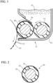
FIG. 1 shows a state of use of the developing roll in accordance with an embodiment of the present invention; -
FIG. 2 is a cross-sectional view of the developing roll according to the embodiment; -
FIG. 3 is a front view of the developing roll under a compression test; -
FIG. 4 is an enlarged cross-sectional view of the developing roll under the compression test; -
FIG. 5 is another enlarged cross-sectional view of the developing roll under the compression test; -
FIG. 6 is a load-displacement diagram obtained from the compression test; -
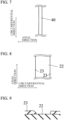
FIG. 7 is a plan view of the developing roll showing an abrasion mark that may occur on the surface of the developing roll; -
FIG. 8 is a plan view of the developing roll showing a peeling of the surface layer of the developing roll; -
FIG. 9 is a cross-sectional view of a developing roll showing the peeling of the surface layer of the developing roll; and -
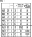
FIG. 10 is a table showing measurement results of indices of the surface layer of multiple samples of the developing roll and the results of the durability test of the samples. - Hereinafter, with reference to the accompanying drawings, an embodiment according to the present invention will be described. It is of note that the drawings are not necessarily to scale, and certain features may be exaggerated or omitted.
- As shown in
FIG. 1 , an electrophotographic image forming apparatus has aphotoconductor drum 10 and a developingunit 11. Thephotoconductor drum 10 rotates in the direction depicted by the arrow. Thedeveloper device 11 suppliestoner particles 12, which are a developing agent, to thephotoconductor drum 10. An electrostatic latent image is formed on the surface of thephotoconductor drum 10 by a latent image forming device (not shown), and thetoner particles 12 are transferred to the electrostatic latent image from the developingdevice 11, so that toner developed image with thetoner particles 12 is generated on the outer peripheral surface of thephotoconductor drum 10. - The developing
device 11 has atoner container 14 that stores amass 13 of toner particles, anelastic roll 15 disposed entirely within thetoner container 14, a developingroll 20 disposed partially within thetoner container 14, and a doctor blade 16 (regulation blade) supported by thetoner container 14. Theelastic roll 15 is pressed against the developingroll 20, and the developingroll 20 is pressed against thephotoconductor drum 10. Theelastic roll 15 and the developingroll 20 are rotated in directions indicated by the arrows, respectively, so that an almost constant amount of toner particles in thetoner container 14 adhere to the developingroll 20. Thus, a thin layer of the toner particles is formed on the outer peripheral surface of the developingroll 20. As the developingroll 20 rotates, the toner particles that adhere to the developingroll 20 are transported toward thephotoconductor drum 10. Thedoctor blade 16 positioned at the outlet for the toner particles in thetoner container 14 is pressed against the outer peripheral surface of the developingroll 20 to regulate the amount of toner particles that adhere to theroll 20 and are conveyed from thetoner container 14. Thus, the developingroll 20 is brought into contact with each of thephotoconductor drum 10, theelastic roll 15, and thedoctor blade 16 with a certain degree of force. - Although not shown, the developing
device 11 may be provided with a member that agitates themass 13 of toner particles in thetoner container 14, a screw for conveying the toner particles in thetoner container 14, etc. - As shown in
FIG. 2 , the developingroll 20 includes acylindrical core member 21 made of a metal, acore member 21 that is made of a rubber, is disposed around thecore member 21, and has a uniform thickness, and asurface layer 23 that is made of a rubber, is disposed around theelastic layer 22, and has a uniform thickness. The diameter of thecore member 21 is several millimeters, the thickness of theelastic layer 22 is 1 to 3 mm, and the thickness of thesurface layer 23 is several micrometers to several tens of micrometers. - Both the
elastic layer 22 and thesurface layer 23 are made of rubber. In the embodiment, both theelastic layer 22 and thesurface layer 23 are made of silicone rubber. However, theelastic layer 22 is provided to ensure the elasticity of the developingroll 20, and thesurface layer 23 is provided to improve the abrasion resistance of the surface of the developingroll 20. Therefore, components of the material of thesurface layer 23 are different from components of the material of theelastic layer 22. - In the embodiment, the
surface layer 23 was produced as follows: - First, the following materials were mixed in a first step.
- Urethane modified hexamethylene diisocyanate with solid contents of 80 weight percent (grade "E402-80B" of "DURANATE" (trade name) manufactured by Asahi Kasei Corporation (Tokyo, Japan)): 16.5 weight percent.
- Reactive silicone oil ("X-22-160AS" (trade name) manufactured by Shin-Etsu Chemical Co. (Tokyo, Japan)): 36.7 weight percent.
- Butyl acetate as a diluting solvent: 46.8 weight percent.
- The mixture was then left at 120 degrees Celsius for three hours to promote the reaction of the components, thereby producing a prepolymer.
- Next, the following materials were mixed in a second step.
- The prepolymer produced in the first step.
- Isocyanate with solid contents of 75 weight percent ("Desmodur L75" (trade name) manufactured by Sumika Covestro Urethane Co, Ltd. (Hyogo, Japan)) as a binder.
- Carbon dispersed liquid with solid contents of 20 to 30 weight percent ("MHI-BK" (trade name) manufactured by Mikuni Color Ltd. (Hyogo, Japan).
- Butyl acetate as a diluting solvent: 44.7 weight percent.
- Furthermore, in a third step, 2.6 weight percent of silicone rubber particles were added to the mixture obtained in the second step to produce a coating solution. The silicone rubber particles were "EP-2720" (trade name) manufactured by DuPont Toray Specialty Materials K.K. (Tokyo, Japan). The hardness of the silicone rubber particles measured with a durometer (Type A according to "JIS K 6253" and "ISO 7619") was 70 degrees. The average particle diameter of the silicone rubber particles was 2 µm.
- In a fourth step, the outer periphery of the
elastic layer 22 was coated with the coating solution, and the coating solution was cured, whereby thesurface layer 23 was produced. - The applicant adjusted the composition of the material of the
surface layer 23 and produced multiple samples with different properties in thesurface layer 23. Specifically, the applicant changed the proportions of the prepolymer, isocyanate, and the carbon dispersed liquid in the second step. - In each sample, the diameter of the
core member 21 was 6 mm, the thickness of theelastic layer 22 was 1.5 mm, and the thickness of thesurface layer 23 was 10 ± 2 µm. However, in one sample (sample 20 in FIG. 11), the thickness of thesurface layer 23 was 20 µm. - The applicant measured indices X and Y indicating the durability of the
surface layer 23 of each samples. The applicant also actually mounted the samples on a printer and tested the durability of the samples. -
FIGS. 3 to 5 show a compression test to measure the indices indicating the durability of thesurface layer 23 of each samples. For the compression test, acompression tester 30 was used. Thecompression tester 30 has a cylindricalmovable shaft 31 and aprobe 3 formed on the distal end of themovable shaft 31. Themovable shaft 31 andprobe 32 are made of a metal. Thecompression tester 30 can measure the displacement of theprobe 32 and the load given to theprobe 32 while automatically pushing down themovable shaft 31. - The
compression tester 30 used was "LNP nano touch" manufactured by Ludwig Nano Präzision GmbH (Nordheim, Germany). Theprobe 32 is truncated conical in shape with a diameter that decreases away from themovable shaft 31, and the diameter of the distal end of theprobe 32 was 40 µm. The apex angle θ of the truncated cone was 30 degrees. - As shown in
FIG. 3 , the distal end of theprobe 32 was brought into contact with the longitudinal center of the developingroll 20, and themovable shaft 31 was driven to push theprobe 32 in a normal direction of the outer peripheral surface (radial direction) of the developingroll 20. The pushing speed was about 50 µm/s and was almost constant since the V-control mode was selected in "LNP nano touch". The maximum depth of pushing was set slightly less than 1.5 mm, which was the thickness of theelastic layer 22. - During the pushing process, the displacement of the
probe 32 and the load applied to probe 32 were recorded. In "LNP nano touch", the resolution of displacement (increments of displacement reading) is 10 nm. From the recording results, values X1, Y, and Z1 were obtained. - The values X1 and Z1 were calculated from the following equations:


- Here, P1 was the load required to displace the developing
roll 20 by a depth of 100 µm in the radial direction when the truncated cone-shapedmetal probe 23 having a distal end of which the diameter d is 40 µm was pressed against the developingroll 20. In other words, P1 is the load applied to theprobe 32 in the state shown inFIG. 4 . D1 was the displacement of the developingroll 20 caused by theprobe 32 under the load P1. In short, D1 is the displacement of theprobe 32 in the state shown inFIG. 4 , and is about 100 µm, but in the pushing process, D1 was the recorded reading of the displacement of theprobe 32 when the recorded reading of the displacement of theprobe 32 exceeded 100 µm for the first time. More exactly, P1 was also the load at which the recorded reading of the displacement of theprobe 32 exceeded 100 µm for the first time during the pushing process. - The value A is the area of the distal end of the
probe 32 and is calculated from the following equation:
- The value Y was the displacement of the developing
roll 20 caused by theprobe 32 when theprobe 32, which was pressed against the developingroll 20 and was displaced in the radial direction of the developingroll 20, pierced (penetrated) thesurface layer 23 as shown inFIG. 5. FIG. 6 is a load-displacement diagram obtained from the compression test. The value Y is the amount of displacement when a sudden drop in load occurs, as shown inFIG. 6 . The value Y was obtained from the compression test, but corresponds to the breaking elongation in terms of tensile tests. However, the value Y is the amount of deformation, expressed in µm, whereas the breaking elongation is a strain obtained by dividing the amount of deformation by the original total length, and thus, the breaking elongation is a dimensionless quantity. The value Y is an index of the compressive toughness of thesurface layer 23. - On the other hand, the value X1 can be considered to be an index of the compressive strength (in short, hardness) of the developing
roll 20. However, X1 is influenced by not only the hardness of thesurface layer 23, but also the hardness of theelastic layer 22. Accordingly, a material roll (not shown) that has thecore member 21 and theelastic layer 22 and does not have thesurface layer 23 was prepared, and a value X2 and a value Z2 were calculated for the material roll from the following equations:


- Here, P2 was the load required to displace the
material roll 20 by a depth of 100 µm in the radial direction when theprobe 32 was pressed against the material roll. D2 was the displacement of the material roll caused by the probe under the load P2. D2 is about 100 µm, but in the pushing process, D2 was the recorded reading of the displacement of theprobe 32 when the recorded reading of the displacement of theprobe 32 exceeded 100 µm for the first time. More exactly, P2 was also the load at which the recorded reading of the displacement of theprobe 32 exceeded 100 µm for the first time during the pushing process. - Then, values X and Z in which the effect of the hardness of the
elastic layer 22 are canceled out were calculated from the following equations:

- Therefore, the values X and Z can be calculated from the following equations:


- The values X and Z can be considered to be indices of the compressive strength (in short, hardness) of the
surface layer 23. Specifically, the value X is approximately equal to the force required to displace the developingroll 20 and the material roll by 100 µm in a radial direction by theprobe 32 divided by the volume of theprobe 32 impaling the roll. The value X is equal to the force required to displace the developingroll 20 and the material roll by 100 µm in a radial direction by theprobe 32 divided by the area of the distal end of theprobe 32. - In the durability test, each sample was mounted on a color printer "HL-L8360CDW" (trade name) manufactured by Brother Industries, Ltd. (Aichi, Japan). The printer was then used to print, and after printing on 6000 sheets of A4 paper with the use of each sample, it was determined, with human eyes, whether or not the
surface layer 23 had one or more abrasion marks and whether or not one or more peelings of thesurface layer 23 occurred. In the printing, a uniform image of 1% density was formed over the entire surface of each sheet. - Excessive wear (abrasion) of the
surface layer 23 appears as a linear abrasion mark (wear mark) 40 on thesurface layer 23 as shown in the plan view of the developingroll 20 inFIG. 7 . Theabrasion mark 40 extend along the circumferential direction of the developingroll 20. This is because a portion of thedoctor blade 16, which is in contact with the outer peripheral surface of the rotating developingroll 20, wears (abrades) thesurface layer 23. - Peeling of the
surface layer 23 results in exposure of theelastic layer 22, as shown inFIG. 8 (plan view) andFIG. 9 (cross-sectional view). -
FIG. 10 shows the values X, Y, and Z of the samples and the results of the durability test of the samples. In samples 1-12 and 20, neither abrasion mark nor peeling occurred on thesurface layer 23. In samples 13-19, one or more abrasion marks or one or more peelings occurred on thesurface layer 23. - The results shown in
FIG. 10 indicate that it is preferable that the value X be equal to or greater than 65.6 N/mm3, and that the value Y be equal to or greater than 229 µm. In addition, it will be understood that it is preferable that the value Z be equal to or greater than 6.56 N/mm2, and that the value Y be equal to or greater than 229 µm. The values X and Z are kinds of indices of the compressive strength of thesurface layer 23. By having a value X equal to or greater than 65.6 N/mm3, thesurface layer 23 has less abrasion. By having a value Z equal to or greater than 6.56 N/mm2, thesurface layer 23 has less abrasion. Insamples 13 to 15, in which the values X and Z are smaller, one or more abrasion marks occurred on thesurface layer 23. - The value Y is an index of the compressive toughness of the
surface layer 23. By having a value Y equal to or greater than 229 µm, thesurface layer 23 is less likely to peel off from theelastic layer 22. In samples 16-19, in which the value Y is smaller, peeling of thesurface layer 23 occurred. - Thus, if the value X is equal to or greater than 65.6 N/mm3 and the value Y is equal to or greater than 229 µm, the developing
roll 20 is highly durable to achieve a long life span. Similarly, if the value Z is equal to or greater than 6.56 N/mm2 and the value Y is equal to or greater than 229 µm, the developingroll 20 has high durability to achieve a long life span. - Although preferred upper limits of the values X, Y, and Z are unknown, neither abrasion marks nor peelings occurred on the
surface layer 23 ofsample 12, of which the value X is 215.5 N/mm3 and the value Z is 21.55 N/mm2, and neither abrasion marks nor peelings occurred on thesurface layer 23 ofsample 1, of which the value Y is 890 µm. Accordingly, a preferred range for the value X includes at least the range from 65.6 N/mm3 to 215.5 N/mm3, and a preferred range for the value Y includes at least the range from 229 µm to 890 µm. A preferred range for the value Z includes at least the range from 6.56 N/mm2 to 21.55 N/mm2. - The thickness of the
surface layer 23 ofsample 20 is 20 µm, which is greater than the thickness of thesurface layer 23 of the other samples. The material composition of thesurface layer 23 ofsample 20 is the same as that of thesurface layer 23 ofsample 2. The sole difference betweensamples surface layer 23.Samples surface layer 23 varies, it is considered that it is preferable that the value X be equal to or greater than 65.6 N/mm3 and the value Ybe equal to or greater than 229 µm. Similarly, it is considered that it is preferable that the value Z be equal to or greater than 6.56 N/mm2, and that the value Y be equal to or greater than 229 µm. - The present invention has been shown and described with reference to preferred embodiments thereof. However, it will be understood by those skilled in the art that various changes in form and detail may be made without departing from the scope of the invention as defined by the claims. Such variations, alterations, and modifications are intended to be encompassed in the scope of the present invention.
-
- 20:
- Developing roll
- 21:
- Core member
- 22:
- Elastic layer
- 23:
- Surface layer
Claims (4)
- A developing roll used in an electrophotographic image forming apparatus, the developing roll comprising: a core member made of a metal; an elastic layer made of a rubber disposed around the core member; and a surface layer disposed around the elastic layer,wherein a value X is equal to or greater than 65.6 N/mm3 and a value Y is equal to or greater than 229 µm, wherein the value X is calculated from the following equation:
 where P1 is a load required to displace the developing roll by a depth of 100 µm in a radial direction when a truncated cone-shaped metal probe having a distal end of which a diameter is 40 µm is pressed against the developing roll, D1 is a displacement of the developing roll caused by the probe under the load P1, A is an area of the distal end of the probe,P2 is a load required to displace a material roll by a depth of 100 µm in a radial direction when the probe is pressed against the material roll that includes the core member and the elastic layer and does not include the surface layer, D2 is a displacement of the material roll caused by the probe under the load P2,the value Y is a displacement of the developing roll caused by the probe when the probe, which is pressed against the developing roll and is displaced in a radial direction of the developing roll, pierces the surface layer.
 - The developing roll according to claim 1, wherein the value X is equal to or less than 215.5 N/mm3, and wherein the value Y is equal to or greater than 890 µm.
- A developing roll used in an electrophotographic image forming apparatus, the developing roll comprising: a core member made of a metal; an elastic layer made of a rubber disposed around the core member; and a surface layer disposed around the elastic layer,wherein a value Z is equal to or greater than 6.56 N/mm2 and a value Y is equal to or greater than 229 µm, wherein the value X is calculated from the following equation:
 where P1 is a load required to displace the developing roll by a depth of 100 µm in a radial direction when a truncated cone-shaped metal probe having a distal end of which a diameter is 40 µm is pressed against the developing roll, P2 is a load required to displace a material roll by a depth of 100 µm in a radial direction when the probe is pressed against the material roll that includes the core member and the elastic layer and does not include the surface layer, A is an area of the distal end of the probe,the value Y is a displacement of the developing roll caused by the probe when the probe, which is pressed against the developing roll and is displaced in a radial direction of the developing roll, pierces the surface layer.
 - The developing roll according to claim 1, wherein the value Z is equal to or less than 21.55 N/mm2, and wherein the value Y is equal to or greater than 890 µm.
Applications Claiming Priority (2)
| Application Number | Priority Date | Filing Date | Title |
|---|---|---|---|
| JP2020105318 | 2020-06-18 | ||
| PCT/JP2021/010621 WO2021256028A1 (en) | 2020-06-18 | 2021-03-16 | Developer roller |
Publications (4)
| Publication Number | Publication Date |
|---|---|
| EP4170433A1 true EP4170433A1 (en) | 2023-04-26 |
| EP4170433A4 EP4170433A4 (en) | 2023-11-15 |
| EP4170433B1 EP4170433B1 (en) | 2026-01-28 |
| EP4170433C0 EP4170433C0 (en) | 2026-01-28 |
Family
ID=79267779
Family Applications (1)
| Application Number | Title | Priority Date | Filing Date |
|---|---|---|---|
| EP21825200.5A Active EP4170433B1 (en) | 2020-06-18 | 2021-03-16 | Developer roller |
Country Status (5)
| Country | Link |
|---|---|
| US (1) | US11934110B2 (en) |
| EP (1) | EP4170433B1 (en) |
| JP (1) | JP7499331B2 (en) |
| CN (1) | CN115702393B (en) |
| WO (1) | WO2021256028A1 (en) |
Family Cites Families (16)
| Publication number | Priority date | Publication date | Assignee | Title |
|---|---|---|---|---|
| CA2254838C (en) * | 1997-12-26 | 2007-06-19 | Nitto Kogyo Co., Ltd. | Developing roller and method of producing the same |
| JP3994576B2 (en) * | 1998-06-05 | 2007-10-24 | 東海ゴム工業株式会社 | Toner supply roll |
| JP2002372855A (en) | 2001-04-13 | 2002-12-26 | Canon Chemicals Inc | Developer quantity regulating blade, developing device and production method for the blade |
| JP4174266B2 (en) * | 2002-08-21 | 2008-10-29 | キヤノン株式会社 | Developing roller for image forming apparatus |
| JP2004317731A (en) * | 2003-04-15 | 2004-11-11 | Canon Chemicals Inc | Roller for image forming apparatus and image forming apparatus |
| JP2005172941A (en) * | 2003-12-08 | 2005-06-30 | Sharp Corp | Non-magnetic one-component developing device and toner used therefor |
| JP2005352089A (en) * | 2004-06-09 | 2005-12-22 | Bridgestone Corp | Developing roller and image forming apparatus using the same |
| JP2006276714A (en) * | 2005-03-30 | 2006-10-12 | Canon Inc | Development method and developer carrier used in the development method |
| JP4402137B2 (en) * | 2007-06-29 | 2010-01-20 | キヤノン株式会社 | Image forming apparatus, developing device and cartridge |
| CN100535786C (en) * | 2007-09-28 | 2009-09-02 | 横店集团东磁股份有限公司 | Developer roll and method of producing the same |
| WO2015098310A1 (en) * | 2013-12-27 | 2015-07-02 | Nok株式会社 | Rubber member for covering development roll, and method for producing development roll for image formation device |
| WO2015156330A1 (en) * | 2014-04-08 | 2015-10-15 | Nok株式会社 | Rubber member for developing roll, and method for manufacturing same |
| JP2018005017A (en) * | 2016-07-05 | 2018-01-11 | サムスン エレクトロニクス カンパニー リミテッド | External additive for toner and method for manufacturing the same, and toner |
| JP6303095B1 (en) * | 2016-08-04 | 2018-04-04 | Nok株式会社 | Conductive roll |
| JP6629491B2 (en) * | 2017-06-27 | 2020-01-15 | Nok株式会社 | Developing roller |
| US10935903B2 (en) * | 2018-04-19 | 2021-03-02 | Canon Kabushiki Kaisha | Developing roller, process cartridge and image forming apparatus |
-
2021
- 2021-03-16 CN CN202180039642.0A patent/CN115702393B/en active Active
- 2021-03-16 WO PCT/JP2021/010621 patent/WO2021256028A1/en not_active Ceased
- 2021-03-16 EP EP21825200.5A patent/EP4170433B1/en active Active
- 2021-03-16 US US17/927,443 patent/US11934110B2/en active Active
- 2021-03-16 JP JP2022532301A patent/JP7499331B2/en active Active
Also Published As
| Publication number | Publication date |
|---|---|
| CN115702393A (en) | 2023-02-14 |
| JPWO2021256028A1 (en) | 2021-12-23 |
| EP4170433B1 (en) | 2026-01-28 |
| EP4170433C0 (en) | 2026-01-28 |
| US11934110B2 (en) | 2024-03-19 |
| JP7499331B2 (en) | 2024-06-13 |
| WO2021256028A1 (en) | 2021-12-23 |
| US20230221661A1 (en) | 2023-07-13 |
| CN115702393B (en) | 2025-07-11 |
| EP4170433A4 (en) | 2023-11-15 |
Similar Documents
| Publication | Publication Date | Title |
|---|---|---|
| EP2348367B1 (en) | Developing roller, process cartridge, and electrophotographic image-forming apparatus | |
| US8768226B2 (en) | Developer support member, electrophotographic process cartridge and electrophotographic image forming apparatus | |
| US7570905B2 (en) | Developing roller, developing apparatus using the same, and image forming apparatus | |
| EP3026494A2 (en) | Electroconductive member for electrophotography, process cartridge, and electrophotographic image-forming apparatus | |
| JP2019191580A (en) | Developing roller, process cartridge, and image forming apparatus | |
| JP2005292324A (en) | Image forming apparatus cleaning device | |
| EP4170433B1 (en) | Developer roller | |
| JP5889139B2 (en) | Developer supply member, developing device, and image forming apparatus | |
| US12282268B2 (en) | Developing roll and developing device for use in image-forming apparatus using electrophotography | |
| US11921439B2 (en) | Developing roll | |
| JP2016099527A (en) | Developing roller, developing device, and image forming apparatus | |
| JP5241471B2 (en) | Developing roller, developing device using the same, process cartridge, and image forming apparatus | |
| US12197161B2 (en) | Cleaning blade | |
| JP4551738B2 (en) | Developing roller, process cartridge, and image forming apparatus | |
| JP4992589B2 (en) | Toner supply roller and image forming apparatus | |
| US20070003327A1 (en) | Toner supply members for an image forming device | |
| JP2010152127A (en) | Electrophotographic process cartridge, and developing method using the same | |
| JP2009063807A (en) | Developing device | |
| JP2020190647A (en) | Image formation apparatus | |
| JP2003029525A (en) | Toner supply roller and developing device | |
| JP2001324865A (en) | Toner supply roller and developing device | |
| JP2003029524A (en) | Toner supply roller and developing device |
Legal Events
| Date | Code | Title | Description |
|---|---|---|---|
| STAA | Information on the status of an ep patent application or granted ep patent |
Free format text: STATUS: THE INTERNATIONAL PUBLICATION HAS BEEN MADE |
|
| PUAI | Public reference made under article 153(3) epc to a published international application that has entered the european phase |
Free format text: ORIGINAL CODE: 0009012 |
|
| STAA | Information on the status of an ep patent application or granted ep patent |
Free format text: STATUS: REQUEST FOR EXAMINATION WAS MADE |
|
| 17P | Request for examination filed |
Effective date: 20221123 |
|
| AK | Designated contracting states |
Kind code of ref document: A1 Designated state(s): AL AT BE BG CH CY CZ DE DK EE ES FI FR GB GR HR HU IE IS IT LI LT LU LV MC MK MT NL NO PL PT RO RS SE SI SK SM TR |
|
| DAV | Request for validation of the european patent (deleted) | ||
| DAX | Request for extension of the european patent (deleted) | ||
| A4 | Supplementary search report drawn up and despatched |
Effective date: 20231018 |
|
| RIC1 | Information provided on ipc code assigned before grant |
Ipc: G03G 15/08 20060101AFI20231012BHEP |
|
| GRAP | Despatch of communication of intention to grant a patent |
Free format text: ORIGINAL CODE: EPIDOSNIGR1 |
|
| STAA | Information on the status of an ep patent application or granted ep patent |
Free format text: STATUS: GRANT OF PATENT IS INTENDED |
|
| INTG | Intention to grant announced |
Effective date: 20251028 |
|
| GRAS | Grant fee paid |
Free format text: ORIGINAL CODE: EPIDOSNIGR3 |
|
| GRAA | (expected) grant |
Free format text: ORIGINAL CODE: 0009210 |
|
| STAA | Information on the status of an ep patent application or granted ep patent |
Free format text: STATUS: THE PATENT HAS BEEN GRANTED |
|
| AK | Designated contracting states |
Kind code of ref document: B1 Designated state(s): AL AT BE BG CH CY CZ DE DK EE ES FI FR GB GR HR HU IE IS IT LI LT LU LV MC MK MT NL NO PL PT RO RS SE SI SK SM TR |
|
| REG | Reference to a national code |
Ref country code: CH Ref legal event code: F10 Free format text: ST27 STATUS EVENT CODE: U-0-0-F10-F00 (AS PROVIDED BY THE NATIONAL OFFICE) Effective date: 20260128 Ref country code: GB Ref legal event code: FG4D |
|
| REG | Reference to a national code |
Ref country code: DE Ref legal event code: R096 Ref document number: 602021047117 Country of ref document: DE |
|
| REG | Reference to a national code |
Ref country code: IE Ref legal event code: FG4D |
|
| U01 | Request for unitary effect filed |
Effective date: 20260210 |
|
| U07 | Unitary effect registered |
Designated state(s): AT BE BG DE DK EE FI FR IT LT LU LV MT NL PT RO SE SI Effective date: 20260216 |
|
| U20 | Renewal fee for the european patent with unitary effect paid |
Year of fee payment: 6 Effective date: 20260330 |