EP4170328A1 - Fusion system and method for radiation imaging and radioactive material monitoring - Google Patents
Fusion system and method for radiation imaging and radioactive material monitoring Download PDFInfo
- Publication number
- EP4170328A1 EP4170328A1 EP21828334.9A EP21828334A EP4170328A1 EP 4170328 A1 EP4170328 A1 EP 4170328A1 EP 21828334 A EP21828334 A EP 21828334A EP 4170328 A1 EP4170328 A1 EP 4170328A1
- Authority
- EP
- European Patent Office
- Prior art keywords
- subsystem
- luggage
- radioactive material
- package object
- radiation imaging
- Prior art date
- Legal status (The legal status is an assumption and is not a legal conclusion. Google has not performed a legal analysis and makes no representation as to the accuracy of the status listed.)
- Pending
Links
Images


Classifications
-
- G—PHYSICS
- G01—MEASURING; TESTING
- G01N—INVESTIGATING OR ANALYSING MATERIALS BY DETERMINING THEIR CHEMICAL OR PHYSICAL PROPERTIES
- G01N23/00—Investigating or analysing materials by the use of wave or particle radiation, e.g. X-rays or neutrons, not covered by groups G01N3/00 – G01N17/00, G01N21/00 or G01N22/00
- G01N23/02—Investigating or analysing materials by the use of wave or particle radiation, e.g. X-rays or neutrons, not covered by groups G01N3/00 – G01N17/00, G01N21/00 or G01N22/00 by transmitting the radiation through the material
- G01N23/04—Investigating or analysing materials by the use of wave or particle radiation, e.g. X-rays or neutrons, not covered by groups G01N3/00 – G01N17/00, G01N21/00 or G01N22/00 by transmitting the radiation through the material and forming images of the material
-
- G—PHYSICS
- G01—MEASURING; TESTING
- G01T—MEASUREMENT OF NUCLEAR OR X-RADIATION
- G01T1/00—Measuring X-radiation, gamma radiation, corpuscular radiation, or cosmic radiation
- G01T1/16—Measuring radiation intensity
- G01T1/167—Measuring radioactive content of objects, e.g. contamination
-
- G—PHYSICS
- G01—MEASURING; TESTING
- G01V—GEOPHYSICS; GRAVITATIONAL MEASUREMENTS; DETECTING MASSES OR OBJECTS; TAGS
- G01V5/00—Prospecting or detecting by the use of ionising radiation, e.g. of natural or induced radioactivity
- G01V5/20—Detecting prohibited goods, e.g. weapons, explosives, hazardous substances, contraband or smuggled objects
- G01V5/22—Active interrogation, i.e. by irradiating objects or goods using external radiation sources, e.g. using gamma rays or cosmic rays
-
- G—PHYSICS
- G01—MEASURING; TESTING
- G01V—GEOPHYSICS; GRAVITATIONAL MEASUREMENTS; DETECTING MASSES OR OBJECTS; TAGS
- G01V5/00—Prospecting or detecting by the use of ionising radiation, e.g. of natural or induced radioactivity
- G01V5/20—Detecting prohibited goods, e.g. weapons, explosives, hazardous substances, contraband or smuggled objects
- G01V5/22—Active interrogation, i.e. by irradiating objects or goods using external radiation sources, e.g. using gamma rays or cosmic rays
- G01V5/223—Mixed interrogation beams, e.g. using more than one type of radiation beam
-
- G—PHYSICS
- G01—MEASURING; TESTING
- G01V—GEOPHYSICS; GRAVITATIONAL MEASUREMENTS; DETECTING MASSES OR OBJECTS; TAGS
- G01V5/00—Prospecting or detecting by the use of ionising radiation, e.g. of natural or induced radioactivity
- G01V5/20—Detecting prohibited goods, e.g. weapons, explosives, hazardous substances, contraband or smuggled objects
- G01V5/26—Passive interrogation, i.e. by measuring radiation emitted by objects or goods
-
- G—PHYSICS
- G01—MEASURING; TESTING
- G01N—INVESTIGATING OR ANALYSING MATERIALS BY DETERMINING THEIR CHEMICAL OR PHYSICAL PROPERTIES
- G01N2223/00—Investigating materials by wave or particle radiation
- G01N2223/03—Investigating materials by wave or particle radiation by transmission
-
- G—PHYSICS
- G01—MEASURING; TESTING
- G01N—INVESTIGATING OR ANALYSING MATERIALS BY DETERMINING THEIR CHEMICAL OR PHYSICAL PROPERTIES
- G01N2223/00—Investigating materials by wave or particle radiation
- G01N2223/10—Different kinds of radiation or particles
- G01N2223/101—Different kinds of radiation or particles electromagnetic radiation
- G01N2223/1013—Different kinds of radiation or particles electromagnetic radiation gamma
-
- G—PHYSICS
- G01—MEASURING; TESTING
- G01N—INVESTIGATING OR ANALYSING MATERIALS BY DETERMINING THEIR CHEMICAL OR PHYSICAL PROPERTIES
- G01N2223/00—Investigating materials by wave or particle radiation
- G01N2223/10—Different kinds of radiation or particles
- G01N2223/101—Different kinds of radiation or particles electromagnetic radiation
- G01N2223/1016—X-ray
-
- G—PHYSICS
- G01—MEASURING; TESTING
- G01N—INVESTIGATING OR ANALYSING MATERIALS BY DETERMINING THEIR CHEMICAL OR PHYSICAL PROPERTIES
- G01N2223/00—Investigating materials by wave or particle radiation
- G01N2223/10—Different kinds of radiation or particles
- G01N2223/106—Different kinds of radiation or particles neutrons
-
- G—PHYSICS
- G01—MEASURING; TESTING
- G01N—INVESTIGATING OR ANALYSING MATERIALS BY DETERMINING THEIR CHEMICAL OR PHYSICAL PROPERTIES
- G01N2223/00—Investigating materials by wave or particle radiation
- G01N2223/30—Accessories, mechanical or electrical features
- G01N2223/33—Accessories, mechanical or electrical features scanning, i.e. relative motion for measurement of successive object-parts
- G01N2223/3308—Accessories, mechanical or electrical features scanning, i.e. relative motion for measurement of successive object-parts object translates
-
- G—PHYSICS
- G01—MEASURING; TESTING
- G01N—INVESTIGATING OR ANALYSING MATERIALS BY DETERMINING THEIR CHEMICAL OR PHYSICAL PROPERTIES
- G01N2223/00—Investigating materials by wave or particle radiation
- G01N2223/50—Detectors
-
- G—PHYSICS
- G01—MEASURING; TESTING
- G01N—INVESTIGATING OR ANALYSING MATERIALS BY DETERMINING THEIR CHEMICAL OR PHYSICAL PROPERTIES
- G01N2223/00—Investigating materials by wave or particle radiation
- G01N2223/60—Specific applications or type of materials
- G01N2223/626—Specific applications or type of materials radioactive material
-
- G—PHYSICS
- G01—MEASURING; TESTING
- G01N—INVESTIGATING OR ANALYSING MATERIALS BY DETERMINING THEIR CHEMICAL OR PHYSICAL PROPERTIES
- G01N2223/00—Investigating materials by wave or particle radiation
- G01N2223/60—Specific applications or type of materials
- G01N2223/643—Specific applications or type of materials object on conveyor
Definitions
- Embodiments of the present disclosure generally relate to a field of security inspection of a luggage or package object, and in particular, to a system and a method capable of integrating a radiation imaging and a radioactive substance monitoring.
- the radioactive material monitoring has been widely used in customs, borders, nuclear power stations and other places for entrance and exit detections to fight against an illegal transfer and transportation of radioactive materials and prevent a risk of radioactive material proliferation.
- a gamma ray or a neutron ray emitted by a radioactive material is mainly detected to identify whether a radioactive material is contained.
- the X-ray imaging technology has a wide range of important applications in the field of security inspection, medical diagnosis, industrial non-destructive testing, etc. It may efficiently detect dangerous explosives, flammable and corrosive materials or other dangerous and contraband goods hidden in objects through visual images in application scenarios such as customs ports, civil aviation logistics, and railway transportation.
- radioactive material monitoring technology and the X-ray imaging technology have many overlapping portions in application scenarios.
- entrance and exit detection places such as customs and borders, due to the needs of detection, it is not uncommon that radioactive material monitoring devices and X-ray imaging devices exist at the same time.
- radioactive material monitoring devices and X-ray imaging devices exist at the same time.
- an X-ray emitted in an X-ray imaging will interfere with a radioactive material monitoring, and the two may not be performed at the same time.
- a low energy X-ray source based on a hot cathode In the field of luggage or package security inspection imaging, a low energy X-ray source based on a hot cathode is often used.
- X-ray source electrons are emitted by heating a filament, and an anode target is bombarded under an action of an accelerating electric field to generate an X-ray.
- a period of heating time usually hundreds of milliseconds, is required from heating the filament to emitting electrons to generate an X-ray.
- generation of an X-ray is not immediate, and it usually takes hundreds of milliseconds to several seconds to work again if an interruption occurs.
- an X-ray source Based on the characteristic that the generation of such an X-ray requires a certain delay, an X-ray source usually works continuously.
- a commonly used low-energy X-ray imaging device needs to continuously generate X-rays, and this inevitably causes radiation interferences to a radioactive material monitoring device, makes it impossible for the radioactive monitoring device to effectively distinguish whether radioactive information comes from a detected object or from the X-ray imaging device.
- a radioactive material monitoring device and an X-ray imaging device are usually arranged separately, or they are arranged adjacent to each other after a shielding is added, or a limited converging is made in the accelerator light source imaging technology.
- An additional transitional space is required to arrange the two types of devices separately, and this will increase the number and time of the object detection and reduce the efficiency of the object detection.
- Arranging the two types of devices adjacent to each other after a shielding is added solves the problem, but the additional shielding structure brings additional space requirements, increases partial costs, and greatly limits the arrangement flexibility of radioactive material monitoring components.
- the radioactive information of the detected object and the X-ray image information of the detected object are not dynamically integrated, and as a result the improvement of the detection efficiency of an object is limited.
- the accelerator light source imaging technology is converged with the radioactive material monitoring to some extent to achieve the radiation imaging inspection and the radioactive material monitoring.
- this method is limited by the application scope of the accelerator light source and may not be used in an application such as an ordinary luggage security inspection.
- An accelerator X-ray source usually produces an X-ray having a high energy, often in a magnitude of megaelectron volts, is mostly used in the field of imaging of large-scale cargos and vehicles, and is often seen at circulation gates of large-scale cargos and vehicles in customs, borders, etc. Due to the high energy and strong penetrating power of the X-ray, a high safety protection is required during a normal operation.
- the volume of the device is large, and the overall floor area is large.
- an X-ray energy is required to be in a magnitude of kiloelectron volts.
- the security protection requirements for the overall device are high, the device needs to occupy a small area and is convenient for deployment. That is, an accelerator light source is not applicable for a radiation imaging in the field of luggage and package imaging inspection.
- the present disclosure is provided in order to overcome at least one of the above and other problems and defects in the related art.
- a converged system for performing a radiation imaging and a radioactive material monitoring on a luggage or package object including: a radiation imaging subsystem configured to operate in a pulse mode to perform a radiation imaging on the luggage or package object; a radioactive material monitoring subsystem configured to operate in a pulse mode to monitor whether the luggage or package object contains a radioactive material; and a synchronization control subsystem being in communication with both the radiation imaging subsystem and the radioactive material monitoring subsystem, and configured to control the radiation imaging subsystem and the radioactive material monitoring subsystem to operate alternately.
- the radiation imaging subsystem includes: a radiation source configured to generate a radiation beam in a pulse mode for irradiating the luggage or package object; and a radiation imaging detector configured to detect a ray emitted or generated by the luggage or package object under an irradiation of the radiation beam, so as to generate data for forming an image of the luggage or package object.
- the radiation source is a low-energy X-ray source capable of a controllable pulse emission, especially a fast-pulse low-energy X-ray source capable of a fast pulse emission switching between tens of microseconds and tens of milliseconds.
- the ray source includes an X-ray source generating a cathode electron by pulsing, such as an X-ray source based on a carbon nanotube cathode and a hot cathode X-ray source having a grid control gate.
- the ray source may also include a pulse X-ray source of a single target and a pulse distributed X-ray source of multiple targets.
- the radioactive material monitoring subsystem includes a radioactivity monitoring detector configured to operate in a pulse mode to monitor a radioactive ray emitted by the luggage or package object.
- the radioactivity monitoring detector includes at least one of a gamma ray detector and a neutron detector.
- the synchronization control subsystem is configured to control the radiation imaging subsystem and the radioactive material monitoring subsystem to operate alternately in real time through a variable and adjustable pulse control signal.
- the radiation imaging subsystem is configured to operate according to a first pulse control signal to perform the radiation imaging on the luggage or package object
- the radioactive material monitoring subsystem is configured to operate according a second pulse control signal to monitor whether the luggage or package object contains a radioactive material
- the first pulse control signal and the second pulse control signal include rectangular waves.
- the first pulse control signal includes a plurality of first pulses
- the second pulse control signal includes second pulses
- the radioactive material monitoring subsystem being configured to operate during the second pulses to monitor a radioactive ray emitted by the luggage or package object, and each of some or all of the second pulses is between two adjacent first pulses in time, and a spacing between adjacent first pulses is greater than or equal to a pulse width of the second pulses.
- the converged system further includes: a transmission subsystem configured to transport the luggage or package obj ect to pass through a detection region, and output a transmission signal indicating times when the luggage or package object enters and leaves the detection region and a transporting speed of the luggage or package object to at least the synchronization control subsystem, wherein the synchronization control subsystem is further configured to control operations of the radiation imaging subsystem and the radioactive material monitoring subsystem based on the transmission signal.
- a fast switching within a short period between tens of microseconds to tens of milliseconds may be achieved through a fast pulse, so that X-ray perspective imaging information of the detected object and radioactive ray intensity information of the detected object may be acquired quickly and alternately during an uniform or continuous transporting process (without pausing or waiting) of the transmission subsystem.
- the converged system further includes: an information converging subsystem configured to be in communication with the radioactive material monitoring subsystem and the radiation imaging subsystem, so as to converge a radioactivity information of the luggage or package object obtained by the radioactive material monitoring subsystem into the image of the luggage or package object obtained by the radiation imaging subsystem.
- a method for performing a radiation imaging and a radioactive material monitoring on a luggage or package object including: operating a radiation imaging subsystem in a pulse mode to perform a radiation imaging on the luggage or package object; operating a radioactive material monitoring subsystem in a pulse mode to monitor whether the luggage or package object contains a radioactive material; and controlling the radiation imaging subsystem and the radioactive material monitoring subsystem to operate alternately by a synchronization control subsystem.
- the operating a radiation imaging subsystem in a pulse mode to perform a radiation imaging on the luggage or package object includes: generating a radiation beam in a pulse mode to irradiate the luggage or package object by a low-energy X-ray source capable of a controllable pulse emission; and detecting a ray emitted or generated by the luggage or package object under an irradiation of the radiation beam to generate data for forming an image of the luggage or package object by a radiation imaging detector.
- the operating a radioactive material monitoring subsystem in the pulse mode to monitor whether the luggage or package object contains a radioactive material includes: operating a radioactivity monitoring detector in a pulse mode to monitor a radioactive ray emitted by the luggage or package object.
- At least one of a gamma ray and a neutron ray emitted by the luggage or package object is monitored by the radioactivity monitoring detector.
- the radiation imaging subsystem and the radioactive material monitoring subsystem are controlled in real time to operate alternately by the synchronization control subsystem through a variable and adjustable pulse control signal.
- the radiation imaging subsystem is controlled to operate according to a first pulse control signal to perform the radiation imaging on the luggage or package object
- the radioactive material monitoring subsystem is controlled to operate according a second pulse control signal to monitor whether the luggage or package object contains a radioactive material
- the first pulse control signal and the second pulse control signal include rectangular waves.
- the first pulse control signal includes a plurality of first pulses
- the second pulse control signal includes second pulses
- the radioactive material monitoring subsystem operating during the second pulses to monitor a radioactive ray emitted by the luggage or package object, and each of some or all of the second pulses is between two adjacent first pulses in time, and a spacing between adjacent first pulses is greater than or equal to a pulse width of the second pulses.
- the method further includes: transporting the luggage or package object to pass through a detection region, and outputting a transmission signal indicating times when the luggage or package object enters and leaves the detection region and a transporting speed of the luggage or package object to at least the synchronization control subsystem by a transmission subsystem, and controlling operations of the radiation imaging subsystem and the radioactive material monitoring subsystem by the synchronization control subsystem based on the transmission signal.
- the method further includes: converging a radioactivity information of the luggage or package object obtained by the radioactive material monitoring subsystem into the image of the luggage or package object obtained by the radiation imaging subsystem.
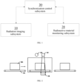
- FIG. 1 schematically shows an arrangement of a converged system for performing a radiation imaging and a radioactive material monitoring according to an exemplary embodiment of the present disclosure.
- the converged system is deployed in sites such as customs, airports, subways, stations, and public places, so as to perform a security inspection on a luggage or package object carried by a person or transported through an express delivery.
- the converged system includes a radiation imaging subsystem 10, a radioactive material monitoring subsystem 20 and a synchronization control subsystem 30.
- the radiation imaging subsystem 10 may operate in a pulse mode or in a discontinuous mode (e.g., be activated or operate intermittently) to perform a radiation imaging, such as a low energy radiation imaging, on the luggage or package object, and it may include, for example, an X-ray imaging system.
- a radiation imaging such as a low energy radiation imaging, on the luggage or package object
- it may include, for example, an X-ray imaging system.
- “low energy” or “low energy radiation imaging” described herein is mentioned relative to a high energy radiation source such as an accelerator source, and is applicable for a radiation imaging, such as a radiation imaging having an X-ray energy in a magnitude of kiloelectron volts (kev), of a luggage or package object in the above locations.
- kev kiloelectron volts
- the radioactive material monitoring subsystem 20 may also operate in a pulse mode or in a discontinuous mode to monitor whether the luggage or package object contains a radioactive material.
- the synchronization control subsystem 30 is in communication with the radiation imaging subsystem 10 and the radioactive material monitoring subsystem 20, and controls the radiation imaging subsystem and the radioactive material monitoring subsystem to operate alternately, so as to perform a radiation imaging and a radioactive material monitoring on a same luggage or package object, thereby improving the detection efficiency.
- a radiation imaging operation will not affect or interfere with a radioactive material monitoring operation, and the radiation imaging subsystem and the radioactive material monitoring subsystem may be arranged adjacent to each other or arranged in a compact manner without an additional shielding structure being arranged therebetween, thereby reducing the costs and improving the flexibility in arrangement of system components.
- the synchronization control subsystem is used to coordinate (e.g., in time sequence) operations of both the radiation imaging subsystem and the radioactive material monitoring subsystem, and ensure that the operations of the two do not interfere with each other.
- the synchronization control subsystem may be implemented by various suitable hardware/software, including various controllers, control modules or application programs. For example, they may be converged in an inspection operating stage, converged in a control mechanism of the radiation imaging subsystem and/or the radioactive material monitoring subsystem, or arranged separately.
- the present disclosure does not specifically limit thereto.
- the radiation imaging subsystem at least includes a radiation source and a radiation imaging detector.
- the radiation source generates a radiation beam in a pulse mode or in an intermittent mode for irradiating the luggage or package object
- the radiation imaging detector detects a ray emitted or generated (e.g., scattered, reflected or transmitted) by the luggage or package object under an irradiation of the radiation beam to generate data, such as an electrical signal, for forming an image of the luggage or package object.
- the radiation source includes a low-energy X-ray source capable of a controllable pulse emission, especially a fast-pulse low-energy X-ray source capable of a fast pulse emission switching between tens of microseconds and tens of milliseconds.
- the ray source includes an X-ray source generating a cathode electron by pulsing.
- the radiation source may be an X-ray source based on a carbon nanotube cathode or a hot cathode X-ray source having a grid control gate or any other suitable ray source operable in a pulse mode.
- an X-ray source based on a carbon nanotube cathode is taken as an example.
- a pulsed X-ray may be obtained by controlling the carbon nanotube cathode to emit electrons in a pulsed manner or in an intermittent manner to bombard an anode target. Thanks to the field electron emission characteristics of the carbon nanotube cathode, after a suitable field emission electric field is applied, electrons may be emitted instantaneously, for example, in less than a microsecond, and after the field emission electric field is removed, the emission of electrons may be stopped immediately. Such characteristic of instantaneous emission and stop of electrons enables an X-ray source to generate or stop an X-ray orderly according to the control pulse, for example, under an action of a control pulse of a control assembly.
- the radioactive material monitoring subsystem at least includes a radioactivity monitoring detector operable in a pulse mode to monitor a radioactive ray emitted from the luggage or package object itself or a radioactive material contained therein.
- the radioactivity monitoring detector may include a gamma ray detector, a neutron detector, or both of them.
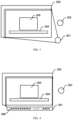
- FIG. 2 to FIG. 4 schematically show an arrangement of components of a security inspection system with a radiation imaging and a radioactive material monitoring being converged at the same time according to an exemplary embodiment of the present disclosure, wherein a radiation source capable of generating an X-ray in a pulse mode is taken as an example for illustration.
- the security inspection system includes an X-ray source 101, a radioactive material monitoring component 102, an X-ray imaging detector 103 and a conveying device 104.
- the conveying device 104 is, for example, a conveyor belt used to convey a luggage or package object 105 to pass through a detection region of the security inspection system, as indicated by the arrow in the figure.
- the radioactive material monitoring component 102 detects radioactivity information of the luggage or package object 105
- the X-ray source 101 emits an X-ray to irradiate or scan the luggage or package object
- the X-ray imaging detector 103 detects a ray emitted or generated by the luggage or package object 105 under an irradiation of the X-ray, wherein the ray is for example a radiation reflected, scattered or transmitted by the luggage or package object 105, so that X-ray imaging data may be obtained.
- the X-ray imaging detector 103 is arranged opposite to the X-ray source 101 to ensure that an effective X-ray scanning range may completely cover the detection region and a ray emitted (for example, reflected, scattered or transmitted) by the luggage or package object may be received.
- the radioactive material monitoring and the X-ray imaging of the luggage or package object are achieved.
- respective operations of the radioactive material monitoring subsystem and the X-ray imaging subsystem are performed alternately without an interference to each other, so that there is no restriction on an arrangement of the radioactive material monitoring component and the X-ray imaging component.
- the radioactive material monitoring component is, for example, a radioactivity monitoring detector, and may be arranged adjacent to the X-ray imaging component (such as the X-ray source 101) without isolation or shielding. Alternatively, they may also be arranged in a same cross section.
- FIG. 3 shows an arrangement of components of a security inspection system with a radiation imaging and a radioactive material monitoring being converged at the same time according to another exemplary embodiment of the present disclosure.
- a single-target point X-ray source 201 is used to emit and scan an X-ray in a pulse mode in a fixed angle or in an angular range to irradiate a luggage or package object 205 conveyed by a conveying device 204 to pass through the inspection region.
- An X-ray imaging detector 203 is arranged substantially opposite to the X-ray source 201 along an emission direction of an X-ray, and for example, includes an detector array having an L-shaped cross section used to receive a ray from the luggage or package object 205 and produce imaging data for forming a radiation image of the luggage or package object 205.
- a radioactive material monitoring component 202 e.g., a radioactivity monitoring detector
- FIG. 4 shows an arrangement of components of a security inspection system for converging a radiation imaging and a radioactive material monitoring at the same time according to yet another exemplary embodiment of the present disclosure, wherein a multi-point X-ray source 301 is used.
- the multi-point X-ray source 301 is a distributed X-ray source having multiple target points 306, and may generate X-rays from multiple locations to irradiate or scan a luggage or package object 305 conveyed by a conveying device 304 to pass through the detection region.
- the time sequence of generating X-rays at each target point may be flexibly controlled.
- the arrangement of the target points of the X-ray source may be in a straight line segment as shown in FIG.
- the arrangement of the target points of the X-ray source is arranged in a direction forming a surrounding (or a surrounding in a certain angular range) of the detected object.
- An X-ray imaging detector 303 is arranged substantially opposite to the X-ray source 301 along an emission direction of an X-ray, and for example, includes a detector array having an L-shaped cross section used to receive a ray from the luggage or package object 305 and produce imaging data for forming a radiation image of the luggage or package object 305.
- a radioactive material monitoring component 202 may be arranged adjacent to the X-ray source 301, for example, in a same cross section, and start or operate in a pulse mode, for example, before or after the X-ray source 301 emits an X-ray, so as to detect radioactivity information of the luggage or package object 305.
- a multi-point X-ray source structure is used, so that a ray imaging subsystem may obtain a multi-view image or a three-dimensional image of a luggage or package object.
- the synchronization control subsystem serves as a bridge for coordination and cooperation of the radioactive material monitoring subsystem and the radiation imaging subsystem, and dynamically deploys the work of the two.
- the synchronization control subsystem may control the radiation imaging subsystem and the radioactive substance monitoring subsystem in real time through a variable and adjustable pulse to operate alternately.
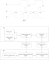
- FIG. 5 to FIG. 7 schematically show a working mode of a converged system for performing a radiation imaging and a radioactive material monitoring according to an exemplary embodiment of the present disclosure. As shown in FIG. 5 to FIG.
- the converged system or the synchronization subsystem may receive a trigger signal S1, and the trigger signal S1 may indicate the times when a luggage or package object enters and leave the detection region, so as to activate the radioactive material monitoring subsystem and the radiation imaging subsystem to work orderly.
- the trigger signal may be provided by a signal input and output control assembly, for example, a sensor or a trigger mechanism may be arranged along a path of conveying the luggage or package object to sense the times when the luggage or package object enters and leaves the detection region.
- object motion information is given according to a transporting operation of the conveying device to generate a trigger signal.
- the converged system further includes a transmission subsystem used to transport a luggage or package object to pass through the detection region, and including, for example, the above conveying device.
- the transmission subsystem may output a transmission signal indicating times when the luggage or package object enters and leaves the detection region and/or a transporting speed of the luggage or package object to the synchronization control subsystem, so that the synchronization control subsystem may control the radiation imaging subsystem and the radioactive material monitoring subsystem to operate based on the transmission signal.
- the radiation imaging subsystem and the radioactivity monitoring subsystem both work in a pulse mode under a deployment of the synchronization control subsystem.
- a working pulse has clear time information, and radioactivity information corresponding to a certain position or portion of the detected object may be clearly obtained in combination with the motion information of the detected object provided by the transmission subsystem.
- the transmission subsystem may include a conveying device (such as a conveyor belt or a belt conveying assembly), a transmission sensor assembly, and a transmission information output assembly.
- the conveying device includes a motor, a belt, a linkage component, etc., and carries a detected object to pass through a detection region.
- the transmission sensor assembly may include a speed sensor and a photoelectric gate sensor, etc., to monitor the working state of the transmission subsystem and provide signals of an object entering and leaving the detection region.
- the transmission information output assembly outputs the signals of an object entering and leaving the detection region and a moving speed of the detected object to the synchronization control subsystem.
- a low level of an S1 signal in the figure indicates that the luggage or package object has not entered or have not been detected to enter the detection region, and a rising edge indicates that the luggage or package object has begun to enter or will be detected to enter the detection region.
- a high level indicates that the luggage or package object has been transported to pass through the detection region, and a falling edge indicates that the luggage or package object has left the detection region or has been detected to leave the detection region.
- the radiation imaging subsystem may operate according to the first pulse control signal S2 to perform a radiation imaging on the luggage or package object, while the radioactive material monitoring subsystem may operate according to the second pulse control signal S3 to monitor whether the luggage or package object contains a radioactive material.
- the first pulse control signal or the second pulse control signal may include a rectangular wave (square wave).
- Each of the first pulse control signal and the second pulse control signal includes a plurality of pulses, and each pulse indicates that the corresponding radiation imaging subsystem and the radioactive material monitoring subsystem operate to perform a corresponding detection operation.
- the first pulse control signal S2 includes a plurality of first pulses S21 and indicates that the radiation imaging subsystem (e.g., the radiation source and the detector thereof) operates in this period to perform a radiation imaging operation on the luggage or package object that is passing through the detection region.
- the second pulse control signal S3 includes a second pulse S31, and the radioactive material monitoring subsystem operates in a period of the second pulse S31 to monitor a radioactive ray emitted by the luggage or package object. It may be seen that the first pulse S21 and the second pulse S31 are alternate in time sequence, and this ensures that the radiation imaging subsystem and the radioactive material monitoring subsystem work alternately according to the given pulse signals and according to the deployment of the synchronization control system without interfering with each other.
- the second pulse S31 appears after the first pulse S21, and this means that after the radiation imaging operation is performed, a radioactive ray emitted by the luggage or package object is detected by the radioactive material monitoring subsystem.
- the second pulse appears before the first pulse, and this means that the radioactive material monitoring is performed first, and then the radiation imaging operation is performed, thereby further avoiding an interference or an influence of the radiation imaging with or on the radioactive material monitoring.
- the radioactive material monitoring subsystem may measure environmental background radioactive data (in a period of the pulse S30). In the embodiment of FIG.
- the radioactive material monitoring subsystem may measure the environmental background radioactive data before each detection of a radioactive ray of a luggage or package object. After a detected object enters the detection region and the trigger signal S1 appears, the radiation imaging subsystem and the radioactive material monitoring subsystem work alternately according to the given pulse signals and according to the deployment of the synchronization control subsystem.
- a pulse width and a pulse frequency of each pulse may be adjusted according to requirements.
- each of some or all of the second pulses is located between two adjacent first pulses in time, and a distance between adjacent first pulses is greater than or equal to a pulse width of the second pulse.
- the converged system further includes an information converging subsystem configured to be in communication with the radioactive material monitoring subsystem and the radiation imaging subsystem to converge a radioactivity information of the luggage or package object obtained by the radioactive material monitoring subsystem into the image of the luggage or package object obtained by the radiation imaging subsystem, thereby accurately and more intuitively determining a position of a radioactive material on the luggage or package object may, or acquiring a converged image of a distribution of the radioactive material contained in the luggage or package object.
- the information converging subsystem may also be implemented by various suitable hardware/software.
- the information converging subsystem and the synchronization control subsystem may also be arranged separately, or they may be located in a same control system or controller, for example, they may be different modules in a same control system or controller.
- the information converging subsystem may include an image converging assembly and an alert information assembly.
- the image converging assembly performs a converging processing on the image or radiation data of the detected object obtained by the radiation imaging subsystem and the radioactivity information data of the detected object output by the radioactivity information output assembly in an image domain to obtain image information of the detected object with radioactivity information.
- the alarm information assembly may determine whether the detected object contains a dangerous and prohibited article according to the obtained image or radiation data of the detected object, and at the same time judge whether the detected object contains a radioactive material according to the radioactivity information of the detected object output by the radioactivity information output assembly. An appropriate alarm display and action are made according to the above judgment information.
- FIG. 8 shows an arrangement of a security inspection system with a radiation imaging and a radioactive material monitoring being converged according to a specific example of the present disclosure.
- the security inspection system includes a radiation imaging subsystem 10, a radioactive material monitoring subsystem 20 as well as a synchronization control subsystem 30 and an information converging subsystem 40 which are in communication with both the radiation imaging subsystem 10 and the radioactive material monitoring subsystem 20.
- the radiation imaging subsystem 10 includes a radiation source 11, a radiation imaging detector 12, a radiation imaging control assembly 13 and an imaging output assembly 14.
- the radiation imaging control assembly 13 controls the radiation source 11 and the radiation imaging detector 12 to operate in a pulse mode to acquire radiation imaging data of a luggage or package object.
- the imaging output assembly 14 may output a radiation imaging data signal of the luggage or package object, such as a radiation image.
- the radioactive material monitoring subsystem 20 includes a radioactivity monitoring detector 21, a radioactive material monitoring control assembly 23 and a radioactivity information output assembly 24.
- the synchronization control subsystem 30 may respectively control the radiation imaging subsystem 10 and the radioactive material monitoring subsystem 20 to operate in a pulse mode through the radiation imaging control assembly 13 and the radioactive material monitoring control assembly 23, for example, by providing pulse signals to the radiation imaging control assembly 13 and the radioactive material monitoring control assembly 23.
- the information converging subsystem 40 acquires output information of the imaging output assembly 14 and the radioactivity information output assembly 24, and converges the radioactivity information of the luggage or package object obtained by the radioactive material monitoring subsystem in the radiation image of the luggage or package object obtained by the radiation imaging subsystem.
- the embodiments of the present disclosure further relate to a method for performing a radiation imaging and a radioactive material monitoring using the above converged system.
- the method includes the following steps:
- a radiation beam may be generated by a radiation source (e.g., a low-energy X-ray source capable of a controllable pulse emission) in a pulse mode to irradiate the luggage or package object, and at the same time, a ray emitted or generated by the luggage or package object under an irradiation of the radiation beam is detected by a radiation imaging detector to generate data for forming an image of the luggage or package object.
- a radiation source e.g., a low-energy X-ray source capable of a controllable pulse emission
- a radioactivity monitoring detector may be operated in the pulse mode to monitor a radioactive ray emitted by the luggage or package object, such as a gamma ray or a neutron ray.
- the radiation imaging subsystem and the radioactive material monitoring subsystem may be controlled in real time to operate alternately by the synchronization control subsystem through a variable and adjustable pulse control signal.
- the radiation imaging subsystem is controlled to operate according to a first pulse control signal to perform the radiation imaging on the luggage or package object
- the radioactive material monitoring subsystem is controlled to operate according a second pulse control signal to monitor whether the luggage or package object contains a radioactive material
- the first pulse control signal or the second pulse control signal includes, for example, a rectangular wave.
- the first pulse control signal includes a plurality of first pulses
- the radiation imaging subsystem operates in a period of each first pulse.
- the second pulse control signal includes one or more second pulses staggered from the first pulses in time sequence, and the radioactive material monitoring subsystem operates in a period of each second pulse to monitor a radioactive ray emitted by the luggage or package object.
- each of some or all of the second pulses is between two adjacent first pulses in time, and a spacing between adjacent first pulses is greater than or equal to a pulse width of the second pulses.
- the luggage or package object may also be transported to pass through a detection region, and a transmission signal indicating times when the luggage or package object enters and leaves the detection region and a transporting speed of the luggage or package object may be output to at least the synchronization control subsystem, and operations of the radiation imaging subsystem and the radioactive material monitoring subsystem may be controlled by the synchronization control subsystem based on the transmission signal.
- the method further includes: converging a radioactivity information of the luggage or package object obtained by the radioactive material monitoring subsystem into the image of the luggage or package object obtained by the radiation imaging subsystem.
- FIG. 9 is a flowchart showing a method for converging a radiation imaging and a radioactive material monitoring according to a specific example of the present disclosure. As shown in the figure, the method includes the following steps:
- a radioactive material monitoring subsystem and a radiation imaging subsystem operable in a pulse mode under a regulation of a synchronization control subsystem a cooperative work of meeting an imaging and a radioactive material monitoring is achieved, the device occupation space is saved, the costs caused by an additional shielding are reduced, the number of an object circulation and transportation is reduced, the number of an object detection is reduced, the time of an object detection is reduced, and the speed of an object detection is increased.
- an converging of a radiation image and radioactivity monitoring data of a detected object is achieved, so that image information and radioactivity information may be displayed more intuitively. This may intuitively guide a further detection of a suspicious object, and may significantly improve the detection efficiency of objects.
- the operations may be implemented to be program modules or functional processes.
- the program modules or functional processes include systems, programs, programming, objects, components, data structures, etc., implement specific tasks or implement specific abstract data type, and may be executable using existing hardware.
- Such existing hardware may include one or more central processing units (CPUs), digital signal processors (DSPs), application specific integrated circuits, field programmable gate arrays (FPGAs), and the like.
- the present disclosure includes devices for performing one or more functions of methods, steps, operations or modules described in the present disclosure. These devices may be specially designed and manufactured for required purposes, or they may include known devices in general purpose computers. These devices have computer programs stored therein. These computer programs are selectively activated or reconfigured. Such computer programs may be stored in a device (e.g., computer) readable medium or stored in a medium of any type applicable for storing electronic instructions and respectively coupled to a bus.
- a device e.g., computer
- the computer readable medium includes but not limited to a disk of any type (including a floppy disk, a hard disk, an optical disk, a CD-ROM, and a magneto-optical disk), ROM (Read-Only Memory), RAM (Random Access Memory), EPROM (Erasable Programmable Read-Only Memory), EEPROM (Electrically Erasable Programmable Read-Only Memory), a flash memory, a magnetic card or an optical card. That is, a readable medium includes any medium storing or transmitting information in a device (e.g., a computer) readable manner.
Landscapes
- Physics & Mathematics (AREA)
- General Physics & Mathematics (AREA)
- Life Sciences & Earth Sciences (AREA)
- High Energy & Nuclear Physics (AREA)
- Health & Medical Sciences (AREA)
- Geophysics (AREA)
- General Life Sciences & Earth Sciences (AREA)
- Immunology (AREA)
- General Health & Medical Sciences (AREA)
- Pathology (AREA)
- Biochemistry (AREA)
- Analytical Chemistry (AREA)
- Chemical & Material Sciences (AREA)
- Molecular Biology (AREA)
- Spectroscopy & Molecular Physics (AREA)
- Analysing Materials By The Use Of Radiation (AREA)
Abstract
Description
- This application claims priority to
Chinese patent Application No. 202010578035.9, filed on June 23, 2020 - Embodiments of the present disclosure generally relate to a field of security inspection of a luggage or package object, and in particular, to a system and a method capable of integrating a radiation imaging and a radioactive substance monitoring.
- The radioactive material monitoring has been widely used in customs, borders, nuclear power stations and other places for entrance and exit detections to fight against an illegal transfer and transportation of radioactive materials and prevent a risk of radioactive material proliferation. In the existing radioactive material monitoring technology, a gamma ray or a neutron ray emitted by a radioactive material is mainly detected to identify whether a radioactive material is contained.
- The X-ray imaging technology has a wide range of important applications in the field of security inspection, medical diagnosis, industrial non-destructive testing, etc. It may efficiently detect dangerous explosives, flammable and corrosive materials or other dangerous and contraband goods hidden in objects through visual images in application scenarios such as customs ports, civil aviation logistics, and railway transportation.
- The radioactive material monitoring technology and the X-ray imaging technology have many overlapping portions in application scenarios. In entrance and exit detection places such as customs and borders, due to the needs of detection, it is not uncommon that radioactive material monitoring devices and X-ray imaging devices exist at the same time. However, limited by the interference of the detection principles of the two technologies, an X-ray emitted in an X-ray imaging will interfere with a radioactive material monitoring, and the two may not be performed at the same time.
- In the field of luggage or package security inspection imaging, a low energy X-ray source based on a hot cathode is often used. In this kind of X-ray source, electrons are emitted by heating a filament, and an anode target is bombarded under an action of an accelerating electric field to generate an X-ray. In this traditional X-ray source, a period of heating time, usually hundreds of milliseconds, is required from heating the filament to emitting electrons to generate an X-ray. As a result, generation of an X-ray is not immediate, and it usually takes hundreds of milliseconds to several seconds to work again if an interruption occurs. Based on the characteristic that the generation of such an X-ray requires a certain delay, an X-ray source usually works continuously. A commonly used low-energy X-ray imaging device needs to continuously generate X-rays, and this inevitably causes radiation interferences to a radioactive material monitoring device, makes it impossible for the radioactive monitoring device to effectively distinguish whether radioactive information comes from a detected object or from the X-ray imaging device.
- Traditionally, a radioactive material monitoring device and an X-ray imaging device are usually arranged separately, or they are arranged adjacent to each other after a shielding is added, or a limited converging is made in the accelerator light source imaging technology. An additional transitional space is required to arrange the two types of devices separately, and this will increase the number and time of the object detection and reduce the efficiency of the object detection. Arranging the two types of devices adjacent to each other after a shielding is added solves the problem, but the additional shielding structure brings additional space requirements, increases partial costs, and greatly limits the arrangement flexibility of radioactive material monitoring components. At the same time, the radioactive information of the detected object and the X-ray image information of the detected object are not dynamically integrated, and as a result the improvement of the detection efficiency of an object is limited.
- In some conventional methods, the accelerator light source imaging technology is converged with the radioactive material monitoring to some extent to achieve the radiation imaging inspection and the radioactive material monitoring. However, this method is limited by the application scope of the accelerator light source and may not be used in an application such as an ordinary luggage security inspection. An accelerator X-ray source usually produces an X-ray having a high energy, often in a magnitude of megaelectron volts, is mostly used in the field of imaging of large-scale cargos and vehicles, and is often seen at circulation gates of large-scale cargos and vehicles in customs, borders, etc. Due to the high energy and strong penetrating power of the X-ray, a high safety protection is required during a normal operation. Moreover, the volume of the device is large, and the overall floor area is large. In the field of luggage or package imaging inspection, considering that inspection objects are luggage and packages, an X-ray energy is required to be in a magnitude of kiloelectron volts. At the same time, considering that the application scenarios are customs, airports, subways, large-scale events, and other sensitive places for a luggage or package object security inspection, the security protection requirements for the overall device are high, the device needs to occupy a small area and is convenient for deployment. That is, an accelerator light source is not applicable for a radiation imaging in the field of luggage and package imaging inspection.
- The present disclosure is provided in order to overcome at least one of the above and other problems and defects in the related art.
- According to an aspect of the present disclosure, there is provided a converged system for performing a radiation imaging and a radioactive material monitoring on a luggage or package object, including: a radiation imaging subsystem configured to operate in a pulse mode to perform a radiation imaging on the luggage or package object; a radioactive material monitoring subsystem configured to operate in a pulse mode to monitor whether the luggage or package object contains a radioactive material; and a synchronization control subsystem being in communication with both the radiation imaging subsystem and the radioactive material monitoring subsystem, and configured to control the radiation imaging subsystem and the radioactive material monitoring subsystem to operate alternately.
- In some embodiments, the radiation imaging subsystem includes: a radiation source configured to generate a radiation beam in a pulse mode for irradiating the luggage or package object; and a radiation imaging detector configured to detect a ray emitted or generated by the luggage or package object under an irradiation of the radiation beam, so as to generate data for forming an image of the luggage or package object.
- In some embodiments, the radiation source is a low-energy X-ray source capable of a controllable pulse emission, especially a fast-pulse low-energy X-ray source capable of a fast pulse emission switching between tens of microseconds and tens of milliseconds. The ray source includes an X-ray source generating a cathode electron by pulsing, such as an X-ray source based on a carbon nanotube cathode and a hot cathode X-ray source having a grid control gate. The ray source may also include a pulse X-ray source of a single target and a pulse distributed X-ray source of multiple targets.
- In some embodiments, the radioactive material monitoring subsystem includes a radioactivity monitoring detector configured to operate in a pulse mode to monitor a radioactive ray emitted by the luggage or package object.
- In some embodiments, the radioactivity monitoring detector includes at least one of a gamma ray detector and a neutron detector.
- In some embodiments, the synchronization control subsystem is configured to control the radiation imaging subsystem and the radioactive material monitoring subsystem to operate alternately in real time through a variable and adjustable pulse control signal.
- In some embodiments, the radiation imaging subsystem is configured to operate according to a first pulse control signal to perform the radiation imaging on the luggage or package object, the radioactive material monitoring subsystem is configured to operate according a second pulse control signal to monitor whether the luggage or package object contains a radioactive material, and the first pulse control signal and the second pulse control signal include rectangular waves.
- In some embodiments, the first pulse control signal includes a plurality of first pulses, the second pulse control signal includes second pulses, the radioactive material monitoring subsystem being configured to operate during the second pulses to monitor a radioactive ray emitted by the luggage or package object, and each of some or all of the second pulses is between two adjacent first pulses in time, and a spacing between adjacent first pulses is greater than or equal to a pulse width of the second pulses.
- In some embodiments, the converged system further includes: a transmission subsystem configured to transport the luggage or package obj ect to pass through a detection region, and output a transmission signal indicating times when the luggage or package object enters and leaves the detection region and a transporting speed of the luggage or package object to at least the synchronization control subsystem, wherein the synchronization control subsystem is further configured to control operations of the radiation imaging subsystem and the radioactive material monitoring subsystem based on the transmission signal. For example, in the radiation imaging subsystem and the radioactive material monitoring subsystem described above, a fast switching within a short period between tens of microseconds to tens of milliseconds may be achieved through a fast pulse, so that X-ray perspective imaging information of the detected object and radioactive ray intensity information of the detected object may be acquired quickly and alternately during an uniform or continuous transporting process (without pausing or waiting) of the transmission subsystem.
- In some embodiments, the converged system further includes: an information converging subsystem configured to be in communication with the radioactive material monitoring subsystem and the radiation imaging subsystem, so as to converge a radioactivity information of the luggage or package object obtained by the radioactive material monitoring subsystem into the image of the luggage or package object obtained by the radiation imaging subsystem.
- According to another aspect of the present disclosure, there is provided a method for performing a radiation imaging and a radioactive material monitoring on a luggage or package object, including: operating a radiation imaging subsystem in a pulse mode to perform a radiation imaging on the luggage or package object; operating a radioactive material monitoring subsystem in a pulse mode to monitor whether the luggage or package object contains a radioactive material; and controlling the radiation imaging subsystem and the radioactive material monitoring subsystem to operate alternately by a synchronization control subsystem.
- In some embodiments, the operating a radiation imaging subsystem in a pulse mode to perform a radiation imaging on the luggage or package object includes: generating a radiation beam in a pulse mode to irradiate the luggage or package object by a low-energy X-ray source capable of a controllable pulse emission; and detecting a ray emitted or generated by the luggage or package object under an irradiation of the radiation beam to generate data for forming an image of the luggage or package object by a radiation imaging detector.
- In some embodiments, the operating a radioactive material monitoring subsystem in the pulse mode to monitor whether the luggage or package object contains a radioactive material includes: operating a radioactivity monitoring detector in a pulse mode to monitor a radioactive ray emitted by the luggage or package object.
- In some embodiments, at least one of a gamma ray and a neutron ray emitted by the luggage or package object is monitored by the radioactivity monitoring detector.
- In some embodiments, the radiation imaging subsystem and the radioactive material monitoring subsystem are controlled in real time to operate alternately by the synchronization control subsystem through a variable and adjustable pulse control signal.
- In some embodiments, the radiation imaging subsystem is controlled to operate according to a first pulse control signal to perform the radiation imaging on the luggage or package object, the radioactive material monitoring subsystem is controlled to operate according a second pulse control signal to monitor whether the luggage or package object contains a radioactive material, and the first pulse control signal and the second pulse control signal include rectangular waves.
- In some embodiments, the first pulse control signal includes a plurality of first pulses, the second pulse control signal includes second pulses, the radioactive material monitoring subsystem operating during the second pulses to monitor a radioactive ray emitted by the luggage or package object, and each of some or all of the second pulses is between two adjacent first pulses in time, and a spacing between adjacent first pulses is greater than or equal to a pulse width of the second pulses.
- In some embodiments, the method further includes: transporting the luggage or package object to pass through a detection region, and outputting a transmission signal indicating times when the luggage or package object enters and leaves the detection region and a transporting speed of the luggage or package object to at least the synchronization control subsystem by a transmission subsystem, and controlling operations of the radiation imaging subsystem and the radioactive material monitoring subsystem by the synchronization control subsystem based on the transmission signal.
- In some embodiments, the method further includes: converging a radioactivity information of the luggage or package object obtained by the radioactive material monitoring subsystem into the image of the luggage or package object obtained by the radiation imaging subsystem.
- Other objectives and advantages of the present disclosure will be apparent from the following detailed description of the present disclosure with reference to the accompanying drawings, and may help a comprehensive understanding of the present disclosure.
- The features and advantages of the present disclosure may be more clearly understood by referring to the accompanying drawings, and the accompanying drawings are schematic and should not be construed as limiting the present disclosure in any way, in which:
-
FIG. 1 is a block diagram showing an arrangement of a converged system for performing a radiation imaging and a radioactive material monitoring according to exemplary embodiments of the present disclosure; -
FIG. 2 is a side view showing an arrangement of a converged system for performing a radiation imaging and a radioactive material monitoring according to an exemplary embodiment of the present disclosure; -
FIG. 3 is a side view showing an arrangement of a converged system for performing a radiation imaging and a radioactive material monitoring according to another exemplary embodiment of the present disclosure; -
FIG. 4 is a side view showing an arrangement of a converged system for performing a radiation imaging and a radioactive material monitoring according to yet another exemplary embodiment of the present disclosure; -
FIG. 5 is a sequence diagram showing a working mode of a converged system for performing a radiation imaging and a radioactive material monitoring according to an exemplary embodiment of the present disclosure; -
FIG. 6 is a sequence diagram showing a working mode of a converged system for performing a radiation imaging and a radioactive material monitoring according to another exemplary embodiment of the present disclosure; -
FIG. 7 is a sequence diagram showing a working mode of a converged system for performing a radiation imaging and a radioactive material monitoring according to yet another exemplary embodiment of the present disclosure; -
FIG. 8 is a block diagram showing an arrangement of a converged system for performing a radiation imaging and a radioactive material monitoring according to an exemplary embodiment of the present disclosure; and -
FIG. 9 is a flowchart showing a method for performing a radiation imaging and a radioactive material monitoring according to an example of the present disclosure. - The technical solutions in the embodiments of the present disclosure will be clearly and completely described below in combination with the accompanying drawings in the embodiments of the present disclosure. Obviously, the described embodiments are only a portion of the embodiments of the present disclosure, not all of the embodiments. Based on the embodiments in the present disclosure, all the other embodiments obtained by those of ordinary skill in the art without any creative effort belong to the protection scope of the present disclosure.
- Additionally, in the following detailed description, for the purpose of explanation, numerous specific details are set forth in order to provide a thorough understanding of the embodiments of the present disclosure. It may be obvious, however, that one or more embodiments may be implemented without these specific details. In other instances, commonly known structures and devices are shown in diagram to simplify the drawings.
-
FIG. 1 schematically shows an arrangement of a converged system for performing a radiation imaging and a radioactive material monitoring according to an exemplary embodiment of the present disclosure. The converged system is deployed in sites such as customs, airports, subways, stations, and public places, so as to perform a security inspection on a luggage or package object carried by a person or transported through an express delivery. The converged system includes aradiation imaging subsystem 10, a radioactivematerial monitoring subsystem 20 and asynchronization control subsystem 30. Theradiation imaging subsystem 10 may operate in a pulse mode or in a discontinuous mode (e.g., be activated or operate intermittently) to perform a radiation imaging, such as a low energy radiation imaging, on the luggage or package object, and it may include, for example, an X-ray imaging system. It will be understood that "low energy" or "low energy radiation imaging" described herein is mentioned relative to a high energy radiation source such as an accelerator source, and is applicable for a radiation imaging, such as a radiation imaging having an X-ray energy in a magnitude of kiloelectron volts (kev), of a luggage or package object in the above locations. - The radioactive
material monitoring subsystem 20 may also operate in a pulse mode or in a discontinuous mode to monitor whether the luggage or package object contains a radioactive material. Thesynchronization control subsystem 30 is in communication with theradiation imaging subsystem 10 and the radioactivematerial monitoring subsystem 20, and controls the radiation imaging subsystem and the radioactive material monitoring subsystem to operate alternately, so as to perform a radiation imaging and a radioactive material monitoring on a same luggage or package object, thereby improving the detection efficiency. In this way, a radiation imaging operation will not affect or interfere with a radioactive material monitoring operation, and the radiation imaging subsystem and the radioactive material monitoring subsystem may be arranged adjacent to each other or arranged in a compact manner without an additional shielding structure being arranged therebetween, thereby reducing the costs and improving the flexibility in arrangement of system components. - In the embodiments of the present disclosure, the synchronization control subsystem is used to coordinate (e.g., in time sequence) operations of both the radiation imaging subsystem and the radioactive material monitoring subsystem, and ensure that the operations of the two do not interfere with each other. Exemplarily, the synchronization control subsystem may be implemented by various suitable hardware/software, including various controllers, control modules or application programs. For example, they may be converged in an inspection operating stage, converged in a control mechanism of the radiation imaging subsystem and/or the radioactive material monitoring subsystem, or arranged separately. The present disclosure does not specifically limit thereto.
- According to an exemplary embodiment of the present disclosure, the radiation imaging subsystem at least includes a radiation source and a radiation imaging detector. The radiation source generates a radiation beam in a pulse mode or in an intermittent mode for irradiating the luggage or package object, and the radiation imaging detector detects a ray emitted or generated (e.g., scattered, reflected or transmitted) by the luggage or package object under an irradiation of the radiation beam to generate data, such as an electrical signal, for forming an image of the luggage or package object. The radiation source includes a low-energy X-ray source capable of a controllable pulse emission, especially a fast-pulse low-energy X-ray source capable of a fast pulse emission switching between tens of microseconds and tens of milliseconds. The ray source includes an X-ray source generating a cathode electron by pulsing. As an example, the radiation source may be an X-ray source based on a carbon nanotube cathode or a hot cathode X-ray source having a grid control gate or any other suitable ray source operable in a pulse mode. For example, an X-ray source based on a carbon nanotube cathode is taken as an example. Under an action of a high voltage, a pulsed X-ray may be obtained by controlling the carbon nanotube cathode to emit electrons in a pulsed manner or in an intermittent manner to bombard an anode target. Thanks to the field electron emission characteristics of the carbon nanotube cathode, after a suitable field emission electric field is applied, electrons may be emitted instantaneously, for example, in less than a microsecond, and after the field emission electric field is removed, the emission of electrons may be stopped immediately. Such characteristic of instantaneous emission and stop of electrons enables an X-ray source to generate or stop an X-ray orderly according to the control pulse, for example, under an action of a control pulse of a control assembly.
- In the embodiments of the present disclosure, the radioactive material monitoring subsystem at least includes a radioactivity monitoring detector operable in a pulse mode to monitor a radioactive ray emitted from the luggage or package object itself or a radioactive material contained therein. For example, the radioactivity monitoring detector may include a gamma ray detector, a neutron detector, or both of them.
-
FIG. 2 to FIG. 4 schematically show an arrangement of components of a security inspection system with a radiation imaging and a radioactive material monitoring being converged at the same time according to an exemplary embodiment of the present disclosure, wherein a radiation source capable of generating an X-ray in a pulse mode is taken as an example for illustration. In the embodiment ofFIG. 2 , the security inspection system includes anX-ray source 101, a radioactivematerial monitoring component 102, anX-ray imaging detector 103 and a conveyingdevice 104. The conveyingdevice 104 is, for example, a conveyor belt used to convey a luggage orpackage object 105 to pass through a detection region of the security inspection system, as indicated by the arrow in the figure. In the process that the luggage orpackage object 105 passes through the detection region, the radioactivematerial monitoring component 102 detects radioactivity information of the luggage orpackage object 105, theX-ray source 101 emits an X-ray to irradiate or scan the luggage or package object, theX-ray imaging detector 103 detects a ray emitted or generated by the luggage orpackage object 105 under an irradiation of the X-ray, wherein the ray is for example a radiation reflected, scattered or transmitted by the luggage orpackage object 105, so that X-ray imaging data may be obtained. Exemplarily, theX-ray imaging detector 103 is arranged opposite to theX-ray source 101 to ensure that an effective X-ray scanning range may completely cover the detection region and a ray emitted (for example, reflected, scattered or transmitted) by the luggage or package object may be received. - Through a regulation of the synchronization control subsystem, in the process that the object passes through the detection region, in a pulse working mode, the radioactive material monitoring and the X-ray imaging of the luggage or package object are achieved. Under the regulation of the synchronization control subsystem, respective operations of the radioactive material monitoring subsystem and the X-ray imaging subsystem are performed alternately without an interference to each other, so that there is no restriction on an arrangement of the radioactive material monitoring component and the X-ray imaging component. The radioactive material monitoring component is, for example, a radioactivity monitoring detector, and may be arranged adjacent to the X-ray imaging component (such as the X-ray source 101) without isolation or shielding. Alternatively, they may also be arranged in a same cross section.
-
FIG. 3 shows an arrangement of components of a security inspection system with a radiation imaging and a radioactive material monitoring being converged at the same time according to another exemplary embodiment of the present disclosure. A single-targetpoint X-ray source 201 is used to emit and scan an X-ray in a pulse mode in a fixed angle or in an angular range to irradiate a luggage orpackage object 205 conveyed by a conveyingdevice 204 to pass through the inspection region. AnX-ray imaging detector 203 is arranged substantially opposite to theX-ray source 201 along an emission direction of an X-ray, and for example, includes an detector array having an L-shaped cross section used to receive a ray from the luggage orpackage object 205 and produce imaging data for forming a radiation image of the luggage orpackage object 205. A radioactive material monitoring component 202 (e.g., a radioactivity monitoring detector) may be arranged adjacent to theX-ray source 201, for example, in a same cross section, and start or operate in a pulse mode, for example, before or after theX-ray source 201 emits an X-ray, so as to detect radioactivity information of the luggage orpackage object 205. -
FIG. 4 shows an arrangement of components of a security inspection system for converging a radiation imaging and a radioactive material monitoring at the same time according to yet another exemplary embodiment of the present disclosure, wherein amulti-point X-ray source 301 is used. Themulti-point X-ray source 301 is a distributed X-ray source having multiple target points 306, and may generate X-rays from multiple locations to irradiate or scan a luggage orpackage object 305 conveyed by a conveyingdevice 304 to pass through the detection region. The time sequence of generating X-rays at each target point may be flexibly controlled. The arrangement of the target points of the X-ray source may be in a straight line segment as shown inFIG. 4 , or a broken line segment, an arc segment, or a combination thereof. The arrangement of the target points of the X-ray source is arranged in a direction forming a surrounding (or a surrounding in a certain angular range) of the detected object. AnX-ray imaging detector 303 is arranged substantially opposite to theX-ray source 301 along an emission direction of an X-ray, and for example, includes a detector array having an L-shaped cross section used to receive a ray from the luggage orpackage object 305 and produce imaging data for forming a radiation image of the luggage orpackage object 305. A radioactivematerial monitoring component 202 may be arranged adjacent to theX-ray source 301, for example, in a same cross section, and start or operate in a pulse mode, for example, before or after theX-ray source 301 emits an X-ray, so as to detect radioactivity information of the luggage orpackage object 305. A multi-point X-ray source structure is used, so that a ray imaging subsystem may obtain a multi-view image or a three-dimensional image of a luggage or package object. - The synchronization control subsystem serves as a bridge for coordination and cooperation of the radioactive material monitoring subsystem and the radiation imaging subsystem, and dynamically deploys the work of the two. For example, the synchronization control subsystem may control the radiation imaging subsystem and the radioactive substance monitoring subsystem in real time through a variable and adjustable pulse to operate alternately.
FIG. 5 to FIG. 7 schematically show a working mode of a converged system for performing a radiation imaging and a radioactive material monitoring according to an exemplary embodiment of the present disclosure. As shown inFIG. 5 to FIG. 7 , the converged system or the synchronization subsystem may receive a trigger signal S1, and the trigger signal S1 may indicate the times when a luggage or package object enters and leave the detection region, so as to activate the radioactive material monitoring subsystem and the radiation imaging subsystem to work orderly. The trigger signal may be provided by a signal input and output control assembly, for example, a sensor or a trigger mechanism may be arranged along a path of conveying the luggage or package object to sense the times when the luggage or package object enters and leaves the detection region. As an alternative or a supplement, object motion information is given according to a transporting operation of the conveying device to generate a trigger signal. - In some examples, the converged system further includes a transmission subsystem used to transport a luggage or package object to pass through the detection region, and including, for example, the above conveying device. The transmission subsystem may output a transmission signal indicating times when the luggage or package object enters and leaves the detection region and/or a transporting speed of the luggage or package object to the synchronization control subsystem, so that the synchronization control subsystem may control the radiation imaging subsystem and the radioactive material monitoring subsystem to operate based on the transmission signal. The radiation imaging subsystem and the radioactivity monitoring subsystem both work in a pulse mode under a deployment of the synchronization control subsystem. A working pulse has clear time information, and radioactivity information corresponding to a certain position or portion of the detected object may be clearly obtained in combination with the motion information of the detected object provided by the transmission subsystem.
- Exemplarily, the transmission subsystem may include a conveying device (such as a conveyor belt or a belt conveying assembly), a transmission sensor assembly, and a transmission information output assembly. The conveying device includes a motor, a belt, a linkage component, etc., and carries a detected object to pass through a detection region. The transmission sensor assembly may include a speed sensor and a photoelectric gate sensor, etc., to monitor the working state of the transmission subsystem and provide signals of an object entering and leaving the detection region. The transmission information output assembly outputs the signals of an object entering and leaving the detection region and a moving speed of the detected object to the synchronization control subsystem.
- For example, a low level of an S1 signal in the figure indicates that the luggage or package object has not entered or have not been detected to enter the detection region, and a rising edge indicates that the luggage or package object has begun to enter or will be detected to enter the detection region. A high level indicates that the luggage or package object has been transported to pass through the detection region, and a falling edge indicates that the luggage or package object has left the detection region or has been detected to leave the detection region.
- As shown in
FIG. 5 to FIG. 7 , the radiation imaging subsystem may operate according to the first pulse control signal S2 to perform a radiation imaging on the luggage or package object, while the radioactive material monitoring subsystem may operate according to the second pulse control signal S3 to monitor whether the luggage or package object contains a radioactive material. Exemplarily, the first pulse control signal or the second pulse control signal may include a rectangular wave (square wave). Each of the first pulse control signal and the second pulse control signal includes a plurality of pulses, and each pulse indicates that the corresponding radiation imaging subsystem and the radioactive material monitoring subsystem operate to perform a corresponding detection operation. For example, the first pulse control signal S2 includes a plurality of first pulses S21 and indicates that the radiation imaging subsystem (e.g., the radiation source and the detector thereof) operates in this period to perform a radiation imaging operation on the luggage or package object that is passing through the detection region. The second pulse control signal S3 includes a second pulse S31, and the radioactive material monitoring subsystem operates in a period of the second pulse S31 to monitor a radioactive ray emitted by the luggage or package object. It may be seen that the first pulse S21 and the second pulse S31 are alternate in time sequence, and this ensures that the radiation imaging subsystem and the radioactive material monitoring subsystem work alternately according to the given pulse signals and according to the deployment of the synchronization control system without interfering with each other. - In the embodiment of
FIG. 5 , the second pulse S31 appears after the first pulse S21, and this means that after the radiation imaging operation is performed, a radioactive ray emitted by the luggage or package object is detected by the radioactive material monitoring subsystem. In the embodiment ofFIG. 6 , the second pulse appears before the first pulse, and this means that the radioactive material monitoring is performed first, and then the radiation imaging operation is performed, thereby further avoiding an interference or an influence of the radiation imaging with or on the radioactive material monitoring. In addition, in a preparation stage, i.e., before the rising edge of the S1 signal, the radioactive material monitoring subsystem may measure environmental background radioactive data (in a period of the pulse S30). In the embodiment ofFIG. 7 , the radioactive material monitoring subsystem may measure the environmental background radioactive data before each detection of a radioactive ray of a luggage or package object. After a detected object enters the detection region and the trigger signal S1 appears, the radiation imaging subsystem and the radioactive material monitoring subsystem work alternately according to the given pulse signals and according to the deployment of the synchronization control subsystem. - A pulse width and a pulse frequency of each pulse may be adjusted according to requirements. Exemplarily, as shown in
FIG. 5 to FIG. 7 , each of some or all of the second pulses is located between two adjacent first pulses in time, and a distance between adjacent first pulses is greater than or equal to a pulse width of the second pulse. - According to some embodiments, the converged system further includes an information converging subsystem configured to be in communication with the radioactive material monitoring subsystem and the radiation imaging subsystem to converge a radioactivity information of the luggage or package object obtained by the radioactive material monitoring subsystem into the image of the luggage or package object obtained by the radiation imaging subsystem, thereby accurately and more intuitively determining a position of a radioactive material on the luggage or package object may, or acquiring a converged image of a distribution of the radioactive material contained in the luggage or package object. It may be understood that, similar to the synchronization control subsystem, the information converging subsystem may also be implemented by various suitable hardware/software. The information converging subsystem and the synchronization control subsystem may also be arranged separately, or they may be located in a same control system or controller, for example, they may be different modules in a same control system or controller.
- In some examples, the information converging subsystem may include an image converging assembly and an alert information assembly. The image converging assembly performs a converging processing on the image or radiation data of the detected object obtained by the radiation imaging subsystem and the radioactivity information data of the detected object output by the radioactivity information output assembly in an image domain to obtain image information of the detected object with radioactivity information. The alarm information assembly may determine whether the detected object contains a dangerous and prohibited article according to the obtained image or radiation data of the detected object, and at the same time judge whether the detected object contains a radioactive material according to the radioactivity information of the detected object output by the radioactivity information output assembly. An appropriate alarm display and action are made according to the above judgment information.
-
FIG. 8 shows an arrangement of a security inspection system with a radiation imaging and a radioactive material monitoring being converged according to a specific example of the present disclosure. As shown in the figure, the security inspection system includes aradiation imaging subsystem 10, a radioactivematerial monitoring subsystem 20 as well as asynchronization control subsystem 30 and aninformation converging subsystem 40 which are in communication with both theradiation imaging subsystem 10 and the radioactivematerial monitoring subsystem 20. Theradiation imaging subsystem 10 includes aradiation source 11, aradiation imaging detector 12, a radiationimaging control assembly 13 and animaging output assembly 14. The radiationimaging control assembly 13 controls theradiation source 11 and theradiation imaging detector 12 to operate in a pulse mode to acquire radiation imaging data of a luggage or package object. Theimaging output assembly 14 may output a radiation imaging data signal of the luggage or package object, such as a radiation image. The radioactivematerial monitoring subsystem 20 includes aradioactivity monitoring detector 21, a radioactive materialmonitoring control assembly 23 and a radioactivityinformation output assembly 24. Thesynchronization control subsystem 30 may respectively control theradiation imaging subsystem 10 and the radioactivematerial monitoring subsystem 20 to operate in a pulse mode through the radiationimaging control assembly 13 and the radioactive materialmonitoring control assembly 23, for example, by providing pulse signals to the radiationimaging control assembly 13 and the radioactive materialmonitoring control assembly 23. Theinformation converging subsystem 40 acquires output information of theimaging output assembly 14 and the radioactivityinformation output assembly 24, and converges the radioactivity information of the luggage or package object obtained by the radioactive material monitoring subsystem in the radiation image of the luggage or package object obtained by the radiation imaging subsystem. - The embodiments of the present disclosure further relate to a method for performing a radiation imaging and a radioactive material monitoring using the above converged system. The method includes the following steps:
- a radiation imaging subsystem is operated in a pulse mode to perform a radiation imaging on a luggage or package object; and
- a radioactive material monitoring subsystem is operated in a pulse mode to monitor whether the luggage or package object contains a radioactive material; wherein the radiation imaging subsystem and the radioactive material monitoring subsystem are controlled to operate alternately by a synchronization control subsystem.
- When a radiation imaging is performed on the luggage or package object, a radiation beam may be generated by a radiation source (e.g., a low-energy X-ray source capable of a controllable pulse emission) in a pulse mode to irradiate the luggage or package object, and at the same time, a ray emitted or generated by the luggage or package object under an irradiation of the radiation beam is detected by a radiation imaging detector to generate data for forming an image of the luggage or package object.
- When it is monitored whether the luggage or package object contains a radioactive material, a radioactivity monitoring detector may be operated in the pulse mode to monitor a radioactive ray emitted by the luggage or package object, such as a gamma ray or a neutron ray.
- In the operations, the radiation imaging subsystem and the radioactive material monitoring subsystem may be controlled in real time to operate alternately by the synchronization control subsystem through a variable and adjustable pulse control signal. Exemplarily, the radiation imaging subsystem is controlled to operate according to a first pulse control signal to perform the radiation imaging on the luggage or package object, the radioactive material monitoring subsystem is controlled to operate according a second pulse control signal to monitor whether the luggage or package object contains a radioactive material, and the first pulse control signal or the second pulse control signal includes, for example, a rectangular wave. In some examples, the first pulse control signal includes a plurality of first pulses, and the radiation imaging subsystem operates in a period of each first pulse. The second pulse control signal includes one or more second pulses staggered from the first pulses in time sequence, and the radioactive material monitoring subsystem operates in a period of each second pulse to monitor a radioactive ray emitted by the luggage or package object. As an example, each of some or all of the second pulses is between two adjacent first pulses in time, and a spacing between adjacent first pulses is greater than or equal to a pulse width of the second pulses.
- In this method, by a transmission subsystem, the luggage or package object may also be transported to pass through a detection region, and a transmission signal indicating times when the luggage or package object enters and leaves the detection region and a transporting speed of the luggage or package object may be output to at least the synchronization control subsystem, and operations of the radiation imaging subsystem and the radioactive material monitoring subsystem may be controlled by the synchronization control subsystem based on the transmission signal.
- In some embodiments, the method further includes: converging a radioactivity information of the luggage or package object obtained by the radioactive material monitoring subsystem into the image of the luggage or package object obtained by the radiation imaging subsystem.
-
FIG. 9 is a flowchart showing a method for converging a radiation imaging and a radioactive material monitoring according to a specific example of the present disclosure. As shown in the figure, the method includes the following steps: - S01: environmental background radioactivity data is measured by the radioactivity monitoring subsystem;
- S02: the luggage or package object enters the detection region, a trigger signal appears and the detection begins;
- S03: the luggage or package object is transported to pass through the detection region, at the same time, the radiation imaging subsystem and the radiation monitoring subsystem operate alternately;
- S04: a radiation image and radioactivity monitoring information of the luggage or package object are output; and
- S05: the luggage or package object leaves the detection region, and the detection ends.
- In the embodiments of the present disclosure, by using a radioactive material monitoring subsystem and a radiation imaging subsystem operable in a pulse mode under a regulation of a synchronization control subsystem, a cooperative work of meeting an imaging and a radioactive material monitoring is achieved, the device occupation space is saved, the costs caused by an additional shielding are reduced, the number of an object circulation and transportation is reduced, the number of an object detection is reduced, the time of an object detection is reduced, and the speed of an object detection is increased. At the same time, an converging of a radiation image and radioactivity monitoring data of a detected object is achieved, so that image information and radioactivity information may be displayed more intuitively. This may intuitively guide a further detection of a suspicious object, and may significantly improve the detection efficiency of objects.
- In the above description, illustrative embodiments have been described with reference to actions and symbolic representations (e.g., in the form of a flowchart) of operations. The operations may be implemented to be program modules or functional processes. The program modules or functional processes include systems, programs, programming, objects, components, data structures, etc., implement specific tasks or implement specific abstract data type, and may be executable using existing hardware. Such existing hardware may include one or more central processing units (CPUs), digital signal processors (DSPs), application specific integrated circuits, field programmable gate arrays (FPGAs), and the like.
- In the present text, unless specifically stated otherwise, or as apparent from the discussion, terms such as "process", "determine", "acquire", "obtain", "judge" and "control" refer to that operations or steps may be represented as data of physical electron quantities in a register and a memory of a computer system, and may be represented as actions and processes of a computer system or a similar electronic computing device converting them to be similarly represented as other data of physical quantities in a register or a memory of a computer system or another such device for information storage, transmission or display.
- Illustrative embodiments have been described above with reference to actions and symbolic representations (e.g., in the form of a flowchart) of operations of steps. The operations or steps may be implemented to be program modules or functional processes. The program modules or functional processes include systems, programs, programming, objects, components, data structures, etc., implement specific tasks or implement specific abstract data type, and may be executable using existing hardware.
- Those skilled in the art may understand that the present disclosure includes devices for performing one or more functions of methods, steps, operations or modules described in the present disclosure. These devices may be specially designed and manufactured for required purposes, or they may include known devices in general purpose computers. These devices have computer programs stored therein. These computer programs are selectively activated or reconfigured. Such computer programs may be stored in a device (e.g., computer) readable medium or stored in a medium of any type applicable for storing electronic instructions and respectively coupled to a bus. The computer readable medium includes but not limited to a disk of any type (including a floppy disk, a hard disk, an optical disk, a CD-ROM, and a magneto-optical disk), ROM (Read-Only Memory), RAM (Random Access Memory), EPROM (Erasable Programmable Read-Only Memory), EEPROM (Electrically Erasable Programmable Read-Only Memory), a flash memory, a magnetic card or an optical card. That is, a readable medium includes any medium storing or transmitting information in a device (e.g., a computer) readable manner.
- The embodiments of the present disclosure have been shown and described, but it will be understood by those skilled in the art that modifications may be made to these embodiments without departing from the principles and spirits of the present disclosure, and the scope of the present disclosure is defined by the appended claims and the equivalents thereof.
Claims (16)
- A converged system for performing a radiation imaging and a radioactive material monitoring on a luggage or package object, comprising:a radiation imaging subsystem configured to operate in a pulse mode to perform a radiation imaging on the luggage or package object;a radioactive material monitoring subsystem configured to operate in a pulse mode to monitor whether the luggage or package object contains a radioactive material; anda synchronization control subsystem being in communication with both the radiation imaging subsystem and the radioactive material monitoring subsystem, and configured to control the radiation imaging subsystem and the radioactive material monitoring subsystem to operate alternately,wherein the radiation imaging subsystem comprises:a radiation source configured to generate a radiation beam in a pulse mode for irradiating the luggage or package object; anda radiation imaging detector configured to detect a ray emitted or generated by the luggage or package object under an irradiation of the radiation beam, so as to generate data for forming an image of the luggage or package object,wherein the radiation source is a low-energy X-ray source capable of a controllable pulse emission, and the low-energy X-ray source is configured to perform a radiation imaging with an X-ray energy in a magnitude of kiloelectron volts on the luggage or package object.
- The converged system according to claim 1, wherein the radioactive material monitoring subsystem comprises a radioactivity monitoring detector configured to operate in a pulse mode to monitor a radioactive ray emitted by the luggage or package object.
- The converged system according to claim 2, wherein the radioactivity monitoring detector comprises at least one of a gamma ray detector and a neutron detector.
- The converged system according to any one of claims 1 and 3, wherein the synchronization control subsystem is configured to control the radiation imaging subsystem and the radioactive material monitoring subsystem to operate alternately in real time through a variable and adjustable pulse control signal.
- The converged system according to any one of claims 1 and 3, wherein,the radiation imaging subsystem is configured to operate according to a first pulse control signal to perform the radiation imaging on the luggage or package object,the radioactive material monitoring subsystem is configured to operate according a second pulse control signal to monitor whether the luggage or package object contains a radioactive material, andthe first pulse control signal and the second pulse control signal comprise rectangular waves.
- The converged system according to claim 5, wherein,the first pulse control signal comprises a plurality of first pulses,the second pulse control signal comprises second pulses, the radioactive material monitoring subsystem being configured to operate during the second pulses to monitor a radioactive ray emitted by the luggage or package object, andeach of some or all of the second pulses is between two adjacent first pulses in time, and a spacing between adjacent first pulses is greater than or equal to a pulse width of the second pulses.
- The converged system according to any one of claims 1, 3 and 6, further comprising:a transmission subsystem configured to transport the luggage or package object to pass through a detection region, and output a transmission signal indicating times when the luggage or package object enters and leaves the detection region and a transporting speed of the luggage or package object to at least the synchronization control subsystem,wherein the synchronization control subsystem is further configured to control operations of the radiation imaging subsystem and the radioactive material monitoring subsystem based on the transmission signal.
- The converged system according to any one of claims 1, 3 and 6, further comprising:
an information converging subsystem configured to be in communication with the radioactive material monitoring subsystem and the radiation imaging subsystem, so as to converge a radioactivity information of the luggage or package object obtained by the radioactive material monitoring subsystem into the image of the luggage or package object obtained by the radiation imaging subsystem. - A method for performing a radiation imaging and a radioactive material monitoring on a luggage or package object, comprising:operating a radiation imaging subsystem in a pulse mode to perform a radiation imaging on the luggage or package object;operating a radioactive material monitoring subsystem in a pulse mode to monitor whether the luggage or package object contains a radioactive material; andcontrolling the radiation imaging subsystem and the radioactive material monitoring subsystem to operate alternately by a synchronization control subsystem,wherein the operating a radiation imaging subsystem in a pulse mode to perform a radiation imaging on the luggage or package object comprises:generating a radiation beam in a pulse mode to irradiate the luggage or package object by a low-energy X-ray source being capable of a controllable pulse emission and having an X-ray energy in a magnitude of kiloelectron volts; anddetecting a ray emitted or generated by the luggage or package object under an irradiation of the radiation beam to generate data for forming an image of the luggage or package object by a radiation imaging detector.
- The method according to claim 9, wherein the operating a radioactive material monitoring subsystem in the pulse mode to monitor whether the luggage or package object contains a radioactive material comprises:
operating a radioactivity monitoring detector in a pulse mode to monitor a radioactive ray emitted by the luggage or package object. - The method according to claim 10, wherein at least one of a gamma ray and a neutron ray emitted by the luggage or package object is monitored by the radioactivity monitoring detector.
- The method according to any one of claims 9-11, wherein the radiation imaging subsystem and the radioactive material monitoring subsystem are controlled in real time to operate alternately by the synchronization control subsystem through a variable and adjustable pulse control signal.
- The method according to any one of claims 9-11, whereinthe radiation imaging subsystem is controlled to operate according to a first pulse control signal to perform the radiation imaging on the luggage or package object,the radioactive material monitoring subsystem is controlled to operate according a second pulse control signal to monitor whether the luggage or package object contains a radioactive material, andthe first pulse control signal and the second pulse control signal comprise rectangular waves.
- The method according to claim 13, whereinthe first pulse control signal comprises a plurality of first pulses,the second pulse control signal comprises second pulses, the radioactive material monitoring subsystem operating during the second pulses to monitor a radioactive ray emitted by the luggage or package object, andeach of some or all of the second pulses is between two adjacent first pulses in time, and a spacing between adjacent first pulses is greater than or equal to a pulse width of the second pulses.
- The method according to any one of claims 9-11 and 14, further comprising:transporting the luggage or package object to pass through a detection region, and outputting a transmission signal indicating times when the luggage or package object enters and leaves the detection region and a transporting speed of the luggage or package object to at least the synchronization control subsystem by a transmission subsystem, andcontrolling operations of the radiation imaging subsystem and the radioactive material monitoring subsystem by the synchronization control subsystem based on the transmission signal.
- The method according to any one of claims 9-11 and 14, further comprising:
converging a radioactivity information of the luggage or package object obtained by the radioactive material monitoring subsystem into the image of the luggage or package object obtained by the radiation imaging subsystem.
Applications Claiming Priority (2)
| Application Number | Priority Date | Filing Date | Title |
|---|---|---|---|
| CN202010578035.9A CN111487262A (en) | 2020-06-23 | 2020-06-23 | Fusion system and method for radiation imaging and radioactive material monitoring |
| PCT/CN2021/099356 WO2021259070A1 (en) | 2020-06-23 | 2021-06-10 | Fusion system and method for radiation imaging and radioactive material monitoring |
Publications (2)
| Publication Number | Publication Date |
|---|---|
| EP4170328A1 true EP4170328A1 (en) | 2023-04-26 |
| EP4170328A4 EP4170328A4 (en) | 2024-07-03 |
Family
ID=71811393
Family Applications (1)
| Application Number | Title | Priority Date | Filing Date |
|---|---|---|---|
| EP21828334.9A Pending EP4170328A4 (en) | 2020-06-23 | 2021-06-10 | FUSION SYSTEM AND METHODS FOR RADIATION IMAGING AND MONITORING RADIOACTIVE MATERIAL |
Country Status (3)
| Country | Link |
|---|---|
| EP (1) | EP4170328A4 (en) |
| CN (2) | CN111487262A (en) |
| WO (1) | WO2021259070A1 (en) |
Cited By (1)
| Publication number | Priority date | Publication date | Assignee | Title |
|---|---|---|---|---|
| WO2026013209A1 (en) * | 2024-07-10 | 2026-01-15 | Rapiscan Holdings, Inc. | Systems and methods for real-time detection and elimination of x-ray bursts in gamma radiation measurements |
Families Citing this family (2)
| Publication number | Priority date | Publication date | Assignee | Title |
|---|---|---|---|---|
| CN111487262A (en) * | 2020-06-23 | 2020-08-04 | 清华大学 | Fusion system and method for radiation imaging and radioactive material monitoring |
| CN114955318B (en) * | 2022-04-14 | 2024-08-16 | 福建纳仕达电子股份有限公司 | Circuit control method for induction trash can with cold cathode ultraviolet lamp for deodorization |
Family Cites Families (10)
| Publication number | Priority date | Publication date | Assignee | Title |
|---|---|---|---|---|
| US5838759A (en) * | 1996-07-03 | 1998-11-17 | Advanced Research And Applications Corporation | Single beam photoneutron probe and X-ray imaging system for contraband detection and identification |
| US20050105665A1 (en) * | 2000-03-28 | 2005-05-19 | Lee Grodzins | Detection of neutrons and sources of radioactive material |
| US7251310B2 (en) * | 2004-05-27 | 2007-07-31 | L-3 Communications Security And Detection System | Method and apparatus for detecting contraband using radiated compound signatures |
| CN101539556B (en) * | 2008-03-18 | 2012-08-08 | 同方威视技术股份有限公司 | Integrating system and integrating method for radioactive substance detection and X-ray radiation imaging |
| CN101561405B (en) * | 2008-04-17 | 2011-07-06 | 清华大学 | Straight-line track scanning imaging system and method |
| WO2011137504A1 (en) * | 2010-05-05 | 2011-11-10 | Nauchno-Proizvodstvennoe Chastnoe Uniternoe Predpriyatie Adani | Cargo and vehicle inspection system |
| CN103901493B (en) * | 2012-12-27 | 2016-12-28 | 同方威视技术股份有限公司 | A kind of no frame CT device |
| CN104374784B (en) * | 2014-11-05 | 2017-05-17 | 同方威视技术股份有限公司 | Detection system and method for synchronously positioning radioactive substances |
| PL3491427T3 (en) * | 2016-07-28 | 2026-05-11 | Smiths Detection France S.A.S. | Scatter imaging |
| CN111487262A (en) * | 2020-06-23 | 2020-08-04 | 清华大学 | Fusion system and method for radiation imaging and radioactive material monitoring |
-
2020
- 2020-06-23 CN CN202010578035.9A patent/CN111487262A/en active Pending
- 2020-06-23 CN CN202310037600.4A patent/CN116203050B/en active Active
-
2021
- 2021-06-10 EP EP21828334.9A patent/EP4170328A4/en active Pending
- 2021-06-10 WO PCT/CN2021/099356 patent/WO2021259070A1/en not_active Ceased
Cited By (1)
| Publication number | Priority date | Publication date | Assignee | Title |
|---|---|---|---|---|
| WO2026013209A1 (en) * | 2024-07-10 | 2026-01-15 | Rapiscan Holdings, Inc. | Systems and methods for real-time detection and elimination of x-ray bursts in gamma radiation measurements |
Also Published As
| Publication number | Publication date |
|---|---|
| CN111487262A (en) | 2020-08-04 |
| EP4170328A4 (en) | 2024-07-03 |
| CN116203050A (en) | 2023-06-02 |
| CN116203050B (en) | 2026-03-03 |
| WO2021259070A1 (en) | 2021-12-30 |
Similar Documents
| Publication | Publication Date | Title |
|---|---|---|
| KR102055963B1 (en) | Methods and systems for time-of-flight neutron interrogation for material descrimination | |
| US7742563B2 (en) | X-ray source and detector configuration for a non-translational x-ray diffraction system | |
| US7492862B2 (en) | Computed tomography cargo inspection system and method | |
| JP5037328B2 (en) | Two-energy radiation scanning of objects | |
| US20070237294A1 (en) | Method and apparatus for the safe and rapid detection of nuclear devices within containers | |
| US11921252B2 (en) | Security screening device capable of detecting and locating dangerous objects by using radiation | |
| US8137976B2 (en) | Dual angle radiation scanning of objects | |
| Bendahan | Vehicle and cargo scanning for contraband | |
| WO2021259070A1 (en) | Fusion system and method for radiation imaging and radioactive material monitoring | |
| KR102880859B1 (en) | Systems and methods for eliminating crosstalk signals in one or more scanning systems having multiple X-ray sources | |
| US9239303B2 (en) | Material discrimination system | |
| EP3491426B1 (en) | Inspection system with source of radiation and method | |
| US20160356915A1 (en) | Four plane x-ray inspection system | |
| Van Liew et al. | Identification and imaging of special nuclear materials and contraband using active x-ray interrogation | |
| KR20230123357A (en) | Security check apparatus using combined radiation | |
| HK40014937A (en) | Methods and systems for time-of-flight neutron interrogation for material descrimination | |
| Viesti | Status Report on the detection of illicit materials in cargo containers by using neutron beams. |
Legal Events
| Date | Code | Title | Description |
|---|---|---|---|
| STAA | Information on the status of an ep patent application or granted ep patent |
Free format text: STATUS: THE INTERNATIONAL PUBLICATION HAS BEEN MADE |
|
| PUAI | Public reference made under article 153(3) epc to a published international application that has entered the european phase |
Free format text: ORIGINAL CODE: 0009012 |
|
| STAA | Information on the status of an ep patent application or granted ep patent |
Free format text: STATUS: REQUEST FOR EXAMINATION WAS MADE |
|
| 17P | Request for examination filed |
Effective date: 20221223 |
|
| AK | Designated contracting states |
Kind code of ref document: A1 Designated state(s): AL AT BE BG CH CY CZ DE DK EE ES FI FR GB GR HR HU IE IS IT LI LT LU LV MC MK MT NL NO PL PT RO RS SE SI SK SM TR |
|
| DAV | Request for validation of the european patent (deleted) | ||
| DAX | Request for extension of the european patent (deleted) | ||
| REG | Reference to a national code |
Ref country code: DE Ref legal event code: R079 Free format text: PREVIOUS MAIN CLASS: G01N0023040000 Ipc: G01V0005220000 |
|
| A4 | Supplementary search report drawn up and despatched |
Effective date: 20240604 |
|
| RIC1 | Information provided on ipc code assigned before grant |
Ipc: G01V 5/00 20060101ALI20240528BHEP Ipc: G01N 23/04 20180101ALI20240528BHEP Ipc: G01V 5/26 20240101ALI20240528BHEP Ipc: G01V 5/22 20240101AFI20240528BHEP |
|
| GRAP | Despatch of communication of intention to grant a patent |
Free format text: ORIGINAL CODE: EPIDOSNIGR1 |
|
| STAA | Information on the status of an ep patent application or granted ep patent |
Free format text: STATUS: GRANT OF PATENT IS INTENDED |
|
| INTG | Intention to grant announced |
Effective date: 20260130 |