EP4170302B1 - Hyperspectral image sensor and operating method thereof - Google Patents
Hyperspectral image sensor and operating method thereof Download PDFInfo
- Publication number
- EP4170302B1 EP4170302B1 EP22188766.4A EP22188766A EP4170302B1 EP 4170302 B1 EP4170302 B1 EP 4170302B1 EP 22188766 A EP22188766 A EP 22188766A EP 4170302 B1 EP4170302 B1 EP 4170302B1
- Authority
- EP
- European Patent Office
- Prior art keywords
- sub
- partial region
- hyperspectral image
- spectrum
- region
- Prior art date
- Legal status (The legal status is an assumption and is not a legal conclusion. Google has not performed a legal analysis and makes no representation as to the accuracy of the status listed.)
- Active
Links
Images







Classifications
-
- G—PHYSICS
- G01—MEASURING; TESTING
- G01N—INVESTIGATING OR ANALYSING MATERIALS BY DETERMINING THEIR CHEMICAL OR PHYSICAL PROPERTIES
- G01N21/00—Investigating or analysing materials by the use of optical means, i.e. using sub-millimetre waves, infrared, visible or ultraviolet light
- G01N21/17—Systems in which incident light is modified in accordance with the properties of the material investigated
- G01N21/25—Colour; Spectral properties, i.e. comparison of effect of material on the light at two or more different wavelengths or wavelength bands
- G01N21/255—Details, e.g. use of specially adapted sources, lighting or optical systems
-
- G—PHYSICS
- G01—MEASURING; TESTING
- G01J—MEASUREMENT OF INTENSITY, VELOCITY, SPECTRAL CONTENT, POLARISATION, PHASE OR PULSE CHARACTERISTICS OF INFRARED, VISIBLE OR ULTRAVIOLET LIGHT; COLORIMETRY; RADIATION PYROMETRY
- G01J3/00—Spectrometry; Spectrophotometry; Monochromators; Measuring colours
- G01J3/02—Details
- G01J3/0205—Optical elements not provided otherwise, e.g. optical manifolds, diffusers, windows
- G01J3/0208—Optical elements not provided otherwise, e.g. optical manifolds, diffusers, windows using focussing or collimating elements, e.g. lenses or mirrors; performing aberration correction
-
- G—PHYSICS
- G01—MEASURING; TESTING
- G01J—MEASUREMENT OF INTENSITY, VELOCITY, SPECTRAL CONTENT, POLARISATION, PHASE OR PULSE CHARACTERISTICS OF INFRARED, VISIBLE OR ULTRAVIOLET LIGHT; COLORIMETRY; RADIATION PYROMETRY
- G01J3/00—Spectrometry; Spectrophotometry; Monochromators; Measuring colours
- G01J3/02—Details
- G01J3/0205—Optical elements not provided otherwise, e.g. optical manifolds, diffusers, windows
-
- G—PHYSICS
- G01—MEASURING; TESTING
- G01J—MEASUREMENT OF INTENSITY, VELOCITY, SPECTRAL CONTENT, POLARISATION, PHASE OR PULSE CHARACTERISTICS OF INFRARED, VISIBLE OR ULTRAVIOLET LIGHT; COLORIMETRY; RADIATION PYROMETRY
- G01J3/00—Spectrometry; Spectrophotometry; Monochromators; Measuring colours
- G01J3/02—Details
- G01J3/0205—Optical elements not provided otherwise, e.g. optical manifolds, diffusers, windows
- G01J3/0229—Optical elements not provided otherwise, e.g. optical manifolds, diffusers, windows using masks, aperture plates, spatial light modulators or spatial filters, e.g. reflective filters
-
- G—PHYSICS
- G01—MEASURING; TESTING
- G01J—MEASUREMENT OF INTENSITY, VELOCITY, SPECTRAL CONTENT, POLARISATION, PHASE OR PULSE CHARACTERISTICS OF INFRARED, VISIBLE OR ULTRAVIOLET LIGHT; COLORIMETRY; RADIATION PYROMETRY
- G01J3/00—Spectrometry; Spectrophotometry; Monochromators; Measuring colours
- G01J3/02—Details
- G01J3/10—Arrangements of light sources specially adapted for spectrometry or colorimetry
-
- G—PHYSICS
- G01—MEASURING; TESTING
- G01J—MEASUREMENT OF INTENSITY, VELOCITY, SPECTRAL CONTENT, POLARISATION, PHASE OR PULSE CHARACTERISTICS OF INFRARED, VISIBLE OR ULTRAVIOLET LIGHT; COLORIMETRY; RADIATION PYROMETRY
- G01J3/00—Spectrometry; Spectrophotometry; Monochromators; Measuring colours
- G01J3/28—Investigating the spectrum
- G01J3/2823—Imaging spectrometer
-
- G—PHYSICS
- G01—MEASURING; TESTING
- G01N—INVESTIGATING OR ANALYSING MATERIALS BY DETERMINING THEIR CHEMICAL OR PHYSICAL PROPERTIES
- G01N21/00—Investigating or analysing materials by the use of optical means, i.e. using sub-millimetre waves, infrared, visible or ultraviolet light
- G01N21/17—Systems in which incident light is modified in accordance with the properties of the material investigated
- G01N21/25—Colour; Spectral properties, i.e. comparison of effect of material on the light at two or more different wavelengths or wavelength bands
- G01N21/31—Investigating relative effect of material at wavelengths characteristic of specific elements or molecules, e.g. atomic absorption spectrometry
- G01N21/314—Investigating relative effect of material at wavelengths characteristic of specific elements or molecules, e.g. atomic absorption spectrometry with comparison of measurements at specific and non-specific wavelengths
-
- G—PHYSICS
- G06—COMPUTING OR CALCULATING; COUNTING
- G06T—IMAGE DATA PROCESSING OR GENERATION, IN GENERAL
- G06T7/00—Image analysis
- G06T7/30—Determination of transform parameters for the alignment of images, i.e. image registration
-
- G—PHYSICS
- G01—MEASURING; TESTING
- G01J—MEASUREMENT OF INTENSITY, VELOCITY, SPECTRAL CONTENT, POLARISATION, PHASE OR PULSE CHARACTERISTICS OF INFRARED, VISIBLE OR ULTRAVIOLET LIGHT; COLORIMETRY; RADIATION PYROMETRY
- G01J3/00—Spectrometry; Spectrophotometry; Monochromators; Measuring colours
- G01J3/28—Investigating the spectrum
- G01J3/2823—Imaging spectrometer
- G01J2003/2826—Multispectral imaging, e.g. filter imaging
Definitions
- the disclosure relates to a hyperspectral image sensor and an operating method thereof.
- Hyperspectral imaging technology is used to simultaneously measure the optical spectra of each pixel of an image of an object.
- Hyperspectral imaging technology may be used to measure an optical spectrum of each part of an object in a short time compared to an existing spot spectrum.
- hyperspectral imaging technology may be applied in various ways to measure the properties and characteristics of an object by capturing an image thereof.
- hyperspectral imaging technology may be applied to agricultural condition analysis, mineral distribution, surface vegetation, pollution level, and so on by imaging the ground by using a drone, a satellite, an aircraft, and so on.
- Hyperspectral imaging technology has also been considered for other applications in various fields such as food safety, skin/face analysis, and biological tissue analysis.
- Hyperspectral imaging technology is used to obtain hyperspectral images by using a point scan method or a line scan method.
- the point scan method or the line scan method is used, signals are obtained only in a small region of an object, and thus, a scan speed is inevitably reduced to achieve an expected signal-to-noise ratio (SNR).
- SNR signal-to-noise ratio
- the disclosure provides a hyperspectral image sensor and an operating method thereof.
- Technical problems of the disclosure are not limited to the technical problems described above, and other technical problems may be inferred from the following embodiments.
- a hyperspectral image sensor includes an optical irradiator configured to irradiate light to a partial region of an object; an optical detector configured to receive detection light generated in the partial region in response to the irradiated light and generate a plurality of spectrum signals, each of the plurality of spectrum signals corresponding to a respective sub-region of a plurality of sub-regions included in the partial region; and a processor configured to generate a hyperspectral image of the partial region based on the plurality of spectrum signals.
- the optical detector includes a lens configured to receive the detection light generated in the partial region; a spectrum filter configured to receive the detection light and output a plurality of sub-spectrum filter signals for each sub-region of the plurality of sub-regions, each sub-spectrum filter signal of the plurality of sub-spectrum filter signals corresponding to a different wavelength for the sub-region; and a spectrum signal generator configured to generate a plurality of sub-spectrum signals for each of the plurality of sub-regions based on the plurality of sub-spectrum filter signals.
- the processor is configured to generate a plurality of sub-hyperspectral images based on the plurality of sub-spectrum signals, each of the plurality of sub-hyperspectral images corresponding to a respective sub-region of the plurality of sub-regions, and the processor may be further configured to merge the plurality of sub-hyperspectral images with each other to generate the hyperspectral image of the partial region.
- the spectrum filter may output at least three sub-spectrum filter signals, each of the at least three sub-spectrum filter signals corresponding to a different wavelength.
- the spectrum filter may be further configured to transmit the plurality of sub-spectrum signals to the spectrum signal generator through a plurality of channels.
- the optical irradiator may be arranged at a preset distance from the object.
- the optical irradiator may include a light source array including a plurality of light sources, and the light source array may be configured to emit a plurality of inspection lights toward the partial region.
- the light source array may be further configured to simultaneously emit the plurality of inspection lights toward the partial region.
- the optical irradiator may include a transmissive window configured to receive the detection light generated in the partial region.
- the transmissive window may be formed in an opening of the optical irradiator.
- the optical irradiator may be further configured to emit light toward a second partial region of the object, different from the partial region, after emitting the light to the partial region.
- the processor may be further configured to generate a full hyperspectral image of the object based on the hyperspectral image generated in the partial region and a second hyperspectral image generated in the second partial region.
- the optical irradiator may be further configured to emit light toward a second partial region of the object, the second partial region at least partially overlapping the partial region.
- the processor may be further configured to generate a full hyperspectral image of the object by removing an overlapping hyperspectral image of an overlapping region in which the second partial region at least partially overlaps the partial region.
- an operating method of a hyperspectral image sensor includes irradiating light to a partial region of an object; receiving detection light generated in the partial region in response to the irradiated light; generating a plurality of spectrum signals, each of the plurality of spectrum signals corresponding to a respective sub-region of a plurality of sub-regions included in the partial region; and generating a hyperspectral image of the partial region based on the plurality of spectrum signals.
- a plurality of inspection lights may be simultaneously irradiated to the partial region.
- the generating of the plurality of spectrum signals includes outputting a plurality of sub-spectrum filter signals for each sub-region of the plurality of sub-regions, each sub-spectrum filter signal of the plurality of sub-spectrum filter signals corresponding to a different wavelength for the sub-region; and generating a plurality of sub-spectrum signals for each of the plurality of sub-regions based on the plurality of sub-spectrum filter signals.
- the generating of the hyperspectral image includes generating a plurality of sub-hyperspectral images based on the plurality of sub-spectrum signals, each of the plurality of sub-hyperspectral images corresponding to a respective sub-region of the plurality of sub-regions; and merging the plurality of sub-hyperspectral images with each other to generate the hyperspectral image of the partial region.
- the operating may further include irradiating light to a second partial region of the object different from the partial region; and generating a full hyperspectral image of the object based on the hyperspectral image generated in the partial region and a second hyperspectral image generated in the second partial region.
- the operating method may further include irradiating light to a second partial region of the object, the second partial region at least partially overlapping the partial region; and generating a full hyperspectral image of the object by removing an overlapping hyperspectral image of an overlapping region in which the second partial region at least partially overlaps the partial region.
- Some embodiments of the disclosure may be represented by functional block configurations and various processing operations. Some or all of the functional block configurations may be implemented by various pieces of hardware and/or software for performing certain functions.
- functional blocks of the present disclosure may be implemented by one or more microprocessors or may be implemented by circuit configurations for a certain function.
- the functional blocks of the present disclosure may be implemented in various programming or scripting languages.
- the functional blocks may be implemented by using an algorithm executed by one or more processors.
- the present disclosure may adopt the related art for an electronic configuration, signal processing, data processing and/or so on.
- the terms “mechanism”, “element”, “means”, “configuration”, and so on may be widely used and are not limited to mechanical and physical configurations.
- connection lines or connection members between components illustrated in the drawing are examples in which functional connections and/or physical or circuit connections are illustrated. In an actual device, connections between components may be represented by a variety of functional connections, physical connections, or circuit connections that may be replaced or added.
- FIG. 1 is a block diagram of a hyperspectral image sensor according to an embodiment.
- a hyperspectral image sensor 10 may include an optical irradiator 100, an optical detector 200, and a processor 300.
- the optical irradiator 100 may irradiate an object OBJ illustrated in FIG. 2 with light.
- the optical irradiator 100 may irradiate light to an inspection region that is a partial region of the object OBJ.
- the optical irradiator 100 may irradiate light while changing an inspection region of the object OBJ.
- the optical irradiator 100 may be adjacent to the object OBJ.
- the optical irradiator 100 may be arranged at a preset distance from the object (OBJ). For example, a distance between the light irradiator 100 and the object OBJ may be set to be 10 cm or less but is not limited thereto.
- the processor 300 generates a hyperspectral image of the object OBJ by using an area scan method, not a line scan method or a point scan method, and thus, the optical irradiator 100 may be adjacent to the object OBJ.
- a wavelength of the light emitted by the light irradiator 100 may be set to be different depending on the type of the object OBJ. For example, when the object OBJ is meat, the light irradiator 100 may emit light with a wavelength of about 335 nm to about 370 nm.
- the optical irradiator 100 may include a light emitting diode (LED).
- the optical detector 200 may receive detection light emitted from the object OBJ.
- the detection light may indicate the light which is emitted by the optical irradiator 100, reflected by the object OBJ, and then received by the optical detector 200.
- the detection light may indicate the light which is emitted by the optical irradiator 100, scattered by the object OBJ, and then received by the optical detector 200.
- the detection light may also indicate fluorescence emitted from the object OBJ when light emitted by the optical irradiator 100 is absorbed into the object OBJ.
- the detection light may also indicate Raman spectrum.
- the detection light of the disclosure is not limited thereto and may indicate all of the light detected by the optical detector 200 as a result of light irradiation.
- the optical detector 200 may generate a spectrum signal based on the detection light.
- the optical detector 200 may generate a spectrum signal by splitting the detection light.
- the optical detector 200 may receive detection light generated in the inspection region and generate spectrum signals for a plurality of sub-inspection regions (e.g., sub-regions) included in the inspection region.
- sub-inspection regions e.g., sub-regions
- FIG. 2 is a conceptual view of a hyperspectral image sensor according to an embodiment
- FIG. 3 is a conceptual view of an optical irradiator according to an embodiment
- FIG. 4 is a conceptual view of an optical irradiator according to an embodiment
- FIG. 5 is a conceptual view of an optical detector according to an embodiment
- FIG. 6 is a conceptual view of an optical detector according to an embodiment.
- the light source array 110 may include a first light source array 110a, a second light source array 110b, and a transmissive window 120.
- the first light source array 110a and the second light source array 110b may be separated from each other with the transmissive window 120 therebetween.
- the first light source array 110a and the second light source array 110b may each include a plurality of light sources arranged in one direction.
- the light sources may include LEDs.
- the detection light OL may be provided to the optical detector 200 by an optical path adjustment element 20.
- the optical detector 200 may include a hyperspectral camera.
- the slit element 210 may be used to extract parts required for testing from the detection light OL.
- the detection light OL may be radiated from the slit element 210.
- the lens 220 may receive the detection light OL passing through the slit element 210.
- the lens 220 may adjust the detection light OL to be parallel or convergent.
- the lens 220 may include a collimating lens.
- the collimating lens may include a convex lens.
- the spectrum filter 230 may filter the detection light OL provided from the lens 220 to have spatially different wavelengths. In other words, the detection light OL passing through different regions of the spectrum filter 230 may have different wavelengths.
- the detection light OL split by the spectrum filter 230 may be provided to the spectrum signal generator 250 through the condensing lens 240.
- the condensing lens 240 may include a convex lens.
- the spectrum signal generator 250 may generate a spectrum signal from detection light OL.
- the spectrum signal generator 250 may provide the spectrum signal to the processor 300.
- the processor 300 may generate a hyperspectral image of the object OBJ based on the spectrum signal.
- a hyperspectral image of the object OBJ may be generated by merging spectral distribution information for each position of the object OBJ.
- the hyperspectral image of the object OBJ may be a set of spectral distributions for each position of the object OBJ.
- the processor 300 may generate a hyperspectral image of the object OBJ by removing offsets from a plurality of sub-hyperspectral images and summing the sub-hyperspectral images from which the offsets are removed.
- a method of generating a hyperspectral image of the disclosure is not limited thereto, and a method of generating a known hyperspectral image may be used therefor.
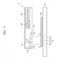
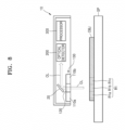
- FIGS. 7 and 8 are reference views illustrating a method of generating a hyperspectral image according to an embodiment.
- the optical irradiator 100 may irradiate the light ILa and ILb to the inspection region R1 which is a partial region of the object OBJ.
- the inspection region R1 of FIGS. 7 and 8 may be referred to as a first inspection region, and the inspection region R2 of FIGS. 11 and 12 may be referred to as a second inspection region R2.
- the inspection region R1 of FIGS. 7 and 8 may be referred to as a previous inspection region R1
- the inspection region R2 of FIGS. 11 and 12 may be referred to as a current inspection region R2.
- the inspection region R1 may include a plurality of sub-inspection regions R1a, R1b, and R1c (hereinafter, when there is no need to distinguish R1a, R1b, and R1c, R1a, R1b, and R1c are collectively referred to as R1a).
- the optical irradiator 100 may include a plurality of light sources, and a plurality of inspection lights ILa and ILb may be simultaneously irradiated to the inspection region R1. Therefore, lights may simultaneously reach the plurality of sub-inspection regions R1a.
- the optical detector 200 may receive the detection light OL generated by the object OBJ in response to the irradiated light.
- the detection light OL may indicate reflected light, scattering light, fluorescence, Raman spectrum, and so on.
- the detection light OL of the disclosure is not limited thereto and may indicate some or all of the light detected by the optical detector 200 as a result of irradiation of the light.
- the detection light OL may be provided again to the hyperspectral image sensor 10 by passing through the transmissive window 120.
- the optical path adjustment element 20 may adjust a path of the detection light OL and provide the detection light OL to the optical detector 200.
- the optical detector 200 may include a spectrum filter 230 and a spectrum signal generator 250 as shown, e.g., in FIGS. 5 and 6 .
- the spectrum filter 230 may receive detection light OL.
- the optical detector 200 may output sub-spectrum signals for each wavelength for a plurality of sub-inspection regions R1a.
- the spectrum filter 230 may output at least three sub-spectrum signals (e.g., sub-spectrum filter signals) of different wavelengths.
- the spectrum filter 230 may output red, green, and blue sub-spectrum signals.
- a plurality of sub-spectrum signals may correspond to a single sub-inspection region R1a, and each of the plurality of sub-spectrum signals that corresponds to a single sub-inspection region R1a may have a wavelength different from each other of the plurality of sub-spectrum signals that correspond to a single sub-inspection region R1a.
- the spectrum filter 230 may transmit the sub-spectrum signals to the spectrum signal generator 250 through a plurality of channels. For example, when the spectrum filter 230 splits red, green, and blue wavelengths, the spectrum filter 230 may transmit the sub-spectrum signals to the spectrum signal generator 250 through three channels.
- the spectrum signal generator 250 may generate sub-spectrum signals for each of a plurality of sub-inspection regions R1a based on the sub-spectrum signals.
- the spectrum signal generator 250 may include sets of a plurality of pixels.
- the sets of the plurality of pixels may correspond to the plurality of different sub-inspection regions R1a in the inspection region R1.
- the sets of the plurality of pixels may each include sets of a plurality of sub-pixels respectively corresponding to a plurality of wavelength bands. For example, a first set of sub-pixels may measure light of a first wavelength band, a second set of sub-pixels may measure light of a second wavelength band different from the first wavelength band, and a third set of sub-pixels may measure light of a third wavelength band different from the first wavelength band and the second wavelength band. Accordingly, the spectrum signal generator 250 may generate sub-spectrum signals for each of the sub-inspection regions R1a.
- the spectrum signal generator 250 may provide the sub-spectrum signals to the processor 300.
- the processor 300 may generate sub-hyperspectral images for each of the plurality of sub-inspection regions R1a based on the sub-spectrum signals.
- the sub-hyperspectral image may include spectrum distribution information of the detection light OL.
- the processor 300 may merge sub-hyperspectral images to generate a hyperspectral image of the inspection region R1.
- FIG. 9 is a reference view for describing FIGS. 7 and 8 .
- the inspection region R1 may include a first sub-inspection region R1a, a second sub-inspection region R1b, and a third sub-inspection region R1C.
- the optical detector 200 includes a lens 220, a spectrum filter 230, and a spectrum signal generator 250.
- the optical detector 200 may simultaneously receive the detection light OL generated in the inspection region R1 of the object OBJ.
- the optical detector 200 splits the detection light OL based on the number of preset wavelength bands.
- FIG. 9 illustrates that the detection light (OL) is split into three wavelength bands, but the number of wavelength bands may be increased or reduced according to an embodiment.
- the optical detector 200 may split the detection light generated in each of the plurality of sub-inspection regions R1a, R1b, and R1c into three wavelength bands.
- the optical detector 200 may split the detection light generated in the first sub-inspection region R1a into three wavelength bands and output a first sub-spectrum signal.
- the optical detector 200 may split the detection light generated in the second sub-inspection region R1b into three wavelength bands and output a second sub-spectrum signal.
- the optical detector 200 may split the detection light generated in the third sub-inspection region R1C into three wavelength bands and output a third sub-spectrum signal.
- the optical detector 200 generates sub-spectrum signals for the plurality of sub-inspection regions R1a, R1b, and R1c based on the sub-spectrum signals.
- the optical detector 200 may generate a first sub-spectrum signal based on the first sub-spectrum signal.
- the optical detector 200 may generate a second sub-spectrum signal based on the second sub-spectrum signal.
- the optical detector 200 may generate a third sub-spectrum signal based on the third sub-spectrum signal.
- the optical detector 200 may provide the first to third sub-spectrum signals to the processor 300.
- the hyperspectral image sensor 10 of the disclosure merges the hyperspectral images
- the number of channels through which light of the same wavelength passes is large, and thus, the same position of the object OBJ is measured n times to increase a signal S n times.
- noise N is summed according to a root mean square equation and is proportional to (n) 1/2 . Therefore, a signal noise ratio (SNR) is increased to (n) 1/2 in the same merge time and the same scan step condition.
- the optical irradiator 100 irradiates light to the inspection region R1 which is a partial region of the object OBJ.
- the processor 300 In operation S1040, the processor 300 generates a hyperspectral image of the inspection region R1 based on the spectrum signals.
- the processor 300 generates sub-hyperspectral images for each of the plurality of sub-inspection regions R1a based on the sub-spectrum signals.
- the processor 300 may merge sub-hyperspectral images to generate a hyperspectral image of the inspection region R1.
- the hyperspectral image sensor 10 of the disclosure generates a hyperspectral image of an area of the object OBJ, and thus, high-speed scan may be performed compared to a line scan method or a point scan method.
- a pixel area of the spectrum signal generator 250 increases, and merging time of the hyperspectral image is reduced, and thus, the object OBJ may be scanned at high speed while maintaining a scan step and resolution.
- a scan step and resolution is reduced, and thus, the object OBJ may be scanned at high speed.
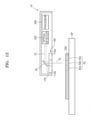
- FIGS. 11 and 12 are reference views illustrating a method of generating a hyperspectral image according to an embodiment.
- the optical irradiator 100 may be moved to a position facing the second inspection region R2 from a position facing the first inspection region R1.
- the first inspection region R1 may be referred to as a previous inspection region, and the second inspection region R2 may be referred to as a current inspection region.
- the second inspection region R2 may be different from the first inspection region R1. According to an embodiment, at least a part of the second inspection region R2 may overlap the first inspection region R1.
- FIGS. 11 and 12 illustrate that the hyperspectral image sensor 10 is totally moved, and the hyperspectral image sensor 10 may further include an adjustment mechanism for adjusting at least one of a position and an angle of the optical irradiator 100, and the optical irradiator 100 may be moved according to the control of the adjustment mechanism.
- the second inspection region R2 (e.g., the second partial region of the object OBJ) may include a plurality of sub-inspection regions R2a, R2b, and R2c (hereinafter, when there is no need to distinguish R2a, R2b, and R2c, R2a, R2b, and R2c are collectively referred to as R2a).
- the processor 300 may generate sub-hyperspectral images for each of the plurality of sub-inspection regions R2a based on the sub-spectrum signals.
- the processor 300 may merge the sub-hyperspectral images to generate a hyperspectral image of the second inspection region R2.
- the hyperspectral image generated in the first inspection region R1 may be referred to as a first hyperspectral image
- a hyperspectral image generated in the second inspection region R2 may be referred to as a second hyperspectral image.
- the processor 300 may merge the first hyperspectral image and the second hyperspectral image to generate a full hyperspectral image of the object OBJ.
- FIG. 13 is a flowchart illustrating a method of generating the full hyperspectral image according to an embodiment.
- the object OBJ may be scanned at high speed, and the hyperspectral image may be merged at high speed.
- FIG. 14 is a flowchart illustrating a method of generating a full hyperspectral image according to an embodiment.
- the optical irradiator 100 may irradiate light to the current inspection region R2 having at least a part overlapping the previous inspection region R1.
- the processor 300 may generate a full hyperspectral image of the object OBJ by removing an overlapping hyperspectral image of the overlapping region from a previous hyperspectral image generated in the previous inspection region R1 and a current hyperspectral image generated in the current inspection region R2.
- the processor 300 may remove a hyperspectral image of the overlapping region from either the previous hyperspectral image or the current hyperspectral image. Accordingly, it is possible to prevent a hyperspectral image of an overlapping region from being reflected in the full hyperspectral image.
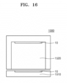
- FIGS. 15 and 16 are reference views illustrating a hyperspectral image sensor in a clothing management apparatus.
- the hyperspectral image sensor 10 may be on a clothing management apparatus 1500.
- the clothing management apparatus 1500 may be implemented by an electronic device for removing odor, dust, or wrinkles of the clothing contained in the interior by using a method of spraying air or steam.
- the clothing management apparatus 1500 may have a clothing management chamber 1520 therein.
- An opening is formed on a front surface of a main body, and a door 1510 is rotatably coupled to the main body to be opened and closed.
- the door 1510 may be installed to open and close the clothing management chamber 1520.
- the door 1510 may be coupled to the main body by a connection member such as a hinge.
- the clothing management chamber 1520 may form a space in which clothing is accommodated.
- the clothing management chamber 1520 may include a supporting member to support the clothing accommodated therein.
- the hyperspectral image sensor 10 may be on at least one of an inner surface of the door 1510 and an inner surface of the clothing management chamber 1520.
- the hyperspectral image sensor 10 may be adjacent to the clothing when the door 1510 is closed.
- the hyperspectral image sensor 10 may be adjacent to clothing when the clothing is accommodated in the clothing management chamber 1520 regardless of opening and closing of the door 1510.
- the hyperspectral image sensor 10 of the disclosure may accurately sense the clothing in a position where field of view (FOV) is not fully secured.
- the hyperspectral image sensor 10 may scan the clothing.
- the clothing management apparatus 1500 may analyze a material of the clothing under a preset condition.
- the preset condition may include a scanning length.
- the clothing management apparatus 1500 may select an operation mode according to a clothing material. Strength of steam, a degree of heat, a degree of dehumidification, an output of a clothing support, and so on may be changed depending on the operation mode.
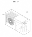
- FIGS. 17 and 18 are reference views illustrating a hyperspectral image sensor in an outdoor unit.
- the hyperspectral image sensor 10 may be on an outdoor unit 1700.
- An outdoor unit 1700 may include a heat exchanger 1710 for exchanging heat with external air.
- the outdoor unit 1700 is placed in an outdoor, and thus, a pollution source may be easily attached to the heat exchanger 1710 due to moisture.
- the pollution source may indicate fungi but is not limited thereto.
- the hyperspectral image sensor 10 may be adjacent to the heat exchanger 1710 to sense the pollution source.
- the hyperspectral image sensor 10 of the disclosure may accurately sense the pollution source in a position where field of view (FOV) is not fully secured.
- FOV field of view
- the outdoor unit 1700 may scan the pollution source attached to the heat exchanger 1710.
- the outdoor unit 1700 may scan the pollution source attached to the heat exchanger 1710 under a preset condition.
- the preset condition may include a scanning length.
- the outdoor unit 1700 may display presence of the pollution source on a display of an indoor unit.
- the outdoor unit 1700 may determine cleaning time of the outdoor unit 1700 according to the amount of pollution source and may remove the pollution source based on the cleaning time. For example, the outdoor unit 1700 may remove a pollution source by driving a blowing fan.
- the embodiments described above may be implemented by a program that may be executed by a computer and may be implemented by a general-purpose digital computer that executes the program by using a computer-readable recording medium.
- the data used in the embodiments described above may be recorded on a computer-readable recording medium through various devices.
- the computer-readable recording medium may include a storage medium such as a magnetic storage medium (for example, a read only memory (ROM), a floppy disk, a hard disk, or so on) or an optical reading medium (for example, a compact disk (CD)-ROM, a digital video disk (DVD), or so on).
Landscapes
- Physics & Mathematics (AREA)
- Spectroscopy & Molecular Physics (AREA)
- General Physics & Mathematics (AREA)
- Health & Medical Sciences (AREA)
- Life Sciences & Earth Sciences (AREA)
- Chemical & Material Sciences (AREA)
- Analytical Chemistry (AREA)
- Biochemistry (AREA)
- General Health & Medical Sciences (AREA)
- Immunology (AREA)
- Pathology (AREA)
- Engineering & Computer Science (AREA)
- Computer Vision & Pattern Recognition (AREA)
- Theoretical Computer Science (AREA)
- Investigating Or Analysing Materials By Optical Means (AREA)
- Spectrometry And Color Measurement (AREA)
Description
- The disclosure relates to a hyperspectral image sensor and an operating method thereof.
- Hyperspectral imaging technology is used to simultaneously measure the optical spectra of each pixel of an image of an object. Hyperspectral imaging technology may be used to measure an optical spectrum of each part of an object in a short time compared to an existing spot spectrum.
- The respective pixels of an image include spectral information, and thus, hyperspectral imaging technology may be applied in various ways to measure the properties and characteristics of an object by capturing an image thereof. For example, hyperspectral imaging technology may be applied to agricultural condition analysis, mineral distribution, surface vegetation, pollution level, and so on by imaging the ground by using a drone, a satellite, an aircraft, and so on. Hyperspectral imaging technology has also been considered for other applications in various fields such as food safety, skin/face analysis, and biological tissue analysis.
- Hyperspectral imaging technology is used to obtain hyperspectral images by using a point scan method or a line scan method. When the point scan method or the line scan method is used, signals are obtained only in a small region of an object, and thus, a scan speed is inevitably reduced to achieve an expected signal-to-noise ratio (SNR). Prior art is disclosed in
US2018/242901 A1 ,US2008/144001 A1, and Wang Meng: "Fluorescence Image Based Food Quality Measurement"ln: "Fluorescence Image Based Food Quality Measurement", 1 February 2014 , Master Thesis, The University of Tokyo. - The disclosure provides a hyperspectral image sensor and an operating method thereof. Technical problems of the disclosure are not limited to the technical problems described above, and other technical problems may be inferred from the following embodiments.
- Additional aspects will be set forth in part in the description which follows and, in part, will be apparent from the description, or may be learned by practice of embodiments of the disclosure.
- In accordance with an aspect of the disclosure, a hyperspectral image sensor includes an optical irradiator configured to irradiate light to a partial region of an object; an optical detector configured to receive detection light generated in the partial region in response to the irradiated light and generate a plurality of spectrum signals, each of the plurality of spectrum signals corresponding to a respective sub-region of a plurality of sub-regions included in the partial region; and a processor configured to generate a hyperspectral image of the partial region based on the plurality of spectrum signals.
- The optical detector includes a lens configured to receive the detection light generated in the partial region; a spectrum filter configured to receive the detection light and output a plurality of sub-spectrum filter signals for each sub-region of the plurality of sub-regions, each sub-spectrum filter signal of the plurality of sub-spectrum filter signals corresponding to a different wavelength for the sub-region; and a spectrum signal generator configured to generate a plurality of sub-spectrum signals for each of the plurality of sub-regions based on the plurality of sub-spectrum filter signals.
- The processor is configured to generate a plurality of sub-hyperspectral images based on the plurality of sub-spectrum signals, each of the plurality of sub-hyperspectral images corresponding to a respective sub-region of the plurality of sub-regions, and the processor may be further configured to merge the plurality of sub-hyperspectral images with each other to generate the hyperspectral image of the partial region.
- For each of the plurality of sub-regions, the spectrum filter may output at least three sub-spectrum filter signals, each of the at least three sub-spectrum filter signals corresponding to a different wavelength.
- The spectrum filter may be further configured to transmit the plurality of sub-spectrum signals to the spectrum signal generator through a plurality of channels.
- The optical irradiator may be arranged at a preset distance from the object.
- The optical irradiator may include a light source array including a plurality of light sources, and the light source array may be configured to emit a plurality of inspection lights toward the partial region.
- The light source array may be further configured to simultaneously emit the plurality of inspection lights toward the partial region.
- The optical irradiator may include a transmissive window configured to receive the detection light generated in the partial region.
- The transmissive window may be formed in an opening of the optical irradiator.
- The optical irradiator may be further configured to emit light toward a second partial region of the object, different from the partial region, after emitting the light to the partial region.
- The processor may be further configured to generate a full hyperspectral image of the object based on the hyperspectral image generated in the partial region and a second hyperspectral image generated in the second partial region.
- The optical irradiator may be further configured to emit light toward a second partial region of the object, the second partial region at least partially overlapping the partial region.
- The processor may be further configured to generate a full hyperspectral image of the object by removing an overlapping hyperspectral image of an overlapping region in which the second partial region at least partially overlaps the partial region.
- In accordance with an aspect of the disclosure, an operating method of a hyperspectral image sensor includes irradiating light to a partial region of an object; receiving detection light generated in the partial region in response to the irradiated light; generating a plurality of spectrum signals, each of the plurality of spectrum signals corresponding to a respective sub-region of a plurality of sub-regions included in the partial region; and generating a hyperspectral image of the partial region based on the plurality of spectrum signals.
- In the irradiating of the light, a plurality of inspection lights may be simultaneously irradiated to the partial region.
- The generating of the plurality of spectrum signals includes outputting a plurality of sub-spectrum filter signals for each sub-region of the plurality of sub-regions, each sub-spectrum filter signal of the plurality of sub-spectrum filter signals corresponding to a different wavelength for the sub-region; and generating a plurality of sub-spectrum signals for each of the plurality of sub-regions based on the plurality of sub-spectrum filter signals.
- The generating of the hyperspectral image includes generating a plurality of sub-hyperspectral images based on the plurality of sub-spectrum signals, each of the plurality of sub-hyperspectral images corresponding to a respective sub-region of the plurality of sub-regions; and merging the plurality of sub-hyperspectral images with each other to generate the hyperspectral image of the partial region.
- The operating may further include irradiating light to a second partial region of the object different from the partial region; and generating a full hyperspectral image of the object based on the hyperspectral image generated in the partial region and a second hyperspectral image generated in the second partial region.
- The operating method may further include irradiating light to a second partial region of the object, the second partial region at least partially overlapping the partial region; and generating a full hyperspectral image of the object by removing an overlapping hyperspectral image of an overlapping region in which the second partial region at least partially overlaps the partial region.
- The above and other aspects, features, and advantages of certain embodiments of the disclosure will be more apparent from the following description taken in conjunction with the accompanying drawings, in which:
-
FIG. 1 is a block diagram of a hyperspectral image sensor according to an embodiment; -
FIG. 2 is a conceptual view of a hyperspectral image sensor according to an embodiment; -
FIG. 3 is a conceptual view of an optical irradiator according to an embodiment; -
FIG. 4 is a conceptual view of an optical irradiator according to an embodiment; -
FIG. 5 is a conceptual view of an optical detector according to an embodiment; -
FIG. 6 is a conceptual view of an optical detector according to an embodiment; -
FIGS. 7 and8 are reference views illustrating a method of generating a hyperspectral image according to an embodiment; -
FIG. 9 is a reference view forFIGS. 7 to 8 ; -
FIG. 10 is a flowchart illustrating a method of generating a hyperspectral image according to an embodiment; -
FIGS. 11 and12 are reference views illustrating a method of generating a hyperspectral image according to an embodiment; -
FIG. 13 is a flowchart illustrating a method of generating a hyperspectral image according to an embodiment; -
FIG. 14 is a flowchart illustrating a method of generating a full hyperspectral image according to an embodiment; -
FIGS. 15 to 16 are reference views illustrating a hyperspectral image sensor in a clothing management apparatus; and -
FIGS. 17 and18 are reference views illustrating a hyperspectral image sensor in an outdoor unit. - Reference will now be made in detail to embodiments, examples of which are illustrated in the accompanying drawings, wherein like reference numerals refer to like elements throughout. In this regard, embodiments may have different forms and should not be construed as being limited to the descriptions set forth herein. Accordingly, embodiments are merely described below, by referring to the figures, to explain aspects. As used herein, the term "and/or" includes any and all combinations of one or more of the associated listed items. Expressions such as "at least one of," when preceding a list of elements, modify the entire list of elements and do not modify the individual elements of the list.
- Some embodiments of the disclosure may be represented by functional block configurations and various processing operations. Some or all of the functional block configurations may be implemented by various pieces of hardware and/or software for performing certain functions. For example, functional blocks of the present disclosure may be implemented by one or more microprocessors or may be implemented by circuit configurations for a certain function. In addition, for example, the functional blocks of the present disclosure may be implemented in various programming or scripting languages. The functional blocks may be implemented by using an algorithm executed by one or more processors. In addition, the present disclosure may adopt the related art for an electronic configuration, signal processing, data processing and/or so on. The terms "mechanism", "element", "means", "configuration", and so on may be widely used and are not limited to mechanical and physical configurations.
- In addition, connection lines or connection members between components illustrated in the drawing are examples in which functional connections and/or physical or circuit connections are illustrated. In an actual device, connections between components may be represented by a variety of functional connections, physical connections, or circuit connections that may be replaced or added.
-
FIG. 1 is a block diagram of a hyperspectral image sensor according to an embodiment. - Referring to
FIG. 1 , ahyperspectral image sensor 10 may include anoptical irradiator 100, anoptical detector 200, and aprocessor 300. - The
optical irradiator 100 may irradiate an object OBJ illustrated inFIG. 2 with light. Theoptical irradiator 100 may irradiate light to an inspection region that is a partial region of the object OBJ. Theoptical irradiator 100 may irradiate light while changing an inspection region of the object OBJ. - The
optical irradiator 100 may be adjacent to the object OBJ. Theoptical irradiator 100 may be arranged at a preset distance from the object (OBJ). For example, a distance between thelight irradiator 100 and the object OBJ may be set to be 10 cm or less but is not limited thereto. As described below, theprocessor 300 generates a hyperspectral image of the object OBJ by using an area scan method, not a line scan method or a point scan method, and thus, theoptical irradiator 100 may be adjacent to the object OBJ. - A wavelength of the light emitted by the
light irradiator 100 may be set to be different depending on the type of the object OBJ. For example, when the object OBJ is meat, thelight irradiator 100 may emit light with a wavelength of about 335 nm to about 370 nm. For this purpose, theoptical irradiator 100 may include a light emitting diode (LED). - The
optical detector 200 may receive detection light emitted from the object OBJ. In an embodiment, the detection light may indicate the light which is emitted by theoptical irradiator 100, reflected by the object OBJ, and then received by theoptical detector 200. In an embodiment, the detection light may indicate the light which is emitted by theoptical irradiator 100, scattered by the object OBJ, and then received by theoptical detector 200. In an embodiment, the detection light may also indicate fluorescence emitted from the object OBJ when light emitted by theoptical irradiator 100 is absorbed into the object OBJ. In an embodiment, the detection light may also indicate Raman spectrum. However, the detection light of the disclosure is not limited thereto and may indicate all of the light detected by theoptical detector 200 as a result of light irradiation. - The
optical detector 200 may generate a spectrum signal based on the detection light. Theoptical detector 200 may generate a spectrum signal by splitting the detection light. - The
optical detector 200 may receive detection light generated in the inspection region and generate spectrum signals for a plurality of sub-inspection regions (e.g., sub-regions) included in the inspection region. - The
processor 300 may receive a spectrum signal from theoptical detector 200. Theprocessor 300 may generate a hyperspectral image of the object OBJ based on the spectrum signal. The hyperspectral image may indicate a combination of spectrum distribution for each position of the object OBJ. -
FIG. 2 is a conceptual view of a hyperspectral image sensor according to an embodiment,FIG. 3 is a conceptual view of an optical irradiator according to an embodiment,FIG. 4 is a conceptual view of an optical irradiator according to an embodiment,FIG. 5 is a conceptual view of an optical detector according to an embodiment, andFIG. 6 is a conceptual view of an optical detector according to an embodiment. - Referring to
FIG. 2 , the object OBJ may be on a support SP. The object OBJ may indicate anything which may require a hyperspectral image such as clothing, a heat exchanger, and meat. - The
optical irradiator 100 may face the object OBJ. Theoptical irradiator 100 may irradiate the object OBJ with light. In this case, light emitted from theoptical irradiator 100 may be referred to as inspection light ILa and ILb (when there is no need to distinguish ILa and ILb below, ILa and ILb are referred to as IL). - Referring to
FIGS. 3 and 4 , theoptical irradiator 100 may includelight source arrays - The light source array 110 may include a first
light source array 110a, a secondlight source array 110b, and atransmissive window 120. The firstlight source array 110a and the secondlight source array 110b may be separated from each other with thetransmissive window 120 therebetween. The firstlight source array 110a and the secondlight source array 110b may each include a plurality of light sources arranged in one direction. For example, the light sources may include LEDs. - The plurality of light sources may be arranged along the
transmissive window 120.FIG. 3 illustrates that the the firstlight source array 110a and the secondlight source array 110b each include two lines of but are not limited thereto. - The
transmissive window 120 may receive detection light OL generated by the object OBJ by irradiation of light. - The
transmissive window 120 may be formed of a transparent material as illustrated inFIG. 3 . For example, thetransmissive window 120 may be formed of transparent plastic or glass. Thetransmissive window 120 may be formed of a material with high durability to a low temperature. The detection light OL may be provided to theoptical detector 200 through thetransmissive window 120. - According to an embodiment, the
transmissive window 120 may be formed as an opening as illustrated inFIG. 4 . The detection light OL may be provided to theoptical detector 200 through the opening. - Referring to
FIG. 2 , the detection light OL may be provided to theoptical detector 200 by an opticalpath adjustment element 20. According to an embodiment, theoptical detector 200 may include a hyperspectral camera. - Referring to
FIGS. 5 to 6 , theoptical detector 200 may include alens 220, aspectrum filter 230, and aspectrum signal generator 250. According to an embodiment, theoptical detector 200 may further include aslit element 210 and a condensinglens 240. - The
slit element 210 may be used to extract parts required for testing from the detection light OL. The detection light OL may be radiated from theslit element 210. - The
lens 220 may receive the detection light OL passing through theslit element 210. Thelens 220 may adjust the detection light OL to be parallel or convergent. For example, thelens 220 may include a collimating lens. The collimating lens may include a convex lens. - The
spectrum filter 230 may split the detection light OL provided from thelens 220. Thespectrum filter 230 may be mechanically formed as illustrated inFIG. 5 or may be electrically formed as illustrated inFIG. 6 . For example, referring toFIG. 5 , thespectrum filter 230 may include a prism. - Light of different wavelength bands may pass through the
spectrum filter 230. Thespectrum filter 230 may filter the detection light OL provided from thelens 220 to have spatially different wavelengths. In other words, the detection light OL passing through different regions of thespectrum filter 230 may have different wavelengths. The detection light OL split by thespectrum filter 230 may be provided to thespectrum signal generator 250 through the condensinglens 240. For example, the condensinglens 240 may include a convex lens. - The
spectrum signal generator 250 may generate a spectrum signal from detection light OL. Thespectrum signal generator 250 may provide the spectrum signal to theprocessor 300. - The
processor 300 may generate a hyperspectral image of the object OBJ based on the spectrum signal. A hyperspectral image of the object OBJ may be generated by merging spectral distribution information for each position of the object OBJ. In other words, the hyperspectral image of the object OBJ may be a set of spectral distributions for each position of the object OBJ. For example, theprocessor 300 may generate a hyperspectral image of the object OBJ by removing offsets from a plurality of sub-hyperspectral images and summing the sub-hyperspectral images from which the offsets are removed. However, a method of generating a hyperspectral image of the disclosure is not limited thereto, and a method of generating a known hyperspectral image may be used therefor. -
FIGS. 7 and8 are reference views illustrating a method of generating a hyperspectral image according to an embodiment. - Referring to
FIGS. 7 and8 , theoptical irradiator 100 may irradiate the light ILa and ILb to the inspection region R1 which is a partial region of the object OBJ. In order to distinguish the inspection region R1 ofFIGS. 7 and8 from an inspection region R2 ofFIGS. 11 and12 , the inspection region R1 ofFIGS. 7 and8 may be referred to as a first inspection region, and the inspection region R2 ofFIGS. 11 and12 may be referred to as a second inspection region R2. Alternatively, the inspection region R1 ofFIGS. 7 and8 may be referred to as a previous inspection region R1, and the inspection region R2 ofFIGS. 11 and12 may be referred to as a current inspection region R2. - The inspection region R1 may include a plurality of sub-inspection regions R1a, R1b, and R1c (hereinafter, when there is no need to distinguish R1a, R1b, and R1c, R1a, R1b, and R1c are collectively referred to as R1a).
- Referring to
FIG. 7 , theoptical irradiator 100 may include a plurality of light sources, and a plurality of inspection lights ILa and ILb may be simultaneously irradiated to the inspection region R1. Therefore, lights may simultaneously reach the plurality of sub-inspection regions R1a. - Referring to
FIG. 8 , theoptical detector 200 may receive the detection light OL generated by the object OBJ in response to the irradiated light. For example, the detection light OL may indicate reflected light, scattering light, fluorescence, Raman spectrum, and so on. However, the detection light OL of the disclosure is not limited thereto and may indicate some or all of the light detected by theoptical detector 200 as a result of irradiation of the light. - The detection light OL may be provided again to the
hyperspectral image sensor 10 by passing through thetransmissive window 120. The opticalpath adjustment element 20 may adjust a path of the detection light OL and provide the detection light OL to theoptical detector 200. - The
optical detector 200 may include aspectrum filter 230 and aspectrum signal generator 250 as shown, e.g., inFIGS. 5 and 6 . Thespectrum filter 230 may receive detection light OL. Theoptical detector 200 may output sub-spectrum signals for each wavelength for a plurality of sub-inspection regions R1a. Thespectrum filter 230 may output at least three sub-spectrum signals (e.g., sub-spectrum filter signals) of different wavelengths. For example, thespectrum filter 230 may output red, green, and blue sub-spectrum signals. In other words, a plurality of sub-spectrum signals may correspond to a single sub-inspection region R1a, and each of the plurality of sub-spectrum signals that corresponds to a single sub-inspection region R1a may have a wavelength different from each other of the plurality of sub-spectrum signals that correspond to a single sub-inspection region R1a. - The
spectrum filter 230 may transmit the sub-spectrum signals to thespectrum signal generator 250 through a plurality of channels. For example, when thespectrum filter 230 splits red, green, and blue wavelengths, thespectrum filter 230 may transmit the sub-spectrum signals to thespectrum signal generator 250 through three channels. - The
spectrum signal generator 250 may generate sub-spectrum signals for each of a plurality of sub-inspection regions R1a based on the sub-spectrum signals. - The
spectrum signal generator 250 may include sets of a plurality of pixels. In an embodiment, the sets of the plurality of pixels may correspond to the plurality of different sub-inspection regions R1a in the inspection region R1. The sets of the plurality of pixels may each include sets of a plurality of sub-pixels respectively corresponding to a plurality of wavelength bands. For example, a first set of sub-pixels may measure light of a first wavelength band, a second set of sub-pixels may measure light of a second wavelength band different from the first wavelength band, and a third set of sub-pixels may measure light of a third wavelength band different from the first wavelength band and the second wavelength band. Accordingly, thespectrum signal generator 250 may generate sub-spectrum signals for each of the sub-inspection regions R1a. - The
spectrum signal generator 250 may provide the sub-spectrum signals to theprocessor 300. - The
processor 300 may generate sub-hyperspectral images for each of the plurality of sub-inspection regions R1a based on the sub-spectrum signals. The sub-hyperspectral image may include spectrum distribution information of the detection light OL. - The
processor 300 may merge sub-hyperspectral images to generate a hyperspectral image of the inspection region R1. -
FIG. 9 is a reference view for describingFIGS. 7 and8 . - Referring to
FIG. 9 , the inspection region R1 may include a first sub-inspection region R1a, a second sub-inspection region R1b, and a third sub-inspection region R1C. - The
optical detector 200 includes alens 220, aspectrum filter 230, and aspectrum signal generator 250. Theoptical detector 200 may simultaneously receive the detection light OL generated in the inspection region R1 of the object OBJ. - The
optical detector 200 splits the detection light OL based on the number of preset wavelength bands.FIG. 9 illustrates that the detection light (OL) is split into three wavelength bands, but the number of wavelength bands may be increased or reduced according to an embodiment. - The
optical detector 200 may split the detection light generated in each of the plurality of sub-inspection regions R1a, R1b, and R1c into three wavelength bands. Theoptical detector 200 may split the detection light generated in the first sub-inspection region R1a into three wavelength bands and output a first sub-spectrum signal. Theoptical detector 200 may split the detection light generated in the second sub-inspection region R1b into three wavelength bands and output a second sub-spectrum signal. Theoptical detector 200 may split the detection light generated in the third sub-inspection region R1C into three wavelength bands and output a third sub-spectrum signal. - The
optical detector 200 generates sub-spectrum signals for the plurality of sub-inspection regions R1a, R1b, and R1c based on the sub-spectrum signals. Theoptical detector 200 may generate a first sub-spectrum signal based on the first sub-spectrum signal. Theoptical detector 200 may generate a second sub-spectrum signal based on the second sub-spectrum signal. Theoptical detector 200 may generate a third sub-spectrum signal based on the third sub-spectrum signal. Theoptical detector 200 may provide the first to third sub-spectrum signals to theprocessor 300. - The
processor 300 generates sub-hyperspectral images for each of the plurality of sub-inspection regions based on the sub-spectrum signals. Theprocessor 300 may generate a first sub-hyperspectral image I1a for the first sub-inspection region R1a based on the first sub-spectrum signal. Theprocessor 300 may generate a second sub-hyperspectral image I1b for the second sub-inspection region R1b based on the second sub-spectrum signal. Theprocessor 300 may generate a third sub-hyperspectral image I1c for the third sub-inspection region R1c based on the third sub-spectrum signal. - The
processor 300 merges the first to third hyperspectral images I1a to I1c to generate a hyperspectral image on the inspection region R1. - When the
hyperspectral image sensor 10 of the disclosure merges the hyperspectral images, the number of channels through which light of the same wavelength passes is large, and thus, the same position of the object OBJ is measured n times to increase a signal S n times. In addition, there is no correlation between N hyperspectral images, and thus, noise N is summed according to a root mean square equation and is proportional to (n)1/2. Therefore, a signal noise ratio (SNR) is increased to (n)1/2 in the same merge time and the same scan step condition. -
FIG. 10 is a flowchart illustrating a method of generating a hyperspectral image according to an embodiment. - Referring to
FIG. 10 , in operation S1010, theoptical irradiator 100 irradiates light to the inspection region R1 which is a partial region of the object OBJ. - The
optical irradiator 100 may include a light source array including a plurality of light sources, and the light source array may simultaneously emit a plurality of inspection lights toward the inspection region R1. - In operation S1020, the
optical detector 200 receives the detection light OL generated in the inspection region R1 by the irradiation of light. - The
optical detector 200 may simultaneously receive the detection light OL generated in the inspection region R1 of the object OBJ. - In operation S1030, the
optical detector 200 generates spectrum signals for each of a plurality of sub-inspection regions R1a included in the inspection region R1. - The
optical detector 200 outputs sub-spectrum signals for each wavelength for a plurality of sub-inspection regions R1a. For example, three wavelength bands may be set, and theoptical detector 200 may output sub-spectrum signals corresponding to red, green, and blue wavelength bands for each of the sub-inspection regions R1a. Theoptical detector 200 may generate sub-spectrum signals for each of the plurality of sub-inspection regions R1a based on the sub-spectrum signals. - In operation S1040, the
processor 300 generates a hyperspectral image of the inspection region R1 based on the spectrum signals. - The
processor 300 generates sub-hyperspectral images for each of the plurality of sub-inspection regions R1a based on the sub-spectrum signals. Theprocessor 300 may merge sub-hyperspectral images to generate a hyperspectral image of the inspection region R1. - The
hyperspectral image sensor 10 of the disclosure generates a hyperspectral image of an area of the object OBJ, and thus, high-speed scan may be performed compared to a line scan method or a point scan method. In addition, according to thehyperspectral image sensor 10 of the disclosure, a pixel area of thespectrum signal generator 250 increases, and merging time of the hyperspectral image is reduced, and thus, the object OBJ may be scanned at high speed while maintaining a scan step and resolution. In addition, according to thehyperspectral image sensor 10 of the disclosure, a scan step and resolution is reduced, and thus, the object OBJ may be scanned at high speed. -
FIGS. 11 and12 are reference views illustrating a method of generating a hyperspectral image according to an embodiment. - Referring to
FIGS. 11 and12 , theoptical irradiator 100 may be moved to a position facing the second inspection region R2 from a position facing the first inspection region R1. The first inspection region R1 may be referred to as a previous inspection region, and the second inspection region R2 may be referred to as a current inspection region. The second inspection region R2 may be different from the first inspection region R1. According to an embodiment, at least a part of the second inspection region R2 may overlap the first inspection region R1. - In addition,
FIGS. 11 and12 illustrate that thehyperspectral image sensor 10 is totally moved, and thehyperspectral image sensor 10 may further include an adjustment mechanism for adjusting at least one of a position and an angle of theoptical irradiator 100, and theoptical irradiator 100 may be moved according to the control of the adjustment mechanism. - The second inspection region R2 (e.g., the second partial region of the object OBJ) may include a plurality of sub-inspection regions R2a, R2b, and R2c (hereinafter, when there is no need to distinguish R2a, R2b, and R2c, R2a, R2b, and R2c are collectively referred to as R2a).
- Referring to
FIG. 11 , theoptical irradiator 100 may irradiate the inspection light ILa and ILb to the subject OBJ at a position facing the second inspection region R2. Theoptical irradiator 100 may include a plurality of light sources and simultaneously irradiate a plurality of inspection lights ILa and ILb to the second inspection region R2. Therefore, lights may simultaneously reach the plurality of sub-inspection regions R2a. - Referring to
FIG. 8 , theoptical detector 200 may receive the detection light OL generated by the object OBJ in response to the irradiated light. Theoptical detector 200 may output sub-spectrum signals for each wavelength for each of the plurality of sub-inspection regions R1a based on the detection light OL. Theoptical detector 200 may generate sub-spectrum signals for each of the plurality of sub-inspection regions R2a based on the sub-spectrum signals. A method of generating a sub-spectrum signal inFIG. 12 may be substantially the same as the method of generating the sub-spectral signal inFIGS. 7 and8 . - The
processor 300 may generate sub-hyperspectral images for each of the plurality of sub-inspection regions R2a based on the sub-spectrum signals. Theprocessor 300 may merge the sub-hyperspectral images to generate a hyperspectral image of the second inspection region R2. The hyperspectral image generated in the first inspection region R1 may be referred to as a first hyperspectral image, and a hyperspectral image generated in the second inspection region R2 may be referred to as a second hyperspectral image. - The
processor 300 may merge the first hyperspectral image and the second hyperspectral image to generate a full hyperspectral image of the object OBJ. -
FIG. 13 is a flowchart illustrating a method of generating the full hyperspectral image according to an embodiment. - Referring to
FIG. 13 , in operation S1310, theoptical irradiator 100 may irradiate light to the current inspection region R2 different from the previous inspection region R1. The previous inspection region R1 may not overlap the current inspection region R2. - In operation S1320, the
optical irradiator 100 may generate a full hyperspectral image of the object OBJ based on the previous hyperspectral image generated in the previous inspection region R1 and the current hyperspectral image generated in the current inspection region R2. - When the previous inspection region R1 does not overlap the current inspection region R2, the object OBJ may be scanned at high speed, and the hyperspectral image may be merged at high speed.
-
FIG. 14 is a flowchart illustrating a method of generating a full hyperspectral image according to an embodiment. - Referring to
FIG. 14 , in operation S1410, theoptical irradiator 100 may irradiate light to the current inspection region R2 having at least a part overlapping the previous inspection region R1. - In operation S1420, the
processor 300 may generate a full hyperspectral image of the object OBJ by removing an overlapping hyperspectral image of the overlapping region from a previous hyperspectral image generated in the previous inspection region R1 and a current hyperspectral image generated in the current inspection region R2. - In an embodiment, when merging the previous hyperspectral image with the current hyperspectral image, the
processor 300 may remove a hyperspectral image of the overlapping region from either the previous hyperspectral image or the current hyperspectral image. Accordingly, it is possible to prevent a hyperspectral image of an overlapping region from being reflected in the full hyperspectral image. -
FIGS. 15 and16 are reference views illustrating a hyperspectral image sensor in a clothing management apparatus. - Referring to
FIGS. 15 and16 , thehyperspectral image sensor 10 may be on aclothing management apparatus 1500. - The
clothing management apparatus 1500 may be implemented by an electronic device for removing odor, dust, or wrinkles of the clothing contained in the interior by using a method of spraying air or steam. - The
clothing management apparatus 1500 may have aclothing management chamber 1520 therein. An opening is formed on a front surface of a main body, and adoor 1510 is rotatably coupled to the main body to be opened and closed. Thedoor 1510 may be installed to open and close theclothing management chamber 1520. Thedoor 1510 may be coupled to the main body by a connection member such as a hinge. - The
clothing management chamber 1520 may form a space in which clothing is accommodated. Theclothing management chamber 1520 may include a supporting member to support the clothing accommodated therein. - The
hyperspectral image sensor 10 may be on at least one of an inner surface of thedoor 1510 and an inner surface of theclothing management chamber 1520. Thehyperspectral image sensor 10 may be adjacent to the clothing when thedoor 1510 is closed. Thehyperspectral image sensor 10 may be adjacent to clothing when the clothing is accommodated in theclothing management chamber 1520 regardless of opening and closing of thedoor 1510. - The
hyperspectral image sensor 10 of the disclosure may accurately sense the clothing in a position where field of view (FOV) is not fully secured. - When the
door 1510 is closed and a user input is received, thehyperspectral image sensor 10 may scan the clothing. - The
clothing management apparatus 1500 may analyze a material of the clothing under a preset condition. For example, the preset condition may include a scanning length. Theclothing management apparatus 1500 may select an operation mode according to a clothing material. Strength of steam, a degree of heat, a degree of dehumidification, an output of a clothing support, and so on may be changed depending on the operation mode. -
FIGS. 17 and18 are reference views illustrating a hyperspectral image sensor in an outdoor unit. - Referring to
FIGS. 17 and18 , thehyperspectral image sensor 10 may be on anoutdoor unit 1700. - An
outdoor unit 1700 may include aheat exchanger 1710 for exchanging heat with external air. Theoutdoor unit 1700 is placed in an outdoor, and thus, a pollution source may be easily attached to theheat exchanger 1710 due to moisture. For example, the pollution source may indicate fungi but is not limited thereto. Thehyperspectral image sensor 10 may be adjacent to theheat exchanger 1710 to sense the pollution source. Thehyperspectral image sensor 10 of the disclosure may accurately sense the pollution source in a position where field of view (FOV) is not fully secured. - When a user input is received and reaches a preset scan cycle, the
outdoor unit 1700 may scan the pollution source attached to theheat exchanger 1710. - The
outdoor unit 1700 may scan the pollution source attached to theheat exchanger 1710 under a preset condition. For example, the preset condition may include a scanning length. When it is determined that there is a pollution source, theoutdoor unit 1700 may display presence of the pollution source on a display of an indoor unit. - The
outdoor unit 1700 may determine cleaning time of theoutdoor unit 1700 according to the amount of pollution source and may remove the pollution source based on the cleaning time. For example, theoutdoor unit 1700 may remove a pollution source by driving a blowing fan. - In addition, the embodiments described above may be implemented by a program that may be executed by a computer and may be implemented by a general-purpose digital computer that executes the program by using a computer-readable recording medium. In addition, the data used in the embodiments described above may be recorded on a computer-readable recording medium through various devices. The computer-readable recording medium may include a storage medium such as a magnetic storage medium (for example, a read only memory (ROM), a floppy disk, a hard disk, or so on) or an optical reading medium (for example, a compact disk (CD)-ROM, a digital video disk (DVD), or so on).
Claims (11)
- A hyperspectral image sensor (10) comprising:an optical irradiator (100) configured to irradiate light to a partial region (R1) of an object (OBJ);an optical detector (200) configured to receive detection light (OL) generated in the partial region (R1) in response to the irradiated light and generate a plurality of spectrum signals, each of the plurality of spectrum signals corresponding to a respective sub-region (R1a, R1b, R1c) of a plurality of sub-regions (R1a, R1b, R1c) included in the partial region (R1); anda processor (300) configured to generate a hyperspectral image of the partial region (R1) based on the plurality of spectrum signals,wherein the optical detector (200) comprises:a lens (220) configured to receive the detection light (OL) generated in the partial region (R1);a spectrum filter (230) configured to receive the detection light (OL) and output a plurality of sub-spectrum filter signals for each sub-region (R1a, R1b, R1c) of the plurality of sub-regions (R1a, R1b, R1c), each sub-spectrum filter signal of the plurality of sub-spectrum filter signals corresponding to a different wavelength for the sub-region (R1a, R1b, R1c); anda spectrum signal generator (250) configured to generate a plurality of sub-spectrum signals for each of the plurality of sub-regions (R1a, R1b, R1c) based on the plurality of sub-spectrum filter signals,wherein the processor (300) is further configured to generate a plurality of sub-hyperspectral images (I1a, I1b, I1c) based on the plurality of sub-spectrum signals, each of the plurality of sub-hyperspectral images (I1a, I1b, I1c) corresponding to a respective sub-region (R1a, R1b, R1c) of the plurality of sub-regions (R1a, R1b, R1c), andwherein the processor (300) is further configured to merge the plurality of sub-hyperspectral images (I1a, I1b, I1c) with each other to generate the hyperspectral image of the partial region (R1).
- The hyperspectral image sensor (10) of claim 1, wherein, for each of the plurality of sub-regions (R1a, R1b, R1c), the spectrum filter (230) outputs at least three sub-spectrum filter signals, each of the at least three sub-spectrum filter signals corresponding to a different wavelength,
and/or
wherein the spectrum filter (230) is further configured to transmit the plurality of sub-spectrum signals to the spectrum signal generator (250) through a plurality of channels. - The hyperspectral image sensor (10) of any of the preceding claims, wherein the optical irradiator (100) is arranged at a preset distance from the object (OBJ).
- The hyperspectral image sensor (10) of any of the preceding claims, wherein the optical irradiator (100) comprises a light source array (110a, 110b) comprising a plurality of light sources, andwherein the light source array (110a, 110b) is configured to emit a plurality of inspection lights (ILa, ILb) toward the partial region (R1),in particular, wherein the light source array (110a, 110b) is further configured to simultaneously emit the plurality of inspection lights (ILa, ILb) toward the partial region (R1).
- The hyperspectral image sensor (10) of any of the preceding claims, wherein the optical irradiator (100) comprises a transmissive window (120) configured to receive the detection light (OL) generated in the partial region (R1),
in particular, wherein the transmissive window (120) is formed in an opening of the optical irradiator (100). - The hyperspectral image sensor (10) of any of the preceding claims, wherein the optical irradiator (100) is further configured to emit light toward a second partial region (R2) of the object (OBJ), different from the partial region (R1), after emitting the light to the partial region (R1),
and/or
wherein the optical irradiator (100) is further configured to emit light toward a second partial region (R2) of the object, the second partial region (R2) at least partially overlapping the partial region (R1). - The hyperspectral image sensor (10) of claim 6, wherein the processor (300) is further configured to generate a full hyperspectral image of the object based on the hyperspectral image generated in the partial region (R1) and a second hyperspectral image generated in the second partial region (R2).
- The hyperspectral image sensor (10) of claim 6 or 7, wherein the processor (300) is further configured to generate a full hyperspectral image of the object by removing an overlapping hyperspectral image of an overlapping region in which the second partial region (R2) at least partially overlaps the partial region (R1).
- An operating method of a hyperspectral image sensor (10), the operating method comprising:irradiating light to a partial region (R1) of an object (OBJ), wherein, in particular, a plurality of inspection lights (ILa, ILb) are simultaneously irradiated to the partial region (R1);receiving detection light (OL) generated in the partial region (R1) in response to the irradiated light;generating a plurality of spectrum signals, each of the plurality of spectrum signals corresponding to a respective sub-region (R1a, R1b, R1c) of a plurality of sub-regions (R1a, R1b, R1c) included in the partial region (R1); andgenerating a hyperspectral image of the partial region (R1) based on the plurality of spectrum signals,wherein the generating of the plurality of spectrum signals comprises:outputting a plurality of sub-spectrum filter signals for each sub-region (R1a, R1b, R1c) of the plurality of sub-regions (R1a, R1b, R1c), each sub-spectrum filter signal of the plurality of sub-spectrum filter signals corresponding to a different wavelength for the sub-region (R1a, R1b, R1c); andgenerating a plurality of sub-spectrum signals for each of the plurality of sub-regions (R1a, R1b, R1c) based on the plurality of sub-spectrum filter signals, andwherein the generating of the hyperspectral image comprises:generating a plurality of sub-hyperspectral images (I1a, I1b, I1c) based on the plurality of sub-spectrum signals, each of the plurality of sub-hyperspectral images (I1a, I1b, I1c) corresponding to a respective sub-region (R1a, R1b, R1c) of the plurality of sub-regions (R1a, R1b, R1c); andmerging the plurality of sub-hyperspectral images (I1a, I1b, I1c) with each other to generate the hyperspectral image of the partial region (R1).
- The operating method of any of claim 9, further comprising:irradiating light to a second partial region (R2) of the object (OBJ) different from the partial region (R1); andgenerating a full hyperspectral image of the object based on the hyperspectral image generated in the partial region (R1) and a second hyperspectral image generated in the second partial region (R2).
- The operating method of any of claims 9 to 10, further comprising:irradiating light to a second partial region (R2) of the object (OBJ), the second partial region (R2) at least partially overlapping the partial region (R1); andgenerating a full hyperspectral image of the object by removing an overlapping hyperspectral image of an overlapping region in which the second partial region (R2) at least partially overlaps the partial region (R1).
Applications Claiming Priority (1)
| Application Number | Priority Date | Filing Date | Title |
|---|---|---|---|
| KR1020210141769A KR102659164B1 (en) | 2021-10-22 | 2021-10-22 | Hyperspectral image sensor and method of operation thereof |
Publications (2)
| Publication Number | Publication Date |
|---|---|
| EP4170302A1 EP4170302A1 (en) | 2023-04-26 |
| EP4170302B1 true EP4170302B1 (en) | 2024-12-25 |
Family
ID=82839106
Family Applications (1)
| Application Number | Title | Priority Date | Filing Date |
|---|---|---|---|
| EP22188766.4A Active EP4170302B1 (en) | 2021-10-22 | 2022-08-04 | Hyperspectral image sensor and operating method thereof |
Country Status (5)
| Country | Link |
|---|---|
| US (1) | US11971299B2 (en) |
| EP (1) | EP4170302B1 (en) |
| JP (1) | JP7520309B2 (en) |
| KR (1) | KR102659164B1 (en) |
| CN (1) | CN116007752A (en) |
Families Citing this family (2)
| Publication number | Priority date | Publication date | Assignee | Title |
|---|---|---|---|---|
| GB201817092D0 (en) * | 2018-10-19 | 2018-12-05 | Cancer Research Tech Ltd | Apparatus and method for wide-field hyperspectral imaging |
| CN118047062B (en) * | 2024-02-07 | 2024-09-06 | 中国科学技术大学 | A miniaturized UAV payload based on hyperspectral remote sensing imaging technology |
Family Cites Families (25)
| Publication number | Priority date | Publication date | Assignee | Title |
|---|---|---|---|---|
| KR100478676B1 (en) * | 2002-08-30 | 2005-03-22 | 한양대학교 산학협력단 | Apparatus for detecting crack in structure by input an image and method of the same |
| US20080144001A1 (en) | 2006-12-15 | 2008-06-19 | Bauke Heeg | Spectral imaging device |
| US9883833B2 (en) | 2008-05-13 | 2018-02-06 | Spectral Image, Inc. | Systems and methods for hyperspectral medical imaging using real-time projection of spectral information |
| US8704895B2 (en) | 2011-08-29 | 2014-04-22 | Qualcomm Incorporated | Fast calibration of displays using spectral-based colorimetrically calibrated multicolor camera |
| US9818193B2 (en) * | 2012-01-30 | 2017-11-14 | Scanadu, Inc. | Spatial resolution enhancement in hyperspectral imaging |
| RU2616653C2 (en) * | 2012-06-05 | 2017-04-18 | Хайпермед Имэджинг, Инк. | Methods and device for coaxial image forming with multiple wavelengths |
| US8988523B1 (en) * | 2013-03-01 | 2015-03-24 | The United States Of America, As Represented By The Secretary Of Agriculture | Single-camera multi-mirror imaging method and apparatus for whole-surface inspection of rotating objects |
| JP2016080429A (en) | 2014-10-14 | 2016-05-16 | 住友電気工業株式会社 | Spectral measurement device |
| US20220142484A1 (en) | 2014-10-29 | 2022-05-12 | Spectral Md, Inc. | Reflective mode multi-spectral time-resolved optical imaging methods and apparatuses for tissue classification |
| WO2017074505A1 (en) | 2015-10-28 | 2017-05-04 | Spectral Md, Inc. | Reflective mode multi-spectral time-resolved optical imaging methods and apparatuses for tissue classification |
| US10231531B2 (en) * | 2015-11-04 | 2019-03-19 | ColorCulture Network, LLC | System, method and device for analysis of hair and skin and providing formulated hair and skin products |
| US10620447B2 (en) | 2017-01-19 | 2020-04-14 | Cognex Corporation | System and method for reduced-speckle laser line generation |
| DE102017206056A1 (en) | 2017-04-10 | 2018-10-11 | BSH Hausgeräte GmbH | Operating a cooking appliance |
| US10337987B2 (en) | 2017-06-16 | 2019-07-02 | Canon U.S.A. , Inc. | Radial-line scanning spectrometer with two-dimensional sensor |
| KR102452955B1 (en) | 2017-11-23 | 2022-10-11 | 삼성전자주식회사 | Method and apparatus for optical signal processing |
| AU2019207516B2 (en) * | 2018-01-11 | 2024-03-14 | Centre For Eye Research Australia Limited | Method and system for quantifying biomarker of a tissue |
| WO2019151394A1 (en) | 2018-01-31 | 2019-08-08 | 株式会社ニチレイフーズ | Food inspection assistance system, food inspection assistance device, and computer program |
| DE102018205400B4 (en) | 2018-04-10 | 2026-03-26 | Fraunhofer-Gesellschaft zur Förderung der angewandten Forschung e.V. | SPECTRAL ANALYSIS SYSTEM, MOBILE DEVICE WITH A SPECTRAL ANALYSIS SYSTEM, A METHOD FOR DETERMINING A CORRECTION FUNCTION FOR IMAGE CORRECTION OF A SPECTRUM ACQUIRED BY A SPECTRAL ANALYSIS SYSTEM AND COMPUTER PROGRAM |
| KR102549537B1 (en) | 2018-06-05 | 2023-06-29 | 삼성전자주식회사 | Mobile terminal adjusting quality of display, and method thereof |
| US10841529B2 (en) | 2018-06-05 | 2020-11-17 | Samsung Electronics Co., Ltd. | Mobile terminal adjusting image quality of display, and method of operating the same |
| US10458965B1 (en) | 2018-08-15 | 2019-10-29 | P & P Optica Inc. | Device and system for optically analyzing food products |
| KR20210034279A (en) | 2019-09-20 | 2021-03-30 | 삼성전자주식회사 | Display apparatus, server and method for calibrating color of display apparatus |
| US11474016B1 (en) * | 2019-09-24 | 2022-10-18 | Scanit Technologies, Inc. | Hyper-spectral imaging of airborne biological particles |
| WO2022015597A1 (en) * | 2020-07-13 | 2022-01-20 | Spectral Md, Inc. | Spectral imaging systems and methods for histological assessment of wounds |
| CN114252400A (en) | 2020-09-21 | 2022-03-29 | 三星电子株式会社 | Meat inspection device, meat inspection system, refrigerator, and meat inspection method |
-
2021
- 2021-10-22 KR KR1020210141769A patent/KR102659164B1/en active Active
-
2022
- 2022-06-21 US US17/845,486 patent/US11971299B2/en active Active
- 2022-08-02 CN CN202210924660.3A patent/CN116007752A/en active Pending
- 2022-08-04 EP EP22188766.4A patent/EP4170302B1/en active Active
- 2022-09-21 JP JP2022149916A patent/JP7520309B2/en active Active
Also Published As
| Publication number | Publication date |
|---|---|
| US20230126975A1 (en) | 2023-04-27 |
| KR20230057699A (en) | 2023-05-02 |
| EP4170302A1 (en) | 2023-04-26 |
| KR102659164B1 (en) | 2024-04-19 |
| JP7520309B2 (en) | 2024-07-23 |
| CN116007752A (en) | 2023-04-25 |
| US11971299B2 (en) | 2024-04-30 |
| JP2023063236A (en) | 2023-05-09 |
Similar Documents
| Publication | Publication Date | Title |
|---|---|---|
| KR102875849B1 (en) | spectrometer device | |
| EP4170302A1 (en) | Hyperspectral image sensor and operating method thereof | |
| US11965781B2 (en) | System and method for non-invasive measurement of analytes in vivo | |
| KR102021874B1 (en) | Spectroscopic analyser | |
| JP3146839U (en) | Device for detecting the characteristics of a medium | |
| US9726597B2 (en) | Apparatus and method of investigating surface properties | |
| TW544791B (en) | Apparatus for 2-D spatially resolved optical emission and absorption spectroscopy | |
| JP6779982B2 (en) | Microscope for molecular spectroscopic analysis | |
| HUP0201285A2 (en) | Method and apparatus for detecting mastitis by using visible light and/or near infrared light | |
| WO2000016691A9 (en) | Transillumination imaging instrumentation with scattered light discrimination | |
| JP2010500569A5 (en) | ||
| JP6896906B2 (en) | Spectral image data processing device and two-dimensional spectroscopic device | |
| KR101965803B1 (en) | Raman spectroscopy having laser power control apparatus | |
| JP3056037B2 (en) | Optical measurement method and device | |
| US7087885B1 (en) | Particle size distribution measuring apparatus and method | |
| Li et al. | Influence of lighting pattern and sample positioning on detection of moldy core disease in apples by NIR spectroscopy | |
| JP7194202B2 (en) | Apparatus and method for wavelength-resolved and angle-resolved cathodoluminescence | |
| KR20100101305A (en) | Infrared spectroscope using wave division image of infrared | |
| CN107991287B (en) | Raman spectrum detection equipment and method based on image grayscale recognition | |
| JPWO2020157882A1 (en) | Receivers, early anomaly detection systems, methods, and programs | |
| US12104954B2 (en) | Apparatus for detecting UV blocking material and mobile device including the apparatus | |
| US7251032B2 (en) | Optical monitoring system with molecular filters | |
| US20210199373A1 (en) | Household appliance device, in particular household refrigeration appliance device | |
| US11540722B2 (en) | Etalon mid-infrared probe for spectroscopic tissue discrimination | |
| KR102455161B1 (en) | Apparatus for spectroscopy using electric and magnetic fields and led |
Legal Events
| Date | Code | Title | Description |
|---|---|---|---|
| PUAI | Public reference made under article 153(3) epc to a published international application that has entered the european phase |
Free format text: ORIGINAL CODE: 0009012 |
|
| STAA | Information on the status of an ep patent application or granted ep patent |
Free format text: STATUS: THE APPLICATION HAS BEEN PUBLISHED |
|
| AK | Designated contracting states |
Kind code of ref document: A1 Designated state(s): AL AT BE BG CH CY CZ DE DK EE ES FI FR GB GR HR HU IE IS IT LI LT LU LV MC MK MT NL NO PL PT RO RS SE SI SK SM TR |
|
| P01 | Opt-out of the competence of the unified patent court (upc) registered |
Effective date: 20230530 |
|
| STAA | Information on the status of an ep patent application or granted ep patent |
Free format text: STATUS: REQUEST FOR EXAMINATION WAS MADE |
|
| 17P | Request for examination filed |
Effective date: 20231019 |
|
| RBV | Designated contracting states (corrected) |
Designated state(s): AL AT BE BG CH CY CZ DE DK EE ES FI FR GB GR HR HU IE IS IT LI LT LU LV MC MK MT NL NO PL PT RO RS SE SI SK SM TR |
|
| GRAP | Despatch of communication of intention to grant a patent |
Free format text: ORIGINAL CODE: EPIDOSNIGR1 |
|
| STAA | Information on the status of an ep patent application or granted ep patent |
Free format text: STATUS: GRANT OF PATENT IS INTENDED |
|
| RIC1 | Information provided on ipc code assigned before grant |
Ipc: G01J 3/28 20060101ALI20240724BHEP Ipc: G01J 3/10 20060101ALI20240724BHEP Ipc: G01J 3/02 20060101ALI20240724BHEP Ipc: G01J 3/36 20060101AFI20240724BHEP |
|
| INTG | Intention to grant announced |
Effective date: 20240802 |
|
| GRAS | Grant fee paid |
Free format text: ORIGINAL CODE: EPIDOSNIGR3 |
|
| GRAA | (expected) grant |
Free format text: ORIGINAL CODE: 0009210 |
|
| STAA | Information on the status of an ep patent application or granted ep patent |
Free format text: STATUS: THE PATENT HAS BEEN GRANTED |
|
| AK | Designated contracting states |
Kind code of ref document: B1 Designated state(s): AL AT BE BG CH CY CZ DE DK EE ES FI FR GB GR HR HU IE IS IT LI LT LU LV MC MK MT NL NO PL PT RO RS SE SI SK SM TR |
|
| REG | Reference to a national code |
Ref country code: GB Ref legal event code: FG4D |
|
| REG | Reference to a national code |
Ref country code: CH Ref legal event code: EP |
|
| REG | Reference to a national code |
Ref country code: DE Ref legal event code: R096 Ref document number: 602022009034 Country of ref document: DE |
|
| REG | Reference to a national code |
Ref country code: IE Ref legal event code: FG4D |
|
| REG | Reference to a national code |
Ref country code: LT Ref legal event code: MG9D |
|
| PG25 | Lapsed in a contracting state [announced via postgrant information from national office to epo] |
Ref country code: HR Free format text: LAPSE BECAUSE OF FAILURE TO SUBMIT A TRANSLATION OF THE DESCRIPTION OR TO PAY THE FEE WITHIN THE PRESCRIBED TIME-LIMIT Effective date: 20241225 |
|
| PG25 | Lapsed in a contracting state [announced via postgrant information from national office to epo] |
Ref country code: FI Free format text: LAPSE BECAUSE OF FAILURE TO SUBMIT A TRANSLATION OF THE DESCRIPTION OR TO PAY THE FEE WITHIN THE PRESCRIBED TIME-LIMIT Effective date: 20241225 |
|
| PG25 | Lapsed in a contracting state [announced via postgrant information from national office to epo] |
Ref country code: BG Free format text: LAPSE BECAUSE OF FAILURE TO SUBMIT A TRANSLATION OF THE DESCRIPTION OR TO PAY THE FEE WITHIN THE PRESCRIBED TIME-LIMIT Effective date: 20241225 |
|
| PG25 | Lapsed in a contracting state [announced via postgrant information from national office to epo] |
Ref country code: NO Free format text: LAPSE BECAUSE OF FAILURE TO SUBMIT A TRANSLATION OF THE DESCRIPTION OR TO PAY THE FEE WITHIN THE PRESCRIBED TIME-LIMIT Effective date: 20250325 |
|
| PG25 | Lapsed in a contracting state [announced via postgrant information from national office to epo] |
Ref country code: LV Free format text: LAPSE BECAUSE OF FAILURE TO SUBMIT A TRANSLATION OF THE DESCRIPTION OR TO PAY THE FEE WITHIN THE PRESCRIBED TIME-LIMIT Effective date: 20241225 Ref country code: GR Free format text: LAPSE BECAUSE OF FAILURE TO SUBMIT A TRANSLATION OF THE DESCRIPTION OR TO PAY THE FEE WITHIN THE PRESCRIBED TIME-LIMIT Effective date: 20250326 |
|
| PG25 | Lapsed in a contracting state [announced via postgrant information from national office to epo] |
Ref country code: RS Free format text: LAPSE BECAUSE OF FAILURE TO SUBMIT A TRANSLATION OF THE DESCRIPTION OR TO PAY THE FEE WITHIN THE PRESCRIBED TIME-LIMIT Effective date: 20250325 |
|
| REG | Reference to a national code |
Ref country code: NL Ref legal event code: MP Effective date: 20241225 |
|
| PG25 | Lapsed in a contracting state [announced via postgrant information from national office to epo] |
Ref country code: NL Free format text: LAPSE BECAUSE OF FAILURE TO SUBMIT A TRANSLATION OF THE DESCRIPTION OR TO PAY THE FEE WITHIN THE PRESCRIBED TIME-LIMIT Effective date: 20241225 |
|
| REG | Reference to a national code |
Ref country code: AT Ref legal event code: MK05 Ref document number: 1754519 Country of ref document: AT Kind code of ref document: T Effective date: 20241225 |
|
| PG25 | Lapsed in a contracting state [announced via postgrant information from national office to epo] |
Ref country code: SM Free format text: LAPSE BECAUSE OF FAILURE TO SUBMIT A TRANSLATION OF THE DESCRIPTION OR TO PAY THE FEE WITHIN THE PRESCRIBED TIME-LIMIT Effective date: 20241225 |
|
| PG25 | Lapsed in a contracting state [announced via postgrant information from national office to epo] |
Ref country code: PL Free format text: LAPSE BECAUSE OF FAILURE TO SUBMIT A TRANSLATION OF THE DESCRIPTION OR TO PAY THE FEE WITHIN THE PRESCRIBED TIME-LIMIT Effective date: 20241225 |
|
| PG25 | Lapsed in a contracting state [announced via postgrant information from national office to epo] |
Ref country code: ES Free format text: LAPSE BECAUSE OF FAILURE TO SUBMIT A TRANSLATION OF THE DESCRIPTION OR TO PAY THE FEE WITHIN THE PRESCRIBED TIME-LIMIT Effective date: 20241225 |
|
| PG25 | Lapsed in a contracting state [announced via postgrant information from national office to epo] |
Ref country code: IS Free format text: LAPSE BECAUSE OF FAILURE TO SUBMIT A TRANSLATION OF THE DESCRIPTION OR TO PAY THE FEE WITHIN THE PRESCRIBED TIME-LIMIT Effective date: 20250425 |
|
| PG25 | Lapsed in a contracting state [announced via postgrant information from national office to epo] |
Ref country code: PT Free format text: LAPSE BECAUSE OF FAILURE TO SUBMIT A TRANSLATION OF THE DESCRIPTION OR TO PAY THE FEE WITHIN THE PRESCRIBED TIME-LIMIT Effective date: 20250428 |
|
| PG25 | Lapsed in a contracting state [announced via postgrant information from national office to epo] |
Ref country code: EE Free format text: LAPSE BECAUSE OF FAILURE TO SUBMIT A TRANSLATION OF THE DESCRIPTION OR TO PAY THE FEE WITHIN THE PRESCRIBED TIME-LIMIT Effective date: 20241225 |
|
| PG25 | Lapsed in a contracting state [announced via postgrant information from national office to epo] |
Ref country code: AT Free format text: LAPSE BECAUSE OF FAILURE TO SUBMIT A TRANSLATION OF THE DESCRIPTION OR TO PAY THE FEE WITHIN THE PRESCRIBED TIME-LIMIT Effective date: 20241225 Ref country code: RO Free format text: LAPSE BECAUSE OF FAILURE TO SUBMIT A TRANSLATION OF THE DESCRIPTION OR TO PAY THE FEE WITHIN THE PRESCRIBED TIME-LIMIT Effective date: 20241225 |
|
| PG25 | Lapsed in a contracting state [announced via postgrant information from national office to epo] |
Ref country code: SK Free format text: LAPSE BECAUSE OF FAILURE TO SUBMIT A TRANSLATION OF THE DESCRIPTION OR TO PAY THE FEE WITHIN THE PRESCRIBED TIME-LIMIT Effective date: 20241225 |
|
| PG25 | Lapsed in a contracting state [announced via postgrant information from national office to epo] |
Ref country code: CZ Free format text: LAPSE BECAUSE OF FAILURE TO SUBMIT A TRANSLATION OF THE DESCRIPTION OR TO PAY THE FEE WITHIN THE PRESCRIBED TIME-LIMIT Effective date: 20241225 |
|
| PG25 | Lapsed in a contracting state [announced via postgrant information from national office to epo] |
Ref country code: IT Free format text: LAPSE BECAUSE OF FAILURE TO SUBMIT A TRANSLATION OF THE DESCRIPTION OR TO PAY THE FEE WITHIN THE PRESCRIBED TIME-LIMIT Effective date: 20241225 |
|
| PG25 | Lapsed in a contracting state [announced via postgrant information from national office to epo] |
Ref country code: SE Free format text: LAPSE BECAUSE OF FAILURE TO SUBMIT A TRANSLATION OF THE DESCRIPTION OR TO PAY THE FEE WITHIN THE PRESCRIBED TIME-LIMIT Effective date: 20241225 |
|
| REG | Reference to a national code |
Ref country code: DE Ref legal event code: R097 Ref document number: 602022009034 Country of ref document: DE |
|
| PG25 | Lapsed in a contracting state [announced via postgrant information from national office to epo] |
Ref country code: DK Free format text: LAPSE BECAUSE OF FAILURE TO SUBMIT A TRANSLATION OF THE DESCRIPTION OR TO PAY THE FEE WITHIN THE PRESCRIBED TIME-LIMIT Effective date: 20241225 |
|
| PGFP | Annual fee paid to national office [announced via postgrant information from national office to epo] |
Ref country code: DE Payment date: 20250708 Year of fee payment: 4 |
|
| PGFP | Annual fee paid to national office [announced via postgrant information from national office to epo] |
Ref country code: FR Payment date: 20250708 Year of fee payment: 4 |
|
| PLBE | No opposition filed within time limit |
Free format text: ORIGINAL CODE: 0009261 |
|
| STAA | Information on the status of an ep patent application or granted ep patent |
Free format text: STATUS: NO OPPOSITION FILED WITHIN TIME LIMIT |
|
| REG | Reference to a national code |
Ref country code: CH Ref legal event code: L10 Free format text: ST27 STATUS EVENT CODE: U-0-0-L10-L00 (AS PROVIDED BY THE NATIONAL OFFICE) Effective date: 20251105 |
|
| 26N | No opposition filed |
Effective date: 20250926 |
|
| REG | Reference to a national code |
Ref country code: CH Ref legal event code: H13 Free format text: ST27 STATUS EVENT CODE: U-0-0-H10-H13 (AS PROVIDED BY THE NATIONAL OFFICE) Effective date: 20260324 |
|
| PG25 | Lapsed in a contracting state [announced via postgrant information from national office to epo] |
Ref country code: MC Free format text: LAPSE BECAUSE OF FAILURE TO SUBMIT A TRANSLATION OF THE DESCRIPTION OR TO PAY THE FEE WITHIN THE PRESCRIBED TIME-LIMIT Effective date: 20241225 |
|
| PG25 | Lapsed in a contracting state [announced via postgrant information from national office to epo] |
Ref country code: LU Free format text: LAPSE BECAUSE OF NON-PAYMENT OF DUE FEES Effective date: 20250804 |
|
| PG25 | Lapsed in a contracting state [announced via postgrant information from national office to epo] |
Ref country code: CH Free format text: LAPSE BECAUSE OF NON-PAYMENT OF DUE FEES Effective date: 20250831 |