EP4170206A1 - Mechanical seal - Google Patents
Mechanical seal Download PDFInfo
- Publication number
- EP4170206A1 EP4170206A1 EP21828025.3A EP21828025A EP4170206A1 EP 4170206 A1 EP4170206 A1 EP 4170206A1 EP 21828025 A EP21828025 A EP 21828025A EP 4170206 A1 EP4170206 A1 EP 4170206A1
- Authority
- EP
- European Patent Office
- Prior art keywords
- seal ring
- ring
- seal
- casing
- wall
- Prior art date
- Legal status (The legal status is an assumption and is not a legal conclusion. Google has not performed a legal analysis and makes no representation as to the accuracy of the status listed.)
- Withdrawn
Links
Images


Classifications
-
- F—MECHANICAL ENGINEERING; LIGHTING; HEATING; WEAPONS; BLASTING
- F16—ENGINEERING ELEMENTS AND UNITS; GENERAL MEASURES FOR PRODUCING AND MAINTAINING EFFECTIVE FUNCTIONING OF MACHINES OR INSTALLATIONS; THERMAL INSULATION IN GENERAL
- F16J—PISTONS; CYLINDERS; SEALINGS
- F16J15/00—Sealings
- F16J15/16—Sealings between relatively-moving surfaces
- F16J15/34—Sealings between relatively-moving surfaces with slip-ring pressed against a more or less radial face on one member
- F16J15/3436—Pressing means
-
- F—MECHANICAL ENGINEERING; LIGHTING; HEATING; WEAPONS; BLASTING
- F16—ENGINEERING ELEMENTS AND UNITS; GENERAL MEASURES FOR PRODUCING AND MAINTAINING EFFECTIVE FUNCTIONING OF MACHINES OR INSTALLATIONS; THERMAL INSULATION IN GENERAL
- F16J—PISTONS; CYLINDERS; SEALINGS
- F16J15/00—Sealings
- F16J15/16—Sealings between relatively-moving surfaces
- F16J15/34—Sealings between relatively-moving surfaces with slip-ring pressed against a more or less radial face on one member
- F16J15/38—Sealings between relatively-moving surfaces with slip-ring pressed against a more or less radial face on one member sealed by a packing
-
- F—MECHANICAL ENGINEERING; LIGHTING; HEATING; WEAPONS; BLASTING
- F16—ENGINEERING ELEMENTS AND UNITS; GENERAL MEASURES FOR PRODUCING AND MAINTAINING EFFECTIVE FUNCTIONING OF MACHINES OR INSTALLATIONS; THERMAL INSULATION IN GENERAL
- F16J—PISTONS; CYLINDERS; SEALINGS
- F16J15/00—Sealings
- F16J15/16—Sealings between relatively-moving surfaces
- F16J15/34—Sealings between relatively-moving surfaces with slip-ring pressed against a more or less radial face on one member
- F16J15/3464—Mounting of the seal
-
- F—MECHANICAL ENGINEERING; LIGHTING; HEATING; WEAPONS; BLASTING
- F16—ENGINEERING ELEMENTS AND UNITS; GENERAL MEASURES FOR PRODUCING AND MAINTAINING EFFECTIVE FUNCTIONING OF MACHINES OR INSTALLATIONS; THERMAL INSULATION IN GENERAL
- F16J—PISTONS; CYLINDERS; SEALINGS
- F16J15/00—Sealings
- F16J15/16—Sealings between relatively-moving surfaces
- F16J15/34—Sealings between relatively-moving surfaces with slip-ring pressed against a more or less radial face on one member
- F16J15/3464—Mounting of the seal
- F16J15/348—Pre-assembled seals, e.g. cartridge seals
Definitions
- the present invention relates to a mechanical seal used for sealing a rotating shaft of a rotating machine.
- a mechanical seal is used by being attached between a housing of a rotating machine of, for example, automobiles, general industrial machines, or other sealing fields and a rotating shaft disposed to penetrate the housing and prevents a fluid inside the rotating machine from leaking from the inside to the outside or from the outside to the inside by allowing a sliding surface of a seal ring fixed to the housing to slide on a sliding surface of a mating ring rotating together with the rotating shaft. Since the seal ring is axially pressed toward the mating ring by a spring, it is possible to maintain a sliding state between the sliding surfaces of the seal ring and the mating ring even when the sliding surfaces are abraded.
- a mechanical seal shown in Patent Citation 1 has a configuration in which a seal ring, a casing, a spring, a spring holder, and an O-ring are unitized and is easily attached to a rotating machine.
- the casing includes a cylindrical inner diameter portion which is inserted through a seal ring, an annular back wall which extends from a back end portion of the inner diameter portion in an outer diameter direction, and a cylindrical outer diameter portion which axially extends from an outer diameter side end portion of the back wall toward a mating ring.
- the spring holder and the spring are arranged between a back wall of the seal ring and the back wall of the casing, and hence the seal ring is urged toward the mating ring.
- the O-ring is disposed between an outer peripheral surface of the inner diameter portion of the casing and an inner peripheral surface of the seal ring, and the seal ring is attached to the casing to be axially movable while the leakage of the fluid is prevented.
- the outer diameter portion of the casing is provided with a cut-up piece which is bent toward the inner diameter side of the casing and cut up to extend toward the back side of the casing and the cut-up piece is disposed in a groove of the seal ring to regulate the rotation of the seal ring.
- Patent Citation 1 Microfilm of JP 1982-121412 U ( JP S59-100148 U ) (Pages 3 and 4, FIG. 2 )
- the present invention has been made in view of such a problem and an object thereof is to provide a mechanical seal having a short axial dimension and capable of reliably sealing a secondary seal.
- a mechanical seal includes: a mating ring; a seal ring which slides relative to the mating ring; a casing which includes a pop-out regulation portion supporting the seal ring not to be rotatable and to be axially movable and coming into contact with the seal ring to regulate the seal ring from popping out toward the mating ring; an urging member that is disposed between the seal ring and a back wall of the casing axially overlapping with the seal ring and axially urges the seal ring toward the mating ring; and a secondary seal which is formed in an annular shape and which seals a gap between the casing and the seal ring while being radially press-inserted thereinto, wherein the casing includes a regulation wall which regulates the secondary seal from moving toward a side opposite to the mating ring in an axial direction, and wherein an axial dimension between the seal ring and the regulation wall is equal to or less a half of an axial
- the regulation wall is provided in the casing, a member such as a spring holder is not necessary and the axial dimension of the mechanical seal can be shortened. Further, since the axial dimension between the seal ring and the regulation wall is the axial dimension or less from the axial center of the secondary seal to the regulation wall, a gap between the seal ring and the casing can be reliably sealed by the secondary seal when the seal ring and the casing are assembled and the seal ring is held at a regulation position not popping out of the casing.
- an extension portion extending in the axial direction is provided on a back side of the seal ring, and the urging member and the secondary seal are respectively arranged on an inner diameter side and an outer diameter side of the extension portion. According to this preferable configuration, since the urging member and the secondary seal are divided by the extension portion, it is possible to reliably prevent the interference between the urging member and the secondary seal and to reliably seal a gap between the seal ring and the casing by the secondary seal.
- the regulation wall is a front wall of a step portion integrally molded to protrude from the back wall toward the mating ring. According to this preferable configuration, since the step portion protrudes toward the mating ring in relation to the back wall of the casing, the secondary seal can be disposed closer to the mating ring than the back wall. Accordingly, it is possible to reliably seal a gap between the casing and the seal ring by the secondary seal while ensuring the axial length of the space for disposing the urging member. Further, since the step portion is integrally molded with the casing, the regulation wall can have a simple configuration.
- the urging member directly comes into contact with the seal ring and the casing. According to this preferable configuration, since it is possible to decrease the number of parts of the mechanical seal, it is possible to shorten the axial dimension of the mechanical seal and to reduce the integrated tolerance of parts.
- a mechanical seal according to a first embodiment of the present invention will be described with reference to FIGS. 1 to 5 . Additionally, in this embodiment, an outer diameter side of a seal ring will be described as a sealed fluid side (i.e., high pressure side) and an inner diameter side thereof will be described as an atmosphere side (i.e., low pressure side). Additionally, a sliding surface side of the seal ring will be described as a front side.
- a sealed fluid side i.e., high pressure side
- an atmosphere side i.e., low pressure side
- a sliding surface side of the seal ring will be described as a front side.
- a mechanical seal 1 shown in FIG. 1 is of an inside type in which an inner space S1 is formed on the inner diameter side of the sliding surface, an outer space S2 is formed on the outer diameter side of the sliding surface, a sealed fluid F leaking from the outer diameter side to the inner diameter side of the sliding surface is sealed, and an atmosphere A passes through an inner space S1.
- the sealed fluid F is a high-pressure liquid and the atmosphere A is a gas having a lower pressure than that of the sealed fluid F is illustrated.
- the mechanical seal 1 mainly includes an annular mating ring 20 and a seal ring unit U.
- the mating ring 20 is provided on a rotating shaft 3 to be rotatable together with the rotating shaft 3 through a sleeve 2.
- the seal ring unit U is fixed to a housing 4 of an attached device.
- the seal ring unit U includes a casing 5 which is fixed to the housing 4, a seal ring 10 which is provided in the casing 5 not to be rotatable and to be axially movable, a spring 6 which is an urging member disposed between the casing 5 and the seal ring 10, and an O-ring 7 which is a secondary seal sealing a gap between the casing 5 and the seal ring 10.
- the seal ring 10 and the mating ring 20 are typically formed of SiC (as an example of hard material) or a combination of SiC and carbon (as an example of soft material), but the present invention is not limited thereto.
- the sliding material which can be used as the sliding material for the mechanical seal can be applied.
- examples of SiC include materials composed of two or more types of phases having different components and compositions, for example, SiC in which graphite particles are dispersed, reaction sintered SiC composed of SiC and Si, SiC-TiC, SiC-TiN, and the like as well as sintered bodies using boron, aluminum, carbon, and the like as sintering aids and examples of the carbon include resin-molded carbon, sintered carbon, and the like as well as carbon which is a mixture of carbonaceous and graphite.
- metal materials, resin materials, surface modification materials (e.g., coating materials), composite materials, and the like can also be applied.
- FIG. 2 shows the seal ring unit U as a single unit. As will be described in detail later, since the seal ring unit U can be maintained in a unit state without separating the seal ring 10, the casing 5, the spring 6, and the O-ring 7, they can be carried for each seal ring unit U.
- the seal ring 10 includes a base portion 12, a front extension portion 13 which extends from the base portion 12 toward the front side, an outer diameter extension portion 14 which extends from the base portion 12 toward the outer diameter side, and a cylindrical back extension portion 15 which is an extension portion extending from the base portion 12 toward the back side, that is, the side opposite to the mating ring 20.
- the sliding surface 11 is provided on the front side of the front extension portion 13.
- the casing 5 includes a cylindrical inner diameter portion 51 which is inserted through the seal ring 10, an annular back wall 52 which extends from the back side end portion of the inner diameter portion 51 toward the outer diameter direction and overlaps with the seal ring in the axial direction, and a cylindrical outer diameter portion 53 which extends in the axial direction from the outer diameter side end portion of the back wall 52 toward the mating ring 20.
- An annular step portion 54 which protrudes toward the front side is provided at the inner diameter end portion, that is, the inner corner portion of the back wall 52 and the step portion 54 is integrally molded with the back wall 52 and the inner diameter portion 51. Further, a front wall 55 which is a regulation wall regulating the movement of the O-ring 7 toward the side opposite to the mating ring 20 in the axial direction is formed on the front side of the step portion 54.
- the step portions may be arranged at a plurality of positions to be divided in the circumferential direction.
- a pop-out regulation portion 56 which extends in the inner diameter direction is provided at the front end of the outer diameter portion 53. Further, as shown in FIG. 3 , the pop-out regulation portion 56 is provided at three positions equally on the circumference on the front side of the outer diameter portion 53 of the casing 5 and has a substantially semi-circular shape smaller than a notch 17 of the seal ring 10. Further, for convenience of description, in the front view of FIG. 3 or the like, the outer diameter portion 53 of the casing 5 and a dynamic pressure generation groove 11a of the sliding surface 11 of the seal ring 10 are indicated by dots.
- the spring 6 is disposed between a back surface 14a and the back wall 52 while being axially compressed due to the contact with the back surface 14a of the outer diameter extension portion 14 of the seal ring 10 and an inner surface 52a of the back wall 52 of the casing 5 on the outer diameter side in relation to the back extension portion 15 of the seal ring 10.
- the type and shape of the spring 6 are not particularly limited.
- the O-ring 7 is formed as an elastic member having a circular cross-section and is disposed between an inner peripheral surface 18 and an outer peripheral surface 51a in a radial press-contact state due to the contact with the inner peripheral surface 18 of the back extension portion 15 of the seal ring 10 and the outer peripheral surface 51a of the inner diameter portion 51 of the casing 5.
- a plurality of the dynamic pressure generation grooves 11a are formed on the inner diameter side of the sliding surface 11. Additionally, the dynamic pressure generation groove 11a is not limited to the arc shape and may have a different form such as a Rayleigh step or dimple. Further, the dynamic pressure generation groove 11a may be not formed on the sliding surface 11.
- the anti-rotation groove 16 and the notch 17 which are disposed at three positions equally in the circumferential direction are formed at an outer edge 14b of the outer diameter extension portion 14.
- the notch 17 is formed in a shape notched in an arc shape to penetrate in the axial direction at an adjacent position of the anti-rotation groove 16 in the clockwise direction.
- the anti-rotation groove 16 includes a bottom surface 16a and an anti-rotation wall 16b.
- the bottom surface 16a is recessed one step from an outer diameter side surface 14c of the outer diameter extension portion 14 and extends by a predetermined dimension in the circumferential direction.
- the anti-rotation wall 16b extends vertically from the counterclockwise side edge of the bottom surface 16a toward the outer diameter side surface 14c.
- the spring 6 is located on the outer diameter in relation to the O-ring 7 and is disposed to partially overlap with the O-ring 7 in the radial direction. Further, the O-ring 7 comes into contact with the front wall 55 of the step portion 54 of the casing 5.
- the bottom surface 16a of the anti-rotation groove 16 of the outer diameter extension portion 14 of the seal ring 10 to be described later is in contact with the back surface 56a of the pop-out regulation portion 56 of the outer diameter portion 53 of the casing 5 (hereinafter, referred to as a natural state).
- an axial separation dimension X from the back surface 15a of the back extension portion 15 to the front wall 55 of the step portion 54 is smaller than a radius Y which is a half of the axial dimension of the O-ring 7 (i.e., X ⁇ Y). Therefore, a gap between the inner peripheral surface 18 of the back extension portion 15 of the seal ring 10 and the outer peripheral surface 51a of the inner diameter portion 51 of the casing 5 can be reliably sealed by the O-ring 7 which is a secondary seal.
- an axial separation dimension L1 from the back surface 15a of the back extension portion 15 of the seal ring 10 to the inner surface 52a of the back wall 52 of the casing 5 is shorter than an axial separation dimension L2 from the axial center of the O-ring 7, that is, the axial center position exhibiting the sealing performance of the O-ring 7 to the inner surface 52a of the back wall 52 of the casing 5 (i.e., L1 ⁇ L2).
- the seal ring unit U When the seal ring unit U is in the natural state, the seal ring 10 is located on the frontmost side of the range of motion in the axial direction, that is, L1 is the maximum. Since the O-ring 7 comes into contact with the inner peripheral surface 18 of the back extension portion 15 of the seal ring 10 in that state, the seal ring unit U in the natural state is stable in the unitized state. Therefore, it is easy to carry the seal ring unit U.
- a gap between the casing 5 and the seal ring 10 can be reliably sealed by the O-ring 7 while the mechanical seal 1 is assembled to the rotating shaft 3 and the housing 4 as will be described later.
- the spring 6 and the O-ring 7 are first arranged inside the casing 5 while being separated from each other by a predetermined dimension in the radial direction.
- the O-ring 7 is externally fitted to the inner diameter portion 51 of the casing 5 while coming into contact with the front wall 55 of the step portion 54 of the casing 5.
- the seal ring 10 is moved toward the back side after the circumferential position of the seal ring 10 is adjusted so that the notch 17 of the outer diameter extension portion 14 of the seal ring 10 overlaps with the pop-out regulation portion 56 of the outer diameter portion 53 of the casing 5.
- the seal ring 10 is further moved toward the back side against the axial urging force due to the compression of the spring 6 while the front end portion of the spring 6 comes into contact with the back surface 14a of the outer diameter extension portion 14 of the seal ring 10 and the bottom surface 16a of the anti-rotation groove 16 of the outer diameter extension portion 14 of the seal ring 10 is moved to reach the back side in relation to the back surface 56a of the pop-out regulation portion 56 of the casing 5 (see FIG. 4B ).
- the seal ring 10 is rotated clockwise while maintaining the amount of pressing the seal ring 10 toward the back side.
- the pop-out regulation portion 56 of the casing 5 moves inside the anti-rotation groove 16 of the seal ring 10 and the back surface 56a of the pop-out regulation portion 56 faces the bottom surface 16a of the anti-rotation groove 16.
- the excessive rotation of the pop-out regulation portion 56 can be prevented by the anti-rotation wall 16b of the anti-rotation groove 16.
- the seal ring 10 is pressed back to the front side by the urging force of the spring 6 by releasing the pressed state to the back side of the seal ring 10, but when the bottom surface 16a of the anti-rotation groove 16 of the seal ring 10 comes into contact with the back surface 56a of the pop-out regulation portion 56 of the casing 5, the seal ring 10 is regulated from popping out of the casing 5 (see FIGS. 2 and 3 ). At this time, the seal ring unit U is in the natural state.
- the mating ring 20 is first fixed to the rotating shaft 3 by using the sleeve 2.
- the casing 5 of the seal ring unit U is fixed to a predetermined position of the housing 4.
- the rotating shaft 3 is inserted through the inner diameter hole of the seal ring unit U, the mating ring 20 fixed to the rotating shaft 3 is brought into contact with the seal ring 10, and the axial position of the rotating shaft 3 is adjusted and fixed so that the rotating shaft 3 is further pressed toward the back side against the urging force of the spring 6.
- the bottom surface 16a of the anti-rotation groove 16 of the outer diameter extension portion 14 of the seal ring 10 is separated from the back surface 56a of the pop-out regulation portion 56 of the outer diameter portion 53 of the casing 5 toward the back side and the seal ring 10 is axially pressed toward the mating ring 20 by the spring 6. Therefore, it is possible to maintain the sliding contact state between the sliding surfaces 11 and 21 even when the sliding surfaces 11 and 21 of the seal ring 10 and the mating ring 20 are abraded.
- the assembly procedure of the mechanical seal 1 is not limited thereto.
- the anti-rotation wall 16b of the anti-rotation groove 16 of the seal ring 10 comes into contact with the pop-out regulation portion 56 of the casing 5 during the rotation of the mating ring 20 when the seal ring 10 rotates together in the rotation direction of the mating ring 20, that is, clockwise by referring to FIG. 3 , the idle rotation of the seal ring 10 can be prevented.
- a casing 105 constituting a seal ring unit U' includes an inner diameter portion 151, a back wall 152, and an outer diameter portion 53.
- the casing 105 is provided with an annular regulation wall 155 which extends from the inner diameter portion 151 toward the outer diameter side and faces the back wall 152.
- the casing 105 is provided with the regulation wall 155 which regulates the movement of the O-ring 7 toward the back side, it is possible to reliably seal a gap between the casing 105 and the seal ring 10 by the O-ring 7. Further, the O-ring 7 is easily positioned to the casing 5.
- the casing 5 is provided with the front wall 55, a member such as a spring holder is not necessary and the axial dimension of the mechanical seal 1 can be shortened. Further, since an axial dimension X between the seal ring 10 and the front wall 55 is equal to or less than the radius Y of the O-ring 7 while the seal ring 10 and the pop-out regulation portion 56 come into contact with each other, a gap between the seal ring 10 and the casing 5 can be reliably sealed by the O-ring 7 when the seal ring 10 and the casing 5 are assembled and the seal ring 10 is held at a regulation position not to pop out of the casing 5.
- the spring 6 is disposed to partially overlap with the O-ring 7 at a different position in the radial direction, the spring 6 and the O-ring 7 do not interfere with each other. Accordingly, it is possible to shorten the axial dimension of the seal ring unit U of the mechanical seal 1.
- the back extension portion 15 which extends in the axial direction is provided on the back side of the seal ring 10.
- the back extension portion 15 divides the seal ring so that the O-ring 7 is disposed on the inner diameter side and the spring 6 is disposed on the outer diameter side. Accordingly, it is possible to reliably seal a gap between the seal ring 10 and the casing 5 by the O-ring 7 by reliably preventing the interference between the spring 6 and the O-ring 7.
- the regulation wall is the front wall 55 of the step portion 54 which is integrally molded to extend from the back wall 52 of the casing 5 toward the front side.
- the O-ring 7 is disposed on the front side of the back wall 52 while coming into contact with the front wall 55. Accordingly, it is possible to reliably seal a gap between the casing 5 and the seal ring 10 by the O-ring 7 while ensuring the axial length of the space for disposing the spring 6. Further, since the step portion 54 is integrally molded with the casing 5, the regulation wall can have a simple configuration.
- a seal ring 210 constituting a seal ring unit U" includes a base portion 12, a front extension portion 13, an outer diameter extension portion 14, and a back extension portion 215 as an extension portion.
- a back surface 215a of the back extension portion 215 and an inner peripheral surface 218 constitute a corner portion 219.
- a casing 205 constituting the seal ring unit U" includes an inner diameter portion 251, a back wall 252, and an outer diameter portion 53.
- a step portion 254 which slightly extends toward the front side is provided on the inner diameter side of the back wall 252 and a front wall 255 which is a regulation wall is formed in front of the step portion 254.
- the step portion 254 is provided in the radial direction from the inner diameter end of the back wall 252 to the outer diameter end of the back extension portion 215 of the seal ring 210.
- the seal ring unit U'' When the seal ring unit U'' is in the natural state, the seal ring 210 is located on the frontmost side of the axial range of motion, that is, L1' is the maximum. In that state, the axial center of the O-ring 7 reliably comes into contact with the corner portion 219 of the seal ring 210. Accordingly, a gap between the casing 205 and the seal ring 210 can be reliably sealed by the O-ring 7 in a state in which the seal ring unit U'' is assembled to the housing 4, that is, the back surface 215a is close to the front wall 255, that is, the axial center of the O-ring 7 is disposed on the front side in relation to the back surface 215a.
- an example of an inside type that seals the sealed fluid F leaking from the outer diameter side to the inner diameter side of the sliding surface has been illustrated, but an outside type that seals the sealed fluid F leaking from the inner diameter side to the outer diameter side of the sliding surface may be used.
- the anti-rotation groove, the notch, and the pop-out regulation portion are formed at three places equally on the circumference
- the present invention is not limited thereto.
- the anti-rotation groove, the notch, and the pop-out regulation portion may be formed at a plurality of positions equally on the circumference and may be formed unequally on the circumference if the anti-rotation groove, the notch, and the pop-out regulation portion respectively correspond to each other on the circumference.
- the notch and the pop-out regulation portion have an arc shape
- the present invention is not limited thereto.
- the notch and the pop-out regulation portion may have a rectangular shape.
- the sealed fluid is a high-pressure liquid
- the present invention is not limited thereto.
- the sealed fluid may be a gas, a low-pressure liquid, or a mist obtained by mixing a liquid and a gas.
- step portion and the regulation wall may be separated from the casing.
- back extension portion may be separated from the seal ring.
Landscapes
- Engineering & Computer Science (AREA)
- General Engineering & Computer Science (AREA)
- Mechanical Engineering (AREA)
- Mechanical Sealing (AREA)
Abstract
Description
- The present invention relates to a mechanical seal used for sealing a rotating shaft of a rotating machine.
- A mechanical seal is used by being attached between a housing of a rotating machine of, for example, automobiles, general industrial machines, or other sealing fields and a rotating shaft disposed to penetrate the housing and prevents a fluid inside the rotating machine from leaking from the inside to the outside or from the outside to the inside by allowing a sliding surface of a seal ring fixed to the housing to slide on a sliding surface of a mating ring rotating together with the rotating shaft. Since the seal ring is axially pressed toward the mating ring by a spring, it is possible to maintain a sliding state between the sliding surfaces of the seal ring and the mating ring even when the sliding surfaces are abraded.
- A mechanical seal shown in
Patent Citation 1 has a configuration in which a seal ring, a casing, a spring, a spring holder, and an O-ring are unitized and is easily attached to a rotating machine. The casing includes a cylindrical inner diameter portion which is inserted through a seal ring, an annular back wall which extends from a back end portion of the inner diameter portion in an outer diameter direction, and a cylindrical outer diameter portion which axially extends from an outer diameter side end portion of the back wall toward a mating ring. Further, the spring holder and the spring are arranged between a back wall of the seal ring and the back wall of the casing, and hence the seal ring is urged toward the mating ring. - The O-ring is disposed between an outer peripheral surface of the inner diameter portion of the casing and an inner peripheral surface of the seal ring, and the seal ring is attached to the casing to be axially movable while the leakage of the fluid is prevented. Further, the outer diameter portion of the casing is provided with a cut-up piece which is bent toward the inner diameter side of the casing and cut up to extend toward the back side of the casing and the cut-up piece is disposed in a groove of the seal ring to regulate the rotation of the seal ring. Further, when the seal ring before fixing the casing to the housing is urged by the spring via the spring holder and pressed forward, a back end portion of the cut-up piece comes into contact with an outer diameter side surface of the spring holder to regulate the seal ring from popping out toward the mating ring.
- Patent Citation 1: Microfilm of
JP 1982-121412 U JP S59-100148 U Pages FIG. 2 ) - As the rotating machine is becoming smaller, the mechanical seal is required to have a compact structure. However, in the mechanical seal shown in
Patent Citation 1, since the spring and the spring holder are arranged on the back surfaces of the seal ring and the secondary seal, there is concern that the axial dimension of the mechanical seal increases. - The present invention has been made in view of such a problem and an object thereof is to provide a mechanical seal having a short axial dimension and capable of reliably sealing a secondary seal.
- In order to solve the foregoing problem, a mechanical seal according to the present invention includes: a mating ring; a seal ring which slides relative to the mating ring; a casing which includes a pop-out regulation portion supporting the seal ring not to be rotatable and to be axially movable and coming into contact with the seal ring to regulate the seal ring from popping out toward the mating ring; an urging member that is disposed between the seal ring and a back wall of the casing axially overlapping with the seal ring and axially urges the seal ring toward the mating ring; and a secondary seal which is formed in an annular shape and which seals a gap between the casing and the seal ring while being radially press-inserted thereinto, wherein the casing includes a regulation wall which regulates the secondary seal from moving toward a side opposite to the mating ring in an axial direction, and wherein an axial dimension between the seal ring and the regulation wall is equal to or less a half of an axial dimension of the secondary seal while the seal ring and the pop-out regulation portion are in contact with each other. According to the aforesaid feature of the present invention, since the regulation wall is provided in the casing, a member such as a spring holder is not necessary and the axial dimension of the mechanical seal can be shortened. Further, since the axial dimension between the seal ring and the regulation wall is the axial dimension or less from the axial center of the secondary seal to the regulation wall, a gap between the seal ring and the casing can be reliably sealed by the secondary seal when the seal ring and the casing are assembled and the seal ring is held at a regulation position not popping out of the casing.
- It may be preferable that an extension portion extending in the axial direction is provided on a back side of the seal ring, and the urging member and the secondary seal are respectively arranged on an inner diameter side and an outer diameter side of the extension portion. According to this preferable configuration, since the urging member and the secondary seal are divided by the extension portion, it is possible to reliably prevent the interference between the urging member and the secondary seal and to reliably seal a gap between the seal ring and the casing by the secondary seal.
- It may be preferable that the regulation wall is a front wall of a step portion integrally molded to protrude from the back wall toward the mating ring. According to this preferable configuration, since the step portion protrudes toward the mating ring in relation to the back wall of the casing, the secondary seal can be disposed closer to the mating ring than the back wall. Accordingly, it is possible to reliably seal a gap between the casing and the seal ring by the secondary seal while ensuring the axial length of the space for disposing the urging member. Further, since the step portion is integrally molded with the casing, the regulation wall can have a simple configuration.
- It may be preferable that the urging member directly comes into contact with the seal ring and the casing. According to this preferable configuration, since it is possible to decrease the number of parts of the mechanical seal, it is possible to shorten the axial dimension of the mechanical seal and to reduce the integrated tolerance of parts.
-
-
FIG. 1 is a longitudinal sectional view showing a mechanical seal according to a first embodiment of the present invention. -
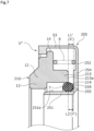
FIG. 2 is a cross-sectional view showing a seal ring unit including a seal ring, a casing, a spring, and an O-ring in the first embodiment. -
FIG. 3 is a front view showing the seal ring unit including the seal ring, the casing, the spring, and the O-ring in the first embodiment. -
FIG. 4A is a cross-sectional view showing a state in which the spring and the O-ring are accommodated in the casing in the first embodiment,FIG. 4B is a cross-sectional view showing a state in which the seal ring is press-inserted into the casing in the first embodiment, andFIG. 4C is a cross-sectional view showing a state in which the seal ring is rotated clockwise in the first embodiment. -
FIG. 5A is a front view showing a state in which the spring and the O-ring are accommodated in the casing in the first embodiment,FIG. 5B is a front view showing a state in which the seal ring is press-inserted into the casing in the first embodiment, andFIG. 5C is a front view showing a state in which the seal ring is rotated clockwise in the first embodiment. -
FIG. 6 is a cross-sectional view showing a seal ring unit including a seal ring, a casing, a spring, and an O-ring of a first modified example of the first embodiment. -
FIG. 7 is a cross-sectional view showing a seal ring unit including a seal ring, a casing, a spring, and an O-ring of a mechanical seal according to a second embodiment of the present invention. - Modes for carrying out a mechanical seal according to the present invention will be described below on the basis of the embodiments.
- A mechanical seal according to a first embodiment of the present invention will be described with reference to
FIGS. 1 to 5 . Additionally, in this embodiment, an outer diameter side of a seal ring will be described as a sealed fluid side (i.e., high pressure side) and an inner diameter side thereof will be described as an atmosphere side (i.e., low pressure side). Additionally, a sliding surface side of the seal ring will be described as a front side. - A
mechanical seal 1 shown inFIG. 1 is of an inside type in which an inner space S1 is formed on the inner diameter side of the sliding surface, an outer space S2 is formed on the outer diameter side of the sliding surface, a sealed fluid F leaking from the outer diameter side to the inner diameter side of the sliding surface is sealed, and an atmosphere A passes through an inner space S1. Additionally, in this embodiment, an example in which the sealed fluid F is a high-pressure liquid and the atmosphere A is a gas having a lower pressure than that of the sealed fluid F is illustrated. - The
mechanical seal 1 mainly includes anannular mating ring 20 and a seal ring unit U. Themating ring 20 is provided on arotating shaft 3 to be rotatable together with therotating shaft 3 through a sleeve 2. The seal ring unit U is fixed to ahousing 4 of an attached device. - The seal ring unit U includes a
casing 5 which is fixed to thehousing 4, aseal ring 10 which is provided in thecasing 5 not to be rotatable and to be axially movable, aspring 6 which is an urging member disposed between thecasing 5 and theseal ring 10, and an O-ring 7 which is a secondary seal sealing a gap between thecasing 5 and theseal ring 10. - When the
seal ring 10 is axially urged by thespring 6, a slidingsurface 11 of theseal ring 10 and a slidingsurface 21 of themating ring 20 slide closely with each other. - The
seal ring 10 and themating ring 20 are typically formed of SiC (as an example of hard material) or a combination of SiC and carbon (as an example of soft material), but the present invention is not limited thereto. The sliding material which can be used as the sliding material for the mechanical seal can be applied. In addition, examples of SiC include materials composed of two or more types of phases having different components and compositions, for example, SiC in which graphite particles are dispersed, reaction sintered SiC composed of SiC and Si, SiC-TiC, SiC-TiN, and the like as well as sintered bodies using boron, aluminum, carbon, and the like as sintering aids and examples of the carbon include resin-molded carbon, sintered carbon, and the like as well as carbon which is a mixture of carbonaceous and graphite. In addition to the above-described sliding materials, metal materials, resin materials, surface modification materials (e.g., coating materials), composite materials, and the like can also be applied. -
FIG. 2 shows the seal ring unit U as a single unit. As will be described in detail later, since the seal ring unit U can be maintained in a unit state without separating theseal ring 10, thecasing 5, thespring 6, and the O-ring 7, they can be carried for each seal ring unit U. - As shown in
FIG. 2 , theseal ring 10 includes abase portion 12, afront extension portion 13 which extends from thebase portion 12 toward the front side, an outerdiameter extension portion 14 which extends from thebase portion 12 toward the outer diameter side, and a cylindricalback extension portion 15 which is an extension portion extending from thebase portion 12 toward the back side, that is, the side opposite to themating ring 20. The slidingsurface 11 is provided on the front side of thefront extension portion 13. - As shown in
FIG. 2 , thecasing 5 includes a cylindricalinner diameter portion 51 which is inserted through theseal ring 10, anannular back wall 52 which extends from the back side end portion of theinner diameter portion 51 toward the outer diameter direction and overlaps with the seal ring in the axial direction, and a cylindricalouter diameter portion 53 which extends in the axial direction from the outer diameter side end portion of theback wall 52 toward themating ring 20. - An
annular step portion 54 which protrudes toward the front side is provided at the inner diameter end portion, that is, the inner corner portion of theback wall 52 and thestep portion 54 is integrally molded with theback wall 52 and theinner diameter portion 51. Further, afront wall 55 which is a regulation wall regulating the movement of the O-ring 7 toward the side opposite to themating ring 20 in the axial direction is formed on the front side of thestep portion 54. In addition, although it has been described such that thestep portion 54 has an annular shape, the step portions may be arranged at a plurality of positions to be divided in the circumferential direction. - A pop-
out regulation portion 56 which extends in the inner diameter direction is provided at the front end of theouter diameter portion 53. Further, as shown inFIG. 3 , the pop-out regulation portion 56 is provided at three positions equally on the circumference on the front side of theouter diameter portion 53 of thecasing 5 and has a substantially semi-circular shape smaller than anotch 17 of theseal ring 10. Further, for convenience of description, in the front view ofFIG. 3 or the like, theouter diameter portion 53 of thecasing 5 and a dynamicpressure generation groove 11a of the slidingsurface 11 of theseal ring 10 are indicated by dots. - As shown in
FIG. 2 , thespring 6 is disposed between aback surface 14a and theback wall 52 while being axially compressed due to the contact with theback surface 14a of the outerdiameter extension portion 14 of theseal ring 10 and aninner surface 52a of theback wall 52 of thecasing 5 on the outer diameter side in relation to theback extension portion 15 of theseal ring 10. In addition, the type and shape of thespring 6 are not particularly limited. - Further, as shown in
FIG. 2 , the O-ring 7 is formed as an elastic member having a circular cross-section and is disposed between an innerperipheral surface 18 and an outerperipheral surface 51a in a radial press-contact state due to the contact with the innerperipheral surface 18 of theback extension portion 15 of theseal ring 10 and the outerperipheral surface 51a of theinner diameter portion 51 of thecasing 5. - As shown in
FIG. 3 , a plurality of the dynamicpressure generation grooves 11a are formed on the inner diameter side of the slidingsurface 11. Additionally, the dynamicpressure generation groove 11a is not limited to the arc shape and may have a different form such as a Rayleigh step or dimple. Further, the dynamicpressure generation groove 11a may be not formed on the slidingsurface 11. - As shown in
FIG. 3 , theanti-rotation groove 16 and thenotch 17 which are disposed at three positions equally in the circumferential direction are formed at anouter edge 14b of the outerdiameter extension portion 14. - The
notch 17 is formed in a shape notched in an arc shape to penetrate in the axial direction at an adjacent position of theanti-rotation groove 16 in the clockwise direction. - Specifically, the
anti-rotation groove 16 includes abottom surface 16a and ananti-rotation wall 16b. Thebottom surface 16a is recessed one step from an outerdiameter side surface 14c of the outerdiameter extension portion 14 and extends by a predetermined dimension in the circumferential direction. Theanti-rotation wall 16b extends vertically from the counterclockwise side edge of thebottom surface 16a toward the outerdiameter side surface 14c. - Further, the
spring 6 is located on the outer diameter in relation to the O-ring 7 and is disposed to partially overlap with the O-ring 7 in the radial direction. Further, the O-ring 7 comes into contact with thefront wall 55 of thestep portion 54 of thecasing 5. - As shown in
FIG. 2 , in the single seal ring unit U, thebottom surface 16a of theanti-rotation groove 16 of the outerdiameter extension portion 14 of theseal ring 10 to be described later is in contact with theback surface 56a of the pop-out regulation portion 56 of theouter diameter portion 53 of the casing 5 (hereinafter, referred to as a natural state). - When the seal ring unit U is in the natural state, an axial separation dimension X from the
back surface 15a of theback extension portion 15 to thefront wall 55 of thestep portion 54 is smaller than a radius Y which is a half of the axial dimension of the O-ring 7 (i.e., X < Y). Therefore, a gap between the innerperipheral surface 18 of theback extension portion 15 of theseal ring 10 and the outerperipheral surface 51a of theinner diameter portion 51 of thecasing 5 can be reliably sealed by the O-ring 7 which is a secondary seal. - In other words, an axial separation dimension L1 from the
back surface 15a of theback extension portion 15 of theseal ring 10 to theinner surface 52a of theback wall 52 of thecasing 5 is shorter than an axial separation dimension L2 from the axial center of the O-ring 7, that is, the axial center position exhibiting the sealing performance of the O-ring 7 to theinner surface 52a of theback wall 52 of the casing 5 (i.e., L1 < L2). - When the seal ring unit U is in the natural state, the
seal ring 10 is located on the frontmost side of the range of motion in the axial direction, that is, L1 is the maximum. Since the O-ring 7 comes into contact with the innerperipheral surface 18 of theback extension portion 15 of theseal ring 10 in that state, the seal ring unit U in the natural state is stable in the unitized state. Therefore, it is easy to carry the seal ring unit U. - Further, a gap between the
casing 5 and theseal ring 10 can be reliably sealed by the O-ring 7 while themechanical seal 1 is assembled to therotating shaft 3 and thehousing 4 as will be described later. - Next, the assembly of the seal ring unit U will be described. As shown in
FIGS. 4A and5A , thespring 6 and the O-ring 7 are first arranged inside thecasing 5 while being separated from each other by a predetermined dimension in the radial direction. The O-ring 7 is externally fitted to theinner diameter portion 51 of thecasing 5 while coming into contact with thefront wall 55 of thestep portion 54 of thecasing 5. - Next, as shown in
FIGS. 4B and5B , theseal ring 10 is inserted into thecasing 5. - Specifically, as shown in
FIG. 5B , theseal ring 10 is moved toward the back side after the circumferential position of theseal ring 10 is adjusted so that thenotch 17 of the outerdiameter extension portion 14 of theseal ring 10 overlaps with the pop-out regulation portion 56 of theouter diameter portion 53 of thecasing 5. - Then, the
seal ring 10 is further moved toward the back side against the axial urging force due to the compression of thespring 6 while the front end portion of thespring 6 comes into contact with theback surface 14a of the outerdiameter extension portion 14 of theseal ring 10 and thebottom surface 16a of theanti-rotation groove 16 of the outerdiameter extension portion 14 of theseal ring 10 is moved to reach the back side in relation to theback surface 56a of the pop-out regulation portion 56 of the casing 5 (seeFIG. 4B ). - At this time, the inner
peripheral surface 18 of theback extension portion 15 of theseal ring 10 slides on the O-ring 7 and theback extension portion 15 is inserted between thespring 6 and the O-ring 7 in the radial direction. - Next, as shown in
FIGS. 4C and5C , theseal ring 10 is rotated clockwise while maintaining the amount of pressing theseal ring 10 toward the back side. By this rotation, the pop-out regulation portion 56 of thecasing 5 moves inside theanti-rotation groove 16 of theseal ring 10 and theback surface 56a of the pop-out regulation portion 56 faces thebottom surface 16a of theanti-rotation groove 16. In addition, the excessive rotation of the pop-out regulation portion 56 can be prevented by theanti-rotation wall 16b of theanti-rotation groove 16. - Then, the
seal ring 10 is pressed back to the front side by the urging force of thespring 6 by releasing the pressed state to the back side of theseal ring 10, but when thebottom surface 16a of theanti-rotation groove 16 of theseal ring 10 comes into contact with theback surface 56a of the pop-out regulation portion 56 of thecasing 5, theseal ring 10 is regulated from popping out of the casing 5 (seeFIGS. 2 and3 ). At this time, the seal ring unit U is in the natural state. - Next, the assembly of the
mechanical seal 1 to therotating shaft 3 and thehousing 4 will be described. Referring toFIG. 1 , themating ring 20 is first fixed to therotating shaft 3 by using the sleeve 2. Next, thecasing 5 of the seal ring unit U is fixed to a predetermined position of thehousing 4. - Then, the
rotating shaft 3 is inserted through the inner diameter hole of the seal ring unit U, themating ring 20 fixed to therotating shaft 3 is brought into contact with theseal ring 10, and the axial position of therotating shaft 3 is adjusted and fixed so that therotating shaft 3 is further pressed toward the back side against the urging force of thespring 6. - At this time, the
bottom surface 16a of theanti-rotation groove 16 of the outerdiameter extension portion 14 of theseal ring 10 is separated from theback surface 56a of the pop-out regulation portion 56 of theouter diameter portion 53 of thecasing 5 toward the back side and theseal ring 10 is axially pressed toward themating ring 20 by thespring 6. Therefore, it is possible to maintain the sliding contact state between the slidingsurfaces surfaces seal ring 10 and themating ring 20 are abraded. In addition, the assembly procedure of themechanical seal 1 is not limited thereto. - Accordingly, since it is possible to assembling the
mechanical seal 1 to therotating shaft 3 and thehousing 4 without disassembling the seal ring unit U, it is possible to simplify the assembly of themechanical seal 1. - Further, since the
anti-rotation wall 16b of theanti-rotation groove 16 of theseal ring 10 comes into contact with the pop-out regulation portion 56 of thecasing 5 during the rotation of themating ring 20 when theseal ring 10 rotates together in the rotation direction of themating ring 20, that is, clockwise by referring toFIG. 3 , the idle rotation of theseal ring 10 can be prevented. - A first modified example of the first embodiment will be described. The same components as those shown in the above-described embodiment are designated by the same reference numerals, and duplicate description will be omitted. As shown in
FIG. 6 , acasing 105 constituting a seal ring unit U' includes aninner diameter portion 151, aback wall 152, and anouter diameter portion 53. Thecasing 105 is provided with anannular regulation wall 155 which extends from theinner diameter portion 151 toward the outer diameter side and faces theback wall 152. - In this way, since the
casing 105 is provided with theregulation wall 155 which regulates the movement of the O-ring 7 toward the back side, it is possible to reliably seal a gap between thecasing 105 and theseal ring 10 by the O-ring 7. Further, the O-ring 7 is easily positioned to thecasing 5. - As described above, since the
casing 5 is provided with thefront wall 55, a member such as a spring holder is not necessary and the axial dimension of themechanical seal 1 can be shortened. Further, since an axial dimension X between theseal ring 10 and thefront wall 55 is equal to or less than the radius Y of the O-ring 7 while theseal ring 10 and the pop-out regulation portion 56 come into contact with each other, a gap between theseal ring 10 and thecasing 5 can be reliably sealed by the O-ring 7 when theseal ring 10 and thecasing 5 are assembled and theseal ring 10 is held at a regulation position not to pop out of thecasing 5. - Further, since the
spring 6 is disposed to partially overlap with the O-ring 7 at a different position in the radial direction, thespring 6 and the O-ring 7 do not interfere with each other. Accordingly, it is possible to shorten the axial dimension of the seal ring unit U of themechanical seal 1. - Further, the
back extension portion 15 which extends in the axial direction is provided on the back side of theseal ring 10. Theback extension portion 15 divides the seal ring so that the O-ring 7 is disposed on the inner diameter side and thespring 6 is disposed on the outer diameter side. Accordingly, it is possible to reliably seal a gap between theseal ring 10 and thecasing 5 by the O-ring 7 by reliably preventing the interference between thespring 6 and the O-ring 7. - Further, the regulation wall is the
front wall 55 of thestep portion 54 which is integrally molded to extend from theback wall 52 of thecasing 5 toward the front side. The O-ring 7 is disposed on the front side of theback wall 52 while coming into contact with thefront wall 55. Accordingly, it is possible to reliably seal a gap between thecasing 5 and theseal ring 10 by the O-ring 7 while ensuring the axial length of the space for disposing thespring 6. Further, since thestep portion 54 is integrally molded with thecasing 5, the regulation wall can have a simple configuration. - Further, it is possible to reliably prevent the
back extension portion 15 and theback wall 52 from biting the O-ring 7 when theback extension portion 15 of theseal ring 10 approaches theback wall 52 of thecasing 5. - Further, since the
spring 6 directly comes into contact with theseal ring 10 and thecasing 5, it is possible to decrease the number of parts of the seal ring unit U of themechanical seal 1. Accordingly, it is possible to shorten the axial dimension of the seal ring unit U and to reduce the integrated tolerance of parts. - Next, a mechanical seal according to a second embodiment of the present invention will be described with reference to
FIG. 7 . In addition, the description of the overlapping configuration in the same configuration as that of the above-described embodiment will be omitted. - As shown in
FIG. 7 , aseal ring 210 constituting a seal ring unit U" includes abase portion 12, afront extension portion 13, an outerdiameter extension portion 14, and aback extension portion 215 as an extension portion. Aback surface 215a of theback extension portion 215 and an innerperipheral surface 218 constitute acorner portion 219. - Further, a
casing 205 constituting the seal ring unit U" includes aninner diameter portion 251, aback wall 252, and anouter diameter portion 53. Astep portion 254 which slightly extends toward the front side is provided on the inner diameter side of theback wall 252 and afront wall 255 which is a regulation wall is formed in front of thestep portion 254. Thestep portion 254 is provided in the radial direction from the inner diameter end of theback wall 252 to the outer diameter end of theback extension portion 215 of theseal ring 210. - When the seal ring unit U" is in the natural state, an axial separation dimension X' from the
back surface 215a of theback extension portion 215 to thefront wall 255 of thestep portion 254 is the same as a radius Y' which is a half of the axial dimension of the O-ring 7 (X' = Y'). Therefore, a gap between the innerperipheral surface 218 of theback extension portion 215 of theseal ring 210 and an outerperipheral surface 251a of theinner diameter portion 251 of thecasing 205 can be reliably sealed by the O-ring 7 which is the secondary seal. Additionally, L1' and L2' corresponding to the axial separation dimensions L1 and L2 of the first embodiment are respectively the same as the axial separation dimension X' and the radius Y' (i.e., L1' = X', L2' = Y'). - When the seal ring unit U'' is in the natural state, the
seal ring 210 is located on the frontmost side of the axial range of motion, that is, L1' is the maximum. In that state, the axial center of the O-ring 7 reliably comes into contact with thecorner portion 219 of theseal ring 210. Accordingly, a gap between thecasing 205 and theseal ring 210 can be reliably sealed by the O-ring 7 in a state in which the seal ring unit U'' is assembled to thehousing 4, that is, theback surface 215a is close to thefront wall 255, that is, the axial center of the O-ring 7 is disposed on the front side in relation to theback surface 215a. - Although examples of the present invention have been described above with reference to the drawings, the specific configuration is not limited to these examples and is included in the present invention even if there are changes or additions within the scope of the present invention.
- For example, in the first and second embodiments, an example of an inside type that seals the sealed fluid F leaking from the outer diameter side to the inner diameter side of the sliding surface has been illustrated, but an outside type that seals the sealed fluid F leaking from the inner diameter side to the outer diameter side of the sliding surface may be used.
- Further, although it has been described such that the anti-rotation groove, the notch, and the pop-out regulation portion are formed at three places equally on the circumference, the present invention is not limited thereto. For example, the anti-rotation groove, the notch, and the pop-out regulation portion may be formed at a plurality of positions equally on the circumference and may be formed unequally on the circumference if the anti-rotation groove, the notch, and the pop-out regulation portion respectively correspond to each other on the circumference.
- Further, although it has been described such that the notch and the pop-out regulation portion have an arc shape, but the present invention is not limited thereto. For example, the notch and the pop-out regulation portion may have a rectangular shape.
- Further, although it has been described such that the sealed fluid is a high-pressure liquid, the present invention is not limited thereto. For example, the sealed fluid may be a gas, a low-pressure liquid, or a mist obtained by mixing a liquid and a gas.
- Further, the step portion and the regulation wall may be separated from the casing.
- Further, the back extension portion may be separated from the seal ring.
-
- 1
- Mechanical seal
- 3
- Rotating shaft
- 5
- Casing
- 6
- Spring (urging member)
- 7
- O-ring (secondary seal)
- 10
- Seal ring
- 15
- Back extension portion (extension portion)
- 20
- Mating ring
- 52
- Back wall
- 54
- Step portion
- 55
- Front wall (regulation wall)
- 105
- Casing
- 152
- Back wall
- 155
- Regulation wall
- 205
- Casing
- 210
- Seal ring
- 215
- Back extension portion (extension portion)
- 252
- Back wall
- 254
- Step portion
- 255
- Front wall (regulation wall)
- A
- Atmosphere
- F
- Sealed fluid
- L1, L2
- Axial separation dimension
- L1', L2'
- Axial separation dimension
- S1
- Inner space
- S2
- Outer space
- U, U', U"
- Seal ring unit
- X, X'
- Axial separation dimension
- Y, Y'
- Radius of O-ring (half of secondary seal in axial dimension)
Claims (4)
- A mechanical seal, comprising:a mating ring;a seal ring which slides relative to the mating ring;a casing which includes a pop-out regulation portion supporting the seal ring not to be rotatable and to be axially movable and coming into contact with the seal ring to regulate the seal ring from popping out toward the mating ring;an urging member that is disposed between the seal ring and a back wall of the casing axially overlapping with the seal ring and axially urges the seal ring toward the mating ring; anda secondary seal which is formed in an annular shape and which seals a gap between the casing and the seal ring while being radially press-inserted thereinto,wherein the casing includes a regulation wall which regulates the secondary seal from moving toward a side opposite to the mating ring in an axial direction, andwherein an axial dimension between the seal ring and the regulation wall is equal to or less than a half of an axial dimension of the secondary seal while the seal ring and the pop-out regulation portion are in contact with each other.
- The mechanical seal according to claim 1,wherein an extension portion extending in the axial direction is provided on a back side of the seal ring, andthe urging member and the secondary seal are respectively arranged on an inner diameter side and an outer diameter side of the extension portion.
- The mechanical seal according to claim 1 or 2,
wherein the regulation wall is a front wall of a step portion integrally molded to protrude from the back wall toward the mating ring. - The mechanical seal according to any one of claims 1 to 3,
wherein the urging member directly comes into contact with the seal ring and the casing.
Applications Claiming Priority (2)
| Application Number | Priority Date | Filing Date | Title |
|---|---|---|---|
| JP2020107548 | 2020-06-23 | ||
| PCT/JP2021/022550 WO2021261317A1 (en) | 2020-06-23 | 2021-06-14 | Mechanical seal |
Publications (2)
| Publication Number | Publication Date |
|---|---|
| EP4170206A1 true EP4170206A1 (en) | 2023-04-26 |
| EP4170206A4 EP4170206A4 (en) | 2024-07-03 |
Family
ID=79281183
Family Applications (1)
| Application Number | Title | Priority Date | Filing Date |
|---|---|---|---|
| EP21828025.3A Withdrawn EP4170206A4 (en) | 2020-06-23 | 2021-06-14 | MECHANICAL JOINT |
Country Status (5)
| Country | Link |
|---|---|
| US (1) | US12060944B2 (en) |
| EP (1) | EP4170206A4 (en) |
| JP (1) | JP7608032B2 (en) |
| CN (1) | CN115917193A (en) |
| WO (1) | WO2021261317A1 (en) |
Cited By (1)
| Publication number | Priority date | Publication date | Assignee | Title |
|---|---|---|---|---|
| EP4172515A1 (en) * | 2020-06-30 | 2023-05-03 | John Crane UK Ltd. | Mechanical seal assembly and method of assembly of a mechanical seal |
Families Citing this family (1)
| Publication number | Priority date | Publication date | Assignee | Title |
|---|---|---|---|---|
| WO2025057908A1 (en) * | 2023-09-11 | 2025-03-20 | イーグル工業株式会社 | Sliding component |
Family Cites Families (17)
| Publication number | Priority date | Publication date | Assignee | Title |
|---|---|---|---|---|
| US2856219A (en) * | 1954-07-07 | 1958-10-14 | Victor Mfg & Gasket Co | Fluid seal |
| JPS6322326Y2 (en) | 1981-01-24 | 1988-06-20 | ||
| JPS59100148U (en) | 1982-08-10 | 1984-07-06 | 株式会社荒井製作所 | Mechanical seal for high speed rotation |
| JPS59100148A (en) | 1982-11-30 | 1984-06-09 | Yokohama Rubber Co Ltd:The | Rubber composition |
| IT208699Z2 (en) * | 1986-07-18 | 1988-05-28 | Meccanotecnica Umbra Srl | SEAL FOR CENTRIFUGAL AND ROTARY HYDRAULIC PUMPS OF THE TYPE WITH SLOPE AND SLIDING COUNTER OF REDUCED AXIAL OVERALL DIMENSION |
| EP1213516A1 (en) | 2000-12-08 | 2002-06-12 | M.E.F. Financing Establishment | Mechanical seal |
| JP2002267026A (en) | 2001-03-06 | 2002-09-18 | Eagle Ind Co Ltd | Seal device of mechanical seal and its assembling method |
| JP3933469B2 (en) * | 2001-12-28 | 2007-06-20 | イーグル工業株式会社 | Mechanical seal device |
| JP4734171B2 (en) * | 2006-05-12 | 2011-07-27 | 株式会社神戸製鋼所 | mechanical seal |
| JP2008185082A (en) * | 2007-01-29 | 2008-08-14 | Ihi Corp | Gas seal device |
| JP2011074931A (en) | 2009-09-29 | 2011-04-14 | Ihi Corp | Sealing device for combustible gas compressor |
| JP6573631B2 (en) | 2014-12-01 | 2019-09-11 | イーグル工業株式会社 | Mechanical seal device |
| JP6595589B2 (en) * | 2015-05-20 | 2019-10-23 | イーグル工業株式会社 | Sliding parts |
| JP6678170B2 (en) * | 2015-05-21 | 2020-04-08 | イーグル工業株式会社 | Sliding parts |
| WO2018051867A1 (en) * | 2016-09-14 | 2018-03-22 | イーグル工業株式会社 | Mechanical seal |
| WO2019059197A1 (en) * | 2017-09-20 | 2019-03-28 | イーグル工業株式会社 | Mecanical seal |
| WO2019181671A1 (en) * | 2018-03-23 | 2019-09-26 | イーグル工業株式会社 | Mechanical seal |
-
2021
- 2021-06-14 US US18/008,124 patent/US12060944B2/en active Active
- 2021-06-14 WO PCT/JP2021/022550 patent/WO2021261317A1/en not_active Ceased
- 2021-06-14 CN CN202180039753.1A patent/CN115917193A/en active Pending
- 2021-06-14 JP JP2022531810A patent/JP7608032B2/en active Active
- 2021-06-14 EP EP21828025.3A patent/EP4170206A4/en not_active Withdrawn
Cited By (2)
| Publication number | Priority date | Publication date | Assignee | Title |
|---|---|---|---|---|
| EP4172515A1 (en) * | 2020-06-30 | 2023-05-03 | John Crane UK Ltd. | Mechanical seal assembly and method of assembly of a mechanical seal |
| EP4172515B1 (en) * | 2020-06-30 | 2025-09-03 | John Crane UK Ltd. | Mechanical seal assembly and method of assembly of a mechanical seal |
Also Published As
| Publication number | Publication date |
|---|---|
| EP4170206A4 (en) | 2024-07-03 |
| JPWO2021261317A1 (en) | 2021-12-30 |
| CN115917193A (en) | 2023-04-04 |
| WO2021261317A1 (en) | 2021-12-30 |
| US12060944B2 (en) | 2024-08-13 |
| US20230279950A1 (en) | 2023-09-07 |
| JP7608032B2 (en) | 2025-01-06 |
Similar Documents
| Publication | Publication Date | Title |
|---|---|---|
| US12060944B2 (en) | Mechanical seal | |
| JP6795586B2 (en) | mechanical seal | |
| US10900568B2 (en) | Sealing structure | |
| EP1723354B1 (en) | Self-energized gasket and manufacturing method therefor | |
| US11396947B2 (en) | Face seal with welded bellows | |
| US2729478A (en) | Packing construction | |
| CN111094814B (en) | Mechanical sealing element | |
| US6322079B1 (en) | Face seal | |
| JP5797264B2 (en) | mechanical seal | |
| CN108488384A (en) | conical surface adaptive mechanical sealing device | |
| JP2001317637A (en) | Shaft seal mechanism for compressor by mechanical seal | |
| US3761100A (en) | Fluid seal assembly | |
| JP6991943B2 (en) | Split mechanical seal | |
| JP7353721B2 (en) | Secondary seal for mechanical seals | |
| JP2004332920A (en) | Sealing structure and end-face seal | |
| EP4571152A1 (en) | Secondary seal | |
| JP2024003623A (en) | mechanical seal | |
| JP7455467B2 (en) | Mechanical seal and elastic member used therein | |
| JPH1182751A (en) | Sealing device | |
| JP7234073B2 (en) | double mechanical seal | |
| JP6991947B2 (en) | Shaft sealing device | |
| EP4534875A1 (en) | Mechanical tool | |
| JP2001132852A (en) | Mechanical seal | |
| WO2026058827A1 (en) | Mechanical seal | |
| JP2025076054A (en) | Mechanical seal |
Legal Events
| Date | Code | Title | Description |
|---|---|---|---|
| STAA | Information on the status of an ep patent application or granted ep patent |
Free format text: STATUS: THE INTERNATIONAL PUBLICATION HAS BEEN MADE |
|
| PUAI | Public reference made under article 153(3) epc to a published international application that has entered the european phase |
Free format text: ORIGINAL CODE: 0009012 |
|
| STAA | Information on the status of an ep patent application or granted ep patent |
Free format text: STATUS: REQUEST FOR EXAMINATION WAS MADE |
|
| 17P | Request for examination filed |
Effective date: 20221209 |
|
| AK | Designated contracting states |
Kind code of ref document: A1 Designated state(s): AL AT BE BG CH CY CZ DE DK EE ES FI FR GB GR HR HU IE IS IT LI LT LU LV MC MK MT NL NO PL PT RO RS SE SI SK SM TR |
|
| DAV | Request for validation of the european patent (deleted) | ||
| DAX | Request for extension of the european patent (deleted) | ||
| A4 | Supplementary search report drawn up and despatched |
Effective date: 20240603 |
|
| RIC1 | Information provided on ipc code assigned before grant |
Ipc: F16J 15/38 20060101ALI20240527BHEP Ipc: F16J 15/34 20060101AFI20240527BHEP |
|
| STAA | Information on the status of an ep patent application or granted ep patent |
Free format text: STATUS: EXAMINATION IS IN PROGRESS |
|
| 17Q | First examination report despatched |
Effective date: 20250507 |
|
| STAA | Information on the status of an ep patent application or granted ep patent |
Free format text: STATUS: THE APPLICATION HAS BEEN WITHDRAWN |
|
| 18W | Application withdrawn |
Effective date: 20251001 |