EP4170174A1 - Rotary compressor - Google Patents
Rotary compressor Download PDFInfo
- Publication number
- EP4170174A1 EP4170174A1 EP22180645.8A EP22180645A EP4170174A1 EP 4170174 A1 EP4170174 A1 EP 4170174A1 EP 22180645 A EP22180645 A EP 22180645A EP 4170174 A1 EP4170174 A1 EP 4170174A1
- Authority
- EP
- European Patent Office
- Prior art keywords
- suction
- cylinder
- compression space
- guide portion
- suction passage
- Prior art date
- Legal status (The legal status is an assumption and is not a legal conclusion. Google has not performed a legal analysis and makes no representation as to the accuracy of the status listed.)
- Granted
Links
Images







Classifications
-
- F—MECHANICAL ENGINEERING; LIGHTING; HEATING; WEAPONS; BLASTING
- F04—POSITIVE - DISPLACEMENT MACHINES FOR LIQUIDS; PUMPS FOR LIQUIDS OR ELASTIC FLUIDS
- F04C—ROTARY-PISTON, OR OSCILLATING-PISTON, POSITIVE-DISPLACEMENT MACHINES FOR LIQUIDS; ROTARY-PISTON, OR OSCILLATING-PISTON, POSITIVE-DISPLACEMENT PUMPS
- F04C18/00—Rotary-piston pumps specially adapted for elastic fluids
- F04C18/30—Rotary-piston pumps specially adapted for elastic fluids having the characteristics covered by two or more of groups F04C18/02, F04C18/08, F04C18/22, F04C18/24, F04C18/48, or having the characteristics covered by one of these groups together with some other type of movement between co-operating members
- F04C18/34—Rotary-piston pumps specially adapted for elastic fluids having the characteristics covered by two or more of groups F04C18/02, F04C18/08, F04C18/22, F04C18/24, F04C18/48, or having the characteristics covered by one of these groups together with some other type of movement between co-operating members having the movement defined in group F04C18/08 or F04C18/22 and relative reciprocation between the co-operating members
- F04C18/356—Rotary-piston pumps specially adapted for elastic fluids having the characteristics covered by two or more of groups F04C18/02, F04C18/08, F04C18/22, F04C18/24, F04C18/48, or having the characteristics covered by one of these groups together with some other type of movement between co-operating members having the movement defined in group F04C18/08 or F04C18/22 and relative reciprocation between the co-operating members with vanes reciprocating with respect to the outer member
- F04C18/3562—Rotary-piston pumps specially adapted for elastic fluids having the characteristics covered by two or more of groups F04C18/02, F04C18/08, F04C18/22, F04C18/24, F04C18/48, or having the characteristics covered by one of these groups together with some other type of movement between co-operating members having the movement defined in group F04C18/08 or F04C18/22 and relative reciprocation between the co-operating members with vanes reciprocating with respect to the outer member the inner and outer member being in contact along one line or continuous surfaces substantially parallel to the axis of rotation
-
- F—MECHANICAL ENGINEERING; LIGHTING; HEATING; WEAPONS; BLASTING
- F04—POSITIVE - DISPLACEMENT MACHINES FOR LIQUIDS; PUMPS FOR LIQUIDS OR ELASTIC FLUIDS
- F04C—ROTARY-PISTON, OR OSCILLATING-PISTON, POSITIVE-DISPLACEMENT MACHINES FOR LIQUIDS; ROTARY-PISTON, OR OSCILLATING-PISTON, POSITIVE-DISPLACEMENT PUMPS
- F04C18/00—Rotary-piston pumps specially adapted for elastic fluids
- F04C18/30—Rotary-piston pumps specially adapted for elastic fluids having the characteristics covered by two or more of groups F04C18/02, F04C18/08, F04C18/22, F04C18/24, F04C18/48, or having the characteristics covered by one of these groups together with some other type of movement between co-operating members
- F04C18/34—Rotary-piston pumps specially adapted for elastic fluids having the characteristics covered by two or more of groups F04C18/02, F04C18/08, F04C18/22, F04C18/24, F04C18/48, or having the characteristics covered by one of these groups together with some other type of movement between co-operating members having the movement defined in group F04C18/08 or F04C18/22 and relative reciprocation between the co-operating members
- F04C18/344—Rotary-piston pumps specially adapted for elastic fluids having the characteristics covered by two or more of groups F04C18/02, F04C18/08, F04C18/22, F04C18/24, F04C18/48, or having the characteristics covered by one of these groups together with some other type of movement between co-operating members having the movement defined in group F04C18/08 or F04C18/22 and relative reciprocation between the co-operating members with vanes reciprocating with respect to the inner member
- F04C18/3441—Rotary-piston pumps specially adapted for elastic fluids having the characteristics covered by two or more of groups F04C18/02, F04C18/08, F04C18/22, F04C18/24, F04C18/48, or having the characteristics covered by one of these groups together with some other type of movement between co-operating members having the movement defined in group F04C18/08 or F04C18/22 and relative reciprocation between the co-operating members with vanes reciprocating with respect to the inner member the inner and outer member being in contact along one line or continuous surface substantially parallel to the axis of rotation
- F04C18/3445—Rotary-piston pumps specially adapted for elastic fluids having the characteristics covered by two or more of groups F04C18/02, F04C18/08, F04C18/22, F04C18/24, F04C18/48, or having the characteristics covered by one of these groups together with some other type of movement between co-operating members having the movement defined in group F04C18/08 or F04C18/22 and relative reciprocation between the co-operating members with vanes reciprocating with respect to the inner member the inner and outer member being in contact along one line or continuous surface substantially parallel to the axis of rotation the vanes having the form of rollers, slippers or the like
-
- F—MECHANICAL ENGINEERING; LIGHTING; HEATING; WEAPONS; BLASTING
- F01—MACHINES OR ENGINES IN GENERAL; ENGINE PLANTS IN GENERAL; STEAM ENGINES
- F01C—ROTARY-PISTON OR OSCILLATING-PISTON MACHINES OR ENGINES
- F01C21/00—Component parts, details or accessories not provided for in groups F01C1/00 - F01C20/00
- F01C21/10—Outer members for co-operation with rotary pistons; Casings
- F01C21/104—Stators; Members defining the outer boundaries of the working chamber
- F01C21/108—Stators; Members defining the outer boundaries of the working chamber with an axial surface, e.g. side plates
-
- F—MECHANICAL ENGINEERING; LIGHTING; HEATING; WEAPONS; BLASTING
- F04—POSITIVE - DISPLACEMENT MACHINES FOR LIQUIDS; PUMPS FOR LIQUIDS OR ELASTIC FLUIDS
- F04C—ROTARY-PISTON, OR OSCILLATING-PISTON, POSITIVE-DISPLACEMENT MACHINES FOR LIQUIDS; ROTARY-PISTON, OR OSCILLATING-PISTON, POSITIVE-DISPLACEMENT PUMPS
- F04C18/00—Rotary-piston pumps specially adapted for elastic fluids
- F04C18/30—Rotary-piston pumps specially adapted for elastic fluids having the characteristics covered by two or more of groups F04C18/02, F04C18/08, F04C18/22, F04C18/24, F04C18/48, or having the characteristics covered by one of these groups together with some other type of movement between co-operating members
- F04C18/34—Rotary-piston pumps specially adapted for elastic fluids having the characteristics covered by two or more of groups F04C18/02, F04C18/08, F04C18/22, F04C18/24, F04C18/48, or having the characteristics covered by one of these groups together with some other type of movement between co-operating members having the movement defined in group F04C18/08 or F04C18/22 and relative reciprocation between the co-operating members
- F04C18/344—Rotary-piston pumps specially adapted for elastic fluids having the characteristics covered by two or more of groups F04C18/02, F04C18/08, F04C18/22, F04C18/24, F04C18/48, or having the characteristics covered by one of these groups together with some other type of movement between co-operating members having the movement defined in group F04C18/08 or F04C18/22 and relative reciprocation between the co-operating members with vanes reciprocating with respect to the inner member
- F04C18/3441—Rotary-piston pumps specially adapted for elastic fluids having the characteristics covered by two or more of groups F04C18/02, F04C18/08, F04C18/22, F04C18/24, F04C18/48, or having the characteristics covered by one of these groups together with some other type of movement between co-operating members having the movement defined in group F04C18/08 or F04C18/22 and relative reciprocation between the co-operating members with vanes reciprocating with respect to the inner member the inner and outer member being in contact along one line or continuous surface substantially parallel to the axis of rotation
- F04C18/3442—Rotary-piston pumps specially adapted for elastic fluids having the characteristics covered by two or more of groups F04C18/02, F04C18/08, F04C18/22, F04C18/24, F04C18/48, or having the characteristics covered by one of these groups together with some other type of movement between co-operating members having the movement defined in group F04C18/08 or F04C18/22 and relative reciprocation between the co-operating members with vanes reciprocating with respect to the inner member the inner and outer member being in contact along one line or continuous surface substantially parallel to the axis of rotation the surfaces of the inner and outer member, forming the inlet and outlet opening
-
- F—MECHANICAL ENGINEERING; LIGHTING; HEATING; WEAPONS; BLASTING
- F04—POSITIVE - DISPLACEMENT MACHINES FOR LIQUIDS; PUMPS FOR LIQUIDS OR ELASTIC FLUIDS
- F04C—ROTARY-PISTON, OR OSCILLATING-PISTON, POSITIVE-DISPLACEMENT MACHINES FOR LIQUIDS; ROTARY-PISTON, OR OSCILLATING-PISTON, POSITIVE-DISPLACEMENT PUMPS
- F04C29/00—Component parts, details or accessories of pumps or pumping installations, not provided for in groups F04C18/00 - F04C28/00
- F04C29/12—Arrangements for admission or discharge of the working fluid, e.g. constructional features of the inlet or outlet
-
- F—MECHANICAL ENGINEERING; LIGHTING; HEATING; WEAPONS; BLASTING
- F04—POSITIVE - DISPLACEMENT MACHINES FOR LIQUIDS; PUMPS FOR LIQUIDS OR ELASTIC FLUIDS
- F04C—ROTARY-PISTON, OR OSCILLATING-PISTON, POSITIVE-DISPLACEMENT MACHINES FOR LIQUIDS; ROTARY-PISTON, OR OSCILLATING-PISTON, POSITIVE-DISPLACEMENT PUMPS
- F04C29/00—Component parts, details or accessories of pumps or pumping installations, not provided for in groups F04C18/00 - F04C28/00
- F04C29/12—Arrangements for admission or discharge of the working fluid, e.g. constructional features of the inlet or outlet
- F04C29/124—Arrangements for admission or discharge of the working fluid, e.g. constructional features of the inlet or outlet with inlet and outlet valves specially adapted for rotary or oscillating piston pumps
-
- F—MECHANICAL ENGINEERING; LIGHTING; HEATING; WEAPONS; BLASTING
- F04—POSITIVE - DISPLACEMENT MACHINES FOR LIQUIDS; PUMPS FOR LIQUIDS OR ELASTIC FLUIDS
- F04C—ROTARY-PISTON, OR OSCILLATING-PISTON, POSITIVE-DISPLACEMENT MACHINES FOR LIQUIDS; ROTARY-PISTON, OR OSCILLATING-PISTON, POSITIVE-DISPLACEMENT PUMPS
- F04C2210/00—Fluid
- F04C2210/26—Refrigerants with particular properties, e.g. HFC-134a
-
- F—MECHANICAL ENGINEERING; LIGHTING; HEATING; WEAPONS; BLASTING
- F04—POSITIVE - DISPLACEMENT MACHINES FOR LIQUIDS; PUMPS FOR LIQUIDS OR ELASTIC FLUIDS
- F04C—ROTARY-PISTON, OR OSCILLATING-PISTON, POSITIVE-DISPLACEMENT MACHINES FOR LIQUIDS; ROTARY-PISTON, OR OSCILLATING-PISTON, POSITIVE-DISPLACEMENT PUMPS
- F04C2240/00—Components
- F04C2240/50—Bearings
-
- F—MECHANICAL ENGINEERING; LIGHTING; HEATING; WEAPONS; BLASTING
- F04—POSITIVE - DISPLACEMENT MACHINES FOR LIQUIDS; PUMPS FOR LIQUIDS OR ELASTIC FLUIDS
- F04C—ROTARY-PISTON, OR OSCILLATING-PISTON, POSITIVE-DISPLACEMENT MACHINES FOR LIQUIDS; ROTARY-PISTON, OR OSCILLATING-PISTON, POSITIVE-DISPLACEMENT PUMPS
- F04C2250/00—Geometry
- F04C2250/10—Geometry of the inlet or outlet
- F04C2250/101—Geometry of the inlet or outlet of the inlet
-
- F—MECHANICAL ENGINEERING; LIGHTING; HEATING; WEAPONS; BLASTING
- F04—POSITIVE - DISPLACEMENT MACHINES FOR LIQUIDS; PUMPS FOR LIQUIDS OR ELASTIC FLUIDS
- F04C—ROTARY-PISTON, OR OSCILLATING-PISTON, POSITIVE-DISPLACEMENT MACHINES FOR LIQUIDS; ROTARY-PISTON, OR OSCILLATING-PISTON, POSITIVE-DISPLACEMENT PUMPS
- F04C23/00—Combinations of two or more pumps, each being of rotary-piston or oscillating-piston type, specially adapted for elastic fluids; Pumping installations specially adapted for elastic fluids; Multi-stage pumps specially adapted for elastic fluids
- F04C23/008—Hermetic pumps
Definitions
- the present disclosure relates to a rotary compressor that reduces a surface pressure of a suction section.
- the compressor may be divided into a reciprocating compressor, a rotary compressor, and a scroll compressor according to a method of compressing refrigerant.
- the reciprocating compressor uses a method in which a compression space is disposed between a piston and a cylinder, and the piston linearly reciprocates to compress a fluid
- the rotary compressor uses a method of compressing a fluid by a roller that eccentrically rotates inside a cylinder
- the scroll compressor uses a method in which a pair of spiral scrolls engage and rotate to compress a fluid.
- the rotary compressor may be divided according to a method in which the roller rotates with respect to the cylinder.
- the rotary compressor may be divided into an eccentric rotary compressor in which a roller rotates eccentrically with respect to a cylinder, and a concentric rotary compressor in which a roller rotates concentrically with respect to a cylinder.
- the rotary compressor may be divided according to a method of dividing a compression chamber.
- it may be divided into a vane rotary compressor in which a vane comes contact with a roller or a cylinder to partition a compression space, and an elliptical rotary compressor in which part of an elliptical roller comes contact with a cylinder to partition a compression space.
- the rotary compressor as described above is provided with a drive motor, a rotating shaft is coupled to a rotor of the drive motor, and a rotational force of the drive motor is transmitted to a roller through the rotating shaft to compress refrigerant.
- Patent Document 1 Japanese Patent Application Laid-Open No. 2014-125962 discloses a gas compressor including a rotor, a cylinder having an inner peripheral surface surrounding an outer peripheral surface of the rotor, a plurality of plate-shaped vanes slidably inserted into a vane groove disposed in the rotor, and two side blocks respectively blocking both ends of the rotor and the cylinder, wherein the vanes come into contact with the inner peripheral surface of the cylinder to define a plurality of compression chambers with front ends of the vanes, and a contour shape of the inner peripheral surface of the cylinder is set such that each of those defined compression chambers performs only one cycle of suction, compression, and discharge of gas during one rotation of the rotor.
- a vane-type compressor with a low-pressure structure has a structure in which refrigerant gas is sucked into the compression chamber by passing through (i) an inlet port, and (ii) through a suction port in a main bearing.
- the suction port has a shape in which the suction port is disposed in the main bearing, and the refrigerant gas is sucked into both upper and lower portions of the cylinder.
- Patent Document 1 discloses a structure in which a lower portion of the cylinder defines a flow path connected to a sub bearing through the cylinder from the suction port of the main bearing.
- the suction port has such a shape.
- the suction port of our concentric compressor has a structure in which the suction port is defined on a side surface of the cylinder, and the refrigerant gas directly flows into the compression chamber through the suction port on the side surface of the cylinder.
- Such a structure of our concentric compressor is a high-pressure structure different from a vane compressor in the related art and other companies, and rather has the same suction structure as that of a rotary compressor.
- the structure of the our concentric compressor is disadvantageous in terms of vane surface pressure since the suction port is defined on the side of the cylinder, which may cause a reliability problem.
- the existing suction port it is defined on a side surface of the cylinder to form a large vane contact force and a large surface pressure, thereby causing a reliability problem such as wear at the suction port.
- the concentric compressor it is required to partially change a suction structure of the cylinder so as to develop a rotary compressor having a structure capable of reducing a surface pressure applied to the vane, thereby improving the efficiency and reliability of the compressor.
- An aspect of the present disclosure is to provide a rotary compressor having a structure that reduces a surface pressure of a suction section to improve reliability and overcome suction loss.
- the present disclosure provides a rotary compressor having a structure capable of reducing a surface pressure applied to a vane through a change of a cylinder suction structure in which refrigerant gas is sucked in a rotary compressor for automobiles or air conditioning.
- Another aspect of the present disclosure is to provide a rotary compressor having a structure capable of sucking refrigerant gas in a vertical direction to reduce a surface pressure applied to a vane so as to expect reliability improvement in a rotary compressor having a cylinder suction structure,
- Still another aspect of the present disclosure is to provide a structure that reduces a surface pressure of a suction section to improve reliability and overcome suction loss in a vane-type compressor for vehicles and air conditioning.
- Yet still another aspect of the present disclosure is to provide a structure that reduces the wear of a suction port due to a decrease in surface pressure in the vicinity of the suction port through a change of a cylinder suction structure in which refrigerant gas is sucked in a rotary compressor for automobiles or air conditioning.
- Still yet another aspect of the present disclosure is to provide a structure capable of allowing refrigerant to flow more efficiently into a compression space through a suction passage, and reducing the suction loss of the refrigerant in this process.
- Yet still another aspect of the present disclosure is to provide a structure that overcomes mechanical loss in an efficiency condition through a change of a cylinder suction structure in which refrigerant gas is sucked in a rotary compressor for automobiles or air conditioning.
- a rotary compressor including a cylinder having an inner peripheral surface formed in an annular shape to define a compression space; a roller rotatably provided in the compression space of the cylinder, and provided with a plurality of vane slots providing a back pressure at one side thereof and arranged at a predetermined interval along an outer peripheral surface of the roller; and a plurality of vanes slidably inserted into the vane slots and rotating together with the roller, front end surfaces of which come into contact with an inner periphery of the cylinder by the back pressure to partition the compression space into a plurality of compression chambers, wherein the cylinder is provided with a suction passage of refrigerant, the suction passage, at one end thereof, including a suction port disposed to communicate with the compression space to suck and provide the refrigerant in a lateral direction.
- the suction passage extends in a direction crossing the lateral direction and communicates with both the compression space and the suction port, and the
- refrigerant may pass through the suction port and flow into the compression space via the suction passage to reduce a surface pressure of the suction section, thereby improving reliability and overcoming suction loss.
- the rotary compressor of the present disclosure may further include a main bearing and a sub bearing provided at both ends of the cylinder, respectively, and disposed to be spaced apart from each other to define both surfaces of the compression space, respectively; and a suction guide portion concavely defined to communicate with both the suction passage and the compression space, and configured to accommodate and provide refrigerant that has passed through the suction passage to the compression space.
- the suction guide portion is disposed in at least one of the main bearing and the sub bearing.
- refrigerant passing through the suction passage may be accommodated and provided to the compression space, thereby reducing wear caused by a decrease in surface pressure at the suction port of the cylinder.
- the main bearing may be provided at an upper end of the cylinder to define an upper surface of the compression space.
- the suction guide portion includes a main suction guide portion concavely defined to communicate with both the suction passage and the compression space in the main bearing, and configured to accommodate and provide refrigerant that has passed through the suction passage to the compression space so as to flow in an upward direction.
- the sub bearing may be provided at a lower end of the cylinder to define a lower surface of the compression space.
- the suction guide portion may further include a sub suction guide portion concavely defined to communicate with both the suction passage and the compression space in the sub bearing, and configured to accommodate and provide refrigerant that has passed through the suction passage to the compression space so as to flow in a downward direction.
- a direction of a suction refrigerant flow path may be partially changed to a direction of the main bearing and the sub bearing to decrease a vane contact force and reduce a surface pressure, thereby improving reliability and overcoming suction loss.
- At least one of the main suction guide portion and the sub suction guide portion may be defined in an asymmetric shape having one corner disposed adjacent to the suction passage and the other corner opposite side to the one corner, the one corner having a longer radius of curvature than the other corner.
- the suction passage may be disposed to pass through upper and lower surfaces of the cylinder in a vertical direction.
- the suction passage may have an elliptical cross section.
- an inlet guide portion having a predetermined width and depth to allow refrigerant flowing in the suction passage to flow into the compression space may be disposed on the upper and lower surfaces of the cylinder to communicate with both the compression space and the suction passage.
- the suction guide portion may have a predetermined depth, and a depth of the inlet guide portion may be less than or equal to that of the suction guide portion.
- the inlet guide portion may have a shape in which an inner periphery of the cylinder adjacent to the suction passage and a portion of the upper and lower surfaces of the cylinder are cut off.
- the suction passage may include a first suction passage extending at a slanted angle with respect to a vertical direction, and configured to communicate with the suction port to pass through an upper surface of the cylinder; and a second suction passage extending at another slanted angle with respect to the vertical direction, communicating with the first suction passage, and configured to pass through a lower surface of the cylinder.
- a rotary compressor according to the present disclosure may further include a casing in which the cylinder is installed; and a drive motor provided inside the casing to generate rotational power.
- a direction of the suction refrigerant flow path may be partially changed to a direction of the main bearing and the sub bearing to decrease a vane contact force and reduce a surface pressure, thereby improving reliability and overcoming suction loss.
- the drive motor may include a stator fixedly provided on an inner periphery of the casing; a rotor rotatably inserted into the stator; and a rotating shaft coupled to an inside of the rotor to rotate together with the rotor, and connected to the roller to transmit a rotational force allowing the roller to rotate.
- a suction guide portion concavely defined to communicate between the suction passage and the compression space, and configured to accommodate and provide refrigerant that has passed through the suction passage to the compression space may be disposed in at least one of the main bearing and the sub bearing.
- any one embodiment may be also applied in the same manner to another embodiment as long as they do not structurally or functionally contradict each other even in different embodiments.
- a singular representation may include a plural representation unless it represents a definitely different meaning from the context.
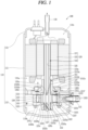
- FIG. 1 is a longitudinal sectional view showing a rotary compressor 100 of the present disclosure
- FIG. 2 is a perspective view showing a compression unit 130 of the rotary compressor 100 of the present disclosure
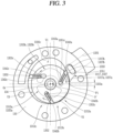
- FIG. 3 is a transverse sectional view showing the compression unit 130 of the rotary compressor 100 of the present disclosure
- FIG. 4 is an exploded perspective view showing the compression unit 130 of the rotary compressor 100 of the present disclosure.
- the rotary compressor 100 according to the present disclosure may be a vane rotary compressor 100.
- the rotary compressor 100 according to the present disclosure may reduce a surface pressure between suction ports 1331 in a vane-type compressor for vehicles and air conditioning to improve reliability and overcome mechanical loss.
- the rotary compressor 100 includes a cylinder 133, a roller 134, and a plurality of vanes 1351, 1352, 1353.
- the cylinder 133 is configured with an annular inner peripheral surface to define a compression space V.
- the cylinder 133 is provided with a suction flow path of refrigerant.
- the suction flow path includes a suction port 1331 and a suction passage 1333, and the suction port 1331 is disposed to communicate with the compression space V to suck refrigerant and provide it to the compression space V.
- the refrigerant sucked into the suction port 1331 may be a refrigerant gas, and may be separated into a refrigerant liquid and a refrigerant gas in an accumulator, and the separated refrigerant gas flows into the compression space V through the suction port 1331 of the cylinder 133, and the refrigerant liquid flows back into an evaporator.
- the suction passage 1333 is disposed in a direction crossing the suction port 1331, and is disposed to allow communication between the compression space V and the suction port 1331.
- the refrigerant flows into the compression space V through the suction port 1331 and the suction passage 1333.
- suction passage 1333 The detailed structure of the suction passage 1333 will be described later.
- An inner peripheral surface 1332 of the cylinder 133 may be defined in an elliptical shape, and an inner peripheral surface 1332 of the cylinder 133 according to the present embodiment may be combined such that a plurality of ellipses, for example, four ellipses having different major and minor ratios have two origins to define an asymmetric elliptical shape, and a detailed description of the shape of the inner peripheral surface of the cylinder 133 will be described later.
- the roller 134 is rotatably provided in the compression space V of the cylinder 133.
- the roller 134 is configured with a plurality of vane slots 1342a, 1342b, 1342c with a predetermined interval along the outer peripheral surface.
- the compression space V is defined between an inner periphery of the cylinder 133 and an outer periphery of the roller 134.
- the compression space V is a space defined between the inner peripheral surface of the cylinder 133 and the outer peripheral surface of the roller 134.
- the compression space V is divided into spaces as many as the number of vanes 1351, 1352, 1353 by the plurality of vanes 1351, 1352, 1353.
- FIG. 3 it is shown an example in which the compression space V is partitioned into a first compression space V1 provided at a side of discharge ports 1313a, 1313b, 1313c, a second compression space V2 provided at a side of the suction port 1331, and a third compression space V3 provided between the side of the suction port 1331 and the side of the discharge ports 1313a, 1313b, 1313c by the three vanes 1351, 1352, 1353.
- the vanes 1351, 1352, 1353 are slidably inserted into the vane slots 1342a, 1342b, 1342c, and are configured to rotate together with the roller 134.
- a back pressure is provided at a rear end of the vane 1351, 1352, 1353 to allow a front end surfaces 1351a, 1351b, 1351c of the vane 1351, 1352, 1353 to come into contact with the inner periphery of the cylinder 133.
- the vanes 1351, 1352, 1353 are provided in plurality to define a multi-back pressure structure, and the front end surfaces 1351a, 1351b, 1351c of the plurality of vanes 1351, 1352, 1353 come into contact with the inner periphery of the cylinder 133, thereby allowing the compression space V to be partitioned into the plurality of compressed spaces V1, V2, V3.
- FIG. 3 An example in which three vanes 1351, 1352, 1353 are provided in the present disclosure is shown in FIG. 3 and the like, thereby allowing the compression space V to be partitioned into the three compression spaces V1, V2, V3.
- high-pressure refrigerant may be accommodated between one of the plurality of vanes 1351, 1352, 1353 and the inner periphery of the cylinder 133, and a predetermined back pressure may be maintained such that the front end surfaces 1351a, 1351b, 1351c of the vanes 1351, 1352,1353 come into contact with the inner periphery of the cylinder 133 until the high-pressure refrigerant is bypassed to the suction port 1331.
- the predetermined back pressure may be understood as a discharge back pressure that enables the high-pressure refrigerant to be discharged into an inner space of a casing 110 through the discharge ports 1313a, 1313b, 1313c of the compression space V.
- a time point at which the high-pressure refrigerant is bypassed to the suction port 1331 may be understood as a "suction start time point", which is a time point at which suction starts.
- the rotary compressor 100 may further include a casing 110, a drive motor 120 provided inside the casing 110 to generate rotational power, and a main bearing 131 and a sub bearing 132 provided at both ends of the cylinder 133 and disposed to be spaced apart from each other, respectively, to define both surfaces of the compression space V, respectively.
- the drive motor 120 may be provided in an upper inner space 110a of the casing 110, and the compression unit 130 in a lower inner space 110b of the casing 110, respectively, and the drive motor 120 and the compression unit 130 may be connected by a rotating shaft 123.
- the casing 110 which is a portion constituting an exterior of the compressor, may be divided into a vertical or horizontal type depending on an aspect of installing the compressor.
- the vertical type has a structure in which the drive motor 120 and the compression unit 130 are disposed at both upper and lower sides along an axial direction
- the horizontal type has a structure in which the drive motor 120 and the compression unit 130 are disposed at both left and right sides.
- the casing 110 according to the present embodiment will be mainly described on the vertical type, but it is not excluded that the casing 110 is also applied to the horizontal type.
- the casing 110 may include an intermediate shell 111 defined in a cylindrical shape, a lower shell 112 covering a lower end of the intermediate shell 111, and an upper shell 113 covering an upper end of the intermediate shell 111.
- the drive motor 120 and the compression unit 130 may be inserted into and fixedly coupled to the intermediate shell 111, and a suction pipe 115 may be passed therethrough to be directly connected to the compression unit 130.
- the lower shell 112 is sealingly coupled to a lower end of the intermediate shell 111, and a storage oil space 110b in which oil to be supplied to the compression unit 130 is stored may be disposed below the compression unit 130.
- the upper shell 113 is sealingly coupled to an upper end of the intermediate shell 111, and an oil separation space 110c may be disposed above the drive motor 120 to separate oil from refrigerant discharged from the compression unit 130.
- the drive motor 120 which is a portion constituting the electric motor unit, provides power to drive the compression unit 130.
- the drive motor 120 includes a stator 121, a rotor 122, and the rotating shaft 123.
- the stator 121 may be fixedly provided inside the casing 110, and may be press-fitted and fixed to an inner peripheral surface of the casing 110 by a method such as shrink fitting.
- the stator 121 may be press-fitted and fixed to an inner peripheral surface of the intermediate shell 111.
- the rotor 122 is rotatably inserted into the stator 121, and the rotating shaft 123 is press-fitted and coupled to the center of the rotor 122. Accordingly, the rotating shaft 123 rotates concentrically together with the rotor 122.
- An oil flow path 125 is defined in a hollow hole shape at the center of the rotating shaft 123, and oil through holes 126a, 126b are disposed to pass therethrough toward an outer peripheral surface of the rotating shaft 123 in the middle of the oil flow path 125.
- the oil through holes 126a, 126b include a first oil through hole 126a belonging to a range of a main bush portion 1312 and a second oil through hole 126b belonging to a range of a second bearing portion 1322, which will be described later.
- Each of the first oil through hole 126a and the second oil through hole 126b may be configured by one or plurality.
- the present embodiment shows an example that is configured by a plurality of oil through holes.
- An oil pickup 127 may be provided in the middle or at a lower end of the oil flow path 125.
- the oil pickup 127 may include one of a gear pump, a viscous pump, and a centrifugal pump.
- the present embodiment shows an example to which a centrifugal pump is applied. Accordingly, when the rotating shaft 123 rotates, an oil filled in the oil storage space 110b of the casing 110 may be pumped by the oil pickup 127, and the oil may be sucked up along the oil flow path 125 and then supplied to a sub bearing surface 1322b of the sub bush portion 1322 through the second oil through hole 126b, and to a main bearing surface 1312b of the main bush portion 1312 through the first oil through hole 126a.
- the rotating shaft 123 may be integrally formed with the roller 134 or the roller 134 may be press-fitted and post-assembled thereto.
- the roller 134 it will be mainly described on an example in which the roller 134 is integrally formed with the rotating shaft 123, but the roller 134 will be described again later.
- a first bearing support surface (not shown) may be disposed at an upper half portion of the rotating shaft 123 with respect to the roller 134, that is, between a main shaft portion 123a press-fitted into the rotor 122 and a main bearing portion 123b extending toward the roller 134 from the main bearing portion 123b formed between the bearing parts 123b, and a second bearing support surface (not shown) may be disposed at a lower half portion of the rotating shaft 123 with respect to the roller 134, that is, on the rotating shaft 123 at a lower end of the sub bearing 132.
- the first bearing support surface constitutes a first axial support portion 151 together with a first shaft support surface (not shown) to be described later
- the second bearing support surface constitutes a second shaft support portion 152 together with a second shaft support surface (not shown) to be described later.
- the first bearing support surface and the second bearing support surface will be described later together with the first axial support portion 151 and the second axial support portion 152.
- the main bearing 131 and the sub bearing 132 may be respectively provided at both ends of the cylinder 133.
- the main bearing 131 and the sub bearing 132 are disposed to be spaced apart from each other to constitute both surfaces of the aforementioned compression space V, respectively.
- FIGS. 1 , 2 and 4 it is shown an example in which the main bearing 131 is provided at an upper end of the cylinder 133 to define an upper surface of the compression space V, and the sub bearing 132 is provided at a lower end of the cylinder 133 to define a lower surface of the compression space V.
- FIG. 5 is a longitudinal sectional view showing a compression unit of the rotary compressor 100 of the present disclosure
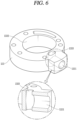
- FIG. 6 is a perspective view showing an example of the cylinder 133 of the rotary compressor 100 of the present disclosure.
- the suction passage 1333 may communicate between the compression space V and the suction port 1331, and is disposed in a direction crossing the suction port 1331.
- FIGS. 5 and 6 it is shown an example in which the suction passage 1333 is disposed to pass through upper and lower surfaces of the cylinder 133 in parallel with a vertical direction, and has an elliptical cross section.
- the suction passage 1333 may not be disposed in parallel with a vertical direction, but may be disposed to include first and second suction passages 1333a, 1333b in a direction intersecting the vertical direction, which will be described later.
- the suction passage 1333 is disposed in the vertical direction, instead of a structure in which refrigerant is directly sucked from a lateral direction, a suction flow path through which the refrigerant flows into the compression space V in upper and lower directions of the cylinder 133 is disposed.
- the terms “lateral direction”, “vertical direction”, “upward direction” and “downward direction” defines directions based on the rotary compressor of Fig. 1 installed in the manner that the axis of the rotating shaft 123 is aligned with “the vertical direction”.
- the "lateral direction” has the same meaning as “a horizontal direction” which is orthogonal to "the vertical direction”.
- the “upward direction” refers to a direction moving from a bottom end (adjacent to the sub bearing 132) of the rotating shaft 123 to a upper end (adjacent to the drive motor 120) of the rotating shaft, and the “downward direction” does vice versa.
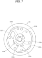
- FIG. 7 is a plan view showing a bottom surface of the main bearing 131 of the rotary compressor 100 of the present disclosure
- FIG. 8 is a plan view showing an upper surface of the main bearing 131 of the rotary compressor 100 of the present disclosure.
- a suction guide portion 1317, 1327 disposed on at least one of the main bearing 131 and the sub bearing 132 will be described.
- the suction guide portion 1317, 1327 may be disposed on at least one of the main bearing 131 and the sub bearing 132.
- the suction guide portion 1317, 1327 is concavely defined in the main bearing 131 or the sub bearing 132 to communicate between the suction passage 1333 and the compression space V so as to accommodate and guide refrigerant that has passed through the suction passage 1333 to be provided to the compression space V.
- FIGS. 1 , 2 and 4 it is shown an example in which the main bearing 131 is provided at upper end of the cylinder 133 to define an upper surface of the compression space V, and the sub bearing 132 is provided at a lower end of the cylinder 133 to define a lower surface of the compression space V.
- the suction guide portion 1317, 1327 may include a main suction guide portion 1317.
- the main suction guide portion 1317 may be concavely defined to communicate between the suction passage 1333 and the compression space V in the main bearing 131.
- main suction guide portion 1317 may accommodate and provide refrigerant that has passed through the suction passage 1333 to the compression space V to flow in an upward direction.
- main suction guide portion 1317 in a rhombus shape is shown, but the shape of the main suction guide portion 1317 may not be necessarily limited to this structure, and any structure may be employed as long as it is a structure capable of accommodating refrigerant that has passed through the suction passage 1333 and guiding its flow to provide the refrigerant to the compression space V.
- the main suction guide portion 1317 must communicate with the suction passage 1333 and the compression space V, respectively, and is preferably assembled so as not to communicate with the outside to constitute a sealing structure.
- main suction guide portion 1317 must have a structure capable of accommodating all or part of an upper end of the suction passage 1333.
- the main suction guide portion 1317 may include one side portion 1317a of the main suction guide portion 1317 extending toward a proximal point P1, and the other side portion 1317b disposed at an opposite side of the one side portion 1317a.
- FIG. 3 it is shown an example in which one side portion 1317a of the main suction guide portion 1317 is disposed to be longer than the other side portion 1317b. Accordingly, the main suction guide portion 1317 constitutes an asymmetric structure.
- One side portion 1317a of the main suction guide portion 1317 is disposed to be longer than the other side portion 1317b, and extends toward the proximal point P1 to further improve suction efficiency.
- a radius of curvature at the corner of 1317a may be longer than that at the corner of 1317b.
- the suction guide portions 1317, 1327 may further include a sub suction guide portion 1327.
- the sub suction guide portion 1327 may be concavely defined to communicate between the suction passage 1333 and the compression space V in the sub bearing 132.
- sub suction guide portion 1327 may accommodate refrigerant that has passed through the suction passage 1333 to flow in a downward direction so as to be provided to the compression space V.
- the shape of the sub suction guide portion 1327 may not be necessarily limited to this structure, and any structure may be employed as long as it is a structure capable of accommodating refrigerant that has passed through the suction passage 1333 and guiding its flow to provide the refrigerant to the compression space V.
- the sub suction guide portion 1327 similarly to the main suction guide portion 1317 described above, must communicate with the suction passage 1333 and the compression space V, respectively, and is preferably assembled so as not to communicate with the outside to constitute a sealing structure.
- the sub suction guide portion 1327 must have a structure capable of accommodating all or part of a lower end of the suction passage 1333.
- the sub suction guide portion 1327 may include one side portion 1327a of the sub suction guide portion 1327 disposed toward a proximal point P1, and the other side portion 1327b disposed at an opposite side of the one side portion 1327a.
- FIG. 3 it is shown an example in which one side portion 1327a of the sub suction guide portion 1327 is disposed to be longer than the other side portion 1327b. Accordingly, the sub suction guide portion 1327 constitutes an asymmetric structure.
- One side portion 1327a of the sub suction guide portion 1327 is disposed to be longer than the other side portion 1327b, and extends toward the proximal point P1 to further improve suction efficiency.
- a one side portion 1317a, 1327a and the other side portion 1317b, 1327b of the aforementioned suction guide portion 1317, 1327 are provided in at least one of the main suction guide portion 1317 and the sub suction guide portion 1327.
- both the main suction guide portion 1317 and the sub suction guide portion 1327 may include one side portion 1317a, 1327a and the other side portion 1317b, 1327b, and the main suction guide portion 1317 or the sub suction guide portion 1317 may include one side portion 1317a, 1327a and the other side portion 1317b, 1327b.
- FIGS. 7 and 8 it is shown an example in which the main suction guide portion 1317 and the sub suction guide portion 1327 are defined in shapes corresponding to each other.
- the suction flow path of refrigerant constitutes a flow path that communicates from the suction portion and the suction passage 1333 of the cylinder 133 to the main suction guide portion 1317 of the main bearing 131 and the sub suction guide portion 1327 of the sub bearing 132.
- FIG. 9 is a graph showing a comparison between efficiencies of the related art and the present disclosure, and as shown in FIG. 9 , there exists a point exceeding a critical surface pressure of the suction port 1331 between crank angles of 0 and 60 degrees due to an inflow of refrigerant gas through the lateral suction port 1331 in the case of the rotary compressor 100 in the related art, but the critical surface pressure of the suction port 1331 is not exceeded due to a decrease in surface pressure at the suction port 1331 between 0 and 60 degrees in the rotary compressor 100 of the present disclosure.
- the suction passage 1333 may be disposed to pass through upper and lower surfaces of the cylinder 133 in parallel with a vertical direction.
- FIGS. 5 and 6 it is shown an example in which the suction passage 1333 is disposed to pass through the upper and lower surfaces of the cylinder 133, and in FIG. 6 , it is also shown an example in which the suction passage 1333 has an elliptical cross section.
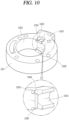
- FIG. 10 is a perspective view showing another example of the cylinder 133 of the rotary compressor 100 of the present disclosure
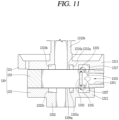
- FIG. 11 is a longitudinal sectional view showing the cylinder 133 of FIG. 10 .
- An inlet guide portion 1335 may be disposed on the upper and lower surfaces of the cylinder 133.
- the inlet guide portion 1335 may allow refrigerant flowing in the suction passage 1333 to flow into the compression space V, and referring to FIGS. 10 and 11 , the inlet guide portion 1335 has a predetermined width and depth, and may be disposed to communicate between the compression space V and the suction passage 1333.
- the inlet guide portion 1335 may be defined in a shape in which an inner periphery of the cylinder 133 adjacent to the suction passage 1333 and a portion of upper and lower surfaces of the cylinder 133 are cut off.
- the inlet guide portion 1335 may be formed by a chamfering process having a predetermined width and depth.
- the inflow of refrigerant into the compression space V through the suction passage 1333 may be efficiently carried out by the inlet guide portion 1335 to reduce the suction loss of the refrigerant.
- refrigerant may more efficiently flow into the compression space through the inlet guide portion 1335.
- a suction area sucked from the suction passage 1333 into the compression space V may be increased by the inlet guide portion 1335, thereby further reducing surface pressure.
- a depth of the inlet guide portion 1335 is preferably defined to a suitable depth so as to be equal to or lower than that of the suction guide portion 1317, 1327.
- the inlet guide portion 1335 may be disposed to have a suitable depth, thereby preventing a problem in which a contact area with the vanes 1351, 1352, 1353 decreases and a problem in which a surface pressure thereto increases.
- FIG. 12 is a graph showing an efficiency of a surface pressure in the present disclosure, and referring to FIG. 12 , there exists a point exceeding a critical surface pressure of the suction port 1331 between crank angles of 0 and 60 degrees due to an inflow of refrigerant gas through the lateral suction port 1331 in the case of the rotary compressor 100 in the related art, but the critical surface pressure of the suction port 1331 is not exceeded due to a decrease in surface pressure at the suction port 1331 between 0 and 60 degrees in the rotary compressor 100 of the present disclosure.
- FIG. 13 is a perspective view showing still another example of the cylinder 133 of the rotary compressor 100 of the present disclosure
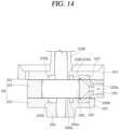
- FIG. 14 is a longitudinal sectional view showing the cylinder 133 of FIG. 13 .
- the suction passage 1333a, 1333b may include the first and second suction passages 1333a, 1333b.
- the first suction passage 1333a may be disposed to communicate with the suction port 1331 in a direction crossing a vertical direction, and pass through an upper surface of the cylinder 133. Furthermore, the first suction passage 1333a may communicate with the main suction guide portion 1317. In other words, the first suction passage 1333a may extend at a slanted angle with respect to the vertical direction.
- the second suction passage 1333b may be disposed in a direction crossing the first suction passage 1333a to communicate therewith, and pass through a lower surface of the cylinder 133. Furthermore, the second suction passage 1333b may communicate with the sub suction guide portion 1327. In other words, the second suction passage 1333b may extend at another slanted angle with respect to the vertical direction.
- refrigerant sucked through the suction port 1331 may pass through the first and second suction passages 1333a, 1333b, and the refrigerant that has passed through the first and second suction passages 1333a, 1333b, respectively, may be guided through the main suction guide portion 1317 and the sub suction guide portion 1327, respectively, to flow into the compression space V, thereby reducing a loss of the suction flow path, and constituting an advantageous structure capable of improving a suction efficiency of the rotary compressor 100.
- the suction passage 1333 includes the first and second suction passages 1333a, 1333b. Furthermore, it is shown an example in which the first and second suction passages 1333a, 1333b are defined with a Y-shaped cross section lying down in FIG. 14 along with the suction port 1331 communicating therewith.
- FIG. 14 it is shown an example in which the first and second suction passages 1333a, 1333b are respectively disposed in upper-left and lower-left directions from a left side end of the suction port 1331, and may be respectively disposed in a diagonal direction of about 45 degrees.
- first suction passage 1333a communicates with the main suction guide portion 1317
- second suction passage 1333b communicates with the sub suction guide portion 1327
- refrigerant sucked through the suction port 1331 may pass through the first and second suction passages 1333a, 1333b
- the refrigerant that has passed through the first and second suction passages 1333a, 1333b, respectively may be guided through the main suction guide portion 1317 and the sub suction guide portion 1327, respectively, to flow into the compression space V, thereby reducing a loss of the suction flow path, and constituting an advantageous structure capable of improving a suction efficiency of the rotary compressor 100.
- At least one of the main bearing 131 and the sub bearing 132 may be provided with at least one of back pressure pockets 1315a, 1315b, 1325a, 1325b concavely disposed to communicate with the compression space V.
- the back pressure chamber 1343a, 1343b, 1343c may be disposed at an inner end of the vane slot 1342a, 1342b, 1342c, and the back pressure chamber 1343a, 1343b, 1343c receives a back pressure from the back pressure pocket 1315a, 1315b, 1325a, 1325b while communicating with the back pressure pocket 1315a, 1315b, 1325a, 1325b to pressurize the vane 1351, 1352, 1353 toward the inner periphery of the cylinder 133.
- the back pressure chamber 1343a, 1343b, 1343c is provided at the inner end of the vane slot 1342a, 1342b, 1342c, and may be understood as a space defined between the rear end of the vane 1351, 1352, 1353 and the inner end of the vane slot 1342a, 1342b, 1342c.
- the back pressure chambers 1343a, 1343b, 1343c may be communicable with first and second main back pressure pockets 1315a, 1315b and first and second sub back pressure pockets 1325a, 1325b, which will be described later, to receive back pressures from the first and second main back pressure pockets 1315a, 1315b and the first and second sub back pressure pockets 1325a, 1325b in such a manner that front end surfaces 1351a, 1351b, 1351c of the vanes 1351, 1352, 1353 may be disposed to be in contact with the inner periphery of the cylinder 133 or to be spaced apart from the inner periphery of the cylinder 133 by a predetermined distance.
- At least part of the back pressure chamber 1343a, 1343b, 1343c may be defined as an arc surface, and a diameter of the arc surface of the back pressure chamber 1343a, 1343b, 1343c may be smaller than a distance between the first and second main back pressure pockets 1315a, 1315b. Due to this, when communicating with the first main back pressure pocket 1315a at high pressure by a discharge back pressure to receive the discharge back pressure while at the same time communicating with the second main back pressure pocket 1315b, an intermediate pressure of the second main back pressure pocket 1315b may be received as well to prevent a back pressure at rear ends of the vanes 1351, 1352, 1353 from being excessively increased.
- FIG. 3 it is shown an example in which the back pressure chamber 1343a, 1343b, 1343c is connected to the vane slot 1342a, 1342b, 1342c while having an arc surface, and a diameter of the arc surface of the back pressure chamber 1343a, 1343b, 1343c is made smaller than a distance between the first and second main back pressure pockets 1315a, 1315b.
- the vane 1351, 1352, 1353 when a high back pressure is received from the first main back pressure pocket 1315a and the first sub back pressure pocket 1325a, the vane 1351, 1352, 1353 may be maximally drawn out such that a front end surface 1351a, 1351b, 1351c of the vane 1351, 1352, 1353 comes into contact with an inner periphery of the cylinder 133, and when an intermediate back pressure is received from the second main back pressure pocket 1315b and the second sub back pressure pocket 1325b, the vane 1351, 1352, 1353 may be drawn out in relatively small amount such that the front end surface 1351a, 1351b, 1351c of the vane 1351, 1352, 1353 is spaced apart from the inner periphery of the cylinder 133 by a predetermined distance.
- the back pressure pocket 1315a, 1315b, 1325a, 1325b is in communication with the back pressure chamber 1343a, 1343b, 1343c to allow the front end surface 1351a, 1351b, 1351c of the vane 1351, 1352, 1353 to come into contact with an inner periphery of the cylinder 133, and thus a predetermined back pressure within the back pressure pocket 1315a, 1315b, 1325a, 1325b pressurizes a rear end of the vane 1351, 1352, 1353 through the back pressure chamber 1343a, 1343b, 1343c, and the front end surface 1351a,
- one or more back pressure pockets 1315a, 1315b, 1325a, 1325b may be disposed in each of the main bearing 131 and the sub bearing 132, and in the present disclosure, an example in which two back pressure pockets are defined in each of the main bearing 131 and the sub bearing 132 will be described.
- the present disclosure is not necessarily limited to this structure, and the back pressure pockets 1315a, 1315b, 1325a, 1325b may be provided only in the main bearing 131, and furthermore, may have an example in which one or three of the back pressure pockets 1315a, 1315b, 1325a, 1325b is or are defined in each of the main bearing 131 and the sub bearing 132.
- the main bearing 131 may include a main plate 1311 coupled to the cylinder 133 to cover an upper side of the cylinder 133.
- the sub bearing 132 may include a sub plate 1321 coupled to the cylinder 133 to cover a lower side of the cylinder 133.
- the back pressure pockets 1315a, 1315b, 1325a, 1325b may include first and second main back pressure pockets 1315a, 1315b spaced apart from each other at a predetermined distance from a lower surface of the main plate 1311 of the main bearing 131.
- the back pressure pockets 1315a, 1315b, 1325a, 1325b may further include first and second sub back pressure pockets 1325a, 1325b spaced apart from each other at a predetermined distance from an upper surface of the sub bearing 132.
- first and second main back pressure pockets 1315a, 1315b and the first and second sub back pressure pockets 1325a, 1325b will be described later.
- the compression unit 130 is configured to include the cylinder 133, the roller 134, the plurality of vanes 1351, 1352, 1353, the main bearing 131, and the sub bearing 132.
- the main bearing 131 and the sub bearing 132 are provided at both upper and lower sides of the cylinder 133, respectively, to constitute the compression space V together with the cylinder 133, the roller 134 is rotatably provided in the compression space V, the vanes 1351, 1352, 1353 are slidably inserted into the roller 134, the plurality of vanes 1351, 1352, 1353 respectively come into contact with the inner periphery of the cylinder 133, and the compression space V is partitioned into a plurality of compression chambers.
- the main bearing 131 may be fixedly provided at the intermediate shell 111 of the casing 110.
- the main bearing 131 may be inserted into and welded to the intermediate shell 111.
- the main bearing 131 may be closely coupled to an upper end of the cylinder 133. Accordingly, the main bearing 131 defines an upper surface of the compression space V, and supports an upper surface of the roller 134 in an axial direction, and at the same time supports an upper half portion of the rotating shaft 123 in a radial direction.
- the main bearing 131 may include a main plate portion 1311 and a main bush portion 1312.
- the main plate portion 1311 may be coupled to the cylinder 133 to cover an upper side of the cylinder 133.
- the main bush portion 1312 extends from the center of the main plate portion 1311 in an axial direction toward the drive motor 120 to support the upper half portion of the rotating shaft 123.
- the main plate portion 1311 may be defined in a disk shape, and an outer peripheral surface of the main plate portion 1311 may be closely fixed to an inner peripheral surface of the intermediate shell 111.
- At least one discharge port 1313a, 1313b, 1313c may be disposed in the main plate portion 1311, a plurality of discharge valves 1361, 1362, 1363 may be provided at an upper surface of the main plate portion 1311 to open and close each discharge port 1313a, 1313b, 1313c, and a discharge muffler 137 having a discharge space (no reference numeral) may be provided at an upper side of the main plat portion 1311 to accommodate the discharge ports 1313a, 1313b, 1313c and the discharge valves 1361, 1362, 1363.
- the discharge ports 1313a, 1313b, 1313c will be described later.
- a first main back pressure pocket 1315a and a second main back pressure pocket 1315b may be disposed on a lower surface of the main plate portion 1311 facing an upper surface of the roller 134 between both axial side surfaces of the main plate portion 1311.
- the first main back pressure pocket 1315a and the second main back pressure pocket 1315b may be defined in an arc shape and disposed at a predetermined interval along a circumferential direction. Inner peripheral surfaces of the first main back pressure pocket 1315a and the second main back pressure pocket 1315b may be defined in a circular shape, but outer peripheral surfaces thereof may be defined in an elliptical shape in consideration of the vane slots 1342a, 1342b, 1342c to be described later.
- first main back pressure pocket 1315a may accommodate high-pressure refrigerant to provide a high back pressure to a rear end of the vane 1351, 1352, 1353
- second main back pressure pocket 1315b may accommodate intermediate-pressure refrigerant to provide an intermediate back pressure to the rear end of the vane 1351, 1352, 1353.
- the first main back pressure pocket 1315a and the second main back pressure pocket 1315b may be defined within an outer diameter range of the roller 134. Accordingly, the first main back pressure pocket 1315a and the second main back pressure pocket 1315b may be separated from the compression space V.
- a back pressure in the first main back pressure pocket 1315a may be greater than that in the second main back pressure pocket 1315b. That is, the first main back pressure pocket 1315a may be provided in the vicinity of the discharge ports 1313a, 1313b, 1313c to provide a discharge back pressure. Furthermore, the second main back pressure pocket 1315b may define an intermediate pressure between the suction pressure and the discharge pressure.
- oil refrigerant oil
- first main bearing protrusion 1316a may pass through a fine passage between a first main bearing protrusion 1316a and an upper surface 134a of the roller 134, which will be described later, to flow into the first main back pressure pocket 1315a.
- the second main back pressure pocket 1315b may be defined within a range of the compression chamber defining an intermediate pressure in the compression space V. Accordingly, the second main back pressure pocket 1315b maintains an intermediate pressure.
- the second main back pressure pocket 1315b may define an intermediate pressure that is a pressure lower than that of the first main back pressure pocket 1315a.
- oil flowing into the main bearing hole 1312a of the main bearing 131 through the first oil through hole 126a may flow into the second main back pressure pocket 1315b.
- the second main back pressure pocket 1315b may be defined within a range of the compression chamber V2 defining a suction pressure in the compression space V. Accordingly, the second main back pressure pocket 1315b maintains the suction pressure.
- the first main bearing protrusion 1316a and the second main bearing protrusion 1316b may be disposed to extend from the main bearing surface 1312b of the main bush portion 1312. Accordingly, the first main back pressure pocket 1315a and the second main back pressure pocket 1315b may be sealed to the outside, and at the same time, the rotating shaft 123 may be stably supported.
- the first main bearing protrusion 1316a and the second main bearing protrusion 1316b may be disposed at the same height, and an oil communication groove (not shown) or an oil communication hole (not shown) may be disposed on an inner peripheral end surface of the second main bearing protrusion 1316b.
- an inner peripheral height of the second main bearing protrusion 1316b may be disposed to be lower than that of the first main bearing protrusion 1316a. Accordingly, high-pressure oil (refrigerant oil) flowing into the main bearing surface 1312b may flow into the first main back pressure pocket 1315a.
- the first main back pressure pocket 1315a defines a higher pressure (discharge pressure) than the second main back pressure pocket 1315b.
- the main bush portion 1312 may be disposed in a hollow bush shape, and a first oil groove 1312c may be disposed on an inner peripheral surface of the main bearing hole 1312a constituting an inner peripheral surface of the main bush portion 1312.
- the first oil groove 1312c may be defined in an oblique or spiral shape between upper and lower ends of the main bush portion 1312 such that the lower end thereof communicates with the first oil through hole 126a.
- FIG. 4 it is shown an example in which the main bush portion 1312 is defined in an upward direction in a hollow bush shape on the main plate 1311, and the oil groove 1312c is defined in an oblique direction on an inner peripheral surface of the main bearing hole 1312a constituting an inner peripheral surface of the main bush portion 1312.
- an oil groove may be defined in a diagonal or spiral shape on an outer peripheral surface of the rotating shaft 123, that is, an outer peripheral surface of the main bearing portion 123b.
- the sub bearing 132 may be closely coupled to a lower end of the cylinder 133. Accordingly, the sub bearing 132 defines a lower surface of the compression space V, and supports a lower surface of the roller 134 in an axial direction, and at the same time supports a lower half portion of the rotating shaft 123 in a radial direction.
- the sub bearing 132 may include a sub plate portion 1321 and a sub bush portion 1322.
- the sub plate portion 1321 may be coupled to the cylinder 133 to cover a lower side of the cylinder 133.
- the sub bush portion 1322 extends from the center of the sub plate portion 1321 in an axial direction toward the lower shell 112 to support the lower half portion of the rotating shaft 123.
- the sub plate portion 1321 may be defined in a disk shape similar to that of the main plate portion 1311, and an outer peripheral surface of the sub plate portion 1321 may be spaced apart from an inner peripheral surface of the intermediate shell 111.
- a first sub back pressure pocket 1325a and a second sub back pressure pocket 1325b may be disposed on an upper surface of the sub plate portion 1321 facing a lower surface of the roller 134 between both axial side surfaces of the sub plate portion 1321.
- the first sub back pressure pocket 1325a and the second sub back pressure pocket 1325b may be disposed to be symmetrical with respect to the first main back pressure pocket 1315a and the second main back pressure pocket 1315b, respectively, described above around the roller 134.
- first and second sub back pressure pockets 1325a, 1325b may be defined in a shape corresponding to the first and second main back pressure pockets 1315a, 1315b, respectively.
- first sub back pressure pocket 1325a may be disposed to be symmetrical with respect to the first main back pressure pocket 1315a with the roller 134 interposed therebetween, and the second sub back pressure pocket 1325b to be symmetrical with respect to the second main back pressure pocket 1315b with the roller 134 interposed therebetween.
- a first sub bearing protrusion 1326a may be disposed on an inner peripheral side of the first sub back pressure pocket 1325a
- a second sub bearing protrusion 1326b may be disposed on an inner peripheral side of the second sub back pressure pocket 1325b, respectively.
- first sub back pressure pocket 1325a and the second sub back pressure pocket 1325b may be disposed to be asymmetrical with respect to the first main back pressure pocket 1315a and the second main back pressure pocket 1315b, respectively, around the roller 134.
- first sub back pressure pocket 1325a and the second sub back pressure pocket 1325b may be disposed to have different depths from those of the first main back pressure pocket 1315a and the second main back pressure pocket 1315b.
- an oil supply hole (not shown) may be disposed between the first sub back pressure pocket 1325a and the second sub back pressure pocket 1325b, precisely, between the first sub bearing protrusion 1326a and the second sub bearing protrusion 1326b or at a portion where the first sub bearing protrusion 1326a and the second sub bearing protrusion 1326b are connected to each other.
- a first end constituting an inlet of the oil supply hole may be disposed to be submerged in the oil storage space 110b, and a second end constituting an outlet of the oil supply hole may be disposed to be positioned on a rotation path of the back pressure chambers 1343a, 1343b, 1343c on an upper surface of the sub plate portion 1321 facing a lower surface of the roller 134 to be described later.
- high-pressure oil stored in the oil storage space 110b may be periodically supplied to the back pressure chambers 1343a, 1343b, 1343c through the oil supply hole (not shown) while the back pressure chambers 1343a, 1343b, 1343c periodically communicate with the oil supply hole (not shown), and through this, each of the vanes 1351, 1352, 1353 may be stably supported toward the inner peripheral surface 1332 of the cylinder 133.
- the sub bush portion 1322 may be disposed in a hollow bush shape, and a second oil groove 1322c may be disposed on an inner peripheral surface of the sub bearing hole 1322a constituting an inner peripheral surface of the sub bush portion 1322.
- the second oil groove 1322c may be defined in a straight line or an oblique line between upper and lower ends of the sub bush portion 1322 such that the upper end thereof communicates with the second oil through hole 126b of the rotating shaft 123.
- an oil groove may be defined in a diagonal or spiral shape on an outer peripheral surface of the rotating shaft 123, that is, an outer peripheral surface of a sub bearing portion 123c.
- back pressure pockets 1315a, 1315b, 1325a, 1325b may be disposed in only one of the main bearing 131 and the sub bearing 132.
- discharge ports 1313a, 1313b, 1313c may be disposed in the main bearing 131 as described above.
- the discharge ports 1313a, 1313b, 1313c may be disposed in the sub bearing 132 or may be disposed in the main bearing 131 and the sub bearing 132, respectively, and disposed to pass through between inner and outer peripheral surfaces of the cylinder 133.
- the present embodiment will be mainly described on an example in which the discharge ports 1313a, 1313b, 1313c are disposed in the main bearing 131.
- the plurality of the discharge ports 1313a, 1313b, 1313c may be disposed at a predetermined interval along a compression advancing direction (or a rotational direction of the roller 134, a clockwise direction indicated by an arrow on the roller 134 in FIG. 3 ).
- FIGS. 3 and 7 it is shown an example in which a total of six discharge ports 1313a, 1313b, 1313c in pairs are disposed to pass through the main bearing 131.
- the discharge port 1313a, 1313b, 1313c may be divided into a plurality of discharge ports 1313a, 1313b, 1313c to be defined along a rotational direction (or compression advancing direction) of the roller 134.
- the plurality of discharge ports 1313a, 1313b, 1313c may be respectively defined one by one, but may be defined in pairs as in the present embodiment.
- FIG. 3 it is shown an example in which the discharge ports 1313a, 1313b, 1313c according to the present embodiment are arranged in the order of the first discharge port 1313a, the second discharge port 1313b, and the third discharge port 1313c from the discharge ports 1313a, 1313b, 1313c disposed relatively far from a proximal portion 1332a.
- the plurality of discharge ports 1313a, 1313b, 1313c may communicate with one compression chamber.
- a first gap between the first discharge port 1313a and the second discharge port 1313b, a second gap between the second discharge port 1313b and the third discharge port 1313c, and a third gap between the third discharge port 1313c and the first discharge port 1313a may be defined to be the same as one another.
- the first gap, the second gap and the third gap may be defined to be substantially the same as a circumferential length of the first compression chamber V1, a circumferential length of the second compression chamber V2, and a circumferential length of the third compression chamber V3, respectively.
- the plurality of discharge ports 1313a, 1313b, 1313c may communicate with one compression chamber, and the plurality of compression chambers do not communicate with one discharge port 1313a, 1313b, 1313c, but the first discharge port 1313a may communicate with the first compression chamber V1, the second discharge port 1313b with the second compression chamber V2, and the third discharge port 1313c with the third compression chamber V3, respectively.
- each compression chamber V1, V2, V3 may be defined to be different, and a plurality of compression ports 1313a, 1313b, 1313c may communicate with one compression chamber or a plurality of compression chambers may communicate with one discharge port 1313a, 1313b, 1313c.
- a discharge groove (not shown) may be disposed to extend to the discharge port 1313a, 1313b, 1313c according to the present exemplary embodiment.
- the discharge groove may extend in an arc shape along a compression advancing direction (rotational direction of the roller 134). Accordingly, refrigerant that is not discharged from a preceding compression chamber may be guided to the discharge port 1313a, 1313b, 1313c communicating with a subsequent compression chamber through the discharge groove to be discharged together with the refrigerant compressed in the subsequent compression chamber. Through this, residual refrigerant in the compression space V may be minimized to suppress over-compression, thereby improving compressor efficiency.
- the discharge groove as described above may be disposed to extend from the final discharge port 1313a, 1313b, 1313c (e.g., the third discharge port 1313c).
- the compression space V may be partitioned into a suction chamber and a discharge chamber at both sides with the proximal portion (proximal point) 1332a interposed therebetween, the discharge port 1313a, 1313b, 1313c is unable to overlap the proximal point P1 positioned in the proximal portion 1332a in consideration of sealing between the suction chamber and discharge chamber.
- a residual space spaced apart between the inner peripheral surface 1332 of the cylinder 133 and the outer peripheral surface 1341 of the roller 134 is defined along a circumferential direction, refrigerant remains in this residual space without being discharged through the final discharge port 1313a, 1313b, 1313.
- the residual refrigerant may increase a pressure of the final compression chamber to cause a decrease in compression efficiency due to over-compression.
- a residual discharge hole may be disposed in a residual space in addition to the discharge groove.
- the residual discharge hole may be disposed to have a smaller inner diameter compared to the discharge port 1313a, 1313b, 1313c, and unlike the discharge port 1313a, 1313b, 1313c, the residual discharge hole may be always open without being opened or closed by the discharge valve.
- the plurality of discharge ports 1313a, 1313b, 1313c may be opened and closed by respective discharge valves 1361, 1362, 1363 described above.
- Each of the discharge valves 1361, 1362, 1363 may be configured with a cantilevered reed valve having one end constituting a fixed end and the other end constituting a free end. Since each of these discharge valves 1361, 1362, 1363 is widely known in the rotary compressor 100 in the related art, a detailed description thereof will be omitted.
- the cylinder 133 may be in close contact with a lower surface of the main bearing 131 and bolt-fastened to the main bearing 131 together with the sub bearing 132. As described above, since the main bearing 131 is fixedly coupled to the casing 110, the cylinder 133 may be fixedly coupled to the casing 110 by the main bearing 131.
- the cylinder 133 may be defined in an annular shape having an empty space portion to form the compression space V in the center.
- the empty space portion may be sealed by the main bearing 131 and the sub bearing 132 to form the above-described compression space V, and the roller 134 may be rotatably coupled to the compression space V.
- the cylinder 133 may be defined such that the suction port 1331 passes through inner and outer peripheral surfaces thereof.
- the suction port 1331 may be disposed to pass through inner and outer peripheral surfaces of the main bearing 131 or the sub bearing 132.
- the suction port 1331 may be disposed at one side in a circumferential direction around the proximal point P1 to be described later.
- the discharge ports 1313a, 1313b, 1313c described above may be disposed in the main bearing 131 at the other side in a circumferential direction opposite to the suction port 1331 around the proximal point P1.
- the inner peripheral surface 1332 of the cylinder 133 may be defined in an elliptical shape.
- the inner peripheral surface 1332 of the cylinder 133 according to the present embodiment may be defined in an asymmetric elliptical shape by combining a plurality of ellipses, for example, four ellipses having different major and minor ratios to have two origins.
- the inner peripheral surface 1332 of the cylinder 133 may be defined to have a first origin Or, which is the rotation center of the roller 134 (an axial center or an outer diameter center of the cylinder 133), and a second origin O' that is biased toward a distal portion 1332b with respect to the first origin Or.
- the X-Y plane defined around the first origin Or defines third and fourth quadrants
- the X-Y plane defined around the second origin O' defines first and second quadrants.
- the third quadrant may be defined by the third ellipse
- the fourth quadrant by the fourth ellipse respectively
- the first quadrant may be defined by the first ellipse
- the second quadrant by the second ellipse, respectively.
- the inner peripheral surface 1332 of the cylinder 133 may include a proximal portion 1332a, a distal portion 1332b, and a curved portion 1332c.
- the proximal portion 1332a is a portion closest to an outer peripheral surface of the roller 134 (or the rotation center Or of the roller 134)
- the distal portion 1332b is a portion farthest from the outer peripheral surface 1341 of the roller 134
- the curved portion 1332c is a portion connecting the proximal portion 1332a and the distal portion 1332b.
- the roller 134 may be rotatably provided in the compression space V of the cylinder 133, and the plurality of vanes 1351, 1352, 1353 may be inserted at a predetermined interval into the roller 134 along a circumferential direction. Accordingly, compression chambers as many as the number of the plurality of vanes 1351, 1352, 1353 may be partitioned and defined in the compression space V. In the present embodiment, it will be mainly described an example in which the plurality of vanes 1351, 1352, 1353 are made up of three and the compression space V are partitioned into three compression chambers.
- the roller 134 has an outer peripheral surface 1341 defined in a circular shape, and the rotating shaft 123 may be extended as a single body or may be post-assembled and combined therewith at the rotation center Or of the roller 134. Accordingly, the rotation center Or of the roller 134 is coaxially positioned with respect to an axial center (unsigned) of the rotating shaft 123, and the roller 134 rotates concentrically together with the rotating shaft 123.
- the rotation center Or of the roller 134 may be eccentrically disposed with respect to an outer diameter center Oc of the cylinder 133. Accordingly, in the roller 134, one side of the outer peripheral surface 1341 is almost in contact with the inner peripheral surface 1332 of the cylinder 133, precisely, the proximal portion 1332a to define the proximal point P1.
- the proximal point P1 may be defined in the proximal portion 1332a as described above. Accordingly, an imaginary line passing through the proximal point P1 may correspond to a major axis of an elliptical curve defining the inner peripheral surface 1332 of the cylinder 133.
- the roller 134 may have a plurality of vane slots 1342a, 1342b, 1342c disposed to be spaced apart from one another along a circumferential direction on the outer peripheral surface 1341 thereof, and the plurality of vanes 1351, 1352, 1353 to be described later may be slidably inserted into and coupled to the vane slots 1342a, 1342b, 1342c, respectively.
- a first vane slot 1342a, a second vane slot 1342b, and a third vane slot 1342c are shown along a compression advancing direction (a rotational direction of the roller 134, indicated by a clockwise arrow on the roller 134 in FIG. 3 ).
- the first vane slot 1342a, the second vane slot 1342b, and the third vane slot 1342c may be defined to have the same width and depth as one another at equal or unequal intervals along a circumferential direction, and there is shown an example in which they are disposed to be spaced apart at equal intervals in the present disclosure.
- the plurality of vane slots 1342a, 1342b, 1342c may be respectively disposed to be inclined by a predetermined angle with respect to a radial direction so as to sufficiently secure the lengths of the vanes 1351, 1352, 1353. Accordingly, when the inner peripheral surface 1332 of the cylinder 133 is defined in an asymmetric elliptical shape, even though a distance from the outer peripheral surface 1341 of the roller 134 to the inner peripheral surface 1332 of the cylinder 133 increases, the vanes 1351, 1352, 1353 may be suppressed from being released from the vane slots 1342a, 1342b, 1342c, thereby increasing a degree of freedom in designing the inner peripheral surface 1332 of the cylinder 133.
- Allowing a direction in which the vane slot 1342a, 1342b, 1342c is inclined to be an opposite direction to a rotational direction of the roller 134, that is, allowing the front end surface 1351, 1351b, 1351c of each vane 1351, 1352, 1353 in contact with the inner peripheral surface 1332 of the cylinder 133 to be inclined toward a rotational direction of the roller 134 may be preferable because compression start angle can be pulled toward the rotational direction of the roller 134 to quickly start compression.
- back pressure chambers 1343a, 1343b, 1343c may be disposed to communicate with one another at inner ends of the vane slots 1342a, 1342b, 1342c.
- the back pressure chamber 1343a, 1343b, 1343c is a space in which refrigerant (oil) at a discharge pressure or intermediate pressure is accommodated toward a rear side of each vane 1351, 1352, 1353, that is, the rear end portion 1351c, 1352c, 1353c of the vane 1351, 1352, 1353, and the each vane 1351, 1352, 1353 may be pressurized toward an inner peripheral surface of the cylinder 133 by a pressure of the refrigerant (or oil) filled in the back pressure chamber 1343a, 1343b, 1343c.
- a direction toward the cylinder 133 with respect to a movement direction of the vane 1351, 1352, 1353 is defined as a front side, and an opposite side thereto as a rear side.
- the back pressure chamber 1343a, 1343b, 1343c may be disposed to be sealed by the main bearing 131 and the sub bearing 132 at upper and lower ends thereof, respectively.
- the back pressure chambers 1343a, 1343b, 1343c may communicate independently with respect to each of the back pressure pockets 1315a, 1315b, 1325a, 1325, and may be disposed to communicate with one another by the back pressure pockets 1315a, 1315b, 1325a, 1325b.
- At least part of the back pressure chambers 1343a, 1343b, 1343c may be defined as an arc surface, and a diameter of the arc surface of the back pressure chambers 1343a, 1343b, 1343c may be smaller than a distance between the first and second main back pressure pockets 1315a, 1315b. Due to this, when communicating with the first main back pressure pocket 1315a at high pressure by a discharge back pressure to receive the discharge back pressure while at the same time communicating with the second main back pressure pocket 1315b, an intermediate pressure of the second main back pressure pocket 1315b may be received as well to prevent a back pressure at rear ends of the vanes 1351, 1352, 1353 from being excessively increased.
- FIG. 3 it is shown an example in which the back pressure chamber 1343a, 1343b, 1343c is connected to the vane slot 1342a, 1342b, 1342c while having an arc surface, and a diameter of the arc surface of the back pressure chamber 1343a, 1343b, 1343c is made smaller than a distance between the first and second main back pressure pockets 1315a, 1315b.
- the plurality of vanes 1351, 1352, 1353 may be slidably inserted into the vane slots 1342a, 1342b, 1342c, respectively. Accordingly, the plurality of vanes 1351, 1352, 1353 may be defined to have substantially the same shape as the vane slots 1342a, 1342b, 1342c, respectively.
- the plurality of vanes 1351, 1352, 1353 may be defined as a first vane 1351, a second vane 1352, and a third vane 1353 along a rotational direction of the roller 134, and the first vane 1351 may be inserted into the first vane slot 1342a, the second vane 1352 into the second vane slot 1342b, and the third vane 1353 into the third vane slot 1342c, respectively, and such a configuration is shown in FIGS. 3 and 4 .
- the plurality of vanes 1351, 1352, and 1353 may all have the same shape.
- each of the plurality of vanes 1351, 1352, 1353 may be defined as a substantially rectangular parallelepiped, the front end surface 1351a, 1351b, 1351c in contact with the inner peripheral surface 1332 of the cylinder 133 may be defined as a curved surface, and the rear end surface 1351b, 1352b, 1353b facing the respective back pressure chamber 1343a, 1343b, 1343c may be defined as a straight surface.
- FIG. 3 shows an example in which the front end surface 1351a of the first vane 1351 starts to come into contact with the cylinder 133 at a side of the suction port 1331, wherein chattering does not occur due to a high-pressure back pressure being provided at an rear end of the first vane 1351, the first vane 1351 comes into contact with the inner periphery of the cylinder 133, and high-pressure refrigerant between the front end surfaces 1351a, 1351b, 1351c of the first vane 1351 and the inner circumference of the cylinder 133 is bypassed to the suction port 1331 while the front end surface 1351a of the first vane 1351 passes the suction port 1331.
- the front end surface 1351a of the first vane 1351 comes into contact with the inner periphery of the cylinder 133 while not being pushed back by a high pressure back pressure in the back pressure pockets 1315a, 1315b, 1325a, 1325b communicating with the first main back pressure pocket 1315a and the first sub back pressure pocket 1325a.
- At least one back pressure pocket 1315a, 1315b, 1325a, 1325b, which is concavely disposed to communicate with the compression space V, is provided in at least one of the main bearing 131 and the sub bearing 132, the back pressure chamber 1343a, 1343b, 1343c in which a rear end of the vane 1351, 1352, 1353 is accommodated to receive a back pressure from the back pressure pocket 1315a, 1315b, 1325a, 1325b while communicating with the back pressure pocket 1315a, 1315b, 1325a, 1325b so as to pressurize the vane 1351, 1352, 1353 toward the inner periphery of the cylinder 133 is disposed at an inner end of the vane slot 1342a, 1342b, 1342c, and the back pressure pocket 1315a, 1315b, 1325a, 1325b communicates with the back pressure chamber 1343a, 1343b, 1343c until high-pressure refrigerant
- high-pressure refrigerant that can be accumulated between the front end of the vane 1351, 1352, 1353 and the inner periphery of the cylinder 133 may be bypassed to the suction port 1331 on a side surface of the cylinder 133, and a discharge back pressure may be maintained not to allow the vane 1351, 1352, 1353 to be pushed back until the high-pressure refrigerant is bypassed to the suction port 1331 on the side surface of the cylinder 133.
- the rotor 122 of the drive motor 120 and the rotating shaft 123 coupled to the rotor 122 rotate, and the roller 134 coupled to or integrally formed with the rotating shaft 123 rotates together with the rotating shaft 123.
- the plurality of vanes 1351, 1352, 1353 are drawn out from the respective vane slots 1342a, 1342b, 1342c by a centrifugal force generated by the rotation of the roller 134 and a back pressure of the back pressure chamber 1343a, 1343b, 1343c supporting the rear end surface 1351a, 1351b, 1351c of the vane 1351, 1352, 1353 to come into contact with the inner peripheral surface 1332 of the cylinder 133.
- the compression space V of the cylinder 133 is partitioned into compression chambers V1, V2, V3 as many as the number of the plurality of vanes 1351, 1352, 1353 by the plurality of vanes 1351, 1352, 1353, a volume of the respective compression chamber V1, V2, V3 is varied by a shape of the inner peripheral surface 1332 of the cylinder 133 and an eccentricity of the roller 134, and refrigerant sucked into the respective compression chamber V1, V2, V3 is compressed and discharged into an inner space of the casing 110 while moving along the roller 134 and the vane 1351, 1352, 1353.
- a suction refrigerant passage may move from a lateral direction of the cylinder 133 toward the main bearing 131 and the sub bearing 132 by a predetermined distance, and flow into the compression space V in a vertical direction, thereby reducing a vane contact force and a surface pressure, improving reliability, and overcoming suction loss.
- the refrigerant that has flowed into the suction port 1331 of the cylinder 133 may pass through the first and second suction passages 1333a, 1333b and flow into the compression space V through the suction guide portions 1317, 1327 disposed in at least one of the main bearing 131 and the sub bearing 132.
- the inlet guide portions 1335 are disposed on the upper and lower surfaces of the cylinder 133, the refrigerant that has flowed into the suction port 1331 of the cylinder 133 passes through the suction passage 1333 to flow into the compression space V through the inlet guide portion 1335.
- a direction of the suction refrigerant flow path may be partially changed to a direction of the main bearing 131 and the sub bearing 132 to decrease a vane contact force and reduce a surface pressure, thereby improving reliability and overcoming suction loss.
- the inlet guide portions 1335 may be disposed on the upper and lower surfaces of the cylinder 133 to allow refrigerant to more efficiently flow into the compression space V through the suction passage 1333, thereby reducing the suction loss of the refrigerant.
- refrigerant may more efficiently flow into the compression space through the inlet guide portion 1335.
- a suction area sucked from the suction passage 1333 into the compression space V may be increased by the inlet guide portion 1335, thereby further reducing surface pressure.
- refrigerant sucked through the suction port 1331 may pass through the first and second suction passages 1333a, 1333b, and the refrigerant that has passed through the first and second suction passages 1333a, 1333b, respectively, may be guided through the main suction guide portion 1317 and the sub suction guide portion 1327, respectively, to flow into the compression space V, thereby reducing a loss of the suction flow path, and constituting an advantageous structure capable of improving a suction efficiency of the rotary compressor 100.
- refrigerant may pass through the suction port and flow into the compression space in the suction passage to reduce a surface pressure of the suction section by, thereby improving reliability and overcoming suction loss.
- a suction guide portion may be disposed in a main bearing and a sub bearing to accommodate and provide refrigerant that has passed through a suction passage to the compression space, thereby reducing a wear phenomenon due to a decrease in surface pressure at a portion of the suction port of the cylinder.
- the rotary compressor of the present disclosure it may be possible to overcome the mechanical loss of the compressor itself in an efficient condition by the configuration of the suction passage, the suction guide portion, and the like.
- a direction of the suction refrigerant flow path may be partially changed to a direction of the main bearing and the sub bearing to decrease a vane contact force and reduce a surface pressure, thereby improving reliability and overcoming suction loss.
- inlet guide portions may be disposed on upper and lower surfaces of the cylinder to allow refrigerant to more efficiently flow into the compression space through the suction passage, and reduce a suction loss of the refrigerant. Furthermore, the refrigerant may more efficiently flow into the compression space through the inlet guide portions, even before being accommodated in the suction guide portions. In particular, a suction area sucked from the suction passage to the compression space may be increased by the inlet guide portions, thereby further reducing surface pressure.
- refrigerant sucked through the suction port may pass through the first and second suction passages, and refrigerant that has passed through the first and second suction passages, respectively, flow into the compression space by being guided through the main suction guide portion and the sub suction guide portion, respectively, thereby constituting an advantageous structure capable of reducing suction passage loss, and improving the suction efficiency of the rotary compressor.
Landscapes
- Engineering & Computer Science (AREA)
- Mechanical Engineering (AREA)
- General Engineering & Computer Science (AREA)
- Applications Or Details Of Rotary Compressors (AREA)
Abstract
Description
- The present disclosure relates to a rotary compressor that reduces a surface pressure of a suction section.
- The compressor may be divided into a reciprocating compressor, a rotary compressor, and a scroll compressor according to a method of compressing refrigerant. The reciprocating compressor uses a method in which a compression space is disposed between a piston and a cylinder, and the piston linearly reciprocates to compress a fluid, the rotary compressor uses a method of compressing a fluid by a roller that eccentrically rotates inside a cylinder, and the scroll compressor uses a method in which a pair of spiral scrolls engage and rotate to compress a fluid.
- Among them, the rotary compressor may be divided according to a method in which the roller rotates with respect to the cylinder. For example, the rotary compressor may be divided into an eccentric rotary compressor in which a roller rotates eccentrically with respect to a cylinder, and a concentric rotary compressor in which a roller rotates concentrically with respect to a cylinder.
- In addition, the rotary compressor may be divided according to a method of dividing a compression chamber. For example, it may be divided into a vane rotary compressor in which a vane comes contact with a roller or a cylinder to partition a compression space, and an elliptical rotary compressor in which part of an elliptical roller comes contact with a cylinder to partition a compression space.
- The rotary compressor as described above is provided with a drive motor, a rotating shaft is coupled to a rotor of the drive motor, and a rotational force of the drive motor is transmitted to a roller through the rotating shaft to compress refrigerant.
- Patent Document 1 (
Japanese Patent Application Laid-Open No. 2014-125962 - As in Patent Document 1, a vane-type compressor with a low-pressure structure has a structure in which refrigerant gas is sucked into the compression chamber by passing through (i) an inlet port, and (ii) through a suction port in a main bearing.
- In particular, in Patent Document 1, the suction port has a shape in which the suction port is disposed in the main bearing, and the refrigerant gas is sucked into both upper and lower portions of the cylinder. In addition, Patent Document 1 discloses a structure in which a lower portion of the cylinder defines a flow path connected to a sub bearing through the cylinder from the suction port of the main bearing.
- In most vane-type compressors, the suction port has such a shape.
- On the other hand, the suction port of our concentric compressor has a structure in which the suction port is defined on a side surface of the cylinder, and the refrigerant gas directly flows into the compression chamber through the suction port on the side surface of the cylinder.
- Such a structure of our concentric compressor is a high-pressure structure different from a vane compressor in the related art and other companies, and rather has the same suction structure as that of a rotary compressor.
- The structure of the our concentric compressor is disadvantageous in terms of vane surface pressure since the suction port is defined on the side of the cylinder, which may cause a reliability problem.
- In particular, in the case of the existing suction port, it is defined on a side surface of the cylinder to form a large vane contact force and a large surface pressure, thereby causing a reliability problem such as wear at the suction port.
- Therefore, in the structure of the concentric compressor, it is required to partially change a suction structure of the cylinder so as to develop a rotary compressor having a structure capable of reducing a surface pressure applied to the vane, thereby improving the efficiency and reliability of the compressor.
- An aspect of the present disclosure is to provide a rotary compressor having a structure that reduces a surface pressure of a suction section to improve reliability and overcome suction loss.
- In particular, the present disclosure provides a rotary compressor having a structure capable of reducing a surface pressure applied to a vane through a change of a cylinder suction structure in which refrigerant gas is sucked in a rotary compressor for automobiles or air conditioning.
- Another aspect of the present disclosure is to provide a rotary compressor having a structure capable of sucking refrigerant gas in a vertical direction to reduce a surface pressure applied to a vane so as to expect reliability improvement in a rotary compressor having a cylinder suction structure,
- Still another aspect of the present disclosure is to provide a structure that reduces a surface pressure of a suction section to improve reliability and overcome suction loss in a vane-type compressor for vehicles and air conditioning.
- Yet still another aspect of the present disclosure is to provide a structure that reduces the wear of a suction port due to a decrease in surface pressure in the vicinity of the suction port through a change of a cylinder suction structure in which refrigerant gas is sucked in a rotary compressor for automobiles or air conditioning.
- Still yet another aspect of the present disclosure is to provide a structure capable of allowing refrigerant to flow more efficiently into a compression space through a suction passage, and reducing the suction loss of the refrigerant in this process.
- Yet still another aspect of the present disclosure is to provide a structure that overcomes mechanical loss in an efficiency condition through a change of a cylinder suction structure in which refrigerant gas is sucked in a rotary compressor for automobiles or air conditioning.
- In order to solve the above-mentioned problems, there is provided a rotary compressor including a cylinder having an inner peripheral surface formed in an annular shape to define a compression space; a roller rotatably provided in the compression space of the cylinder, and provided with a plurality of vane slots providing a back pressure at one side thereof and arranged at a predetermined interval along an outer peripheral surface of the roller; and a plurality of vanes slidably inserted into the vane slots and rotating together with the roller, front end surfaces of which come into contact with an inner periphery of the cylinder by the back pressure to partition the compression space into a plurality of compression chambers, wherein the cylinder is provided with a suction passage of refrigerant, the suction passage, at one end thereof, including a suction port disposed to communicate with the compression space to suck and provide the refrigerant in a lateral direction. The suction passage extends in a direction crossing the lateral direction and communicates with both the compression space and the suction port, and the refrigerant is allowed to pass through the suction port and the suction passage to flow into the compression space.
- With this structure, refrigerant may pass through the suction port and flow into the compression space via the suction passage to reduce a surface pressure of the suction section, thereby improving reliability and overcoming suction loss.
- Furthermore, the rotary compressor of the present disclosure may further include a main bearing and a sub bearing provided at both ends of the cylinder, respectively, and disposed to be spaced apart from each other to define both surfaces of the compression space, respectively; and a suction guide portion concavely defined to communicate with both the suction passage and the compression space, and configured to accommodate and provide refrigerant that has passed through the suction passage to the compression space. The suction guide portion is disposed in at least one of the main bearing and the sub bearing.
- Due to this, refrigerant passing through the suction passage may be accommodated and provided to the compression space, thereby reducing wear caused by a decrease in surface pressure at the suction port of the cylinder.
- According to an example associated with the present disclosure, the main bearing may be provided at an upper end of the cylinder to define an upper surface of the compression space. The suction guide portion includes a main suction guide portion concavely defined to communicate with both the suction passage and the compression space in the main bearing, and configured to accommodate and provide refrigerant that has passed through the suction passage to the compression space so as to flow in an upward direction.
- Furthermore, the sub bearing may be provided at a lower end of the cylinder to define a lower surface of the compression space. The suction guide portion may further include a sub suction guide portion concavely defined to communicate with both the suction passage and the compression space in the sub bearing, and configured to accommodate and provide refrigerant that has passed through the suction passage to the compression space so as to flow in a downward direction.
- Due to this, as a structure of the existing suction port in a simple transverse direction may be configured with a suction passage, a main suction guide portion and a sub suction guide portion in a longitudinal or oblique direction, a direction of a suction refrigerant flow path may be partially changed to a direction of the main bearing and the sub bearing to decrease a vane contact force and reduce a surface pressure, thereby improving reliability and overcoming suction loss.
- According to another example associated with the present disclosure, at least one of the main suction guide portion and the sub suction guide portion may be defined in an asymmetric shape having one corner disposed adjacent to the suction passage and the other corner opposite side to the one corner, the one corner having a longer radius of curvature than the other corner.
- Preferably, the suction passage may be disposed to pass through upper and lower surfaces of the cylinder in a vertical direction.
- Furthermore, the suction passage may have an elliptical cross section.
- On the other hand, an inlet guide portion having a predetermined width and depth to allow refrigerant flowing in the suction passage to flow into the compression space may be disposed on the upper and lower surfaces of the cylinder to communicate with both the compression space and the suction passage.
- The suction guide portion may have a predetermined depth, and a depth of the inlet guide portion may be less than or equal to that of the suction guide portion.
- The inlet guide portion may have a shape in which an inner periphery of the cylinder adjacent to the suction passage and a portion of the upper and lower surfaces of the cylinder are cut off.
- The suction passage may include a first suction passage extending at a slanted angle with respect to a vertical direction, and configured to communicate with the suction port to pass through an upper surface of the cylinder; and a second suction passage extending at another slanted angle with respect to the vertical direction, communicating with the first suction passage, and configured to pass through a lower surface of the cylinder.
- In order to solve another above-mentioned problem associated with the present disclosure, a rotary compressor according to the present disclosure may further include a casing in which the cylinder is installed; and a drive motor provided inside the casing to generate rotational power.
- With this structure, as a structure of the existing suction port in a simple transverse direction may be configured with a suction passage and a suction guide portion in a longitudinal or oblique direction, a direction of the suction refrigerant flow path may be partially changed to a direction of the main bearing and the sub bearing to decrease a vane contact force and reduce a surface pressure, thereby improving reliability and overcoming suction loss.
- The drive motor may include a stator fixedly provided on an inner periphery of the casing; a rotor rotatably inserted into the stator; and a rotating shaft coupled to an inside of the rotor to rotate together with the rotor, and connected to the roller to transmit a rotational force allowing the roller to rotate.
- According to an example associated with the present disclosure, a suction guide portion concavely defined to communicate between the suction passage and the compression space, and configured to accommodate and provide refrigerant that has passed through the suction passage to the compression space may be disposed in at least one of the main bearing and the sub bearing.
-
-
FIG. 1 is a longitudinal sectional view showing a rotary compressor of the present disclosure. -
FIG. 2 is a perspective view showing a compression unit of the rotary compressor of the present disclosure. -
FIG. 3 is a transverse sectional view showing the compression unit of the rotary compressor of the present disclosure. -
FIG. 4 is an exploded perspective view showing the compression unit of the rotary compressor of the present disclosure. -
FIG. 5 is a longitudinal sectional view showing the compression unit of the rotary compressor of the present disclosure. -
FIG. 6 is a perspective view showing an example of a cylinder of the rotary compressor of the present disclosure. -
FIG. 7 is a plan view showing a bottom surface of a main bearing of the rotary compressor of the present disclosure. -
FIG. 8 is a plan view showing an upper surface of the main bearing of the rotary compressor of the present disclosure. -
FIG. 9 is a graph showing a comparison between efficiencies of the related art and the present disclosure. -
FIG. 10 is a perspective view showing another example of a cylinder of the rotary compressor of the present disclosure. -
FIG. 11 is a longitudinal sectional view showing the cylinder ofFIG. 10 . -
FIG. 12 is a graph showing an efficiency of a surface pressure in the present disclosure. -
FIG. 13 is a perspective view showing still another example of a cylinder of the rotary compressor of the present disclosure. -
FIG. 14 is a longitudinal sectional view showing the cylinder ofFIG. 13 . - In the present specification, the same or similar reference numerals are assigned to the same or similar components in different embodiments, and a redundant description thereof will be omitted.
- Furthermore, a structure applied to any one embodiment may be also applied in the same manner to another embodiment as long as they do not structurally or functionally contradict each other even in different embodiments.
- A singular representation may include a plural representation unless it represents a definitely different meaning from the context.
- In describing an embodiment disclosed herein, moreover, the detailed description will be omitted when specific description for publicly known technologies to which the invention pertains is judged to obscure the gist of the present disclosure.
- the accompanying drawings are provided only for a better understanding of the embodiments disclosed herein and are not intended to limit technical concepts disclosed herein, and therefore, it should be understood that the accompanying drawings include all modifications, equivalents and substitutes within the concept and technical scope of the present disclosure.
-
FIG. 1 is a longitudinal sectional view showing arotary compressor 100 of the present disclosure, andFIG. 2 is a perspective view showing acompression unit 130 of therotary compressor 100 of the present disclosure. Furthermore,FIG. 3 is a transverse sectional view showing thecompression unit 130 of therotary compressor 100 of the present disclosure, andFIG. 4 is an exploded perspective view showing thecompression unit 130 of therotary compressor 100 of the present disclosure. - Hereinafter, the
rotary compressor 100 of the present disclosure will be described with reference toFIGS. 1 to 4 . - The
rotary compressor 100 according to the present disclosure may be avane rotary compressor 100. In addition, therotary compressor 100 according to the present disclosure may reduce a surface pressure betweensuction ports 1331 in a vane-type compressor for vehicles and air conditioning to improve reliability and overcome mechanical loss. - Referring to
FIGS. 3 and4 , therotary compressor 100 according to the present disclosure includes acylinder 133, aroller 134, and a plurality ofvanes - The
cylinder 133 is configured with an annular inner peripheral surface to define a compression space V. In addition, thecylinder 133 is provided with a suction flow path of refrigerant. The suction flow path includes asuction port 1331 and asuction passage 1333, and thesuction port 1331 is disposed to communicate with the compression space V to suck refrigerant and provide it to the compression space V. - The refrigerant sucked into the
suction port 1331 may be a refrigerant gas, and may be separated into a refrigerant liquid and a refrigerant gas in an accumulator, and the separated refrigerant gas flows into the compression space V through thesuction port 1331 of thecylinder 133, and the refrigerant liquid flows back into an evaporator. - Furthermore, the
suction passage 1333 is disposed in a direction crossing thesuction port 1331, and is disposed to allow communication between the compression space V and thesuction port 1331. The refrigerant flows into the compression space V through thesuction port 1331 and thesuction passage 1333. - The detailed structure of the
suction passage 1333 will be described later. - An inner
peripheral surface 1332 of thecylinder 133 may be defined in an elliptical shape, and an innerperipheral surface 1332 of thecylinder 133 according to the present embodiment may be combined such that a plurality of ellipses, for example, four ellipses having different major and minor ratios have two origins to define an asymmetric elliptical shape, and a detailed description of the shape of the inner peripheral surface of thecylinder 133 will be described later. - The
roller 134 is rotatably provided in the compression space V of thecylinder 133. In addition, theroller 134 is configured with a plurality ofvane slots cylinder 133 and an outer periphery of theroller 134. - That is, the compression space V is a space defined between the inner peripheral surface of the
cylinder 133 and the outer peripheral surface of theroller 134. In addition, the compression space V is divided into spaces as many as the number ofvanes vanes - For an example, referring to
FIG. 3 , it is shown an example in which the compression space V is partitioned into a first compression space V1 provided at a side ofdischarge ports suction port 1331, and a third compression space V3 provided between the side of thesuction port 1331 and the side of thedischarge ports vanes - The
vanes vane slots roller 134. In addition, a back pressure is provided at a rear end of thevane front end surfaces vane cylinder 133. - In the present disclosure, the
vanes front end surfaces vanes cylinder 133, thereby allowing the compression space V to be partitioned into the plurality of compressed spaces V1, V2, V3. - An example in which three
vanes FIG. 3 and the like, thereby allowing the compression space V to be partitioned into the three compression spaces V1, V2, V3. - In the
rotary compressor 100 of the present disclosure, high-pressure refrigerant may be accommodated between one of the plurality ofvanes cylinder 133, and a predetermined back pressure may be maintained such that thefront end surfaces vanes cylinder 133 until the high-pressure refrigerant is bypassed to thesuction port 1331. - The predetermined back pressure may be understood as a discharge back pressure that enables the high-pressure refrigerant to be discharged into an inner space of a
casing 110 through thedischarge ports - In addition, a time point at which the high-pressure refrigerant is bypassed to the
suction port 1331 may be understood as a "suction start time point", which is a time point at which suction starts. - Hereinafter, the
rotary compressor 100 of the present disclosure will be described in more detail. - Referring to
FIG. 1 , therotary compressor 100 according to the present disclosure may further include acasing 110, adrive motor 120 provided inside thecasing 110 to generate rotational power, and amain bearing 131 and asub bearing 132 provided at both ends of thecylinder 133 and disposed to be spaced apart from each other, respectively, to define both surfaces of the compression space V, respectively. Thedrive motor 120 may be provided in an upperinner space 110a of thecasing 110, and thecompression unit 130 in a lowerinner space 110b of thecasing 110, respectively, and thedrive motor 120 and thecompression unit 130 may be connected by arotating shaft 123. - The
casing 110, which is a portion constituting an exterior of the compressor, may be divided into a vertical or horizontal type depending on an aspect of installing the compressor. The vertical type has a structure in which thedrive motor 120 and thecompression unit 130 are disposed at both upper and lower sides along an axial direction, and the horizontal type has a structure in which thedrive motor 120 and thecompression unit 130 are disposed at both left and right sides. Thecasing 110 according to the present embodiment will be mainly described on the vertical type, but it is not excluded that thecasing 110 is also applied to the horizontal type. - The
casing 110 may include anintermediate shell 111 defined in a cylindrical shape, alower shell 112 covering a lower end of theintermediate shell 111, and anupper shell 113 covering an upper end of theintermediate shell 111. - The
drive motor 120 and thecompression unit 130 may be inserted into and fixedly coupled to theintermediate shell 111, and asuction pipe 115 may be passed therethrough to be directly connected to thecompression unit 130. Thelower shell 112 is sealingly coupled to a lower end of theintermediate shell 111, and astorage oil space 110b in which oil to be supplied to thecompression unit 130 is stored may be disposed below thecompression unit 130. Theupper shell 113 is sealingly coupled to an upper end of theintermediate shell 111, and anoil separation space 110c may be disposed above thedrive motor 120 to separate oil from refrigerant discharged from thecompression unit 130. - The
drive motor 120, which is a portion constituting the electric motor unit, provides power to drive thecompression unit 130. Thedrive motor 120 includes astator 121, arotor 122, and therotating shaft 123. - The
stator 121 may be fixedly provided inside thecasing 110, and may be press-fitted and fixed to an inner peripheral surface of thecasing 110 by a method such as shrink fitting. For example, thestator 121 may be press-fitted and fixed to an inner peripheral surface of theintermediate shell 111. - The
rotor 122 is rotatably inserted into thestator 121, and therotating shaft 123 is press-fitted and coupled to the center of therotor 122. Accordingly, therotating shaft 123 rotates concentrically together with therotor 122. - An
oil flow path 125 is defined in a hollow hole shape at the center of therotating shaft 123, and oil throughholes rotating shaft 123 in the middle of theoil flow path 125. The oil throughholes hole 126a belonging to a range of amain bush portion 1312 and a second oil throughhole 126b belonging to a range of asecond bearing portion 1322, which will be described later. Each of the first oil throughhole 126a and the second oil throughhole 126b may be configured by one or plurality. The present embodiment shows an example that is configured by a plurality of oil through holes. - An
oil pickup 127 may be provided in the middle or at a lower end of theoil flow path 125. For an example, theoil pickup 127 may include one of a gear pump, a viscous pump, and a centrifugal pump. The present embodiment shows an example to which a centrifugal pump is applied. Accordingly, when therotating shaft 123 rotates, an oil filled in theoil storage space 110b of thecasing 110 may be pumped by theoil pickup 127, and the oil may be sucked up along theoil flow path 125 and then supplied to asub bearing surface 1322b of thesub bush portion 1322 through the second oil throughhole 126b, and to amain bearing surface 1312b of themain bush portion 1312 through the first oil throughhole 126a. - Furthermore, the
rotating shaft 123 may be integrally formed with theroller 134 or theroller 134 may be press-fitted and post-assembled thereto. In the present embodiment, it will be mainly described on an example in which theroller 134 is integrally formed with therotating shaft 123, but theroller 134 will be described again later. - In the
rotating shaft 123, a first bearing support surface (not shown) may be disposed at an upper half portion of therotating shaft 123 with respect to theroller 134, that is, between amain shaft portion 123a press-fitted into therotor 122 and amain bearing portion 123b extending toward theroller 134 from themain bearing portion 123b formed between the bearingparts 123b, and a second bearing support surface (not shown) may be disposed at a lower half portion of therotating shaft 123 with respect to theroller 134, that is, on therotating shaft 123 at a lower end of thesub bearing 132. The first bearing support surface constitutes a firstaxial support portion 151 together with a first shaft support surface (not shown) to be described later, and the second bearing support surface constitutes a secondshaft support portion 152 together with a second shaft support surface (not shown) to be described later. The first bearing support surface and the second bearing support surface will be described later together with the firstaxial support portion 151 and the secondaxial support portion 152. - The
main bearing 131 and thesub bearing 132 may be respectively provided at both ends of thecylinder 133. Themain bearing 131 and thesub bearing 132 are disposed to be spaced apart from each other to constitute both surfaces of the aforementioned compression space V, respectively. - For an example, referring to
FIGS. 1 ,2 and4 , it is shown an example in which themain bearing 131 is provided at an upper end of thecylinder 133 to define an upper surface of the compression space V, and thesub bearing 132 is provided at a lower end of thecylinder 133 to define a lower surface of the compression space V. -
FIG. 5 is a longitudinal sectional view showing a compression unit of therotary compressor 100 of the present disclosure, andFIG. 6 is a perspective view showing an example of thecylinder 133 of therotary compressor 100 of the present disclosure. - The
suction passage 1333 may communicate between the compression space V and thesuction port 1331, and is disposed in a direction crossing thesuction port 1331. - Referring to
FIGS. 5 and6 , it is shown an example in which thesuction passage 1333 is disposed to pass through upper and lower surfaces of thecylinder 133 in parallel with a vertical direction, and has an elliptical cross section. - In addition, as will be described later in
FIGS. 13 and14 , thesuction passage 1333 may not be disposed in parallel with a vertical direction, but may be disposed to include first andsecond suction passages - As shown in
FIGS. 5 and6 , since thesuction passage 1333 is disposed in the vertical direction, instead of a structure in which refrigerant is directly sucked from a lateral direction, a suction flow path through which the refrigerant flows into the compression space V in upper and lower directions of thecylinder 133 is disposed. Across the present description, the terms "lateral direction", "vertical direction", "upward direction" and "downward direction" defines directions based on the rotary compressor ofFig. 1 installed in the manner that the axis of therotating shaft 123 is aligned with "the vertical direction". Thus, the "lateral direction" has the same meaning as "a horizontal direction" which is orthogonal to "the vertical direction". In accordance with the definition of the "vertical direction", the "upward direction" refers to a direction moving from a bottom end (adjacent to the sub bearing 132) of therotating shaft 123 to a upper end (adjacent to the drive motor 120) of the rotating shaft, and the "downward direction" does vice versa. -
FIG. 7 is a plan view showing a bottom surface of themain bearing 131 of therotary compressor 100 of the present disclosure, andFIG. 8 is a plan view showing an upper surface of themain bearing 131 of therotary compressor 100 of the present disclosure. - With reference to
FIGS. 7 and8 , asuction guide portion main bearing 131 and thesub bearing 132 will be described. - The
suction guide portion main bearing 131 and thesub bearing 132. - The
suction guide portion main bearing 131 or the sub bearing 132 to communicate between thesuction passage 1333 and the compression space V so as to accommodate and guide refrigerant that has passed through thesuction passage 1333 to be provided to the compression space V. - Referring to
FIGS. 1 ,2 and4 , it is shown an example in which themain bearing 131 is provided at upper end of thecylinder 133 to define an upper surface of the compression space V, and thesub bearing 132 is provided at a lower end of thecylinder 133 to define a lower surface of the compression space V. - The
suction guide portion suction guide portion 1317. - The main
suction guide portion 1317 may be concavely defined to communicate between thesuction passage 1333 and the compression space V in themain bearing 131. - Furthermore, the main
suction guide portion 1317 may accommodate and provide refrigerant that has passed through thesuction passage 1333 to the compression space V to flow in an upward direction. - Referring to
FIGS. 3 ,4 and7 , an example of the mainsuction guide portion 1317 in a rhombus shape is shown, but the shape of the mainsuction guide portion 1317 may not be necessarily limited to this structure, and any structure may be employed as long as it is a structure capable of accommodating refrigerant that has passed through thesuction passage 1333 and guiding its flow to provide the refrigerant to the compression space V. - However, the main
suction guide portion 1317 must communicate with thesuction passage 1333 and the compression space V, respectively, and is preferably assembled so as not to communicate with the outside to constitute a sealing structure. - In addition, the main
suction guide portion 1317 must have a structure capable of accommodating all or part of an upper end of thesuction passage 1333. - Referring to
FIGS. 3 and4 , the mainsuction guide portion 1317 may include oneside portion 1317a of the mainsuction guide portion 1317 extending toward a proximal point P1, and theother side portion 1317b disposed at an opposite side of the oneside portion 1317a. - Furthermore, referring to
FIG. 3 , it is shown an example in which oneside portion 1317a of the mainsuction guide portion 1317 is disposed to be longer than theother side portion 1317b. Accordingly, the mainsuction guide portion 1317 constitutes an asymmetric structure. - One
side portion 1317a of the mainsuction guide portion 1317 is disposed to be longer than theother side portion 1317b, and extends toward the proximal point P1 to further improve suction efficiency. In other words, a radius of curvature at the corner of 1317a may be longer than that at the corner of 1317b. - The
suction guide portions suction guide portion 1327. - The sub
suction guide portion 1327 may be concavely defined to communicate between thesuction passage 1333 and the compression space V in thesub bearing 132. - In addition, the sub
suction guide portion 1327 may accommodate refrigerant that has passed through thesuction passage 1333 to flow in a downward direction so as to be provided to the compression space V. - Referring to
FIG. 8 , an example of the subsuction guide portion 1327 in a rhombus shape is shown, but the shape of the subsuction guide portion 1327 may not be necessarily limited to this structure, and any structure may be employed as long as it is a structure capable of accommodating refrigerant that has passed through thesuction passage 1333 and guiding its flow to provide the refrigerant to the compression space V. - However, the sub
suction guide portion 1327, similarly to the mainsuction guide portion 1317 described above, must communicate with thesuction passage 1333 and the compression space V, respectively, and is preferably assembled so as not to communicate with the outside to constitute a sealing structure. - In addition, the sub
suction guide portion 1327 must have a structure capable of accommodating all or part of a lower end of thesuction passage 1333. - Referring to
FIGS. 3 and4 , the subsuction guide portion 1327 may include oneside portion 1327a of the subsuction guide portion 1327 disposed toward a proximal point P1, and theother side portion 1327b disposed at an opposite side of the oneside portion 1327a. - Furthermore, referring to
FIG. 3 , it is shown an example in which oneside portion 1327a of the subsuction guide portion 1327 is disposed to be longer than theother side portion 1327b. Accordingly, the subsuction guide portion 1327 constitutes an asymmetric structure. - One
side portion 1327a of the subsuction guide portion 1327 is disposed to be longer than theother side portion 1327b, and extends toward the proximal point P1 to further improve suction efficiency. - A one
side portion other side portion suction guide portion suction guide portion 1317 and the subsuction guide portion 1327. - That is, both the main
suction guide portion 1317 and the subsuction guide portion 1327 may include oneside portion other side portion suction guide portion 1317 or the subsuction guide portion 1317 may include oneside portion other side portion - Referring to
FIGS. 7 and8 , it is shown an example in which the mainsuction guide portion 1317 and the subsuction guide portion 1327 are defined in shapes corresponding to each other. - As described above, a suction flow path of refrigerant through which the refrigerant flows into the compression space V of the
cylinder 133 in a direction where themain bearing 131 and thesub bearing 132 are disposed from a side surface of thecylinder 133 by a structure in which the mainsuction guide portion 1317 and the subsuction guide portion 1327 are disposed on themain bearing 131 and thesub bearing 132, respectively. - In particular, the suction flow path of refrigerant constitutes a flow path that communicates from the suction portion and the
suction passage 1333 of thecylinder 133 to the mainsuction guide portion 1317 of themain bearing 131 and the subsuction guide portion 1327 of thesub bearing 132. -
FIG. 9 is a graph showing a comparison between efficiencies of the related art and the present disclosure, and as shown inFIG. 9 , there exists a point exceeding a critical surface pressure of thesuction port 1331 between crank angles of 0 and 60 degrees due to an inflow of refrigerant gas through thelateral suction port 1331 in the case of therotary compressor 100 in the related art, but the critical surface pressure of thesuction port 1331 is not exceeded due to a decrease in surface pressure at thesuction port 1331 between 0 and 60 degrees in therotary compressor 100 of the present disclosure. - Meanwhile, the
suction passage 1333 may be disposed to pass through upper and lower surfaces of thecylinder 133 in parallel with a vertical direction. - Referring to
FIGS. 5 and6 , it is shown an example in which thesuction passage 1333 is disposed to pass through the upper and lower surfaces of thecylinder 133, and inFIG. 6 , it is also shown an example in which thesuction passage 1333 has an elliptical cross section. -
FIG. 10 is a perspective view showing another example of thecylinder 133 of therotary compressor 100 of the present disclosure, andFIG. 11 is a longitudinal sectional view showing thecylinder 133 ofFIG. 10 . - An
inlet guide portion 1335 may be disposed on the upper and lower surfaces of thecylinder 133. Theinlet guide portion 1335 may allow refrigerant flowing in thesuction passage 1333 to flow into the compression space V, and referring toFIGS. 10 and11 , theinlet guide portion 1335 has a predetermined width and depth, and may be disposed to communicate between the compression space V and thesuction passage 1333. - In addition, the
inlet guide portion 1335 may be defined in a shape in which an inner periphery of thecylinder 133 adjacent to thesuction passage 1333 and a portion of upper and lower surfaces of thecylinder 133 are cut off. - The
inlet guide portion 1335 may be formed by a chamfering process having a predetermined width and depth. - The inflow of refrigerant into the compression space V through the
suction passage 1333 may be efficiently carried out by theinlet guide portion 1335 to reduce the suction loss of the refrigerant. In addition, even before being accommodated in thesuction guide portion inlet guide portion 1335, refrigerant may more efficiently flow into the compression space through theinlet guide portion 1335. In particular, a suction area sucked from thesuction passage 1333 into the compression space V may be increased by theinlet guide portion 1335, thereby further reducing surface pressure. - As shown in
FIG. 11 , a depth of theinlet guide portion 1335 is preferably defined to a suitable depth so as to be equal to or lower than that of thesuction guide portion inlet guide portion 1335 may be disposed to have a suitable depth, thereby preventing a problem in which a contact area with thevanes -
FIG. 12 is a graph showing an efficiency of a surface pressure in the present disclosure, and referring toFIG. 12 , there exists a point exceeding a critical surface pressure of thesuction port 1331 between crank angles of 0 and 60 degrees due to an inflow of refrigerant gas through thelateral suction port 1331 in the case of therotary compressor 100 in the related art, but the critical surface pressure of thesuction port 1331 is not exceeded due to a decrease in surface pressure at thesuction port 1331 between 0 and 60 degrees in therotary compressor 100 of the present disclosure. -
FIG. 13 is a perspective view showing still another example of thecylinder 133 of therotary compressor 100 of the present disclosure, andFIG. 14 is a longitudinal sectional view showing thecylinder 133 ofFIG. 13 . - With reference to
FIGS 13 and14 , still another example of thecylinder 133 of therotary compressor 100 of the present disclosure in which thesuction passage second suction passages - The
suction passage second suction passages - The
first suction passage 1333a may be disposed to communicate with thesuction port 1331 in a direction crossing a vertical direction, and pass through an upper surface of thecylinder 133. Furthermore, thefirst suction passage 1333a may communicate with the mainsuction guide portion 1317. In other words, thefirst suction passage 1333a may extend at a slanted angle with respect to the vertical direction. - The
second suction passage 1333b may be disposed in a direction crossing thefirst suction passage 1333a to communicate therewith, and pass through a lower surface of thecylinder 133. Furthermore, thesecond suction passage 1333b may communicate with the subsuction guide portion 1327. In other words, thesecond suction passage 1333b may extend at another slanted angle with respect to the vertical direction. - In the
rotary compressor 100 of the present disclosure, refrigerant sucked through thesuction port 1331 may pass through the first andsecond suction passages second suction passages suction guide portion 1317 and the subsuction guide portion 1327, respectively, to flow into the compression space V, thereby reducing a loss of the suction flow path, and constituting an advantageous structure capable of improving a suction efficiency of therotary compressor 100. - Referring to
FIGS. 13 and14 , it is shown an example in which thesuction passage 1333 includes the first andsecond suction passages second suction passages FIG. 14 along with thesuction port 1331 communicating therewith. - Furthermore, referring to
FIG. 14 , it is shown an example in which the first andsecond suction passages suction port 1331, and may be respectively disposed in a diagonal direction of about 45 degrees. - In addition, since the
first suction passage 1333a communicates with the mainsuction guide portion 1317, and thesecond suction passage 1333b communicates with the subsuction guide portion 1327, refrigerant sucked through thesuction port 1331 may pass through the first andsecond suction passages second suction passages suction guide portion 1317 and the subsuction guide portion 1327, respectively, to flow into the compression space V, thereby reducing a loss of the suction flow path, and constituting an advantageous structure capable of improving a suction efficiency of therotary compressor 100. - Hereinafter, with reference to
FIG. 3 again, a structure related to thevane cylinder 133 by a back pressure of aback pressure chamber - At least one of the
main bearing 131 and thesub bearing 132 may be provided with at least one ofback pressure pockets - The
back pressure chamber vane slot back pressure chamber back pressure pocket back pressure pocket vane cylinder 133. - The
back pressure chamber vane slot vane vane slot back pressure chambers back pressure pockets pressure pockets back pressure pockets pressure pockets front end surfaces vanes cylinder 133 or to be spaced apart from the inner periphery of thecylinder 133 by a predetermined distance. - At least part of the
back pressure chamber back pressure chamber back pressure pockets back pressure pocket 1315a at high pressure by a discharge back pressure to receive the discharge back pressure while at the same time communicating with the second mainback pressure pocket 1315b, an intermediate pressure of the second mainback pressure pocket 1315b may be received as well to prevent a back pressure at rear ends of thevanes - In
FIG. 3 , it is shown an example in which theback pressure chamber vane slot back pressure chamber back pressure pockets - For an example, when a high back pressure is received from the first main
back pressure pocket 1315a and the first sub backpressure pocket 1325a, thevane front end surface vane cylinder 133, and when an intermediate back pressure is received from the second mainback pressure pocket 1315b and the second sub backpressure pocket 1325b, thevane front end surface vane cylinder 133 by a predetermined distance. - For an example, until the
front end surface vane suction port 1331 of thecylinder 133 such that high-pressure refrigerant at thefront end surface vane suction port 1331, theback pressure pocket back pressure chamber front end surface vane cylinder 133, and thus a predetermined back pressure within theback pressure pocket vane back pressure chamber front end surface vane cylinder 133 while pressurizing the same. - In the present disclosure, an example in which the
back pressure pockets main bearing 131 and thesub bearing 132 will be described. - In addition, one or more
back pressure pockets main bearing 131 and thesub bearing 132, and in the present disclosure, an example in which two back pressure pockets are defined in each of themain bearing 131 and thesub bearing 132 will be described. - However, the present disclosure is not necessarily limited to this structure, and the
back pressure pockets main bearing 131, and furthermore, may have an example in which one or three of theback pressure pockets main bearing 131 and thesub bearing 132. - The
main bearing 131 may include amain plate 1311 coupled to thecylinder 133 to cover an upper side of thecylinder 133. - In addition, the
sub bearing 132 may include asub plate 1321 coupled to thecylinder 133 to cover a lower side of thecylinder 133. - The
back pressure pockets back pressure pockets main plate 1311 of themain bearing 131. In addition, theback pressure pockets pressure pockets sub bearing 132. - The detailed configuration of the first and second main
back pressure pockets pressure pockets - On the other hand, it may be understood that the
compression unit 130 is configured to include thecylinder 133, theroller 134, the plurality ofvanes main bearing 131, and thesub bearing 132. Themain bearing 131 and thesub bearing 132 are provided at both upper and lower sides of thecylinder 133, respectively, to constitute the compression space V together with thecylinder 133, theroller 134 is rotatably provided in the compression space V, thevanes roller 134, the plurality ofvanes cylinder 133, and the compression space V is partitioned into a plurality of compression chambers. - Referring to
FIGS. 1 to 3 , themain bearing 131 may be fixedly provided at theintermediate shell 111 of thecasing 110. For example, themain bearing 131 may be inserted into and welded to theintermediate shell 111. - The
main bearing 131 may be closely coupled to an upper end of thecylinder 133. Accordingly, themain bearing 131 defines an upper surface of the compression space V, and supports an upper surface of theroller 134 in an axial direction, and at the same time supports an upper half portion of therotating shaft 123 in a radial direction. - The
main bearing 131 may include amain plate portion 1311 and amain bush portion 1312. - The
main plate portion 1311 may be coupled to thecylinder 133 to cover an upper side of thecylinder 133. - The
main bush portion 1312 extends from the center of themain plate portion 1311 in an axial direction toward thedrive motor 120 to support the upper half portion of therotating shaft 123. - The
main plate portion 1311 may be defined in a disk shape, and an outer peripheral surface of themain plate portion 1311 may be closely fixed to an inner peripheral surface of theintermediate shell 111. At least onedischarge port main plate portion 1311, a plurality ofdischarge valves main plate portion 1311 to open and close eachdischarge port discharge muffler 137 having a discharge space (no reference numeral) may be provided at an upper side of themain plat portion 1311 to accommodate thedischarge ports discharge valves discharge ports - Referring to
FIGS. 4 and7 , a first mainback pressure pocket 1315a and a second mainback pressure pocket 1315b may be disposed on a lower surface of themain plate portion 1311 facing an upper surface of theroller 134 between both axial side surfaces of themain plate portion 1311. - The first main
back pressure pocket 1315a and the second mainback pressure pocket 1315b may be defined in an arc shape and disposed at a predetermined interval along a circumferential direction. Inner peripheral surfaces of the first mainback pressure pocket 1315a and the second mainback pressure pocket 1315b may be defined in a circular shape, but outer peripheral surfaces thereof may be defined in an elliptical shape in consideration of thevane slots - Furthermore, referring to
FIGS. 5 and7 , an example in which inner peripheral surfaces of both the first and second main back pressure pockets 1315a and 1315b have a circular shape but outer peripheral surfaces thereof have an elliptical shape is shown, but the present disclosure is not necessarily limited to this structure. In addition, for an example, the first mainback pressure pocket 1315a may accommodate high-pressure refrigerant to provide a high back pressure to a rear end of thevane back pressure pocket 1315b may accommodate intermediate-pressure refrigerant to provide an intermediate back pressure to the rear end of thevane - The first main
back pressure pocket 1315a and the second mainback pressure pocket 1315b may be defined within an outer diameter range of theroller 134. Accordingly, the first mainback pressure pocket 1315a and the second mainback pressure pocket 1315b may be separated from the compression space V. - For an example, a back pressure in the first main
back pressure pocket 1315a may be greater than that in the second mainback pressure pocket 1315b. That is, the first mainback pressure pocket 1315a may be provided in the vicinity of thedischarge ports back pressure pocket 1315b may define an intermediate pressure between the suction pressure and the discharge pressure. - In the first main
back pressure pocket 1315a, oil (refrigerant oil) may pass through a fine passage between a firstmain bearing protrusion 1316a and an upper surface 134a of theroller 134, which will be described later, to flow into the first mainback pressure pocket 1315a. - The second main
back pressure pocket 1315b may be defined within a range of the compression chamber defining an intermediate pressure in the compression space V. Accordingly, the second mainback pressure pocket 1315b maintains an intermediate pressure. - The second main
back pressure pocket 1315b may define an intermediate pressure that is a pressure lower than that of the first mainback pressure pocket 1315a. In the second mainback pressure pocket 1315b, oil flowing into themain bearing hole 1312a of themain bearing 131 through the first oil throughhole 126a may flow into the second mainback pressure pocket 1315b. The second mainback pressure pocket 1315b may be defined within a range of the compression chamber V2 defining a suction pressure in the compression space V. Accordingly, the second mainback pressure pocket 1315b maintains the suction pressure. - In addition, on inner peripheral sides of the first main
back pressure pocket 1315a and the second mainback pressure pocket 1315b, respectively, the firstmain bearing protrusion 1316a and the secondmain bearing protrusion 1316b may be disposed to extend from themain bearing surface 1312b of themain bush portion 1312. Accordingly, the first mainback pressure pocket 1315a and the second mainback pressure pocket 1315b may be sealed to the outside, and at the same time, therotating shaft 123 may be stably supported. - The first
main bearing protrusion 1316a and the secondmain bearing protrusion 1316b may be disposed at the same height, and an oil communication groove (not shown) or an oil communication hole (not shown) may be disposed on an inner peripheral end surface of the secondmain bearing protrusion 1316b. Alternatively, an inner peripheral height of the secondmain bearing protrusion 1316b may be disposed to be lower than that of the firstmain bearing protrusion 1316a. Accordingly, high-pressure oil (refrigerant oil) flowing into themain bearing surface 1312b may flow into the first mainback pressure pocket 1315a. The first mainback pressure pocket 1315a defines a higher pressure (discharge pressure) than the second mainback pressure pocket 1315b. - Meanwhile, the
main bush portion 1312 may be disposed in a hollow bush shape, and afirst oil groove 1312c may be disposed on an inner peripheral surface of themain bearing hole 1312a constituting an inner peripheral surface of themain bush portion 1312. Thefirst oil groove 1312c may be defined in an oblique or spiral shape between upper and lower ends of themain bush portion 1312 such that the lower end thereof communicates with the first oil throughhole 126a. - In
FIG. 4 , it is shown an example in which themain bush portion 1312 is defined in an upward direction in a hollow bush shape on themain plate 1311, and theoil groove 1312c is defined in an oblique direction on an inner peripheral surface of themain bearing hole 1312a constituting an inner peripheral surface of themain bush portion 1312. - Although not shown in the drawings, an oil groove may be defined in a diagonal or spiral shape on an outer peripheral surface of the
rotating shaft 123, that is, an outer peripheral surface of themain bearing portion 123b. - Referring to
FIGS. 1 and2 , thesub bearing 132 may be closely coupled to a lower end of thecylinder 133. Accordingly, thesub bearing 132 defines a lower surface of the compression space V, and supports a lower surface of theroller 134 in an axial direction, and at the same time supports a lower half portion of therotating shaft 123 in a radial direction. - Referring to
FIG. 2 and4 , thesub bearing 132 may include asub plate portion 1321 and asub bush portion 1322. - The
sub plate portion 1321 may be coupled to thecylinder 133 to cover a lower side of thecylinder 133. - The
sub bush portion 1322 extends from the center of thesub plate portion 1321 in an axial direction toward thelower shell 112 to support the lower half portion of therotating shaft 123. - The
sub plate portion 1321 may be defined in a disk shape similar to that of themain plate portion 1311, and an outer peripheral surface of thesub plate portion 1321 may be spaced apart from an inner peripheral surface of theintermediate shell 111. - A first sub back
pressure pocket 1325a and a second sub backpressure pocket 1325b may be disposed on an upper surface of thesub plate portion 1321 facing a lower surface of theroller 134 between both axial side surfaces of thesub plate portion 1321. - The first sub back
pressure pocket 1325a and the second sub backpressure pocket 1325b may be disposed to be symmetrical with respect to the first mainback pressure pocket 1315a and the second mainback pressure pocket 1315b, respectively, described above around theroller 134. - Furthermore, the first and second sub back
pressure pockets back pressure pockets - For example, the first sub back
pressure pocket 1325a may be disposed to be symmetrical with respect to the first mainback pressure pocket 1315a with theroller 134 interposed therebetween, and the second sub backpressure pocket 1325b to be symmetrical with respect to the second mainback pressure pocket 1315b with theroller 134 interposed therebetween. - Meanwhile, a first
sub bearing protrusion 1326a may be disposed on an inner peripheral side of the first sub backpressure pocket 1325a, and a secondsub bearing protrusion 1326b may be disposed on an inner peripheral side of the second sub backpressure pocket 1325b, respectively. - However, in some cases, the first sub back
pressure pocket 1325a and the second sub backpressure pocket 1325b may be disposed to be asymmetrical with respect to the first mainback pressure pocket 1315a and the second mainback pressure pocket 1315b, respectively, around theroller 134. For example, the first sub backpressure pocket 1325a and the second sub backpressure pocket 1325b may be disposed to have different depths from those of the first mainback pressure pocket 1315a and the second mainback pressure pocket 1315b. - In addition, an oil supply hole (not shown) may be disposed between the first sub back
pressure pocket 1325a and the second sub backpressure pocket 1325b, precisely, between the firstsub bearing protrusion 1326a and the secondsub bearing protrusion 1326b or at a portion where the firstsub bearing protrusion 1326a and the secondsub bearing protrusion 1326b are connected to each other. - For example, a first end constituting an inlet of the oil supply hole (not shown) may be disposed to be submerged in the
oil storage space 110b, and a second end constituting an outlet of the oil supply hole may be disposed to be positioned on a rotation path of theback pressure chambers sub plate portion 1321 facing a lower surface of theroller 134 to be described later. Accordingly, during the rotation of theroller 134, high-pressure oil stored in theoil storage space 110b may be periodically supplied to theback pressure chambers back pressure chambers vanes peripheral surface 1332 of thecylinder 133. - Meanwhile, the
sub bush portion 1322 may be disposed in a hollow bush shape, and asecond oil groove 1322c may be disposed on an inner peripheral surface of thesub bearing hole 1322a constituting an inner peripheral surface of thesub bush portion 1322. Thesecond oil groove 1322c may be defined in a straight line or an oblique line between upper and lower ends of thesub bush portion 1322 such that the upper end thereof communicates with the second oil throughhole 126b of therotating shaft 123. - Although not shown in the drawings, an oil groove may be defined in a diagonal or spiral shape on an outer peripheral surface of the
rotating shaft 123, that is, an outer peripheral surface of asub bearing portion 123c. - In addition, although not shown in the drawings, the
back pressure pockets main bearing 131 and thesub bearing 132. - Meanwhile, the
discharge ports main bearing 131 as described above. - However, the
discharge ports main bearing 131 and thesub bearing 132, respectively, and disposed to pass through between inner and outer peripheral surfaces of thecylinder 133. The present embodiment will be mainly described on an example in which thedischarge ports main bearing 131. - Only one
discharge port discharge ports discharge ports roller 134, a clockwise direction indicated by an arrow on theroller 134 inFIG. 3 ). - Referring to
FIGS. 3 and7 , it is shown an example in which a total of sixdischarge ports main bearing 131. - In general, in the
vane type rotary compressor 100, as theroller 134 is disposed eccentrically with respect to the compression space V, a proximal point P1 almost in contact between an outerperipheral surface 1341 of theroller 134 and an innerperipheral surface 1332 of thecylinder 133 is generated, and thedischarge port peripheral surface 1332 of thecylinder 133 and the outerperipheral surface 1341 of theroller 134 is greatly decreased, thereby making it difficult to secure an area for thedischarge port - As a result, as in the present embodiment, the
discharge port discharge ports roller 134. Furthermore, the plurality ofdischarge ports - For example, referring to
FIG. 3 , it is shown an example in which thedischarge ports first discharge port 1313a, thesecond discharge port 1313b, and thethird discharge port 1313c from thedischarge ports proximal portion 1332a. According to the example shown inFIG. 3 , the plurality ofdischarge ports - Meanwhile, although not shown in the drawings, a first gap between the
first discharge port 1313a and thesecond discharge port 1313b, a second gap between thesecond discharge port 1313b and thethird discharge port 1313c, and a third gap between thethird discharge port 1313c and thefirst discharge port 1313a may be defined to be the same as one another. The first gap, the second gap and the third gap may be defined to be substantially the same as a circumferential length of the first compression chamber V1, a circumferential length of the second compression chamber V2, and a circumferential length of the third compression chamber V3, respectively. - In addition, the plurality of
discharge ports discharge port first discharge port 1313a may communicate with the first compression chamber V1, thesecond discharge port 1313b with the second compression chamber V2, and thethird discharge port 1313c with the third compression chamber V3, respectively. - However, unlike the present embodiment, when the
vane slots compression ports discharge port - In addition, referring to
FIG. 3 , a discharge groove (not shown) may be disposed to extend to thedischarge port discharge port - The discharge groove as described above may be disposed to extend from the
final discharge port third discharge port 1313c). In general, in thevane type rotary compressor 100, the compression space V may be partitioned into a suction chamber and a discharge chamber at both sides with the proximal portion (proximal point) 1332a interposed therebetween, thedischarge port proximal portion 1332a in consideration of sealing between the suction chamber and discharge chamber. Accordingly, between the proximal point P1 and thedischarge ports peripheral surface 1332 of thecylinder 133 and the outerperipheral surface 1341 of theroller 134 is defined along a circumferential direction, refrigerant remains in this residual space without being discharged through thefinal discharge port - However, as in the present embodiment, when the discharge groove extends from the
final discharge port final discharge port - Although not shown in the drawings, a residual discharge hole may be disposed in a residual space in addition to the discharge groove. The residual discharge hole may be disposed to have a smaller inner diameter compared to the
discharge port discharge port - Furthermore, the plurality of
discharge ports respective discharge valves discharge valves discharge valves rotary compressor 100 in the related art, a detailed description thereof will be omitted. - Referring to
FIGS. 1 to 3 , thecylinder 133 according to the present embodiment may be in close contact with a lower surface of themain bearing 131 and bolt-fastened to themain bearing 131 together with thesub bearing 132. As described above, since themain bearing 131 is fixedly coupled to thecasing 110, thecylinder 133 may be fixedly coupled to thecasing 110 by themain bearing 131. - The
cylinder 133 may be defined in an annular shape having an empty space portion to form the compression space V in the center. The empty space portion may be sealed by themain bearing 131 and the sub bearing 132 to form the above-described compression space V, and theroller 134 may be rotatably coupled to the compression space V. - Referring to
FIGS. 1 and2 , thecylinder 133 may be defined such that thesuction port 1331 passes through inner and outer peripheral surfaces thereof. However, unlikeFIG. 2 , thesuction port 1331 may be disposed to pass through inner and outer peripheral surfaces of themain bearing 131 or thesub bearing 132. - The
suction port 1331 may be disposed at one side in a circumferential direction around the proximal point P1 to be described later. Thedischarge ports main bearing 131 at the other side in a circumferential direction opposite to thesuction port 1331 around the proximal point P1. - The inner
peripheral surface 1332 of thecylinder 133 may be defined in an elliptical shape. The innerperipheral surface 1332 of thecylinder 133 according to the present embodiment may be defined in an asymmetric elliptical shape by combining a plurality of ellipses, for example, four ellipses having different major and minor ratios to have two origins. - Specifically, the inner
peripheral surface 1332 of thecylinder 133 according to the present embodiment may be defined to have a first origin Or, which is the rotation center of the roller 134 (an axial center or an outer diameter center of the cylinder 133), and a second origin O' that is biased toward a distal portion 1332b with respect to the first origin Or. - The X-Y plane defined around the first origin Or defines third and fourth quadrants, and the X-Y plane defined around the second origin O' defines first and second quadrants. The third quadrant may be defined by the third ellipse, the fourth quadrant by the fourth ellipse, respectively, and the first quadrant may be defined by the first ellipse, and the second quadrant by the second ellipse, respectively.
- In addition, referring to
FIG. 3 , the innerperipheral surface 1332 of thecylinder 133 according to the present embodiment may include aproximal portion 1332a, a distal portion 1332b, and acurved portion 1332c. Theproximal portion 1332a is a portion closest to an outer peripheral surface of the roller 134 (or the rotation center Or of the roller 134), the distal portion 1332b is a portion farthest from the outerperipheral surface 1341 of theroller 134, and thecurved portion 1332c is a portion connecting theproximal portion 1332a and the distal portion 1332b. - Referring to
FIGS. 3 and4 , theroller 134 may be rotatably provided in the compression space V of thecylinder 133, and the plurality ofvanes roller 134 along a circumferential direction. Accordingly, compression chambers as many as the number of the plurality ofvanes vanes - The
roller 134 according to the present embodiment has an outerperipheral surface 1341 defined in a circular shape, and therotating shaft 123 may be extended as a single body or may be post-assembled and combined therewith at the rotation center Or of theroller 134. Accordingly, the rotation center Or of theroller 134 is coaxially positioned with respect to an axial center (unsigned) of therotating shaft 123, and theroller 134 rotates concentrically together with therotating shaft 123. - However, as described above, as the inner
peripheral surface 1332 of thecylinder 133 is defined in an asymmetric elliptical shape biased in a specific direction, the rotation center Or of theroller 134 may be eccentrically disposed with respect to an outer diameter center Oc of thecylinder 133. Accordingly, in theroller 134, one side of the outerperipheral surface 1341 is almost in contact with the innerperipheral surface 1332 of thecylinder 133, precisely, theproximal portion 1332a to define the proximal point P1. - The proximal point P1 may be defined in the
proximal portion 1332a as described above. Accordingly, an imaginary line passing through the proximal point P1 may correspond to a major axis of an elliptical curve defining the innerperipheral surface 1332 of thecylinder 133. - In addition, the
roller 134 may have a plurality ofvane slots peripheral surface 1341 thereof, and the plurality ofvanes vane slots - Referring to
FIG. 4 , in the plurality ofvane slots first vane slot 1342a, asecond vane slot 1342b, and athird vane slot 1342c are shown along a compression advancing direction (a rotational direction of theroller 134, indicated by a clockwise arrow on theroller 134 inFIG. 3 ). Thefirst vane slot 1342a, thesecond vane slot 1342b, and thethird vane slot 1342c may be defined to have the same width and depth as one another at equal or unequal intervals along a circumferential direction, and there is shown an example in which they are disposed to be spaced apart at equal intervals in the present disclosure. - For example, the plurality of
vane slots vanes peripheral surface 1332 of thecylinder 133 is defined in an asymmetric elliptical shape, even though a distance from the outerperipheral surface 1341 of theroller 134 to the innerperipheral surface 1332 of thecylinder 133 increases, thevanes vane slots peripheral surface 1332 of thecylinder 133. - Allowing a direction in which the
vane slot roller 134, that is, allowing thefront end surface vane peripheral surface 1332 of thecylinder 133 to be inclined toward a rotational direction of theroller 134 may be preferable because compression start angle can be pulled toward the rotational direction of theroller 134 to quickly start compression. - Meanwhile, the
back pressure chambers vane slots - The
back pressure chamber vane rear end portion vane vane cylinder 133 by a pressure of the refrigerant (or oil) filled in theback pressure chamber cylinder 133 with respect to a movement direction of thevane - The
back pressure chamber main bearing 131 and the sub bearing 132 at upper and lower ends thereof, respectively. Theback pressure chambers back pressure pockets back pressure pockets - In addition, as described above, at least part of the
back pressure chambers back pressure chambers back pressure pockets back pressure pocket 1315a at high pressure by a discharge back pressure to receive the discharge back pressure while at the same time communicating with the second mainback pressure pocket 1315b, an intermediate pressure of the second mainback pressure pocket 1315b may be received as well to prevent a back pressure at rear ends of thevanes - In
FIG. 3 , it is shown an example in which theback pressure chamber vane slot back pressure chamber back pressure pockets - Referring to
FIGS. 3 and4 , the plurality ofvanes vane slots vanes vane slots - For example, the plurality of
vanes first vane 1351, asecond vane 1352, and athird vane 1353 along a rotational direction of theroller 134, and thefirst vane 1351 may be inserted into thefirst vane slot 1342a, thesecond vane 1352 into thesecond vane slot 1342b, and thethird vane 1353 into thethird vane slot 1342c, respectively, and such a configuration is shown inFIGS. 3 and4 . - The plurality of
vanes - Specifically, each of the plurality of
vanes front end surface peripheral surface 1332 of thecylinder 133 may be defined as a curved surface, and therear end surface back pressure chamber - Meanwhile,
FIG. 3 shows an example in which thefront end surface 1351a of thefirst vane 1351 starts to come into contact with thecylinder 133 at a side of thesuction port 1331, wherein chattering does not occur due to a high-pressure back pressure being provided at an rear end of thefirst vane 1351, thefirst vane 1351 comes into contact with the inner periphery of thecylinder 133, and high-pressure refrigerant between thefront end surfaces first vane 1351 and the inner circumference of thecylinder 133 is bypassed to thesuction port 1331 while thefront end surface 1351a of thefirst vane 1351 passes thesuction port 1331. - At this time, the
front end surface 1351a of thefirst vane 1351 comes into contact with the inner periphery of thecylinder 133 while not being pushed back by a high pressure back pressure in theback pressure pockets back pressure pocket 1315a and the first sub backpressure pocket 1325a. - Accordingly, in the
rotary compressor 100 of the present disclosure, at least oneback pressure pocket main bearing 131 and thesub bearing 132, theback pressure chamber vane back pressure pocket back pressure pocket vane cylinder 133 is disposed at an inner end of thevane slot back pressure pocket back pressure chamber suction port 1331 such that thefront end surface vane cylinder 133. - Due to this, high-pressure refrigerant that can be accumulated between the front end of the
vane cylinder 133 may be bypassed to thesuction port 1331 on a side surface of thecylinder 133, and a discharge back pressure may be maintained not to allow thevane suction port 1331 on the side surface of thecylinder 133. - The operation of the
rotary compressor 100 of the present disclosure will be described. - In the
rotary compressor 100, when power is applied to thedrive motor 120, therotor 122 of thedrive motor 120 and therotating shaft 123 coupled to therotor 122 rotate, and theroller 134 coupled to or integrally formed with therotating shaft 123 rotates together with therotating shaft 123. - Then, the plurality of
vanes respective vane slots roller 134 and a back pressure of theback pressure chamber rear end surface vane peripheral surface 1332 of thecylinder 133. - Then, the compression space V of the
cylinder 133 is partitioned into compression chambers V1, V2, V3 as many as the number of the plurality ofvanes vanes peripheral surface 1332 of thecylinder 133 and an eccentricity of theroller 134, and refrigerant sucked into the respective compression chamber V1, V2, V3 is compressed and discharged into an inner space of thecasing 110 while moving along theroller 134 and thevane - In particular, the refrigerant that has flowed into the
suction port 1331 of thecylinder 133 passes through thesuction passage 1333 and flows into the compression space V through thesuction guide portions cylinder 133 toward themain bearing 131 and the sub bearing 132 by a predetermined distance, and flow into the compression space V in a vertical direction, thereby reducing a vane contact force and a surface pressure, improving reliability, and overcoming suction loss. - Of course, depending on the shape of the
cylinder 133, the refrigerant that has flowed into thesuction port 1331 of thecylinder 133 may pass through the first andsecond suction passages suction guide portions main bearing 131 and thesub bearing 132. Alternatively, it has also been described above that when theinlet guide portions 1335 are disposed on the upper and lower surfaces of thecylinder 133, the refrigerant that has flowed into thesuction port 1331 of thecylinder 133 passes through thesuction passage 1333 to flow into the compression space V through theinlet guide portion 1335. - With this structure, in the
rotary compressor 100 of the present disclosure, as a structure of the existingsuction port 1331 in a simple transverse direction may be configured with thesuction passage 1333 and thesuction guide portions main bearing 131 and the sub bearing 132 to decrease a vane contact force and reduce a surface pressure, thereby improving reliability and overcoming suction loss. - Furthermore, in the
rotary compressor 100 of the present disclosure, theinlet guide portions 1335 may be disposed on the upper and lower surfaces of thecylinder 133 to allow refrigerant to more efficiently flow into the compression space V through thesuction passage 1333, thereby reducing the suction loss of the refrigerant. In addition, even before being accommodated in thesuction guide portion inlet guide portion 1335. In particular, a suction area sucked from thesuction passage 1333 into the compression space V may be increased by theinlet guide portion 1335, thereby further reducing surface pressure. - Furthermore, in the
rotary compressor 100 of the present disclosure, refrigerant sucked through thesuction port 1331 may pass through the first andsecond suction passages second suction passages suction guide portion 1317 and the subsuction guide portion 1327, respectively, to flow into the compression space V, thereby reducing a loss of the suction flow path, and constituting an advantageous structure capable of improving a suction efficiency of therotary compressor 100. - In the rotary compressor of the present disclosure, refrigerant may pass through the suction port and flow into the compression space in the suction passage to reduce a surface pressure of the suction section by, thereby improving reliability and overcoming suction loss.
- In addition, in the rotary compressor of the present disclosure, a suction guide portion may be disposed in a main bearing and a sub bearing to accommodate and provide refrigerant that has passed through a suction passage to the compression space, thereby reducing a wear phenomenon due to a decrease in surface pressure at a portion of the suction port of the cylinder.
- Furthermore, in the rotary compressor of the present disclosure, it may be possible to overcome the mechanical loss of the compressor itself in an efficient condition by the configuration of the suction passage, the suction guide portion, and the like.
- In addition, in the rotary compressor of the present disclosure, as a structure of the existing suction port in a simple transverse direction is configured with a suction passage and a suction guide portion in a longitudinal or oblique direction, a direction of the suction refrigerant flow path may be partially changed to a direction of the main bearing and the sub bearing to decrease a vane contact force and reduce a surface pressure, thereby improving reliability and overcoming suction loss.
- Furthermore, in the rotary compressor of the present disclosure, inlet guide portions may be disposed on upper and lower surfaces of the cylinder to allow refrigerant to more efficiently flow into the compression space through the suction passage, and reduce a suction loss of the refrigerant. Furthermore, the refrigerant may more efficiently flow into the compression space through the inlet guide portions, even before being accommodated in the suction guide portions. In particular, a suction area sucked from the suction passage to the compression space may be increased by the inlet guide portions, thereby further reducing surface pressure.
- In addition, in the rotary compressor of the present disclosure, refrigerant sucked through the suction port may pass through the first and second suction passages, and refrigerant that has passed through the first and second suction passages, respectively, flow into the compression space by being guided through the main suction guide portion and the sub suction guide portion, respectively, thereby constituting an advantageous structure capable of reducing suction passage loss, and improving the suction efficiency of the rotary compressor.
- The configurations and methods according to the above-described embodiments will not be applicable in a limited way to a lamp using the foregoing
rotary compressor 100, and all or part of each embodiment may be selectively combined and configured to make various modifications thereto. - It is obvious to those skilled in the art that the present disclosure can be embodied in other specific forms without departing from the concept and essential characteristics thereof. The above detailed description is therefore to be construed in all aspects as illustrative and not restrictive. The scope of the invention should be determined by reasonable interpretation of the appended claims and all changes that come within the equivalent scope of the invention are included in the scope of the invention.
Claims (12)
- A rotary compressor comprising:a cylinder (133) having an inner peripheral surface formed in an annular shape to define a compression space;a roller (134) rotatably provided in the compression space of the cylinder (133), and provided with a plurality of vane slots (1342) providing a back pressure at one side thereof and arranged at a predetermined interval along an outer peripheral surface of the roller (134); anda plurality of vanes (1351 to 1353) slidably inserted into the vane slots (1342) and rotating together with the roller (134), front end surfaces of which come into contact with an inner periphery of the cylinder (133) by the back pressure to partition the compression space into a plurality of compression chambers (V1 to V3),wherein the cylinder (133) is provided with a suction passage (1333) of refrigerant, the suction passage (1333) comprising, at one end thereof, a suction port (1331) disposed to communicate with the compression space to suck and provide the refrigerant in a lateral direction,wherein the suction passage (1333) extends in a direction crossing the lateral direction and communicates with both the compression space and the suction port (1331), andwherein the refrigerant is allowed to pass through the suction port (1331) and the suction passage (1333) to flow into the compression space.
- The rotary compressor of claim 1, further comprising:a main bearing (131) and a sub bearing (132) provided at both ends of the cylinder (133), respectively, and disposed to be spaced apart from each other to define both surfaces of the compression space, respectively, anda suction guide portion (1317, 1327) concavely defined to communicate with both the suction passage (1333) and the compression space and configured to accommodate and provide refrigerant that has passed through the suction passage (1333) to the compression space, the suction guide portion (1317, 1327) being disposed in at least one of the main bearing (131) and the sub bearing (132).
- The rotary compressor of claim 2, wherein the main bearing is provided at an upper end of the cylinder (133) to define an upper surface of the compression space, and
wherein the suction guide portion (1317, 1327) comprises a main suction guide portion (1317) concavely defined to communicate with both the suction passage (1333) and the compression space in the main bearing (131), and configured to accommodate and provide refrigerant that has passed through the suction passage (1333) to the compression space so as to flow in an upward direction. - The rotary compressor of claim 3, wherein the sub bearing (132) is provided at a lower end of the cylinder (133) to define a lower surface of the compression space, and
wherein the suction guide portion (1317) further comprises a sub suction guide portion (1327) concavely defined to communicate with both the suction passage (1333) and the compression space in the sub bearing (132), and configured to accommodate and provide refrigerant that has passed through the suction passage (1333) to the compression space so as to flow in a downward direction. - The rotary compressor of claim 4, wherein at least one of the main suction guide portion (1317) and the sub suction guide portion (1327) is defined in an asymmetric shape having one corner disposed adjacent to the suction passage (1333) and the other corner opposite side to the one corner, the one corner having a longer radius of curvature than the other corner.
- The rotary compressor of any one of claims 2 to 5, wherein the suction passage (1333) is disposed to pass through upper and lower surfaces of the cylinder (133) in a vertical direction.
- The rotary compressor of claim 6, wherein the suction passage (1333) has an elliptical cross section.
- The rotary compressor of claim 6 or 7, further comprising an inlet guide portion (1335) having a predetermined width and depth to allow refrigerant flowing in the suction passage (1333) to flow into the compression space, the inlet guide portion (1335) being disposed on the upper and lower surfaces of the cylinder (133) to communicate with both the compression space and the suction passage (1333).
- The rotary compressor of claim 8, wherein the suction guide portion (1317, 1327) has a predetermined depth, and
wherein a depth of the inlet guide portion (1335) is less than or equal to that of the suction guide portion (1317, 1327). - The rotary compressor of claim 8 or 9, wherein the inlet guide portion (1335) has a shape in which an inner periphery of the cylinder (133) adjacent to the suction passage (1333) and a portion of the upper and lower surfaces of the cylinder (133) are cut off.
- The rotary compressor of any one of claims 1 to 10, wherein the suction passage (1333) comprises:a first suction passage (1333a) extending at a slanted angle with respect to a vertical direction, and configured to communicate with the suction port (1331) to pass through an upper surface of the cylinder (133); anda second suction passage (1333b) extending at another slanted angle with respect to the vertical direction, communicating with the first suction passage (1333a), and configured to pass through a lower surface of the cylinder (133).
- The rotary compressor of any one of claims 1 to 11 further comprising:a casing (110) in which the cylinder (133) is installed; anda drive motor (120) provided inside the casing (110) to generate rotational power,wherein the drive motor (120) comprises:a stator (121) fixedly provided on an inner periphery of the casing (110);a rotor (122) rotatably inserted into the stator (121); anda rotating shaft (123) coupled to an inside of the rotor (122) to rotate together with the rotor (122), and connected to the roller (134) to transmit the rotational power allowing the roller (134) to rotate.
Applications Claiming Priority (1)
| Application Number | Priority Date | Filing Date | Title |
|---|---|---|---|
| KR1020210141166A KR102508197B1 (en) | 2021-10-21 | 2021-10-21 | Rotary compressor |
Publications (2)
| Publication Number | Publication Date |
|---|---|
| EP4170174A1 true EP4170174A1 (en) | 2023-04-26 |
| EP4170174B1 EP4170174B1 (en) | 2025-02-19 |
Family
ID=82258153
Family Applications (1)
| Application Number | Title | Priority Date | Filing Date |
|---|---|---|---|
| EP22180645.8A Active EP4170174B1 (en) | 2021-10-21 | 2022-06-23 | Rotary compressor |
Country Status (4)
| Country | Link |
|---|---|
| US (1) | US12018686B2 (en) |
| EP (1) | EP4170174B1 (en) |
| KR (1) | KR102508197B1 (en) |
| CN (1) | CN116006475A (en) |
Families Citing this family (1)
| Publication number | Priority date | Publication date | Assignee | Title |
|---|---|---|---|---|
| KR102750451B1 (en) * | 2019-09-04 | 2025-01-07 | 삼성전자주식회사 | Rotary compressor and home appliance including the same |
Citations (6)
| Publication number | Priority date | Publication date | Assignee | Title |
|---|---|---|---|---|
| JPS4989709U (en) * | 1972-11-22 | 1974-08-03 | ||
| JP2014125962A (en) | 2012-12-26 | 2014-07-07 | Calsonic Kansei Corp | Gas compressor |
| US20180266419A1 (en) * | 2017-03-20 | 2018-09-20 | Lg Electronics Inc. | Hermetic compressor |
| WO2019045656A1 (en) * | 2017-08-31 | 2019-03-07 | Siam Compressor Industry Co., Ltd | Rotary compressor |
| CN110836183A (en) * | 2018-08-17 | 2020-02-25 | 广东美芝制冷设备有限公司 | Compressor and compression mechanism thereof |
| WO2021045361A1 (en) * | 2019-09-04 | 2021-03-11 | 삼성전자주식회사 | Rotary compressor and home appliance including same |
Family Cites Families (6)
| Publication number | Priority date | Publication date | Assignee | Title |
|---|---|---|---|---|
| JPS4989709A (en) | 1972-12-28 | 1974-08-27 | ||
| JPH09250477A (en) * | 1996-03-18 | 1997-09-22 | Toshiba Corp | Rotary compressor |
| JP2004092467A (en) * | 2002-08-30 | 2004-03-25 | Calsonic Compressor Seizo Kk | Gas compressor |
| KR100480125B1 (en) * | 2002-10-31 | 2005-04-07 | 엘지전자 주식회사 | Suction gas guide apparatus for enclossed compressor |
| KR102180179B1 (en) * | 2018-11-09 | 2020-11-18 | 엘지전자 주식회사 | Vain rotary compressor |
| KR102191124B1 (en) * | 2019-02-28 | 2020-12-15 | 엘지전자 주식회사 | Vain rotary compressor |
-
2021
- 2021-10-21 KR KR1020210141166A patent/KR102508197B1/en active Active
-
2022
- 2022-04-20 CN CN202210416869.9A patent/CN116006475A/en active Pending
- 2022-06-23 EP EP22180645.8A patent/EP4170174B1/en active Active
- 2022-07-14 US US17/864,599 patent/US12018686B2/en active Active
Patent Citations (6)
| Publication number | Priority date | Publication date | Assignee | Title |
|---|---|---|---|---|
| JPS4989709U (en) * | 1972-11-22 | 1974-08-03 | ||
| JP2014125962A (en) | 2012-12-26 | 2014-07-07 | Calsonic Kansei Corp | Gas compressor |
| US20180266419A1 (en) * | 2017-03-20 | 2018-09-20 | Lg Electronics Inc. | Hermetic compressor |
| WO2019045656A1 (en) * | 2017-08-31 | 2019-03-07 | Siam Compressor Industry Co., Ltd | Rotary compressor |
| CN110836183A (en) * | 2018-08-17 | 2020-02-25 | 广东美芝制冷设备有限公司 | Compressor and compression mechanism thereof |
| WO2021045361A1 (en) * | 2019-09-04 | 2021-03-11 | 삼성전자주식회사 | Rotary compressor and home appliance including same |
Also Published As
| Publication number | Publication date |
|---|---|
| US12018686B2 (en) | 2024-06-25 |
| EP4170174B1 (en) | 2025-02-19 |
| US20230125736A1 (en) | 2023-04-27 |
| CN116006475A (en) | 2023-04-25 |
| KR102508197B1 (en) | 2023-03-10 |
Similar Documents
| Publication | Publication Date | Title |
|---|---|---|
| CN113446219B (en) | Rotary compressor | |
| EP4310334A1 (en) | Rotary compressor | |
| KR102508196B1 (en) | Rotary compressor | |
| EP4151833B1 (en) | Rotary compressor | |
| CN113700648B (en) | Rotary compressor | |
| EP4170174A1 (en) | Rotary compressor | |
| CN215292888U (en) | Rotary compressor | |
| CN114810593B (en) | Rotary compressor | |
| EP4177469B1 (en) | Rotary compressor | |
| EP4170128A1 (en) | Rotary compressor | |
| KR102779879B1 (en) | Rotary compressor | |
| EP4170129A1 (en) | Rotary compressor | |
| KR102914668B1 (en) | Rotary compressor | |
| CN215256804U (en) | Rotary compressor | |
| KR20200093350A (en) | Vain rotary compressor | |
| CN118176361A (en) | Rotary compressor | |
| CN120693463A (en) | Scroll compressor | |
| CN118669332A (en) | Rotary compressor |
Legal Events
| Date | Code | Title | Description |
|---|---|---|---|
| PUAI | Public reference made under article 153(3) epc to a published international application that has entered the european phase |
Free format text: ORIGINAL CODE: 0009012 |
|
| STAA | Information on the status of an ep patent application or granted ep patent |
Free format text: STATUS: REQUEST FOR EXAMINATION WAS MADE |
|
| 17P | Request for examination filed |
Effective date: 20220723 |
|
| AK | Designated contracting states |
Kind code of ref document: A1 Designated state(s): AL AT BE BG CH CY CZ DE DK EE ES FI FR GB GR HR HU IE IS IT LI LT LU LV MC MK MT NL NO PL PT RO RS SE SI SK SM TR |
|
| RBV | Designated contracting states (corrected) |
Designated state(s): AL AT BE BG CH CY CZ DE DK EE ES FI FR GB GR HR HU IE IS IT LI LT LU LV MC MK MT NL NO PL PT RO RS SE SI SK SM TR |
|
| GRAP | Despatch of communication of intention to grant a patent |
Free format text: ORIGINAL CODE: EPIDOSNIGR1 |
|
| STAA | Information on the status of an ep patent application or granted ep patent |
Free format text: STATUS: GRANT OF PATENT IS INTENDED |
|
| INTG | Intention to grant announced |
Effective date: 20241127 |
|
| GRAS | Grant fee paid |
Free format text: ORIGINAL CODE: EPIDOSNIGR3 |
|
| GRAA | (expected) grant |
Free format text: ORIGINAL CODE: 0009210 |
|
| STAA | Information on the status of an ep patent application or granted ep patent |
Free format text: STATUS: THE PATENT HAS BEEN GRANTED |
|
| AK | Designated contracting states |
Kind code of ref document: B1 Designated state(s): AL AT BE BG CH CY CZ DE DK EE ES FI FR GB GR HR HU IE IS IT LI LT LU LV MC MK MT NL NO PL PT RO RS SE SI SK SM TR |
|
| REG | Reference to a national code |
Ref country code: GB Ref legal event code: FG4D |
|
| REG | Reference to a national code |
Ref country code: CH Ref legal event code: EP |
|
| REG | Reference to a national code |
Ref country code: DE Ref legal event code: R096 Ref document number: 602022010701 Country of ref document: DE |
|
| REG | Reference to a national code |
Ref country code: IE Ref legal event code: FG4D |
|
| REG | Reference to a national code |
Ref country code: NL Ref legal event code: MP Effective date: 20250219 |
|
| PG25 | Lapsed in a contracting state [announced via postgrant information from national office to epo] |
Ref country code: RS Free format text: LAPSE BECAUSE OF FAILURE TO SUBMIT A TRANSLATION OF THE DESCRIPTION OR TO PAY THE FEE WITHIN THE PRESCRIBED TIME-LIMIT Effective date: 20250519 |
|
| PG25 | Lapsed in a contracting state [announced via postgrant information from national office to epo] |
Ref country code: FI Free format text: LAPSE BECAUSE OF FAILURE TO SUBMIT A TRANSLATION OF THE DESCRIPTION OR TO PAY THE FEE WITHIN THE PRESCRIBED TIME-LIMIT Effective date: 20250219 |
|
| PG25 | Lapsed in a contracting state [announced via postgrant information from national office to epo] |
Ref country code: PL Free format text: LAPSE BECAUSE OF FAILURE TO SUBMIT A TRANSLATION OF THE DESCRIPTION OR TO PAY THE FEE WITHIN THE PRESCRIBED TIME-LIMIT Effective date: 20250219 |
|
| PGFP | Annual fee paid to national office [announced via postgrant information from national office to epo] |
Ref country code: DE Payment date: 20250508 Year of fee payment: 4 |
|
| PG25 | Lapsed in a contracting state [announced via postgrant information from national office to epo] |
Ref country code: ES Free format text: LAPSE BECAUSE OF FAILURE TO SUBMIT A TRANSLATION OF THE DESCRIPTION OR TO PAY THE FEE WITHIN THE PRESCRIBED TIME-LIMIT Effective date: 20250219 |
|
| REG | Reference to a national code |
Ref country code: LT Ref legal event code: MG9D |
|
| PG25 | Lapsed in a contracting state [announced via postgrant information from national office to epo] |
Ref country code: IS Free format text: LAPSE BECAUSE OF FAILURE TO SUBMIT A TRANSLATION OF THE DESCRIPTION OR TO PAY THE FEE WITHIN THE PRESCRIBED TIME-LIMIT Effective date: 20250619 Ref country code: NO Free format text: LAPSE BECAUSE OF FAILURE TO SUBMIT A TRANSLATION OF THE DESCRIPTION OR TO PAY THE FEE WITHIN THE PRESCRIBED TIME-LIMIT Effective date: 20250519 |
|
| PG25 | Lapsed in a contracting state [announced via postgrant information from national office to epo] |
Ref country code: NL Free format text: LAPSE BECAUSE OF FAILURE TO SUBMIT A TRANSLATION OF THE DESCRIPTION OR TO PAY THE FEE WITHIN THE PRESCRIBED TIME-LIMIT Effective date: 20250219 |
|
| PG25 | Lapsed in a contracting state [announced via postgrant information from national office to epo] |
Ref country code: HR Free format text: LAPSE BECAUSE OF FAILURE TO SUBMIT A TRANSLATION OF THE DESCRIPTION OR TO PAY THE FEE WITHIN THE PRESCRIBED TIME-LIMIT Effective date: 20250219 |
|
| PG25 | Lapsed in a contracting state [announced via postgrant information from national office to epo] |
Ref country code: LV Free format text: LAPSE BECAUSE OF FAILURE TO SUBMIT A TRANSLATION OF THE DESCRIPTION OR TO PAY THE FEE WITHIN THE PRESCRIBED TIME-LIMIT Effective date: 20250219 Ref country code: PT Free format text: LAPSE BECAUSE OF FAILURE TO SUBMIT A TRANSLATION OF THE DESCRIPTION OR TO PAY THE FEE WITHIN THE PRESCRIBED TIME-LIMIT Effective date: 20250620 |
|
| PG25 | Lapsed in a contracting state [announced via postgrant information from national office to epo] |
Ref country code: BG Free format text: LAPSE BECAUSE OF FAILURE TO SUBMIT A TRANSLATION OF THE DESCRIPTION OR TO PAY THE FEE WITHIN THE PRESCRIBED TIME-LIMIT Effective date: 20250219 Ref country code: GR Free format text: LAPSE BECAUSE OF FAILURE TO SUBMIT A TRANSLATION OF THE DESCRIPTION OR TO PAY THE FEE WITHIN THE PRESCRIBED TIME-LIMIT Effective date: 20250520 |
|
| REG | Reference to a national code |
Ref country code: AT Ref legal event code: MK05 Ref document number: 1768498 Country of ref document: AT Kind code of ref document: T Effective date: 20250219 |
|
| PG25 | Lapsed in a contracting state [announced via postgrant information from national office to epo] |
Ref country code: SE Free format text: LAPSE BECAUSE OF FAILURE TO SUBMIT A TRANSLATION OF THE DESCRIPTION OR TO PAY THE FEE WITHIN THE PRESCRIBED TIME-LIMIT Effective date: 20250219 |
|
| PG25 | Lapsed in a contracting state [announced via postgrant information from national office to epo] |
Ref country code: SM Free format text: LAPSE BECAUSE OF FAILURE TO SUBMIT A TRANSLATION OF THE DESCRIPTION OR TO PAY THE FEE WITHIN THE PRESCRIBED TIME-LIMIT Effective date: 20250219 |
|
| PG25 | Lapsed in a contracting state [announced via postgrant information from national office to epo] |
Ref country code: DK Free format text: LAPSE BECAUSE OF FAILURE TO SUBMIT A TRANSLATION OF THE DESCRIPTION OR TO PAY THE FEE WITHIN THE PRESCRIBED TIME-LIMIT Effective date: 20250219 |
|
| PGFP | Annual fee paid to national office [announced via postgrant information from national office to epo] |
Ref country code: IT Payment date: 20250630 Year of fee payment: 4 |
|
| PG25 | Lapsed in a contracting state [announced via postgrant information from national office to epo] |
Ref country code: AT Free format text: LAPSE BECAUSE OF FAILURE TO SUBMIT A TRANSLATION OF THE DESCRIPTION OR TO PAY THE FEE WITHIN THE PRESCRIBED TIME-LIMIT Effective date: 20250219 |
|
| PG25 | Lapsed in a contracting state [announced via postgrant information from national office to epo] |
Ref country code: EE Free format text: LAPSE BECAUSE OF FAILURE TO SUBMIT A TRANSLATION OF THE DESCRIPTION OR TO PAY THE FEE WITHIN THE PRESCRIBED TIME-LIMIT Effective date: 20250219 Ref country code: CZ Free format text: LAPSE BECAUSE OF FAILURE TO SUBMIT A TRANSLATION OF THE DESCRIPTION OR TO PAY THE FEE WITHIN THE PRESCRIBED TIME-LIMIT Effective date: 20250219 |
|
| PG25 | Lapsed in a contracting state [announced via postgrant information from national office to epo] |
Ref country code: RO Free format text: LAPSE BECAUSE OF FAILURE TO SUBMIT A TRANSLATION OF THE DESCRIPTION OR TO PAY THE FEE WITHIN THE PRESCRIBED TIME-LIMIT Effective date: 20250219 |
|
| PG25 | Lapsed in a contracting state [announced via postgrant information from national office to epo] |
Ref country code: SK Free format text: LAPSE BECAUSE OF FAILURE TO SUBMIT A TRANSLATION OF THE DESCRIPTION OR TO PAY THE FEE WITHIN THE PRESCRIBED TIME-LIMIT Effective date: 20250219 |
|
| REG | Reference to a national code |
Ref country code: DE Ref legal event code: R097 Ref document number: 602022010701 Country of ref document: DE |
|
| PLBE | No opposition filed within time limit |
Free format text: ORIGINAL CODE: 0009261 |
|
| STAA | Information on the status of an ep patent application or granted ep patent |
Free format text: STATUS: NO OPPOSITION FILED WITHIN TIME LIMIT |
|
| REG | Reference to a national code |
Ref country code: CH Ref legal event code: L10 Free format text: ST27 STATUS EVENT CODE: U-0-0-L10-L00 (AS PROVIDED BY THE NATIONAL OFFICE) Effective date: 20251231 |
|
| REG | Reference to a national code |
Ref country code: CH Ref legal event code: H13 Free format text: ST27 STATUS EVENT CODE: U-0-0-H10-H13 (AS PROVIDED BY THE NATIONAL OFFICE) Effective date: 20260127 |
|
| 26N | No opposition filed |
Effective date: 20251120 |
|
| PG25 | Lapsed in a contracting state [announced via postgrant information from national office to epo] |
Ref country code: MC Free format text: LAPSE BECAUSE OF FAILURE TO SUBMIT A TRANSLATION OF THE DESCRIPTION OR TO PAY THE FEE WITHIN THE PRESCRIBED TIME-LIMIT Effective date: 20250219 |
|
| PG25 | Lapsed in a contracting state [announced via postgrant information from national office to epo] |
Ref country code: LU Free format text: LAPSE BECAUSE OF NON-PAYMENT OF DUE FEES Effective date: 20250623 |
|
| REG | Reference to a national code |
Ref country code: BE Ref legal event code: MM Effective date: 20250630 |
|
| PG25 | Lapsed in a contracting state [announced via postgrant information from national office to epo] |
Ref country code: IE Free format text: LAPSE BECAUSE OF NON-PAYMENT OF DUE FEES Effective date: 20250623 |
|
| PG25 | Lapsed in a contracting state [announced via postgrant information from national office to epo] |
Ref country code: BE Free format text: LAPSE BECAUSE OF NON-PAYMENT OF DUE FEES Effective date: 20250630 |
|
| PG25 | Lapsed in a contracting state [announced via postgrant information from national office to epo] |
Ref country code: FR Free format text: LAPSE BECAUSE OF NON-PAYMENT OF DUE FEES Effective date: 20250630 |
|
| PG25 | Lapsed in a contracting state [announced via postgrant information from national office to epo] |
Ref country code: CH Free format text: LAPSE BECAUSE OF NON-PAYMENT OF DUE FEES Effective date: 20250630 |