EP4170140A1 - Exhaust treatment system for work vehicles and related flow mixers - Google Patents
Exhaust treatment system for work vehicles and related flow mixers Download PDFInfo
- Publication number
- EP4170140A1 EP4170140A1 EP22202859.9A EP22202859A EP4170140A1 EP 4170140 A1 EP4170140 A1 EP 4170140A1 EP 22202859 A EP22202859 A EP 22202859A EP 4170140 A1 EP4170140 A1 EP 4170140A1
- Authority
- EP
- European Patent Office
- Prior art keywords
- flow
- sector
- exhaust
- flow mixer
- openings
- Prior art date
- Legal status (The legal status is an assumption and is not a legal conclusion. Google has not performed a legal analysis and makes no representation as to the accuracy of the status listed.)
- Granted
Links
Images



Classifications
-
- F—MECHANICAL ENGINEERING; LIGHTING; HEATING; WEAPONS; BLASTING
- F01—MACHINES OR ENGINES IN GENERAL; ENGINE PLANTS IN GENERAL; STEAM ENGINES
- F01N—GAS-FLOW SILENCERS OR EXHAUST APPARATUS FOR MACHINES OR ENGINES IN GENERAL; GAS-FLOW SILENCERS OR EXHAUST APPARATUS FOR INTERNAL-COMBUSTION ENGINES
- F01N3/00—Exhaust or silencing apparatus having means for purifying, rendering innocuous, or otherwise treating exhaust
- F01N3/08—Exhaust or silencing apparatus having means for purifying, rendering innocuous, or otherwise treating exhaust for rendering innocuous
- F01N3/10—Exhaust or silencing apparatus having means for purifying, rendering innocuous, or otherwise treating exhaust for rendering innocuous by thermal or catalytic conversion of noxious components of exhaust
- F01N3/18—Exhaust or silencing apparatus having means for purifying, rendering innocuous, or otherwise treating exhaust for rendering innocuous by thermal or catalytic conversion of noxious components of exhaust characterised by methods of operation; Control
- F01N3/20—Exhaust or silencing apparatus having means for purifying, rendering innocuous, or otherwise treating exhaust for rendering innocuous by thermal or catalytic conversion of noxious components of exhaust characterised by methods of operation; Control specially adapted for catalytic conversion
- F01N3/206—Adding periodically or continuously substances to exhaust gases for promoting purification, e.g. catalytic material in liquid form, NOx reducing agents
- F01N3/2066—Selective catalytic reduction [SCR]
-
- B—PERFORMING OPERATIONS; TRANSPORTING
- B01—PHYSICAL OR CHEMICAL PROCESSES OR APPARATUS IN GENERAL
- B01D—SEPARATION
- B01D53/00—Separation of gases or vapours; Recovering vapours of volatile solvents from gases; Chemical or biological purification of waste gases, e.g. engine exhaust gases, smoke, fumes, flue gases, aerosols
- B01D53/34—Chemical or biological purification of waste gases
- B01D53/92—Chemical or biological purification of waste gases of engine exhaust gases
- B01D53/94—Chemical or biological purification of waste gases of engine exhaust gases by catalytic processes
- B01D53/9404—Removing only nitrogen compounds
- B01D53/9409—Nitrogen oxides
- B01D53/9413—Processes characterised by a specific catalyst
- B01D53/9418—Processes characterised by a specific catalyst for removing nitrogen oxides by selective catalytic reduction [SCR] using a reducing agent in a lean exhaust gas
-
- B—PERFORMING OPERATIONS; TRANSPORTING
- B01—PHYSICAL OR CHEMICAL PROCESSES OR APPARATUS IN GENERAL
- B01D—SEPARATION
- B01D53/00—Separation of gases or vapours; Recovering vapours of volatile solvents from gases; Chemical or biological purification of waste gases, e.g. engine exhaust gases, smoke, fumes, flue gases, aerosols
- B01D53/34—Chemical or biological purification of waste gases
- B01D53/92—Chemical or biological purification of waste gases of engine exhaust gases
- B01D53/94—Chemical or biological purification of waste gases of engine exhaust gases by catalytic processes
- B01D53/9404—Removing only nitrogen compounds
- B01D53/9409—Nitrogen oxides
- B01D53/9431—Processes characterised by a specific device
-
- B—PERFORMING OPERATIONS; TRANSPORTING
- B01—PHYSICAL OR CHEMICAL PROCESSES OR APPARATUS IN GENERAL
- B01D—SEPARATION
- B01D53/00—Separation of gases or vapours; Recovering vapours of volatile solvents from gases; Chemical or biological purification of waste gases, e.g. engine exhaust gases, smoke, fumes, flue gases, aerosols
- B01D53/34—Chemical or biological purification of waste gases
- B01D53/92—Chemical or biological purification of waste gases of engine exhaust gases
- B01D53/94—Chemical or biological purification of waste gases of engine exhaust gases by catalytic processes
- B01D53/9495—Controlling the catalytic process
-
- B—PERFORMING OPERATIONS; TRANSPORTING
- B01—PHYSICAL OR CHEMICAL PROCESSES OR APPARATUS IN GENERAL
- B01F—MIXING, e.g. DISSOLVING, EMULSIFYING OR DISPERSING
- B01F23/00—Mixing according to the phases to be mixed, e.g. dispersing or emulsifying
- B01F23/20—Mixing gases with liquids
- B01F23/21—Mixing gases with liquids by introducing liquids into gaseous media
- B01F23/213—Mixing gases with liquids by introducing liquids into gaseous media by spraying or atomising of the liquids
- B01F23/2132—Mixing gases with liquids by introducing liquids into gaseous media by spraying or atomising of the liquids using nozzles
-
- B—PERFORMING OPERATIONS; TRANSPORTING
- B01—PHYSICAL OR CHEMICAL PROCESSES OR APPARATUS IN GENERAL
- B01F—MIXING, e.g. DISSOLVING, EMULSIFYING OR DISPERSING
- B01F25/00—Flow mixers; Mixers for falling materials, e.g. solid particles
- B01F25/30—Injector mixers
- B01F25/31—Injector mixers in conduits or tubes through which the main component flows
-
- B—PERFORMING OPERATIONS; TRANSPORTING
- B01—PHYSICAL OR CHEMICAL PROCESSES OR APPARATUS IN GENERAL
- B01F—MIXING, e.g. DISSOLVING, EMULSIFYING OR DISPERSING
- B01F25/00—Flow mixers; Mixers for falling materials, e.g. solid particles
- B01F25/40—Static mixers
- B01F25/42—Static mixers in which the mixing is affected by moving the components jointly in changing directions, e.g. in tubes provided with baffles or obstructions
- B01F25/43—Mixing tubes, e.g. wherein the material is moved in a radial or partly reversed direction
- B01F25/431—Straight mixing tubes with baffles or obstructions that do not cause substantial pressure drop; Baffles therefor
-
- F—MECHANICAL ENGINEERING; LIGHTING; HEATING; WEAPONS; BLASTING
- F01—MACHINES OR ENGINES IN GENERAL; ENGINE PLANTS IN GENERAL; STEAM ENGINES
- F01N—GAS-FLOW SILENCERS OR EXHAUST APPARATUS FOR MACHINES OR ENGINES IN GENERAL; GAS-FLOW SILENCERS OR EXHAUST APPARATUS FOR INTERNAL-COMBUSTION ENGINES
- F01N13/00—Exhaust or silencing apparatus characterised by constructional features
- F01N13/008—Mounting or arrangement of exhaust sensors in or on exhaust apparatus
-
- F—MECHANICAL ENGINEERING; LIGHTING; HEATING; WEAPONS; BLASTING
- F01—MACHINES OR ENGINES IN GENERAL; ENGINE PLANTS IN GENERAL; STEAM ENGINES
- F01N—GAS-FLOW SILENCERS OR EXHAUST APPARATUS FOR MACHINES OR ENGINES IN GENERAL; GAS-FLOW SILENCERS OR EXHAUST APPARATUS FOR INTERNAL-COMBUSTION ENGINES
- F01N3/00—Exhaust or silencing apparatus having means for purifying, rendering innocuous, or otherwise treating exhaust
- F01N3/08—Exhaust or silencing apparatus having means for purifying, rendering innocuous, or otherwise treating exhaust for rendering innocuous
- F01N3/10—Exhaust or silencing apparatus having means for purifying, rendering innocuous, or otherwise treating exhaust for rendering innocuous by thermal or catalytic conversion of noxious components of exhaust
- F01N3/24—Exhaust or silencing apparatus having means for purifying, rendering innocuous, or otherwise treating exhaust for rendering innocuous by thermal or catalytic conversion of noxious components of exhaust characterised by constructional aspects of converting apparatus
- F01N3/28—Construction of catalytic reactors
- F01N3/2892—Exhaust flow directors or the like, e.g. upstream of catalytic device
-
- B—PERFORMING OPERATIONS; TRANSPORTING
- B01—PHYSICAL OR CHEMICAL PROCESSES OR APPARATUS IN GENERAL
- B01F—MIXING, e.g. DISSOLVING, EMULSIFYING OR DISPERSING
- B01F25/00—Flow mixers; Mixers for falling materials, e.g. solid particles
- B01F25/40—Static mixers
- B01F25/42—Static mixers in which the mixing is affected by moving the components jointly in changing directions, e.g. in tubes provided with baffles or obstructions
- B01F25/43—Mixing tubes, e.g. wherein the material is moved in a radial or partly reversed direction
- B01F25/431—Straight mixing tubes with baffles or obstructions that do not cause substantial pressure drop; Baffles therefor
- B01F25/4317—Profiled elements, e.g. profiled blades, bars, pillars, columns or chevrons
- B01F25/43171—Profiled blades, wings, wedges, i.e. plate-like element having one side or part thicker than the other
-
- F—MECHANICAL ENGINEERING; LIGHTING; HEATING; WEAPONS; BLASTING
- F01—MACHINES OR ENGINES IN GENERAL; ENGINE PLANTS IN GENERAL; STEAM ENGINES
- F01N—GAS-FLOW SILENCERS OR EXHAUST APPARATUS FOR MACHINES OR ENGINES IN GENERAL; GAS-FLOW SILENCERS OR EXHAUST APPARATUS FOR INTERNAL-COMBUSTION ENGINES
- F01N1/00—Silencing apparatus characterised by method of silencing
- F01N1/08—Silencing apparatus characterised by method of silencing by reducing exhaust energy by throttling or whirling
- F01N1/086—Silencing apparatus characterised by method of silencing by reducing exhaust energy by throttling or whirling having means to impart a whirling motion to the exhaust gases
- F01N1/088—Silencing apparatus characterised by method of silencing by reducing exhaust energy by throttling or whirling having means to impart a whirling motion to the exhaust gases using vanes arranged on the flow path or flow tubes with tangentially directed apertures
-
- F—MECHANICAL ENGINEERING; LIGHTING; HEATING; WEAPONS; BLASTING
- F01—MACHINES OR ENGINES IN GENERAL; ENGINE PLANTS IN GENERAL; STEAM ENGINES
- F01N—GAS-FLOW SILENCERS OR EXHAUST APPARATUS FOR MACHINES OR ENGINES IN GENERAL; GAS-FLOW SILENCERS OR EXHAUST APPARATUS FOR INTERNAL-COMBUSTION ENGINES
- F01N13/00—Exhaust or silencing apparatus characterised by constructional features
- F01N13/08—Other arrangements or adaptations of exhaust conduits
- F01N13/082—Other arrangements or adaptations of exhaust conduits of tailpipe, e.g. with means for mixing air with exhaust for exhaust cooling, dilution or evacuation
-
- F—MECHANICAL ENGINEERING; LIGHTING; HEATING; WEAPONS; BLASTING
- F01—MACHINES OR ENGINES IN GENERAL; ENGINE PLANTS IN GENERAL; STEAM ENGINES
- F01N—GAS-FLOW SILENCERS OR EXHAUST APPARATUS FOR MACHINES OR ENGINES IN GENERAL; GAS-FLOW SILENCERS OR EXHAUST APPARATUS FOR INTERNAL-COMBUSTION ENGINES
- F01N2240/00—Combination or association of two or more different exhaust treating devices, or of at least one such device with an auxiliary device, not covered by indexing codes F01N2230/00 or F01N2250/00, one of the devices being
- F01N2240/20—Combination or association of two or more different exhaust treating devices, or of at least one such device with an auxiliary device, not covered by indexing codes F01N2230/00 or F01N2250/00, one of the devices being a flow director or deflector
-
- F—MECHANICAL ENGINEERING; LIGHTING; HEATING; WEAPONS; BLASTING
- F01—MACHINES OR ENGINES IN GENERAL; ENGINE PLANTS IN GENERAL; STEAM ENGINES
- F01N—GAS-FLOW SILENCERS OR EXHAUST APPARATUS FOR MACHINES OR ENGINES IN GENERAL; GAS-FLOW SILENCERS OR EXHAUST APPARATUS FOR INTERNAL-COMBUSTION ENGINES
- F01N2330/00—Structure of catalyst support or particle filter
- F01N2330/30—Honeycomb supports characterised by their structural details
- F01N2330/38—Honeycomb supports characterised by their structural details flow channels with means to enhance flow mixing,(e.g. protrusions or projections)
-
- F—MECHANICAL ENGINEERING; LIGHTING; HEATING; WEAPONS; BLASTING
- F01—MACHINES OR ENGINES IN GENERAL; ENGINE PLANTS IN GENERAL; STEAM ENGINES
- F01N—GAS-FLOW SILENCERS OR EXHAUST APPARATUS FOR MACHINES OR ENGINES IN GENERAL; GAS-FLOW SILENCERS OR EXHAUST APPARATUS FOR INTERNAL-COMBUSTION ENGINES
- F01N2560/00—Exhaust systems with means for detecting or measuring exhaust gas components or characteristics
- F01N2560/02—Exhaust systems with means for detecting or measuring exhaust gas components or characteristics the means being an exhaust gas sensor
- F01N2560/026—Exhaust systems with means for detecting or measuring exhaust gas components or characteristics the means being an exhaust gas sensor for measuring or detecting NOx
-
- F—MECHANICAL ENGINEERING; LIGHTING; HEATING; WEAPONS; BLASTING
- F01—MACHINES OR ENGINES IN GENERAL; ENGINE PLANTS IN GENERAL; STEAM ENGINES
- F01N—GAS-FLOW SILENCERS OR EXHAUST APPARATUS FOR MACHINES OR ENGINES IN GENERAL; GAS-FLOW SILENCERS OR EXHAUST APPARATUS FOR INTERNAL-COMBUSTION ENGINES
- F01N2590/00—Exhaust or silencing apparatus adapted to particular use, e.g. for military applications, airplanes, submarines
- F01N2590/08—Exhaust or silencing apparatus adapted to particular use, e.g. for military applications, airplanes, submarines for heavy duty applications, e.g. trucks, buses, tractors, locomotives
-
- F—MECHANICAL ENGINEERING; LIGHTING; HEATING; WEAPONS; BLASTING
- F01—MACHINES OR ENGINES IN GENERAL; ENGINE PLANTS IN GENERAL; STEAM ENGINES
- F01N—GAS-FLOW SILENCERS OR EXHAUST APPARATUS FOR MACHINES OR ENGINES IN GENERAL; GAS-FLOW SILENCERS OR EXHAUST APPARATUS FOR INTERNAL-COMBUSTION ENGINES
- F01N2610/00—Adding substances to exhaust gases
- F01N2610/02—Adding substances to exhaust gases the substance being ammonia or urea
-
- F—MECHANICAL ENGINEERING; LIGHTING; HEATING; WEAPONS; BLASTING
- F01—MACHINES OR ENGINES IN GENERAL; ENGINE PLANTS IN GENERAL; STEAM ENGINES
- F01N—GAS-FLOW SILENCERS OR EXHAUST APPARATUS FOR MACHINES OR ENGINES IN GENERAL; GAS-FLOW SILENCERS OR EXHAUST APPARATUS FOR INTERNAL-COMBUSTION ENGINES
- F01N2610/00—Adding substances to exhaust gases
- F01N2610/08—Adding substances to exhaust gases with prior mixing of the substances with a gas, e.g. air
-
- F—MECHANICAL ENGINEERING; LIGHTING; HEATING; WEAPONS; BLASTING
- F01—MACHINES OR ENGINES IN GENERAL; ENGINE PLANTS IN GENERAL; STEAM ENGINES
- F01N—GAS-FLOW SILENCERS OR EXHAUST APPARATUS FOR MACHINES OR ENGINES IN GENERAL; GAS-FLOW SILENCERS OR EXHAUST APPARATUS FOR INTERNAL-COMBUSTION ENGINES
- F01N2610/00—Adding substances to exhaust gases
- F01N2610/14—Arrangements for the supply of substances, e.g. conduits
- F01N2610/1453—Sprayers or atomisers; Arrangement thereof in the exhaust apparatus
-
- F—MECHANICAL ENGINEERING; LIGHTING; HEATING; WEAPONS; BLASTING
- F01—MACHINES OR ENGINES IN GENERAL; ENGINE PLANTS IN GENERAL; STEAM ENGINES
- F01N—GAS-FLOW SILENCERS OR EXHAUST APPARATUS FOR MACHINES OR ENGINES IN GENERAL; GAS-FLOW SILENCERS OR EXHAUST APPARATUS FOR INTERNAL-COMBUSTION ENGINES
- F01N2610/00—Adding substances to exhaust gases
- F01N2610/14—Arrangements for the supply of substances, e.g. conduits
- F01N2610/1453—Sprayers or atomisers; Arrangement thereof in the exhaust apparatus
- F01N2610/146—Control thereof, e.g. control of injectors or injection valves
-
- F—MECHANICAL ENGINEERING; LIGHTING; HEATING; WEAPONS; BLASTING
- F01—MACHINES OR ENGINES IN GENERAL; ENGINE PLANTS IN GENERAL; STEAM ENGINES
- F01N—GAS-FLOW SILENCERS OR EXHAUST APPARATUS FOR MACHINES OR ENGINES IN GENERAL; GAS-FLOW SILENCERS OR EXHAUST APPARATUS FOR INTERNAL-COMBUSTION ENGINES
- F01N2610/00—Adding substances to exhaust gases
- F01N2610/14—Arrangements for the supply of substances, e.g. conduits
- F01N2610/148—Arrangement of sensors
-
- F—MECHANICAL ENGINEERING; LIGHTING; HEATING; WEAPONS; BLASTING
- F01—MACHINES OR ENGINES IN GENERAL; ENGINE PLANTS IN GENERAL; STEAM ENGINES
- F01N—GAS-FLOW SILENCERS OR EXHAUST APPARATUS FOR MACHINES OR ENGINES IN GENERAL; GAS-FLOW SILENCERS OR EXHAUST APPARATUS FOR INTERNAL-COMBUSTION ENGINES
- F01N2900/00—Details of electrical control or of the monitoring of the exhaust gas treating apparatus
- F01N2900/06—Parameters used for exhaust control or diagnosing
- F01N2900/14—Parameters used for exhaust control or diagnosing said parameters being related to the exhaust gas
- F01N2900/1402—Exhaust gas composition
-
- F—MECHANICAL ENGINEERING; LIGHTING; HEATING; WEAPONS; BLASTING
- F01—MACHINES OR ENGINES IN GENERAL; ENGINE PLANTS IN GENERAL; STEAM ENGINES
- F01N—GAS-FLOW SILENCERS OR EXHAUST APPARATUS FOR MACHINES OR ENGINES IN GENERAL; GAS-FLOW SILENCERS OR EXHAUST APPARATUS FOR INTERNAL-COMBUSTION ENGINES
- F01N3/00—Exhaust or silencing apparatus having means for purifying, rendering innocuous, or otherwise treating exhaust
- F01N3/08—Exhaust or silencing apparatus having means for purifying, rendering innocuous, or otherwise treating exhaust for rendering innocuous
- F01N3/10—Exhaust or silencing apparatus having means for purifying, rendering innocuous, or otherwise treating exhaust for rendering innocuous by thermal or catalytic conversion of noxious components of exhaust
- F01N3/18—Exhaust or silencing apparatus having means for purifying, rendering innocuous, or otherwise treating exhaust for rendering innocuous by thermal or catalytic conversion of noxious components of exhaust characterised by methods of operation; Control
- F01N3/20—Exhaust or silencing apparatus having means for purifying, rendering innocuous, or otherwise treating exhaust for rendering innocuous by thermal or catalytic conversion of noxious components of exhaust characterised by methods of operation; Control specially adapted for catalytic conversion
- F01N3/206—Adding periodically or continuously substances to exhaust gases for promoting purification, e.g. catalytic material in liquid form, NOx reducing agents
-
- F—MECHANICAL ENGINEERING; LIGHTING; HEATING; WEAPONS; BLASTING
- F01—MACHINES OR ENGINES IN GENERAL; ENGINE PLANTS IN GENERAL; STEAM ENGINES
- F01N—GAS-FLOW SILENCERS OR EXHAUST APPARATUS FOR MACHINES OR ENGINES IN GENERAL; GAS-FLOW SILENCERS OR EXHAUST APPARATUS FOR INTERNAL-COMBUSTION ENGINES
- F01N3/00—Exhaust or silencing apparatus having means for purifying, rendering innocuous, or otherwise treating exhaust
- F01N3/08—Exhaust or silencing apparatus having means for purifying, rendering innocuous, or otherwise treating exhaust for rendering innocuous
- F01N3/10—Exhaust or silencing apparatus having means for purifying, rendering innocuous, or otherwise treating exhaust for rendering innocuous by thermal or catalytic conversion of noxious components of exhaust
- F01N3/18—Exhaust or silencing apparatus having means for purifying, rendering innocuous, or otherwise treating exhaust for rendering innocuous by thermal or catalytic conversion of noxious components of exhaust characterised by methods of operation; Control
- F01N3/20—Exhaust or silencing apparatus having means for purifying, rendering innocuous, or otherwise treating exhaust for rendering innocuous by thermal or catalytic conversion of noxious components of exhaust characterised by methods of operation; Control specially adapted for catalytic conversion
- F01N3/206—Adding periodically or continuously substances to exhaust gases for promoting purification, e.g. catalytic material in liquid form, NOx reducing agents
- F01N3/208—Control of selective catalytic reduction [SCR], e.g. by adjusting the dosing of reducing agent
-
- Y—GENERAL TAGGING OF NEW TECHNOLOGICAL DEVELOPMENTS; GENERAL TAGGING OF CROSS-SECTIONAL TECHNOLOGIES SPANNING OVER SEVERAL SECTIONS OF THE IPC; TECHNICAL SUBJECTS COVERED BY FORMER USPC CROSS-REFERENCE ART COLLECTIONS [XRACs] AND DIGESTS
- Y02—TECHNOLOGIES OR APPLICATIONS FOR MITIGATION OR ADAPTATION AGAINST CLIMATE CHANGE
- Y02A—TECHNOLOGIES FOR ADAPTATION TO CLIMATE CHANGE
- Y02A50/00—TECHNOLOGIES FOR ADAPTATION TO CLIMATE CHANGE in human health protection, e.g. against extreme weather
- Y02A50/20—Air quality improvement or preservation, e.g. vehicle emission control or emission reduction by using catalytic converters
-
- Y—GENERAL TAGGING OF NEW TECHNOLOGICAL DEVELOPMENTS; GENERAL TAGGING OF CROSS-SECTIONAL TECHNOLOGIES SPANNING OVER SEVERAL SECTIONS OF THE IPC; TECHNICAL SUBJECTS COVERED BY FORMER USPC CROSS-REFERENCE ART COLLECTIONS [XRACs] AND DIGESTS
- Y02—TECHNOLOGIES OR APPLICATIONS FOR MITIGATION OR ADAPTATION AGAINST CLIMATE CHANGE
- Y02T—CLIMATE CHANGE MITIGATION TECHNOLOGIES RELATED TO TRANSPORTATION
- Y02T10/00—Road transport of goods or passengers
- Y02T10/10—Internal combustion engine [ICE] based vehicles
- Y02T10/12—Improving ICE efficiencies
Definitions
- the present subject matter relates generally to the treatment of engine exhaust gases, and more particularly, to exhaust treatment systems of work vehicles for improving mixing of exhaust gases before the exhaust gases reach an exhaust sensor, such as a nitrogen oxide (NOx) sensor.
- an exhaust sensor such as a nitrogen oxide (NOx) sensor.
- the present subject matter relates to flow mixer configurations for use within an exhaust treatment system for a work vehicle.
- exhaust treatment systems for work vehicles often include a diesel oxidation catalyst (DOC) system in fluid communication with a selective catalytic reduction (SCR) system.
- DOC diesel oxidation catalyst
- SCR selective catalytic reduction
- the DOC system is generally configured to oxidize carbon monoxide and unburnt hydrocarbons contained within the engine exhaust and may include a mixing chamber for mixing an exhaust reductant, such as a diesel exhaust fluid (DEF) or any other suitable urea-based fluid, into the engine exhaust.
- DEF diesel exhaust fluid
- the exhaust reductant is often pumped from a reductant tank mounted on and/or within the vehicle and injected into the mixing chamber to mix the reductant with the engine exhaust.
- the resulting mixture may then be supplied to the SCR system to allow the reductant to be reacted with a catalyst in order to reduce the amount of nitrogen oxide (NOx) emissions contained within the engine exhaust.
- NOx nitrogen oxide
- a NOx sensor is typically positioned downstream of the SCR system to monitor the amount of NOx emissions still remaining in the exhaust flow exiting the exhaust treatment system. The data from the sensor may, for example, be used to control the combustion temperature of the engine and/or the amount of reductant injected into the mixing chamber to ensure that the amount of NOx emissions remains below a given amount.
- the NOx sensor is positioned close to the outlet of the SCR system. As such, the exhaust gases from different substrate channels do not have time to sufficiently mix before reaching the NOx sensor. As such, the NOx sensor tends to read exhaust gases from only one substrate channel, which significantly reduces the accuracy of the sensor readings and thus, the overall performance of the treatment system.
- the present subject matter is directed to an exhaust treatment system for a work vehicle.
- the system may include a selective catalytic reduction (SCR) system configured to react a mixture of exhaust reductant and engine exhaust with a catalyst to generate a treated exhaust flow, with the SCR system including an SCR outlet for expelling the treated exhaust flow therefrom.
- SCR selective catalytic reduction
- the system may further include a flow conduit in fluid communication with the SCR outlet for receiving the treated exhaust flow expelled from the SCR system.
- the system may include an exhaust sensor positioned within the flow conduit downstream of the SCR outlet, with the exhaust sensor being configured to detect an amount of an emission gas present in the treated exhaust flow.
- the system may include a flow mixer positioned upstream of the exhaust sensor.
- the flow mixer may have an end wall defining sector openings extending in a circumferential direction of the flow mixer between a first sector side and a second sector side and in a radial direction of the flow mixer between a radially inner sector end and a radially outer sector end.
- the flow mixer may have a plurality of swirler vanes, where each of the plurality of swirler vanes extends in the circumferential direction from the first sector side of a respective one of the sector openings and in the radial direction between a radially inner vane end and a radially outer vane end.
- each of the plurality of swirler vanes may be spaced apart in the radial direction from the radially outer sector end of the respective one of the sector openings.
- the plurality of swirler vanes is configured to impart a spiraling flow trajectory to the treated exhaust flow flowing from the SCR to the exhaust sensor.
- the present subject matter is directed to an exhaust treatment system for a work vehicle.
- the system may include a selective catalytic reduction (SCR) system configured to react a mixture of exhaust reductant and engine exhaust with a catalyst to generate a treated exhaust flow, where the SCR system includes an SCR outlet for expelling the treated exhaust flow therefrom.
- SCR selective catalytic reduction
- the system may further include a flow conduit in fluid communication with the SCR outlet for receiving the treated exhaust flow expelled from the SCR system.
- the system may include an exhaust sensor positioned within the flow conduit downstream of the SCR outlet, with the exhaust sensor being configured to detect an amount of an emission gas present in the treated exhaust flow.
- the system may include a flow mixer positioned upstream of the exhaust sensor, with the flow mixer extending between an upstream end and a downstream end along an axial direction.
- the flow mixer may have a sidewall extending between the upstream and downstream ends, with the sidewall defining a plurality of sidewall openings. Each of the plurality of sidewall openings may extend in the axial direction across a first axial range.
- the flow mixer may have an end wall coupled to the sidewall proximate the upstream end, the end wall defining sector openings.
- the flow mixer may have a plurality of swirler vanes, where each of the plurality of swirler vanes extends in a circumferential direction of the flow mixer from adjacent a respective one of the sector openings and in the axial direction across a second axial range, with the first axial range at least partially overlapping the second axial range.
- the plurality of swirler vanes is configured to impart a spiraling flow trajectory to the treated exhaust flow flowing from the SCR to the exhaust sensor.
- the present subject matter is directed to a flow mixer for use within an exhaust treatment system of a work vehicle.
- the flow mixer may have a sidewall extending between an upstream end and a downstream end along an axial direction, where the sidewall defines a plurality of sidewall openings. Each of the plurality of sidewall openings extends in the axial direction across a first axial range.
- the flow mixer may include an end wall coupled to the sidewall proximate the upstream end, with the end wall defining sector openings extending in a radial direction of the flow mixer across a first radial distance.
- the flow mixer may have a plurality of swirler vanes, with each of the plurality of swirler vanes extending in a circumferential direction of the flow mixer from a respective one of the sector openings and in the radial direction across a second radial distance and in the axial direction across a second axial range.
- the second radial distance is less than the first radial distance
- the first axial range at least partially overlaps the second axial range.
- the present subject matter is directed to an exhaust treatment system for a work vehicle.
- the exhaust treatment system includes a flow mixer adapted to increase the mixing of exhaust gases from different substrate channels exiting a selective catalytic reduction (SCR) system before the exhaust gases reach a sensor, such as a nitrogen oxide (NOx) sensor.
- SCR selective catalytic reduction
- NOx nitrogen oxide
- the flow mixer may be positioned at a location upstream of the exhaust sensor such that the mixer imparts a spiraling flow trajectory to the flow of treated exhaust from the SCR system.
- the flow mixer has an end wall that defines a plurality of sector openings.
- the flow mixer further has swirler vanes, where each of the swirler vanes extends from a respective one of the plurality of sector openings.
- each swirler vane only extends over part of the radial distance across which the respective sector openings extends.
- a radially outer end of each of the vanes may be spaced apart from a radial outer end of the respective one of the plurality of sector openings.
- the flow mixer may include a sidewall extending between the upstream and downstream ends, where the sidewall similarly defines a plurality of circumferentially spaced sidewall openings. The sidewall openings and the vanes at least partially overlap along an axial direction of the flow mixer.
- the end wall in such embodiments, may be coupled to the sidewall proximate an upstream end of the flow mixer.
- Exhaust gases may flow through the sector openings and the sidewall openings to exit the SCR system, where the swirler vanes create a spiral flow of the exhaust gases to better mix the exhaust gases before the exhaust gases flow past the exhaust sensor.
- the NOx sensor may more accurately monitor the amount of NOx emissions remaining in the exhaust flow based at least in part on the mixed exhaust gases. Additionally, due to the relatively open configuration of the flow mixer by having such sector and sidewall openings, mixing of the exhaust gases is accomplished with very little backpressure being created in the exhaust treatment system.
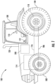
- FIG. 1 illustrates a side view of one embodiment of a work vehicle 100.
- the work vehicle 100 is configured as an agricultural tractor.
- the work vehicle 100 may be configured as any other suitable work vehicle known in the art, such as various other agricultural vehicles, earth-moving vehicles, road vehicles, all-terrain vehicles, off-road vehicles, loaders, and/or the like.
- the work vehicle 100 includes a pair of front wheels 102, a pair of rear wheels 104, and a chassis 106 coupled to and supported by the wheels 102, 104.
- An operator's cab 108 may be supported by a portion of the chassis 106 and may house various control devices 110, 112 (e.g., levers, pedals, control panels and/or the like) for permitting an operator to control the operation of the work vehicle 100.
- the work vehicle 100 may include an engine 114 and a transmission 116 mounted on the chassis 106.
- the transmission 116 may be operably coupled to the engine 114 and may provide variably adjusted gear ratios for transferring engine power to the wheels 104 via a differential 118.
- the work vehicle 100 may also include an exhaust treatment system 200 for reducing the amount of emissions contained within the exhaust from the engine 114.
- engine exhaust expelled from the engine 114 may be directed through the exhaust treatment system 200 to allow the levels of nitrogen oxide (NOx) emissions contained within the exhaust to be reduced significantly.
- the cleaned or treated exhaust gases may then be expelled from the exhaust treatment system 200 into the surrounding environment via an exhaust pipe 120 of the work vehicle 100.
- NOx nitrogen oxide
- the configuration of the work vehicle 100 described above and shown in FIG. 1 is provided only to place the present subject matter in an exemplary field of use.
- the present subject matter may be readily adaptable to any manner of work vehicle configuration 100.
- a separate frame or chassis may be provided to which the engine 114, transmission 116, and differential 118 are coupled, a configuration common in smaller tractors.
- Still other configurations may use an articulated chassis to steer the work vehicle 100, or rely on tracks in lieu of the wheels 102, 104.
- the work vehicle 100 may also be configured to be operably coupled to any suitable type of work implement, such as a trailer, spray boom, manure tank, feed grinder, plow and/or the like.
- the exhaust treatment system includes an exhaust conduit 202, a diesel oxidation catalyst (DOC) system 204, a mixing conduit 206, a selective catalytic reduction (SCR) system 208, and a treated exhaust flow conduit 210.
- DOC diesel oxidation catalyst
- SCR selective catalytic reduction
- the DOC system 204 is configured to reduce the levels of carbon monoxide and hydrocarbons present in the engine exhaust. For example, as shown in FIG.
- the DOC system 204 includes a canister or chamber 212 for receiving engine exhaust from the exhaust conduit 202, with the chamber 212 being in flow communication with an upstream end 214 of the mixing conduit 206.
- the DOC system 204 includes a reductant injector nozzle 216 provided in association with the chamber 212 at a location at or adjacent to the upstream end 214 of the mixing conduit 206 to allow an exhaust reductant 218, such as a diesel exhaust fluid (DEF) or any other suitable urea-based fluid, to be injected into the stream of exhaust gases flowing through the chamber 212.
- DEF diesel exhaust fluid
- the reductant injector nozzle 216 may be fluidly coupled to a source of exhaust reductant (e.g., storage tank 220) via a hose or other fluid coupling 222 to allow liquid exhaust reductant to be supplied to the nozzle 216.
- the engine exhaust and exhaust reductant flowing into the upstream end 214 of the mixing conduit 206 are then directed through the conduit 206 to the downstream end 224 thereof for receipt by the SCR system 208, within which the mixture of exhaust/reductant is reacted with a catalyst to generate a treated exhaust flow in which the amount of harmful or undesirable gas emissions has been reduced as compared to the engine exhaust initially discharged from the engine 114.
- the treated exhaust flow is then expelled from an outlet 230 of the SCR system 208 and is directed through the downstream flow conduit 210 for discharge into the atmosphere (e.g., via an exhaust pipe 120 forming part of or coupled to the downstream flow conduit 210).
- the exhaust treatment system 200 includes an exhaust sensor 250 positioned within the downstream flow conduit 210 to monitor the concentration or amount of emissions remaining within the treated exhaust flow following treatment within the SCR system 208.
- the exhaust sensor 250 comprises one or more nitrogen oxide (NOx) sensors configured to detect the amount of NOx contained within the treated exhaust flow.
- NOx nitrogen oxide
- the exhaust sensor 250 may comprise any other suitable sensor(s) or combination of sensor(s) configured to detect the concentration or amount of gaseous emissions contained within the treated exhaust flow, including the detection of gaseous emissions other than NOx and/or the detection of NOx in combination with one or more other gaseous emissions. As shown, in FIG.
- the exhaust sensor 250 is communicatively coupled to a controller 260 (e.g., a computing device or another other suitable processor-based device) configured to monitor the exhaust emissions contained within the treated exhaust flow based on the data received from the sensor 250.
- the controller 260 may then, for example, compare the concentration or amount of detected exhaust emissions to a predetermined limit or threshold and control one or more components of the work vehicle 100 based on such comparison, such as by adjusting the combustion temperature of the engine 114 and/or varying the amount of reductant injected into the DOC system 204 to ensure that the exhaust emissions remain below the predetermined limit or threshold.
- the exhaust treatment system 200 may also include a flow mixer 300 positioned at or adjacent to the outlet 230 of the SCR system 208.
- the flow mixer 300 may be configured to impart a rotating or spiraling flow trajectory to the treated exhaust flow expelled from the SCR system 208, which may facilitate enhanced mixing of the treated exhaust immediately upstream of the exhaust sensor 250, thereby allowing the sensor 250 to provide more accurate data related to the concentration or amount of the gaseous emission(s) (e.g., NOx) being monitored.
- the gaseous emission(s) e.g., NOx
- FIG. 3 a cross-sectional view of a portion of the exhaust treatment system shown in FIG. 2 within box 3-3 is illustrated in accordance with aspects of the present subject matter, particularly illustrating one embodiment of a flow mixer positioned relative to an outlet of the selective catalytic reduction (SCR) system.
- the flow mixer 300 is configured to be positioned at or adjacent to the outlet 230 of the SCR system 208.
- the flow mixer 300 is positioned immediately at the interface between the SCR outlet 230 and an adjacent upstream end 232 of the flow conduit 210.
- the flow mixer 300 generally extends between an upstream end 302 and a downstream end 304 along an axial direction L1.
- the downstream end 304 of the flow mixer 300 is configured to be positioned at or adjacent the outlet 230 of the SCR system 208 such that the downstream end 304 of the flow mixer 300 is positioned closer to the outlet 230 than the upstream end 302 of the flow mixer 300.
- the flow mixer 300 may be positioned at any other suitable location relative to the SCR outlet 230, such as at a location upstream of the interface between the SCR outlet 230 and the upstream end 232 of the flow conduit 210 or at a location downstream of the interface and upstream of the exhaust sensor 250.
- the exhaust sensor 250 may be configured to extend radially inwardly from an inner surface 234 of the flow conduit 210 such that at least a portion of the sensor 250 is positioned directly within and/or otherwise directly exposed to the flow of treated exhaust flowing downstream of the mixer 300.
- the exhaust sensor 250 is not shielded or otherwise protected from the flow of treated exhaust via an upstream deflector. Rather, a portion of the treated exhaust flow flows directly into and/or across the exhaust sensor 250 to allow the sensor 250 to provide accurate data relating to the gaseous emission(s) being monitored.
- the flow mixer 300 has a plurality of openings through which exhaust gases flow before reaching the exhaust sensor 250, and a plurality of vanes for creating a swirling trajectory of the exhaust gases flowing through the flow mixer 300.
- a first portion F1 and a second portion F2 of the treated exhaust flow expelled from the SCR system 208 may flow through openings at the upstream end 302 of the flow mixer 300, while a third portion F3 of the treated exhaust flow expelled from the SCR system 208 may flow through openings along a sidewall of the flow mixer 300.
- the first portion F1 of the exhaust gases may impinge on swirler vanes proximate the openings at the upstream end 302 such that the first portion F1 of the exhaust gases is given a swirling trajectory.
- the second portion F2 of the exhaust gases may generally flow past the ends of swirler vanes, which also at least partially prevents the third portion F3 of the exhaust gases from being drawn through the swirler vanes.
- the swirling trajectory of the first portion F1 of the exhaust gases helps to mix the first portion F1 with the other portions F2, F3 of the exhaust gases, while very little backflow pressure is created by the flow mixer 300.
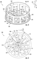
- FIGS. 4-6 differing views of the flow mixer 300 are illustrated in accordance with the present subject matter. Specifically, FIG. 4 illustrates a perspective view of the flow mixer 300, FIG. 5 illustrates a bottom view of the flow mixer 300, and FIG. 6 illustrates a side view of the flow mixer 300. As shown in FIGS. 4-6 , the mixer 300 includes an end wall 306 and a sidewall 308 coupled to the end wall 306, proximate the upstream end 302 of the mixer 300.
- the end wall 306 defines a plurality of sector openings 310.
- Each of the sector openings 310 extends in a circumferential direction CD1 between a first sector side 312 and a second sector side 314 and extends in a radial direction R1 between a radially inner sector end 316 and a radially outer sector end 318 across a first radial distance D1 ( FIG. 5 ).
- CD1 circumferential direction
- R1 between a radially inner sector end 316 and a radially outer sector end 318 across a first radial distance D1 ( FIG. 5 ).
- the first sector side 312 of each sector opening 310 extends at a first angle B1 relative to the second sector side 314 such that each sector opening 310 forms a wedge shape, with the sector sides 312, 314 being closer together at the radially inner sector end 316 than at the radially outer sector end 318.
- the radially inner sector ends 316 of the sector openings 310 are spaced apart radially from a center axis C1 by a gap distance GD.
- the sector openings 310 are evenly spaced apart in the circumferential direction CD1 by an angle B2 about the center axis C1 of the end wall 306.
- the sector openings 310 may be spaced apart by varying angles about the center axis C1.
- the angle B1 between the first and second sector sides 312, 314 is equal to the angle B2 between sector openings 310.
- the angles B1, B2 may be different from each other.
- the end wall 306 is shown as defining eight sector openings 310, the end wall 306 may define any other suitable number of sector openings 310.
- the end wall 306 may instead define two, three, four, five, six, eight or more sector openings 310.
- the sector openings 310 collectively cover between about 50% and about 70% of the end wall 306, such as between about 55% and about 65% of the end wall 306, such as about 60% of the end wall 306.
- the end wall 306 includes a plurality of swirler vanes 320 configured to impart a rotating or spiraling flow trajectory to the treated exhaust flow expelled from the SCR system 208 ( FIG. 3 ).
- Each of the swirler vanes 320 is associated with a respective one of the sector openings 310.
- each swirler vane 320 extends from the first sector side 312 of a respective sector opening 310 at an angle B3 ( FIGS. 3 and 4 ), such that the swirler vanes 320 extend toward the downstream end 304 of the flow mixer 300 and at least partially vertically above the respective sector opening 310.
- the angle B3 between the sector openings 310 and the swirler vanes 320 is about 45°.
- the swirler vanes 320 may be oriented at any other suitable angle relative to the sector openings 310.
- each swirler vane 320 (also referred to herein as simply “vane 320”) extends in the circumferential direction CD1 between a first vane side 322 and a second vane side 324 and extends in the radial direction R1 between a radially inner vane end 326 and a radially outer vane end 328 over a second radial distance D2 ( FIG. 5 ).
- a width of each vane 320 between the first and second vane sides 322, 324 corresponds to a width of the respective sector opening 310 between the first and second sector sides 312, 314 along the second radial distance D2 such that the vane 320 would extend fully across the width of the sector opening 310 in the circumferential direction if the vane 320 was not angled relative to the end wall 306 (e.g., at angle B3).
- the first vane side 322 of each vane 320 is adjacent the first sector side 312 of the respective sector opening 310.
- the radially inner vane end 326 of the first vane side 322 of each vane 320 may be at the radially inner sector end 316 of the first sector side 312 of the respective sector opening 310.
- each vane 320 is spaced apart from the radially outer sector end 318 of the respective sector opening 310.
- the second radial distance D2 ( FIG. 5 ) is about 80% of the first radial distance D1 ( FIG. 5 ).
- the first portion F1 of the treated exhaust flow expelled from the SCR system 208 ( FIG.
- the second portion F2 of the treated exhaust flow bypasses the vanes 320
- the second portion F2 has a more linear trajectory, which helps to at least partially reduce or avoid backpressure of the flow mixer 300.
- the swirling trajectory of the first portion F1 causes the second portion F2 to mix into the first portion F1.
- the number of vanes 320 generally matches the number of sector openings 310 such that each sector opening 310 is associated with a respective vane 320.
- the number of sector openings 310 may be greater than the number of vanes 320 such that some of the sector openings 310 may not have an associated vane 320.
- a higher number of vanes 320 may have a better mixing performance than a smaller number of vanes 320 with the same, total surface area.
- the sidewall 308 generally extends between the upstream end 302 and the downstream end 304 of the flow mixer 300. Particularly, the sidewall 308 extends between a first axial sidewall end 330 and a second axial sidewall end 332, with the first axial sidewall end 330 being proximate the upstream end 302 of the flow mixer 300 and the second axial end 332 being proximate the downstream end 304 of the flow mixer.
- the end wall 306 is coupled to the sidewall 308 at the first axial sidewall end 330.
- the sidewall 308 is annular or cylindrical. However, it should be appreciated that the sidewall 308 may have any other suitable shape.
- the sidewall 308 defines a plurality of sidewall openings 340 through which the third portion F3 ( FIG. 3 ) of the treated exhaust flow expelled from the SCR system 208 ( FIG. 3 ) may flow.
- Each of the sidewall openings 340 extends in the circumferential direction CD1 between a first sidewall side 342 and a second sidewall side 344, and in the axial direction L1 between a first axial sidewall end 346 and a second axial sidewall end 348 over a first axial range A1.
- the first and second sidewall sides 342, 344 are parallel to the axial direction L1, while the first and second axial sidewall ends 346, 348 are generally perpendicular to the axial direction L1. As shown in FIG.
- each of the sector openings 310 is associated with one or more of the sidewall openings 340.
- each of the sector openings 310 is at least partially radially aligned with one or more of the sidewall openings 340.
- the sidewall 308 includes eleven sidewall openings 340 evenly spaced apart about the center axis C1 of the flow mixer 300 in the circumferential direction CD1.
- the sidewall 308 may include any other suitable number of sidewall openings 340.
- the sidewall openings 340 collectively cover between about 40% and about 50% of the sidewall 308, such as about 45% of the sidewall 308. It should be appreciated that, as will be described below, the total coverage percentages of the sidewall openings 340 and the sector openings 310 are selected such that the portions of treated exhaust flow through the end wall 306 and the sidewall 308 are approximately equal.
- the vanes 320 are angled relative to the end wall 306 such that each vane 320 extends in the axial direction L1 from the end wall 306 along a second axial range A2.
- the sidewall openings 340 are positioned such that the first and second axial ranges A1 and A2 at least partially overlap.
- the second axial sidewall end 348 of each of the sidewall openings 340 may be spaced axially apart from the radially outer vane ends 328 along the axial direction L1 such that the first axial range A1 extends closer to the downstream end 304 of the flow mixer 300 than the second axial range A2.
- the third portion F3 of the treated exhaust flow may enter the flow mixer 300 in the axial gap defined between the radially outer vane ends 328 of the vanes 320 and the second axial sidewall ends 348 of the sidewall openings 340, thereby avoiding the vanes 320.
- the remaining part of the third portion F3 of the treated exhaust flow that enters the flow mixer 300 at the vanes 320 may be at least partially guided away from the vanes 320 by the second portion F2 of the treated exhaust flow flowing past the ends of the vanes 320.
- the second and third portions F2 may mix at the sidewall openings 340, while further mixing with the first portion F1 at a location closer to the downstream end 304 of the flow mixer 300.
- the flow mixer 300 may also be utilized in one or more additional locations within the exhaust treatment system 200.
- the flow mixer 300 may be positioned within the mixing conduit 206 (e.g., at a location between the upstream and downstream ends 214, 224 of the mixing conduit 206) extending between the DOC system 204 and the SCR system 208, such as at the location indicated by dashed lines 300A in FIG. 2 .
- the flow mixer 300 may be used to impart spiraling flow trajectories to the reductant/exhaust flow expelled from the DOC system 204 to facilitate proper mixing of the reductant and engine exhaust prior to such flow being directed into the SCR system 208.
Landscapes
- Chemical & Material Sciences (AREA)
- Engineering & Computer Science (AREA)
- Chemical Kinetics & Catalysis (AREA)
- Combustion & Propulsion (AREA)
- Health & Medical Sciences (AREA)
- Mechanical Engineering (AREA)
- General Engineering & Computer Science (AREA)
- Analytical Chemistry (AREA)
- Toxicology (AREA)
- Biomedical Technology (AREA)
- Environmental & Geological Engineering (AREA)
- General Chemical & Material Sciences (AREA)
- Oil, Petroleum & Natural Gas (AREA)
- Dispersion Chemistry (AREA)
- Exhaust Gas After Treatment (AREA)
Abstract
Description
- The present subject matter relates generally to the treatment of engine exhaust gases, and more particularly, to exhaust treatment systems of work vehicles for improving mixing of exhaust gases before the exhaust gases reach an exhaust sensor, such as a nitrogen oxide (NOx) sensor. In addition, the present subject matter relates to flow mixer configurations for use within an exhaust treatment system for a work vehicle.
- Typically, work vehicles, such as tractors and other agricultural vehicles, include an exhaust treatment system for controlling engine emissions. As is generally understood, exhaust treatment systems for work vehicles often include a diesel oxidation catalyst (DOC) system in fluid communication with a selective catalytic reduction (SCR) system. The DOC system is generally configured to oxidize carbon monoxide and unburnt hydrocarbons contained within the engine exhaust and may include a mixing chamber for mixing an exhaust reductant, such as a diesel exhaust fluid (DEF) or any other suitable urea-based fluid, into the engine exhaust. For instance, the exhaust reductant is often pumped from a reductant tank mounted on and/or within the vehicle and injected into the mixing chamber to mix the reductant with the engine exhaust. The resulting mixture may then be supplied to the SCR system to allow the reductant to be reacted with a catalyst in order to reduce the amount of nitrogen oxide (NOx) emissions contained within the engine exhaust. A NOx sensor is typically positioned downstream of the SCR system to monitor the amount of NOx emissions still remaining in the exhaust flow exiting the exhaust treatment system. The data from the sensor may, for example, be used to control the combustion temperature of the engine and/or the amount of reductant injected into the mixing chamber to ensure that the amount of NOx emissions remains below a given amount.
- In many instances, the NOx sensor is positioned close to the outlet of the SCR system. As such, the exhaust gases from different substrate channels do not have time to sufficiently mix before reaching the NOx sensor. As such, the NOx sensor tends to read exhaust gases from only one substrate channel, which significantly reduces the accuracy of the sensor readings and thus, the overall performance of the treatment system.
- Accordingly, an improved exhaust treatment system for work vehicles and related flow mixers would be welcomed in the technology.
- Aspects and advantages of the invention will be set forth in part in the following description, or may be obvious from the description, or may be learned through practice of the invention.
- In one aspect, the present subject matter is directed to an exhaust treatment system for a work vehicle. The system may include a selective catalytic reduction (SCR) system configured to react a mixture of exhaust reductant and engine exhaust with a catalyst to generate a treated exhaust flow, with the SCR system including an SCR outlet for expelling the treated exhaust flow therefrom. The system may further include a flow conduit in fluid communication with the SCR outlet for receiving the treated exhaust flow expelled from the SCR system. Further, the system may include an exhaust sensor positioned within the flow conduit downstream of the SCR outlet, with the exhaust sensor being configured to detect an amount of an emission gas present in the treated exhaust flow. Additionally, the system may include a flow mixer positioned upstream of the exhaust sensor. The flow mixer may have an end wall defining sector openings extending in a circumferential direction of the flow mixer between a first sector side and a second sector side and in a radial direction of the flow mixer between a radially inner sector end and a radially outer sector end. Moreover, the flow mixer may have a plurality of swirler vanes, where each of the plurality of swirler vanes extends in the circumferential direction from the first sector side of a respective one of the sector openings and in the radial direction between a radially inner vane end and a radially outer vane end. Particularly, the radially outer vane end of each of the plurality of swirler vanes may be spaced apart in the radial direction from the radially outer sector end of the respective one of the sector openings. As such, the plurality of swirler vanes is configured to impart a spiraling flow trajectory to the treated exhaust flow flowing from the SCR to the exhaust sensor.
- In another aspect, the present subject matter is directed to an exhaust treatment system for a work vehicle. The system may include a selective catalytic reduction (SCR) system configured to react a mixture of exhaust reductant and engine exhaust with a catalyst to generate a treated exhaust flow, where the SCR system includes an SCR outlet for expelling the treated exhaust flow therefrom. The system may further include a flow conduit in fluid communication with the SCR outlet for receiving the treated exhaust flow expelled from the SCR system. Further, the system may include an exhaust sensor positioned within the flow conduit downstream of the SCR outlet, with the exhaust sensor being configured to detect an amount of an emission gas present in the treated exhaust flow. Additionally, the system may include a flow mixer positioned upstream of the exhaust sensor, with the flow mixer extending between an upstream end and a downstream end along an axial direction. The flow mixer may have a sidewall extending between the upstream and downstream ends, with the sidewall defining a plurality of sidewall openings. Each of the plurality of sidewall openings may extend in the axial direction across a first axial range. Further, the flow mixer may have an end wall coupled to the sidewall proximate the upstream end, the end wall defining sector openings. Additionally, the flow mixer may have a plurality of swirler vanes, where each of the plurality of swirler vanes extends in a circumferential direction of the flow mixer from adjacent a respective one of the sector openings and in the axial direction across a second axial range, with the first axial range at least partially overlapping the second axial range. The plurality of swirler vanes is configured to impart a spiraling flow trajectory to the treated exhaust flow flowing from the SCR to the exhaust sensor.
- In an additional aspect, the present subject matter is directed to a flow mixer for use within an exhaust treatment system of a work vehicle. The flow mixer may have a sidewall extending between an upstream end and a downstream end along an axial direction, where the sidewall defines a plurality of sidewall openings. Each of the plurality of sidewall openings extends in the axial direction across a first axial range. Further, the flow mixer may include an end wall coupled to the sidewall proximate the upstream end, with the end wall defining sector openings extending in a radial direction of the flow mixer across a first radial distance. Additionally, the flow mixer may have a plurality of swirler vanes, with each of the plurality of swirler vanes extending in a circumferential direction of the flow mixer from a respective one of the sector openings and in the radial direction across a second radial distance and in the axial direction across a second axial range. Particularly, the second radial distance is less than the first radial distance, and the first axial range at least partially overlaps the second axial range.
- These and other features, aspects and advantages of the present invention will become better understood with reference to the following description and appended claims. The accompanying drawings, which are incorporated in and constitute a part of this specification, illustrate embodiments of the invention and, together with the description, serve to explain the principles of the invention.
- A full and enabling disclosure of the present invention, including the best mode thereof, directed to one of ordinary skill in the art, is set forth in the specification, which makes reference to the appended figures, in which:
-
FIG. 1 illustrates a side view of one embodiment of a work vehicle in accordance with aspects of the present subject matter; -
FIG. 2 illustrates a schematic view of one embodiment of an exhaust treatment system suitable for use with a work vehicle in accordance with aspects of the present subject matter; -
FIG. 3 illustrates a simplified, cross-sectional view of a portion of the exhaust treatment system shown inFIG. 2 within box 3-3, particularly illustrating one embodiment of a flow mixer positioned relative to an outlet of the selective catalytic reduction (SCR) system in accordance with aspects of the present subject matter; -
FIG. 4 illustrates a perspective view of one embodiment of a flow mixer suitable for the disclosed exhaust treatment system shown inFIG. 2 in accordance with aspects of the present subject matter; -
FIG. 5 illustrates a bottom view of the flow mixer shown inFIG. 4 in accordance with aspects of the present subject matter; and -
FIG. 6 illustrates a side view of the flow mixer shown inFIG. 4 in accordance with aspects of the present subject matter. - Repeat use of reference characters in the present specification and drawings is intended to represent the same or analogous features or elements of the present technology.
- Reference now will be made in detail to embodiments of the invention, one or more examples of which are illustrated in the drawings. Each example is provided by way of explanation of the invention, not limitation of the invention. In fact, it will be apparent to those skilled in the art that various modifications and variations can be made in the present invention. For instance, features illustrated or described as part of one embodiment can be used with another embodiment to yield a still further embodiment. Thus, it is intended that the present invention covers such modifications and variations as come within the scope of the appended claims and their equivalents.
- In general, the present subject matter is directed to an exhaust treatment system for a work vehicle. In several embodiments, the exhaust treatment system includes a flow mixer adapted to increase the mixing of exhaust gases from different substrate channels exiting a selective catalytic reduction (SCR) system before the exhaust gases reach a sensor, such as a nitrogen oxide (NOx) sensor. For example, the flow mixer may be positioned at a location upstream of the exhaust sensor such that the mixer imparts a spiraling flow trajectory to the flow of treated exhaust from the SCR system. In one embodiment, the flow mixer has an end wall that defines a plurality of sector openings. The flow mixer further has swirler vanes, where each of the swirler vanes extends from a respective one of the plurality of sector openings. Particularly, in some embodiments, each swirler vane only extends over part of the radial distance across which the respective sector openings extends. For example, in some embodiments, a radially outer end of each of the vanes may be spaced apart from a radial outer end of the respective one of the plurality of sector openings. Further, the flow mixer may include a sidewall extending between the upstream and downstream ends, where the sidewall similarly defines a plurality of circumferentially spaced sidewall openings. The sidewall openings and the vanes at least partially overlap along an axial direction of the flow mixer. The end wall, in such embodiments, may be coupled to the sidewall proximate an upstream end of the flow mixer.
- Exhaust gases may flow through the sector openings and the sidewall openings to exit the SCR system, where the swirler vanes create a spiral flow of the exhaust gases to better mix the exhaust gases before the exhaust gases flow past the exhaust sensor. As such, the NOx sensor may more accurately monitor the amount of NOx emissions remaining in the exhaust flow based at least in part on the mixed exhaust gases. Additionally, due to the relatively open configuration of the flow mixer by having such sector and sidewall openings, mixing of the exhaust gases is accomplished with very little backpressure being created in the exhaust treatment system.
- Referring now to the drawings,
FIG. 1 illustrates a side view of one embodiment of awork vehicle 100. As shown, thework vehicle 100 is configured as an agricultural tractor. However, in other embodiments, thework vehicle 100 may be configured as any other suitable work vehicle known in the art, such as various other agricultural vehicles, earth-moving vehicles, road vehicles, all-terrain vehicles, off-road vehicles, loaders, and/or the like. - As shown in
FIG. 1 , thework vehicle 100 includes a pair offront wheels 102, a pair ofrear wheels 104, and achassis 106 coupled to and supported by thewheels cab 108 may be supported by a portion of thechassis 106 and may housevarious control devices 110, 112 (e.g., levers, pedals, control panels and/or the like) for permitting an operator to control the operation of thework vehicle 100. Additionally, thework vehicle 100 may include anengine 114 and atransmission 116 mounted on thechassis 106. Thetransmission 116 may be operably coupled to theengine 114 and may provide variably adjusted gear ratios for transferring engine power to thewheels 104 via a differential 118. - Moreover, the
work vehicle 100 may also include anexhaust treatment system 200 for reducing the amount of emissions contained within the exhaust from theengine 114. For instance, engine exhaust expelled from theengine 114 may be directed through theexhaust treatment system 200 to allow the levels of nitrogen oxide (NOx) emissions contained within the exhaust to be reduced significantly. The cleaned or treated exhaust gases may then be expelled from theexhaust treatment system 200 into the surrounding environment via anexhaust pipe 120 of thework vehicle 100. - It should be appreciated that the configuration of the
work vehicle 100 described above and shown inFIG. 1 is provided only to place the present subject matter in an exemplary field of use. Thus, it should be appreciated that the present subject matter may be readily adaptable to any manner ofwork vehicle configuration 100. For example, in an alternative embodiment, a separate frame or chassis may be provided to which theengine 114,transmission 116, and differential 118 are coupled, a configuration common in smaller tractors. Still other configurations may use an articulated chassis to steer thework vehicle 100, or rely on tracks in lieu of thewheels work vehicle 100 may also be configured to be operably coupled to any suitable type of work implement, such as a trailer, spray boom, manure tank, feed grinder, plow and/or the like. - Referring now to
FIG. 2 , a schematic diagram of one embodiment of anexhaust treatment system 200 suitable for use with awork vehicle 100 is illustrated in accordance with aspects of the present subject matter. As represented inFIG. 2 , the exhaust treatment system includes anexhaust conduit 202, a diesel oxidation catalyst (DOC)system 204, a mixingconduit 206, a selective catalytic reduction (SCR)system 208, and a treatedexhaust flow conduit 210. During operation of thework vehicle 100, exhaust expelled from theengine 114 is received by theexhaust conduit 202 and flows through theconduit 202 to theDOC system 204. As is generally understood, theDOC system 204 is configured to reduce the levels of carbon monoxide and hydrocarbons present in the engine exhaust. For example, as shown inFIG. 2 , theDOC system 204 includes a canister orchamber 212 for receiving engine exhaust from theexhaust conduit 202, with thechamber 212 being in flow communication with anupstream end 214 of the mixingconduit 206. In addition, theDOC system 204 includes areductant injector nozzle 216 provided in association with thechamber 212 at a location at or adjacent to theupstream end 214 of the mixingconduit 206 to allow anexhaust reductant 218, such as a diesel exhaust fluid (DEF) or any other suitable urea-based fluid, to be injected into the stream of exhaust gases flowing through thechamber 212. For instance, as shown inFIG. 2 , thereductant injector nozzle 216 may be fluidly coupled to a source of exhaust reductant (e.g., storage tank 220) via a hose or otherfluid coupling 222 to allow liquid exhaust reductant to be supplied to thenozzle 216. The engine exhaust and exhaust reductant flowing into theupstream end 214 of the mixingconduit 206 are then directed through theconduit 206 to thedownstream end 224 thereof for receipt by theSCR system 208, within which the mixture of exhaust/reductant is reacted with a catalyst to generate a treated exhaust flow in which the amount of harmful or undesirable gas emissions has been reduced as compared to the engine exhaust initially discharged from theengine 114. The treated exhaust flow is then expelled from anoutlet 230 of theSCR system 208 and is directed through thedownstream flow conduit 210 for discharge into the atmosphere (e.g., via anexhaust pipe 120 forming part of or coupled to the downstream flow conduit 210). - Additionally, as shown in
FIG. 2 , theexhaust treatment system 200 includes anexhaust sensor 250 positioned within thedownstream flow conduit 210 to monitor the concentration or amount of emissions remaining within the treated exhaust flow following treatment within theSCR system 208. In one embodiment, theexhaust sensor 250 comprises one or more nitrogen oxide (NOx) sensors configured to detect the amount of NOx contained within the treated exhaust flow. However, in other embodiments, theexhaust sensor 250 may comprise any other suitable sensor(s) or combination of sensor(s) configured to detect the concentration or amount of gaseous emissions contained within the treated exhaust flow, including the detection of gaseous emissions other than NOx and/or the detection of NOx in combination with one or more other gaseous emissions. As shown, inFIG. 2 , in one embodiment, theexhaust sensor 250 is communicatively coupled to a controller 260 (e.g., a computing device or another other suitable processor-based device) configured to monitor the exhaust emissions contained within the treated exhaust flow based on the data received from thesensor 250. Thecontroller 260 may then, for example, compare the concentration or amount of detected exhaust emissions to a predetermined limit or threshold and control one or more components of thework vehicle 100 based on such comparison, such as by adjusting the combustion temperature of theengine 114 and/or varying the amount of reductant injected into theDOC system 204 to ensure that the exhaust emissions remain below the predetermined limit or threshold. - Moreover, the
exhaust treatment system 200 may also include aflow mixer 300 positioned at or adjacent to theoutlet 230 of theSCR system 208. As will be described in greater detail below, theflow mixer 300 may be configured to impart a rotating or spiraling flow trajectory to the treated exhaust flow expelled from theSCR system 208, which may facilitate enhanced mixing of the treated exhaust immediately upstream of theexhaust sensor 250, thereby allowing thesensor 250 to provide more accurate data related to the concentration or amount of the gaseous emission(s) (e.g., NOx) being monitored. - Referring now to
FIG. 3 , a cross-sectional view of a portion of the exhaust treatment system shown inFIG. 2 within box 3-3 is illustrated in accordance with aspects of the present subject matter, particularly illustrating one embodiment of a flow mixer positioned relative to an outlet of the selective catalytic reduction (SCR) system. As indicated above, in several embodiments, theflow mixer 300 is configured to be positioned at or adjacent to theoutlet 230 of theSCR system 208. For example, in the illustrated embodiment, theflow mixer 300 is positioned immediately at the interface between theSCR outlet 230 and an adjacent upstream end 232 of theflow conduit 210. Theflow mixer 300 generally extends between anupstream end 302 and adownstream end 304 along an axial direction L1. Thedownstream end 304 of theflow mixer 300 is configured to be positioned at or adjacent theoutlet 230 of theSCR system 208 such that thedownstream end 304 of theflow mixer 300 is positioned closer to theoutlet 230 than theupstream end 302 of theflow mixer 300. However, in other embodiments, theflow mixer 300 may be positioned at any other suitable location relative to theSCR outlet 230, such as at a location upstream of the interface between theSCR outlet 230 and the upstream end 232 of theflow conduit 210 or at a location downstream of the interface and upstream of theexhaust sensor 250. - Additionally, as shown in
FIG. 3 , theexhaust sensor 250 may be configured to extend radially inwardly from aninner surface 234 of theflow conduit 210 such that at least a portion of thesensor 250 is positioned directly within and/or otherwise directly exposed to the flow of treated exhaust flowing downstream of themixer 300. In this regard, it should be noted that theexhaust sensor 250 is not shielded or otherwise protected from the flow of treated exhaust via an upstream deflector. Rather, a portion of the treated exhaust flow flows directly into and/or across theexhaust sensor 250 to allow thesensor 250 to provide accurate data relating to the gaseous emission(s) being monitored. - As will be described below in greater detail, the
flow mixer 300 has a plurality of openings through which exhaust gases flow before reaching theexhaust sensor 250, and a plurality of vanes for creating a swirling trajectory of the exhaust gases flowing through theflow mixer 300. For instance, a first portion F1 and a second portion F2 of the treated exhaust flow expelled from theSCR system 208 may flow through openings at theupstream end 302 of theflow mixer 300, while a third portion F3 of the treated exhaust flow expelled from theSCR system 208 may flow through openings along a sidewall of theflow mixer 300. The first portion F1 of the exhaust gases may impinge on swirler vanes proximate the openings at theupstream end 302 such that the first portion F1 of the exhaust gases is given a swirling trajectory. The second portion F2 of the exhaust gases may generally flow past the ends of swirler vanes, which also at least partially prevents the third portion F3 of the exhaust gases from being drawn through the swirler vanes. The swirling trajectory of the first portion F1 of the exhaust gases helps to mix the first portion F1 with the other portions F2, F3 of the exhaust gases, while very little backflow pressure is created by theflow mixer 300. - Referring now to
FIGS. 4-6 , differing views of theflow mixer 300 are illustrated in accordance with the present subject matter. Specifically,FIG. 4 illustrates a perspective view of theflow mixer 300,FIG. 5 illustrates a bottom view of theflow mixer 300, andFIG. 6 illustrates a side view of theflow mixer 300. As shown inFIGS. 4-6 , themixer 300 includes anend wall 306 and asidewall 308 coupled to theend wall 306, proximate theupstream end 302 of themixer 300. - As particularly shown in
FIGS. 4 and 5 , theend wall 306 defines a plurality ofsector openings 310. Each of thesector openings 310 extends in a circumferential direction CD1 between afirst sector side 312 and asecond sector side 314 and extends in a radial direction R1 between a radiallyinner sector end 316 and a radiallyouter sector end 318 across a first radial distance D1 (FIG. 5 ). As particularly shown inFIG. 5 , thefirst sector side 312 of eachsector opening 310 extends at a first angle B1 relative to thesecond sector side 314 such that each sector opening 310 forms a wedge shape, with the sector sides 312, 314 being closer together at the radiallyinner sector end 316 than at the radiallyouter sector end 318. The radially inner sector ends 316 of thesector openings 310 are spaced apart radially from a center axis C1 by a gap distance GD. In some embodiments, thesector openings 310 are evenly spaced apart in the circumferential direction CD1 by an angle B2 about the center axis C1 of theend wall 306. However, in one or more embodiments, thesector openings 310 may be spaced apart by varying angles about the center axis C1. In one embodiment, the angle B1 between the first and second sector sides 312, 314 is equal to the angle B2 betweensector openings 310. However, in other embodiments, the angles B1, B2 may be different from each other. - It should be appreciated that while the
end wall 306 is shown as defining eightsector openings 310, theend wall 306 may define any other suitable number ofsector openings 310. For instance, theend wall 306 may instead define two, three, four, five, six, eight ormore sector openings 310. Preferably, in some embodiments, thesector openings 310 collectively cover between about 50% and about 70% of theend wall 306, such as between about 55% and about 65% of theend wall 306, such as about 60% of theend wall 306. - As further shown in
FIGS. 4-6 , theend wall 306 includes a plurality ofswirler vanes 320 configured to impart a rotating or spiraling flow trajectory to the treated exhaust flow expelled from the SCR system 208 (FIG. 3 ). Each of theswirler vanes 320 is associated with a respective one of thesector openings 310. For instance, eachswirler vane 320 extends from thefirst sector side 312 of a respective sector opening 310 at an angle B3 (FIGS. 3 and4 ), such that theswirler vanes 320 extend toward thedownstream end 304 of theflow mixer 300 and at least partially vertically above therespective sector opening 310. For instance, the angle B3 between thesector openings 310 and theswirler vanes 320 is about 45°. However, it should be appreciated that theswirler vanes 320 may be oriented at any other suitable angle relative to thesector openings 310. - As particularly shown in
FIGS. 4 and 5 , each swirler vane 320 (also referred to herein as simply "vane 320") extends in the circumferential direction CD1 between afirst vane side 322 and asecond vane side 324 and extends in the radial direction R1 between a radiallyinner vane end 326 and a radiallyouter vane end 328 over a second radial distance D2 (FIG. 5 ). In one embodiment, a width of eachvane 320 between the first and second vane sides 322, 324 corresponds to a width of the respective sector opening 310 between the first and second sector sides 312, 314 along the second radial distance D2 such that thevane 320 would extend fully across the width of thesector opening 310 in the circumferential direction if thevane 320 was not angled relative to the end wall 306 (e.g., at angle B3). Thefirst vane side 322 of eachvane 320 is adjacent thefirst sector side 312 of therespective sector opening 310. Additionally, in one embodiment, the radiallyinner vane end 326 of thefirst vane side 322 of eachvane 320 may be at the radiallyinner sector end 316 of thefirst sector side 312 of therespective sector opening 310. - In some embodiments, the radially
outer vane end 328 of eachvane 320 is spaced apart from the radiallyouter sector end 318 of therespective sector opening 310. For instance, in one embodiment, the second radial distance D2 (FIG. 5 ) is about 80% of the first radial distance D1 (FIG. 5 ). In such embodiments, the first portion F1 of the treated exhaust flow expelled from the SCR system 208 (FIG. 3 ) flows through a first portion ofsector openings 310 that overlaps with the second radial distance D2, such that the first portion of the treated exhaust flow is given a counter-clockwise rotating or spiraling flow trajectory as it is guided by thevanes 320, while the second portion F2 of the treated exhaust flow expelled from the SCR system 208 (FIG. 3 ) may flow through a second portion of thesector openings 310 that does not overlap with the second radial distance D2, such that the second portion of the treated exhaust flow flows past the radially outer vane ends 328 of thevanes 320. As the second portion F2 of the treated exhaust flow bypasses thevanes 320, the second portion F2 has a more linear trajectory, which helps to at least partially reduce or avoid backpressure of theflow mixer 300. The swirling trajectory of the first portion F1 causes the second portion F2 to mix into the first portion F1. - In some embodiments, such as the embodiment illustrated, the number of
vanes 320 generally matches the number ofsector openings 310 such that eachsector opening 310 is associated with arespective vane 320. However, it should be appreciated that, in some embodiments, the number ofsector openings 310 may be greater than the number ofvanes 320 such that some of thesector openings 310 may not have an associatedvane 320. Additionally, it should be appreciated that, in general, a higher number ofvanes 320 may have a better mixing performance than a smaller number ofvanes 320 with the same, total surface area. - As shown in
FIGS. 4 and6 , thesidewall 308 generally extends between theupstream end 302 and thedownstream end 304 of theflow mixer 300. Particularly, thesidewall 308 extends between a firstaxial sidewall end 330 and a second axial sidewall end 332, with the firstaxial sidewall end 330 being proximate theupstream end 302 of theflow mixer 300 and the second axial end 332 being proximate thedownstream end 304 of the flow mixer. Theend wall 306 is coupled to thesidewall 308 at the firstaxial sidewall end 330. In one embodiment, thesidewall 308 is annular or cylindrical. However, it should be appreciated that thesidewall 308 may have any other suitable shape. - The
sidewall 308 defines a plurality ofsidewall openings 340 through which the third portion F3 (FIG. 3 ) of the treated exhaust flow expelled from the SCR system 208 (FIG. 3 ) may flow. Each of thesidewall openings 340 extends in the circumferential direction CD1 between afirst sidewall side 342 and asecond sidewall side 344, and in the axial direction L1 between a firstaxial sidewall end 346 and a secondaxial sidewall end 348 over a first axial range A1. In one embodiment, the first and second sidewall sides 342, 344 are parallel to the axial direction L1, while the first and second axial sidewall ends 346, 348 are generally perpendicular to the axial direction L1. As shown inFIG. 4 , each of thesector openings 310 is associated with one or more of thesidewall openings 340. For instance, in one embodiment, each of thesector openings 310 is at least partially radially aligned with one or more of thesidewall openings 340. In one embodiment, such as the embodiment shown, thesidewall 308 includes elevensidewall openings 340 evenly spaced apart about the center axis C1 of theflow mixer 300 in the circumferential direction CD1. However, in other embodiments, thesidewall 308 may include any other suitable number ofsidewall openings 340. Preferably, in some embodiments, thesidewall openings 340 collectively cover between about 40% and about 50% of thesidewall 308, such as about 45% of thesidewall 308. It should be appreciated that, as will be described below, the total coverage percentages of thesidewall openings 340 and thesector openings 310 are selected such that the portions of treated exhaust flow through theend wall 306 and thesidewall 308 are approximately equal. - Further, as particularly shown in
FIG. 6 , thevanes 320 are angled relative to theend wall 306 such that eachvane 320 extends in the axial direction L1 from theend wall 306 along a second axial range A2. In one embodiment, thesidewall openings 340 are positioned such that the first and second axial ranges A1 and A2 at least partially overlap. Particularly, the secondaxial sidewall end 348 of each of thesidewall openings 340 may be spaced axially apart from the radially outer vane ends 328 along the axial direction L1 such that the first axial range A1 extends closer to thedownstream end 304 of theflow mixer 300 than the second axial range A2. As such, at least part of the third portion F3 of the treated exhaust flow may enter theflow mixer 300 in the axial gap defined between the radially outer vane ends 328 of thevanes 320 and the second axial sidewall ends 348 of thesidewall openings 340, thereby avoiding thevanes 320. In some embodiments, the remaining part of the third portion F3 of the treated exhaust flow that enters theflow mixer 300 at thevanes 320 may be at least partially guided away from thevanes 320 by the second portion F2 of the treated exhaust flow flowing past the ends of thevanes 320. As such, the second and third portions F2 may mix at thesidewall openings 340, while further mixing with the first portion F1 at a location closer to thedownstream end 304 of theflow mixer 300. By allowing the second and third portions F2, F3 of the exhaust gases to at least partially avoid thevanes 320, backpressure of theSCR system 208 is at least partially avoided or reduced. - It should be appreciated that, although the mixer configuration shown in
FIGS. 4-6 is generally described herein with reference to mixing the flow of exhaust gases directed between theSCR system 208 and thedownstream exhaust sensor 250, theflow mixer 300 may also be utilized in one or more additional locations within theexhaust treatment system 200. For instance, in addition to being located between theSCR system 208 and the downstream exhaust sensor 250 (or as an alternative thereto), theflow mixer 300 may be positioned within the mixing conduit 206 (e.g., at a location between the upstream and downstream ends 214, 224 of the mixing conduit 206) extending between theDOC system 204 and theSCR system 208, such as at the location indicated by dashedlines 300A inFIG. 2 . In such an embodiment, theflow mixer 300 may be used to impart spiraling flow trajectories to the reductant/exhaust flow expelled from theDOC system 204 to facilitate proper mixing of the reductant and engine exhaust prior to such flow being directed into theSCR system 208. - It should additionally be appreciated that, throughout the description, "about" is intended to mean within 10% of the associated value(s).
- This written description uses examples to disclose the invention, including the best mode, and also to enable any person skilled in the art to practice the invention, including making and using any devices or systems and performing any incorporated methods. The patentable scope of the invention is defined by the claims, and may include other examples that occur to those skilled in the art.
Claims (14)
- An exhaust treatment system (200) for a work vehicle (100), the system (200) including a selective catalytic reduction (SCR) system (208) configured to react a mixture of exhaust reductant and engine exhaust with a catalyst to generate a treated exhaust flow, the SCR system (208) including an SCR outlet (230) for expelling the treated exhaust flow therefrom, the system (200) further including a flow conduit (210) in fluid communication with the SCR outlet (230) for receiving the treated exhaust flow expelled from the SCR system (208), and an exhaust sensor (250) positioned within the flow conduit (210) downstream of the SCR outlet (230), the exhaust sensor (250) being configured to detect an amount of an emission gas present in the treated exhaust flow, the system (200) being characterized by:a flow mixer (300) positioned upstream of the exhaust sensor (250), the flow mixer (300) comprising:an end wall (306) defining sector openings (310) extending in a circumferential direction (CD1) of the flow mixer (300) between a first sector side (312) and a second sector side (314) and in a radial direction (R1) of the flow mixer (300) between a radially inner sector end (316) and a radially outer sector end (318); anda plurality of swirler vanes (320), each of the plurality of swirler vanes (320) extending in the circumferential direction (CD1) from the first sector side (312) of a respective one of the sector openings (310) and in the radial direction (R1) between a radially inner vane end (326) and a radially outer vane end (328), the radially outer vane end (328) of each of the plurality of swirler vanes (320) being spaced apart in the radial direction (R1) from the radially outer sector end (318) of the respective one of the sector openings (310),wherein the plurality of swirler vanes (320) is configured to impart a spiraling flow trajectory to the treated exhaust flow flowing from the SCR to the exhaust sensor (250).
- The system (200) as in any preceding claim, characterized in that the radially inner and outer sector ends (316, 318) are spaced apart by a first radial distance (D1), and the radially inner and outer vane ends (326, 328) are spaced apart by a second radial distance (D2),
wherein the second radial distance (D2) is about 80% of the first radial distance (D1). - The system (200) as in any preceding claim, characterized in that the flow mixer (300) is positioned adjacent to the SCR outlet (230).
- The system (200) as in any preceding claim, characterized in that the flow mixer (300) defines an upstream end (302) and a downstream end (304) along an axial direction (LI), the downstream end (304) of the flow mixer (300) being positioned at the SCR outlet (230).
- The system (200) as in claim 4, characterized in that the end wall (306) is positioned at the upstream end (302) of the flow mixer (300).
- The system (200) as in any preceding claim, characterized in that the flow mixer (300) further includes a cylindrical sidewall (308) extending between the upstream and downstream ends (302, 304) of the flow mixer (300), the cylindrical sidewall (308) defining a plurality of sidewall openings (340), each of the plurality of sidewall openings (340) extending in an axial direction (L1) of the flow mixer (300) across a first axial range (A1), each of the plurality of swirler vanes (320) extending in the axial direction (L1) across a second axial range (A2), the first axial range (A1) at least partially overlapping the second axial range (A2).
- The system (200) as in claim 6, characterized in that the first axial range (A1) extends closer to the downstream end (304) of the flow mixer (300) than the second axial range (A2).
- The system (200) as in claim 6 or 7, characterized in that each of the sector openings (310) is at least partially radially aligned with one or more of the plurality of sidewall openings (340).
- The system (200) as in any preceding claim, characterized in that each of the plurality of swirler vanes (320) extends at an angle of about 45° relative to the end wall (306).
- The system (200) as in any preceding claim, characterized in that the sector openings (310) are evenly spaced apart about a center axis (C1) of the end wall (306).
- The system (200) as in any preceding claim, characterized in that the exhaust sensor (250) is a nitrogen oxide (NOx) sensor.
- A flow mixer (300) for use within an exhaust treatment system (200) of a work vehicle (100), the flow mixer (300) being characterized by:a sidewall (308) extending between an upstream end (302) and a downstream end (304) along an axial direction (L1), the sidewall (308) defining a plurality of sidewall openings (340), each of the plurality of sidewall openings (340) extending in the axial direction (L1) across a first axial range (A1);an end wall (306) coupled to the sidewall (308) proximate the upstream end (302), the end wall (306) defining sector openings (310) extending in a radial direction (R1) of the flow mixer (300) across a first radial distance (D1); anda plurality of swirler vanes (320), each of the plurality of swirler vanes (320) extending in a circumferential direction (CD1) of the flow mixer (300) from a respective one of the sector openings (310) and in the radial direction (R1) across a second radial distance (D2) and in the axial direction (L1) across a second axial range (A2),wherein the second radial distance (R2) is less than the first radial distance (R1), andwherein the first axial range (A1) at least partially overlaps the second axial range (A2).
- The flow mixer (300) as in claim 12, characterized in that the first axial range (A1) extends closer to the downstream end (304) of the flow mixer (300) than the second axial range (A2).
- The flow mixer (300) as in claim 12 or 13, characterized in that radially outer sector ends (318) of the sector openings (310) are spaced apart from radially outer vane ends (328) of the plurality of swirler vanes (320).
Applications Claiming Priority (1)
| Application Number | Priority Date | Filing Date | Title |
|---|---|---|---|
| US17/505,927 US11686234B2 (en) | 2021-10-20 | 2021-10-20 | Exhaust treatment system for work vehicles and related flow mixers |
Publications (2)
| Publication Number | Publication Date |
|---|---|
| EP4170140A1 true EP4170140A1 (en) | 2023-04-26 |
| EP4170140B1 EP4170140B1 (en) | 2025-05-07 |
Family
ID=83902705
Family Applications (1)
| Application Number | Title | Priority Date | Filing Date |
|---|---|---|---|
| EP22202859.9A Active EP4170140B1 (en) | 2021-10-20 | 2022-10-20 | Exhaust treatment system for work vehicles and related flow mixers |
Country Status (4)
| Country | Link |
|---|---|
| US (1) | US11686234B2 (en) |
| EP (1) | EP4170140B1 (en) |
| CN (1) | CN115992748A (en) |
| BR (1) | BR102022021153A2 (en) |
Families Citing this family (2)
| Publication number | Priority date | Publication date | Assignee | Title |
|---|---|---|---|---|
| US12618351B2 (en) | 2024-07-26 | 2026-05-05 | Cummins Emission Solutions Inc. | Systems and methods for mixing exhaust gas |
| CN121869081B (en) * | 2026-03-13 | 2026-07-31 | 青岛飞普思环保科技有限公司 | Catalytic cracking reaction device for industrial waste gas treatment |
Citations (4)
| Publication number | Priority date | Publication date | Assignee | Title |
|---|---|---|---|---|
| DE102007035226A1 (en) * | 2007-07-25 | 2009-01-29 | J. Eberspächer GmbH & Co. KG | Flow guiding device and thus equipped exhaust system |
| US20090266064A1 (en) * | 2008-04-25 | 2009-10-29 | Tenneco Automotive Operating Company Inc. | Exhaust gas additive/treatment system and mixer for use therein |
| US20200378291A1 (en) * | 2019-05-30 | 2020-12-03 | Cnh Industrial America Llc | Exhaust treatment system for work vehicles and related flow mixers |
| US11053830B1 (en) * | 2019-12-16 | 2021-07-06 | Faurecia Emissions Control Technologies Usa, Llc | Mixer for NOx sensor |
Family Cites Families (13)
| Publication number | Priority date | Publication date | Assignee | Title |
|---|---|---|---|---|
| EP2148053B1 (en) | 2008-07-25 | 2014-06-04 | Volkswagen Aktiengesellschaft | Catalyst assembly for cleaning an exhaust gas flow |
| DE102010056314A1 (en) * | 2010-12-27 | 2012-06-28 | Friedrich Boysen Gmbh & Co. Kg | Device for distributing fluids in exhaust systems |
| US8966965B2 (en) | 2013-04-12 | 2015-03-03 | Caterpillar Inc. | Selective catalytic reduction outlet mixing device |
| US8999276B1 (en) | 2013-09-19 | 2015-04-07 | Caterpillar Inc. | System and method for mixing of fluids |
| US9945278B2 (en) | 2014-11-05 | 2018-04-17 | Deere & Company | Exhaust gas mixer |
| US9784163B2 (en) | 2015-01-22 | 2017-10-10 | Tenneco Automotive Operating Company Inc. | Exhaust aftertreatment system having mixer assembly |
| US10179315B2 (en) * | 2015-06-12 | 2019-01-15 | Donaldson Company, Inc. | Exhaust treatment device |
| US10024217B1 (en) * | 2017-08-22 | 2018-07-17 | Cummins Emission Solutions Inc. | Reductant decomposition reactor chamber |
| GB2575674B8 (en) | 2018-07-19 | 2021-08-18 | Perkins Engines Co Ltd | Exhaust mixer, emissions cleaning module and method of manufacture |
| GB2604235B (en) * | 2018-11-06 | 2023-01-04 | Cummins Emission Solutions Inc | Systems and Methods for Reducing Reductant Deposit Formation in a Decomposition Reactor of an Exhaust Gas Aftertreatment System for an internal combustion eng |
| US10632430B1 (en) * | 2019-06-14 | 2020-04-28 | Cummins Emission Solutions Inc. | Systems and methods for mixing exhaust gases and reductant in an aftertreatment system |
| CN211314339U (en) | 2019-09-29 | 2020-08-21 | 潍柴动力股份有限公司 | SCR exhaust gas aftertreatment device |
| US10934918B1 (en) * | 2019-10-14 | 2021-03-02 | Paccar Inc | Combined urea hydrolysis and selective catalytic reduction for emissions control |
-
2021
- 2021-10-20 US US17/505,927 patent/US11686234B2/en active Active
-
2022
- 2022-10-18 BR BR102022021153-1A patent/BR102022021153A2/en unknown
- 2022-10-20 EP EP22202859.9A patent/EP4170140B1/en active Active
- 2022-10-20 CN CN202211286513.4A patent/CN115992748A/en active Pending
Patent Citations (4)
| Publication number | Priority date | Publication date | Assignee | Title |
|---|---|---|---|---|
| DE102007035226A1 (en) * | 2007-07-25 | 2009-01-29 | J. Eberspächer GmbH & Co. KG | Flow guiding device and thus equipped exhaust system |
| US20090266064A1 (en) * | 2008-04-25 | 2009-10-29 | Tenneco Automotive Operating Company Inc. | Exhaust gas additive/treatment system and mixer for use therein |
| US20200378291A1 (en) * | 2019-05-30 | 2020-12-03 | Cnh Industrial America Llc | Exhaust treatment system for work vehicles and related flow mixers |
| US11053830B1 (en) * | 2019-12-16 | 2021-07-06 | Faurecia Emissions Control Technologies Usa, Llc | Mixer for NOx sensor |
Also Published As
| Publication number | Publication date |
|---|---|
| US20230122951A1 (en) | 2023-04-20 |
| EP4170140B1 (en) | 2025-05-07 |
| US11686234B2 (en) | 2023-06-27 |
| BR102022021153A2 (en) | 2023-05-09 |
| CN115992748A (en) | 2023-04-21 |
Similar Documents
| Publication | Publication Date | Title |
|---|---|---|
| US20200378291A1 (en) | Exhaust treatment system for work vehicles and related flow mixers | |
| US9719397B2 (en) | Mixer with integrated doser cone | |
| US11891937B2 (en) | Body mixing decomposition reactor | |
| US20260071567A1 (en) | Reductant delivery system for exhaust gas aftertreatment system | |
| US9266075B2 (en) | Doser and mixer for a vehicle exhaust system | |
| EP4170140B1 (en) | Exhaust treatment system for work vehicles and related flow mixers | |
| US9828897B2 (en) | Mixer for a vehicle exhaust system | |
| EP1669566B1 (en) | Exhaust gas purification device of engine | |
| US9816421B2 (en) | Aftertreatment exhaust separator and/or deflector | |
| US12352196B2 (en) | Exhaust gas aftertreatment system | |
| US12123337B2 (en) | Aftertreatment systems | |
| CN105041430A (en) | Integrated mixing system for exhaust aftertreatment system | |
| CN107980078A (en) | Exhaust aftertreatment device for the internal combustion engine of automobile | |
| US11280239B2 (en) | Outlet flow mixers for selective catalytic reduction systems of work vehicles | |
| US11603788B2 (en) | Mixing conduits including swirler vanes for use within an exhaust treatment system | |
| US11098629B2 (en) | Sensor shields for exhaust treatment systems of work vehicles | |
| CN109958512A (en) | Exhaust-gas treatment system for engine | |
| US20240018888A1 (en) | Exhaust Gas Rectifier And Exhaust Gas Purification System | |
| US11965450B2 (en) | Exhaust treatment systems for work vehicles | |
| US20200149454A1 (en) | System for separating liquid exhaust reductant from a mixing conduit wall using a flow separation nozzle | |
| US20210180499A1 (en) | MIXER FOR NOx SENSOR | |
| AU2017367585B2 (en) | Inlet diffuser for exhaust aftertreatment system | |
| US20200149455A1 (en) | System for separating liquid exhaust reductant from a mixing conduit wall using flow separation elements |
Legal Events
| Date | Code | Title | Description |
|---|---|---|---|
| PUAI | Public reference made under article 153(3) epc to a published international application that has entered the european phase |
Free format text: ORIGINAL CODE: 0009012 |
|
| STAA | Information on the status of an ep patent application or granted ep patent |
Free format text: STATUS: THE APPLICATION HAS BEEN PUBLISHED |
|
| AK | Designated contracting states |
Kind code of ref document: A1 Designated state(s): AL AT BE BG CH CY CZ DE DK EE ES FI FR GB GR HR HU IE IS IT LI LT LU LV MC ME MK MT NL NO PL PT RO RS SE SI SK SM TR |
|
| RAP3 | Party data changed (applicant data changed or rights of an application transferred) |
Owner name: CNH INDUSTRIAL ITALIA S.P.A. |
|
| STAA | Information on the status of an ep patent application or granted ep patent |
Free format text: STATUS: REQUEST FOR EXAMINATION WAS MADE |
|
| 17P | Request for examination filed |
Effective date: 20231026 |
|
| RBV | Designated contracting states (corrected) |
Designated state(s): AL AT BE BG CH CY CZ DE DK EE ES FI FR GB GR HR HU IE IS IT LI LT LU LV MC ME MK MT NL NO PL PT RO RS SE SI SK SM TR |
|
| GRAP | Despatch of communication of intention to grant a patent |
Free format text: ORIGINAL CODE: EPIDOSNIGR1 |
|
| STAA | Information on the status of an ep patent application or granted ep patent |
Free format text: STATUS: GRANT OF PATENT IS INTENDED |
|
| INTG | Intention to grant announced |
Effective date: 20240405 |
|
| GRAJ | Information related to disapproval of communication of intention to grant by the applicant or resumption of examination proceedings by the epo deleted |
Free format text: ORIGINAL CODE: EPIDOSDIGR1 |
|
| STAA | Information on the status of an ep patent application or granted ep patent |
Free format text: STATUS: REQUEST FOR EXAMINATION WAS MADE |
|
| INTC | Intention to grant announced (deleted) | ||
| GRAP | Despatch of communication of intention to grant a patent |
Free format text: ORIGINAL CODE: EPIDOSNIGR1 |
|
| STAA | Information on the status of an ep patent application or granted ep patent |
Free format text: STATUS: GRANT OF PATENT IS INTENDED |
|
| INTG | Intention to grant announced |
Effective date: 20240903 |
|
| GRAS | Grant fee paid |
Free format text: ORIGINAL CODE: EPIDOSNIGR3 |
|
| GRAA | (expected) grant |
Free format text: ORIGINAL CODE: 0009210 |
|
| STAA | Information on the status of an ep patent application or granted ep patent |
Free format text: STATUS: THE PATENT HAS BEEN GRANTED |
|
| AK | Designated contracting states |
Kind code of ref document: B1 Designated state(s): AL AT BE BG CH CY CZ DE DK EE ES FI FR GB GR HR HU IE IS IT LI LT LU LV MC ME MK MT NL NO PL PT RO RS SE SI SK SM TR |
|
| REG | Reference to a national code |
Ref country code: GB Ref legal event code: FG4D |
|
| REG | Reference to a national code |
Ref country code: CH Ref legal event code: EP |
|
| REG | Reference to a national code |
Ref country code: DE Ref legal event code: R096 Ref document number: 602022014183 Country of ref document: DE |
|
| REG | Reference to a national code |
Ref country code: IE Ref legal event code: FG4D |
|
| REG | Reference to a national code |
Ref country code: NL Ref legal event code: MP Effective date: 20250507 |
|
| PG25 | Lapsed in a contracting state [announced via postgrant information from national office to epo] |
Ref country code: ES Free format text: LAPSE BECAUSE OF FAILURE TO SUBMIT A TRANSLATION OF THE DESCRIPTION OR TO PAY THE FEE WITHIN THE PRESCRIBED TIME-LIMIT Effective date: 20250507 Ref country code: FI Free format text: LAPSE BECAUSE OF FAILURE TO SUBMIT A TRANSLATION OF THE DESCRIPTION OR TO PAY THE FEE WITHIN THE PRESCRIBED TIME-LIMIT Effective date: 20250507 Ref country code: PT Free format text: LAPSE BECAUSE OF FAILURE TO SUBMIT A TRANSLATION OF THE DESCRIPTION OR TO PAY THE FEE WITHIN THE PRESCRIBED TIME-LIMIT Effective date: 20250908 |
|
| REG | Reference to a national code |
Ref country code: LT Ref legal event code: MG9D |
|
| PG25 | Lapsed in a contracting state [announced via postgrant information from national office to epo] |
Ref country code: NO Free format text: LAPSE BECAUSE OF FAILURE TO SUBMIT A TRANSLATION OF THE DESCRIPTION OR TO PAY THE FEE WITHIN THE PRESCRIBED TIME-LIMIT Effective date: 20250807 Ref country code: GR Free format text: LAPSE BECAUSE OF FAILURE TO SUBMIT A TRANSLATION OF THE DESCRIPTION OR TO PAY THE FEE WITHIN THE PRESCRIBED TIME-LIMIT Effective date: 20250808 |
|
| PG25 | Lapsed in a contracting state [announced via postgrant information from national office to epo] |
Ref country code: NL Free format text: LAPSE BECAUSE OF FAILURE TO SUBMIT A TRANSLATION OF THE DESCRIPTION OR TO PAY THE FEE WITHIN THE PRESCRIBED TIME-LIMIT Effective date: 20250507 Ref country code: PL Free format text: LAPSE BECAUSE OF FAILURE TO SUBMIT A TRANSLATION OF THE DESCRIPTION OR TO PAY THE FEE WITHIN THE PRESCRIBED TIME-LIMIT Effective date: 20250507 |
|
| REG | Reference to a national code |
Ref country code: AT Ref legal event code: MK05 Ref document number: 1792673 Country of ref document: AT Kind code of ref document: T Effective date: 20250507 |
|
| PG25 | Lapsed in a contracting state [announced via postgrant information from national office to epo] |
Ref country code: BG Free format text: LAPSE BECAUSE OF FAILURE TO SUBMIT A TRANSLATION OF THE DESCRIPTION OR TO PAY THE FEE WITHIN THE PRESCRIBED TIME-LIMIT Effective date: 20250507 |
|
| PG25 | Lapsed in a contracting state [announced via postgrant information from national office to epo] |
Ref country code: HR Free format text: LAPSE BECAUSE OF FAILURE TO SUBMIT A TRANSLATION OF THE DESCRIPTION OR TO PAY THE FEE WITHIN THE PRESCRIBED TIME-LIMIT Effective date: 20250507 |
|
| PG25 | Lapsed in a contracting state [announced via postgrant information from national office to epo] |
Ref country code: AT Free format text: LAPSE BECAUSE OF FAILURE TO SUBMIT A TRANSLATION OF THE DESCRIPTION OR TO PAY THE FEE WITHIN THE PRESCRIBED TIME-LIMIT Effective date: 20250507 |
|
| PG25 | Lapsed in a contracting state [announced via postgrant information from national office to epo] |
Ref country code: RS Free format text: LAPSE BECAUSE OF FAILURE TO SUBMIT A TRANSLATION OF THE DESCRIPTION OR TO PAY THE FEE WITHIN THE PRESCRIBED TIME-LIMIT Effective date: 20250807 |
|
| PG25 | Lapsed in a contracting state [announced via postgrant information from national office to epo] |
Ref country code: IS Free format text: LAPSE BECAUSE OF FAILURE TO SUBMIT A TRANSLATION OF THE DESCRIPTION OR TO PAY THE FEE WITHIN THE PRESCRIBED TIME-LIMIT Effective date: 20250907 |
|
| PG25 | Lapsed in a contracting state [announced via postgrant information from national office to epo] |
Ref country code: LV Free format text: LAPSE BECAUSE OF FAILURE TO SUBMIT A TRANSLATION OF THE DESCRIPTION OR TO PAY THE FEE WITHIN THE PRESCRIBED TIME-LIMIT Effective date: 20250507 |
|
| PGFP | Annual fee paid to national office [announced via postgrant information from national office to epo] |
Ref country code: DE Payment date: 20251028 Year of fee payment: 4 |
|
| PG25 | Lapsed in a contracting state [announced via postgrant information from national office to epo] |
Ref country code: DK Free format text: LAPSE BECAUSE OF FAILURE TO SUBMIT A TRANSLATION OF THE DESCRIPTION OR TO PAY THE FEE WITHIN THE PRESCRIBED TIME-LIMIT Effective date: 20250507 Ref country code: SM Free format text: LAPSE BECAUSE OF FAILURE TO SUBMIT A TRANSLATION OF THE DESCRIPTION OR TO PAY THE FEE WITHIN THE PRESCRIBED TIME-LIMIT Effective date: 20250507 |
|
| PGFP | Annual fee paid to national office [announced via postgrant information from national office to epo] |
Ref country code: IT Payment date: 20251031 Year of fee payment: 4 |
|
| PGFP | Annual fee paid to national office [announced via postgrant information from national office to epo] |
Ref country code: FR Payment date: 20251027 Year of fee payment: 4 |
|
| PG25 | Lapsed in a contracting state [announced via postgrant information from national office to epo] |
Ref country code: CZ Free format text: LAPSE BECAUSE OF FAILURE TO SUBMIT A TRANSLATION OF THE DESCRIPTION OR TO PAY THE FEE WITHIN THE PRESCRIBED TIME-LIMIT Effective date: 20250507 |
|
| PG25 | Lapsed in a contracting state [announced via postgrant information from national office to epo] |
Ref country code: EE Free format text: LAPSE BECAUSE OF FAILURE TO SUBMIT A TRANSLATION OF THE DESCRIPTION OR TO PAY THE FEE WITHIN THE PRESCRIBED TIME-LIMIT Effective date: 20250507 |
|
| PG25 | Lapsed in a contracting state [announced via postgrant information from national office to epo] |
Ref country code: SK Free format text: LAPSE BECAUSE OF FAILURE TO SUBMIT A TRANSLATION OF THE DESCRIPTION OR TO PAY THE FEE WITHIN THE PRESCRIBED TIME-LIMIT Effective date: 20250507 |
|
| PG25 | Lapsed in a contracting state [announced via postgrant information from national office to epo] |
Ref country code: RO Free format text: LAPSE BECAUSE OF FAILURE TO SUBMIT A TRANSLATION OF THE DESCRIPTION OR TO PAY THE FEE WITHIN THE PRESCRIBED TIME-LIMIT Effective date: 20250507 |
|
| REG | Reference to a national code |
Ref country code: DE Ref legal event code: R097 Ref document number: 602022014183 Country of ref document: DE |
|
| PLBE | No opposition filed within time limit |
Free format text: ORIGINAL CODE: 0009261 |
|
| STAA | Information on the status of an ep patent application or granted ep patent |
Free format text: STATUS: NO OPPOSITION FILED WITHIN TIME LIMIT |
|
| REG | Reference to a national code |
Ref country code: CH Ref legal event code: L10 Free format text: ST27 STATUS EVENT CODE: U-0-0-L10-L00 (AS PROVIDED BY THE NATIONAL OFFICE) Effective date: 20260318 |
|
| 26N | No opposition filed |
Effective date: 20260210 |
|
| REG | Reference to a national code |
Ref country code: CH Ref legal event code: H13 Free format text: ST27 STATUS EVENT CODE: U-0-0-H10-H13 (AS PROVIDED BY THE NATIONAL OFFICE) Effective date: 20260527 |
|
| PG25 | Lapsed in a contracting state [announced via postgrant information from national office to epo] |
Ref country code: LU Free format text: LAPSE BECAUSE OF NON-PAYMENT OF DUE FEES Effective date: 20251020 |
|
| REG | Reference to a national code |
Ref country code: BE Ref legal event code: MM Effective date: 20251031 |
|
| PG25 | Lapsed in a contracting state [announced via postgrant information from national office to epo] |
Ref country code: LT Free format text: LAPSE BECAUSE OF FAILURE TO SUBMIT A TRANSLATION OF THE DESCRIPTION OR TO PAY THE FEE WITHIN THE PRESCRIBED TIME-LIMIT Effective date: 20250507 |
|
| PG25 | Lapsed in a contracting state [announced via postgrant information from national office to epo] |
Ref country code: MC Free format text: LAPSE BECAUSE OF FAILURE TO SUBMIT A TRANSLATION OF THE DESCRIPTION OR TO PAY THE FEE WITHIN THE PRESCRIBED TIME-LIMIT Effective date: 20250507 |
|
| PG25 | Lapsed in a contracting state [announced via postgrant information from national office to epo] |
Ref country code: BE Free format text: LAPSE BECAUSE OF NON-PAYMENT OF DUE FEES Effective date: 20251031 Ref country code: CH Free format text: LAPSE BECAUSE OF NON-PAYMENT OF DUE FEES Effective date: 20251031 |
|
| PG25 | Lapsed in a contracting state [announced via postgrant information from national office to epo] |
Ref country code: SE Free format text: LAPSE BECAUSE OF FAILURE TO SUBMIT A TRANSLATION OF THE DESCRIPTION OR TO PAY THE FEE WITHIN THE PRESCRIBED TIME-LIMIT Effective date: 20250507 |