EP4170099A1 - Work vehicle - Google Patents
Work vehicle Download PDFInfo
- Publication number
- EP4170099A1 EP4170099A1 EP21855904.5A EP21855904A EP4170099A1 EP 4170099 A1 EP4170099 A1 EP 4170099A1 EP 21855904 A EP21855904 A EP 21855904A EP 4170099 A1 EP4170099 A1 EP 4170099A1
- Authority
- EP
- European Patent Office
- Prior art keywords
- torque
- work
- travel
- excavation
- reaction force
- Prior art date
- Legal status (The legal status is an assumption and is not a legal conclusion. Google has not performed a legal analysis and makes no representation as to the accuracy of the status listed.)
- Pending
Links
Images


Classifications
-
- E—FIXED CONSTRUCTIONS
- E02—HYDRAULIC ENGINEERING; FOUNDATIONS; SOIL SHIFTING
- E02F—DREDGING; SOIL-SHIFTING
- E02F9/00—Component parts of dredgers or soil-shifting machines, not restricted to one of the kinds covered by groups E02F3/00 - E02F7/00
- E02F9/20—Drives; Control devices
- E02F9/22—Hydraulic or pneumatic drives
-
- F—MECHANICAL ENGINEERING; LIGHTING; HEATING; WEAPONS; BLASTING
- F16—ENGINEERING ELEMENTS AND UNITS; GENERAL MEASURES FOR PRODUCING AND MAINTAINING EFFECTIVE FUNCTIONING OF MACHINES OR INSTALLATIONS; THERMAL INSULATION IN GENERAL
- F16H—GEARING
- F16H61/00—Control functions within control units of change-speed- or reversing-gearings for conveying rotary motion ; Control of exclusively fluid gearing, friction gearing, gearings with endless flexible members or other particular types of gearing
- F16H61/38—Control of exclusively fluid gearing
- F16H61/40—Control of exclusively fluid gearing hydrostatic
- F16H61/46—Automatic regulation in accordance with output requirements
- F16H61/472—Automatic regulation in accordance with output requirements for achieving a target output torque
-
- B—PERFORMING OPERATIONS; TRANSPORTING
- B60—VEHICLES IN GENERAL
- B60K—ARRANGEMENT OR MOUNTING OF PROPULSION UNITS OR OF TRANSMISSIONS IN VEHICLES; ARRANGEMENT OR MOUNTING OF PLURAL DIVERSE PRIME-MOVERS IN VEHICLES; AUXILIARY DRIVES FOR VEHICLES; INSTRUMENTATION OR DASHBOARDS FOR VEHICLES; ARRANGEMENTS IN CONNECTION WITH COOLING, AIR INTAKE, GAS EXHAUST OR FUEL SUPPLY OF PROPULSION UNITS IN VEHICLES
- B60K6/00—Arrangement or mounting of plural diverse prime-movers for mutual or common propulsion, e.g. hybrid propulsion systems comprising electric motors and internal combustion engines
- B60K6/20—Arrangement or mounting of plural diverse prime-movers for mutual or common propulsion, e.g. hybrid propulsion systems comprising electric motors and internal combustion engines the prime-movers consisting of electric motors and internal combustion engines, e.g. HEVs
- B60K6/42—Arrangement or mounting of plural diverse prime-movers for mutual or common propulsion, e.g. hybrid propulsion systems comprising electric motors and internal combustion engines the prime-movers consisting of electric motors and internal combustion engines, e.g. HEVs characterised by the architecture of the hybrid electric vehicle
- B60K6/46—Series type
-
- B—PERFORMING OPERATIONS; TRANSPORTING
- B60—VEHICLES IN GENERAL
- B60W—CONJOINT CONTROL OF VEHICLE SUB-UNITS OF DIFFERENT TYPE OR DIFFERENT FUNCTION; CONTROL SYSTEMS SPECIALLY ADAPTED FOR HYBRID VEHICLES; ROAD VEHICLE DRIVE CONTROL SYSTEMS FOR PURPOSES NOT RELATED TO THE CONTROL OF A PARTICULAR SUB-UNIT
- B60W20/00—Control systems specially adapted for hybrid vehicles
- B60W20/10—Controlling the power contribution of each of the prime movers to meet required power demand
-
- E—FIXED CONSTRUCTIONS
- E02—HYDRAULIC ENGINEERING; FOUNDATIONS; SOIL SHIFTING
- E02F—DREDGING; SOIL-SHIFTING
- E02F9/00—Component parts of dredgers or soil-shifting machines, not restricted to one of the kinds covered by groups E02F3/00 - E02F7/00
- E02F9/20—Drives; Control devices
- E02F9/2058—Electric or electro-mechanical or mechanical control devices of vehicle sub-units
- E02F9/2062—Control of propulsion units
- E02F9/2075—Control of propulsion units of the hybrid type
-
- E—FIXED CONSTRUCTIONS
- E02—HYDRAULIC ENGINEERING; FOUNDATIONS; SOIL SHIFTING
- E02F—DREDGING; SOIL-SHIFTING
- E02F9/00—Component parts of dredgers or soil-shifting machines, not restricted to one of the kinds covered by groups E02F3/00 - E02F7/00
- E02F9/20—Drives; Control devices
- E02F9/2058—Electric or electro-mechanical or mechanical control devices of vehicle sub-units
- E02F9/2079—Control of mechanical transmission
-
- E—FIXED CONSTRUCTIONS
- E02—HYDRAULIC ENGINEERING; FOUNDATIONS; SOIL SHIFTING
- E02F—DREDGING; SOIL-SHIFTING
- E02F9/00—Component parts of dredgers or soil-shifting machines, not restricted to one of the kinds covered by groups E02F3/00 - E02F7/00
- E02F9/20—Drives; Control devices
- E02F9/2058—Electric or electro-mechanical or mechanical control devices of vehicle sub-units
- E02F9/2095—Control of electric, electro-mechanical or mechanical equipment not otherwise provided for, e.g. ventilators, electro-driven fans
-
- E—FIXED CONSTRUCTIONS
- E02—HYDRAULIC ENGINEERING; FOUNDATIONS; SOIL SHIFTING
- E02F—DREDGING; SOIL-SHIFTING
- E02F9/00—Component parts of dredgers or soil-shifting machines, not restricted to one of the kinds covered by groups E02F3/00 - E02F7/00
- E02F9/20—Drives; Control devices
- E02F9/22—Hydraulic or pneumatic drives
- E02F9/2221—Control of flow rate; Load sensing arrangements
-
- F—MECHANICAL ENGINEERING; LIGHTING; HEATING; WEAPONS; BLASTING
- F16—ENGINEERING ELEMENTS AND UNITS; GENERAL MEASURES FOR PRODUCING AND MAINTAINING EFFECTIVE FUNCTIONING OF MACHINES OR INSTALLATIONS; THERMAL INSULATION IN GENERAL
- F16H—GEARING
- F16H61/00—Control functions within control units of change-speed- or reversing-gearings for conveying rotary motion ; Control of exclusively fluid gearing, friction gearing, gearings with endless flexible members or other particular types of gearing
- F16H61/38—Control of exclusively fluid gearing
- F16H61/40—Control of exclusively fluid gearing hydrostatic
- F16H61/4035—Control of circuit flow
-
- F—MECHANICAL ENGINEERING; LIGHTING; HEATING; WEAPONS; BLASTING
- F16—ENGINEERING ELEMENTS AND UNITS; GENERAL MEASURES FOR PRODUCING AND MAINTAINING EFFECTIVE FUNCTIONING OF MACHINES OR INSTALLATIONS; THERMAL INSULATION IN GENERAL
- F16H—GEARING
- F16H61/00—Control functions within control units of change-speed- or reversing-gearings for conveying rotary motion ; Control of exclusively fluid gearing, friction gearing, gearings with endless flexible members or other particular types of gearing
- F16H61/38—Control of exclusively fluid gearing
- F16H61/40—Control of exclusively fluid gearing hydrostatic
- F16H61/42—Control of exclusively fluid gearing hydrostatic involving adjustment of a pump or motor with adjustable output or capacity
-
- F—MECHANICAL ENGINEERING; LIGHTING; HEATING; WEAPONS; BLASTING
- F16—ENGINEERING ELEMENTS AND UNITS; GENERAL MEASURES FOR PRODUCING AND MAINTAINING EFFECTIVE FUNCTIONING OF MACHINES OR INSTALLATIONS; THERMAL INSULATION IN GENERAL
- F16H—GEARING
- F16H61/00—Control functions within control units of change-speed- or reversing-gearings for conveying rotary motion ; Control of exclusively fluid gearing, friction gearing, gearings with endless flexible members or other particular types of gearing
- F16H61/38—Control of exclusively fluid gearing
- F16H61/40—Control of exclusively fluid gearing hydrostatic
- F16H61/44—Control of exclusively fluid gearing hydrostatic with more than one pump or motor in operation
-
- F—MECHANICAL ENGINEERING; LIGHTING; HEATING; WEAPONS; BLASTING
- F16—ENGINEERING ELEMENTS AND UNITS; GENERAL MEASURES FOR PRODUCING AND MAINTAINING EFFECTIVE FUNCTIONING OF MACHINES OR INSTALLATIONS; THERMAL INSULATION IN GENERAL
- F16H—GEARING
- F16H61/00—Control functions within control units of change-speed- or reversing-gearings for conveying rotary motion ; Control of exclusively fluid gearing, friction gearing, gearings with endless flexible members or other particular types of gearing
- F16H61/38—Control of exclusively fluid gearing
- F16H61/40—Control of exclusively fluid gearing hydrostatic
- F16H61/46—Automatic regulation in accordance with output requirements
- F16H61/475—Automatic regulation in accordance with output requirements for achieving a target power, e.g. input power or output power
-
- B—PERFORMING OPERATIONS; TRANSPORTING
- B60—VEHICLES IN GENERAL
- B60W—CONJOINT CONTROL OF VEHICLE SUB-UNITS OF DIFFERENT TYPE OR DIFFERENT FUNCTION; CONTROL SYSTEMS SPECIALLY ADAPTED FOR HYBRID VEHICLES; ROAD VEHICLE DRIVE CONTROL SYSTEMS FOR PURPOSES NOT RELATED TO THE CONTROL OF A PARTICULAR SUB-UNIT
- B60W2300/00—Indexing codes relating to the type of vehicle
- B60W2300/17—Construction vehicles, e.g. graders, excavators
-
- B—PERFORMING OPERATIONS; TRANSPORTING
- B60—VEHICLES IN GENERAL
- B60Y—INDEXING SCHEME RELATING TO ASPECTS CROSS-CUTTING VEHICLE TECHNOLOGY
- B60Y2200/00—Type of vehicle
- B60Y2200/40—Special vehicles
- B60Y2200/41—Construction vehicles, e.g. graders, excavators
- B60Y2200/415—Wheel loaders
-
- E—FIXED CONSTRUCTIONS
- E02—HYDRAULIC ENGINEERING; FOUNDATIONS; SOIL SHIFTING
- E02F—DREDGING; SOIL-SHIFTING
- E02F9/00—Component parts of dredgers or soil-shifting machines, not restricted to one of the kinds covered by groups E02F3/00 - E02F7/00
- E02F9/08—Superstructures; Supports for superstructures
- E02F9/0841—Articulated frame, i.e. having at least one pivot point between two travelling gear units
-
- E—FIXED CONSTRUCTIONS
- E02—HYDRAULIC ENGINEERING; FOUNDATIONS; SOIL SHIFTING
- E02F—DREDGING; SOIL-SHIFTING
- E02F9/00—Component parts of dredgers or soil-shifting machines, not restricted to one of the kinds covered by groups E02F3/00 - E02F7/00
- E02F9/20—Drives; Control devices
- E02F9/22—Hydraulic or pneumatic drives
- E02F9/2253—Controlling the travelling speed of vehicles, e.g. adjusting travelling speed according to implement loads, control of hydrostatic transmission
-
- F—MECHANICAL ENGINEERING; LIGHTING; HEATING; WEAPONS; BLASTING
- F16—ENGINEERING ELEMENTS AND UNITS; GENERAL MEASURES FOR PRODUCING AND MAINTAINING EFFECTIVE FUNCTIONING OF MACHINES OR INSTALLATIONS; THERMAL INSULATION IN GENERAL
- F16H—GEARING
- F16H59/00—Control inputs to control units of change-speed- or reversing-gearings for conveying rotary motion
- F16H59/14—Inputs being a function of torque or torque demand
-
- Y—GENERAL TAGGING OF NEW TECHNOLOGICAL DEVELOPMENTS; GENERAL TAGGING OF CROSS-SECTIONAL TECHNOLOGIES SPANNING OVER SEVERAL SECTIONS OF THE IPC; TECHNICAL SUBJECTS COVERED BY FORMER USPC CROSS-REFERENCE ART COLLECTIONS [XRACs] AND DIGESTS
- Y02—TECHNOLOGIES OR APPLICATIONS FOR MITIGATION OR ADAPTATION AGAINST CLIMATE CHANGE
- Y02T—CLIMATE CHANGE MITIGATION TECHNOLOGIES RELATED TO TRANSPORTATION
- Y02T10/00—Road transport of goods or passengers
- Y02T10/60—Other road transportation technologies with climate change mitigation effect
- Y02T10/62—Hybrid vehicles
Definitions
- a work vehicle including a travel device for moving a vehicle body and a work device having a bucket and arms for excavating sediment and the like has been known.
- Such a work vehicle performs excavation work by distributing the power of an engine to the travel device and the work device.
- the travel driving force is large and the work driving force is too small, it becomes difficult to lift the bucket, and the work efficiency is reduced.
- the travel driving force is small and the work driving force is too large, the work efficiency is reduced because the bucket cannot be sufficiently penetrated into the sediment or the bucket is lifted before the sediment is sufficiently put in the bucket.
- Patent Document 1 JP-2012-233521-A
- the present excavation work is performed on the basis of the distribution ratios of the travel driving force and the work driving force set on the basis of the average bucket weight after the previous excavation work.
- the set distribution ratios deviate from the ranges of the distribution ratios suitable for the excavation of the present excavation target, and the efficiency of the excavation work is reduced.
- An object of the present invention is to improve the efficiency of excavation work.
- a work vehicle includes: an engine that is mounted on a vehicle body; a hydraulic pump that is driven by the engine; hydraulic cylinders that are extended and contracted by pressurized fluid delivered from the hydraulic pump; a work device that is moved according to the extension/contraction operations of the hydraulic cylinders; a travel device that is driven independently of the work device; an electrically driven motor that is driven by electric power generated by the engine to operate the travel device; and a controller that controls the hydraulic cylinders and the electrically driven motor.
- the controller controls output power of the hydraulic pump and output power of the electrically driven motor by changing distribution ratios of a first torque consumed by the work device and a second torque consumed by the travel device among torques output by the engine, on the basis of a reaction force received by the vehicle body.
- the efficiency of excavation work can be improved.
- FIG. 1 is a side view of a wheel loader.
- a wheel loader 1 includes a vehicle body 8 mounted with a travel device 11 and an articulated work device 6 attached to the front of the vehicle body 8.
- the vehicle body 8 is an articulated steering type (vehicle body bending type) vehicle body and has a front vehicle body 8A, a rear vehicle body 8B, and a center joint 10 coupling the front vehicle body 8A and the rear vehicle body 8B to each other.
- articulated steering type vehicle body bending type
- an operation room 12 and an engine room 16 are mounted in the front and the rear, respectively.
- An engine 20 (see FIG. 2 ), hydraulic pumps 30A, 30B, and 30C (see FIG. 2 ) driven by the engine 20, and hydraulic equipment such as valves are mounted in the engine room 16.
- FIG. 2 is a system configuration diagram of the wheel loader 1.
- the wheel loader 1 includes the engine 20, a power generation motor 40 mechanically connected to the engine 20, the hydraulic pumps 30A, 30B, and 30C mechanically connected to the engine 20, the work device 6 driven by a hydraulic operating fluid delivered from the hydraulic pump 30A, a front device control section 31 controlling the operation of the work device 6, a brake device 21 driven by a hydraulic operating fluid delivered from the hydraulic pump 30B, a brake control section 32 controlling the operation of the brake device 21, a steering device 22 driven by a hydraulic operating fluid delivered from the hydraulic pump 30C, a steering control section 33 controlling the steering device 22, and the travel device 11 driven by the electric power generated by the power generation motor 40.
- the work device 6 and the travel device 11 are driven independently of each other by the power of the engine 20.
- the engine 20 is configured using, for example, an internal combustion engine such as a diesel engine.
- the work device 6 is attached to the front vehicle body 8A.
- the work device 6 has lift arms (hereafter, simply referred to as arms) 2 rotatably attached to the front vehicle body 8A and a bucket 3 rotatably attached to the arms 2.
- the arms 2 are moved according to the extension/contraction operation of arm cylinders 4, which are hydraulic cylinders, and the bucket 3 is moved according to the extension/contraction operation of a bucket cylinder 5, which is a hydraulic cylinder.
- arm cylinders 4 which are hydraulic cylinders
- the bucket 3 is moved according to the extension/contraction operation of a bucket cylinder 5, which is a hydraulic cylinder.
- a Z-link type (bell crank type) link mechanism is employed as a link mechanism for operating the bucket 3.
- the hydraulic cylinders 4 and 5 are extended and contracted by the hydraulic operating fluid (pressurized fluid) delivered from the hydraulic pump 30A that is rotated by the torque output by the engine 20 (see FIG. 2 ).
- the travel device 11 has front wheels 7A (tires 7) attached to the front vehicle body 8A, rear wheels 7B (tires 7) attached to the rear vehicle body 8B, and a power transmission device that transmits power from the travel motor 43 to the tires 7.
- the power transmission device includes an axle, a differential device, a propeller shaft, and the like.
- the travel motor 43 is an electrically driven motor that is rotationally driven by the electric power generated by the power generation motor 40 rotated by the torque output from the engine 20 and operates the travel device 11. It should be noted that the wheel loader 1 is turned by the steering device 22 having a pair of left and right hydraulic cylinders (hereafter, referred to as steering cylinders) 15 provided so as to couple the front vehicle body 8A and the rear vehicle body 8B to each other.
- steering cylinders left and right hydraulic cylinders
- the hydraulic pumps 30A, 30B, and 30C are mechanically connected to the engine 20 and the power generation motor 40.
- the hydraulic pumps 30A, 30B, and 30C are driven by the torque output from the engine 20 to deliver the hydraulic operating fluids as working fluids.
- the power generation motor 40 functions as an electric motor
- the hydraulic pumps 30A, 30B, and 30C are driven by the torque output from the engine 20 and the power generation motor 40.
- the pressure, flow rate, and flow direction of the hydraulic operating fluid delivered from the hydraulic pump 30A are controlled by the front device control section 31.
- the pressure, flow rate, and flow direction of the hydraulic operating fluid delivered from the hydraulic pump 30B are controlled by the brake control section 32.
- the pressure, flow rate, and flow direction of the hydraulic operating fluid delivered from the hydraulic pump 30C are controlled by the steering control section 33.
- the wheel loader 1 includes a main controller 100 that is a controller for controlling the hydraulic cylinders 4 and 5 for operating the work device 6 and the travel motor 43 for operating the travel device 11, a power generation inverter (inverter for the power generation motor) 41 that controls the power generation motor 40 on the basis of a power generation voltage command input from the main controller 100, a travel inverter (inverter for the travel motor) 42 that controls the torque of the travel motor 43 on the basis of a travel driving torque command input from the main controller 100, and various operation members (50 to 59) provided in the operation room 12.
- a main controller 100 that is a controller for controlling the hydraulic cylinders 4 and 5 for operating the work device 6 and the travel motor 43 for operating the travel device 11
- a power generation inverter (inverter for the power generation motor) 41 that controls the power generation motor 40 on the basis of a power generation voltage command input from the main controller 100
- a travel inverter (inverter for the travel motor) 42 that controls the torque of the travel motor 43 on the
- an arm operation lever 52 for driving the arms 2 a bucket operation lever 53 for driving the bucket 3, a forward/backward switch 51 that is a forward/backward switching device for switching the forward (F) and backward (R) of the vehicle body 8, an accelerator pedal 58 for accelerating the vehicle body 8, a brake pedal 59 for decelerating the vehicle body 8, a steering wheel 55 for instruction on the left/right advancing direction of the vehicle body 8, a mode switching switch 57 that is a switching device for switching a torque distribution mode to either a MANUAL mode or an AUTO mode, a torque distribution ratio setting dial 54 for manually setting the ratio at which the output torque of the engine 20 is distributed to the work device 6 and the travel device 11, and a parking brake switch 56 for operating the parking brake.
- a forward/backward switch 51 that is a forward/backward switching device for switching the forward (F) and backward (R) of the vehicle body 8
- an accelerator pedal 58 for accelerating the vehicle body 8
- a brake pedal 59 for decelerating the vehicle body 8
- the main controller 100 is configured using a microcomputer including a CPU (Central Processing Unit) 104 as an operating circuit, a ROM (Read Only Memory) 105 and a RAM (Random Access Memory) 106 as storage devices, an input interface 107, an output interface 108, and other peripheral circuits. It should be noted that the main controller 100 may be configured using one microcomputer or a plurality of microcomputers.
- a CPU Central Processing Unit
- ROM Read Only Memory
- RAM Random Access Memory
- the ROM 105 of the main controller 100 is a nonvolatile memory such as an EEPROM and stores programs that can execute various computations. That is, the ROM 105 of the main controller 100 is a storage medium that can read programs for realizing the functions of the embodiment.
- the RAM 106 is a volatile memory and a work memory that directly inputs and outputs data with the CPU 104. The RAM 106 temporarily stores necessary data while the CPU 104 computes and executes a program. It should be noted that the main controller 100 may further include a storage device such as a flash memory or a hard disk drive.
- the CPU 104 is a processing device that expands the program stored in the ROM 105 into the RAM 106 to execute computations, and performs a predetermined computation process for signals taken from the input interface 107, the ROM 105, and the RAM 106 according to the program.
- An operation signal and a sensor signal are input to the input interface 107.
- the input interface 107 converts the input signal such that the CPU 104 can compute.
- the output interface 108 generates a signal for output according to the computation result in the CPU 104, and outputs the signal to the front device control section 31, the brake control section 32, the steering control section 33, the power generation inverter 41, the travel inverter 42, and the like.
- the main controller 100 comprehensively controls the front device control section 31, the brake control section 32, the steering control section 33, the power generation inverter 41, and the travel inverter 42 on the basis of the operation signals input by an operator's operation and the sensor signals sensed by various sensors.
- the operation signals input to the main controller 100 include an accelerator signal output from the accelerator pedal 58 and indicating the operation amount of the accelerator pedal 58, a brake signal output from the brake pedal 59 and indicating the operation amount of the brake pedal 59, an arm signal output from the arm operation lever 52 and indicating the operation amount of the arm operation lever 52, a bucket signal output from the bucket operation lever 53 and indicating the operation amount of the bucket operation lever 53, a steering signal output from the steering wheel 55 and indicating the operation amount of the steering wheel 55, an advancing direction signal output from the forward/backward switch 51 and indicating the operation position of the forward/backward switch 51, and the like.
- the operation signals input to the main controller 100 include a mode switching signal output from the mode switching switch 57 and indicating the operation position of the mode switching switch 57, and a ratio setting signal output from the torque distribution ratio setting dial 54 and indicating the operation position of the torque distribution ratio setting dial 54.
- the sensor signals input to the main controller 100 include a signal indicating the angle sensed by an arm relative angle sensor 62 provided on a coupling shaft coupling the vehicle body 8 and the arms 2 to each other, and a signal indicating the angle sensed by a bucket relative angle sensor 63 provided on a coupling shaft coupling the arms 2 and the bucket 3 to each other.
- the arm relative angle sensor 62 is a potentiometer that senses the relative angle (inclined angle) of the arms 2 to the vehicle body 8 and outputs a signal indicating the sensed angle to the main controller 100.
- the bucket relative angle sensor 63 is a potentiometer that senses the relative angle (inclined angle) of the bucket 3 to the arms 2 and outputs a signal indicating the sensed angle to the main controller 100. Since the angle of the vehicle body 8 relative to the ground (travel surface) is constant, the angle sensed by the arm relative angle sensor 62 can be said to correspond to the relative angle (inclined angle) of the arms 2 to the ground.
- the sensor signals input to the main controller 100 include a signal indicating the vehicle velocity sensed by a vehicle velocity sensor 61.
- the vehicle velocity sensor 61 senses the vehicle velocity (travel velocity) of the wheel loader 1 and outputs a signal indicating the sensed vehicle velocity to the main controller 100.
- the sensor signals input to the main controller 100 include signals indicating the revolution speeds of the engine 20, the power generation motor 40, the hydraulic pumps 30A, 30B, and 30C, and the travel motor 43 sensed by a plurality of revolution speed sensors, and signals indicating the delivery pressures of the hydraulic pumps 30A, 30B, and 30C, the pressure (load pressure) of the hydraulic cylinder, and the like sensed by a plurality of pressure sensors.
- the main controller 100 outputs a front device control command on the basis of the operation directions and the operation amounts of the operation levers 52 and 53.
- the front device control section 31 on the basis of the front device control command from the main controller 100, adjusts the pressure, velocity, and direction of the hydraulic operating fluid delivered from the hydraulic pump 30A to operate the arm cylinders 4 and the bucket cylinder 5.
- the front device control section 31 has a direction control valve for controlling the flow of the hydraulic operating fluid delivered from the hydraulic pump 30A, a solenoid valve for generating a pilot pressure input into the pilot chamber of the direction control valve, and the like.
- the main controller 100 outputs a brake control command on the basis of the operation amount of the brake pedal 59 and the operation position of the parking brake switch 56.
- the brake control section 32 adjusts the pressure, velocity, and direction of the hydraulic operating fluid delivered from the hydraulic pump 30B to operate hydraulic cylinders 17 and 18 for functioning the brake 13 and the parking brake 14.
- the brake control section 32 has a direction control valve for controlling the flow of the hydraulic operating fluid delivered from the hydraulic pump 30B, a solenoid valve for generating a pilot pressure input into the pilot chamber of the direction control valve, and the like.
- the main controller 100 outputs a steering control command on the basis of the operation direction and the operation amount of the steering wheel 55.
- the steering control section 33 adjusts the pressure, velocity, and direction of the hydraulic operating fluid delivered from the hydraulic pump 30C to operate the steering cylinders 15.
- the steering control section 33 has a direction control valve for controlling the flow of the hydraulic operating fluid delivered from the hydraulic pump 30C, a solenoid valve for generating a pilot pressure input into the pilot chamber of the direction control valve, and the like.
- the hydraulic pumps 30A, 30B, and 30C are driven by the torque output from the engine 20, and the work device 6, the brake device 21, and the steering device 22 are driven by the hydraulic operating fluids delivered from the hydraulic pumps 30A, 30B, and 30C.
- the power generation inverter 41 and the travel inverter 42 are connected to each other via a DC section (DC bus) 44. It should be noted that the wheel loader 1 according to the embodiment does not include a power storage device connected to the DC section 44.
- the power generation inverter 41 on the basis of a power generation voltage command from the main controller 100, controls the bus voltage of the DC section 44 by using the electric power supplied from the power generation motor 40.
- the travel inverter 42 on the basis of the travel driving torque command of the main controller 100, drives the travel motor 43 by using the electric power of the DC section 44.
- the power generation motor 40 is driven by the torque output from the engine 20, and the travel motor 43 is driven by the electric power generated by the power generation motor 40.
- the arms 2 are rotated (moved up and down) in the up and down directions by the extension/contraction operation of the arm cylinders 4.
- the bucket operation lever 53 is operated, the bucket 3 is rotated (crowding operation or dump operation) in the up and down directions by the extension/contraction operation of the bucket cylinder 5.
- the front vehicle body 8A is refracted (turned) left and right with the center joint 10 in the center against the rear vehicle body 8B, according to the extension/contraction operation of the steering cylinders 53.
- the tires 7 are rotated by the driving of the travel motor 43 to move the wheel loader 1 forward and backward.
- the mode switching switch 57 is a mode switch operation section that can be manually switched between an AUTO mode (first control mode) in which the work driving torque and the travel driving torque are controlled on the basis of a reaction force F R acting on the vehicle body 8 of the wheel loader 1 and a MANUAL mode (second control mode) in which the work driving torque and the travel driving torque are controlled such that the ratios of the work driving torque and the travel driving torque are held at predetermined ratios regardless of the reaction force F R .
- AUTO mode first control mode
- second control mode MANUAL mode
- the work driving torque corresponds to the torque (first torque) consumed by the work device 6 among those output from the engine 20. That is, in the embodiment, the work driving torque corresponds to the input torque of the hydraulic pump 30A.
- the travel driving torque corresponds to the torque (second torque) consumed by the travel device 11 among those output from the engine 20. That is, in the embodiment, the travel driving torque corresponds to the output torque of the travel motor 43.
- the mode switching switch 57 has an AUTO mode position and a MANUAL mode position. Where the mode switching switch 57 is operated to the AUTO mode position, a signal indicating that the AUTO mode is selected is output to the main controller 100. In this case, the main controller 100 sets the AUTO mode as the torque distribution mode. Where the mode switching switch 57 is operated to the MANUAL mode position, a signal indicating that the MANUAL mode is selected is output to the main controller 100. In this case, the main controller 100 sets the MANUAL mode as the torque distribution mode.
- the torque distribution ratio setting dial 54 is an operation member for setting a setting value ⁇ CS of the torque distribution ratio used when the torque distribution mode is set to the MANUAL mode.
- the main controller 100 sets the setting value ⁇ CS of the distribution ratio of the travel driving torque. Further, the main controller 100 sets a setting value ⁇ IS of the distribution ratio of the work driving torque.
- the main controller 100 stores the setting values ⁇ CS and ⁇ IS of the torque distribution ratios in the ROM 105.
- the wheel loader 1 is first advanced toward an excavation target 91 such as a sediment pile or a natural ground as shown in FIG. 3(a) .
- an excavation target 91 such as a sediment pile or a natural ground as shown in FIG. 3(a) .
- the bucket 3 is penetrated into the excavation target 91 in such a manner as to plunge into the excavation target 91, and the arms 2 and the bucket 3 are operated to put objects to be carried such as sediment into the bucket 3.
- the excavation work is completed by scooping up (performing the crowding operation) the bucket 3 toward the operator so as not to spill the objects to be carried such as sediment put in the bucket 3.
- the wheel loader 1 is moved backward once and advanced toward a conveying vehicle such as a dump truck.
- a conveying vehicle such as a dump truck.
- the operator operates the steering wheel 55 to advance the wheel loader 1 toward the dump truck while raising the arms 2 by operating the arm operation lever 52.
- the operator loads the objects to be carried in the bucket 3 onto the cargo bed of the dump truck (that is, releases the sediment in the bucket 3) by operating the bucket operation lever 53 to allow the bucket 3 to perform the dump operation.
- the operator moves the wheel loader 1 backward again and returns to the original position.
- a series of work including the excavation work and the loading work accounts for the majority of the whole work time of the wheel loader 1. Therefore, in order to improve the work efficiency of the wheel loader 1, it is effective to improve the efficiency of the series of work.
- the work efficiency corresponds to, for example, the weight [ton/h] of the excavated material loaded onto the conveying vehicle per unit time in the series of work including the excavation work and the loading work, and a larger weight means that a more amount of materials can be excavated in a shorter time.
- the efficiency of the excavation work is reduced. For example, where the travel driving force is insufficient and the work driving force is excessive, the work efficiency is reduced because the bucket 3 cannot be sufficiently penetrated into the excavation target 91 or the bucket 3 is lifted above the excavation target 91 before the sediment is sufficiently put in the bucket 3. On the other hand, where the work driving force is insufficient and the travel driving force is excessive, the work efficiency is reduced because it takes time to lift the bucket 3. As described above, if the balance between the travel driving force and the work driving force is poor, the work efficiency is reduced.
- the efficiency of the excavation work in the series of work is improved by appropriately balancing the driving force (travel driving force) of the travel device 11 required to appropriately penetrate the bucket 3 into the excavation target 91 and the driving force (work driving force) of the work device 6 required to load a large amount of sediment into the bucket 3 in a short time.
- the appropriate balance between the travel driving force and the work driving force changes depending on the hardness of the excavation target 91. As the hardness of the excavation target 91 is greater, a larger travel driving force is required. The influence of the hardness of the excavation target 91 appears in the reaction force received by the vehicle body 8 of the wheel loader 1 from the excavation target 91 during the excavation work. The reaction force acting on the vehicle body 8 of the wheel loader 1 becomes larger as the hardness of the excavation target 91 is greater.
- the work efficiency is improved by adjusting the balance between the travel driving force and the work driving force on the basis of the reaction force acting on the vehicle body 8 of the wheel loader 1 during the excavation work.
- FIG. 4 is a functional block diagram of the main controller 100.
- the main controller 100 by executing the programs stored in the ROM 105, functions as a reaction force calculation section 131 that calculates the reaction force F R received by the vehicle body 8 of the wheel loader 1, an excavation state determination section 132 that determines whether or not the wheel loader 1 is in the state of performing the excavation work, a torque distribution ratio calculation section 133 that decides the distribution ratios n I and ⁇ C of the work driving torque and the travel driving torque on the basis of the reaction force F R calculated by the reaction force calculation section 131, and an engine torque distribution calculation section 134 that decides a work driving torque command for controlling the work driving torque and a travel driving torque command for controlling the travel driving torque on the basis of the distribution ratios ⁇ I and ⁇ C decided by the torque distribution ratio calculation section 133.
- the reaction force calculation section 131 calculates the reaction force F R received by the vehicle body 8 of the wheel loader 1.
- the reaction force F R is obtained by the following equation (1) using a relation between momentum and an impulse. [Equation 1]
- F R F P ⁇ mv 1 ⁇ mv 0 t 1 ⁇ t 0
- m is the mass of the wheel loader 1
- t 0 is a reference time
- t 1 is a time after a predetermined time elapses from the reference time t 0
- v 0 is the vehicle velocity of the wheel loader 1 at the reference time t 0
- v 1 is the vehicle velocity of the wheel loader 1 at the time t 1 .
- a rotary encoder that senses the revolution speed of a shaft configuring the power transmission device may be provided to compute the vehicle velocity on the basis of information sensed by the rotary encoder.
- the traction force F P correlated with the travel driving force generated by the travel motor 43 and is obtained by the following equation (2) on the basis of, for example, the output torque (travel driving torque) Tm of the travel motor 43 at the time t 1 , a general reduction ratio ⁇ , and the diameter Dt of the tire 7.
- F P Tm ⁇ ⁇ Dt ⁇ c
- the general reduction ratio ⁇ is the ratio of the revolution speed of the engine 20 to the revolution speed of the tires 7, and where a transmission is provided, it is calculated by multiplying the gear ratio of the transmission by the reduction ratio (differential ratio).
- c is a factor for unit conversion.
- the travel driving torque (motor output torque) Tm may be sensed by a torque sensor or computed from the motor current sensed by a current sensor.
- the reaction force F R calculated during the excavation work is dominated by the repulsive force acting on the wheel loader 1 from the excavation target 91 and is affected by the hardness of the excavation target 91.
- the reference time t 0 is the time when the wheel loader 1 plunged into the excavation target 91 (the time when the bucket 3 started penetrating the excavation target 91).
- the main controller 100 determines whether or not the wheel loader 1 has plunged into the excavation target 91 (that is, whether or not the bucket 3 has started penetrating the excavation target 91) on the basis of the operation amount of the accelerator pedal 58 and the time change ratio of the vehicle velocity v of the wheel loader 1.
- a plunge flag is set to ON.
- the main controller 100 sets the time when the plunge flag has been set to ON as the reference time t 0 . It should be noted that the plunge flag is set to OFF when an excavation determination flag to be described later is set to OFF.
- the main controller 100 determines that the wheel loader 1 has plunged into the excavation target 91.
- the operation amount of the accelerator pedal 58 is less than the predetermined threshold value or when the time change ratio D of the vehicle velocity v is less than the predetermined threshold value, the main controller 100 determines that the wheel loader 1 has not plunged into the excavation target 91.
- the excavation state determination section 132 determines, on the basis of the angle (hereinafter, also referred to as a bucket angle) ⁇ of the bucket 3 and the pressure (hereinafter, also referred to as a bottom pressure) Pa of the bottom-side hydraulic fluid chamber of the arm cylinder 4, whether or not the wheel loader 1 is in the state of performing the excavation work.
- the bottom pressure Pa of the arm cylinder 4 is sensed by a pressure sensor 71 provided in a hydraulic fluid line connecting the bottom-side hydraulic fluid chamber (not shown) of the arm cylinder 4 and the front device control section 31 to each other as shown in FIG. 2 .
- the pressure sensor 71 outputs a sensed signal to the main controller 100.
- FIG. 5 is a diagram for explaining the bucket angle ⁇ .
- the bucket angle ⁇ is the inclined angle of the bucket 3 from a reference surface 90.
- the reference surface 90 is a surface set parallel to the ground (travel surface).
- the bucket angle ⁇ is 0[°].
- the bucket angle ⁇ increases with the rotation.
- the bucket angle ⁇ decreases with the rotation.
- the bucket angle ⁇ is calculated by the main controller 100 on the basis of the relative angle of the arms 2 to the reference surface 90 sensed by the arm relative angle sensor 62 and the relative angle of the bucket 3 to the arms 2 sensed by the bucket relative angle sensor 63.
- the excavation state determination section 132 when the bucket angle ⁇ is within a preset angle range (a lower threshold value ⁇ a to an upper threshold value ⁇ b) and the bottom pressure Pa of the arm cylinder 4 is equal to or more than a preset pressure threshold value Pa0, determines that the excavation work has been started and sets the excavation determination flag to ON.
- the excavation determination flag is set to ON when the wheel loader 1 is in the state of performing the excavation work and is set to OFF when the excavation work is finished.
- the lower threshold value ⁇ a and the upper threshold value ⁇ b defining the angle range are set on the basis of the plunging posture of the work device 6.
- the plunging posture of the work device 6 is a posture in which the bucket 3 is approximately parallel to the travel surface (ground) in the vicinity of the travel surface (ground).
- the lower threshold value ⁇ a and the upper threshold value ⁇ b are stored in advance in the ROM 105.
- the bottom pressure Pa of the arm cylinder 4 rises due to the plunging of the wheel loader 1 into the excavation target 91.
- the pressure threshold value Pa0 is stored in advance in the ROM 105.
- As the pressure threshold value Pa0 it is possible to employ, for example, a value about twice the bottom pressure of the arm cylinder 4 supporting the work device 6 whose bucket 3 is empty and which is in the plunging posture.
- the excavation state determination section 132 determines that the excavation work has been started when the plunging of the wheel loader 1 into the excavation target 91 is sensed by the rise of the arm cylinder pressure in a state where the work device 6 is in the plunging posture.
- the excavation state determination section 132 determines that the excavation work has been finished and sets the excavation determination flag to OFF when the bucket angle ⁇ becomes an angle threshold value ⁇ e (for example, about 30°) or more. It should be noted that the main controller 100 also sets the plunge flag to OFF when the excavation determination flag is set to OFF.
- the angle threshold value ⁇ e is a threshold value for determining whether or not the excavation work has been finished, and it is possible to employ, for example, the bucket angle ⁇ when the crowding operation of the bucket 3 is completed and in a state where the bucket 3 is in the conveyance posture. That is, the excavation state determination section 132 determines that the excavation work has been finished when sensing the bucket 3 in the conveyance posture after it is determined that the excavation work has been started.
- the torque distribution ratio calculation section 133 calculates the distribution ratio ⁇ I [%] of the work driving torque and the distribution ratio ⁇ C [%] of the travel driving torque on the basis of the reaction force F R calculated by the reaction force calculation section 131, the excavation determination flag set by the excavation state determination section 132, and the torque distribution mode.
- the distribution ratio ⁇ I of the work driving torque takes a value of 0 to 100%.
- the distribution ratio ⁇ C of the travel driving torque takes a value of 0 to 100%.
- the sum of the distribution ratio n I of the work driving torque and the distribution ratio ⁇ C of the travel driving torque is 100[%].
- the torque distribution ratio calculation section 133 when the AUTO mode is set as the torque distribution mode, sets the distribution ratios ⁇ I and ⁇ C on the basis of the reaction force F R calculated by the reaction force calculation section 131.
- FIG. 6 is a diagram for showing a torque distribution ratio table for deciding the distribution ratio ⁇ C of the travel driving torque and the distribution ratio n I of the work driving torque.
- the torque distribution ratio table is a table in which the reaction force F R received by the vehicle body 8 of the wheel loader 1 is associated with the distribution ratio ⁇ C of the travel driving torque. It should be noted that the distribution ratio ⁇ I of the work driving torque is indicated by the broken line in FIG. 6 .
- the torque distribution ratio table shown in FIG. 6 is stored in advance in the ROM 105 of the main controller 100.
- the torque distribution ratio table is a table having characteristics in which as the reaction force F R becomes larger, the distribution ratio ⁇ C of the travel driving torque becomes larger.
- the torque distribution ratio table is set such that as the reaction force F R becomes larger, the ratio (inclination) of an increase in the distribution ratio ⁇ C to an increase in the reaction force F R becomes smaller. Accordingly, the travel driving force can be quickly increased according to an increase in the reaction force F R when the wheel loader 1 is plunged into the excavation target 91.
- the torque distribution ratio table is defined in advance by experiments and the like.
- the distribution ratios ⁇ C and n I change in real time according to the change in the reaction force F R while the wheel loader 1 is performing the excavation work.
- the engine torque distribution calculation section 134 calculates a work driving torque command T I_COM and a travel driving torque command T C_COM on the basis of the distribution ratios ⁇ C and ⁇ I calculated by the torque distribution ratio calculation section 133, an engine output power torque TE, an auxiliary machine demanded torque T AUX_REQ , a work demanded torque T I_REQ , and a travel demanded torque T C_REQ .
- the engine output power torque TE, the auxiliary machine demanded torque T AUX_REQ , the work demanded torque T I_REQ , and the travel demanded torque T C_REQ are calculated by the main controller 100.
- the engine output power torque TE is the maximum torque that can be output at the current engine revolution speed.
- the main controller 100 refers to an engine output power torque curve stored in the ROM 105 and calculates the engine output power torque TE on the basis of the engine revolution speed sensed by an engine revolution speed sensor.
- the auxiliary machine demanded torque T AUX_REQ is calculated according to the operation states of a plurality of auxiliary machines operated by the electric power generated by the power generation motor 40.
- the main controller 100 sets a target value (for example, 1800 rpm) of the engine revolution speed.
- the target value of the engine revolution speed set by the main controller 100 is output to an engine controller that is not shown in the drawing.
- the engine controller controls a fuel injector (not shown) such that the engine revolution speed sensed by the
- FIG. 7A is a diagram for showing an example of a pump demanded map used to calculate a pump demanded flow rate.
- the pump demanded map is stored in advance in the ROM 105 of the main controller 100.
- the main controller 100 refers to the pump demanded flow rate map shown in FIG. 7A and decides the pump demanded flow rate on the basis of the lever operation amount (lever signal).
- the pump demanded flow rate map is set such that the pump demanded flow rate is approximately proportional to the lever operation amount. The pump demanded flow rate becomes larger as the lever operation amount becomes larger.
- the pump demanded flow rate maps there are a map on the basis of the operation amount of the arm operation lever 52 and a map on the basis of the operation amount of the bucket operation lever 53, and the larger flow rate among those decided by the respective maps is decided as the pump demanded flow rate.
- the main controller 100 computes hydraulic demanded power on the basis of the pump demanded flow rate and the delivery pressure of the hydraulic pump 30A sensed by the pressure sensor, and calculates the work demanded torque T I_REQ on the basis of the hydraulic demanded power and the revolution speed of the engine 20 sensed by the revolution speed sensor.
- the work demanded torque T I_REQ becomes larger as the lever operation amount becomes larger.
- the main controller 100 calculates the travel demanded torque T C_REC on the basis of the revolution speed of the travel motor 43 and the operation amount (accelerator signal) of the accelerator pedal 58.
- FIG. 7B is a diagram for showing an example of a torque map of the travel motor 43 used to calculate the travel demanded torque.
- the torque map is stored in advance in the ROM 105 of the main controller 100.
- a plurality of torque maps (torque curves) according to the accelerator signals are stored in the ROM 105 such that the torque of the travel motor 43 increases or decreases according to an increase or decrease in the accelerator signal.
- the torque map is set such that as the accelerator signal becomes larger, the travel demanded torque T C_REC becomes larger, and as the revolution speed of the travel motor 43 becomes faster, the travel demanded torque T C_REC becomes smaller.
- the main controller 100 selects a torque map (torque curve) corresponding to the magnitude of the accelerator signal (the magnitude of the operation amount of the accelerator pedal 58) and decides the travel demanded torque T C_REC on the basis of the revolution speed of the travel motor 43.
- a torque map torque curve
- the torque map of the solid line is selected, the selected torque map is referred to, and the travel demanded torque T C_REC is calculated on the basis of the revolution speed of the travel motor 43. It should be noted that in a case where a transmission is provided, the main controller 100 calculates the travel demanded torque T C_REC in consideration of the gear ratio of the transmission.
- the engine torque distribution calculation section 134 shown in FIG. 4 decides a work target torque T I_TGT on the basis of the work demanded torque T I_REQ and the distribution ratio ⁇ I of the work driving torque decided by the torque distribution ratio calculation section 133.
- the engine torque distribution calculation section 134 decides a travel target torque T C_TGT on the basis of the travel demanded torque T C_REC and the distribution ratio ⁇ C of the travel driving torque decided by the torque distribution ratio calculation section 133.
- T SUM_TGT T I_TGT + T C_TGT + T AUX_REQ
- the engine torque distribution calculation section 134 outputs the work target torque T I_TGT as the work driving torque command T I_COM and the travel target torque T C_TGT as the travel driving torque command T C_COM .
- the engine torque distribution calculation section 134 when the total target torque value T SUM_TGT is larger than the engine output power torque TE, decides the work driving torque command T I_COM and the travel driving torque command T C_COM such that a total command torque value T SUM_COM , which is the sum of the work driving torque command T I_COM , the travel driving torque command T C_COM , and the auxiliary machine demanded torque T AUX_REQ , does not exceed the engine output power torque TE.
- An example of the decision method will be described below.
- the engine torque distribution calculation section 134 outputs a value obtained by subtracting a work driving torque correction value C I , which is obtained by multiplying the amount (T SUM_TGT - TE) by which the total target torque value T SUM_TGT exceeds the engine output power torque TE by the distribution ratio ⁇ I , from the work target torque T I_TGT as the work driving torque command T I_COM .
- the engine torque distribution calculation section 134 outputs a value obtained by subtracting a travel driving torque correction value C C , which is obtained by multiplying the amount (T SUM_TGT - TE) by which the total target torque value T SUM_TGT exceeds the engine output power torque TE by the distribution ratio ⁇ C , from the travel target torque T C_TGT as the travel driving torque command T C_COM . Accordingly, the work driving torque command T I_COM and the travel driving torque command T C_COM are decided such that the total command torque value T SUM_COM does not exceed the engine output power torque TE without changing the ratios of the work driving torque command T I _ COM and the travel driving torque command T C_COM .
- the decision method of the work driving torque command T I_COM and the travel driving torque command T C _ COM when the total target torque value T SUM-TGT is larger than the engine output power torque TE is not limited to this.
- the work driving torque command T I_COM and the travel driving torque command T C _ COM may be decided such that the total command torque value T SUM_COM does not exceed the engine output power torque TE by making a correction to subtract only one of the work target torque T I_TGT and the travel target torque T C_TGT .
- the content of a torque decision process executed by the main controller 100 will be described with reference to FIG. 8 .
- the process of the flowchart shown in FIG. 8 is started by turning on an ignition switch (engine key switch), and is repeatedly executed in a predetermined control cycle after performing the initial setting that is not shown in the drawing. It should be noted that the excavation determination flag is set to OFF in the initial setting.
- Step S110 the main controller 100 calculates the reaction force F R and proceeds to Step S120.
- Step S120 the main controller 100 performs a setting process of the excavation determination flag.
- the main controller 100 determines that the excavation work has not been started. In this case, the main controller 100 keeps the excavation determination flag OFF.
- the main controller 100 determines that the excavation work has been started when the bucket angle ⁇ is within the preset angle range (the lower threshold value ⁇ a to the upper threshold value ⁇ b), and when the bottom pressure Pa of the arm cylinder 4 is equal to or more than the preset pressure threshold value Pa0. In this case, the main controller 100 switches the excavation determination flag from OFF to ON.
- Step S130 the main controller 100 determines whether the torque distribution mode is set to either the AUTO mode or the MANUAL mode. If it is determined in Step S130 that the torque distribution mode is set to the AUTO mode, the flow proceeds to Step S140, and if it is determined that the torque distribution mode is set to the MANUAL mode, the flow proceeds to Step S170.
- Step S170 the main controller 100 decides the setting value ⁇ CS stored in the ROM 105 as the distribution ratio ⁇ C and the setting value ⁇ IS as the distribution ratio ⁇ S and proceeds to Step S180.
- Step S140 the main controller 100 determines whether or not the wheel loader 1 is in the state of performing the excavation work.
- the excavation determination flag is set to ON in Step S140, it is determined that the wheel loader 1 is in the state of performing the excavation work, and the flow proceeds to Step S150.
- the excavation determination flag is set to OFF in Step S140, it is determined that the wheel loader 1 is not in the state of performing the excavation work, and the flow proceeds to Step S160.
- Step S150 the main controller 100 decides the torque distribution ratios ⁇ C and ⁇ I on the basis of the reaction force F R and proceeds to Step S180.
- Step S160 the main controller 100 decides a reference value ⁇ C 0 (for example, 50%) as the distribution ratio ⁇ C and a reference value ⁇ S 0 (for example, 50%) as the distribution ratio n S and proceeds to Step S180.
- the reference values ⁇ C 0 and ⁇ S 0 are stored in advance in the ROM 105.
- Step S180 the main controller 100 generates the work driving torque command T I_COM and the travel driving torque command T C_COM on the basis of the distribution ratios ⁇ C and ⁇ I , the engine output power torque TE, the auxiliary machine demanded torque T AUX_REQ , the work demanded torque T I_REQ , and the travel demanded torque T C_REQ , and terminates the process shown in the flowchart of FIG. 8 .
- the work driving torque command T I_COM generated by the main controller 100 is output to a pump controller that is not shown in the drawing.
- the pump controller generates a control signal for controlling the delivery capacity (displacement volume) of the hydraulic pump 30A on the basis of the work driving torque command T I_COM and the delivery pressure of the hydraulic pump 30A.
- the pump controller controls the delivery capacity of the hydraulic pump 30A by outputting the generated control signal to a regulator that is not shown in the drawing. Accordingly, the work device 6 (the arms 2 and the bucket 3) is driven by the work driving force generated by the hydraulic cylinders 4 and 5.
- the main controller 100 controls the work driving torque by computing the reaction force F R acting on the wheel loader 1, deciding the distribution ratio ⁇ I of the work driving torque on the basis of the reaction force F R , and generating the work driving torque command T I_COM on the basis of the distribution ratio ⁇ I .
- the travel driving torque command T C _ COM generated by the main controller 100 is output to the travel inverter 42.
- the travel inverter 42 drives the travel motor 43 on the basis of the travel driving torque command T C_COM .
- the torque generated by the travel motor 43 is transmitted to the tires 7 configuring a part of the travel device 11 via the power transmission device configuring a part of the travel device 11. Accordingly, the travel device 11 is driven by the travel driving force generated by the travel motor 43.
- the main controller 100 controls the travel driving torque by computing the reaction force F R acting on the wheel loader 1, deciding the distribution ratio ⁇ C of the travel driving torque on the basis of the reaction force F R , and generating the travel driving torque command T C_COM on the basis of the distribution ratio ⁇ C .
- FIG. 9 is time charts for showing the operation of the main controller 100 according to the embodiment.
- the wheel loader according to the comparative example has a configuration in which the AUTO mode is not provided, the distribution ratio ⁇ C is set at 50%, the distribution ratio n I is set at 50%, and the distribution ratios ⁇ C and n I do not change during the excavation work.
- the operation of the main controller 100 according to the embodiment is shown by a solid line, and the operation of the main controller according to the comparative example is shown by a broken line.
- the horizontal axis in FIG. 9 shows time (elapsed time).
- the vertical axis in FIG. 9(a) shows the reaction force F R calculated by the main controller 100
- the vertical axis in FIG. 9(b) shows the distribution ratio ⁇ C of the travel driving torque decided by the main controller 100
- the vertical axis in FIG. 9(c) shows the travel driving torque command T C_COM generated by the main controller 100
- the vertical axis in FIG. 9(d) shows the work driving torque command T I_COM generated by the main controller 100.
- a time T0 is the time when the wheel loader 1 plunged into the excavation target 91 such as a sediment pile (that is, the time when the penetration of the bucket 3 into the excavation target 91 has been started). That is, the time T0 is the time when the plunge flag has been set to ON.
- a time T1 is the time when the excavation determination flag has been set to ON, and a time T2 is the time when the excavation determination flag has been set to OFF.
- a time Ta is the time when the operator has started operating the arm operation lever 52. In addition, it is assumed that the operator has switched the forward/backward switch 51 from the forward position to the backward position at the time T2.
- the reaction force F R is small until the time T0. This is because since the wheel loader 1 is not brought into contact with the excavation target 91 until the time T0, only the reaction force of the ground (travel surface) during travelling is calculated . At the time T0, since the wheel loader 1 is brought into contact with the excavation target 91, the repulsive force from the excavation target 91 is added. Therefore, the reaction force F R sharply rises from the time T0. It should be noted that in the embodiment, the reaction force is sequentially calculated with the time T0 as the reference time t 0 .
- a reaction force F Rb at a time Tb is calculated by the above equation (1) on the basis of the mass m of the wheel loader 1, the elapsed time (t 1 - t 0 ) from the time T0 (reference time t 0 ), the vehicle velocity v 0 at the time T0, and the vehicle velocity v 1 and the traction force F P at the time Tb.
- the distribution ratios ⁇ C and ⁇ I of the torque are not decided on the basis of the reaction force F R . Therefore, in the comparative example, the distribution ratio ⁇ C of the travel driving torque always becomes a constant value as shown in FIG. 9(b). Therefore, as shown in FIG. 9(c), the travel driving torque command also always becomes a constant value.
- the distribution ratio ⁇ C of the travel driving torque becomes larger between the time when the excavation determination flag is set to ON and the time when it is set to OFF (from the time T1 to the time T2), that is, during the time when the main controller 100 determines that the excavation work is performed. Accordingly, as the reaction force F R becomes larger, the travel driving torque command becomes larger from the time T1 to the time T2. It should be noted that in other periods, the distribution ratio ⁇ C and the travel driving torque command of the embodiment are the same as those of the comparative example.
- the distribution ratio ⁇ I of the work driving torque always becomes a constant value in the comparative example. Therefore, as shown in FIG. 9(d), when the operation of the arm operation lever 52 is started (the time Ta) and the arm operation lever 52 is raised up to a predetermined operation amount (for example, the maximum operation amount), the work driving torque command becomes a constant value in the comparative example. On the other hand, in the embodiment, when the arm operation lever 52 is raised up to a predetermined operation amount (for example, the maximum operation amount) and held at that operation amount, the work driving torque command becomes smaller as the reaction force F R becomes larger. It should be noted that after the time T2, the distribution ratio ⁇ I returns to the value before the time T1 in the embodiment. Therefore, after the time T2, the work driving torque command in the embodiment becomes the same value as the work driving torque command in the comparative example.
- the main controller 100 controls the output power of the hydraulic pump 30A and the output power of the travel motor 43 by changing the distribution ratios ⁇ C and n I on the basis of the reaction force F R acting on the vehicle body 8 of the wheel loader 1 during the excavation work to control the work driving torque and the travel driving torque. Therefore, the work efficiency can be improved because the distribution ratios of the travel driving force and the work driving force can be made closer to a distribution ratio suitable for the hardness of the excavation target 91 without depending on the skill level of the operator. In addition, in the embodiment, since the distribution ratios ⁇ C and ⁇ I are sequentially adjusted, the work efficiency can be improved even in a case where the excavation target 91 contains a plurality of soils with different degrees of hardness.
- reaction force F R acting on the vehicle body 8 of the wheel loader 1 is affected by road surface conditions. Therefore, according to the embodiment, even in a case where the hardness of the excavation target 91 and the road surface conditions change in each excavation cycle or change in real time during the excavation work, the work efficiency can be improved because the torque distribution ratio can be made closer to an appropriate value.
- FIG. 10 is diagrams similar to FIG. 9 and is time charts for showing the operation of a main controller 100 according to the second embodiment.
- the wheel loader 1 according to the second embodiment has a configuration similar to the wheel loader 1 according to the first embodiment, but processes in the torque distribution ratio calculation section 133 are different from the first embodiment.
- the torque distribution ratio calculation section 133 decides the distribution ratio ⁇ I of the work driving torque and the distribution ratio ⁇ C of the travel driving torque on the basis of a reaction force F RC calculated at a time Tc after the lapse of a predetermined time ⁇ Tp from the time T0 when the plunge flag is set to ON.
- the torque distribution ratios n I and ⁇ C are held until the excavation determination flag is switched from ON to OFF.
- the controller 100 initializes the distribution ratios ⁇ I and ⁇ C to the reference values ⁇ I 0 and ⁇ C 0.
- the predetermined time ⁇ Tp can be appropriately set according to the work content and performance of the wheel loader 1, the calculation ability of the main controller 100, and the like. In order to increase calculation accuracy, a long predetermined time ⁇ Tp is better, and by securing, for example, about 0.1 seconds, the reaction force F RC can be calculated with a certain degree of calculation accuracy.
- the time (the time T0 to the time T2) from when the wheel loader 1 plunges into the excavation target 91 to the end of the excavation work is approximately 5 seconds. Therefore, it is preferable that the value of the predetermined time ⁇ Tp is 0.1 seconds or more and 5 seconds or less.
- the time from plunging the wheel loader 1 into the excavation target 91 to starting to raise the arms 2 is approximately 0.5 seconds
- the time from plunging the wheel loader 1 into the excavation target 91 to starting the crowding operation of the bucket 3 is approximately 1.5 seconds. Therefore, it is more preferable to set the predetermined time ⁇ Tp in the range of 0.5 seconds or more and 1.5 seconds or less. In particular, by setting the predetermined time ⁇ Tp to about 0.5 seconds, the torque distribution ratio can be quickly fixed and reflected in the work driving torque command and the travel driving torque command.
- the torque distribution ratio calculation section 133 holds the distribution ratios ⁇ I and ⁇ C calculated on the basis of the reaction force F RC calculated at the time Tc until the excavation determination flag is switched from ON to OFF. Accordingly, even if the reaction force acting on the wheel loader 1 temporarily becomes smaller than the reaction force F RC by releasing the accelerator pedal 58 or moving back the vehicle body during the excavation work, the distribution ratios ⁇ I and ⁇ C of the torque do not fluctuate. Accordingly, in a case where the wheel loader 1 is moved forward and backward a plurality of times to scoop up the sediment in a single excavation work, appropriate torque distribution ratios ⁇ I and ⁇ C can be set in advance during the second and subsequent scooping up work of the sediment.
- the main controller 100 controls the work driving torque and the travel driving torque such that it is determined whether or not the wheel loader 1 has plunged into the excavation target 91, the distribution ratios ⁇ I and ⁇ C of the work driving torque and the travel driving torque are decided on the basis of the reaction force F RC after the elapse of the predetermined time ⁇ Tp from the time when being determined that the wheel loader 1 has plunged into the excavation target 91 (from the time when the plunge flag has been set to ON), and the distribution ratios ⁇ I and ⁇ C are held until the excavation work is finished (until the excavation determination flag is set from ON to OFF).
- the excavation work can be performed with more work patterns. That is, according to the second embodiment, in addition to the working effects similar to the first embodiment, the degree of freedom of the excavation work can be improved.
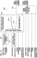
- FIG. 11 is a diagram similar to FIG. 4 and is a functional block diagram of a main controller 300 according to the third embodiment.
- a relief valve 72 is provided to regulate the maximum pressure of the bottom pressure Pa of the arm cylinder 4 to a preset relief pressure. If the bottom pressure Pa of the arm cylinder 4 rises to the relief pressure during the process in which the wheel loader 1 plunges into the excavation target 91 and the bucket 3 is penetrated into the excavation target 91, there is a risk that the raising operation of the arms 2 is not appropriately performed.
- the raising operation of the arms 2 is appropriately performed by deciding the distribution ratios ⁇ I and ⁇ C of the torque in consideration of the bottom pressure Pa of the arm cylinder 4.
- the torque distribution ratio calculation section 333 when the excavation determination flag is set to ON, calculates the distribution ratios ⁇ I and ⁇ C of the torque on the basis of the reaction force F R and the bottom pressure Pa of the arm cylinder 4.
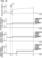
- FIG. 12 is a diagram similar to FIG. 6 and showing a torque distribution ratio table according to the third embodiment.
- a plurality of torque distribution ratio tables according to the magnitude of the bottom pressure Pa of the arm cylinder 4 are stored in the ROM 105 such that the distribution ratio ⁇ C of the travel driving torque changes according to the magnitude of the bottom pressure Pa of the arm cylinder 4.
- the main controller 300 selects a torque distribution ratio table corresponding to the magnitude of the bottom pressure Pa of the arm cylinder 4 and decides the distribution ratio ⁇ C of the travel driving torque on the basis of the reaction force F R .
- the torque distribution ratio table is set such that as the reaction force F R becomes larger, the distribution ratio ⁇ C of the travel driving torque becomes larger and as the bottom pressure Pa of the arm cylinder 4 becomes higher, the distribution ratio ⁇ C of the travel driving torque becomes smaller.
- the distribution ratio ⁇ C of the travel driving torque becomes large. Then, since the bottom pressure Pa of the arm cylinder 4 becomes large from the middle to the end of the penetration of the bucket 3 into the excavation target 91, the distribution ratio ⁇ C of the travel driving torque becomes small.
- the main controller 300 controls the travel driving torque such that as the pressure of the arm cylinder (hydraulic cylinder) 4 for operating the arms 2 becomes larger, the travel driving torque becomes smaller. Since the bottom pressure Pa of the arm cylinder 4 can be lowered by making the travel driving torque smaller as the bottom pressure Pa of the arm cylinder 4 becomes closer to the relief pressure, the lifting operation of the arms 2 can be appropriately performed.
- the method of deciding the distribution ratio ⁇ C of the travel driving torque by selecting a table according to the bottom pressure Pa of the arm cylinder 4 from among the plurality of torque distribution ratio tables has been described, but the method of deciding the distribution ratio ⁇ C is not limited to this.
- a reference distribution ratio is decided on the basis of the torque distribution ratio table described in the first embodiment, and the distribution ratio ⁇ C may be decided by multiplying the reference distribution ratio by a factor preset according to the bottom pressure Pa of the arm cylinder 4.
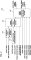
- FIG. 13 is a diagram similar to FIG. 4 and is a functional block diagram of a main controller 400 according to the fourth embodiment.
- the main controller 400 further has a function as a torque upper limit value calculation section 433 for deciding the upper limit value T I_LIM of the work driving torque and the upper limit value T C_LIM of the travel driving torque.
- the engine torque distribution calculation section 434 decides the work target torque T I_TGT on the basis of the work demanded torque T I_REQ and the work driving torque upper limit value T I_LIM decided by the torque upper limit value calculation section 433.
- the engine torque distribution calculation section 434 decides the travel target torque T C_TGT on the basis of the travel demanded torque T C_REC and the travel driving torque upper limit value T C_LIM decided by the torque upper limit value calculation section 433.
- the main controller 400 decides the upper limit value T I_LIM of the work driving torque and the upper limit value T C_LIM of the travel driving torque on the basis of the reaction force F R , and controls the work driving torque and the travel driving torque on the basis of the upper limit value T I_LIM of the work driving torque and the upper limit value T C_LIM of the travel driving torque. That is, the main controller 400 can change the distribution ratios of the work driving torque and the travel driving torque on the basis of the reaction force F R by controlling the work driving torque and the travel driving torque on the basis of the work driving torque upper limit value T I_LIM and the travel driving torque upper limit value T C_LIM .
- the work driving torque and the travel driving torque are controlled such that the distribution ratios of the work driving torque and the travel driving torque become close to proper distribution ratios. Accordingly, the work driving torque and the travel driving torque intended by the operator can be generated until the upper limit values are exceeded. For operators who feel such a configuration easier to handle, the work efficiency can be improved over the first embodiment.
- the travel demanded torque reaches the upper limit value of the travel driving torque when the operation amount of the accelerator pedal 58 is smaller than the maximum operation amount, or the work demanded torque reaches the upper limit value of the work driving torque when the operation amounts of the arm operation lever 52 and the bucket operation lever 53 are smaller than the maximum operation amounts. Therefore, it is possible to reduce the frequency at which the operator steps on the accelerator pedal 58 to maximize the operation amount of the accelerator pedal 58 or the operator tilts the arm operation lever 52 and the bucket operation lever 53 until the operation amounts of the arm operation lever 52 and the bucket operation lever 53 are maximized. As a result, the total operation amount by the operator can be decreased, and the burden on the operator can be reduced.
- FIG. 14 is a diagram similar to FIG. 4 and is a functional block diagram of a main controller 500 according to the fifth embodiment.
- the main controller 500 according to the fifth embodiment has, instead of the torque distribution ratio calculation section 133 of the main controller 100 according to the first embodiment, a function as a torque upper limit value calculation section 533 for deciding the upper limit value T I_LIM of the work driving torque and the upper limit value T C_LIM of the travel driving torque.
- the torque upper limit value calculation section 533 computes the torque upper limit values T I_LIM and T C_LIM on the basis of the reaction force F R .
- the torque upper limit value calculation section 533 refers to a preset upper limit value table, and computes the torque upper limit values T I_LIM and T C_LIM on the basis of the reaction force F R .
- the upper limit value table is defined in advance by experiments and the like and stored in the ROM 105.
- the upper limit value table of the travel driving torque is a table having characteristics in which as the reaction force F R becomes larger, the travel driving torque upper limit value T C_LIM becomes larger.
- the upper limit value table of the travel driving torque is set such that as the reaction force F R becomes larger, the ratio (inclination) of an increase in the travel driving torque upper limit value T C_LIM to an increase in the reaction force F R becomes smaller.
- the upper limit value table of the work driving torque is a table having characteristics in which as the reaction force F R becomes larger, the work driving torque upper limit value T I_LIM becomes smaller.
- the upper limit value table of the work driving torque is set such that as the reaction force F R becomes larger, the ratio (inclination) of an increase in the work driving torque upper limit value T I_LIM to an increase in the reaction force F R becomes larger.
- the engine torque distribution calculation section 534 decides the work target torque T I_TGT by using the above equation (5) on the basis of the work demanded torque T I_REQ and the work driving torque upper limit value T I_LIM decided by the torque upper limit value calculation section 533.
- the engine torque distribution calculation section 534 decides the travel target torque T C_TGT by using the above equation (6) on the basis of the travel demanded torque T C_REQ and the travel driving torque upper limit value T C_LIM decided by the torque upper limit value calculation section 533.
- the main controller 500 can change the distribution ratios of the work driving torque and the travel driving torque on the basis of the reaction force F R by controlling the work driving torque and the travel driving torque on the basis of the work driving torque upper limit value T I_LIM and the travel driving torque upper limit value T C_LIM . According to such a fifth embodiment, the working effects similar to the fourth embodiment can be obtained.
- the calculation method of the work driving torque command T I_COM and the travel driving torque command T C_COM is not limited to the method described in the above embodiments.
- the engine torque distribution calculation section 134 may calculate the work driving torque command T I_COM and the travel driving torque command T C_COM on the basis of the distribution ratios ⁇ C and ⁇ I calculated by the torque distribution ratio calculation section 133, the engine output power torque TE, the auxiliary machine demanded torque T AUX_REQ , the work demanded torque T I_REQ , and the travel demanded torque T C_REQ , as will be described below.
- the engine torque distribution calculation section 134 when the total demanded torque value T SUM_REQ is equal to or less than the engine output power torque TE, sets the work demanded torque T I_REC as the work target torque T I_TGT and the travel demanded torque T C_REC as the travel target torque T C_TGT .
- the engine torque distribution calculation section 134 calculates the work target torque T I_TGT and the travel target torque T C_TGT by subtracting a predetermined amount from the work demanded torque T I_REQ and the travel demanded torque T C_REQ in accordance with the torque distribution ratio ⁇ by the difference value ⁇ TE between the total demanded torque value T SUM_REQ and the engine output power torque TE.
- the engine torque distribution calculation section 134 makes the total target torque value T SUM_TGT , which is the sum of the auxiliary machine demanded torque T AUX_REQ , the work target torque T I_TGT , and the travel target torque T C_TGT , equal to the engine output power torque TE.
- the maximum values of the travel driving force and the work driving force are not reduced even when the excavation determination flag is set to ON. Therefore, the wheel loader 1 can be operated as more intended by the operator while improving the work efficiency. According to the modified example, the work efficiency can be improved as similar to the first embodiment, and the operability of the vehicle body can be further improved.
- the engine torque distribution calculation section 134 may calculate the work target torque T I_TGT by an equation (7) and the travel target torque T C_TGT by an equation (8) .
- T I _ TGT T I _ REQ ⁇ ⁇ I ⁇ k
- T C _ TGT T C _ REQ ⁇ ⁇ C ⁇ k
- k is a constant and stored in advance in the ROM 105.
- the work target torque T I_TGT becomes the value equal to or less than the work demanded torque T I_REQ
- the travel target torque T C_TGT becomes the value equal to or less than the travel demanded torque T C_REC .
- ⁇ I is 50% and ⁇ C is 50%
- the work target torque T I_TGT becomes the value half the work demanded torque T I_REQ
- the travel target torque T C_TGT becomes the value half the travel demanded torque T C_REC .
- the work target torque T I_TGT and the travel target torque T C_TGT can be made larger, and thus it is possible to be made closer to the work driving force and the travel driving force intended by the operator.
- k is set to 2
- the work target torque T I_TGT becomes the value of the work demanded torque T I_REQ
- the travel target torque T C_TGT becomes the value of the travel demanded torque T C_REC .
- the value of k may be optionally set by the operator by manual operation.
- the power generation inverter 41 and the travel inverter 42 may be power converters without via a DC section as represented by a matrix converter.
- the present invention is not limited to this.
- the present invention can also be applied to a wheel loader having a configuration in which the voltage of the DC section 44 is controlled or electric power is supplied by connecting a power storage device including a power storage element such as a secondary battery or a capacitor to the DC section 44.
- the present invention is not limited to this.
- the bottom pressure Pa of the arm cylinder 4 is proportional to the traction force F P . Therefore, the traction force F P may be calculated on the basis of the bottom pressure Pa of the arm cylinder 4 sensed by the pressure sensor 71.
- an acceleration sensor is attached to the wheel loader 1, and the traction force F P may be calculated on the basis of the acceleration sensed by the acceleration sensor and the mass of the wheel loader 1.
- the method of determining that the excavation work has been started is not limited to the method described in the above embodiments. For example, it may be determined that the excavation work has been started in consideration of the reaction force F R calculated by the reaction force calculation section 131.
- the excavation state determination section 132 determines that the excavation work has been started when the bucket 3 is within the angle range indicating that the bucket 3 is in the plunging posture, the bottom pressure Pa of the arm cylinder 4 is equal to or more than the pressure threshold value Pa0, and the reaction force F R is equal to or more than a predetermined reaction force threshold value. Accordingly, it is possible to reduce the occurrence of erroneous determination in which it is determined as the excavation state when the excavation work is not being performed.
- the present invention is not limited to this.
- the time threshold value is stored in advance in the ROM 105.
- the time threshold value is defined in advance by experiments and the like.
- the main controller 100 decides the distribution ratio ⁇ I of the work driving torque and the distribution ratio ⁇ C of the travel driving torque on the basis of the reference values ⁇ I 0 and ⁇ C 0 in Step S160, and decides the distribution ratio ⁇ I of the work driving torque and the distribution ratio ⁇ C of the travel driving torque on the basis of the setting values ⁇ IS and ⁇ CS set by the torque distribution ratio setting dial 54 in Step S170 has been described.
- Step S160 the main controller 100 may decide the distribution ratio ⁇ I of the work driving torque and the distribution ratio ⁇ C of the travel driving torque on the basis of the setting values ⁇ IS and n CS set by the torque distribution ratio setting dial 54.
- Step S170 the main controller 100 may decide the distribution ratio ⁇ I of the work driving torque and the distribution ratio ⁇ C of the travel driving torque on the basis of the reference values ⁇ I 0 and ⁇ C 0. It should be noted that in both Steps S160 and S170, in a case where the distribution ratios ⁇ I and ⁇ C are decided on the basis of the reference values ⁇ I 0 and ⁇ C 0, the torque distribution ratio setting dial 54 can be omitted.
- the main controllers 100, 300, 400, and 500 calculate the reaction force F R acting on the vehicle body 8 of the wheel loader 1 and decides the torque distribution ratio and the torque upper limit value on the basis of the calculated reaction force F R has been described, but the present invention is not limited to this.
- the main controllers may calculate the physical quantity correlated with the reaction force F R acting on the wheel loader 1 and decide the torque distribution ratio and the torque upper limit value on the basis of the calculated physical quantity.
- the physical quantity correlated with the reaction force F R for example, the bottom pressure Pa of the arm cylinder 4 can be used.
- the main controllers control the work driving torque and the travel driving torque on the basis of the reaction force received by the vehicle body 8 of the wheel loader 1. Accordingly, it is possible to set the torque distribution ratio during the excavation work on a work site where the ground is inclined from the horizontal plane in the same manner as the torque distribution ratio during the excavation work on a work site where the ground is parallel to the horizontal plane. That is, the effect of the inclination of the ground can be reduced.
- the calculation method of the reaction force F R is not limited to this.
- the time change ratio of the vehicle velocity v at the beginning of penetration into the excavation target 91 is compared with the time change ratio of the vehicle velocity v stored in advance in the ROM 105, and when the both match each other, the reaction force F R may be decided from a reaction force calculation data table stored in the ROM 105.
- the reaction force calculation data table is defined in advance for each time change ratio of a plurality of vehicle velocities v (that is, for each of a plurality of vehicle velocity change patterns) by experiments and the like.
- the values used for various determinations and calculations may be subjected to moving average processing or low-pass filter processing in order to avoid the effects of disturbance and noise.
- Some or all of the functions of the main controllers described in the above embodiments may be realized by hardware (for example, by designing the logic to execute each function using an integrated circuit).
Landscapes
- Engineering & Computer Science (AREA)
- General Engineering & Computer Science (AREA)
- Mechanical Engineering (AREA)
- Structural Engineering (AREA)
- Mining & Mineral Resources (AREA)
- Civil Engineering (AREA)
- Fluid Mechanics (AREA)
- Physics & Mathematics (AREA)
- Transportation (AREA)
- Chemical & Material Sciences (AREA)
- Combustion & Propulsion (AREA)
- Automation & Control Theory (AREA)
- Operation Control Of Excavators (AREA)
- Control Of Fluid Gearings (AREA)
- Hybrid Electric Vehicles (AREA)
- Electric Propulsion And Braking For Vehicles (AREA)
Abstract
Description
- The present invention relates to a work vehicle.
- A work vehicle including a travel device for moving a vehicle body and a work device having a bucket and arms for excavating sediment and the like has been known. Such a work vehicle performs excavation work by distributing the power of an engine to the travel device and the work device. At this time, if the travel driving force is large and the work driving force is too small, it becomes difficult to lift the bucket, and the work efficiency is reduced. On the other hand, if the travel driving force is small and the work driving force is too large, the work efficiency is reduced because the bucket cannot be sufficiently penetrated into the sediment or the bucket is lifted before the sediment is sufficiently put in the bucket.
-
Patent Document 1 discloses a method for automatically setting, on the basis of an average bucket weight after excavation work, the distribution ratios (characteristics P, N, and L) of the travel driving force and the work driving force during the subsequent excavation work. - Patent Document 1:
JP-2012-233521-A - According to the technique described in
Patent Document 1, in a case where the excavation work is repeatedly performed, the present excavation work is performed on the basis of the distribution ratios of the travel driving force and the work driving force set on the basis of the average bucket weight after the previous excavation work. Thus, in a case where the hardness of an excavation target targeted for the present excavation work is different from the hardness of an excavation target targeted for the previous excavation work, there is a risk that the set distribution ratios deviate from the ranges of the distribution ratios suitable for the excavation of the present excavation target, and the efficiency of the excavation work is reduced. - An object of the present invention is to improve the efficiency of excavation work.
- A work vehicle according to an aspect of the present invention includes: an engine that is mounted on a vehicle body; a hydraulic pump that is driven by the engine; hydraulic cylinders that are extended and contracted by pressurized fluid delivered from the hydraulic pump; a work device that is moved according to the extension/contraction operations of the hydraulic cylinders; a travel device that is driven independently of the work device; an electrically driven motor that is driven by electric power generated by the engine to operate the travel device; and a controller that controls the hydraulic cylinders and the electrically driven motor. The controller controls output power of the hydraulic pump and output power of the electrically driven motor by changing distribution ratios of a first torque consumed by the work device and a second torque consumed by the travel device among torques output by the engine, on the basis of a reaction force received by the vehicle body.
- According to the present invention, the efficiency of excavation work can be improved.
-
-
FIG. 1 is a side view of a wheel loader. -
FIG. 2 is a system configuration diagram of the wheel loader. -
FIG. 3 is diagrams for explaining the basic excavation work of the wheel loader. -
FIG. 4 is a functional block diagram of a main controller according to a first embodiment. -
FIG. 5 is a diagram for explaining a bucket angle θ. -
FIG. 6 is a diagram for showing a torque distribution ratio table according to the first embodiment. -
FIG. 7A is a diagram for showing an example of a pump demanded map used to calculate a pump demanded flow rate. -
FIG. 7B is a diagram for showing an example of a torque map of a travel motor used to calculate a travel demanded torque. -
FIG. 8 is a flowchart for showing the content of a torque decision process executed by the main controller. -
FIG. 9 is time charts for showing the operation of the main controller according to the first embodiment. -
FIG. 10 is time charts for showing the operation of a main controller according to a second embodiment. -
FIG. 11 is a functional block diagram of a main controller according to a third embodiment. -
FIG. 12 is a diagram for showing a torque distribution ratio table according to the third embodiment. -
FIG. 13 is a functional block diagram of a main controller according to a fourth embodiment. -
FIG. 14 is a functional block diagram of a main controller according to a fifth embodiment. - Hereinafter, embodiments of the present invention will be described with reference to the drawings. It should be noted that an example in which a work vehicle is an electrically-driven wheel loader will be described in the embodiments.
- A work vehicle according to a first embodiment of the present invention will be described with reference to
FIG. 1 to FIG. 9 .FIG. 1 is a side view of a wheel loader. As shown inFIG. 1 , awheel loader 1 includes a vehicle body 8 mounted with atravel device 11 and an articulatedwork device 6 attached to the front of the vehicle body 8. The vehicle body 8 is an articulated steering type (vehicle body bending type) vehicle body and has afront vehicle body 8A, arear vehicle body 8B, and acenter joint 10 coupling thefront vehicle body 8A and therear vehicle body 8B to each other. - On the
rear vehicle body 8B, anoperation room 12 and anengine room 16 are mounted in the front and the rear, respectively. An engine 20 (seeFIG. 2 ),hydraulic pumps FIG. 2 ) driven by theengine 20, and hydraulic equipment such as valves are mounted in theengine room 16. -
FIG. 2 is a system configuration diagram of thewheel loader 1. As shown inFIG. 2 , thewheel loader 1 includes theengine 20, apower generation motor 40 mechanically connected to theengine 20, thehydraulic pumps engine 20, thework device 6 driven by a hydraulic operating fluid delivered from thehydraulic pump 30A, a frontdevice control section 31 controlling the operation of thework device 6, abrake device 21 driven by a hydraulic operating fluid delivered from thehydraulic pump 30B, abrake control section 32 controlling the operation of thebrake device 21, a steering device 22 driven by a hydraulic operating fluid delivered from thehydraulic pump 30C, asteering control section 33 controlling the steering device 22, and thetravel device 11 driven by the electric power generated by thepower generation motor 40. - The
work device 6 and thetravel device 11 are driven independently of each other by the power of theengine 20. Theengine 20 is configured using, for example, an internal combustion engine such as a diesel engine. - As shown in
FIG. 1 , thework device 6 is attached to thefront vehicle body 8A. Thework device 6 has lift arms (hereafter, simply referred to as arms) 2 rotatably attached to thefront vehicle body 8A and abucket 3 rotatably attached to thearms 2. Thearms 2 are moved according to the extension/contraction operation ofarm cylinders 4, which are hydraulic cylinders, and thebucket 3 is moved according to the extension/contraction operation of abucket cylinder 5, which is a hydraulic cylinder. It should be noted that onearm 2 and onearm cylinder 4 are provided on each of the left and right of thefront vehicle body 8A. In addition, in the embodiment, a Z-link type (bell crank type) link mechanism is employed as a link mechanism for operating thebucket 3. - The
hydraulic cylinders hydraulic pump 30A that is rotated by the torque output by the engine 20 (seeFIG. 2 ). - The
travel device 11 hasfront wheels 7A (tires 7) attached to thefront vehicle body 8A,rear wheels 7B (tires 7) attached to therear vehicle body 8B, and a power transmission device that transmits power from thetravel motor 43 to thetires 7. The power transmission device includes an axle, a differential device, a propeller shaft, and the like. - The
travel motor 43 is an electrically driven motor that is rotationally driven by the electric power generated by thepower generation motor 40 rotated by the torque output from theengine 20 and operates thetravel device 11. It should be noted that thewheel loader 1 is turned by the steering device 22 having a pair of left and right hydraulic cylinders (hereafter, referred to as steering cylinders) 15 provided so as to couple thefront vehicle body 8A and therear vehicle body 8B to each other. - As shown in
FIG. 2 , thehydraulic pumps engine 20 and thepower generation motor 40. Thehydraulic pumps engine 20 to deliver the hydraulic operating fluids as working fluids. It should be noted that in a case where thepower generation motor 40 functions as an electric motor, thehydraulic pumps engine 20 and thepower generation motor 40. - The pressure, flow rate, and flow direction of the hydraulic operating fluid delivered from the
hydraulic pump 30A are controlled by the frontdevice control section 31. The pressure, flow rate, and flow direction of the hydraulic operating fluid delivered from thehydraulic pump 30B are controlled by thebrake control section 32. The pressure, flow rate, and flow direction of the hydraulic operating fluid delivered from thehydraulic pump 30C are controlled by thesteering control section 33. - The
wheel loader 1 includes amain controller 100 that is a controller for controlling thehydraulic cylinders work device 6 and thetravel motor 43 for operating thetravel device 11, a power generation inverter (inverter for the power generation motor) 41 that controls thepower generation motor 40 on the basis of a power generation voltage command input from themain controller 100, a travel inverter (inverter for the travel motor) 42 that controls the torque of thetravel motor 43 on the basis of a travel driving torque command input from themain controller 100, and various operation members (50 to 59) provided in theoperation room 12. - In the
operation room 12, provided are anarm operation lever 52 for driving thearms 2, a bucket operation lever 53 for driving thebucket 3, a forward/backward switch 51 that is a forward/backward switching device for switching the forward (F) and backward (R) of the vehicle body 8, anaccelerator pedal 58 for accelerating the vehicle body 8, abrake pedal 59 for decelerating the vehicle body 8, asteering wheel 55 for instruction on the left/right advancing direction of the vehicle body 8, a mode switching switch 57 that is a switching device for switching a torque distribution mode to either a MANUAL mode or an AUTO mode, a torque distribution ratio setting dial 54 for manually setting the ratio at which the output torque of theengine 20 is distributed to thework device 6 and thetravel device 11, and aparking brake switch 56 for operating the parking brake. - The
main controller 100 is configured using a microcomputer including a CPU (Central Processing Unit) 104 as an operating circuit, a ROM (Read Only Memory) 105 and a RAM (Random Access Memory) 106 as storage devices, aninput interface 107, anoutput interface 108, and other peripheral circuits. It should be noted that themain controller 100 may be configured using one microcomputer or a plurality of microcomputers. - The
ROM 105 of themain controller 100 is a nonvolatile memory such as an EEPROM and stores programs that can execute various computations. That is, theROM 105 of themain controller 100 is a storage medium that can read programs for realizing the functions of the embodiment. TheRAM 106 is a volatile memory and a work memory that directly inputs and outputs data with theCPU 104. TheRAM 106 temporarily stores necessary data while theCPU 104 computes and executes a program. It should be noted that themain controller 100 may further include a storage device such as a flash memory or a hard disk drive. - The
CPU 104 is a processing device that expands the program stored in theROM 105 into theRAM 106 to execute computations, and performs a predetermined computation process for signals taken from theinput interface 107, theROM 105, and theRAM 106 according to the program. - An operation signal and a sensor signal are input to the
input interface 107. Theinput interface 107 converts the input signal such that theCPU 104 can compute. Theoutput interface 108 generates a signal for output according to the computation result in theCPU 104, and outputs the signal to the frontdevice control section 31, thebrake control section 32, thesteering control section 33, thepower generation inverter 41, thetravel inverter 42, and the like. - The
main controller 100 comprehensively controls the frontdevice control section 31, thebrake control section 32, thesteering control section 33, thepower generation inverter 41, and thetravel inverter 42 on the basis of the operation signals input by an operator's operation and the sensor signals sensed by various sensors. - The operation signals input to the
main controller 100 include an accelerator signal output from theaccelerator pedal 58 and indicating the operation amount of theaccelerator pedal 58, a brake signal output from thebrake pedal 59 and indicating the operation amount of thebrake pedal 59, an arm signal output from thearm operation lever 52 and indicating the operation amount of thearm operation lever 52, a bucket signal output from the bucket operation lever 53 and indicating the operation amount of the bucket operation lever 53, a steering signal output from thesteering wheel 55 and indicating the operation amount of thesteering wheel 55, an advancing direction signal output from the forward/backward switch 51 and indicating the operation position of the forward/backward switch 51, and the like. In addition, the operation signals input to themain controller 100 include a mode switching signal output from the mode switching switch 57 and indicating the operation position of the mode switching switch 57, and a ratio setting signal output from the torque distribution ratio setting dial 54 and indicating the operation position of the torque distribution ratio setting dial 54. - The sensor signals input to the
main controller 100 include a signal indicating the angle sensed by an armrelative angle sensor 62 provided on a coupling shaft coupling the vehicle body 8 and thearms 2 to each other, and a signal indicating the angle sensed by a bucketrelative angle sensor 63 provided on a coupling shaft coupling thearms 2 and thebucket 3 to each other. The armrelative angle sensor 62 is a potentiometer that senses the relative angle (inclined angle) of thearms 2 to the vehicle body 8 and outputs a signal indicating the sensed angle to themain controller 100. The bucketrelative angle sensor 63 is a potentiometer that senses the relative angle (inclined angle) of thebucket 3 to thearms 2 and outputs a signal indicating the sensed angle to themain controller 100. Since the angle of the vehicle body 8 relative to the ground (travel surface) is constant, the angle sensed by the armrelative angle sensor 62 can be said to correspond to the relative angle (inclined angle) of thearms 2 to the ground. - In addition, the sensor signals input to the
main controller 100 include a signal indicating the vehicle velocity sensed by a vehicle velocity sensor 61. The vehicle velocity sensor 61 senses the vehicle velocity (travel velocity) of thewheel loader 1 and outputs a signal indicating the sensed vehicle velocity to themain controller 100. Further, the sensor signals input to themain controller 100 include signals indicating the revolution speeds of theengine 20, thepower generation motor 40, thehydraulic pumps travel motor 43 sensed by a plurality of revolution speed sensors, and signals indicating the delivery pressures of thehydraulic pumps - The
main controller 100 outputs a front device control command on the basis of the operation directions and the operation amounts of the operation levers 52 and 53. The frontdevice control section 31, on the basis of the front device control command from themain controller 100, adjusts the pressure, velocity, and direction of the hydraulic operating fluid delivered from thehydraulic pump 30A to operate thearm cylinders 4 and thebucket cylinder 5. The frontdevice control section 31 has a direction control valve for controlling the flow of the hydraulic operating fluid delivered from thehydraulic pump 30A, a solenoid valve for generating a pilot pressure input into the pilot chamber of the direction control valve, and the like. - The
main controller 100 outputs a brake control command on the basis of the operation amount of thebrake pedal 59 and the operation position of theparking brake switch 56. Thebrake control section 32, on the basis of the brake control command from themain controller 100, adjusts the pressure, velocity, and direction of the hydraulic operating fluid delivered from thehydraulic pump 30B to operatehydraulic cylinders brake control section 32 has a direction control valve for controlling the flow of the hydraulic operating fluid delivered from thehydraulic pump 30B, a solenoid valve for generating a pilot pressure input into the pilot chamber of the direction control valve, and the like. - The
main controller 100 outputs a steering control command on the basis of the operation direction and the operation amount of thesteering wheel 55. Thesteering control section 33, on the basis of the steering control command from themain controller 100, adjusts the pressure, velocity, and direction of the hydraulic operating fluid delivered from thehydraulic pump 30C to operate thesteering cylinders 15. Thesteering control section 33 has a direction control valve for controlling the flow of the hydraulic operating fluid delivered from thehydraulic pump 30C, a solenoid valve for generating a pilot pressure input into the pilot chamber of the direction control valve, and the like. - As described above, in the embodiment, the
hydraulic pumps engine 20, and thework device 6, thebrake device 21, and the steering device 22 are driven by the hydraulic operating fluids delivered from thehydraulic pumps - The
power generation inverter 41 and thetravel inverter 42 are connected to each other via a DC section (DC bus) 44. It should be noted that thewheel loader 1 according to the embodiment does not include a power storage device connected to theDC section 44. Thepower generation inverter 41, on the basis of a power generation voltage command from themain controller 100, controls the bus voltage of theDC section 44 by using the electric power supplied from thepower generation motor 40. Thetravel inverter 42, on the basis of the travel driving torque command of themain controller 100, drives thetravel motor 43 by using the electric power of theDC section 44. - As described above, in the embodiment, the
power generation motor 40 is driven by the torque output from theengine 20, and thetravel motor 43 is driven by the electric power generated by thepower generation motor 40. - When the
arm operation lever 52 is operated, thearms 2 are rotated (moved up and down) in the up and down directions by the extension/contraction operation of thearm cylinders 4. When the bucket operation lever 53 is operated, thebucket 3 is rotated (crowding operation or dump operation) in the up and down directions by the extension/contraction operation of thebucket cylinder 5. - When the
steering wheel 55 is operated, thefront vehicle body 8A is refracted (turned) left and right with the center joint 10 in the center against therear vehicle body 8B, according to the extension/contraction operation of the steering cylinders 53. Thetires 7 are rotated by the driving of thetravel motor 43 to move thewheel loader 1 forward and backward. - When the
accelerator pedal 58 is stepped on in a state where the forward/backward switch 51 is operated to the forward side, thetires 7 rotate in the forward direction and the vehicle body 8 travels forward. When theaccelerator pedal 58 is stepped on in a state where the forward/backward switch 51 is operated to the backward side, thetires 7 rotate in the backward direction and the vehicle body 8 travels backward. - The mode switching switch 57 is a mode switch operation section that can be manually switched between an AUTO mode (first control mode) in which the work driving torque and the travel driving torque are controlled on the basis of a reaction force FR acting on the vehicle body 8 of the
wheel loader 1 and a MANUAL mode (second control mode) in which the work driving torque and the travel driving torque are controlled such that the ratios of the work driving torque and the travel driving torque are held at predetermined ratios regardless of the reaction force FR. - It should be noted that the work driving torque corresponds to the torque (first torque) consumed by the
work device 6 among those output from theengine 20. That is, in the embodiment, the work driving torque corresponds to the input torque of thehydraulic pump 30A. The travel driving torque corresponds to the torque (second torque) consumed by thetravel device 11 among those output from theengine 20. That is, in the embodiment, the travel driving torque corresponds to the output torque of thetravel motor 43. - The mode switching switch 57 has an AUTO mode position and a MANUAL mode position. Where the mode switching switch 57 is operated to the AUTO mode position, a signal indicating that the AUTO mode is selected is output to the
main controller 100. In this case, themain controller 100 sets the AUTO mode as the torque distribution mode. Where the mode switching switch 57 is operated to the MANUAL mode position, a signal indicating that the MANUAL mode is selected is output to themain controller 100. In this case, themain controller 100 sets the MANUAL mode as the torque distribution mode. - The torque distribution ratio setting dial 54 is an operation member for setting a setting value ηCS of the torque distribution ratio used when the torque distribution mode is set to the MANUAL mode. The
main controller 100, on the basis of the operation position of the torque distribution ratio setting dial 54, sets the setting value ηCS of the distribution ratio of the travel driving torque. Further, themain controller 100 sets a setting value ηIS of the distribution ratio of the work driving torque. Themain controller 100 subtracts the setting value ηCS[%] of the distribution ratio of the travel driving torque from 100[%] to calculate the setting value ηIS of the distribution ratio of the work driving torque (100 - ηCS = ηIS[%]). Themain controller 100 stores the setting values ηCS and ηIS of the torque distribution ratios in theROM 105. - Next, the basic excavation work of the
wheel loader 1 will be described with reference toFIGs. 3 . In the excavation work of thewheel loader 1, thewheel loader 1 is first advanced toward anexcavation target 91 such as a sediment pile or a natural ground as shown inFIG. 3(a) . Next, as shown inFIG. 3(b) , thebucket 3 is penetrated into theexcavation target 91 in such a manner as to plunge into theexcavation target 91, and thearms 2 and thebucket 3 are operated to put objects to be carried such as sediment into thebucket 3. Finally, as shown inFIG. 3(c) , the excavation work is completed by scooping up (performing the crowding operation) thebucket 3 toward the operator so as not to spill the objects to be carried such as sediment put in thebucket 3. After the excavation work is completed, thewheel loader 1 is moved backward once and advanced toward a conveying vehicle such as a dump truck. At this time, the operator operates thesteering wheel 55 to advance thewheel loader 1 toward the dump truck while raising thearms 2 by operating thearm operation lever 52. After stopping thewheel loader 1 in front of the dump truck, the operator loads the objects to be carried in thebucket 3 onto the cargo bed of the dump truck (that is, releases the sediment in the bucket 3) by operating the bucket operation lever 53 to allow thebucket 3 to perform the dump operation. When the loading work is completed, the operator moves thewheel loader 1 backward again and returns to the original position. - A series of work including the excavation work and the loading work accounts for the majority of the whole work time of the
wheel loader 1. Therefore, in order to improve the work efficiency of thewheel loader 1, it is effective to improve the efficiency of the series of work. It should be noted that the work efficiency corresponds to, for example, the weight [ton/h] of the excavated material loaded onto the conveying vehicle per unit time in the series of work including the excavation work and the loading work, and a larger weight means that a more amount of materials can be excavated in a shorter time. - Here, if the balance between the driving force (travel driving force) of the
travel device 11 and the driving force (work driving force) of thework device 6 is poor, the efficiency of the excavation work is reduced. For example, where the travel driving force is insufficient and the work driving force is excessive, the work efficiency is reduced because thebucket 3 cannot be sufficiently penetrated into theexcavation target 91 or thebucket 3 is lifted above theexcavation target 91 before the sediment is sufficiently put in thebucket 3. On the other hand, where the work driving force is insufficient and the travel driving force is excessive, the work efficiency is reduced because it takes time to lift thebucket 3. As described above, if the balance between the travel driving force and the work driving force is poor, the work efficiency is reduced. - Accordingly, in the embodiment, the efficiency of the excavation work in the series of work is improved by appropriately balancing the driving force (travel driving force) of the
travel device 11 required to appropriately penetrate thebucket 3 into theexcavation target 91 and the driving force (work driving force) of thework device 6 required to load a large amount of sediment into thebucket 3 in a short time. - It should be noted that the appropriate balance between the travel driving force and the work driving force changes depending on the hardness of the
excavation target 91. As the hardness of theexcavation target 91 is greater, a larger travel driving force is required. The influence of the hardness of theexcavation target 91 appears in the reaction force received by the vehicle body 8 of thewheel loader 1 from theexcavation target 91 during the excavation work. The reaction force acting on the vehicle body 8 of thewheel loader 1 becomes larger as the hardness of theexcavation target 91 is greater. In the embodiment, the work efficiency is improved by adjusting the balance between the travel driving force and the work driving force on the basis of the reaction force acting on the vehicle body 8 of thewheel loader 1 during the excavation work. -
FIG. 4 is a functional block diagram of themain controller 100. As shown inFIG. 4 , themain controller 100, by executing the programs stored in theROM 105, functions as a reactionforce calculation section 131 that calculates the reaction force FR received by the vehicle body 8 of thewheel loader 1, an excavationstate determination section 132 that determines whether or not thewheel loader 1 is in the state of performing the excavation work, a torque distributionratio calculation section 133 that decides the distribution ratios nI and ηC of the work driving torque and the travel driving torque on the basis of the reaction force FR calculated by the reactionforce calculation section 131, and an engine torquedistribution calculation section 134 that decides a work driving torque command for controlling the work driving torque and a travel driving torque command for controlling the travel driving torque on the basis of the distribution ratios ηI and ηC decided by the torque distributionratio calculation section 133. - The reaction
force calculation section 131, on the basis of the traction force FP and the vehicle velocity v of thewheel loader 1, calculates the reaction force FR received by the vehicle body 8 of thewheel loader 1. An example of a method for calculating the reaction force FR will be described. The reaction force FR is obtained by the following equation (1) using a relation between momentum and an impulse.
[Equation 1]
- Here, m is the mass of the
wheel loader 1, t0 is a reference time, t1 is a time after a predetermined time elapses from the reference time t0, v0 is the vehicle velocity of thewheel loader 1 at the reference time t0, and v1 is the vehicle velocity of thewheel loader 1 at the time t1. It should be noted that although the vehicle velocity of thewheel loader 1 is sensed by the vehicle velocity sensor 61 in the embodiment, a rotary encoder that senses the revolution speed of a shaft configuring the power transmission device may be provided to compute the vehicle velocity on the basis of information sensed by the rotary encoder. - The traction force FP correlated with the travel driving force generated by the
travel motor 43 and is obtained by the following equation (2) on the basis of, for example, the output torque (travel driving torque) Tm of thetravel motor 43 at the time t1, a general reduction ratio λ, and the diameter Dt of thetire 7.
[Equation 2]
- It should be noted that the general reduction ratio λ is the ratio of the revolution speed of the
engine 20 to the revolution speed of thetires 7, and where a transmission is provided, it is calculated by multiplying the gear ratio of the transmission by the reduction ratio (differential ratio). In the equation, c is a factor for unit conversion. The travel driving torque (motor output torque) Tm may be sensed by a torque sensor or computed from the motor current sensed by a current sensor. - The reaction force FR calculated during the excavation work is dominated by the repulsive force acting on the
wheel loader 1 from theexcavation target 91 and is affected by the hardness of theexcavation target 91. The reference time t0 is the time when thewheel loader 1 plunged into the excavation target 91 (the time when thebucket 3 started penetrating the excavation target 91). - The
main controller 100 determines whether or not thewheel loader 1 has plunged into the excavation target 91 (that is, whether or not thebucket 3 has started penetrating the excavation target 91) on the basis of the operation amount of theaccelerator pedal 58 and the time change ratio of the vehicle velocity v of thewheel loader 1. When themain controller 100 determines that thewheel loader 1 has plunged into theexcavation target 91, a plunge flag is set to ON. In addition, themain controller 100 sets the time when the plunge flag has been set to ON as the reference time t0. It should be noted that the plunge flag is set to OFF when an excavation determination flag to be described later is set to OFF. - The
main controller 100 calculates the time change ratio D (= (vb - va)/(tb - ta)) of the vehicle velocity v by dividing a difference (vb - va) between the previous value va and the current value vb of the vehicle velocity v, which is repeatedly sensed in a predetermined control cycle, by a time Δt (= tb - ta) from a time ta when the previous value va has been sensed to a time tb when the current value vb has been sensed. When the operation amount of theaccelerator pedal 58 is equal to or more than a predetermined threshold value and the time change ratio D of the vehicle velocity v is equal to or more than a predetermined threshold value, themain controller 100 determines that thewheel loader 1 has plunged into theexcavation target 91. When the operation amount of theaccelerator pedal 58 is less than the predetermined threshold value or when the time change ratio D of the vehicle velocity v is less than the predetermined threshold value, themain controller 100 determines that thewheel loader 1 has not plunged into theexcavation target 91. - The excavation
state determination section 132 determines, on the basis of the angle (hereinafter, also referred to as a bucket angle) θ of thebucket 3 and the pressure (hereinafter, also referred to as a bottom pressure) Pa of the bottom-side hydraulic fluid chamber of thearm cylinder 4, whether or not thewheel loader 1 is in the state of performing the excavation work. The bottom pressure Pa of thearm cylinder 4 is sensed by a pressure sensor 71 provided in a hydraulic fluid line connecting the bottom-side hydraulic fluid chamber (not shown) of thearm cylinder 4 and the frontdevice control section 31 to each other as shown inFIG. 2 . The pressure sensor 71 outputs a sensed signal to themain controller 100. -
FIG. 5 is a diagram for explaining the bucket angle θ. As shown inFIG. 5 , the bucket angle θ is the inclined angle of thebucket 3 from areference surface 90. In the embodiment, thereference surface 90 is a surface set parallel to the ground (travel surface). In a state where the bottom surface of ablade section 39 of thebucket 3 is parallel to thereference surface 90, the bucket angle θ is 0[°]. When thebucket 3 is rotated by the crowding operation, the bucket angle θ increases with the rotation. In other words, when thebucket 3 is rotated by the dump operation, the bucket angle θ decreases with the rotation. The bucket angle θ is calculated by themain controller 100 on the basis of the relative angle of thearms 2 to thereference surface 90 sensed by the armrelative angle sensor 62 and the relative angle of thebucket 3 to thearms 2 sensed by the bucketrelative angle sensor 63. - The excavation
state determination section 132, when the bucket angle θ is within a preset angle range (a lower threshold value θa to an upper threshold value θb) and the bottom pressure Pa of thearm cylinder 4 is equal to or more than a preset pressure threshold value Pa0, determines that the excavation work has been started and sets the excavation determination flag to ON. The excavation determination flag is set to ON when thewheel loader 1 is in the state of performing the excavation work and is set to OFF when the excavation work is finished. - The lower threshold value θa and the upper threshold value θb defining the angle range are set on the basis of the plunging posture of the
work device 6. The plunging posture of thework device 6 is a posture in which thebucket 3 is approximately parallel to the travel surface (ground) in the vicinity of the travel surface (ground). The lower threshold value θa and the upper threshold value θb are stored in advance in theROM 105. - The bottom pressure Pa of the
arm cylinder 4 rises due to the plunging of thewheel loader 1 into theexcavation target 91. The pressure threshold value Pa0 is stored in advance in theROM 105. As the pressure threshold value Pa0, it is possible to employ, for example, a value about twice the bottom pressure of thearm cylinder 4 supporting thework device 6 whosebucket 3 is empty and which is in the plunging posture. - That is, the excavation
state determination section 132 determines that the excavation work has been started when the plunging of thewheel loader 1 into theexcavation target 91 is sensed by the rise of the arm cylinder pressure in a state where thework device 6 is in the plunging posture. - The excavation
state determination section 132, after it is determined that the excavation work has been started, determines that the excavation work has been finished and sets the excavation determination flag to OFF when the bucket angle θ becomes an angle threshold value θe (for example, about 30°) or more. It should be noted that themain controller 100 also sets the plunge flag to OFF when the excavation determination flag is set to OFF. The angle threshold value θe is a threshold value for determining whether or not the excavation work has been finished, and it is possible to employ, for example, the bucket angle θ when the crowding operation of thebucket 3 is completed and in a state where thebucket 3 is in the conveyance posture. That is, the excavationstate determination section 132 determines that the excavation work has been finished when sensing thebucket 3 in the conveyance posture after it is determined that the excavation work has been started. - The torque distribution
ratio calculation section 133 calculates the distribution ratio ηI[%] of the work driving torque and the distribution ratio ηC[%] of the travel driving torque on the basis of the reaction force FR calculated by the reactionforce calculation section 131, the excavation determination flag set by the excavationstate determination section 132, and the torque distribution mode. The distribution ratio ηI of the work driving torque takes a value of 0 to 100%. Similarly, the distribution ratio ηC of the travel driving torque takes a value of 0 to 100%. The sum of the distribution ratio nI of the work driving torque and the distribution ratio ηC of the travel driving torque is 100[%]. - The torque distribution
ratio calculation section 133, when the AUTO mode is set as the torque distribution mode, sets the distribution ratios ηI and ηC on the basis of the reaction force FR calculated by the reactionforce calculation section 131. -
FIG. 6 is a diagram for showing a torque distribution ratio table for deciding the distribution ratio ηC of the travel driving torque and the distribution ratio nI of the work driving torque. As shown by the solid line inFIG. 6 , the torque distribution ratio table is a table in which the reaction force FR received by the vehicle body 8 of thewheel loader 1 is associated with the distribution ratio ηC of the travel driving torque. It should be noted that the distribution ratio ηI of the work driving torque is indicated by the broken line inFIG. 6 . - The torque distribution ratio table shown in
FIG. 6 is stored in advance in theROM 105 of themain controller 100. As shown by the solid line inFIG. 6 , the torque distribution ratio table is a table having characteristics in which as the reaction force FR becomes larger, the distribution ratio ηC of the travel driving torque becomes larger. In addition, the torque distribution ratio table is set such that as the reaction force FR becomes larger, the ratio (inclination) of an increase in the distribution ratio ηC to an increase in the reaction force FR becomes smaller. Accordingly, the travel driving force can be quickly increased according to an increase in the reaction force FR when thewheel loader 1 is plunged into theexcavation target 91. The torque distribution ratio table is defined in advance by experiments and the like. - The torque distribution
ratio calculation section 133, when the excavation determination flag is set to ON, refers to the distribution ratio table of the travel driving torque shown by the solid line inFIG. 6 and calculates the distribution ratio ηC of the travel driving torque on the basis of the reaction force FR calculated by the reactionforce calculation section 131. In addition, the torque distributionratio calculation section 133 subtracts the distribution ratio ηC[%] of the travel driving torque from 100[%] to calculate the distribution ratio nI of the work driving torque (100 - ηC = ηI[%]). Since the distribution ratio ηC of the travel driving torque becomes larger as the reaction force FR becomes larger, the distribution ratio ηI of the work driving torque becomes smaller as the reaction force FR becomes larger. - Therefore, when the AUTO mode is set as the torque distribution mode, the distribution ratios ηC and nI change in real time according to the change in the reaction force FR while the
wheel loader 1 is performing the excavation work. - The torque distribution
ratio calculation section 133, when the MANUAL mode is set as the torque distribution mode, sets setting values ηCS and ηIS of the distribution ratios stored in theROM 105 as the distribution ratios ηC and ηI (ηC = ηCS and ηI = ηIS). That is, when the MANUAL mode is set, the distribution ratios ηC and ηI are held at constant values even if the reaction force FR changes. - The engine torque
distribution calculation section 134 calculates a work driving torque command TI_COM and a travel driving torque command TC_COM on the basis of the distribution ratios ηC and ηI calculated by the torque distributionratio calculation section 133, an engine output power torque TE, an auxiliary machine demanded torque TAUX_REQ, a work demanded torque TI_REQ, and a travel demanded torque TC_REQ. - The engine output power torque TE, the auxiliary machine demanded torque TAUX_REQ, the work demanded torque TI_REQ, and the travel demanded torque TC_REQ are calculated by the
main controller 100. The engine output power torque TE is the maximum torque that can be output at the current engine revolution speed. Themain controller 100 refers to an engine output power torque curve stored in theROM 105 and calculates the engine output power torque TE on the basis of the engine revolution speed sensed by an engine revolution speed sensor. The auxiliary machine demanded torque TAUX_REQ is calculated according to the operation states of a plurality of auxiliary machines operated by the electric power generated by thepower generation motor 40. Themain controller 100 sets a target value (for example, 1800 rpm) of the engine revolution speed. The target value of the engine revolution speed set by themain controller 100 is output to an engine controller that is not shown in the drawing. The engine controller controls a fuel injector (not shown) such that the engine revolution speed sensed by the engine revolution speed sensor becomes the target value. - The
main controller 100 calculates the work demanded torque TI_REQ on the basis of the operation amount of thearm operation lever 52 and the operation amount of the bucket operation lever 53.FIG. 7A is a diagram for showing an example of a pump demanded map used to calculate a pump demanded flow rate. The pump demanded map is stored in advance in theROM 105 of themain controller 100. Themain controller 100 refers to the pump demanded flow rate map shown inFIG. 7A and decides the pump demanded flow rate on the basis of the lever operation amount (lever signal). The pump demanded flow rate map is set such that the pump demanded flow rate is approximately proportional to the lever operation amount. The pump demanded flow rate becomes larger as the lever operation amount becomes larger. It should be noted that as the pump demanded flow rate maps, there are a map on the basis of the operation amount of thearm operation lever 52 and a map on the basis of the operation amount of the bucket operation lever 53, and the larger flow rate among those decided by the respective maps is decided as the pump demanded flow rate. - The
main controller 100 computes hydraulic demanded power on the basis of the pump demanded flow rate and the delivery pressure of thehydraulic pump 30A sensed by the pressure sensor, and calculates the work demanded torque TI_REQ on the basis of the hydraulic demanded power and the revolution speed of theengine 20 sensed by the revolution speed sensor. The work demanded torque TI_REQ becomes larger as the lever operation amount becomes larger. - The
main controller 100 calculates the travel demanded torque TC_REC on the basis of the revolution speed of thetravel motor 43 and the operation amount (accelerator signal) of theaccelerator pedal 58.FIG. 7B is a diagram for showing an example of a torque map of thetravel motor 43 used to calculate the travel demanded torque. The torque map is stored in advance in theROM 105 of themain controller 100. A plurality of torque maps (torque curves) according to the accelerator signals are stored in theROM 105 such that the torque of thetravel motor 43 increases or decreases according to an increase or decrease in the accelerator signal. The torque map is set such that as the accelerator signal becomes larger, the travel demanded torque TC_REC becomes larger, and as the revolution speed of thetravel motor 43 becomes faster, the travel demanded torque TC_REC becomes smaller. - The
main controller 100 selects a torque map (torque curve) corresponding to the magnitude of the accelerator signal (the magnitude of the operation amount of the accelerator pedal 58) and decides the travel demanded torque TC_REC on the basis of the revolution speed of thetravel motor 43. For example, when theaccelerator pedal 58 is fully operated (when the accelerator signal is maximum), the torque map of the solid line is selected, the selected torque map is referred to, and the travel demanded torque TC_REC is calculated on the basis of the revolution speed of thetravel motor 43. It should be noted that in a case where a transmission is provided, themain controller 100 calculates the travel demanded torque TC_REC in consideration of the gear ratio of the transmission. - The engine torque
distribution calculation section 134 shown inFIG. 4 decides a work target torque TI_TGT on the basis of the work demanded torque TI_REQ and the distribution ratio ηI of the work driving torque decided by the torque distributionratio calculation section 133. The work target torque TI_TGT is calculated by an equation (3) .
[Equation 3]
- The engine torque
distribution calculation section 134 decides a travel target torque TC_TGT on the basis of the travel demanded torque TC_REC and the distribution ratio ηC of the travel driving torque decided by the torque distributionratio calculation section 133. The travel target torque TC_TGT is calculated by an equation (4) .
[Equation 4]
- The engine torque
distribution calculation section 134 calculates a total target torque value TSUM_TGT, which is the sum of the work target torque TI_TGT, the travel target torque TC_TGT, and the auxiliary machine demanded torque TAUX_REQ (TSUM_TGT = TI_TGT + TC_TGT + TAUX_REQ). When the total target torque value TSUM_TGT is equal to or less than the engine output power torque TE, the engine torquedistribution calculation section 134 outputs the work target torque TI_TGT as the work driving torque command TI_COM and the travel target torque TC_TGT as the travel driving torque command TC_COM. - On the other hand, the engine torque
distribution calculation section 134, when the total target torque value TSUM_TGT is larger than the engine output power torque TE, decides the work driving torque command TI_COM and the travel driving torque command TC_COM such that a total command torque value TSUM_COM, which is the sum of the work driving torque command TI_COM, the travel driving torque command TC_COM, and the auxiliary machine demanded torque TAUX_REQ, does not exceed the engine output power torque TE. An example of the decision method will be described below. - The engine torque
distribution calculation section 134 outputs a value obtained by subtracting a work driving torque correction value CI, which is obtained by multiplying the amount (TSUM_TGT - TE) by which the total target torque value TSUM_TGT exceeds the engine output power torque TE by the distribution ratio ηI, from the work target torque TI_TGT as the work driving torque command TI_COM. In addition, the engine torquedistribution calculation section 134 outputs a value obtained by subtracting a travel driving torque correction value CC, which is obtained by multiplying the amount (TSUM_TGT - TE) by which the total target torque value TSUM_TGT exceeds the engine output power torque TE by the distribution ratio ηC, from the travel target torque TC_TGT as the travel driving torque command TC_COM. Accordingly, the work driving torque command TI_COM and the travel driving torque command TC_COM are decided such that the total command torque value TSUM_COM does not exceed the engine output power torque TE without changing the ratios of the work driving torque command TI_COM and the travel driving torque command TC_COM. - It should be noted that the decision method of the work driving torque command TI_COM and the travel driving torque command TC_COM when the total target torque value TSUM-TGT is larger than the engine output power torque TE is not limited to this. For example, the work driving torque command TI_COM and the travel driving torque command TC_COM may be decided such that the total command torque value TSUM_COM does not exceed the engine output power torque TE by making a correction to subtract only one of the work target torque TI_TGT and the travel target torque TC_TGT.
- The content of a torque decision process executed by the
main controller 100 will be described with reference toFIG. 8 . The process of the flowchart shown inFIG. 8 is started by turning on an ignition switch (engine key switch), and is repeatedly executed in a predetermined control cycle after performing the initial setting that is not shown in the drawing. It should be noted that the excavation determination flag is set to OFF in the initial setting. - As shown in
FIG. 8 , in Step S110, themain controller 100 calculates the reaction force FR and proceeds to Step S120. - In Step S120, the
main controller 100 performs a setting process of the excavation determination flag. When the bucket angle θ is not within the preset angle range (the lower threshold value θa to the upper threshold value θb), or when the bottom pressure Pa of thearm cylinder 4 is less than the preset pressure threshold value Pa0, themain controller 100 determines that the excavation work has not been started. In this case, themain controller 100 keeps the excavation determination flag OFF. - The
main controller 100 determines that the excavation work has been started when the bucket angle θ is within the preset angle range (the lower threshold value θa to the upper threshold value θb), and when the bottom pressure Pa of thearm cylinder 4 is equal to or more than the preset pressure threshold value Pa0. In this case, themain controller 100 switches the excavation determination flag from OFF to ON. - When the setting process of the excavation determination flag is completed, the flow proceeds to Step S130. In Step S130, the
main controller 100 determines whether the torque distribution mode is set to either the AUTO mode or the MANUAL mode. If it is determined in Step S130 that the torque distribution mode is set to the AUTO mode, the flow proceeds to Step S140, and if it is determined that the torque distribution mode is set to the MANUAL mode, the flow proceeds to Step S170. - In Step S170, the
main controller 100 decides the setting value ηCS stored in theROM 105 as the distribution ratio ηC and the setting value ηIS as the distribution ratio ηS and proceeds to Step S180. - In Step S140, the
main controller 100 determines whether or not thewheel loader 1 is in the state of performing the excavation work. When the excavation determination flag is set to ON in Step S140, it is determined that thewheel loader 1 is in the state of performing the excavation work, and the flow proceeds to Step S150. When the excavation determination flag is set to OFF in Step S140, it is determined that thewheel loader 1 is not in the state of performing the excavation work, and the flow proceeds to Step S160. - In Step S150, the
main controller 100 decides the torque distribution ratios ηC and ηI on the basis of the reaction force FR and proceeds to Step S180. - In Step S160, the
main controller 100 decides a reference value ηC0 (for example, 50%) as the distribution ratio ηC and a reference value ηS0 (for example, 50%) as the distribution ratio nS and proceeds to Step S180. The reference values ηC0 and ηS0 are stored in advance in theROM 105. - In Step S180, the
main controller 100 generates the work driving torque command TI_COM and the travel driving torque command TC_COM on the basis of the distribution ratios ηC and ηI, the engine output power torque TE, the auxiliary machine demanded torque TAUX_REQ, the work demanded torque TI_REQ, and the travel demanded torque TC_REQ, and terminates the process shown in the flowchart ofFIG. 8 . - The work driving torque command TI_COM generated by the
main controller 100 is output to a pump controller that is not shown in the drawing. The pump controller generates a control signal for controlling the delivery capacity (displacement volume) of thehydraulic pump 30A on the basis of the work driving torque command TI_COM and the delivery pressure of thehydraulic pump 30A. The pump controller controls the delivery capacity of thehydraulic pump 30A by outputting the generated control signal to a regulator that is not shown in the drawing. Accordingly, the work device 6 (thearms 2 and the bucket 3) is driven by the work driving force generated by thehydraulic cylinders main controller 100 according to the embodiment controls the work driving torque by computing the reaction force FR acting on thewheel loader 1, deciding the distribution ratio ηI of the work driving torque on the basis of the reaction force FR, and generating the work driving torque command TI_COM on the basis of the distribution ratio ηI. - The travel driving torque command TC_COM generated by the
main controller 100 is output to thetravel inverter 42. Thetravel inverter 42 drives thetravel motor 43 on the basis of the travel driving torque command TC_COM. The torque generated by thetravel motor 43 is transmitted to thetires 7 configuring a part of thetravel device 11 via the power transmission device configuring a part of thetravel device 11. Accordingly, thetravel device 11 is driven by the travel driving force generated by thetravel motor 43. As described above, themain controller 100 according to the embodiment controls the travel driving torque by computing the reaction force FR acting on thewheel loader 1, deciding the distribution ratio ηC of the travel driving torque on the basis of the reaction force FR, and generating the travel driving torque command TC_COM on the basis of the distribution ratio ηC. - With reference to
FIG. 9 , the travel driving torque command and the work driving torque command when the excavation work is performed by thewheel loader 1 according to the embodiment will be described.FIG. 9 is time charts for showing the operation of themain controller 100 according to the embodiment. In order to clarify working effects of the embodiment, an explanation will be made while comparing with the operation of a main controller of a wheel loader according to a comparative example of the embodiment. It should be noted that the wheel loader according to the comparative example has a configuration in which the AUTO mode is not provided, the distribution ratio ηC is set at 50%, the distribution ratio nI is set at 50%, and the distribution ratios ηC and nI do not change during the excavation work. In the drawings, the operation of themain controller 100 according to the embodiment is shown by a solid line, and the operation of the main controller according to the comparative example is shown by a broken line. - The horizontal axis in
FIG. 9 shows time (elapsed time). The vertical axis in FIG. 9(a) shows the reaction force FR calculated by themain controller 100, the vertical axis in FIG. 9(b) shows the distribution ratio ηC of the travel driving torque decided by themain controller 100, the vertical axis in FIG. 9(c) shows the travel driving torque command TC_COM generated by themain controller 100, and the vertical axis in FIG. 9(d) shows the work driving torque command TI_COM generated by themain controller 100. - It should be noted that in both the embodiment and the comparative example, it is assumed that the operation procedure and the operation amount by the operator for various operation members are the same. A time T0 is the time when the
wheel loader 1 plunged into theexcavation target 91 such as a sediment pile (that is, the time when the penetration of thebucket 3 into theexcavation target 91 has been started). That is, the time T0 is the time when the plunge flag has been set to ON. A time T1 is the time when the excavation determination flag has been set to ON, and a time T2 is the time when the excavation determination flag has been set to OFF. A time Ta is the time when the operator has started operating thearm operation lever 52. In addition, it is assumed that the operator has switched the forward/backward switch 51 from the forward position to the backward position at the time T2. - As shown in FIG. 9(a), the reaction force FR is small until the time T0. This is because since the
wheel loader 1 is not brought into contact with theexcavation target 91 until the time T0, only the reaction force of the ground (travel surface) during travelling is calculated . At the time T0, since thewheel loader 1 is brought into contact with theexcavation target 91, the repulsive force from theexcavation target 91 is added. Therefore, the reaction force FR sharply rises from the time T0. It should be noted that in the embodiment, the reaction force is sequentially calculated with the time T0 as the reference time t0. For example, a reaction force FRb at a time Tb is calculated by the above equation (1) on the basis of the mass m of thewheel loader 1, the elapsed time (t1 - t0) from the time T0 (reference time t0), the vehicle velocity v0 at the time T0, and the vehicle velocity v1 and the traction force FP at the time Tb. - In the comparative example, the distribution ratios ηC and ηI of the torque are not decided on the basis of the reaction force FR. Therefore, in the comparative example, the distribution ratio ηC of the travel driving torque always becomes a constant value as shown in FIG. 9(b). Therefore, as shown in FIG. 9(c), the travel driving torque command also always becomes a constant value.
- On the other hand, in the embodiment, as the reaction force FR becomes larger, the distribution ratio ηC of the travel driving torque becomes larger between the time when the excavation determination flag is set to ON and the time when it is set to OFF (from the time T1 to the time T2),
that is, during the time when themain controller 100 determines that the excavation work is performed. Accordingly, as the reaction force FR becomes larger, the travel driving torque command becomes larger from the time T1 to the time T2. It should be noted that in other periods, the distribution ratio ηC and the travel driving torque command of the embodiment are the same as those of the comparative example. - Although not shown in the drawing, the distribution ratio ηI of the work driving torque always becomes a constant value in the comparative example. Therefore, as shown in FIG. 9(d), when the operation of the
arm operation lever 52 is started (the time Ta) and thearm operation lever 52 is raised up to a predetermined operation amount (for example, the maximum operation amount), the work driving torque command becomes a constant value in the comparative example. On the other hand, in the embodiment, when thearm operation lever 52 is raised up to a predetermined operation amount (for example, the maximum operation amount) and held at that operation amount, the work driving torque command becomes smaller as the reaction force FR becomes larger. It should be noted that after the time T2, the distribution ratio ηI returns to the value before the time T1 in the embodiment. Therefore, after the time T2, the work driving torque command in the embodiment becomes the same value as the work driving torque command in the comparative example. - As described above, in the embodiment, the
main controller 100 controls the output power of thehydraulic pump 30A and the output power of thetravel motor 43 by changing the distribution ratios ηC and nI on the basis of the reaction force FR acting on the vehicle body 8 of thewheel loader 1 during the excavation work to control the work driving torque and the travel driving torque. Therefore, the work efficiency can be improved because the distribution ratios of the travel driving force and the work driving force can be made closer to a distribution ratio suitable for the hardness of theexcavation target 91 without depending on the skill level of the operator. In addition, in the embodiment, since the distribution ratios ηC and ηI are sequentially adjusted, the work efficiency can be improved even in a case where theexcavation target 91 contains a plurality of soils with different degrees of hardness. Further, the reaction force FR acting on the vehicle body 8 of thewheel loader 1 is affected by road surface conditions. Therefore, according to the embodiment, even in a case where the hardness of theexcavation target 91 and the road surface conditions change in each excavation cycle or change in real time during the excavation work, the work efficiency can be improved because the torque distribution ratio can be made closer to an appropriate value. - According to the above-described embodiment, the following working effects can be obtained.
- (1) A wheel loader (work vehicle) 1 includes: an
engine 20 that is mounted on a vehicle body 8; ahydraulic pump 30A that is driven by theengine 20;hydraulic cylinders hydraulic pump 30A; awork device 6 that is moved according to the extension/contraction operations of thehydraulic cylinders travel device 11 that is driven independently of thework device 6; a travel motor (electrically driven motor) 43 that is driven by electric power generated by theengine 20 to operate thetravel device 11; and a main controller (controller) 100 that controls thehydraulic cylinders travel motor 43. Thecontroller 100 controls the output power of thehydraulic pump 30A and the output power of thetravel motor 43 by changing the distribution ratios ηI and ηC of a work driving torque (first torque) consumed by thework device 6 and a travel driving torque (second torque) consumed by thetravel device 11 among torques output by theengine 20, on the basis of a reaction force FR received by the vehicle body 8.
Therefore, in a case where the excavation work is repeatedly performed, even when excavating theexcavation target 91 with a different degree of hardness, the power of theengine 20 can be appropriately distributed to thework device 6 and thetravel device 11. That is, according to the embodiment, the efficiency of the excavation work for theexcavation target 91 with a different degree of hardness can be improved. - (2) In addition, even if the skill level of the operator is low and the operation amounts of the
arm operation lever 52, the bucket operation lever 53, and theaccelerator pedal 58 deviate from appropriate operation amounts, the distribution of the work driving torque and the travel driving torque can be made closer to appropriate distribution. Accordingly, the efficiency of the excavation work can be improved regardless of the skill level of the operator. - (3) The
main controller 100 determines whether or not thewheel loader 1 is in the state of performing the excavation work, and while thewheel loader 1 is determined to be in the state of performing the excavation work (that is, while thewheel loader 1 is performing the excavation work), the work driving torque and the travel driving torque are controlled such that as the reaction force FR becomes larger, the work driving torque becomes smaller and the travel driving torque becomes larger. Accordingly, when the hardness of theexcavation target 91 changes in real time, the travel driving torque and the work driving torque can be appropriately set. In addition, according to this configuration, even when the road surface conditions change in real time, the travel driving torque and the work driving torque can be appropriately set. - (4) The
wheel loader 1 includes the mode switching switch (mode switching operation section) 57 that can be manually switched between the AUTO mode (first control mode) in which the work driving torque and the travel driving torque are controlled on the basis of the reaction force FR and the MANUAL mode (second control mode) in which the work driving torque and the travel driving torque are controlled such that the ratios of the work driving torque and the travel driving torque are held at predetermined ratios (for example, the setting values ηIS and ηCS) regardless of the reaction force FR. Therefore, the operator can properly use the AUTO mode and the MANUAL mode depending on the condition. - A
wheel loader 1 according to a second embodiment will be described mainly with reference toFIG. 10 . It should be noted that the same or equivalent parts as those in the first embodiment are given the same reference numerals in the drawings, and the differences are mainly explained.FIG. 10 is diagrams similar toFIG. 9 and is time charts for showing the operation of amain controller 100 according to the second embodiment. - The
wheel loader 1 according to the second embodiment has a configuration similar to thewheel loader 1 according to the first embodiment, but processes in the torque distributionratio calculation section 133 are different from the first embodiment. As shown inFIG. 10 , the torque distributionratio calculation section 133 decides the distribution ratio ηI of the work driving torque and the distribution ratio ηC of the travel driving torque on the basis of a reaction force FRC calculated at a time Tc after the lapse of a predetermined time ΔTp from the time T0 when the plunge flag is set to ON. The torque distribution ratios nI and ηC are held until the excavation determination flag is switched from ON to OFF. When the excavation determination flag is set from ON to OFF, thecontroller 100 initializes the distribution ratios ηI and ηC to the reference values ηI0 and ηC0. - The predetermined time ΔTp can be appropriately set according to the work content and performance of the
wheel loader 1, the calculation ability of themain controller 100, and the like. In order to increase calculation accuracy, a long predetermined time ΔTp is better, and by securing, for example, about 0.1 seconds, the reaction force FRC can be calculated with a certain degree of calculation accuracy. In addition, the time (the time T0 to the time T2) from when thewheel loader 1 plunges into theexcavation target 91 to the end of the excavation work is approximately 5 seconds. Therefore, it is preferable that the value of the predetermined time ΔTp is 0.1 seconds or more and 5 seconds or less. - In addition, the time from plunging the
wheel loader 1 into theexcavation target 91 to starting to raise thearms 2 is approximately 0.5 seconds, and the time from plunging thewheel loader 1 into theexcavation target 91 to starting the crowding operation of thebucket 3 is approximately 1.5 seconds. Therefore, it is more preferable to set the predetermined time ΔTp in the range of 0.5 seconds or more and 1.5 seconds or less. In particular, by setting the predetermined time ΔTp to about 0.5 seconds, the torque distribution ratio can be quickly fixed and reflected in the work driving torque command and the travel driving torque command. - The torque distribution
ratio calculation section 133 holds the distribution ratios ηI and ηC calculated on the basis of the reaction force FRC calculated at the time Tc until the excavation determination flag is switched from ON to OFF. Accordingly, even if the reaction force acting on thewheel loader 1 temporarily becomes smaller than the reaction force FRC by releasing theaccelerator pedal 58 or moving back the vehicle body during the excavation work, the distribution ratios ηI and ηC of the torque do not fluctuate. Accordingly, in a case where thewheel loader 1 is moved forward and backward a plurality of times to scoop up the sediment in a single excavation work, appropriate torque distribution ratios ηI and ηC can be set in advance during the second and subsequent scooping up work of the sediment. - As described above, the
main controller 100 according to the second embodiment controls the work driving torque and the travel driving torque such that it is determined whether or not thewheel loader 1 has plunged into theexcavation target 91, the distribution ratios ηI and ηC of the work driving torque and the travel driving torque are decided on the basis of the reaction force FRC after the elapse of the predetermined time ΔTp from the time when being determined that thewheel loader 1 has plunged into the excavation target 91 (from the time when the plunge flag has been set to ON), and the distribution ratios ηI and ηC are held until the excavation work is finished (until the excavation determination flag is set from ON to OFF). - According to such a second embodiment, the excavation work can be performed with more work patterns. That is, according to the second embodiment, in addition to the working effects similar to the first embodiment, the degree of freedom of the excavation work can be improved.
- A
wheel loader 1 according to a third embodiment will be described mainly with reference toFIG. 11 andFIG. 12 . It should be noted that the same or equivalent parts as those in the first embodiment are given the same reference numerals in the drawings, and the differences are mainly explained.FIG. 11 is a diagram similar toFIG. 4 and is a functional block diagram of amain controller 300 according to the third embodiment. - As shown in
FIG. 2 , in the hydraulic fluid line connecting the bottom-side hydraulic fluid chamber (not shown) of thearm cylinder 4 and the frontdevice control section 31 to each other, a relief valve 72 is provided to regulate the maximum pressure of the bottom pressure Pa of thearm cylinder 4 to a preset relief pressure. If the bottom pressure Pa of thearm cylinder 4 rises to the relief pressure during the process in which thewheel loader 1 plunges into theexcavation target 91 and thebucket 3 is penetrated into theexcavation target 91, there is a risk that the raising operation of thearms 2 is not appropriately performed. Thus, in the third embodiment, the raising operation of thearms 2 is appropriately performed by deciding the distribution ratios ηI and ηC of the torque in consideration of the bottom pressure Pa of thearm cylinder 4. - As shown in
FIG. 11 , the torque distributionratio calculation section 333, when the excavation determination flag is set to ON, calculates the distribution ratios ηI and ηC of the torque on the basis of the reaction force FR and the bottom pressure Pa of thearm cylinder 4. -
FIG. 12 is a diagram similar toFIG. 6 and showing a torque distribution ratio table according to the third embodiment. As shown inFIG. 12 , a plurality of torque distribution ratio tables according to the magnitude of the bottom pressure Pa of thearm cylinder 4 are stored in theROM 105 such that the distribution ratio ηC of the travel driving torque changes according to the magnitude of the bottom pressure Pa of thearm cylinder 4. - The
main controller 300 selects a torque distribution ratio table corresponding to the magnitude of the bottom pressure Pa of thearm cylinder 4 and decides the distribution ratio ηC of the travel driving torque on the basis of the reaction force FR. The torque distribution ratio table is set such that as the reaction force FR becomes larger, the distribution ratio ηC of the travel driving torque becomes larger and as the bottom pressure Pa of thearm cylinder 4 becomes higher, the distribution ratio ηC of the travel driving torque becomes smaller. - Therefore, in the
wheel loader 1 according to the third embodiment, since the bottom pressure Pa of thearm cylinder 4 is small at the beginning of the penetration of thebucket 3 into theexcavation target 91, the distribution ratio ηC of the travel driving torque becomes large. Then, since the bottom pressure Pa of thearm cylinder 4 becomes large from the middle to the end of the penetration of thebucket 3 into theexcavation target 91, the distribution ratio ηC of the travel driving torque becomes small. - As described above, the
main controller 300 according to the third embodiment controls the travel driving torque such that as the pressure of the arm cylinder (hydraulic cylinder) 4 for operating thearms 2 becomes larger, the travel driving torque becomes smaller. Since the bottom pressure Pa of thearm cylinder 4 can be lowered by making the travel driving torque smaller as the bottom pressure Pa of thearm cylinder 4 becomes closer to the relief pressure, the lifting operation of thearms 2 can be appropriately performed. - According to such a third embodiment, when the sediment put in the
bucket 3 is heavy or the arm raising operation is delayed, the raising operation of the arms 2 (lifting of the bucket 3) being inoperable due to reaching of the bottom pressure Pa of thearm cylinder 4 to the maximum pressure (relief pressure) by an increase in the travel driving force can be prevented or delayed. Therefore, according to the third embodiment, in addition to the working effects similar to the first embodiment, it is possible to suppress a decrease in the efficiency of the excavation work from the middle to the end of the penetration of thebucket 3 into theexcavation target 91. - It should be noted that, in the embodiment, the method of deciding the distribution ratio ηC of the travel driving torque by selecting a table according to the bottom pressure Pa of the
arm cylinder 4 from among the plurality of torque distribution ratio tables has been described, but the method of deciding the distribution ratio ηC is not limited to this. For example, a reference distribution ratio is decided on the basis of the torque distribution ratio table described in the first embodiment, and the distribution ratio ηC may be decided by multiplying the reference distribution ratio by a factor preset according to the bottom pressure Pa of thearm cylinder 4. - A
wheel loader 1 according to a fourth embodiment will be described mainly with reference toFIG. 13 . It should be noted that the same or equivalent parts as those in the first embodiment are given the same reference numerals in the drawing, and the differences are mainly explained.FIG. 13 is a diagram similar toFIG. 4 and is a functional block diagram of amain controller 400 according to the fourth embodiment. - The
main controller 400 according to the fourth embodiment further has a function as a torque upper limitvalue calculation section 433 for deciding the upper limit value TI_LIM of the work driving torque and the upper limit value TC_LIM of the travel driving torque. - The torque upper limit
value calculation section 433 calculates a difference value ΔTE, which is the value obtained by subtracting the auxiliary machine demanded torque TAUX_REQ from the engine output power torque TE (ΔTE = TE - TAUX_REQ). - The torque upper limit
value calculation section 433 calculates a work driving torque upper limit value TI_LIM by multiplying the distribution ratio ηI of the work driving torque decided by the torque distributionratio calculation section 133 by the difference value ΔTE (TI_LIM = ΔTE · ηI). - The torque upper limit
value calculation section 433 calculates a travel driving torque upper limit value TC_LIM by multiplying the distribution ratio ηC of the travel driving torque decided by the torque distributionratio calculation section 133 by the difference value ΔTE (TC_LIM = ΔTE · ηC). - The engine torque
distribution calculation section 434 decides the work target torque TI_TGT on the basis of the work demanded torque TI_REQ and the work driving torque upper limit value TI_LIM decided by the torque upper limitvalue calculation section 433. The work target torque TI_TGT is calculated by an equation (5).
[Equation 5]
- The engine torque
distribution calculation section 434 decides the travel target torque TC_TGT on the basis of the travel demanded torque TC_REC and the travel driving torque upper limit value TC_LIM decided by the torque upper limitvalue calculation section 433. The travel target torque TC_TGT is calculated by an equation (6) .
[Equation 6]
- As described above, the
main controller 400 according to the fourth embodiment decides the upper limit value TI_LIM of the work driving torque and the upper limit value TC_LIM of the travel driving torque on the basis of the reaction force FR, and controls the work driving torque and the travel driving torque on the basis of the upper limit value TI_LIM of the work driving torque and the upper limit value TC_LIM of the travel driving torque. That is, themain controller 400 can change the distribution ratios of the work driving torque and the travel driving torque on the basis of the reaction force FR by controlling the work driving torque and the travel driving torque on the basis of the work driving torque upper limit value TI_LIM and the travel driving torque upper limit value TC_LIM. - In the fourth embodiment, when the work demanded torque and the travel demanded torque exceed the upper limit values (TI_LIM and TC_LIM) during the excavation work, the work driving torque and the travel driving torque are controlled such that the distribution ratios of the work driving torque and the travel driving torque become close to proper distribution ratios. Accordingly, the work driving torque and the travel driving torque intended by the operator can be generated until the upper limit values are exceeded. For operators who feel such a configuration easier to handle, the work efficiency can be improved over the first embodiment.
- In addition, in the fourth embodiment, the travel demanded torque reaches the upper limit value of the travel driving torque when the operation amount of the
accelerator pedal 58 is smaller than the maximum operation amount, or the work demanded torque reaches the upper limit value of the work driving torque when the operation amounts of thearm operation lever 52 and the bucket operation lever 53 are smaller than the maximum operation amounts. Therefore, it is possible to reduce the frequency at which the operator steps on theaccelerator pedal 58 to maximize the operation amount of theaccelerator pedal 58 or the operator tilts thearm operation lever 52 and the bucket operation lever 53 until the operation amounts of thearm operation lever 52 and the bucket operation lever 53 are maximized. As a result, the total operation amount by the operator can be decreased, and the burden on the operator can be reduced. - A
wheel loader 1 according to a fifth embodiment will be described mainly with reference toFIG. 14 . It should be noted that the same or equivalent parts as those in the first embodiment are given the same reference numerals in the drawings, and the differences are mainly explained.FIG. 14 is a diagram similar toFIG. 4 and is a functional block diagram of amain controller 500 according to the fifth embodiment. - The
main controller 500 according to the fifth embodiment has, instead of the torque distributionratio calculation section 133 of themain controller 100 according to the first embodiment, a function as a torque upper limitvalue calculation section 533 for deciding the upper limit value TI_LIM of the work driving torque and the upper limit value TC_LIM of the travel driving torque. - The torque upper limit
value calculation section 533 computes the torque upper limit values TI_LIM and TC_LIM on the basis of the reaction force FR. For example, the torque upper limitvalue calculation section 533 refers to a preset upper limit value table, and computes the torque upper limit values TI_LIM and TC_LIM on the basis of the reaction force FR. The upper limit value table is defined in advance by experiments and the like and stored in theROM 105. - The upper limit value table of the travel driving torque is a table having characteristics in which as the reaction force FR becomes larger, the travel driving torque upper limit value TC_LIM becomes larger. In addition, the upper limit value table of the travel driving torque is set such that as the reaction force FR becomes larger, the ratio (inclination) of an increase in the travel driving torque upper limit value TC_LIM to an increase in the reaction force FR becomes smaller. The upper limit value table of the work driving torque is a table having characteristics in which as the reaction force FR becomes larger, the work driving torque upper limit value TI_LIM becomes smaller. In addition, the upper limit value table of the work driving torque is set such that as the reaction force FR becomes larger, the ratio (inclination) of an increase in the work driving torque upper limit value TI_LIM to an increase in the reaction force FR becomes larger.
- The engine torque
distribution calculation section 534 decides the work target torque TI_TGT by using the above equation (5) on the basis of the work demanded torque TI_REQ and the work driving torque upper limit value TI_LIM decided by the torque upper limitvalue calculation section 533. - The engine torque
distribution calculation section 534 decides the travel target torque TC_TGT by using the above equation (6) on the basis of the travel demanded torque TC_REQ and the travel driving torque upper limit value TC_LIM decided by the torque upper limitvalue calculation section 533. - As described above, the
main controller 500 according to the fifth embodiment can change the distribution ratios of the work driving torque and the travel driving torque on the basis of the reaction force FR by controlling the work driving torque and the travel driving torque on the basis of the work driving torque upper limit value TI_LIM and the travel driving torque upper limit value TC_LIM. According to such a fifth embodiment, the working effects similar to the fourth embodiment can be obtained. - The following modified examples are also within the scope of the present invention, and it is possible to combine the configurations shown in the modified examples with the configurations described in the above-described embodiments, to combine the configurations described in the above-described different embodiments with each other, or to combine the configurations described in the following different modified examples with each other.
- The calculation method of the work driving torque command TI_COM and the travel driving torque command TC_COM is not limited to the method described in the above embodiments. As a modified example of the first embodiment, the engine torque
distribution calculation section 134 may calculate the work driving torque command TI_COM and the travel driving torque command TC_COM on the basis of the distribution ratios ηC and ηI calculated by the torque distributionratio calculation section 133, the engine output power torque TE, the auxiliary machine demanded torque TAUX_REQ, the work demanded torque TI_REQ, and the travel demanded torque TC_REQ, as will be described below. - The engine torque
distribution calculation section 134 calculates a total demanded torque value TSUM_REQ, which is the sum of the work demanded torque TI_REQ, the travel demanded torque TC_REC, and the auxiliary machine demanded torque TAUX_REQ (TSUM_REQ = TI_REQ + TC_REQ + TAUX_REQ). - The engine torque
distribution calculation section 134, when the total demanded torque value TSUM_REQ is equal to or less than the engine output power torque TE, sets the work demanded torque TI_REC as the work target torque TI_TGT and the travel demanded torque TC_REC as the travel target torque TC_TGT. - The engine torque
distribution calculation section 134, when the total demanded torque value TSUM_REQ is larger than the engine output power torque TE, calculates the work target torque TI_TGT and the travel target torque TC_TGT by subtracting a predetermined amount from the work demanded torque TI_REQ and the travel demanded torque TC_REQ in accordance with the torque distribution ratio η by the difference value ΔTE between the total demanded torque value TSUM_REQ and the engine output power torque TE. In this case, the engine torquedistribution calculation section 134 makes the total target torque value TSUM_TGT, which is the sum of the auxiliary machine demanded torque TAUX_REQ, the work target torque TI_TGT, and the travel target torque TC_TGT, equal to the engine output power torque TE. - According to such a modified example, the maximum values of the travel driving force and the work driving force are not reduced even when the excavation determination flag is set to ON. Therefore, the
wheel loader 1 can be operated as more intended by the operator while improving the work efficiency. According to the modified example, the work efficiency can be improved as similar to the first embodiment, and the operability of the vehicle body can be further improved. - As a modified example of the first embodiment, the engine torque
distribution calculation section 134 may calculate the work target torque TI_TGT by an equation (7) and the travel target torque TC_TGT by an equation (8) .
[Equation 7]
[Equation 8]
- In the equation, k is a constant and stored in advance in the
ROM 105. For example, when k is 1, the work target torque TI_TGT becomes the value equal to or less than the work demanded torque TI_REQ, and the travel target torque TC_TGT becomes the value equal to or less than the travel demanded torque TC_REC. For example, when k is set to 1, when ηI is 50% and ηC is 50%, the work target torque TI_TGT becomes the value half the work demanded torque TI_REQ, and the travel target torque TC_TGT becomes the value half the travel demanded torque TC_REC. On the other hand, when k is larger than 1, the work target torque TI_TGT and the travel target torque TC_TGT can be made larger, and thus it is possible to be made closer to the work driving force and the travel driving force intended by the operator. For example, when k is set to 2, when ηI is 50% and ηC is 50%, the work target torque TI_TGT becomes the value of the work demanded torque TI_REQ, and the travel target torque TC_TGT becomes the value of the travel demanded torque TC_REC. It should be noted that the value of k may be optionally set by the operator by manual operation. - In the second embodiment described with reference to
FIG. 10 , an example of deciding the distribution ratio ηI of the work driving torque and the distribution ratio ηC of the travel driving torque on the basis of the reaction force FRC calculated at the time Tc after the lapse of the predetermined time ΔTp from the time T0 when the plunge flag is set to ON has been described. As a modified example, the reaction force FR is sequentially calculated after the plunge flag is set to ON, and when the reaction force FR decreases after the excavation determination flag is set to ON, the distribution ratio ηI of the work driving torque and the distribution ratio ηC of the travel driving torque decided on the basis of the reaction force FR at that time may be held until the excavation determination flag is set to OFF. Accordingly, as similar to the second embodiment, in a case where thewheel loader 1 is moved forward and backward a plurality of times to scoop up the sediment in a single excavation work, appropriate torque distribution ratios ηI and ηC can be set in advance during the second and subsequent scooping up work of the sediment. - In the above embodiments, an example in which the
power generation inverter 41 and thetravel inverter 42 are connected to each other via theDC section 44 has been described, but the present invention is not limited to this. Thepower generation inverter 41 and thetravel inverter 42 may be power converters without via a DC section as represented by a matrix converter. - In the above embodiments, an example of the
wheel loader 1 without a power storage device connected to theDC section 44 has been described, but the present invention is not limited to this. The present invention can also be applied to a wheel loader having a configuration in which the voltage of theDC section 44 is controlled or electric power is supplied by connecting a power storage device including a power storage element such as a secondary battery or a capacitor to theDC section 44. - In the above embodiments, an example of calculating the traction force FP on the basis of the equation (2) has been described, but the present invention is not limited to this. For example, the bottom pressure Pa of the
arm cylinder 4 is proportional to the traction force FP. Therefore, the traction force FP may be calculated on the basis of the bottom pressure Pa of thearm cylinder 4 sensed by the pressure sensor 71. In addition, an acceleration sensor is attached to thewheel loader 1, and the traction force FP may be calculated on the basis of the acceleration sensed by the acceleration sensor and the mass of thewheel loader 1. - The method of determining that the excavation work has been started is not limited to the method described in the above embodiments. For example, it may be determined that the excavation work has been started in consideration of the reaction force FR calculated by the reaction
force calculation section 131. For example, the excavationstate determination section 132 determines that the excavation work has been started when thebucket 3 is within the angle range indicating that thebucket 3 is in the plunging posture, the bottom pressure Pa of thearm cylinder 4 is equal to or more than the pressure threshold value Pa0, and the reaction force FR is equal to or more than a predetermined reaction force threshold value. Accordingly, it is possible to reduce the occurrence of erroneous determination in which it is determined as the excavation state when the excavation work is not being performed. In addition, instead of the determination method described in the above embodiments, it may be determined whether or not the excavation work has been started on the basis of image data photographed by a camera (photographing device) for monitoring the front of thewheel loader 1. It may be determined whether or not the excavation work has been started on the basis of information sensed by an infrared sensor for monitoring the front ofwheel loader 1. - In the above embodiments, an example in which after it is determined that the excavation work has been started, it is determined that the excavation work has been finished when the bucket angle θ becomes the angle threshold value θe or larger has been described, but the present invention is not limited to this. For example, it may be determined that the excavation work has been finished when the time after being determined that the excavation work has been started has passed a preset time threshold value (for example, about 5 seconds). The time threshold value is stored in advance in the
ROM 105. The time threshold value is defined in advance by experiments and the like. - In the first embodiment, an example in which as shown in
FIG. 8 , themain controller 100 decides the distribution ratio ηI of the work driving torque and the distribution ratio ηC of the travel driving torque on the basis of the reference values ηI0 and ηC0 in Step S160, and decides the distribution ratio ηI of the work driving torque and the distribution ratio ηC of the travel driving torque on the basis of the setting values ηIS and ηCS set by the torque distribution ratio setting dial 54 in Step S170 has been described. - However, in Step S160, the
main controller 100 may decide the distribution ratio ηI of the work driving torque and the distribution ratio ηC of the travel driving torque on the basis of the setting values ηIS and nCS set by the torque distribution ratio setting dial 54. In addition, in Step S170, themain controller 100 may decide the distribution ratio ηI of the work driving torque and the distribution ratio ηC of the travel driving torque on the basis of the reference values ηI0 and ηC0. It should be noted that in both Steps S160 and S170, in a case where the distribution ratios ηI and ηC are decided on the basis of the reference values ηI0 and ηC0, the torque distribution ratio setting dial 54 can be omitted. - In the above embodiments, an example in which the
main controllers wheel loader 1 and decides the torque distribution ratio and the torque upper limit value on the basis of the calculated reaction force FR has been described, but the present invention is not limited to this. The main controllers may calculate the physical quantity correlated with the reaction force FR acting on thewheel loader 1 and decide the torque distribution ratio and the torque upper limit value on the basis of the calculated physical quantity. As the physical quantity correlated with the reaction force FR, for example, the bottom pressure Pa of thearm cylinder 4 can be used. In a case where the torque distribution ratio and the torque upper limit value are decided on the basis of the physical quantity correlated with the reaction force FR as described above, it can be said that the main controllers control the work driving torque and the travel driving torque on the basis of the reaction force received by the vehicle body 8 of thewheel loader 1. Accordingly, it is possible to set the torque distribution ratio during the excavation work on a work site where the ground is inclined from the horizontal plane in the same manner as the torque distribution ratio during the excavation work on a work site where the ground is parallel to the horizontal plane. That is, the effect of the inclination of the ground can be reduced. - In the first embodiment, an example of sequentially calculating the reaction force FR on the basis of the vehicle velocity v of the
wheel loader 1 has been described, but the calculation method of the reaction force FR is not limited to this. The time change ratio of the vehicle velocity v at the beginning of penetration into theexcavation target 91 is compared with the time change ratio of the vehicle velocity v stored in advance in theROM 105, and when the both match each other, the reaction force FR may be decided from a reaction force calculation data table stored in theROM 105. The reaction force calculation data table is defined in advance for each time change ratio of a plurality of vehicle velocities v (that is, for each of a plurality of vehicle velocity change patterns) by experiments and the like. - In the above embodiments, the values used for various determinations and calculations may be subjected to moving average processing or low-pass filter processing in order to avoid the effects of disturbance and noise.
- Some or all of the functions of the main controllers described in the above embodiments may be realized by hardware (for example, by designing the logic to execute each function using an integrated circuit).
- Although the embodiments of the present invention have been described above, the above embodiments show only a part of applications of the present invention, and the technical scope of the present invention is not intended to be limited to the specific configuration of the above embodiments. The above-described embodiments and modified examples are exemplified for the purpose of clearly describing the present invention and are not necessarily limited to those having all the described configurations. In addition, it is possible to replace a part of the configuration of one embodiment or modified example with the configuration of another embodiment or modified example, and to add the configuration of one embodiment or modified example to the configuration of another embodiment or modified example. It should be noted that the control lines and the information lines considered to be necessary in the explanation are shown in the drawings, but all the necessary control lines and information lines in a product are not necessarily shown. In practice, almost all the configurations may be considered to be connected to each other.
-
- 1: Wheel loader (work vehicle)
- 2: Arm
- 3: Bucket
- 4: Arm cylinder (hydraulic cylinder)
- 5: Bucket cylinder (hydraulic cylinder)
- 6: Work device
- 8: Vehicle body
- 11: Travel device
- 20: Engine
- 30A: Hydraulic pump
- 40: Power generation motor
- 43: Travel motor (electrically driven motor)
- 57: Mode switching switch (mode switch operation section)
- 100, 300, 400, 500: Main controller (controller)
Claims (6)
- A work vehicle comprising:an engine that is mounted on a vehicle body;a hydraulic pump that is driven by the engine;hydraulic cylinders that are extended and contracted by pressurized fluid delivered from the hydraulic pump;a work device that is moved according to the extension/contraction operations of the hydraulic cylinders;a travel device that is driven independently of the work device;an electrically driven motor that is driven by electric power generated by the engine to operate the travel device; anda controller that controls the hydraulic cylinders and the electrically driven motor, whereinthe controller controls output power of the hydraulic pump and output power of the electrically driven motor by changing distribution ratios of a first torque consumed by the work device and a second torque consumed by the travel device among torques output by the engine, on a basis of a reaction force received by the vehicle body.
- The work vehicle according to claim 1, wherein
the controlleris configured to decide an upper limit value of the first torque and an upper limit value of the second torque on the basis of the reaction force andcontrols the first torque and the second torque on a basis of the upper limit value of the first torque and the upper limit value of the second torque. - The work vehicle according to claim 1, wherein
the controller
controls the first torque and the second torque such that as the reaction force becomes larger, the first torque becomes smaller and the second torque becomes larger while the work vehicle is performing excavation work. - The work vehicle according to claim 1, wherein
the controller
is configured to decide the distribution ratios of the first torque and the second torque on the basis of the reaction force after elapse of a predetermined time from plunging of the work vehicle into an excavation target, and controls the first torque and the second torque such that the distribution ratios are held until excavation work is finished. - The work vehicle according to claim 1, whereinthe work device has arms attached to the vehicle body and a bucket attached to the arms, andthe controller controls the second torque such that as a pressure of the hydraulic cylinders for operating the arms becomes larger, the second torque becomes smaller.
- The work vehicle according to claim 1, further comprising:
a mode switch operation section that can manually switch between a first control mode in which the first torque and the second torque are controlled on the basis of the reaction force and a second control mode in which the first torque and the second torque are controlled such that ratios of the first torque and the second torque are held at predetermined ratios regardless of the reaction force.
Applications Claiming Priority (2)
| Application Number | Priority Date | Filing Date | Title |
|---|---|---|---|
| JP2020135701A JP7130018B2 (en) | 2020-08-11 | 2020-08-11 | work vehicle |
| PCT/JP2021/028631 WO2022034825A1 (en) | 2020-08-11 | 2021-08-02 | Work vehicle |
Publications (2)
| Publication Number | Publication Date |
|---|---|
| EP4170099A1 true EP4170099A1 (en) | 2023-04-26 |
| EP4170099A4 EP4170099A4 (en) | 2024-07-17 |
Family
ID=80247850
Family Applications (1)
| Application Number | Title | Priority Date | Filing Date |
|---|---|---|---|
| EP21855904.5A Pending EP4170099A4 (en) | 2020-08-11 | 2021-08-02 | Work vehicle |
Country Status (6)
| Country | Link |
|---|---|
| US (1) | US12385221B2 (en) |
| EP (1) | EP4170099A4 (en) |
| JP (1) | JP7130018B2 (en) |
| KR (1) | KR102765665B1 (en) |
| CN (1) | CN116134249A (en) |
| WO (1) | WO2022034825A1 (en) |
Families Citing this family (4)
| Publication number | Priority date | Publication date | Assignee | Title |
|---|---|---|---|---|
| DE112022007138T5 (en) * | 2022-04-26 | 2025-02-27 | Gkn Automotive Limited | drive system |
| JP7808530B2 (en) * | 2022-09-01 | 2026-01-29 | 日立建機株式会社 | Work vehicles |
| JP7848147B2 (en) * | 2023-02-02 | 2026-04-20 | 日立建機株式会社 | Work vehicles |
| JP7847094B2 (en) * | 2023-02-08 | 2026-04-16 | 日立建機株式会社 | Work vehicles |
Family Cites Families (18)
| Publication number | Priority date | Publication date | Assignee | Title |
|---|---|---|---|---|
| JP4540220B2 (en) * | 2000-12-08 | 2010-09-08 | ヤンマー株式会社 | Traction force calculation device |
| KR100433186B1 (en) * | 2001-07-27 | 2004-05-27 | 현대중공업 주식회사 | Control system of an engine and pump output for Excavator |
| JP4270505B2 (en) * | 2004-08-11 | 2009-06-03 | 株式会社小松製作所 | Load control device for engine of work vehicle |
| JP4754969B2 (en) * | 2006-01-10 | 2011-08-24 | 株式会社小松製作所 | Engine control device for work vehicle |
| JP2008202221A (en) * | 2007-02-16 | 2008-09-04 | Shin Caterpillar Mitsubishi Ltd | Workload determining method and workload determining system |
| US8321085B2 (en) * | 2007-07-18 | 2012-11-27 | Komatsu Ltd. | Working vehicle, vehicle speed control method of working vehicle, and vehicle speed controller of working vehicle |
| JP5000430B2 (en) * | 2007-08-28 | 2012-08-15 | 東芝機械株式会社 | Operation control method for hybrid type work machine and work machine using the method |
| EP2090700A1 (en) * | 2008-02-15 | 2009-08-19 | Caterpillar Inc. | Machine power control with ratio increase |
| JP2012233521A (en) | 2011-04-28 | 2012-11-29 | Hitachi Constr Mach Co Ltd | Travel control device of working vehicle having bucket |
| US20130260962A1 (en) * | 2012-03-30 | 2013-10-03 | Wei Li | Adaptive power source control system |
| US8858395B2 (en) * | 2012-04-30 | 2014-10-14 | Caterpillar Inc. | Torque control system |
| US9556590B2 (en) | 2012-06-04 | 2017-01-31 | Hitachi Construction Machinery Co., Ltd. | Construction vehicle |
| JP6403386B2 (en) | 2014-01-15 | 2018-10-10 | 株式会社小松製作所 | Work vehicle and control method of work vehicle |
| JP6364194B2 (en) * | 2014-01-29 | 2018-07-25 | 株式会社小松製作所 | Work vehicle and control method thereof |
| KR102192740B1 (en) * | 2014-04-24 | 2020-12-17 | 두산인프라코어 주식회사 | Integrated control apparatus and method for enging and hydraulic pump in construction machine |
| US10207700B2 (en) | 2015-03-25 | 2019-02-19 | Kcm Corporation | Hybrid type work vehicle |
| JP6569181B2 (en) * | 2016-03-16 | 2019-09-04 | 日立建機株式会社 | Work vehicle |
| JP6749885B2 (en) * | 2017-12-28 | 2020-09-02 | 日立建機株式会社 | Wheel loader |
-
2020
- 2020-08-11 JP JP2020135701A patent/JP7130018B2/en active Active
-
2021
- 2021-08-02 EP EP21855904.5A patent/EP4170099A4/en active Pending
- 2021-08-02 US US18/017,424 patent/US12385221B2/en active Active
- 2021-08-02 CN CN202180059323.6A patent/CN116134249A/en active Pending
- 2021-08-02 WO PCT/JP2021/028631 patent/WO2022034825A1/en not_active Ceased
- 2021-08-02 KR KR1020237002972A patent/KR102765665B1/en active Active
Also Published As
| Publication number | Publication date |
|---|---|
| KR102765665B1 (en) | 2025-02-11 |
| WO2022034825A1 (en) | 2022-02-17 |
| US20230272598A1 (en) | 2023-08-31 |
| US12385221B2 (en) | 2025-08-12 |
| JP7130018B2 (en) | 2022-09-02 |
| JP2022032174A (en) | 2022-02-25 |
| EP4170099A4 (en) | 2024-07-17 |
| KR20230028518A (en) | 2023-02-28 |
| CN116134249A (en) | 2023-05-16 |
Similar Documents
| Publication | Publication Date | Title |
|---|---|---|
| US12385221B2 (en) | Work vehicle having a controller that controls the hydraulic cylinders and the electrically driven motor on a basis of a distribution ratio of a first torque and a distribution ratio of a second torque | |
| CN103597256B (en) | Wheel rotor and method for controlling wheel rotor | |
| CN100526623C (en) | Control device for traveling working vehicle | |
| CN103443512B (en) | Wheel rotor and method for controlling wheel rotor | |
| US8788156B2 (en) | Wheel loader | |
| CN104603430B (en) | Wheel loader and engine control method for wheel loader | |
| US11952749B2 (en) | Work vehicle, and control device and control method for power machine | |
| US12215479B2 (en) | Work equipment control device, work vehicle, and method for controlling work equipment | |
| EP4180583B1 (en) | Work vehicle | |
| JP7265345B2 (en) | WORK VEHICLE, CONTROL DEVICE AND CONTROL METHOD FOR WORK VEHICLE | |
| JP2011179180A (en) | Construction vehicle having work machine | |
| JP7808530B2 (en) | Work vehicles | |
| JP7847094B2 (en) | Work vehicles | |
| JP7848147B2 (en) | Work vehicles | |
| JP2024177697A (en) | Work vehicles | |
| JP7807956B2 (en) | Work machinery |
Legal Events
| Date | Code | Title | Description |
|---|---|---|---|
| STAA | Information on the status of an ep patent application or granted ep patent |
Free format text: STATUS: THE INTERNATIONAL PUBLICATION HAS BEEN MADE |
|
| PUAI | Public reference made under article 153(3) epc to a published international application that has entered the european phase |
Free format text: ORIGINAL CODE: 0009012 |
|
| STAA | Information on the status of an ep patent application or granted ep patent |
Free format text: STATUS: REQUEST FOR EXAMINATION WAS MADE |
|
| 17P | Request for examination filed |
Effective date: 20230120 |
|
| AK | Designated contracting states |
Kind code of ref document: A1 Designated state(s): AL AT BE BG CH CY CZ DE DK EE ES FI FR GB GR HR HU IE IS IT LI LT LU LV MC MK MT NL NO PL PT RO RS SE SI SK SM TR |
|
| DAV | Request for validation of the european patent (deleted) | ||
| DAX | Request for extension of the european patent (deleted) | ||
| REG | Reference to a national code |
Ref country code: DE Ref legal event code: R079 Free format text: PREVIOUS MAIN CLASS: E02F0009220000 Ipc: F16H0061472000 |
|
| A4 | Supplementary search report drawn up and despatched |
Effective date: 20240618 |
|
| RIC1 | Information provided on ipc code assigned before grant |
Ipc: B60W 20/10 20160101ALI20240612BHEP Ipc: F16H 61/44 20060101ALI20240612BHEP Ipc: E02F 9/20 20060101ALI20240612BHEP Ipc: E02F 9/22 20060101ALI20240612BHEP Ipc: F16H 61/475 20100101ALI20240612BHEP Ipc: F16H 61/472 20100101AFI20240612BHEP |
|
| STAA | Information on the status of an ep patent application or granted ep patent |
Free format text: STATUS: EXAMINATION IS IN PROGRESS |
|
| 17Q | First examination report despatched |
Effective date: 20250904 |