EP4170057A1 - Gas wiping nozzle and method for manufacturing molten metal-plated metal band - Google Patents
Gas wiping nozzle and method for manufacturing molten metal-plated metal band Download PDFInfo
- Publication number
- EP4170057A1 EP4170057A1 EP21825278.1A EP21825278A EP4170057A1 EP 4170057 A1 EP4170057 A1 EP 4170057A1 EP 21825278 A EP21825278 A EP 21825278A EP 4170057 A1 EP4170057 A1 EP 4170057A1
- Authority
- EP
- European Patent Office
- Prior art keywords
- nozzle member
- nozzle
- slit
- divided
- gas wiping
- Prior art date
- Legal status (The legal status is an assumption and is not a legal conclusion. Google has not performed a legal analysis and makes no representation as to the accuracy of the status listed.)
- Granted
Links
Images



Classifications
-
- C—CHEMISTRY; METALLURGY
- C23—COATING METALLIC MATERIAL; COATING MATERIAL WITH METALLIC MATERIAL; CHEMICAL SURFACE TREATMENT; DIFFUSION TREATMENT OF METALLIC MATERIAL; COATING BY VACUUM EVAPORATION, BY SPUTTERING, BY ION IMPLANTATION OR BY CHEMICAL VAPOUR DEPOSITION, IN GENERAL; INHIBITING CORROSION OF METALLIC MATERIAL OR INCRUSTATION IN GENERAL
- C23C—COATING METALLIC MATERIAL; COATING MATERIAL WITH METALLIC MATERIAL; SURFACE TREATMENT OF METALLIC MATERIAL BY DIFFUSION INTO THE SURFACE, BY CHEMICAL CONVERSION OR SUBSTITUTION; COATING BY VACUUM EVAPORATION, BY SPUTTERING, BY ION IMPLANTATION OR BY CHEMICAL VAPOUR DEPOSITION, IN GENERAL
- C23C2/00—Hot-dipping or immersion processes for applying the coating material in the molten state without affecting the shape; Apparatus therefor
- C23C2/003—Apparatus
-
- C—CHEMISTRY; METALLURGY
- C23—COATING METALLIC MATERIAL; COATING MATERIAL WITH METALLIC MATERIAL; CHEMICAL SURFACE TREATMENT; DIFFUSION TREATMENT OF METALLIC MATERIAL; COATING BY VACUUM EVAPORATION, BY SPUTTERING, BY ION IMPLANTATION OR BY CHEMICAL VAPOUR DEPOSITION, IN GENERAL; INHIBITING CORROSION OF METALLIC MATERIAL OR INCRUSTATION IN GENERAL
- C23C—COATING METALLIC MATERIAL; COATING MATERIAL WITH METALLIC MATERIAL; SURFACE TREATMENT OF METALLIC MATERIAL BY DIFFUSION INTO THE SURFACE, BY CHEMICAL CONVERSION OR SUBSTITUTION; COATING BY VACUUM EVAPORATION, BY SPUTTERING, BY ION IMPLANTATION OR BY CHEMICAL VAPOUR DEPOSITION, IN GENERAL
- C23C2/00—Hot-dipping or immersion processes for applying the coating material in the molten state without affecting the shape; Apparatus therefor
- C23C2/14—Removing excess of molten coatings; Controlling or regulating the coating thickness
-
- C—CHEMISTRY; METALLURGY
- C23—COATING METALLIC MATERIAL; COATING MATERIAL WITH METALLIC MATERIAL; CHEMICAL SURFACE TREATMENT; DIFFUSION TREATMENT OF METALLIC MATERIAL; COATING BY VACUUM EVAPORATION, BY SPUTTERING, BY ION IMPLANTATION OR BY CHEMICAL VAPOUR DEPOSITION, IN GENERAL; INHIBITING CORROSION OF METALLIC MATERIAL OR INCRUSTATION IN GENERAL
- C23C—COATING METALLIC MATERIAL; COATING MATERIAL WITH METALLIC MATERIAL; SURFACE TREATMENT OF METALLIC MATERIAL BY DIFFUSION INTO THE SURFACE, BY CHEMICAL CONVERSION OR SUBSTITUTION; COATING BY VACUUM EVAPORATION, BY SPUTTERING, BY ION IMPLANTATION OR BY CHEMICAL VAPOUR DEPOSITION, IN GENERAL
- C23C2/00—Hot-dipping or immersion processes for applying the coating material in the molten state without affecting the shape; Apparatus therefor
- C23C2/14—Removing excess of molten coatings; Controlling or regulating the coating thickness
- C23C2/16—Removing excess of molten coatings; Controlling or regulating the coating thickness using fluids under pressure, e.g. air knives
-
- C—CHEMISTRY; METALLURGY
- C23—COATING METALLIC MATERIAL; COATING MATERIAL WITH METALLIC MATERIAL; CHEMICAL SURFACE TREATMENT; DIFFUSION TREATMENT OF METALLIC MATERIAL; COATING BY VACUUM EVAPORATION, BY SPUTTERING, BY ION IMPLANTATION OR BY CHEMICAL VAPOUR DEPOSITION, IN GENERAL; INHIBITING CORROSION OF METALLIC MATERIAL OR INCRUSTATION IN GENERAL
- C23C—COATING METALLIC MATERIAL; COATING MATERIAL WITH METALLIC MATERIAL; SURFACE TREATMENT OF METALLIC MATERIAL BY DIFFUSION INTO THE SURFACE, BY CHEMICAL CONVERSION OR SUBSTITUTION; COATING BY VACUUM EVAPORATION, BY SPUTTERING, BY ION IMPLANTATION OR BY CHEMICAL VAPOUR DEPOSITION, IN GENERAL
- C23C2/00—Hot-dipping or immersion processes for applying the coating material in the molten state without affecting the shape; Apparatus therefor
- C23C2/14—Removing excess of molten coatings; Controlling or regulating the coating thickness
- C23C2/16—Removing excess of molten coatings; Controlling or regulating the coating thickness using fluids under pressure, e.g. air knives
- C23C2/18—Removing excess of molten coatings from elongated material
-
- C—CHEMISTRY; METALLURGY
- C23—COATING METALLIC MATERIAL; COATING MATERIAL WITH METALLIC MATERIAL; CHEMICAL SURFACE TREATMENT; DIFFUSION TREATMENT OF METALLIC MATERIAL; COATING BY VACUUM EVAPORATION, BY SPUTTERING, BY ION IMPLANTATION OR BY CHEMICAL VAPOUR DEPOSITION, IN GENERAL; INHIBITING CORROSION OF METALLIC MATERIAL OR INCRUSTATION IN GENERAL
- C23C—COATING METALLIC MATERIAL; COATING MATERIAL WITH METALLIC MATERIAL; SURFACE TREATMENT OF METALLIC MATERIAL BY DIFFUSION INTO THE SURFACE, BY CHEMICAL CONVERSION OR SUBSTITUTION; COATING BY VACUUM EVAPORATION, BY SPUTTERING, BY ION IMPLANTATION OR BY CHEMICAL VAPOUR DEPOSITION, IN GENERAL
- C23C2/00—Hot-dipping or immersion processes for applying the coating material in the molten state without affecting the shape; Apparatus therefor
- C23C2/14—Removing excess of molten coatings; Controlling or regulating the coating thickness
- C23C2/16—Removing excess of molten coatings; Controlling or regulating the coating thickness using fluids under pressure, e.g. air knives
- C23C2/18—Removing excess of molten coatings from elongated material
- C23C2/20—Strips; Plates
-
- C—CHEMISTRY; METALLURGY
- C23—COATING METALLIC MATERIAL; COATING MATERIAL WITH METALLIC MATERIAL; CHEMICAL SURFACE TREATMENT; DIFFUSION TREATMENT OF METALLIC MATERIAL; COATING BY VACUUM EVAPORATION, BY SPUTTERING, BY ION IMPLANTATION OR BY CHEMICAL VAPOUR DEPOSITION, IN GENERAL; INHIBITING CORROSION OF METALLIC MATERIAL OR INCRUSTATION IN GENERAL
- C23C—COATING METALLIC MATERIAL; COATING MATERIAL WITH METALLIC MATERIAL; SURFACE TREATMENT OF METALLIC MATERIAL BY DIFFUSION INTO THE SURFACE, BY CHEMICAL CONVERSION OR SUBSTITUTION; COATING BY VACUUM EVAPORATION, BY SPUTTERING, BY ION IMPLANTATION OR BY CHEMICAL VAPOUR DEPOSITION, IN GENERAL
- C23C2/00—Hot-dipping or immersion processes for applying the coating material in the molten state without affecting the shape; Apparatus therefor
- C23C2/34—Hot-dipping or immersion processes for applying the coating material in the molten state without affecting the shape; Apparatus therefor characterised by the shape of the material to be treated
- C23C2/36—Elongated material
- C23C2/40—Plates; Strips
-
- C—CHEMISTRY; METALLURGY
- C23—COATING METALLIC MATERIAL; COATING MATERIAL WITH METALLIC MATERIAL; CHEMICAL SURFACE TREATMENT; DIFFUSION TREATMENT OF METALLIC MATERIAL; COATING BY VACUUM EVAPORATION, BY SPUTTERING, BY ION IMPLANTATION OR BY CHEMICAL VAPOUR DEPOSITION, IN GENERAL; INHIBITING CORROSION OF METALLIC MATERIAL OR INCRUSTATION IN GENERAL
- C23C—COATING METALLIC MATERIAL; COATING MATERIAL WITH METALLIC MATERIAL; SURFACE TREATMENT OF METALLIC MATERIAL BY DIFFUSION INTO THE SURFACE, BY CHEMICAL CONVERSION OR SUBSTITUTION; COATING BY VACUUM EVAPORATION, BY SPUTTERING, BY ION IMPLANTATION OR BY CHEMICAL VAPOUR DEPOSITION, IN GENERAL
- C23C2/00—Hot-dipping or immersion processes for applying the coating material in the molten state without affecting the shape; Apparatus therefor
- C23C2/50—Controlling or regulating the coating processes
-
- C—CHEMISTRY; METALLURGY
- C23—COATING METALLIC MATERIAL; COATING MATERIAL WITH METALLIC MATERIAL; CHEMICAL SURFACE TREATMENT; DIFFUSION TREATMENT OF METALLIC MATERIAL; COATING BY VACUUM EVAPORATION, BY SPUTTERING, BY ION IMPLANTATION OR BY CHEMICAL VAPOUR DEPOSITION, IN GENERAL; INHIBITING CORROSION OF METALLIC MATERIAL OR INCRUSTATION IN GENERAL
- C23C—COATING METALLIC MATERIAL; COATING MATERIAL WITH METALLIC MATERIAL; SURFACE TREATMENT OF METALLIC MATERIAL BY DIFFUSION INTO THE SURFACE, BY CHEMICAL CONVERSION OR SUBSTITUTION; COATING BY VACUUM EVAPORATION, BY SPUTTERING, BY ION IMPLANTATION OR BY CHEMICAL VAPOUR DEPOSITION, IN GENERAL
- C23C2/00—Hot-dipping or immersion processes for applying the coating material in the molten state without affecting the shape; Apparatus therefor
- C23C2/50—Controlling or regulating the coating processes
- C23C2/52—Controlling or regulating the coating processes with means for measuring or sensing
Definitions
- the present invention relates to a gas wiping nozzle that blows gas onto a metal strip pulled up from a molten metal bath and adjusts the amount of a molten metal coated to a surface of the metal strip and a method for manufacturing a hot-dip metal coated metal strip using the gas wiping nozzle.
- a hot-dip galvanized steel sheet which is a type of hot-dip metal coated steel sheets, is widely used in fields such as building materials, automobiles, and home appliances. In these applications, an excellent appearance is required for the hot-dip galvanized steel sheet.
- the appearance after painting is strongly affected by surface defects such as uneven coating thickness, flaws, and adhesion of foreign matter, it is important that the hot-dip galvanized steel sheet has no surface defects.
- a steel strip as a metal strip annealed in a continuous annealing furnace in a reducing atmosphere passes through a snout and is introduced into a molten metal bath in a coating tank.
- the steel strip is pulled up above the molten metal bath via a sink roll and a support roll in the molten metal bath.
- the amount (hereinafter, also referred to as a basic weight amount) of molten metal coated is adjusted by blowing wiping gas from gas wiping nozzles located on both sides of the steel strip onto the surface of the steel strip and scraping off the excess molten metal coated to the surface of the steel strip and pulled up.
- the gas wiping nozzle is normally configured to be wider than the width of the steel strip and extends outward from an end portion in the width direction of the steel strip.
- hot metal wrinkles also referred to as hot metal sagging
- corrugated flow pattern are often generated on the coated surface due to minute vibration of the steel strip or irregular hot metal flow on the coating layer due to the blowing of wiping gas.
- a surface texture of a coating film, particularly smoothness is impaired, and thus the coated steel sheet cannot be used for an exterior sheet to be suitable for a coating treatment having an excellent appearance, which significantly affects the yield of the coated steel sheet.
- a continuous hot-dip metal coating method described in PTL 1 is a method in which a steel strip is continuously immersed in a molten metal coating bath, and gas is blown from a gas wiping nozzle onto the steel strip immediately after being drawn out from the molten metal coating bath to control the amount of coating.
- the temperature T of the wiping gas blown from the gas wiping nozzle is controlled according to a D/B value represented by a ratio of the distance D between a tip end of the gas wiping nozzle and the steel strip, and a gas wiping nozzle gap B.
- a wiping method in continuous hot-dip galvanizing described in PTL 2 is a method of heating wiping gas such that the temperature T G (°C) of the wiping gas and the sheet thickness D (mm) of a steel strip to be coated satisfy the following equation (1), in the continuous hot-dip galvanizing, when the wiping gas is blown from a gas wiping nozzle to wipe the hot-dip zinc coating to the front and rear of the steel strip to be coated.
- the gas wiping nozzle described in PTL 3 is a nozzle that blows gas onto a steel strip pulled up above a molten metal coating bath and adjusts a film thickness of a molten metal film coated to the surface of the steel strip.
- the gas wiping nozzle includes a first lip portion and a second lip portion that are provided so as to face each other and form a nozzle chamber into which gas is introduced, a slit formed between the end portions of the first lip portion and the second lip portion on the steel strip side, as a blowing port for gas blown from the nozzle chamber, and a fixing member provided on the slit side in the nozzle chamber and fixing the first lip portion and the second lip portion.
- a plurality of first communication holes that communicate the slit side and the opposite side of the slit with respect to the fixing member is disposed side by side along the width direction of the steel strip.
- a wiping gas is heated, and accordingly the periphery of the gas wiping nozzle becomes a high temperature atmosphere.
- the gas wiping nozzle itself is also heated as the wiping gas is heated.
- PTL 1 and PTL 2 do not describe whether the gas wiping nozzle is manufactured as a monobloc product in the length direction of the slit as a gas blowing port that is provided at the steel strip-side end of the gas wiping nozzle or is manufactured from divided parts.
- a gas wiping nozzle may be difficult to manufacture as a monobloc product depending on the material of the gas wiping nozzle, and may be manufactured from parts divided along the slit length direction.
- the slit as the gas blowing port may have uneven gaps in the width direction orthogonal to the length direction depending on the assembling manner of the gas wiping nozzle, and a steel strip may have uneven coating amounts in the width direction of the steel strip, unfortunately.
- a first lip portion and a second lip portion are fixed with a fixing member at the slit side in a nozzle chamber, and thus the slit gap can be prevented from varying after each assembly when some or all parts included in the gas wiping nozzle are exchanged.
- each of the upper first lip portion and the second lip portion is manufactured as a monobloc product in the length direction of the slit as the gas blowing port, and each of the first lip portion and the second lip portion is not manufactured from parts divided along the slit length direction.
- Manufacturing each of the first lip portion and the second lip portion from parts divided along the slit length direction should cause a similar problem to that when the above gas wiping nozzle is manufactured from parts divided along the slit length direction.
- the present invention is therefore intended to solve the related art problems and to provide a gas wiping nozzle that is manufactured from parts divided along the length direction of a slit as a gas blowing port, maintains a gap to be constant in the width direction orthogonal to the length direction of the slit over the length direction of the slit even in a high temperature atmosphere, and makes the coating amount on a steel strip constant in the width direction of the steel strip and a method for manufacturing a hot-dip metal strip using the gas wiping nozzle.
- a gas wiping nozzle pertaining to an aspect of the present invention is configured to blow a wiping gas onto a metal strip pulled up from a molten metal bath and adjust an amount of a molten metal coated to a surface of the metal strip.
- the gas wiping nozzle includes a first nozzle member and a second nozzle member, and has a slit as a gas blowing port between the first nozzle member and the second nozzle member, at a metal strip side end of the gas wiping nozzle.
- Each of the first nozzle member and the second nozzle member is divided along the length direction of the slit into a plurality of nozzle members, the dimension of a divided face of the first nozzle member is 1.5T1 or more in a section of the first nozzle member that is cut in the length direction of the slit, at at least one point on the depth direction orthogonal to the length direction of the slit where T1 is the thickness of the first nozzle member in the width direction of the slit, and the dimension of a divided face of the second nozzle member is 1.5T2 or more in a section of the second nozzle member that is cut in the length direction of the slit, at at least one point on the depth direction orthogonal to the length direction of the slit where T2 is the thickness of the second nozzle member in the width direction of the slit.
- a method for manufacturing a hot-dip metal coated metal strip pertaining to another aspect of the present invention includes disposing a pair of the gas wiping nozzles described above on both surface sides of a metal strip pulled up from a molten metal bath, and blowing wiping gas from each slit of the pair of gas wiping nozzles to each surface of the metal strip to adjust an amount of molten metal coated to both surfaces of the metal strip, continuously manufacturing a hot-dip metal coated metal strip.
- a gas wiping nozzle that is manufactured from parts divided along the length direction of a slit as a gas blowing port, maintains a gap to be constant in the width direction orthogonal to the length direction of the slit over the length direction of the slit even in a high temperature atmosphere, and makes the coating amount on a steel strip constant in the width direction of the steel strip and a method for manufacturing a hot-dip metal strip using the gas wiping nozzle can be provided.
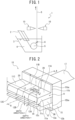
- FIG. 1 illustrates a schematic configuration of continuous hot-dip metal coating equipment provided with a gas wiping nozzle according to an embodiment of the present invention.
- the continuous hot-dip metal coating equipment 1 illustrated in FIG. 1 is equipment for continuously coating molten metal to the surface of a steel strip S as a metal strip by immersing the steel strip S in a molten metal bath 4 made of the molten metal, and then bringing the molten metal into a predetermined amount of coating.
- the continuous hot-dip metal coating equipment 1 includes a snout 2, a coating tank 3, a sink roll 5, and a support roll 6.
- the snout 2 is a member having a rectangular cross section perpendicular to the traveling direction of the steel strip S, which partitions a space through which the steel strip S passes.
- the upper end of the snout 2 is connected to, for example, the outlet side of a continuous annealing furnace, and the lower end is immersed in the molten metal bath 4 stored in the coating tank 3.
- the steel strip S annealed in the continuous annealing furnace in a reducing atmosphere passes through the snout 2 and is continuously introduced into the molten metal bath 4 in the coating tank 3. Thereafter, the steel strip S is pulled upward from the molten metal bath 4 via the sink roll 8 and the support roll 6 in the molten metal 4.
- Wiping gas is blown onto both surfaces of the steel strip S pulled upward from the molten metal bath 4 from a pair of gas wiping nozzles 10 (slits 14 described later) disposed on both surface sides of the steel strip S and the amount of molten metal coated to both surfaces of the steel strip S is adjusted. Thereafter, the steel strip S is cooled by cooling equipment (not illustrated) and guided to a subsequent step, and the hot-dip metal coated steel strip S is continuously manufactured.
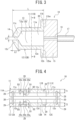
- each of the pair of gas wiping nozzles 10 disposed on both surface sides of the steel strip S includes a nozzle header 15 and a first nozzle member 11 disposed on the upper side and a second nozzle member 12 disposed on the lower side that are connected to the nozzle header 15, as illustrated in FIG. 2 .
- the first nozzle member 11 and the second nozzle member 12 are provided to face each other, and the slit 14 as a gas blowing port is formed so as to extend elongated in the length direction X between the end portions 11c and 12c, on the steel strip S side, of the first nozzle member 11 and the second nozzle member 12.
- Each gas wiping nozzle 10 is disposed on each surface side of the steel strip S so that the length direction X of the slit 14 is along the sheet width direction of the steel strip S, the width direction Z orthogonal to the length direction X of the slit 14 is along the sheet length direction of the steel strip S, and the depth direction Y of the slit 14 is along the sheet thickness direction of the steel strip S.
- the width direction Z of the slit is the same as the vertical direction of the gas wiping nozzle 10.
- the wiping gas is blown from the slit 14 toward one surface of the steel strip S from one of the gas wiping nozzles 10.
- the wiping gas is blown from the slit 14 toward the other surface of the steel strip S from the other gas wiping nozzle 10.
- each gas wiping nozzle 10 is configured to be longer than the sheet width of steel strip S so that the length of the slit 14 is longer than the sheet width of steel strip S, and extends outward from an end portion of the steel strip S in the width direction.
- the nozzle header 15 of each gas wiping nozzle 10 is formed in an approximately rectangular shape extending in the length direction X, the depth direction Y, and the width direction Y and is made from a metal such as chrome molybdenum steel.
- a gas supply pipe 17 is connected, and a gas supply path 16 communicating the gas supply pipe 27 with a hollow portion 13 described later is formed.
- the first nozzle member 11 placed at the upper side is divided, as illustrated in FIG. 2 , along the length direction X of the slit 14 on a plurality of divided faces 20 into a plurality of (three in the present embodiment) nozzle members 11A, 11B, 11C, as described in detail later.
- Each nozzle member 11A, 11B, 11C includes, as illustrated in FIG. 2 to FIG.
- a flat plate portion 11a extending in the length direction X and the depth direction (front-to-rear direction) Y and having a certain thickness T1
- a flange portion 11b protruding upward from the rear end of the flat plate portion 11a
- the above-described inclined end portion 11c extending obliquely downward from the front end of the flat plate portion 11a.
- a hollow portion-forming space 13a forming the hollow portion described later is formed below the flat plate portion 11a of each nozzle member 11A, 11B, 11C.
- the second nozzle member 12 placed at the lower side is also divided, as illustrated in FIG. 2 , along the length direction X of the slit 14 on a plurality of divided faces 20 into a plurality of (three in the present embodiment) nozzle members 12A, 12B, 12C.
- Each nozzle member 12A, 12B, 12C includes, as illustrated in FIG. 2 to FIG. 4 , a flat plate portion 12a extending in the length direction X and the depth direction (front-to-rear direction) Y and having a certain thickness T2, a flange portion 12b protruding upward from the rear end of the flat plate portion 12a, and the above-described inclined end portion 12c extending obliquely downward from the front end of the flat plate portion 12a.
- a hollow portion-forming space 13b forming the hollow portion described later is formed above the flat plate portion 12a of each nozzle member 12A, 12B, 12C.
- the first nozzle member 11 and the second nozzle member 12 are joined vertically and are fixed with the shim members 30 described later, and a rear end face 11ba of the flange portion 11b of the first nozzle member 11 and a rear end face 12ba of the flange portion 12b of the second nozzle member 12 are connected to a front face of the nozzle header 15.
- the hollow portion-forming space 13a formed by the first nozzle member 11 and the hollow portion-forming space 13b formed by the second nozzle member 12 accordingly form a hollow portion 13.
- the bottom face of the inclined end portion 11c at the steel strip S side of the first nozzle member 11 and the top face of the inclined end portion 12c at the steel strip S side of the second nozzle member 12 are flat faces facing together, and the above-described slit 14 as a gas blowing port is formed between the flat faces.
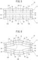
- the slit 14 is thin, extends in the length direction X as described above, and has a length L1 in the length direction X (see FIG. 2 ), a width or a gap L3 in the width direction Z orthogonal to the length direction X (see FIG. 3 ), and a depth L2 in the depth direction Y orthogonal to the length direction X (see FIG. 3 ) .
- the slit 14 may have any dimensions, but the length L1 of the slit 14 is set in consideration of a margin for the width of a steel strip S and may be set, for example, at about 1,500 to 2,500 mm.
- the gap L3 of the slit 14 may be set, for example, at about 0.5 to 3.0 mm.
- the depth L2 of the slit 14 may be set, for example, at about 5 to 30 mm.
- the slit 14 communicates with the hollow portion 13 in the depth direction Y.
- the hollow portion 13 functions as a pressure equalizing portion, and a wiping gas introduced from the gas supply pipe 17 through the gas supply path 16 into the hollow portion 13 is blown at a uniform pressure over the length direction X of the slit 14.
- Each gas wiping nozzle 10 includes, as illustrated in FIG. 2 to FIG. 4 , a pair of shim members 30 that adjust the gap L3 in the width direction Y orthogonal to the length direction X of the slit 14.
- each of the first nozzle member 11 and the second nozzle member 12 has a groove 28, 29 into which the shim member 30 is fitted as illustrated in FIG. 4 .
- the first nozzle member 11, the second nozzle member 12, and the shim members 30 are made from a ceramic material, a carbon material, a carbon fiber-reinforced carbon composite material, or a ceramic-based composite material, which has a low wettability to a molten metal such as molten zinc, is unlikely to undergo plastic deformation, and has a low linear expansion coefficient.
- the ceramic material include, but are not limited to, alumina, sialon, silicon nitride, zirconia, barium titanate, hydroxyapatite, silicon carbide (SiC), and fluorite
- examples of the carbon material include, but are not limited to, graphite. Graphite oxidizes and volatilizes in a highly oxidizing atmosphere, and thus the surface layer thereof is preferably coated with silica or the like.
- Invar and tungsten have a low linear expansion coefficient but undergo plastic deformation and thus are unsuitable as the materials of the first nozzle member 11, the second nozzle member 12, and the shim members 30, especially as the material of the shim members 30.
- the ceramic material, the carbon material, the carbon fiber-reinforced carbon composite material, or the ceramic-based composite material preferably has a flexural strength of 600 MPa and more preferably 800 MPa or more.
- the ceramic material is preferably zirconia, silicon nitride, sialon, or the like.
- the zinc adhesion amount partially increases on a part corresponding to the clogged part, and a linear defect is formed on a steel strip S in the same direction as the traveling direction of the steel strip S.
- the zinc adhering to the first nozzle member 11 and the second nozzle member 12 is thus removed by a special jig. In the removing, a nozzle surface having a low hardness may be cracked or chipped.
- the ceramic material, the carbon material, the carbon fiber-reinforced carbon composite material, or the ceramic-based composite material preferably has a Vickers hardness of 800 Hv or more and more preferably 1,000 Hv or more.
- the ceramic material, the carbon material, the carbon fiber-reinforced carbon composite material, or the ceramic-based composite material preferably has a fracture toughness of 5 MPa ⁇ m 1/2 or more and more preferably 5 MPa ⁇ m 1/2 or more.
- a nozzle material having a thermal shock resistance of not higher than the temperature of the high-temperature gas may cause cracking.
- the ceramic material, the carbon material, the carbon fiber-reinforced carbon composite material, or the ceramic-based composite material desirably has a thermal shock resistance of not less than the temperature of a used wiping gas, preferably has a thermal shock resistance of 430°C or more, and more preferably has a thermal shock resistance of 600°C or more.
- the first nozzle member 11 nozzle members 11A, 11B, 11C
- the second nozzle member 12 nozzle members 12A, 12B, 12C
- the linear expansion coefficient thereof is about 10 to 18 ⁇ 10 -6 /K.
- a monobloc product having a typical nozzle width of 1,500 mm or more is difficult to manufacture due to, for example, the restriction of the size of a furnace for sintering ceramics.
- the first nozzle member 11 is divided along the length direction X of the slit 14 on a plurality of divided faces 20 into a plurality of (three in the present embodiment) nozzle members 11A, 11B, 11C
- the second nozzle member 12 is divided along the length direction X of the slit 14 on a plurality of divided faces 20 into a plurality of (three in the present embodiment) nozzle members 12A, 12B, 12C.
- the dimension (D1 + D2 + D3) of the divided face 20 of the first nozzle member 11 is 1.5T1 or more where T1 is the thickness of the first nozzle member 11 in the width direction Z of the slit 14, and in a section of the second nozzle member 12 that is cut in the length direction X of the slit 14, at at least one point on the depth direction Y orthogonal to the length direction X of the slit 14, the dimension (D1 + D2 + D3) of the divided face 20 of the second nozzle member 12 is 1.5T2 or more where T2 is the thickness of the second nozzle member 12 in the width direction Z of the slit 14.
- T1 and T2 may be the same thickness or different thicknesses where T1 is the thickness of the first nozzle member 11 in the width direction Z of the slit 14, and T2 is the thickness of the second nozzle member 12 in the width direction Z of the slit 14.
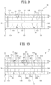
- the divided face 20 can have a linear shape parallel with the nozzle thickness direction (the width direction Z of the slit 14) and have a length equal to each thickness of the first nozzle member 11 and the second nozzle member 12 in the width direction Z of the slit 14, and an adhesive can be applied onto the divided faces 20 for assembly, as illustrated in FIG. 5 .
- the nozzle members 11B, 12B that are located at the center in the length direction X of the slit 14 and are not fixed vertically by a pair of shim members 30 are easily affected by a force in the width direction (Z direction in FIG. 1 ) orthogonal to the length direction of the slit 14, and heat deformation by an ejected high-temperature gas causes slippages 31 on the divided faces 20 in directions of expanding the gap of the slit 14 as illustrated in FIG. 6 .
- nozzle cleaning for removing zinc clogged in the slit 14 or the internal pressure of a gas may cause slippages 31 on the divided faces 20.
- the slippages 31 deform the hollow portion 13 as illustrated in FIG.
- the gap of the slit 14 deforms in the nozzle width direction.
- a gas is ejected in varies amounts in the length direction X of the slit 14 to vary the wiping performance in the length direction X of the slit 14.
- the coating amount on a steel strip S cannot be uniformized in the width direction of the steel strip S.
- FIG. 6 if a slit 14 has a larger gap, zinc splashed by a wiping gas is more likely to enter the slit 14. As a result, the slit 14 clogged with zinc is likely to cause uneven linear adhesion (linear marks).
- the nozzle members 11B, 12B located at the center in the length direction X of the slit 14 are required to be prevented from deforming in the width direction Z of the slit 14, or the fastening force between the nozzle members 11A, 11B, 11C, 12A, 12B, 12C is required to be increased.
- the fastening force between the nozzle members 11A, 11B, 11C, 12A, 12B, 12C is required to be increased.
- the dimension (D1 + D2 + D3) of each divided face 20 of the first nozzle member 11 is 1.5T1 or more where T1 is the thickness of the first nozzle member 11 (the thickness of the flat plate portion 11a) in the width direction Z of the slit 14, and in a section of the second nozzle member 12 that is cut in the length direction X of the slit 14, at at least one point on the depth direction Y, the dimension (D1 + D2 + D3) of each divided face 20 of the second nozzle member 12 is 1.5T2 or more where T2 is the thickness of the second nozzle member 12 (thickness of the flat plate portion 12a) in the width direction Z of the slit 14.
- each divided face 20 of the first nozzle member 11 and the second nozzle member 12 has a step 20b.
- each divided face 20 of the first nozzle member 11 includes a first linear portion 20a linearly extending downward from the top face of the first nozzle member 11 (flat plate portion 11a), a step 20b linearly extending outward from the lower end of the first linear portion 20a in the length direction X of the slit 14, and a second linear portion 20c linearly extending downward from an end of the step 20b to the bottom face of the first nozzle member 11 (flat plate portion 11a).
- Each divided face 20 of the second nozzle member 12 includes a first linear portion 20a linearly extending upward from the bottom face of the second nozzle member 12 (flat plate portion 12a), a step 20b linearly extending outward from the upper end of the first linear portion 20a in the length direction X of the slit 14, and a second linear portion 20c linearly extending upward from an end of the step 20b to the top face of the second nozzle member 12 (flat plate portion 12a).
- the total dimension (D1 + D2 + D3) of the dimension D1 of the first linear portion 20a, the dimension D2 of the step 20b, and the dimension D3 of the second linear portion 20c of each divided face 20 is 1.5T1 or more for the first nozzle member 11 and is 1.5T2 or more for the second nozzle member 12.
- each divided face 20 has a similar shape to that illustrated in FIG. 5 , and the nozzle members 11B, 12B located at the center in the length direction X of the slit 14 easily move in the width direction Z of the slit 14. The effect by the shape including the step 20b is thus unlikely to be exerted.
- each divided face 20 is more than 5T1 or 5T2
- the effect of improving the fastening force between the nozzle members 11A, 11B, 11C, 12A, 12B, 12C reaches the limit, and a divided face 20 having an excessively large dimension may crack.
- the upper limit of the dimension of the divided face 20 of the first nozzle member 11 is preferably 5T1
- the upper limit of the dimension of the divided face 20 of the second nozzle member 12 is preferably 5T2.
- each divided face 20 of the first nozzle member 11 and the second nozzle member 12 may have a taper shape that inclines with respect to the width direction Z of the slit 14 (vertical direction) as a gas wiping nozzle 10 pertaining to a first alternative embodiment and illustrated in FIG. 7 .
- each divided face 20 is inclined such that the dimension E1 of the divided face 20 is 1.5T1 or more for the first nozzle member 11 and is 1.5T2 or more for the second nozzle member 12.
- the upper limit of the dimension E1 of each divided face 20 is preferably 5T1 or 5T2.
- the gap of a slit 14 tends to expand due to the internal pressure of a gas or heat effect, and thus the nozzle division is designed under the concept of suppressing the gap expansion of the slit 14.
- a gap shrinkage of the slit 14 may become problematic.
- a divided face 20 having such a shape as illustrated in FIG. 8 or FIG. 9 suppresses the gap shrinkage of the slit 14.
- FIG. 8 illustrates a section of a gas wiping nozzle pertaining to a second alternative embodiment
- each divided face 20 of a first nozzle member 11 and a second nozzle member 12 has a symmetrical shape to the shape of each divided face 20 illustrated in FIG. 4 .
- each divided face 20 of the first nozzle member 11 includes a first linear portion 20a linearly extending downward from the top face of the first nozzle member 11 (flat plate portion 11a), a step 20b linearly extending inward from the lower end of the first linear portion 20a in the length direction X of the slit 14, and a second linear portion 20c linearly extending downward from an end of the step 20b to the bottom face of the first nozzle member 11 (flat plate portion 11a).
- Each divided face 20 of the second nozzle member 12 also includes a first linear portion 20a linearly extending upward from the bottom face of the second nozzle member 12 (flat plate portion 11a), a step 20b linearly extending inward from the upper end of the first linear portion 20a in the length direction X of the slit 14, and a second linear portion 20c linearly extending upward from an end of the step 20b to the top face of the second nozzle member 12 (flat plate portion 12a), where signs are not illustrated in FIG. 8 .
- the total dimension (D1 + D2 + D3) of the dimension D1 of the first linear portion 20a, the dimension D2 of the step 20b, and the dimension D3 of the second linear portion 20c of each divided face 20 is 1.5T1 or more for the first nozzle member 11 and is 1.5T2 or more for the second nozzle member 12.
- FIG. 9 illustrates a section of a gas wiping nozzle pertaining to a third alternative embodiment, and each divided face 20 of a first nozzle member 11 and a second nozzle member 12 has a symmetrical shape to the shape of each divided face 20 of the first nozzle member 11 and the second nozzle member 12 of the gas wiping nozzle 10 pertaining to the first alternative embodiment and illustrated in FIG. 7 .
- each member may be divided into four nozzle members 11A, 11B, 11C, 11D, 12A, 12B, 12C, 12D, as a gas wiping nozzle pertaining to a fourth alternative embodiment and illustrated in FIG. 10 .
- each divided face 20 of the first nozzle member 11 and the second nozzle member 12 may have such a fitting face shape that a concave face 20d and a convex face 20e of the adjacent divided nozzle members 11A and 11B, 11B and 11C, 11C and 11D, 12A and 12B, 12B and 12C, 12C and 12D fit together, as the gas wiping nozzle pertaining to the fourth alternative embodiment and illustrated in FIG. 10 .
- the adjacent divided nozzle members 11A and 11B will be described as an example.
- the divided face 20 has such a key shape that the concave face 20d formed on the nozzle member 11A fits the convex face 20e formed on the nozzle member 11B.
- the divided faces 20 have substantially the same dimension, and thus the dimension of the divided face 20 formed in the first nozzle member 11 will be described.
- the dimension of the divided face 20 is the sum of the dimension F1 of a first linear portion linearly extending downward from the top face of the first nozzle member 11 (flat plate portion 11a), the dimension F2 of a second linear portion linearly extending outward from the lower end of the first linear portion in the length direction X of the slit 14, the dimension F3 of a third linear portion linearly extending downward from an end of the second linear portion, the dimension F4 of a fourth linear portion linearly extending inward from the lower end of the third linear portion in the length direction X of the slit 14, and the dimension F5 of a fifth linear portion linearly extending downward from an end of the fourth linear portion to the bottom face of the first nozzle member 11 (flat plate portion 11a) .
- each divided face 20 of the first nozzle member 11 and the second nozzle member 12 have such a fitting face shape, the fastening force between the nozzle members 11A, 11B, 11C, 12A, 12B, 12C is increased, and even if an external force is applied to the divided faces 20 to expand or shrink the gap of the slit 14, the gap expansion or shrinkage is appropriately suppressed.
- the fitting face shape may be a dogleg shape.
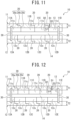
- each divided face 20 of the first nozzle member 11 and the second nozzle member 12 may have such a shape that the adjacent divided nozzle members 11A and 11B, 11B and 11C, 11C and 11D, 12A and 12B, 12B and 12C, 12C and 12D are engaged, as a gas wiping nozzle pertaining to a fifth alternative embodiment and illustrated in FIG. 11 .
- the dimension of each divided face 20 is the total dimension (D1 + D2 + D3) of the dimension D1 of a first linear portion 20a, the dimension D2 of a step 20b, and the dimension D3 of a second linear portion 20c as with the gas wiping nozzle 10 illustrated in FIG. 4 , is 1.5T1 or more for the first nozzle member 11, and is 1.5T2 or more for the second nozzle member 12.
- the gas wiping nozzle 10 pertaining to the second alternative embodiment and illustrated in FIG. 11 is an example in which a nozzle is divided into four members. For example, when divided into five members, the nozzle may have such a structure as a gas wiping nozzle 10 pertaining to a sixth alternative embodiment and illustrated in FIG. 12 .
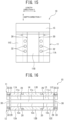
- pins 32 may be used to connect the divided nozzle members 11A and 11B, 11B and 11C of the first nozzle member 11 and the divided nozzle members 12A and 12B, 12B and 12C of the second nozzle member 12 as in a gas wiping nozzle pertaining to a seventh alternative embodiment and illustrated in FIG. 13 or in a gas wiping nozzle pertaining to an eighth alternative embodiment and illustrated in FIG. 14 .
- This increases the fastening force between the divided nozzle members 11A and 11B, 11B and 11C, 12A and 12B, 12B and 12C.
- the pin 32 may have a rectangular cross-sectional shape or a circular cross-sectional shape.
- the dimension of the pin 32 in the slit length direction X should be less than the dimension D2 of the step 20b.
- the dimension of the pin 32 in the slit length direction X should be less than the dimension between one end of the taper-shaped divided face 20 and the other end.
- any number of the pins 32 may be inserted in the slit length direction X and the slit depth direction Y at any positions.
- a method of fixing the first nozzle member 11 and the second nozzle member 12 will next be described with reference to FIG. 1 to FIG. 4 .
- the first nozzle member 11 and the second nozzle member 12 are first assembled. Before assembling the first nozzle member 11 and the second nozzle member 12, the nozzle member 11A and the nozzle member 11C of the first nozzle member 11 are grooved from the rear end face 11ba to form grooves 28, and the nozzle member 12A and the nozzle member 12C of the second nozzle member 12 are grooved from the rear end face 12ba to form grooves 29.
- the adjacent nozzle members 11A, 11B are fitted on the divided face 20, and an adhesive for ceramics is applied to fix the adjacent nozzle members 11A, 11B.
- the adjacent nozzle members 11B, 11C are fitted on the divided face 20, and an adhesive for ceramics is applied to fix the adjacent nozzle members 11B, 11C. Accordingly, the assembling the first nozzle member 11 is completed.
- the adjacent nozzle members 12A, 12B are fitted on the divided face 20, and an adhesive for ceramics is applied to fix the adjacent nozzle members 12A, 12B.
- the adjacent nozzle members 12B, 12C are fitted on the divided face 20, and an adhesive for ceramics is applied to fix the adjacent nozzle members 12B, 12C. Accordingly, the assembling the second nozzle member 12 is completed.
- the adhesive used to assemble the first nozzle member 11 and the second nozzle member 12 include, but are not limited to, an adhesive mainly containing zirconia and silica, an adhesive mainly containing alumina, and an adhesive mainly containing silica.
- the assembled first nozzle member 11 is placed at the upper side, and the assembled second nozzle member 12 is placed at the lower side.
- shim members 30 are fitted from the end faces 11ba, 12ba of the first nozzle member 11 and the second nozzle member 12 in a direction parallel with the extending direction of the grooves 28, 29.
- a similar adhesive to the above is applied to the grooves 28 of the first nozzle member 11 and the grooves 29 of the second nozzle member 12.
- the first nozzle member 11 and the second nozzle member 12 are fixed.
- the rear end face 11ba of the fixed first nozzle member 11 and the rear end face 12ba of the second nozzle member 12 may then be connected to the front-end face of the nozzle header 15 with fixing members such as screws (not illustrated).
- the dimension (D1 + D2 + D3) of each divided face 20 of the first nozzle member 11 is 1.5T1 or more where T1 is the thickness of the first nozzle member 11 (the thickness of the flat plate portion 11a) in the width direction Z of the slit 14, and in a section of the second nozzle member 12 that is cut in the length direction X of the slit 14, the dimension (D1 + D2 + D3) of each divided face 20 of the second nozzle member 12 is 1.5T2 or more where T2 is the thickness of the second nozzle member 12 (thickness of the flat plate portion 12a) in the width direction Z of the slit 14.
- the nozzle members 11B, 12B located at the center in the length direction X of the slit 14 are prevented from deforming in the width direction Z of the slit 14, or the fastening force between the nozzle members 11A, 11B, 11C, 12A, 12B, 12C is increased.
- the divided faces 20 do not slip in directions of expanding the gap L3 of the slit 14 due to heat deformation, and the gap L3 in the width direction Z orthogonal to the length direction X of the slit 14 is maintained to be constant over the length direction X of the slit 14.
- the gas ejection amount is constant in the length direction X of the slit 14, and the wiping performance does not fluctuate in the length direction X of the slit 14.
- the coating amount on a steel strip S is uniformized in the width direction of the steel strip S.
- the upper limit of the dimension (D1 + D2 + D3) of the divided face 20 of the first nozzle member 11 is 5T1
- the upper limit of the dimension (D1 + D2 + D3) of the divided face 20 of the second nozzle member 12 is 5T2. This prevents the nozzle members 11A, 11B, 11C, 12A, 12B, 12C included in the first nozzle member 11 and the second nozzle member 12 from cracking.
- the slit 14 maintains a constant gap. Under the condition, however, the first nozzle member 11 (the nozzle members 11A, 11B, 11C) and the second nozzle member 12 (the nozzle members 12A, 12B, 12C) may crack.
- the region in the depth direction Y where the dimension of each divided face 20 of the first nozzle member 11 and the second nozzle member 12 is 1.5T1 or more for the first nozzle member 11 and 1.5T2 or more for the second nozzle member 12 is preferably a region having a dimension of not less than 1/3 of the full dimension L (see FIG. 3 ) in the depth direction of each of the first nozzle member 11 and the second nozzle member 12 and is more preferably a region having the same dimension as the full dimension L.
- all the first nozzle member 11, the second nozzle member 12, and the shim members 30 are made from a ceramic material, a carbon material, a carbon fiber-reinforced carbon composite material, or a ceramic-based composite material, which has a small linear expansion coefficient, and the members have no difference in linear expansion coefficient. Accordingly, the gap L3 in the width direction orthogonal to the length direction X of the slit 14 as a gas blowing port is maintained to be constant over the length direction X of the slit even in a high temperature atmosphere.
- a nozzle header 15 also made from a ceramic material, a carbon material, a carbon fiber-reinforced carbon composite material, or a ceramic-based composite material is further effective in maintaining the gap L3 of the slit 14 to be constant, it is difficult to prepare a ceramic material, a carbon material, a carbon fiber-reinforced carbon composite material, or a ceramic-based composite material capable of withstanding a high-pressure wiping gas (capable of withstanding at least 60 kPa), and thus the nozzle header 15 is not made from a ceramic material, a carbon material, a carbon fiber-reinforced carbon composite material, or a ceramic-based composite material.
- a first lip part and a second lip part are fixed with a fixing member at the slit side in a nozzle chamber, and thus the slit gap can be prevented from varying after each assembly when some or all parts included in the gas wiping nozzle are exchanged.
- the fixing member to fix the upper and lower nozzle members, bolts used to fix the fixing members, and the like are made from a metal, and thus the fixing members, the bolts, and the like lengthen in a high temperature atmosphere. This changes the slit gap, and the slit gap cannot be maintained to be constant in the slit length direction.
- the first nozzle member 11 and the second nozzle member 12 are made from a ceramic material, a carbon material, a carbon fiber-reinforced carbon composite material, or a ceramic-based composite material
- the shim members 30 are made from a ceramic material, a carbon material, a carbon fiber-reinforced carbon composite material, or a ceramic-based composite material.
- the shim members 30 function to fix the first nozzle member 11 and the second nozzle member 12. This eliminates members that fix the first nozzle member 11 and the second nozzle member 12 but function to expand the gap L3 of the slit 14 in a high temperature atmosphere.
- the shim members 30 are made from a material unlikely to undergo plastic deformation and thus maintain the constant gap L3 of the slit 14 as a gas blowing port in the length direction X of the slit 14 even in a high temperature atmosphere.
- first nozzle member 11 and the second nozzle member 12 made from a ceramic material needs bolt holes, and metal bolts should be inserted into the bolt holes. In this case, torque during fastening the metal bolts or thermal expansion may damage the first nozzle member 11 and the second nozzle member 12 made from a ceramic material.
- the first nozzle member 11 and the second nozzle member 12 are made from a ceramic material, a carbon material, a carbon fiber-reinforced carbon composite material, or a ceramic-based composite material
- the shim members 30 are made from a ceramic material, a carbon material, a carbon fiber-reinforced carbon composite material, or a ceramic-based composite material.
- the shim members 30 function to fix the first nozzle member 11 and the second nozzle member 12. Hence, the first nozzle member 11 and the second nozzle member 12 are not damaged by torque during fastening metal bolts or thermal expansion.
- a gas wiping nozzle pertaining to a ninth alternative embodiment will next be described with reference to FIG. 16 and FIG. 17 .
- the gas wiping nozzle 10 illustrated in FIG. 16 and FIG. 17 has substantially the same basic configuration as the gas wiping nozzle 10 illustrated in FIG. 4 , but differs from the gas wiping nozzle 10 illustrated in FIG. 4 in that pins 33 are used to connect the grooves 28 of the first nozzle member 11 to the shim members 30, and pins 33 are used to connect the grooves 29 of the second nozzle member 12 to the shim members 30.
- Each section of the grooves 28 of the first nozzle member 11 and the grooves 29 of the second nozzle member 12 illustrated in FIG. 16 and FIG. 17 has a rectangular shape.
- the grooves 28 of the first nozzle member 11 extend forward from the rear end face 11ba (see FIG. 3 ).
- the grooves 29 of the second nozzle member 12 extend forward from the rear end face 12ba (see FIG. 3 ). Corners 28a in the grooves 28 and corners 29a in the grooves 29 may have a curved shape. This suppresses stress concentration to prevent breakage of the shim member 30.
- the shim member 30 has a rectangular parallelepiped shape and has a sectional shape allowing the shim member to be fitted into the groove 28 of the first nozzle member 11 or the groove 29 of the second nozzle member 12. As illustrated in FIG. 17 , the shim member 30 has a width C1 of about 5 to 20 mm corresponding to the width of the groove 28, 29, and the shim member 30 has a height C2 of about 5 to 40 mm.
- the shim members 30 are fitted into the grooves 28 of the first nozzle member 11 and the grooves 29 of the second nozzle member 12.
- a plurality of pins 33 are used to connect the grooves 28 of the first nozzle member 11 to the shim members 30 and to connect the grooves 29 of the second nozzle member 12 to the shim members 30.
- the shim members 70 can be fitted before the first nozzle member 11 and the second nozzle member 12 are combined, and this enables assembly without inserting shim members 70 from the rear end faces 11ba, 12ba of the first nozzle member 11 and the second nozzle member 12 into the grooves 28, 29.
- shim members 70 may be provided at a plurality of points in depth direction Y of the first nozzle member 11 and the second nozzle member 12, and this enables highly accurate holding of the gap L3 of the slit 14.
- pins 33 in the present embodiment, a total of four pins 33 are used: two pins are used to connect the grooves 28 of the first nozzle member 11 to the shim members 30; and two pins are used to connect the grooves 29 of the second nozzle member 12 to the shim members 30, as illustrated in FIG. 16 .
- the number of pins may be increased according to the number of shim members 30.
- the shim member 30 is fitted into the grooves 28, 29, and then a pin 33 is inserted from the side face of the first nozzle member 11 into the shim member 30 to a predetermined depth C3, as illustrated in FIG. 16 and FIG. 17 .
- the shim member 30 is fitted into the grooves 28, 29, and then a pin 33 is inserted from the side face of the second nozzle member 12 into the shim member 30 to a predetermined depth C3, as illustrated in FIG. 16 and FIG. 17 .
- each pin 33 is formed in a circular cylinder having a diameter C4 of about ⁇ 1 to 10 mm, and the insertion depth C3 of the pin 33 is about 1 to 15 mm, provided that the insertion depth C3 of the pin 33 ⁇ the width C1 of the shim member 30, and the diameter C4 of the pin 33 ⁇ the height C2 of the shim member 30.
- Each pin 33 is also preferably made from a ceramic material, a carbon material, a carbon fiber-reinforced carbon composite material, or a ceramic-based composite material.
- Each pin 33 preferably has a flexural strength of 600 MPa or more and more preferably 800 MPa or more.
- the ceramic material is preferably zirconia, silicon nitride, sialon, or the like.
- the gas wiping nozzle 10 illustrated in FIG. 16 and FIG. 17 When the gas wiping nozzle 10 illustrated in FIG. 16 and FIG. 17 is placed in a high temperature atmosphere, for example, when a wiping gas is heated, and accordingly the gas wiping nozzle 10 itself is heated, the nozzle header 15 made from a metal (see FIG. 1 and FIG. 2 ) would expand in the vertical direction or in the width direction Z of the slit 14 due to thermal expansion. Accordingly, the first nozzle member 11 and the second nozzle member 12 would move vertically apart due to the expansion. The first nozzle member 11 and the second nozzle member 12 are, however, connected to the shim members 30 with the pins 33, and the shim members 30 are unlikely to undergo plastic deformation. Hence, the first nozzle member 11 and the second nozzle member 12 do not move vertically apart.
- the first nozzle member 11 and the second nozzle member 12 do not move vertically apart, and thus the gap L3 of the slit 14 formed between the inclined end portions 11c, 12c at the steel strip S side of the first nozzle member 11 and the second nozzle member 12 is maintained.
- the temperature of the wiping gas it is preferable to control the temperature of the wiping gas so that the temperature T (°C) of the wiping gas immediately after being blown from the slit 14 of the gas wiping nozzle 10 satisfies T M - 150 ⁇ T ⁇ T M + 250 in relation to the melting point T M (°C) of the molten metal.
- T M melting point
- the temperature T (°C) of the wiping gas is less than T M - 150°C and is too low, the temperature T does not affect the fluidity of the molten metal and is not effective in suppressing the occurrence of hot metal wrinkles.
- the temperature T (°C) of the wiping gas is higher than T M +250°C, alloying is promoted and the appearance of the steel sheet is deteriorated.
- a method for raising the temperature of the wiping gas supplied to the gas wiping nozzle 10 is not particularly limited. Examples thereof include a method for heating with a heat exchanger and raising the temperature to supply, and a method for mixing the combustion exhaust gas of the annealing furnace with air.
- examples of the hot-dip metal coated metal strip manufactured by applying the gas wiping nozzle and the method for manufacturing the hot-dip metal coated metal strip according to the present embodiment include a hot-dip galvanized steel strip.
- the hot-dip galvanized steel strip includes both a coated steel sheet (GI) that is not subjected to an alloying treatment after the hot-dip galvanized treatment and a coated steel sheet (GA) that is subjected to the alloying treatment.
- the hot-dip metal coated metal strip manufactured by applying the gas wiping nozzle and the method for manufacturing the hot-dip metal coated metal strip according to the present embodiment is not limited thereto, and includes all hot-dip metal coated steel strips containing other molten metals such as aluminum and tin other than zinc.
- the number of divided members of each of the first nozzle member 11 and the second nozzle member 12 is three or four in the above description but may be two or five or more.
- each divided face 20 of the first nozzle member 11 is at least 1.5T1 or more where T1 is the thickness of the first nozzle member 11 in the width direction Z of the slit 14, and in a section of the second nozzle member 12 that is cut in the length direction X of the slit 14, the dimension of each divided face 20 of the second nozzle member 12 is at least 1.5T2 or more where T2 is the thickness of the second nozzle member 12 in the width direction Z of the slit 14.
- the shape of each divided face 20 is not limited to the shapes illustrated in FIG. 4 , FIG. 7 , FIG. 8 , FIG. 9 , FIG. 10 , FIG. 11, and FIG. 12 .
- the thickness of the flat plate portion 11a of the first nozzle member 11 and the thickness of the flat plate portion 12a of the second nozzle member 12 are set constant, but may be inconstant.
- the upper limit of the dimension of the divided face 20 of the first nozzle member 11 is 5T1
- the upper limit of the dimension of the divided face 20 of the second nozzle member 12 is 5T2
- the upper limits may be more than 5T1 and 5T2, respectively.
- All the first nozzle member 11, the second nozzle member 12, and the shim members 30 are made from a ceramic material, a carbon material, a carbon fiber-reinforced carbon composite material, or a ceramic-based composite material, but each of the first nozzle member 11, the second nozzle member 12, and the shim members 30 is not necessarily made from a ceramic material, a carbon material, a carbon fiber-reinforced carbon composite material, or a ceramic-based composite material.
- All the first nozzle member 11, the second nozzle member 12, and the shim members are made from a ceramic material, a carbon material, a carbon fiber-reinforced carbon composite material, or a ceramic-based composite material, but all the first nozzle member 11, the second nozzle member 12, and the shim members are not necessarily made from the same material. However, all the first nozzle member 11, the second nozzle member 12, and the shim members are preferably made from the same material. This can certainly eliminate a difference in linear expansion coefficient among the first nozzle member 11, the second nozzle member 12, and the shim members.
- Two independent shim members are not necessarily provided in the length direction X of the slit 14.
- the shim member may be an integral shim member having a connection part that connects portions fitted in the grooves of the nozzle members.
- the section of the groove 28, 29 is not limited to a rectangular shape but may be a dovetail groove shape, a T-groove shape, and other shapes.
- the sectional shape of the shim member 30 may be changed according to the sectional shape of the grooves 28, 29.
- the shape of the pin 33 is not necessarily a circular cylinder but may be a rectangular parallelepiped or other shapes.
- a continuous hot-dip metal coating equipment 1 having the basic configuration illustrated in FIG. 1 was used to manufacture a hot-dip galvanized steel strip by introducing a steel strip S having a sheet thickness of 1.0 mm and a sheet width of 1,200 mm into a molten zinc bath at a sheet speed of 2.0 m/s.
- a gas wiping nozzle 10 has a slit 14 having a length L1 of 1,800 mm, a depth L2 of 20 mm, and a width (gap) L3 of 1.2 mm.
- the quotient of the thickness of a divided face 20 of nozzle members 11A to 11C, 12A to 12C divided by the nozzle thickness T is as illustrated in Table 1 over the entire dimension in the depth direction Y.
- the molten zinc coating bath had a temperature of 460°C, and the gas temperature T was 500°C at the tip of the wiping nozzle.
- the wiping gas used was a mixed and adjusted gas of a flue gas from a combustor with air.
- the molten zinc coating bath had a melting point T M of 420°C.
- sialon had a flexural strength of 980 MPa, a Vickers hardness of 1,620 HV, a fracture toughness of 6 MPa ⁇ m 1/2 , a thermal shock resistance of 650°C, and a linear expansion coefficient of 3.2 ⁇ 10 -6 /K.
- Chrome molybdenum steel had a yield stress of 400 MPa, a Vickers hardness of 300 HV, a fracture toughness of 236 MPa ⁇ m 1/2 , and a linear expansion coefficient of 11.2 ⁇ 10 -6 /K.
- a first nozzle member 11, a second nozzle member 12, and shim members 30 made from sialon were used, and a nozzle header 15 made from chrome molybdenum steel was used.
- each of the first nozzle member 11 and the second nozzle member 12 was equally divided along the length direction X of the slit 14 into three nozzle members 11A, 11B, 11C, 12A, 12B, 12C (each nozzle member 11A, 11B, 11C, 12A, 12B, 12C had a length of 600 mm in the slit length direction X) .
- FIG. 1 a first nozzle member 11, a second nozzle member 12, and shim members 30 made from sialon were used, and a nozzle header 15 made from chrome molybdenum steel was used.
- each of the first nozzle member 11 and the second nozzle member 12 was equally divided along the length direction X of the slit 14 into three nozzle members 11A, 11B, 11C, 12A, 12B, 12C (each
- the divided face 20 had a shape including a step 20b, in which D1 was 10 mm, D2 was 12 mm, and D3 was 10 mm.
- the first nozzle member 11 had a thickness T1 of 20 mm
- the second nozzle member 12 had a thickness T2 of 20 mm.
- the first nozzle member 11 and the second nozzle member 12 were each assembled.
- the adjacent nozzle members 11A and 11B, 11B and 11C, 12A and 12B, 12B and 12C were fixed with an adhesive mainly containing zirconia and silica.
- the assembled first nozzle member 11 was placed at the upper side, and the assembled second nozzle member 12 was placed at the lower side.
- a first nozzle member 11, a second nozzle member 12, and shim members 30 made from sialon were used, and a nozzle header 15 made from chrome molybdenum steel was used.
- each of the first nozzle member 11 and the second nozzle member 12 was equally divided along the length direction X of the slit 14 into three nozzle members 11A, 11B, 11C, 12A, 12B, 12C (each nozzle member 11A, 11B, 11C, 12A, 12B, 12C had a length of 600 mm in the slit length direction X) .
- FIG. 1 a first nozzle member 11 and the second nozzle member 12 was equally divided along the length direction X of the slit 14 into three nozzle members 11A, 11B, 11C, 12A, 12B, 12C (each nozzle member 11A, 11B, 11C, 12A, 12B, 12C had a length of 600 mm in the slit length direction X) .
- the divided face 20 had a shape including a step 20b, in which D1 was 10 mm, D2 was 78 mm, and D3 was 10 mm.
- the first nozzle member 11 had a thickness T1 of 20 mm
- the second nozzle member 12 had a thickness T2 of 20 mm.
- the first nozzle member 11 and the second nozzle member 12 were each assembled, and the shim members 30 having a rectangular parallelepiped shape were fitted into grooves 28, 29 of the first nozzle member 11 and the second nozzle member 12 through an adhesive mainly containing alumina and silica.
- the nozzle header 15 was then fixed to the first nozzle member 11 and the second nozzle member 12.
- each of the first nozzle member 11 and the second nozzle member 12 was equally divided along the length direction X of the slit 14 into three nozzle members 11A, 11B, 11C, 12A, 12B, 12C (each nozzle member 11A, 11B, 11C, 12A, 12B, 12C had a length of 600 mm in the slit length direction X) .
- the divided face 20 had a taper shape, in which E1 was 32 mm.
- the first nozzle member 11 had a thickness T1 of 20 mm
- the second nozzle member 12 had a thickness T2 of 20 mm.
- the first nozzle member 11 and the second nozzle member 12 were each assembled, and the shim members 30 having a rectangular parallelepiped shape were fitted into grooves 28, 29 of the first nozzle member 11 and the second nozzle member 12 through an adhesive mainly containing alumina and silica.
- the nozzle header 15 was then fixed to the first nozzle member 11 and the second nozzle member 12.
- each of the first nozzle member 11 and the second nozzle member 12 was equally divided along the length direction X of the slit 14 into three nozzle members 11A, 11B, 11C, 12A, 12B, 12C (each nozzle member 11A, 11B, 11C, 12A, 12B, 12C had a length of 600 mm in the slit length direction X) .
- the divided face 20 had a taper shape, in which E1 was 98 mm.
- the first nozzle member 11 had a thickness T1 of 20 mm
- the second nozzle member 12 had a thickness T2 of 20 mm.
- the first nozzle member 11 and the second nozzle member 12 were each assembled, and the shim members 30 having a rectangular parallelepiped shape were fitted into grooves 28, 29 of the first nozzle member 11 and the second nozzle member 12 through an adhesive mainly containing alumina and silica.
- the nozzle header 15 was then fixed to the first nozzle member 11 and the second nozzle member 12.
- each of the first nozzle member 11 and the second nozzle member 12 was equally divided along the length direction X of the slit 14 into three nozzle members 11A, 11B, 11C, 12A, 12B, 12C (each nozzle member 11A, 11B, 11C, 12A, 12B, 12C had a length of 600 mm in the slit length direction X) .
- FIG. 13 each nozzle member 11A, 11B, 11C, 12A, 12B, 12C had a length of 600 mm in the slit length direction X
- the divided face 20 had a shape including a step 20b, in which D1 was 10 mm, D2 was 12 mm, and D3 was 10 mm.
- the first nozzle member 11 had a thickness T1 of 20 mm
- the second nozzle member 12 had a thickness T2 of 20 mm. Definitions of D1, D2, D3, and T are the same as in FIG. 4 .
- Each divided face 20 of the first nozzle member 11 and the second nozzle member 12 was subjected to drilling at two points in the nozzle depth direction Y with a tolerance of 8 ⁇ m + 10 ⁇ m.
- the adjacent nozzle members 11A and 11B, 11B and 11C, 12A and 12B, 12B and 12C were fixed on the divided faces 20 with an adhesive mainly containing zirconia and silica.
- an adhesive mainly containing zirconia and silica was applied to the drilled portions, and two pins 32 prepared to have a diameter of 8 mm with a tolerance of -10 ⁇ m were inserted into the drilled portions arranged in the slit depth direction Y as illustrated in FIG. 13 and FIG. 15 .
- the shim members 30 having a rectangular parallelepiped shape were fitted into grooves 28, 29 of the first nozzle member 11 and the second nozzle member 12 through an adhesive mainly containing alumina and silica, and the nozzle header 15 was finally fixed to the first nozzle member 11 and the second nozzle member 12.
- each of the first nozzle member 11 and the second nozzle member 12 was equally divided along the length direction X of the slit 14 into three nozzle members 11A, 11B, 11C, 12A, 12B, 12C (each nozzle member 11A, 11B, 11C, 12A, 12B, 12C had a length of 600 mm in the slit length direction X) .
- the divided face 20 had a taper shape, in which E1 was 32 mm.
- the first nozzle member 11 had a thickness T1 of 20 mm
- the second nozzle member 12 had a thickness T2 of 20 mm.
- Definitions of E1 and T are the same as in FIG. 7 .
- Each divided face 20 of the first nozzle member 11 and the second nozzle member 12 was subjected to drilling at two points in the nozzle depth direction Y with a tolerance of 8 ⁇ m + 10 ⁇ m.
- the adjacent nozzle members 11A and 11B, 11B and 11C, 12A and 12B, 12B and 12C were fixed on the divided faces 20 with an adhesive mainly containing zirconia and silica.
- a first nozzle member 11, a second nozzle member 12, and shim members 30 made from sialon were used, and a nozzle header 15 made from chrome molybdenum steel was used.
- each of the first nozzle member 11 and the second nozzle member 12 was equally divided along the length direction X of the slit 14 into three nozzle members 11A, 11B, 11C, 12A, 12B, 12C (each nozzle member 11A, 11B, 11C, 12A, 12B, 12C had a length of 600 mm in the slit length direction X) .
- FIG. 1 a first nozzle member 11 and the second nozzle member 12 was equally divided along the length direction X of the slit 14 into three nozzle members 11A, 11B, 11C, 12A, 12B, 12C (each nozzle member 11A, 11B, 11C, 12A, 12B, 12C had a length of 600 mm in the slit length direction X) .
- the divided face 20 had a shape including a step 20b, in which D1 was 10 mm, D2 was 82 mm, and D3 was 10 mm.
- the first nozzle member 11 had a thickness T1 of 20 mm
- the second nozzle member 12 had a thickness T2 of 20 mm.
- the first nozzle member 11 and the second nozzle member 12 were each assembled, and the shim members 30 having a rectangular parallelepiped shape were fitted into grooves 28, 29 of the first nozzle member 11 and the second nozzle member 12 through an adhesive mainly containing alumina and silica.
- the nozzle header 15 was then fixed to the first nozzle member 11 and the second nozzle member 12.
- a first nozzle member 11, a second nozzle member 12, and shim members 30 made from sialon were used, and a nozzle header 15 made from chrome molybdenum steel was used.
- each of the first nozzle member 11 and the second nozzle member 12 was equally divided along the length direction X of the slit 14 into three nozzle members 11A, 11B, 11C, 12A, 12B, 12C (each nozzle member 11A, 11B, 11C, 12A, 12B, 12C had a length of 600 mm in the slit length direction X) .
- the divided face 20 had a taper shape, in which E1 was 102 mm.
- the first nozzle member 11 had a thickness T1 of 20 mm
- the second nozzle member 12 had a thickness T2 of 20 mm.
- the first nozzle member 11 and the second nozzle member 12 were each assembled, and the shim members 30 having a rectangular parallelepiped shape were fitted into grooves 28, 29 of the first nozzle member 11 and the second nozzle member 12 through an adhesive mainly containing alumina and silica.
- the nozzle header 15 was then fixed to the first nozzle member 11 and the second nozzle member 12.
- a first nozzle member 11, a second nozzle member 12, and shim members 30 made from sialon were used, and a nozzle header 15 made from chrome molybdenum steel was used.
- each of the first nozzle member 11 and the second nozzle member 12 was equally divided along the length direction X of the slit 14 into four nozzle members 11A, 11B, 11C, 11D, 12A, 12B, 12C, 12D (each nozzle member 11A, 11B, 11C, 11D, 12A, 12B, 12C, 12D had a length of 450 mm in the slit length direction X).
- FIG. 11 each of the first nozzle member 11 and the second nozzle member 12 was equally divided along the length direction X of the slit 14 into four nozzle members 11A, 11B, 11C, 11D, 12A, 12B, 12C, 12D (each nozzle member 11A, 11B, 11C, 11D, 12A, 12B, 12C, 12D had a length of 450
- the divided face 20 had a shape including a step 20b, in which D1 was 10 mm, D2 was 12 mm, and D3 was 10 mm.
- the first nozzle member 11 had a thickness T1 of 20 mm
- the second nozzle member 12 had a thickness T2 of 20 mm.
- the first nozzle member 11 and the second nozzle member 12 were each assembled, and the shim members 30 having a rectangular parallelepiped shape were fitted into grooves 28, 29 of the first nozzle member 11 and the second nozzle member 12 through an adhesive mainly containing alumina and silica.
- the nozzle header 15 was then fixed to the first nozzle member 11 and the second nozzle member 12.
- a first nozzle member 11, a second nozzle member 12, and shim members 30 made from sialon were used, and a nozzle header 15 made from chrome molybdenum steel was used.
- each of the first nozzle member 11 and the second nozzle member 12 was equally divided along the length direction X of the slit 14 into four nozzle members 11A, 11B, 11C, 11D, 12A, 12B, 12C, 12D (each nozzle member 11A, 11B, 11C, 11D, 12A, 12B, 12C, 12D had a length of 450 mm in the slit length direction X).
- FIG. 11 each of the first nozzle member 11 and the second nozzle member 12 was equally divided along the length direction X of the slit 14 into four nozzle members 11A, 11B, 11C, 11D, 12A, 12B, 12C, 12D (each nozzle member 11A, 11B, 11C, 11D, 12A, 12B, 12C, 12D had a length of 450
- the divided face 20 had a shape including a step 20b, in which D1 was 10 mm, D2 was 78 mm, and D3 was 10 mm.
- the first nozzle member 11 had a thickness T1 of 20 mm
- the second nozzle member 12 had a thickness T2 of 20 mm.
- the first nozzle member 11 and the second nozzle member 12 were each assembled, and the shim members 30 having a rectangular parallelepiped shape were fitted into grooves 28, 29 of the first nozzle member 11 and the second nozzle member 12 through an adhesive mainly containing alumina and silica.
- the nozzle header 15 was then fixed to the first nozzle member 11 and the second nozzle member 12.
- each of the first nozzle member 11 and the second nozzle member 12 was equally divided along the length direction X of the slit 14 into four nozzle members 11A, 11B, 11C, 11D, 12A, 12B, 12C, 12D (each nozzle member 11A, 11B, 11C, 11D, 12A, 12B, 12C, 12D had a length of 450 mm in the slit length direction X).
- FIG. 11 each of the first nozzle member 11 and the second nozzle member 12 was equally divided along the length direction X of the slit 14 into four nozzle members 11A, 11B, 11C, 11D, 12A, 12B, 12C, 12D (each nozzle member 11A, 11B, 11C, 11D, 12A, 12B, 12C, 12D had a length of 450 mm in the slit length direction X).
- the divided face 20 had a shape including a step 20b, in which D1 was 10 mm, D2 was 82 mm, and D3 was 10 mm.
- the first nozzle member 11 had a thickness T1 of 20 mm
- the second nozzle member 12 had a thickness T2 of 20 mm.
- the first nozzle member 11 and the second nozzle member 12 were each assembled, and the shim members 30 having a rectangular parallelepiped shape were fitted into grooves 28, 29 of the first nozzle member 11 and the second nozzle member 12 through an adhesive mainly containing alumina and silica.
- the nozzle header 15 was then fixed to the first nozzle member 11 and the second nozzle member 12.
- each of the first nozzle member 11 and the second nozzle member 12 was equally divided along the length direction X of the slit 14 into five nozzle members 11A, 11B, 11C, 11D, 11E, 12A, 12B, 12C, 12D, 12E (each nozzle member 11A, 11B, 11C, 11D, 11E, 12A, 12B, 12C, 12D, 12E had a length of 450 mm in the slit length direction X).
- FIG. 12 each nozzle member 11A, 11B, 11C, 11D, 11E, 12A, 12B, 12C, 12D, 12E had a length of 450 mm in the slit length direction X).
- the divided face 20 had a shape including a step 20b, in which D1 was 10 mm, D2 was 12 mm, and D3 was 10 mm.
- the first nozzle member 11 had a thickness T1 of 20 mm
- the second nozzle member 12 had a thickness T2 of 20 mm.
- the first nozzle member 11 and the second nozzle member 12 were each assembled, and the shim members 30 having a rectangular parallelepiped shape were fitted into grooves 28, 29 of the first nozzle member 11 and the second nozzle member 12 through an adhesive mainly containing alumina and silica.
- the nozzle header 15 was then fixed to the first nozzle member 11 and the second nozzle member 12.
- each of the first nozzle member 11 and the second nozzle member 12 was equally divided along the length direction X of the slit 14 into five nozzle members 11A, 11B, 11C, 11D, 11E, 12A, 12B, 12C, 12D, 12E (each nozzle member 11A, 11B, 11C, 11D, 11E, 12A, 12B, 12C, 12D, 12E had a length of 450 mm in the slit length direction X).
- FIG. 12 each nozzle member 11A, 11B, 11C, 11D, 11E, 12A, 12B, 12C, 12D, 12E had a length of 450 mm in the slit length direction X).
- the divided face 20 had a shape including a step 20b, in which D1 was 10 mm, D2 was 78 mm, and D3 was 10 mm.
- the first nozzle member 11 had a thickness T1 of 20 mm
- the second nozzle member 12 had a thickness T2 of 20 mm.
- the first nozzle member 11 and the second nozzle member 12 were each assembled, and the shim members 30 having a rectangular parallelepiped shape were fitted into grooves 28, 29 of the first nozzle member 11 and the second nozzle member 12 through an adhesive mainly containing alumina and silica.
- the nozzle header 15 was then fixed to the first nozzle member 11 and the second nozzle member 12.
- a first nozzle member 11, a second nozzle member 12, and shim members 30 made from sialon were used, and a nozzle header 15 made from chrome molybdenum steel was used.
- each of the first nozzle member 11 and the second nozzle member 12 was equally divided along the length direction X of the slit 14 into five nozzle members 11A, 11B, 11C, 11D, 11E, 12A, 12B, 12C, 12D, 12E (each nozzle member 11A, 11B, 11C, 11D, 11E, 12A, 12B, 12C, 12D, 12E had a length of 450 mm in the slit length direction X).
- FIG. 12 each of the first nozzle member 11 and the second nozzle member 12 was equally divided along the length direction X of the slit 14 into five nozzle members 11A, 11B, 11C, 11D, 11E, 12A, 12B, 12C, 12D, 12E (each nozzle member 11A, 11B, 11C, 11D,
- the divided face 20 had a shape including a step 20b, in which D1 was 10 mm, D2 was 82 mm, and D3 was 10 mm.
- the first nozzle member 11 had a thickness T1 of 20 mm
- the second nozzle member 12 had a thickness T2 of 20 mm.
- the first nozzle member 11 and the second nozzle member 12 were each assembled, and the shim members 30 having a rectangular parallelepiped shape were fitted into grooves 28, 29 of the first nozzle member 11 and the second nozzle member 12 through an adhesive mainly containing alumina and silica.
- the nozzle header 15 was then fixed to the first nozzle member 11 and the second nozzle member 12.
- Comparative Example 1 a first nozzle member 11, a second nozzle member 12, and shim members 30 made from sialon were used, and a nozzle header 15 made from chrome molybdenum steel was used.
- each of the first nozzle member 11 and the second nozzle member 12 was equally divided along the length direction X of the slit 14 into three nozzle members 11A, 11B, 11C, 12A, 12B, 12C (each nozzle member 11A, 11B, 11C, 12A, 12B, 12C had a length of 600 mm in the slit length direction X) .
- FIG. 1 a first nozzle member 11, a second nozzle member 12, and shim members 30 made from sialon were used, and a nozzle header 15 made from chrome molybdenum steel was used.
- each of the first nozzle member 11 and the second nozzle member 12 was equally divided along the length direction X of the slit 14 into three nozzle members 11A, 11B, 11C, 12A, 12B, 12C
- the divided face 20 had a linear shape parallel with the nozzle thickness direction, and each divided face 20 had a dimension of 20 mm, which was the same as the thickness T1 of the first nozzle member 11 and the thickness T2 of the second nozzle member 12.
- the first nozzle member 11 and the second nozzle member 12 were each assembled with an adhesive mainly containing alumina and silica, and the shim members 30 having a rectangular parallelepiped shape were fitted into grooves 28, 29 of the first nozzle member 11 and the second nozzle member 12 through an adhesive mainly containing alumina and silica.
- the nozzle header 15 was then fixed to the first nozzle member 11 and the second nozzle member 12.
- a first nozzle member 11, a second nozzle member 12, and shim members 30 made from sialon were used, and a nozzle header 15 made from chrome molybdenum steel was used.
- each of the first nozzle member 11 and the second nozzle member 12 was equally divided along the length direction X of the slit 14 into three nozzle members 11A, 11B, 11C, 12A, 12B, 12C (each nozzle member 11A, 11B, 11C, 12A, 12B, 12C had a length of 600 mm in the slit length direction X) .
- FIG. 1 a first nozzle member 11 and the second nozzle member 12 was equally divided along the length direction X of the slit 14 into three nozzle members 11A, 11B, 11C, 12A, 12B, 12C (each nozzle member 11A, 11B, 11C, 12A, 12B, 12C had a length of 600 mm in the slit length direction X) .
- the divided face 20 had a shape including a step 20b, in which D1 was 10 mm, D2 was 8 mm, and D3 was 10 mm.
- the first nozzle member 11 had a thickness T1 of 20 mm
- the second nozzle member 12 had a thickness T2 of 20 mm.
- the first nozzle member 11 and the second nozzle member 12 were each assembled, and the shim members 30 having a rectangular parallelepiped shape were fitted into grooves 28, 29 of the first nozzle member 11 and the second nozzle member 12 through an adhesive mainly containing alumina and silica.
- the nozzle header 15 was then fixed to the first nozzle member 11 and the second nozzle member 12.
- a first nozzle member 11, a second nozzle member 12, and shim members 30 made from sialon were used, and a nozzle header 15 made from chrome molybdenum steel was used.
- each of the first nozzle member 11 and the second nozzle member 12 was equally divided along the length direction X of the slit 14 into three nozzle members 11A, 11B, 11C, 12A, 12B, 12C (each nozzle member 11A, 11B, 11C, 12A, 12B, 12C had a length of 600 mm in the slit length direction X).
- the divided face 20 had a taper shape, in which E1 was 28 mm.
- the first nozzle member 11 had a thickness T1 of 20 mm
- the second nozzle member 12 had a thickness T2 of 20 mm.
- the first nozzle member 11 and the second nozzle member 12 were each assembled, and the shim members 30 having a rectangular parallelepiped shape were fitted into grooves 28, 29 of the first nozzle member 11 and the second nozzle member 12 through an adhesive mainly containing alumina and silica.
- the nozzle header 15 was then fixed to the first nozzle member 11 and the second nozzle member 12.
- a first nozzle member 11, a second nozzle member 12, and shim members 30 made from sialon were used, and a nozzle header 15 made from chrome molybdenum steel was used.
- each of the first nozzle member 11 and the second nozzle member 12 was equally divided along the length direction X of the slit 14 into four nozzle members 11A, 11B, 11C, 11D, 12A, 12B, 12C, 12D (each nozzle member 11A, 11B, 11C, 11D, 12A, 12B, 12C, 12D had a length of 450 mm in the slit length direction X).
- FIG. 11 each of the first nozzle member 11 and the second nozzle member 12 was equally divided along the length direction X of the slit 14 into four nozzle members 11A, 11B, 11C, 11D, 12A, 12B, 12C, 12D (each nozzle member 11A, 11B, 11C, 11D, 12A, 12B, 12C, 12D had a length of 450
- the divided face 20 had a shape including a step 20b, in which D1 was 10 mm, D2 was 8 mm, and D3 was 10 mm.
- the first nozzle member 11 had a thickness T1 of 20 mm
- the second nozzle member 12 had a thickness T2 of 20 mm.
- the first nozzle member 11 and the second nozzle member 12 were each assembled, and the shim members 30 having a rectangular parallelepiped shape were fitted into grooves 28, 29 of the first nozzle member 11 and the second nozzle member 12 through an adhesive mainly containing alumina and silica.
- the nozzle header 15 was then fixed to the first nozzle member 11 and the second nozzle member 12.
- a first nozzle member 11, a second nozzle member 12, and shim members 30 made from sialon were used, and a nozzle header 15 made from chrome molybdenum steel was used.
- each of the first nozzle member 11 and the second nozzle member 12 was equally divided along the length direction X of the slit 14 into five nozzle members 11A, 11B, 11C, 11D, 11E, 12A, 12B, 12C, 12D, 12E (each nozzle member 11A, 11B, 11C, 11D, 11E, 12A, 12B, 12C, 12D, 12E had a length of 450 mm in the slit length direction X).
- FIG. 12 each of the first nozzle member 11 and the second nozzle member 12 was equally divided along the length direction X of the slit 14 into five nozzle members 11A, 11B, 11C, 11D, 11E, 12A, 12B, 12C, 12D, 12E (each nozzle member 11A, 11B, 11C, 11D,
- the divided face 20 had a shape including a step 20b, in which D1 was 10 mm, D2 was 8 mm, and D3 was 10 mm.
- the first nozzle member 11 had a thickness T1 of 20 mm
- the second nozzle member 12 had a thickness T2 of 20 mm.
- the first nozzle member 11 and the second nozzle member 12 were each assembled, and the shim members 30 having a rectangular parallelepiped shape were fitted into grooves 28, 29 of the first nozzle member 11 and the second nozzle member 12 through an adhesive mainly containing alumina and silica.
- the nozzle header 15 was then fixed to the first nozzle member 11 and the second nozzle member 12.
- the rate of the gap change of the slit 14 was evaluated.
- the rate (%) of the gap change of the slit 14 is a value (%) expressed by the maximum gap in the length direction X of the slit 14/the minimum gap ⁇ 100, and a nozzle having a rate of less than 110 (%) is acceptance.
- the coating amount deviation (%) on a steel strip S in the width direction is a value (%) expressed by the maximum coating amount on a steel strip S in the width direction/the minimum coating amount ⁇ 100, and a nozzle giving a deviation of less than 120 (%) is acceptance.
- the occurrence rate (%) of linear marks is the rate of the length of a steel strip S in which a linear mark defect was visually identified in an inspection process to the length of a steel strip S manufactured in each condition, and a nozzle giving a rate of less than 0.4 (%) is acceptance.
- the divided face had a dimension of more than 5T, and cracks were observed on each of the first nozzle member 11 and the second nozzle member 12 in nozzle overhaul inspection after manufacture, but the rate of the gap change of the slit 14, the coating amount deviation on a steel strip S in the width direction, and the occurrence rate of linear marks satisfied the acceptance standards, and each nozzle was acceptance.
- the temperature of the wiping gas is controlled so that the temperature T (°C) of the wiping gas immediately after being blown from the slit 14 of the gas wiping nozzle 10 satisfies T M - 150 ⁇ T ⁇ T M + 250 in relation to the melting point T M (°C) of the molten metal. Hence, no hot metal wrinkle defect was observed in each of Invention Examples 1 to 14 and Comparative Examples 1 to 5.
- the above results reveal that, by using the gas wiping nozzle and the method for manufacturing the hot-dip metal coated metal strip pertaining to the present invention, in which the gas wiping nozzle is manufactured from members divided along the length direction X of the slit 14 as a gas blowing port, the gap L3 in the width direction Z orthogonal to the length direction X of the slit 14 can be maintained to be constant over the length direction X of the slit 14 even in a high temperature atmosphere, and the coating amount on a steel strip S can be uniformized in the width direction of the steel strip S.
Landscapes
- Chemical & Material Sciences (AREA)
- Chemical Kinetics & Catalysis (AREA)
- Engineering & Computer Science (AREA)
- Materials Engineering (AREA)
- Mechanical Engineering (AREA)
- Metallurgy (AREA)
- Organic Chemistry (AREA)
- Coating With Molten Metal (AREA)
Abstract
Description
- The present invention relates to a gas wiping nozzle that blows gas onto a metal strip pulled up from a molten metal bath and adjusts the amount of a molten metal coated to a surface of the metal strip and a method for manufacturing a hot-dip metal coated metal strip using the gas wiping nozzle.
- A hot-dip galvanized steel sheet, which is a type of hot-dip metal coated steel sheets, is widely used in fields such as building materials, automobiles, and home appliances. In these applications, an excellent appearance is required for the hot-dip galvanized steel sheet. Here, since the appearance after painting is strongly affected by surface defects such as uneven coating thickness, flaws, and adhesion of foreign matter, it is important that the hot-dip galvanized steel sheet has no surface defects.
- In a continuous hot-dip metal coating line, normally, a steel strip as a metal strip annealed in a continuous annealing furnace in a reducing atmosphere passes through a snout and is introduced into a molten metal bath in a coating tank. The steel strip is pulled up above the molten metal bath via a sink roll and a support roll in the molten metal bath. Thereafter, the amount (hereinafter, also referred to as a basic weight amount) of molten metal coated is adjusted by blowing wiping gas from gas wiping nozzles located on both sides of the steel strip onto the surface of the steel strip and scraping off the excess molten metal coated to the surface of the steel strip and pulled up. Here, in order to correspond to various steel strip widths and also to cope with displacement in the width direction when the steel strip is pulled up, the gas wiping nozzle is normally configured to be wider than the width of the steel strip and extends outward from an end portion in the width direction of the steel strip.
- In such a gas wiping method, hot metal wrinkles (also referred to as hot metal sagging) with corrugated flow pattern are often generated on the coated surface due to minute vibration of the steel strip or irregular hot metal flow on the coating layer due to the blowing of wiping gas. In a case where the coated surface of a coated steel sheet with such hot metal wrinkles is used as a coating base surface in an outer coating application, a surface texture of a coating film, particularly smoothness, is impaired, and thus the coated steel sheet cannot be used for an exterior sheet to be suitable for a coating treatment having an excellent appearance, which significantly affects the yield of the coated steel sheet.
- In order to solve this problem, in the related art, for example, those described in PTL 1 are known.
- A continuous hot-dip metal coating method described in PTL 1 is a method in which a steel strip is continuously immersed in a molten metal coating bath, and gas is blown from a gas wiping nozzle onto the steel strip immediately after being drawn out from the molten metal coating bath to control the amount of coating. The temperature T of the wiping gas blown from the gas wiping nozzle is controlled according to a D/B value represented by a ratio of the distance D between a tip end of the gas wiping nozzle and the steel strip, and a gas wiping nozzle gap B.
- In addition, in the gas wiping method in the related art, a phenomenon that the edge portion of the steel strip may be supercooled from a central portion occurs during wiping, the steel strip may be warped, the amount of coating in the width direction may be uneven, and there may also be a problem of wasting a large amount of zinc in vain to guarantee the lower limit of the amount of zinc coated.
- In order to solve this problem, for example, a method described in
PTL 2 is known in the related art. - A wiping method in continuous hot-dip galvanizing described in
PTL 2 is a method of heating wiping gas such that the temperature TG (°C) of the wiping gas and the sheet thickness D (mm) of a steel strip to be coated satisfy the following equation (1), in the continuous hot-dip galvanizing, when the wiping gas is blown from a gas wiping nozzle to wipe the hot-dip zinc coating to the front and rear of the steel strip to be coated. - In addition, as the gas wiping nozzle in the related art, for example, a nozzle described in
PTL 3 is also known. - The gas wiping nozzle described in
PTL 3 is a nozzle that blows gas onto a steel strip pulled up above a molten metal coating bath and adjusts a film thickness of a molten metal film coated to the surface of the steel strip. The gas wiping nozzle includes a first lip portion and a second lip portion that are provided so as to face each other and form a nozzle chamber into which gas is introduced, a slit formed between the end portions of the first lip portion and the second lip portion on the steel strip side, as a blowing port for gas blown from the nozzle chamber, and a fixing member provided on the slit side in the nozzle chamber and fixing the first lip portion and the second lip portion. In the fixing member, a plurality of first communication holes that communicate the slit side and the opposite side of the slit with respect to the fixing member is disposed side by side along the width direction of the steel strip. - According to the gas wiping nozzle described in
PTL 3, even in a case where each part is reassembled in order to replace a part or all of the parts constituting the gas wiping nozzle, it is possible to suppress variations in a gap of the slit (hereinafter, also referred to as a slit gap) after assembly for each assembly. -
- PTL 1:
Japanese Patent No. 6011740 - PTL 2:
JP H8-176776 A - PTL 3:
JP 2018-178159 A - However, the continuous hot-dip metal coating method described in PTL 1, the wiping method in the continuous hot-dip galvanizing described in
PTL 2, and the gas wiping nozzle described inPTL 3 in the related art have the following problems. - In other words, in the continuous hot-dip metal coating method described in PTL 1 and the wiping method in the continuous hot-dip galvanizing described in
PTL 2, a wiping gas is heated, and accordingly the periphery of the gas wiping nozzle becomes a high temperature atmosphere. The gas wiping nozzle itself is also heated as the wiping gas is heated. PTL 1 andPTL 2 do not describe whether the gas wiping nozzle is manufactured as a monobloc product in the length direction of the slit as a gas blowing port that is provided at the steel strip-side end of the gas wiping nozzle or is manufactured from divided parts. A gas wiping nozzle may be difficult to manufacture as a monobloc product depending on the material of the gas wiping nozzle, and may be manufactured from parts divided along the slit length direction. When a gas wiping nozzle is manufactured from parts divided along the slit length direction, and the periphery of the gas wiping nozzle becomes a high temperature atmosphere, the slit as the gas blowing port may have uneven gaps in the width direction orthogonal to the length direction depending on the assembling manner of the gas wiping nozzle, and a steel strip may have uneven coating amounts in the width direction of the steel strip, unfortunately. - In the gas wiping nozzle disclosed in
PTL 3, a first lip portion and a second lip portion are fixed with a fixing member at the slit side in a nozzle chamber, and thus the slit gap can be prevented from varying after each assembly when some or all parts included in the gas wiping nozzle are exchanged. - In the gas wiping nozzle disclosed in
PTL 3, however, each of the upper first lip portion and the second lip portion is manufactured as a monobloc product in the length direction of the slit as the gas blowing port, and each of the first lip portion and the second lip portion is not manufactured from parts divided along the slit length direction. Manufacturing each of the first lip portion and the second lip portion from parts divided along the slit length direction should cause a similar problem to that when the above gas wiping nozzle is manufactured from parts divided along the slit length direction. - The present invention is therefore intended to solve the related art problems and to provide a gas wiping nozzle that is manufactured from parts divided along the length direction of a slit as a gas blowing port, maintains a gap to be constant in the width direction orthogonal to the length direction of the slit over the length direction of the slit even in a high temperature atmosphere, and makes the coating amount on a steel strip constant in the width direction of the steel strip and a method for manufacturing a hot-dip metal strip using the gas wiping nozzle.
- To solve the problems, a gas wiping nozzle pertaining to an aspect of the present invention is configured to blow a wiping gas onto a metal strip pulled up from a molten metal bath and adjust an amount of a molten metal coated to a surface of the metal strip. The gas wiping nozzle includes a first nozzle member and a second nozzle member, and has a slit as a gas blowing port between the first nozzle member and the second nozzle member, at a metal strip side end of the gas wiping nozzle. Each of the first nozzle member and the second nozzle member is divided along the length direction of the slit into a plurality of nozzle members, the dimension of a divided face of the first nozzle member is 1.5T1 or more in a section of the first nozzle member that is cut in the length direction of the slit, at at least one point on the depth direction orthogonal to the length direction of the slit where T1 is the thickness of the first nozzle member in the width direction of the slit, and the dimension of a divided face of the second nozzle member is 1.5T2 or more in a section of the second nozzle member that is cut in the length direction of the slit, at at least one point on the depth direction orthogonal to the length direction of the slit where T2 is the thickness of the second nozzle member in the width direction of the slit.
- A method for manufacturing a hot-dip metal coated metal strip pertaining to another aspect of the present invention includes disposing a pair of the gas wiping nozzles described above on both surface sides of a metal strip pulled up from a molten metal bath, and blowing wiping gas from each slit of the pair of gas wiping nozzles to each surface of the metal strip to adjust an amount of molten metal coated to both surfaces of the metal strip, continuously manufacturing a hot-dip metal coated metal strip.
- According to the gas wiping nozzle and the method for manufacturing a hot-dip metal coated metal strip pertaining to the present invention, a gas wiping nozzle that is manufactured from parts divided along the length direction of a slit as a gas blowing port, maintains a gap to be constant in the width direction orthogonal to the length direction of the slit over the length direction of the slit even in a high temperature atmosphere, and makes the coating amount on a steel strip constant in the width direction of the steel strip and a method for manufacturing a hot-dip metal strip using the gas wiping nozzle can be provided.
-
-
FIG. 1 is a schematic view illustrating a schematic configuration of continuous hot-dip metal coating equipment provided with a gas wiping nozzle according to an embodiment of the present invention; -
FIG. 2 is a perspective view illustrating a schematic configuration of the gas wiping nozzle used in the continuous hot-dip metal coating equipment illustrated inFIG. 1 ; -
FIG. 3 is a cross-sectional view taken along line A-A inFIG. 2 ; -
FIG. 4 is a cross-sectional view taken along line B-B inFIG. 3 ; -
FIG. 5 is a sectional view of a gas wiping nozzle pertaining to a reference example, similar toFIG. 4 ; -
FIG. 6 is a sectional view for describing how divided faces of a first nozzle member and a second nozzle member slip in the gas wiping nozzle pertaining to reference example illustrated inFIG. 5 ; -
FIG. 7 is a sectional view of a gas wiping nozzle pertaining to a first alternative embodiment, similar toFIG. 4 ; -
FIG. 8 is a sectional view of a gas wiping nozzle pertaining to a second alternative embodiment, similar toFIG. 4 ; -
FIG. 9 is a sectional view of a gas wiping nozzle pertaining to a third alternative embodiment, similar toFIG. 4 ; -
FIG. 10 is a sectional view of a gas wiping nozzle pertaining to a fourth alternative embodiment, similar toFIG. 4 ; -
FIG. 11 is a sectional view of a gas wiping nozzle pertaining to a fifth alternative embodiment, similar toFIG. 4 ; -
FIG. 12 is a sectional view of a gas wiping nozzle pertaining to a sixth alternative embodiment, similar toFIG. 4 ; -
FIG. 13 is a sectional view of a gas wiping nozzle pertaining to a seventh alternative embodiment, similar toFIG. 4 ; -
FIG. 14 is a sectional view of a gas wiping nozzle pertaining to an eighth alternative embodiment, similar toFIG. 4 ; -
FIG. 15 is a schematic plan view of the gas wiping nozzle pertaining to the seventh alternative embodiment illustrated inFIG. 13 . -
FIG. 16 is a sectional view of a gas wiping nozzle pertaining to a ninth alternative embodiment, similar toFIG. 4 ; and -
FIG. 17 is an enlarged view ofFIG. 16 including a groove of a first nozzle member, a groove of a second nozzle member, a shim member, and pins. - Hereinafter, embodiments of the present invention will be now described with reference to the drawings. The embodiments illustrated below exemplify devices and methods for embodying the technical idea of the present invention, and the technical idea of the present invention does not specify the material, shape, structure, arrangement, and the like of the component parts in the following embodiments.
- In addition, the drawings are schematic. Therefore, it should be noted that a relationship, ratio, and the like between a thickness and a plane dimension are different from the actual ones, and there are parts where the relationship and ratio of the dimensions are different between the drawings.
-
FIG. 1 illustrates a schematic configuration of continuous hot-dip metal coating equipment provided with a gas wiping nozzle according to an embodiment of the present invention. - The continuous hot-dip metal coating equipment 1 illustrated in
FIG. 1 is equipment for continuously coating molten metal to the surface of a steel strip S as a metal strip by immersing the steel strip S in amolten metal bath 4 made of the molten metal, and then bringing the molten metal into a predetermined amount of coating. - The continuous hot-dip metal coating equipment 1 includes a
snout 2, acoating tank 3, asink roll 5, and asupport roll 6. - The
snout 2 is a member having a rectangular cross section perpendicular to the traveling direction of the steel strip S, which partitions a space through which the steel strip S passes. The upper end of thesnout 2 is connected to, for example, the outlet side of a continuous annealing furnace, and the lower end is immersed in themolten metal bath 4 stored in thecoating tank 3. In the present embodiment, the steel strip S annealed in the continuous annealing furnace in a reducing atmosphere passes through thesnout 2 and is continuously introduced into themolten metal bath 4 in thecoating tank 3. Thereafter, the steel strip S is pulled upward from themolten metal bath 4 via the sink roll 8 and thesupport roll 6 in themolten metal 4. - Wiping gas is blown onto both surfaces of the steel strip S pulled upward from the
molten metal bath 4 from a pair of gas wiping nozzles 10 (slits 14 described later) disposed on both surface sides of the steel strip S and the amount of molten metal coated to both surfaces of the steel strip S is adjusted. Thereafter, the steel strip S is cooled by cooling equipment (not illustrated) and guided to a subsequent step, and the hot-dip metal coated steel strip S is continuously manufactured. - Here, each of the pair of
gas wiping nozzles 10 disposed on both surface sides of the steel strip S includes anozzle header 15 and afirst nozzle member 11 disposed on the upper side and asecond nozzle member 12 disposed on the lower side that are connected to thenozzle header 15, as illustrated inFIG. 2 . Thefirst nozzle member 11 and thesecond nozzle member 12 are provided to face each other, and theslit 14 as a gas blowing port is formed so as to extend elongated in the length direction X between theend portions first nozzle member 11 and thesecond nozzle member 12. Eachgas wiping nozzle 10 is disposed on each surface side of the steel strip S so that the length direction X of theslit 14 is along the sheet width direction of the steel strip S, the width direction Z orthogonal to the length direction X of theslit 14 is along the sheet length direction of the steel strip S, and the depth direction Y of theslit 14 is along the sheet thickness direction of the steel strip S. The width direction Z of the slit is the same as the vertical direction of thegas wiping nozzle 10. The wiping gas is blown from theslit 14 toward one surface of the steel strip S from one of thegas wiping nozzles 10. In addition, the wiping gas is blown from theslit 14 toward the other surface of the steel strip S from the othergas wiping nozzle 10. As a result, excess molten metal is scraped off on both surfaces of the steel strip S, the amount of coating (molten metal) is adjusted, and the amount of coating is made uniform in the sheet width direction and the sheet length direction of the steel strip S. In order to correspond to various sheet widths of steel strip S and to cope with displacement in the width direction when the steel strip S is pulled up, eachgas wiping nozzle 10 is configured to be longer than the sheet width of steel strip S so that the length of theslit 14 is longer than the sheet width of steel strip S, and extends outward from an end portion of the steel strip S in the width direction. - The
nozzle header 15 of eachgas wiping nozzle 10 is formed in an approximately rectangular shape extending in the length direction X, the depth direction Y, and the width direction Y and is made from a metal such as chrome molybdenum steel. To the base end (rear end) of thenozzle header 15, agas supply pipe 17 is connected, and agas supply path 16 communicating the gas supply pipe 27 with ahollow portion 13 described later is formed. - The
first nozzle member 11 placed at the upper side is divided, as illustrated inFIG. 2 , along the length direction X of theslit 14 on a plurality of divided faces 20 into a plurality of (three in the present embodiment)nozzle members nozzle member FIG. 2 to FIG. 4 , aflat plate portion 11a extending in the length direction X and the depth direction (front-to-rear direction) Y and having a certain thickness T1, aflange portion 11b protruding upward from the rear end of theflat plate portion 11a, and the above-describedinclined end portion 11c extending obliquely downward from the front end of theflat plate portion 11a. Below theflat plate portion 11a of eachnozzle member space 13a forming the hollow portion described later is formed. - The
second nozzle member 12 placed at the lower side is also divided, as illustrated inFIG. 2 , along the length direction X of theslit 14 on a plurality of divided faces 20 into a plurality of (three in the present embodiment)nozzle members nozzle member FIG. 2 to FIG. 4 , aflat plate portion 12a extending in the length direction X and the depth direction (front-to-rear direction) Y and having a certain thickness T2, aflange portion 12b protruding upward from the rear end of theflat plate portion 12a, and the above-describedinclined end portion 12c extending obliquely downward from the front end of theflat plate portion 12a. Above theflat plate portion 12a of eachnozzle member space 13b forming the hollow portion described later is formed. - The
first nozzle member 11 and thesecond nozzle member 12 are joined vertically and are fixed with theshim members 30 described later, and a rear end face 11ba of theflange portion 11b of thefirst nozzle member 11 and a rear end face 12ba of theflange portion 12b of thesecond nozzle member 12 are connected to a front face of thenozzle header 15. The hollow portion-formingspace 13a formed by thefirst nozzle member 11 and the hollow portion-formingspace 13b formed by thesecond nozzle member 12 accordingly form ahollow portion 13. - The bottom face of the
inclined end portion 11c at the steel strip S side of thefirst nozzle member 11 and the top face of theinclined end portion 12c at the steel strip S side of thesecond nozzle member 12 are flat faces facing together, and the above-describedslit 14 as a gas blowing port is formed between the flat faces. Theslit 14 is thin, extends in the length direction X as described above, and has a length L1 in the length direction X (seeFIG. 2 ), a width or a gap L3 in the width direction Z orthogonal to the length direction X (seeFIG. 3 ), and a depth L2 in the depth direction Y orthogonal to the length direction X (seeFIG. 3 ) . Theslit 14 may have any dimensions, but the length L1 of theslit 14 is set in consideration of a margin for the width of a steel strip S and may be set, for example, at about 1,500 to 2,500 mm. The gap L3 of theslit 14 may be set, for example, at about 0.5 to 3.0 mm. The depth L2 of theslit 14 may be set, for example, at about 5 to 30 mm. - The
slit 14 communicates with thehollow portion 13 in the depth direction Y. Thehollow portion 13 functions as a pressure equalizing portion, and a wiping gas introduced from thegas supply pipe 17 through thegas supply path 16 into thehollow portion 13 is blown at a uniform pressure over the length direction X of theslit 14. - Each
gas wiping nozzle 10 includes, as illustrated inFIG. 2 to FIG. 4 , a pair ofshim members 30 that adjust the gap L3 in the width direction Y orthogonal to the length direction X of theslit 14. - These
shim members 30 also function to fix thefirst nozzle member 11 and thesecond nozzle member 12. To fix thefirst nozzle member 11 and thesecond nozzle member 12 with theseshim members 30, each of thefirst nozzle member 11 and thesecond nozzle member 12, specifically, each of thenozzle members nozzle members groove shim member 30 is fitted as illustrated inFIG. 4 . - The
first nozzle member 11, thesecond nozzle member 12, and theshim members 30 are made from a ceramic material, a carbon material, a carbon fiber-reinforced carbon composite material, or a ceramic-based composite material, which has a low wettability to a molten metal such as molten zinc, is unlikely to undergo plastic deformation, and has a low linear expansion coefficient. Specifically, examples of the ceramic material include, but are not limited to, alumina, sialon, silicon nitride, zirconia, barium titanate, hydroxyapatite, silicon carbide (SiC), and fluorite, and examples of the carbon material include, but are not limited to, graphite. Graphite oxidizes and volatilizes in a highly oxidizing atmosphere, and thus the surface layer thereof is preferably coated with silica or the like. - Invar and tungsten have a low linear expansion coefficient but undergo plastic deformation and thus are unsuitable as the materials of the
first nozzle member 11, thesecond nozzle member 12, and theshim members 30, especially as the material of theshim members 30. - The ceramic material, the carbon material, the carbon fiber-reinforced carbon composite material, or the ceramic-based composite material preferably has a flexural strength of 600 MPa and more preferably 800 MPa or more. Hence, the ceramic material is preferably zirconia, silicon nitride, sialon, or the like. By using such a material, the members are unlikely to undergo plastic deformation, and deformation can be substantially suppressed at a disruptive strength or lower.
- If zinc adheres to the
first nozzle member 11 and thesecond nozzle member 12 to clog theslit 14 during operation of the apparatus, the zinc adhesion amount partially increases on a part corresponding to the clogged part, and a linear defect is formed on a steel strip S in the same direction as the traveling direction of the steel strip S. The zinc adhering to thefirst nozzle member 11 and thesecond nozzle member 12 is thus removed by a special jig. In the removing, a nozzle surface having a low hardness may be cracked or chipped. To prevent such cracking or chipping, the ceramic material, the carbon material, the carbon fiber-reinforced carbon composite material, or the ceramic-based composite material preferably has a Vickers hardness of 800 Hv or more and more preferably 1,000 Hv or more. For a similar reason, the ceramic material, the carbon material, the carbon fiber-reinforced carbon composite material, or the ceramic-based composite material preferably has a fracture toughness of 5 MPa·m1/2 or more and more preferably 5 MPa·m1/2 or more. - When a high-temperature gas is used as the wiping gas, a nozzle material having a thermal shock resistance of not higher than the temperature of the high-temperature gas may cause cracking. The ceramic material, the carbon material, the carbon fiber-reinforced carbon composite material, or the ceramic-based composite material desirably has a thermal shock resistance of not less than the temperature of a used wiping gas, preferably has a thermal shock resistance of 430°C or more, and more preferably has a thermal shock resistance of 600°C or more.
- From the viewpoint of suppressing nozzle deformation by heat, the first nozzle member 11 (
nozzle members nozzle members nozzle header 15 fixed to thefirst nozzle member 11 and thesecond nozzle member 12 and more preferably not more than 1/3 of that. As the material of thenozzle header 15, for example, stainless steel or the like is used, and the linear expansion coefficient thereof is about 10 to 18 × 10-6/K. - When a ceramic material is selected as the material unlikely to undergo plastic deformation, to manufacture the
first nozzle member 11 and thesecond nozzle member 12, a monobloc product having a typical nozzle width of 1,500 mm or more is difficult to manufacture due to, for example, the restriction of the size of a furnace for sintering ceramics. - When a carbon material is selected as the material unlikely to undergo plastic deformation, to manufacture the
first nozzle member 11 and thesecond nozzle member 12, similarly, a monobloc product having a typical nozzle width of 1,500 mm or more is difficult to manufacture due to, for example, the restriction of the size of a die used for forming. - When a carbon fiber-reinforced carbon composite material or a ceramic-based composite material is selected to manufacture the
first nozzle member 11 and thesecond nozzle member 12, similarly, a monobloc product having a typical nozzle width of 1,500 mm or more is difficult to manufacture due to the restriction of a furnace for forming. - Hence, when a ceramic material, a carbon material, a carbon fiber-reinforced carbon composite material, or a ceramic-based composite material is selected to manufacture the
first nozzle member 11 and thesecond nozzle member 12, as described above, thefirst nozzle member 11 is divided along the length direction X of theslit 14 on a plurality of divided faces 20 into a plurality of (three in the present embodiment)nozzle members second nozzle member 12 is divided along the length direction X of theslit 14 on a plurality of divided faces 20 into a plurality of (three in the present embodiment)nozzle members - In the present embodiment, as illustrated in
FIG. 4 , in a section of thefirst nozzle member 11 that is cut in the length direction X of theslit 14, at at least one point on the depth direction Y orthogonal to the length direction X of theslit 14, the dimension (D1 + D2 + D3) of the dividedface 20 of thefirst nozzle member 11 is 1.5T1 or more where T1 is the thickness of thefirst nozzle member 11 in the width direction Z of theslit 14, and in a section of thesecond nozzle member 12 that is cut in the length direction X of theslit 14, at at least one point on the depth direction Y orthogonal to the length direction X of theslit 14, the dimension (D1 + D2 + D3) of the dividedface 20 of thesecond nozzle member 12 is 1.5T2 or more where T2 is the thickness of thesecond nozzle member 12 in the width direction Z of theslit 14. - T1 and T2 may be the same thickness or different thicknesses where T1 is the thickness of the
first nozzle member 11 in the width direction Z of theslit 14, and T2 is the thickness of thesecond nozzle member 12 in the width direction Z of theslit 14. - The reason for the dimension of the divided
face 20 being 1.5T1 or 1.5T2 or more will next be described. - When each of the
first nozzle member 11 and thesecond nozzle member 12 is divided along the length direction X of theslit 14 on a plurality of divided faces 20 into a plurality ofnozzle members face 20 can have a linear shape parallel with the nozzle thickness direction (the width direction Z of the slit 14) and have a length equal to each thickness of thefirst nozzle member 11 and thesecond nozzle member 12 in the width direction Z of theslit 14, and an adhesive can be applied onto the divided faces 20 for assembly, as illustrated inFIG. 5 . - In the above method, however, the
nozzle members slit 14 and are not fixed vertically by a pair ofshim members 30 are easily affected by a force in the width direction (Z direction inFIG. 1 ) orthogonal to the length direction of theslit 14, and heat deformation by an ejected high-temperature gas causesslippages 31 on the divided faces 20 in directions of expanding the gap of theslit 14 as illustrated inFIG. 6 . In addition to this, nozzle cleaning for removing zinc clogged in theslit 14 or the internal pressure of a gas may causeslippages 31 on the divided faces 20. Theslippages 31 deform thehollow portion 13 as illustrated inFIG. 6 , and the gap of theslit 14 deforms in the nozzle width direction. From aslit 14 having a different gap shape, a gas is ejected in varies amounts in the length direction X of theslit 14 to vary the wiping performance in the length direction X of theslit 14. As a result, the coating amount on a steel strip S cannot be uniformized in the width direction of the steel strip S. As illustrated inFIG. 6 , if aslit 14 has a larger gap, zinc splashed by a wiping gas is more likely to enter theslit 14. As a result, theslit 14 clogged with zinc is likely to cause uneven linear adhesion (linear marks). - To solve the problems, the
nozzle members slit 14 are required to be prevented from deforming in the width direction Z of theslit 14, or the fastening force between thenozzle members FIG. 4 , in a section of thefirst nozzle member 11 that is cut in the length direction X of theslit 14, at at least one point on the depth direction Y, the dimension (D1 + D2 + D3) of each dividedface 20 of thefirst nozzle member 11 is 1.5T1 or more where T1 is the thickness of the first nozzle member 11 (the thickness of theflat plate portion 11a) in the width direction Z of theslit 14, and in a section of thesecond nozzle member 12 that is cut in the length direction X of theslit 14, at at least one point on the depth direction Y, the dimension (D1 + D2 + D3) of each dividedface 20 of thesecond nozzle member 12 is 1.5T2 or more where T2 is the thickness of the second nozzle member 12 (thickness of theflat plate portion 12a) in the width direction Z of theslit 14. - In
FIG. 4 , each dividedface 20 of thefirst nozzle member 11 and thesecond nozzle member 12 has astep 20b. In other words, each dividedface 20 of thefirst nozzle member 11 includes a firstlinear portion 20a linearly extending downward from the top face of the first nozzle member 11 (flat plate portion 11a), astep 20b linearly extending outward from the lower end of the firstlinear portion 20a in the length direction X of theslit 14, and a secondlinear portion 20c linearly extending downward from an end of thestep 20b to the bottom face of the first nozzle member 11 (flat plate portion 11a). Each dividedface 20 of thesecond nozzle member 12 includes a firstlinear portion 20a linearly extending upward from the bottom face of the second nozzle member 12 (flat plate portion 12a), astep 20b linearly extending outward from the upper end of the firstlinear portion 20a in the length direction X of theslit 14, and a secondlinear portion 20c linearly extending upward from an end of thestep 20b to the top face of the second nozzle member 12 (flat plate portion 12a). - The total dimension (D1 + D2 + D3) of the dimension D1 of the first
linear portion 20a, the dimension D2 of thestep 20b, and the dimension D3 of the secondlinear portion 20c of each dividedface 20 is 1.5T1 or more for thefirst nozzle member 11 and is 1.5T2 or more for thesecond nozzle member 12. - If the dimension (D1 + D2 + D3) of each divided
face 20 is less than 1.5T1 or 1.5T2, the dividedface 20 has a similar shape to that illustrated inFIG. 5 , and thenozzle members slit 14 easily move in the width direction Z of theslit 14. The effect by the shape including thestep 20b is thus unlikely to be exerted. - If the dimension (D1 + D2 + D3) of each divided
face 20 is more than 5T1 or 5T2, the effect of improving the fastening force between thenozzle members face 20 having an excessively large dimension may crack. Hence, the upper limit of the dimension of the dividedface 20 of thefirst nozzle member 11 is preferably 5T1, and the upper limit of the dimension of the dividedface 20 of thesecond nozzle member 12 is preferably 5T2. - To make each divided
face 20 have a dimension of 1.5T1 or more or 1.5T2 or more, each dividedface 20 of thefirst nozzle member 11 and thesecond nozzle member 12 may have a taper shape that inclines with respect to the width direction Z of the slit 14 (vertical direction) as agas wiping nozzle 10 pertaining to a first alternative embodiment and illustrated inFIG. 7 . In this case, each dividedface 20 is inclined such that the dimension E1 of the dividedface 20 is 1.5T1 or more for thefirst nozzle member 11 and is 1.5T2 or more for thesecond nozzle member 12. Even in this case, the upper limit of the dimension E1 of each dividedface 20 is preferably 5T1 or 5T2. - In the cases illustrated in
FIG. 4 andFIG. 7 , typically, the gap of aslit 14 tends to expand due to the internal pressure of a gas or heat effect, and thus the nozzle division is designed under the concept of suppressing the gap expansion of theslit 14. - In contrast, a gap shrinkage of the
slit 14 may become problematic. In such a case, a dividedface 20 having such a shape as illustrated inFIG. 8 orFIG. 9 suppresses the gap shrinkage of theslit 14. -
FIG. 8 illustrates a section of a gas wiping nozzle pertaining to a second alternative embodiment, and each dividedface 20 of afirst nozzle member 11 and asecond nozzle member 12 has a symmetrical shape to the shape of each dividedface 20 illustrated inFIG. 4 . In other words, each dividedface 20 of thefirst nozzle member 11 includes a firstlinear portion 20a linearly extending downward from the top face of the first nozzle member 11 (flat plate portion 11a), astep 20b linearly extending inward from the lower end of the firstlinear portion 20a in the length direction X of theslit 14, and a secondlinear portion 20c linearly extending downward from an end of thestep 20b to the bottom face of the first nozzle member 11 (flat plate portion 11a). Each dividedface 20 of thesecond nozzle member 12 also includes a firstlinear portion 20a linearly extending upward from the bottom face of the second nozzle member 12 (flat plate portion 11a), astep 20b linearly extending inward from the upper end of the firstlinear portion 20a in the length direction X of theslit 14, and a secondlinear portion 20c linearly extending upward from an end of thestep 20b to the top face of the second nozzle member 12 (flat plate portion 12a), where signs are not illustrated inFIG. 8 . - The total dimension (D1 + D2 + D3) of the dimension D1 of the first
linear portion 20a, the dimension D2 of thestep 20b, and the dimension D3 of the secondlinear portion 20c of each dividedface 20 is 1.5T1 or more for thefirst nozzle member 11 and is 1.5T2 or more for thesecond nozzle member 12. -
FIG. 9 illustrates a section of a gas wiping nozzle pertaining to a third alternative embodiment, and each dividedface 20 of afirst nozzle member 11 and asecond nozzle member 12 has a symmetrical shape to the shape of each dividedface 20 of thefirst nozzle member 11 and thesecond nozzle member 12 of thegas wiping nozzle 10 pertaining to the first alternative embodiment and illustrated inFIG. 7 . - When each of the
first nozzle member 11 and thesecond nozzle member 12 is divided along the length direction X of theslit 14 on a plurality of divided faces 20 into a plurality of nozzle members, unlike the case illustrated inFIG. 4 (each member is divided into three members), each member may be divided into fournozzle members FIG. 10 . - To make each divided
face 20 have a dimension of 1.5T1 or more or 1.5T2 or more, each dividedface 20 of thefirst nozzle member 11 and thesecond nozzle member 12 may have such a fitting face shape that aconcave face 20d and aconvex face 20e of the adjacent dividednozzle members FIG. 10 . The adjacent dividednozzle members face 20 has such a key shape that theconcave face 20d formed on thenozzle member 11A fits theconvex face 20e formed on thenozzle member 11B. - In the
gas wiping nozzle 10 pertaining to the fourth alternative embodiment and illustrated inFIG. 10 , the divided faces 20 have substantially the same dimension, and thus the dimension of the dividedface 20 formed in thefirst nozzle member 11 will be described. The dimension of the dividedface 20 is the sum of the dimension F1 of a first linear portion linearly extending downward from the top face of the first nozzle member 11 (flat plate portion 11a), the dimension F2 of a second linear portion linearly extending outward from the lower end of the first linear portion in the length direction X of theslit 14, the dimension F3 of a third linear portion linearly extending downward from an end of the second linear portion, the dimension F4 of a fourth linear portion linearly extending inward from the lower end of the third linear portion in the length direction X of theslit 14, and the dimension F5 of a fifth linear portion linearly extending downward from an end of the fourth linear portion to the bottom face of the first nozzle member 11 (flat plate portion 11a) . - By making each divided
face 20 of thefirst nozzle member 11 and thesecond nozzle member 12 have such a fitting face shape, the fastening force between thenozzle members slit 14, the gap expansion or shrinkage is appropriately suppressed. - To make each divided
face 20 have a fitting face shape, the fitting face shape may be a dogleg shape. - To make each divided
face 20 have a dimension of 1.5T1 or more or 1.5T2 or more, each dividedface 20 of thefirst nozzle member 11 and thesecond nozzle member 12 may have such a shape that the adjacent dividednozzle members FIG. 11 . - In the
gas wiping nozzle 10 pertaining to the fifth alternative embodiment and illustrated inFIG. 11 , the dimension of each dividedface 20 is the total dimension (D1 + D2 + D3) of the dimension D1 of a firstlinear portion 20a, the dimension D2 of astep 20b, and the dimension D3 of a secondlinear portion 20c as with thegas wiping nozzle 10 illustrated inFIG. 4 , is 1.5T1 or more for thefirst nozzle member 11, and is 1.5T2 or more for thesecond nozzle member 12. Thegas wiping nozzle 10 pertaining to the second alternative embodiment and illustrated inFIG. 11 is an example in which a nozzle is divided into four members. For example, when divided into five members, the nozzle may have such a structure as agas wiping nozzle 10 pertaining to a sixth alternative embodiment and illustrated inFIG. 12 . - To increase the fastening force between
nozzle members nozzle members first nozzle member 11 and the dividednozzle members second nozzle member 12 as in a gas wiping nozzle pertaining to a seventh alternative embodiment and illustrated inFIG. 13 or in a gas wiping nozzle pertaining to an eighth alternative embodiment and illustrated inFIG. 14 . This increases the fastening force between the dividednozzle members - The
pin 32 may have a rectangular cross-sectional shape or a circular cross-sectional shape. In the gas wiping nozzle pertaining to the seventh alternative embodiment and illustrated inFIG. 13 , when thepin 32 is inserted into thestep 20b of the dividedface 20 in the width direction Z of theslit 14, the dimension of thepin 32 in the slit length direction X should be less than the dimension D2 of thestep 20b. - In the gas wiping nozzle pertaining to the eighth alternative embodiment and illustrated in
FIG. 14 , when thepin 32 is inserted into the taper-shaped dividedface 20 in the width direction Z of theslit 14, the dimension of thepin 32 in the slit length direction X should be less than the dimension between one end of the taper-shaped dividedface 20 and the other end. - In the gas wiping nozzle pertaining to the seventh alternative embodiment and illustrated in
FIG. 13 and the gas wiping nozzle pertaining to the eighth alternative embodiment and illustrated inFIG. 14 , when pins 32 are inserted as illustrated inFIG. 15 , any number of thepins 32 may be inserted in the slit length direction X and the slit depth direction Y at any positions. - A method of fixing the
first nozzle member 11 and thesecond nozzle member 12 will next be described with reference toFIG. 1 to FIG. 4 . - The
first nozzle member 11 and thesecond nozzle member 12 are first assembled. Before assembling thefirst nozzle member 11 and thesecond nozzle member 12, thenozzle member 11A and thenozzle member 11C of thefirst nozzle member 11 are grooved from the rear end face 11ba to formgrooves 28, and thenozzle member 12A and thenozzle member 12C of thesecond nozzle member 12 are grooved from the rear end face 12ba to formgrooves 29. - To assemble the
first nozzle member 11, theadjacent nozzle members face 20, and an adhesive for ceramics is applied to fix theadjacent nozzle members adjacent nozzle members face 20, and an adhesive for ceramics is applied to fix theadjacent nozzle members first nozzle member 11 is completed. - To assemble the
second nozzle member 12, theadjacent nozzle members face 20, and an adhesive for ceramics is applied to fix theadjacent nozzle members adjacent nozzle members face 20, and an adhesive for ceramics is applied to fix theadjacent nozzle members second nozzle member 12 is completed. Examples of the adhesive used to assemble thefirst nozzle member 11 and thesecond nozzle member 12 include, but are not limited to, an adhesive mainly containing zirconia and silica, an adhesive mainly containing alumina, and an adhesive mainly containing silica. - The assembled
first nozzle member 11 is placed at the upper side, and the assembledsecond nozzle member 12 is placed at the lower side. To thegrooves 28 of thefirst nozzle member 11 and to thegrooves 29 of thesecond nozzle member 12,shim members 30 are fitted from the end faces 11ba, 12ba of thefirst nozzle member 11 and thesecond nozzle member 12 in a direction parallel with the extending direction of thegrooves grooves 28 of thefirst nozzle member 11 and thegrooves 29 of thesecond nozzle member 12. - Accordingly, the
first nozzle member 11 and thesecond nozzle member 12 are fixed. - The rear end face 11ba of the fixed
first nozzle member 11 and the rear end face 12ba of thesecond nozzle member 12 may then be connected to the front-end face of thenozzle header 15 with fixing members such as screws (not illustrated). - When the
gas wiping nozzle 10 pertaining to the present embodiment is placed in a high temperature atmosphere, and a high-temperature gas is ejected from theslit 14, heat deformation during the ejection would cause slippages on the divided faces 20 in directions of expanding the gap L3 of theslit 14. In the present embodiment, as illustrated inFIG. 4 , in a section of thefirst nozzle member 11 that is cut in the length direction X of theslit 14, the dimension (D1 + D2 + D3) of each dividedface 20 of thefirst nozzle member 11 is 1.5T1 or more where T1 is the thickness of the first nozzle member 11 (the thickness of theflat plate portion 11a) in the width direction Z of theslit 14, and in a section of thesecond nozzle member 12 that is cut in the length direction X of theslit 14, the dimension (D1 + D2 + D3) of each dividedface 20 of thesecond nozzle member 12 is 1.5T2 or more where T2 is the thickness of the second nozzle member 12 (thickness of theflat plate portion 12a) in the width direction Z of theslit 14. Hence, thenozzle members slit 14 are prevented from deforming in the width direction Z of theslit 14, or the fastening force between thenozzle members slit 14 due to heat deformation, and the gap L3 in the width direction Z orthogonal to the length direction X of theslit 14 is maintained to be constant over the length direction X of theslit 14. Accordingly, the gas ejection amount is constant in the length direction X of theslit 14, and the wiping performance does not fluctuate in the length direction X of theslit 14. As a result, the coating amount on a steel strip S is uniformized in the width direction of the steel strip S. - In the
gas wiping nozzle 10 pertaining to the present embodiment, the upper limit of the dimension (D1 + D2 + D3) of the dividedface 20 of thefirst nozzle member 11 is 5T1, and the upper limit of the dimension (D1 + D2 + D3) of the dividedface 20 of thesecond nozzle member 12 is 5T2. This prevents thenozzle members first nozzle member 11 and thesecond nozzle member 12 from cracking. - In
FIG. 2 , when each of thefirst nozzle member 11 and thesecond nozzle member 12 has a dividedface 20 having a dimension of 1.5T1 or more or 1.5T2 or more in a section of the members cut at at least one point in the depth direction Y, theslit 14 maintains a constant gap. Under the condition, however, the first nozzle member 11 (thenozzle members nozzle members face 20 of thefirst nozzle member 11 and thesecond nozzle member 12 is 1.5T1 or more for thefirst nozzle member 11 and 1.5T2 or more for thesecond nozzle member 12 is preferably a region having a dimension of not less than 1/3 of the full dimension L (seeFIG. 3 ) in the depth direction of each of thefirst nozzle member 11 and thesecond nozzle member 12 and is more preferably a region having the same dimension as the full dimension L. - In the
gas wiping nozzle 10 pertaining to the present embodiment, all thefirst nozzle member 11, thesecond nozzle member 12, and theshim members 30 are made from a ceramic material, a carbon material, a carbon fiber-reinforced carbon composite material, or a ceramic-based composite material, which has a small linear expansion coefficient, and the members have no difference in linear expansion coefficient. Accordingly, the gap L3 in the width direction orthogonal to the length direction X of theslit 14 as a gas blowing port is maintained to be constant over the length direction X of the slit even in a high temperature atmosphere. - Although using a
nozzle header 15 also made from a ceramic material, a carbon material, a carbon fiber-reinforced carbon composite material, or a ceramic-based composite material is further effective in maintaining the gap L3 of theslit 14 to be constant, it is difficult to prepare a ceramic material, a carbon material, a carbon fiber-reinforced carbon composite material, or a ceramic-based composite material capable of withstanding a high-pressure wiping gas (capable of withstanding at least 60 kPa), and thus thenozzle header 15 is not made from a ceramic material, a carbon material, a carbon fiber-reinforced carbon composite material, or a ceramic-based composite material. - In the gas wiping nozzle disclosed in
PTL 3, a first lip part and a second lip part are fixed with a fixing member at the slit side in a nozzle chamber, and thus the slit gap can be prevented from varying after each assembly when some or all parts included in the gas wiping nozzle are exchanged. - In the gas wiping nozzle disclosed in
PTL 3, however, the fixing member to fix the upper and lower nozzle members, bolts used to fix the fixing members, and the like are made from a metal, and thus the fixing members, the bolts, and the like lengthen in a high temperature atmosphere. This changes the slit gap, and the slit gap cannot be maintained to be constant in the slit length direction. - In contrast, in the
gas wiping nozzle 10 pertaining to the present embodiment, not only thefirst nozzle member 11 and thesecond nozzle member 12 are made from a ceramic material, a carbon material, a carbon fiber-reinforced carbon composite material, or a ceramic-based composite material, but also theshim members 30 are made from a ceramic material, a carbon material, a carbon fiber-reinforced carbon composite material, or a ceramic-based composite material. In addition, theshim members 30 function to fix thefirst nozzle member 11 and thesecond nozzle member 12. This eliminates members that fix thefirst nozzle member 11 and thesecond nozzle member 12 but function to expand the gap L3 of theslit 14 in a high temperature atmosphere. Theshim members 30 are made from a material unlikely to undergo plastic deformation and thus maintain the constant gap L3 of theslit 14 as a gas blowing port in the length direction X of theslit 14 even in a high temperature atmosphere. - If
shim members 30 have no function to fix thefirst nozzle member 11 and thesecond nozzle member 12, and thefirst nozzle member 11 and thesecond nozzle member 12 made from a ceramic material are fixed with metal bolts, thefirst nozzle member 11 and thesecond nozzle member 12 made from a ceramic material needs bolt holes, and metal bolts should be inserted into the bolt holes. In this case, torque during fastening the metal bolts or thermal expansion may damage thefirst nozzle member 11 and thesecond nozzle member 12 made from a ceramic material. - In contrast, in the
gas wiping nozzle 10 pertaining to the present embodiment, not only thefirst nozzle member 11 and thesecond nozzle member 12 are made from a ceramic material, a carbon material, a carbon fiber-reinforced carbon composite material, or a ceramic-based composite material, but also theshim members 30 are made from a ceramic material, a carbon material, a carbon fiber-reinforced carbon composite material, or a ceramic-based composite material. In addition, theshim members 30 function to fix thefirst nozzle member 11 and thesecond nozzle member 12. Hence, thefirst nozzle member 11 and thesecond nozzle member 12 are not damaged by torque during fastening metal bolts or thermal expansion. - A gas wiping nozzle pertaining to a ninth alternative embodiment will next be described with reference to
FIG. 16 andFIG. 17 . - The
gas wiping nozzle 10 illustrated inFIG. 16 andFIG. 17 has substantially the same basic configuration as thegas wiping nozzle 10 illustrated inFIG. 4 , but differs from thegas wiping nozzle 10 illustrated inFIG. 4 in that pins 33 are used to connect thegrooves 28 of thefirst nozzle member 11 to theshim members 30, and pins 33 are used to connect thegrooves 29 of thesecond nozzle member 12 to theshim members 30. - Each section of the
grooves 28 of thefirst nozzle member 11 and thegrooves 29 of thesecond nozzle member 12 illustrated inFIG. 16 andFIG. 17 has a rectangular shape. Thegrooves 28 of thefirst nozzle member 11 extend forward from the rear end face 11ba (seeFIG. 3 ). Thegrooves 29 of thesecond nozzle member 12 extend forward from the rear end face 12ba (seeFIG. 3 ).Corners 28a in thegrooves 28 andcorners 29a in thegrooves 29 may have a curved shape. This suppresses stress concentration to prevent breakage of theshim member 30. - The
shim member 30 has a rectangular parallelepiped shape and has a sectional shape allowing the shim member to be fitted into thegroove 28 of thefirst nozzle member 11 or thegroove 29 of thesecond nozzle member 12. As illustrated inFIG. 17 , theshim member 30 has a width C1 of about 5 to 20 mm corresponding to the width of thegroove shim member 30 has a height C2 of about 5 to 40 mm. - To fix the
first nozzle member 11 and thesecond nozzle member 12, theshim members 30 are fitted into thegrooves 28 of thefirst nozzle member 11 and thegrooves 29 of thesecond nozzle member 12. A plurality ofpins 33 are used to connect thegrooves 28 of thefirst nozzle member 11 to theshim members 30 and to connect thegrooves 29 of thesecond nozzle member 12 to theshim members 30. As described above, in the seventh alternative embodiment, the shim members 70 can be fitted before thefirst nozzle member 11 and thesecond nozzle member 12 are combined, and this enables assembly without inserting shim members 70 from the rear end faces 11ba, 12ba of thefirst nozzle member 11 and thesecond nozzle member 12 into thegrooves first nozzle member 11 and thesecond nozzle member 12, and this enables highly accurate holding of the gap L3 of theslit 14. - As for
pins 33, in the present embodiment, a total of fourpins 33 are used: two pins are used to connect thegrooves 28 of thefirst nozzle member 11 to theshim members 30; and two pins are used to connect thegrooves 29 of thesecond nozzle member 12 to theshim members 30, as illustrated inFIG. 16 . To provideshim members 30 at a plurality of points in the depth direction Y of thefirst nozzle member 11 and thesecond nozzle member 12, the number of pins may be increased according to the number ofshim members 30. - To connect the
groove 28 of thefirst nozzle member 11 to theshim member 30, theshim member 30 is fitted into thegrooves pin 33 is inserted from the side face of thefirst nozzle member 11 into theshim member 30 to a predetermined depth C3, as illustrated inFIG. 16 andFIG. 17 . Similarly, to connect thegroove 29 of thesecond nozzle member 12 to theshim member 30, theshim member 30 is fitted into thegrooves pin 33 is inserted from the side face of thesecond nozzle member 12 into theshim member 30 to a predetermined depth C3, as illustrated inFIG. 16 andFIG. 17 . - In the present embodiment, each
pin 33 is formed in a circular cylinder having a diameter C4 of about Φ 1 to 10 mm, and the insertion depth C3 of thepin 33 is about 1 to 15 mm, provided that the insertion depth C3 of thepin 33 < the width C1 of theshim member 30, and the diameter C4 of thepin 33 < the height C2 of theshim member 30. Eachpin 33 is also preferably made from a ceramic material, a carbon material, a carbon fiber-reinforced carbon composite material, or a ceramic-based composite material. Eachpin 33 preferably has a flexural strength of 600 MPa or more and more preferably 800 MPa or more. Hence, the ceramic material is preferably zirconia, silicon nitride, sialon, or the like. - When the
gas wiping nozzle 10 illustrated inFIG. 16 andFIG. 17 is placed in a high temperature atmosphere, for example, when a wiping gas is heated, and accordingly thegas wiping nozzle 10 itself is heated, thenozzle header 15 made from a metal (seeFIG. 1 and FIG. 2 ) would expand in the vertical direction or in the width direction Z of theslit 14 due to thermal expansion. Accordingly, thefirst nozzle member 11 and thesecond nozzle member 12 would move vertically apart due to the expansion. Thefirst nozzle member 11 and thesecond nozzle member 12 are, however, connected to theshim members 30 with thepins 33, and theshim members 30 are unlikely to undergo plastic deformation. Hence, thefirst nozzle member 11 and thesecond nozzle member 12 do not move vertically apart. Thefirst nozzle member 11 and thesecond nozzle member 12 do not move vertically apart, and thus the gap L3 of theslit 14 formed between theinclined end portions first nozzle member 11 and thesecond nozzle member 12 is maintained. - Next, in the manufacturing of the steel strip S, it is preferable to control the temperature of the wiping gas so that the temperature T (°C) of the wiping gas immediately after being blown from the
slit 14 of thegas wiping nozzle 10 satisfies TM - 150 ≤ T ≤ TM + 250 in relation to the melting point TM (°C) of the molten metal. When the temperature T (°C) of the wiping gas is controlled in this range, cooling and solidification of the molten metal can be suppressed, so that uneven viscosity is unlikely to occur and the occurrence of hot metal wrinkles can be suppressed. On the other hand, when the temperature T (°C) of the wiping gas is less than TM - 150°C and is too low, the temperature T does not affect the fluidity of the molten metal and is not effective in suppressing the occurrence of hot metal wrinkles. In addition, when the temperature T (°C) of the wiping gas is higher than TM+250°C, alloying is promoted and the appearance of the steel sheet is deteriorated. - In addition, a method for raising the temperature of the wiping gas supplied to the
gas wiping nozzle 10 is not particularly limited. Examples thereof include a method for heating with a heat exchanger and raising the temperature to supply, and a method for mixing the combustion exhaust gas of the annealing furnace with air. - In addition, examples of the hot-dip metal coated metal strip manufactured by applying the gas wiping nozzle and the method for manufacturing the hot-dip metal coated metal strip according to the present embodiment include a hot-dip galvanized steel strip. The hot-dip galvanized steel strip includes both a coated steel sheet (GI) that is not subjected to an alloying treatment after the hot-dip galvanized treatment and a coated steel sheet (GA) that is subjected to the alloying treatment. However, the hot-dip metal coated metal strip manufactured by applying the gas wiping nozzle and the method for manufacturing the hot-dip metal coated metal strip according to the present embodiment is not limited thereto, and includes all hot-dip metal coated steel strips containing other molten metals such as aluminum and tin other than zinc.
- The embodiments of the present invention have been described, but the present invention is not limited to them, and various modifications and improvements can be made.
- For example, the number of divided members of each of the
first nozzle member 11 and thesecond nozzle member 12 is three or four in the above description but may be two or five or more. - In a section of the
first nozzle member 11 that is cut in the length direction X of theslit 14, the dimension of each dividedface 20 of thefirst nozzle member 11 is at least 1.5T1 or more where T1 is the thickness of thefirst nozzle member 11 in the width direction Z of theslit 14, and in a section of thesecond nozzle member 12 that is cut in the length direction X of theslit 14, the dimension of each dividedface 20 of thesecond nozzle member 12 is at least 1.5T2 or more where T2 is the thickness of thesecond nozzle member 12 in the width direction Z of theslit 14. The shape of each dividedface 20 is not limited to the shapes illustrated inFIG. 4 ,FIG. 7 ,FIG. 8 ,FIG. 9 ,FIG. 10 ,FIG. 11, and FIG. 12 . - The thickness of the
flat plate portion 11a of thefirst nozzle member 11 and the thickness of theflat plate portion 12a of thesecond nozzle member 12 are set constant, but may be inconstant. - The upper limit of the dimension of the divided
face 20 of thefirst nozzle member 11 is 5T1, and the upper limit of the dimension of the dividedface 20 of thesecond nozzle member 12 is 5T2, but the upper limits may be more than 5T1 and 5T2, respectively. - All the
first nozzle member 11, thesecond nozzle member 12, and theshim members 30 are made from a ceramic material, a carbon material, a carbon fiber-reinforced carbon composite material, or a ceramic-based composite material, but each of thefirst nozzle member 11, thesecond nozzle member 12, and theshim members 30 is not necessarily made from a ceramic material, a carbon material, a carbon fiber-reinforced carbon composite material, or a ceramic-based composite material. - All the
first nozzle member 11, thesecond nozzle member 12, and the shim members are made from a ceramic material, a carbon material, a carbon fiber-reinforced carbon composite material, or a ceramic-based composite material, but all thefirst nozzle member 11, thesecond nozzle member 12, and the shim members are not necessarily made from the same material. However, all thefirst nozzle member 11, thesecond nozzle member 12, and the shim members are preferably made from the same material. This can certainly eliminate a difference in linear expansion coefficient among thefirst nozzle member 11, thesecond nozzle member 12, and the shim members. - Two independent shim members are not necessarily provided in the length direction X of the
slit 14. For example, as long as a shim member is partly fitted in grooves of thefirst nozzle member 11 and grooves of thesecond nozzle member 12, the shim member may be an integral shim member having a connection part that connects portions fitted in the grooves of the nozzle members. - When pins 33 are used to connect the
groove 28 of thefirst nozzle member 11 to theshim member 30 and to connect thegroove 29 of thesecond nozzle member 12 to theshim member 30, the section of thegroove shim member 30 may be changed according to the sectional shape of thegrooves pin 33 is not necessarily a circular cylinder but may be a rectangular parallelepiped or other shapes. - A continuous hot-dip metal coating equipment 1 having the basic configuration illustrated in
FIG. 1 was used to manufacture a hot-dip galvanized steel strip by introducing a steel strip S having a sheet thickness of 1.0 mm and a sheet width of 1,200 mm into a molten zinc bath at a sheet speed of 2.0 m/s. Agas wiping nozzle 10 has aslit 14 having a length L1 of 1,800 mm, a depth L2 of 20 mm, and a width (gap) L3 of 1.2 mm. The quotient of the thickness of a dividedface 20 ofnozzle members 11A to 11C, 12A to 12C divided by the nozzle thickness T is as illustrated in Table 1 over the entire dimension in the depth direction Y. During experiments, the molten zinc coating bath had a temperature of 460°C, and the gas temperature T was 500°C at the tip of the wiping nozzle. The wiping gas used was a mixed and adjusted gas of a flue gas from a combustor with air. The molten zinc coating bath had a melting point TM of 420°C. - The gas wiping nozzles of Invention Examples 1 to 14 and Comparative Examples 1 to 5 will next be described.
- In Invention Examples 1 to 14 and Comparative Examples 1 to 5, sialon had a flexural strength of 980 MPa, a Vickers hardness of 1,620 HV, a fracture toughness of 6 MPa·m1/2, a thermal shock resistance of 650°C, and a linear expansion coefficient of 3.2 × 10⁻⁶/K. Chrome molybdenum steel had a yield stress of 400 MPa, a Vickers hardness of 300 HV, a fracture toughness of 236 MPa·m1/2, and a linear expansion coefficient of 11.2 × 10⁻⁶/K.
- In Invention Example 1, a
first nozzle member 11, asecond nozzle member 12, andshim members 30 made from sialon were used, and anozzle header 15 made from chrome molybdenum steel was used. As illustrated inFIG. 4 , each of thefirst nozzle member 11 and thesecond nozzle member 12 was equally divided along the length direction X of theslit 14 into threenozzle members nozzle member FIG. 4 , the dividedface 20 had a shape including astep 20b, in which D1 was 10 mm, D2 was 12 mm, and D3 was 10 mm. In a cut section, thefirst nozzle member 11 had a thickness T1 of 20 mm, and thesecond nozzle member 12 had a thickness T2 of 20 mm. Thefirst nozzle member 11 and thesecond nozzle member 12 were each assembled. During the assembling, theadjacent nozzle members first nozzle member 11 was placed at the upper side, and the assembledsecond nozzle member 12 was placed at the lower side. Substantially the same adhesive as above was applied togrooves 28 of thefirst nozzle member 11 andgrooves 29 of thesecond nozzle member 12, and theshim members 30 having a rectangular parallelepiped shape were fitted into thegrooves first nozzle member 11 and thesecond nozzle member 12. Thenozzle header 15 was finally fixed to thefirst nozzle member 11 and thesecond nozzle member 12. - In Invention Example 2, a
first nozzle member 11, asecond nozzle member 12, andshim members 30 made from sialon were used, and anozzle header 15 made from chrome molybdenum steel was used. As illustrated inFIG. 4 , each of thefirst nozzle member 11 and thesecond nozzle member 12 was equally divided along the length direction X of theslit 14 into threenozzle members nozzle member FIG. 4 , the dividedface 20 had a shape including astep 20b, in which D1 was 10 mm, D2 was 78 mm, and D3 was 10 mm. In a cut section, thefirst nozzle member 11 had a thickness T1 of 20 mm, and thesecond nozzle member 12 had a thickness T2 of 20 mm. In a similar manner to that in Invention Example 1, thefirst nozzle member 11 and thesecond nozzle member 12 were each assembled, and theshim members 30 having a rectangular parallelepiped shape were fitted intogrooves first nozzle member 11 and thesecond nozzle member 12 through an adhesive mainly containing alumina and silica. Thenozzle header 15 was then fixed to thefirst nozzle member 11 and thesecond nozzle member 12. - In Invention Example 3, a
first nozzle member 11, asecond nozzle member 12, andshim members 30 made from sialon were used, and anozzle header 15 made from chrome molybdenum steel was used. As illustrated inFIG. 7 , each of thefirst nozzle member 11 and thesecond nozzle member 12 was equally divided along the length direction X of theslit 14 into threenozzle members nozzle member FIG. 7 , the dividedface 20 had a taper shape, in which E1 was 32 mm. In a cut section, thefirst nozzle member 11 had a thickness T1 of 20 mm, and thesecond nozzle member 12 had a thickness T2 of 20 mm. In a similar manner to that in Invention Example 1, thefirst nozzle member 11 and thesecond nozzle member 12 were each assembled, and theshim members 30 having a rectangular parallelepiped shape were fitted intogrooves first nozzle member 11 and thesecond nozzle member 12 through an adhesive mainly containing alumina and silica. Thenozzle header 15 was then fixed to thefirst nozzle member 11 and thesecond nozzle member 12. - In Invention Example 4, a
first nozzle member 11, asecond nozzle member 12, andshim members 30 made from sialon were used, and anozzle header 15 made from chrome molybdenum steel was used. As illustrated inFIG. 7 , each of thefirst nozzle member 11 and thesecond nozzle member 12 was equally divided along the length direction X of theslit 14 into threenozzle members nozzle member FIG. 7 , the dividedface 20 had a taper shape, in which E1 was 98 mm. In a cut section, thefirst nozzle member 11 had a thickness T1 of 20 mm, and thesecond nozzle member 12 had a thickness T2 of 20 mm. In a similar manner to that in Invention Example 1, thefirst nozzle member 11 and thesecond nozzle member 12 were each assembled, and theshim members 30 having a rectangular parallelepiped shape were fitted intogrooves first nozzle member 11 and thesecond nozzle member 12 through an adhesive mainly containing alumina and silica. Thenozzle header 15 was then fixed to thefirst nozzle member 11 and thesecond nozzle member 12. - In Invention Example 5, a
first nozzle member 11, asecond nozzle member 12, andshim members 30 made from sialon were used, and anozzle header 15 made from chrome molybdenum steel was used. As illustrated inFIG. 13 , each of thefirst nozzle member 11 and thesecond nozzle member 12 was equally divided along the length direction X of theslit 14 into threenozzle members nozzle member FIG. 13 , the dividedface 20 had a shape including astep 20b, in which D1 was 10 mm, D2 was 12 mm, and D3 was 10 mm. In a cut section, thefirst nozzle member 11 had a thickness T1 of 20 mm, and thesecond nozzle member 12 had a thickness T2 of 20 mm. Definitions of D1, D2, D3, and T are the same as inFIG. 4 . Each dividedface 20 of thefirst nozzle member 11 and thesecond nozzle member 12 was subjected to drilling at two points in the nozzle depth direction Y with a tolerance of 8 µm + 10 µm. In thefirst nozzle member 11 and thesecond nozzle member 12, theadjacent nozzle members pins 32 prepared to have a diameter of 8 mm with a tolerance of -10 µm were inserted into the drilled portions arranged in the slit depth direction Y as illustrated inFIG. 13 andFIG. 15 . Next, theshim members 30 having a rectangular parallelepiped shape were fitted intogrooves first nozzle member 11 and thesecond nozzle member 12 through an adhesive mainly containing alumina and silica, and thenozzle header 15 was finally fixed to thefirst nozzle member 11 and thesecond nozzle member 12. - In Invention Example 6, a
first nozzle member 11, asecond nozzle member 12, andshim members 30 made from sialon were used, and anozzle header 15 made from chrome molybdenum steel was used. As illustrated inFIG. 14 , each of thefirst nozzle member 11 and thesecond nozzle member 12 was equally divided along the length direction X of theslit 14 into threenozzle members nozzle member FIG. 14 , the dividedface 20 had a taper shape, in which E1 was 32 mm. In a cut section, thefirst nozzle member 11 had a thickness T1 of 20 mm, and thesecond nozzle member 12 had a thickness T2 of 20 mm. Definitions of E1 and T are the same as inFIG. 7 . Each dividedface 20 of thefirst nozzle member 11 and thesecond nozzle member 12 was subjected to drilling at two points in the nozzle depth direction Y with a tolerance of 8 µm + 10 µm. In thefirst nozzle member 11 and thesecond nozzle member 12, theadjacent nozzle members pins 32 prepared to have a diameter of 8 mm with a tolerance of -10 µm were inserted into the drilled portions arranged in the slit depth direction Y as illustrated inFIG. 14 andFIG. 15 . Next, theshim members 30 having a rectangular parallelepiped shape were fitted intogrooves first nozzle member 11 and thesecond nozzle member 12 through an adhesive mainly containing alumina and silica, and thenozzle header 15 was finally fixed to thefirst nozzle member 11 and thesecond nozzle member 12. - In Invention Example 7, a
first nozzle member 11, asecond nozzle member 12, andshim members 30 made from sialon were used, and anozzle header 15 made from chrome molybdenum steel was used. As illustrated inFIG. 4 , each of thefirst nozzle member 11 and thesecond nozzle member 12 was equally divided along the length direction X of theslit 14 into threenozzle members nozzle member FIG. 4 , the dividedface 20 had a shape including astep 20b, in which D1 was 10 mm, D2 was 82 mm, and D3 was 10 mm. In a cut section, thefirst nozzle member 11 had a thickness T1 of 20 mm, and thesecond nozzle member 12 had a thickness T2 of 20 mm. In a similar manner to that in Invention Example 1, thefirst nozzle member 11 and thesecond nozzle member 12 were each assembled, and theshim members 30 having a rectangular parallelepiped shape were fitted intogrooves first nozzle member 11 and thesecond nozzle member 12 through an adhesive mainly containing alumina and silica. Thenozzle header 15 was then fixed to thefirst nozzle member 11 and thesecond nozzle member 12. - In Invention Example 8, a
first nozzle member 11, asecond nozzle member 12, andshim members 30 made from sialon were used, and anozzle header 15 made from chrome molybdenum steel was used. As illustrated inFIG. 7 , each of thefirst nozzle member 11 and thesecond nozzle member 12 was equally divided along the length direction X of theslit 14 into threenozzle members nozzle member FIG. 7 , the dividedface 20 had a taper shape, in which E1 was 102 mm. In a cut section, thefirst nozzle member 11 had a thickness T1 of 20 mm, and thesecond nozzle member 12 had a thickness T2 of 20 mm. In a similar manner to that in Invention Example 1, thefirst nozzle member 11 and thesecond nozzle member 12 were each assembled, and theshim members 30 having a rectangular parallelepiped shape were fitted intogrooves first nozzle member 11 and thesecond nozzle member 12 through an adhesive mainly containing alumina and silica. Thenozzle header 15 was then fixed to thefirst nozzle member 11 and thesecond nozzle member 12. - In Invention Example 9, a
first nozzle member 11, asecond nozzle member 12, andshim members 30 made from sialon were used, and anozzle header 15 made from chrome molybdenum steel was used. As illustrated inFIG. 11 , each of thefirst nozzle member 11 and thesecond nozzle member 12 was equally divided along the length direction X of theslit 14 into fournozzle members nozzle member FIG. 11 , the dividedface 20 had a shape including astep 20b, in which D1 was 10 mm, D2 was 12 mm, and D3 was 10 mm. In a cut section, thefirst nozzle member 11 had a thickness T1 of 20 mm, and thesecond nozzle member 12 had a thickness T2 of 20 mm. In a similar manner to that in Invention Example 1, thefirst nozzle member 11 and thesecond nozzle member 12 were each assembled, and theshim members 30 having a rectangular parallelepiped shape were fitted intogrooves first nozzle member 11 and thesecond nozzle member 12 through an adhesive mainly containing alumina and silica. Thenozzle header 15 was then fixed to thefirst nozzle member 11 and thesecond nozzle member 12. - In Invention Example 10, a
first nozzle member 11, asecond nozzle member 12, andshim members 30 made from sialon were used, and anozzle header 15 made from chrome molybdenum steel was used. As illustrated inFIG. 11 , each of thefirst nozzle member 11 and thesecond nozzle member 12 was equally divided along the length direction X of theslit 14 into fournozzle members nozzle member FIG. 11 , the dividedface 20 had a shape including astep 20b, in which D1 was 10 mm, D2 was 78 mm, and D3 was 10 mm. In a cut section, thefirst nozzle member 11 had a thickness T1 of 20 mm, and thesecond nozzle member 12 had a thickness T2 of 20 mm. In a similar manner to that in Invention Example 1, thefirst nozzle member 11 and thesecond nozzle member 12 were each assembled, and theshim members 30 having a rectangular parallelepiped shape were fitted intogrooves first nozzle member 11 and thesecond nozzle member 12 through an adhesive mainly containing alumina and silica. Thenozzle header 15 was then fixed to thefirst nozzle member 11 and thesecond nozzle member 12. - In Invention Example 11, a
first nozzle member 11, asecond nozzle member 12, andshim members 30 made from sialon were used, and anozzle header 15 made from chrome molybdenum steel was used. As illustrated inFIG. 11 , each of thefirst nozzle member 11 and thesecond nozzle member 12 was equally divided along the length direction X of theslit 14 into fournozzle members nozzle member FIG. 11 , the dividedface 20 had a shape including astep 20b, in which D1 was 10 mm, D2 was 82 mm, and D3 was 10 mm. In a cut section, thefirst nozzle member 11 had a thickness T1 of 20 mm, and thesecond nozzle member 12 had a thickness T2 of 20 mm. In a similar manner to that in Invention Example 1, thefirst nozzle member 11 and thesecond nozzle member 12 were each assembled, and theshim members 30 having a rectangular parallelepiped shape were fitted intogrooves first nozzle member 11 and thesecond nozzle member 12 through an adhesive mainly containing alumina and silica. Thenozzle header 15 was then fixed to thefirst nozzle member 11 and thesecond nozzle member 12. - In Invention Example 12, a
first nozzle member 11, asecond nozzle member 12, andshim members 30 made from sialon were used, and anozzle header 15 made from chrome molybdenum steel was used. As illustrated inFIG. 12 , each of thefirst nozzle member 11 and thesecond nozzle member 12 was equally divided along the length direction X of theslit 14 into fivenozzle members nozzle member FIG. 12 , the dividedface 20 had a shape including astep 20b, in which D1 was 10 mm, D2 was 12 mm, and D3 was 10 mm. In a cut section, thefirst nozzle member 11 had a thickness T1 of 20 mm, and thesecond nozzle member 12 had a thickness T2 of 20 mm. In a similar manner to that in Invention Example 1, thefirst nozzle member 11 and thesecond nozzle member 12 were each assembled, and theshim members 30 having a rectangular parallelepiped shape were fitted intogrooves first nozzle member 11 and thesecond nozzle member 12 through an adhesive mainly containing alumina and silica. Thenozzle header 15 was then fixed to thefirst nozzle member 11 and thesecond nozzle member 12. - In Invention Example 12, a
first nozzle member 11, asecond nozzle member 12, andshim members 30 made from sialon were used, and anozzle header 15 made from chrome molybdenum steel was used. As illustrated inFIG. 12 , each of thefirst nozzle member 11 and thesecond nozzle member 12 was equally divided along the length direction X of theslit 14 into fivenozzle members nozzle member FIG. 12 , the dividedface 20 had a shape including astep 20b, in which D1 was 10 mm, D2 was 78 mm, and D3 was 10 mm. In a cut section, thefirst nozzle member 11 had a thickness T1 of 20 mm, and thesecond nozzle member 12 had a thickness T2 of 20 mm. In a similar manner to that in Invention Example 1, thefirst nozzle member 11 and thesecond nozzle member 12 were each assembled, and theshim members 30 having a rectangular parallelepiped shape were fitted intogrooves first nozzle member 11 and thesecond nozzle member 12 through an adhesive mainly containing alumina and silica. Thenozzle header 15 was then fixed to thefirst nozzle member 11 and thesecond nozzle member 12. - In Invention Example 14, a
first nozzle member 11, asecond nozzle member 12, andshim members 30 made from sialon were used, and anozzle header 15 made from chrome molybdenum steel was used. As illustrated inFIG. 12 , each of thefirst nozzle member 11 and thesecond nozzle member 12 was equally divided along the length direction X of theslit 14 into fivenozzle members nozzle member FIG. 12 , the dividedface 20 had a shape including astep 20b, in which D1 was 10 mm, D2 was 82 mm, and D3 was 10 mm. In a cut section, thefirst nozzle member 11 had a thickness T1 of 20 mm, and thesecond nozzle member 12 had a thickness T2 of 20 mm. In a similar manner to that in Invention Example 1, thefirst nozzle member 11 and thesecond nozzle member 12 were each assembled, and theshim members 30 having a rectangular parallelepiped shape were fitted intogrooves first nozzle member 11 and thesecond nozzle member 12 through an adhesive mainly containing alumina and silica. Thenozzle header 15 was then fixed to thefirst nozzle member 11 and thesecond nozzle member 12. - In Comparative Example 1, a
first nozzle member 11, asecond nozzle member 12, andshim members 30 made from sialon were used, and anozzle header 15 made from chrome molybdenum steel was used. As illustrated inFIG. 5 , each of thefirst nozzle member 11 and thesecond nozzle member 12 was equally divided along the length direction X of theslit 14 into threenozzle members nozzle member FIG. 5 , the dividedface 20 had a linear shape parallel with the nozzle thickness direction, and each dividedface 20 had a dimension of 20 mm, which was the same as the thickness T1 of thefirst nozzle member 11 and the thickness T2 of thesecond nozzle member 12. Thefirst nozzle member 11 and thesecond nozzle member 12 were each assembled with an adhesive mainly containing alumina and silica, and theshim members 30 having a rectangular parallelepiped shape were fitted intogrooves first nozzle member 11 and thesecond nozzle member 12 through an adhesive mainly containing alumina and silica. Thenozzle header 15 was then fixed to thefirst nozzle member 11 and thesecond nozzle member 12. - In Comparative Example 2, a
first nozzle member 11, asecond nozzle member 12, andshim members 30 made from sialon were used, and anozzle header 15 made from chrome molybdenum steel was used. As illustrated inFIG. 4 , each of thefirst nozzle member 11 and thesecond nozzle member 12 was equally divided along the length direction X of theslit 14 into threenozzle members nozzle member FIG. 4 , the dividedface 20 had a shape including astep 20b, in which D1 was 10 mm, D2 was 8 mm, and D3 was 10 mm. In a cut section, thefirst nozzle member 11 had a thickness T1 of 20 mm, and thesecond nozzle member 12 had a thickness T2 of 20 mm. In a similar manner to that in Invention Example 1, thefirst nozzle member 11 and thesecond nozzle member 12 were each assembled, and theshim members 30 having a rectangular parallelepiped shape were fitted intogrooves first nozzle member 11 and thesecond nozzle member 12 through an adhesive mainly containing alumina and silica. Thenozzle header 15 was then fixed to thefirst nozzle member 11 and thesecond nozzle member 12. - In Comparative Example 3, a
first nozzle member 11, asecond nozzle member 12, andshim members 30 made from sialon were used, and anozzle header 15 made from chrome molybdenum steel was used. As illustrated inFIG. 7 , each of thefirst nozzle member 11 and thesecond nozzle member 12 was equally divided along the length direction X of theslit 14 into threenozzle members nozzle member FIG. 7 , the dividedface 20 had a taper shape, in which E1 was 28 mm. In a cut section, thefirst nozzle member 11 had a thickness T1 of 20 mm, and thesecond nozzle member 12 had a thickness T2 of 20 mm. In a similar manner to that in Invention Example 1, thefirst nozzle member 11 and thesecond nozzle member 12 were each assembled, and theshim members 30 having a rectangular parallelepiped shape were fitted intogrooves first nozzle member 11 and thesecond nozzle member 12 through an adhesive mainly containing alumina and silica. Thenozzle header 15 was then fixed to thefirst nozzle member 11 and thesecond nozzle member 12. - In Comparative Example 4, a
first nozzle member 11, asecond nozzle member 12, andshim members 30 made from sialon were used, and anozzle header 15 made from chrome molybdenum steel was used. As illustrated inFIG. 11 , each of thefirst nozzle member 11 and thesecond nozzle member 12 was equally divided along the length direction X of theslit 14 into fournozzle members nozzle member FIG. 11 , the dividedface 20 had a shape including astep 20b, in which D1 was 10 mm, D2 was 8 mm, and D3 was 10 mm. In a cut section, thefirst nozzle member 11 had a thickness T1 of 20 mm, and thesecond nozzle member 12 had a thickness T2 of 20 mm. In a similar manner to that in Invention Example 1, thefirst nozzle member 11 and thesecond nozzle member 12 were each assembled, and theshim members 30 having a rectangular parallelepiped shape were fitted intogrooves first nozzle member 11 and thesecond nozzle member 12 through an adhesive mainly containing alumina and silica. Thenozzle header 15 was then fixed to thefirst nozzle member 11 and thesecond nozzle member 12. - In Comparative Example 5, a
first nozzle member 11, asecond nozzle member 12, andshim members 30 made from sialon were used, and anozzle header 15 made from chrome molybdenum steel was used. As illustrated inFIG. 12 , each of thefirst nozzle member 11 and thesecond nozzle member 12 was equally divided along the length direction X of theslit 14 into fivenozzle members nozzle member FIG. 12 , the dividedface 20 had a shape including astep 20b, in which D1 was 10 mm, D2 was 8 mm, and D3 was 10 mm. In a cut section, thefirst nozzle member 11 had a thickness T1 of 20 mm, and thesecond nozzle member 12 had a thickness T2 of 20 mm. In a similar manner to that in Invention Example 1, thefirst nozzle member 11 and thesecond nozzle member 12 were each assembled, and theshim members 30 having a rectangular parallelepiped shape were fitted intogrooves first nozzle member 11 and thesecond nozzle member 12 through an adhesive mainly containing alumina and silica. Thenozzle header 15 was then fixed to thefirst nozzle member 11 and thesecond nozzle member 12. - In Invention Examples 1 to 14 and Comparative Examples 1 to 5, the rate of the gap change of the
slit 14, the coating amount deviation on a steel strip S in the width direction, the occurrence rate of linear marks, and nozzle breakage (cracks) were evaluated. In the evaluation, the rate (%) of the gap change of theslit 14 is a value (%) expressed by the maximum gap in the length direction X of theslit 14/the minimum gap × 100, and a nozzle having a rate of less than 110 (%) is acceptance. The coating amount deviation (%) on a steel strip S in the width direction is a value (%) expressed by the maximum coating amount on a steel strip S in the width direction/the minimum coating amount × 100, and a nozzle giving a deviation of less than 120 (%) is acceptance. The occurrence rate (%) of linear marks is the rate of the length of a steel strip S in which a linear mark defect was visually identified in an inspection process to the length of a steel strip S manufactured in each condition, and a nozzle giving a rate of less than 0.4 (%) is acceptance. - The results are illustrated in Table 1.
[Table 1] Nozzle thickness T,mm Divided face shape Divided face dimension, mm Divided face dimension/nozzle thickness, - Presence or absence of pins Rate of gap change, % Coating amount deviation in width direction, % Occurrence rate of linear marks, % Cracks Invention Example 1 20 Step 32 1.6 Absence 108 119 0.39 Not observed Invention Example 2 20 Step 98 4.9 Absence 102 110 0.28 Not observed Invention Example 3 20 Taper 32 1.6 Absence 109 117 0.38 Not observed Invention Example 4 20 Taper 98 4.9 Absence 103 112 0.30 Not observed Invention Example 5 20 Step 32 1.6 Presence 106 116 0.35 Not observed Invention Example 6 20 Taper 32 1.6 Presence 107 115 0.37 Not observed Invention Example 7 20 Step 102 5.1 Absence 103 112 0.30 Observed Invention Example 8 20 Taper 102 5.1 Absence 104 113 0.32 Observed Invention Example 9 20 Step 32 1.6 Absence 108 119 0.39 Not observed Divided into four Invention Example 10 20 Step 32 4.9 Absence 102 110 0.28 Not observed Invention Example 11 20 Step 102 5.1 Absence 103 112 0.30 Observed Invention Example 12 20 Step 32 1.6 Absence 108 119 0.39 Not observed Divided into five Invention Example 13 20 Step 32 4.9 Absence 102 110 0.28 Not observed Invention Example 14 20 Step 102 5.1 Absence 104 113 0.32 Observed Comparative Example 1 20 Straight 20 1 Absence 172 201 1.50 Not observed Comparative Example 2 20 Step 28 1.4 Absence 115 129 0.52 Not observed Comparative Example 3 20 Taper 28 1.4 Absence 118 134 0.57 Not observed Comparative Example 4 20 Step 28 1.4 Absence 115 129 0.52 Not observed Divided into four Comparative Example 5 20 Step 28 1.4 Absence 115 129 0.52 Not observed Divided into five - As apparent from Table 1, in Invention Examples 1 to 14 in which the divided face had a dimension of 1.5T or more, the rate of the gap change of the
slit 14, the coating amount deviation on a steel strip S in the width direction, and the occurrence rate of linear marks were significantly reduced as compared with Comparative Examples 1 to 5 in which the divided face had a dimension of 1 to 1.4T, and each nozzle in Invention Examples was acceptance. - In Comparative Example 1 in which the divided face had a linear shape parallel with the nozzle thickness direction, and the divided face had a dimension of 1T, in Comparative Examples 2, 4, and 5 in which the divided face had a shape including a step, but the divided face had a dimension of 1.4T, and in Comparative Example 3 in which the divided face had a taper shape, but the divided face had a dimension of 1.4T, each of the rate of the gap change of the
slit 14, the coating amount deviation on a steel strip S in the width direction, and the occurrence rate of linear marks was more than the acceptance standard, and each nozzle was failure. - In Invention Examples 7, 8, 11, and 14, the divided face had a dimension of more than 5T, and cracks were observed on each of the
first nozzle member 11 and thesecond nozzle member 12 in nozzle overhaul inspection after manufacture, but the rate of the gap change of theslit 14, the coating amount deviation on a steel strip S in the width direction, and the occurrence rate of linear marks satisfied the acceptance standards, and each nozzle was acceptance. - In each of Invention Examples 1 to 14 and Comparative Examples 1 to 5, the temperature of the wiping gas is controlled so that the temperature T (°C) of the wiping gas immediately after being blown from the
slit 14 of thegas wiping nozzle 10 satisfies TM - 150 ≤ T ≤ TM + 250 in relation to the melting point TM (°C) of the molten metal. Hence, no hot metal wrinkle defect was observed in each of Invention Examples 1 to 14 and Comparative Examples 1 to 5. - The above results reveal that, by using the gas wiping nozzle and the method for manufacturing the hot-dip metal coated metal strip pertaining to the present invention, in which the gas wiping nozzle is manufactured from members divided along the length direction X of the
slit 14 as a gas blowing port, the gap L3 in the width direction Z orthogonal to the length direction X of theslit 14 can be maintained to be constant over the length direction X of theslit 14 even in a high temperature atmosphere, and the coating amount on a steel strip S can be uniformized in the width direction of the steel strip S. -
- 1
- continuous hot-dip metal coating equipment
- 2
- snout
- 3
- coating tank
- 4
- molten metal bath
- 5
- sink roll
- 6
- support roll
- 10
- gas wiping nozzle
- 11
- first nozzle member
- 11A, 11B, 11C, 11D, 11E
- nozzle member
- 11a
- flat plate portion
- 11b
- flange portion
- 11c
- inclined end portion
- 12
- second nozzle member
- 12A, 12B, 12C, 12D, 12E
- nozzle member
- 12a
- flat plate portion
- 12b
- flange portion
- 12c
- inclined end portion
- 13
- hollow portion
- 13a
- hollow portion-forming space
- 13b
- hollow portion-forming space
- 14
- slit
- 15
- nozzle header
- 16
- gas supply path
- 17
- gas supply pipe
- 20
- divided face
- 20a
- first linear portion
- 20b
- step
- 20c
- second linear portion
- 20d
- concave face
- 20e
- convex face
- 28, 29
- groove
- 28a, 29a
- corner
- 30
- shim member
- 31
- slippage
- 32
- pin
- 33
- pin
- L1
- slit length
- L2
- slit depth
- L3
- slit width (slit gap)
- S
- steel strip (metal band)
- X
- slit length direction (steel strip width direction)
- Y
- slit depth direction (steel strip thickness direction)
- Z
- slit width direction (steel strip length direction)
Claims (10)
- A gas wiping nozzle configured to blow a wiping gas onto a metal strip pulled up from a molten metal bath and adjust an amount of a molten metal coated to a surface of the metal strip, the gas wiping nozzle comprising:a first nozzle member; anda second nozzle member, whereinthe gas wiping nozzle has a slit as a gas blowing port between the first nozzle member and the second nozzle member, at a metal strip-side end of the gas wiping nozzle,each of the first nozzle member and the second nozzle member is divided along a length direction of the slit into a plurality of nozzle members,a dimension of a divided face of the first nozzle member is 1.5T1 or more in a section of the first nozzle member that is cut in the length direction of the slit, at at least one point on a depth direction orthogonal to the length direction of the slit where T1 is a thickness of the first nozzle member in a width direction of the slit, and a dimension of a divided face of the second nozzle member is 1.5T2 or more in a section of the second nozzle member that is cut in the length direction of the slit, at at least one point on the depth direction orthogonal to the length direction of the slit where T2 is a thickness of the second nozzle member in the width direction of the slit.
- The gas wiping nozzle according to claim 1, further comprising a shim member adjusting a gap of the slit in the width direction orthogonal to the length direction.
- The gas wiping nozzle according to claim 1 or 2, wherein a region in the depth direction in which the dimension of the divided face of the first nozzle member is 1.5T1 or more is a region having a dimension of not less than 1/3 of a full dimension in the depth direction of the first nozzle member, and a region in the depth direction in which the dimension of the divided face of the second nozzle member is 1.5T2 or more is a region having a dimension of not less than 1/3 of a full dimension in the depth direction of the second nozzle member.
- The gas wiping nozzle according to any one of claims 1 to 3, wherein an upper limit of the dimension of the divided face of the first nozzle member is 5T1, and an upper limit of the dimension of the divided face of the second nozzle member is 5T2.
- The gas wiping nozzle according to any one of claims 1 to 4, wherein each divided face of the first nozzle member and the second nozzle member has a shape including a step.
- The gas wiping nozzle according to any one of claims 1 to 4, wherein each divided face of the first nozzle member and the second nozzle member has a taper shape that inclines with respect to the width direction of the slit.
- The gas wiping nozzle according to any one of claims 1 to 4, wherein each divided face of the first nozzle member and the second nozzle member has a fitting face shape such that a concave face and a convex face of adjacent divided nozzle members fit together.
- The gas wiping nozzle according to any one of claims 1 to 7, wherein the first nozzle member, the second nozzle member, and the shim member are made from a ceramic material, a carbon material, carbon a fiber-reinforced carbon composite material, or a ceramic-based composite material.
- The gas wiping nozzle according to any one of claims 1 to 8, wherein divided nozzle members of the first nozzle member are connected with a pin, and divided nozzle members of the second nozzle member are connected with a pin.
- A method for manufacturing a hot-dip metal coated metal strip, the method comprising:placing a pair of the gas wiping nozzles according to any one of claims 1 to 9 at respective sides of a metal strip pulled up from a molten metal bath; andblowing wiping gas from each slit of the pair of gas wiping nozzles to each surface of the metal strip to adjust an amount of molten metal coated to both surfaces of the metal strip, continuously manufacturing a hot-dip metal coated metal strip.
Applications Claiming Priority (2)
| Application Number | Priority Date | Filing Date | Title |
|---|---|---|---|
| JP2020105965 | 2020-06-19 | ||
| PCT/JP2021/016193 WO2021256079A1 (en) | 2020-06-19 | 2021-04-21 | Gas wiping nozzle and method for manufacturing molten metal-plated metal band |
Publications (3)
| Publication Number | Publication Date |
|---|---|
| EP4170057A4 EP4170057A4 (en) | 2023-04-26 |
| EP4170057A1 true EP4170057A1 (en) | 2023-04-26 |
| EP4170057B1 EP4170057B1 (en) | 2024-04-24 |
Family
ID=78815620
Family Applications (1)
| Application Number | Title | Priority Date | Filing Date |
|---|---|---|---|
| EP21825278.1A Active EP4170057B1 (en) | 2020-06-19 | 2021-04-21 | Gas wiping nozzle and method for manufacturing hot-dip coated metal strip |
Country Status (5)
| Country | Link |
|---|---|
| US (1) | US12084774B2 (en) |
| EP (1) | EP4170057B1 (en) |
| JP (1) | JP6977914B1 (en) |
| CN (1) | CN115997044B (en) |
| MX (1) | MX2022016140A (en) |
Family Cites Families (10)
| Publication number | Priority date | Publication date | Assignee | Title |
|---|---|---|---|---|
| JP3202512B2 (en) | 1994-12-21 | 2001-08-27 | 川崎製鉄株式会社 | Wiping method and apparatus in continuous galvanizing |
| KR100775226B1 (en) * | 2006-06-05 | 2007-11-12 | 주식회사 포스코 | Air Knife of Steel Plate Hot Dip Plating Line |
| JP2010285668A (en) * | 2009-06-15 | 2010-12-24 | Mitsubishi-Hitachi Metals Machinery Inc | Gas wiping apparatus |
| JP2014080673A (en) * | 2012-09-25 | 2014-05-08 | Nippon Steel & Sumitomo Metal | Method and apparatus for suppressing splash scattering |
| EP3205741B1 (en) | 2014-10-08 | 2023-04-05 | JFE Steel Corporation | Continuous hot-dip metal plating method and continuous hot-dip metal plating equipment |
| JP6500846B2 (en) * | 2016-06-17 | 2019-04-17 | Jfeスチール株式会社 | Method of manufacturing hot-dip metallized steel strip and continuous hot-dip metal plating equipment |
| JP6888376B2 (en) * | 2017-04-04 | 2021-06-16 | 日本製鉄株式会社 | Gas wiping nozzle |
| JP6863023B2 (en) * | 2017-04-05 | 2021-04-21 | 日本製鉄株式会社 | Gas wiping nozzle |
| CN111164231B (en) * | 2017-09-29 | 2022-05-10 | 日本制铁株式会社 | Manufacturing method of gas wiping nozzle and gas wiping nozzle |
| JP6702519B1 (en) * | 2019-02-26 | 2020-06-03 | Jfeスチール株式会社 | Gas wiping nozzle and method for manufacturing hot-dip galvanized metal strip |
-
2021
- 2021-04-21 EP EP21825278.1A patent/EP4170057B1/en active Active
- 2021-04-21 JP JP2021540072A patent/JP6977914B1/en active Active
- 2021-04-21 MX MX2022016140A patent/MX2022016140A/en unknown
- 2021-04-21 US US18/008,487 patent/US12084774B2/en active Active
- 2021-04-21 CN CN202180042002.5A patent/CN115997044B/en active Active
Also Published As
| Publication number | Publication date |
|---|---|
| EP4170057B1 (en) | 2024-04-24 |
| MX2022016140A (en) | 2023-02-09 |
| US12084774B2 (en) | 2024-09-10 |
| JPWO2021256079A1 (en) | 2021-12-23 |
| CN115997044B (en) | 2025-05-02 |
| US20230212728A1 (en) | 2023-07-06 |
| JP6977914B1 (en) | 2021-12-08 |
| CN115997044A (en) | 2023-04-21 |
Similar Documents
| Publication | Publication Date | Title |
|---|---|---|
| US8372200B2 (en) | Shower plate, method for manufacturing the shower plate, plasma processing apparatus using the shower plate, plasma processing method and electronic device manufacturing method | |
| EP2455346B1 (en) | Glass plate manufacturing method | |
| US11655532B2 (en) | Gas wiping nozzle and method of manufacturing hot-dip metal coated metal strip | |
| WO2019065453A1 (en) | Method for manufacturing gas wiping nozzle, and gas wiping nozzle | |
| US20180327299A1 (en) | Apparatus and method for forming glass ribbon | |
| EP4170057B1 (en) | Gas wiping nozzle and method for manufacturing hot-dip coated metal strip | |
| EP3023211A1 (en) | Honeycomb formed body extruding die | |
| WO2021256079A1 (en) | Gas wiping nozzle and method for manufacturing molten metal-plated metal band | |
| EP4407064A1 (en) | Gas wiping nozzle and method for manufacturing hot dip metal-plated steel strip and gas wiping nozzle | |
| EP2017365B1 (en) | Method for manufacturing molten-metal plated steel band | |
| CN113544305B (en) | Gas wiping nozzle and method of manufacturing molten metal coated metal strip | |
| EP2956623B1 (en) | Tapered thermal barrier coating on convex and concave trailing edge surfaces | |
| KR100762774B1 (en) | Coating tool | |
| WO2025047020A1 (en) | Gas injection device, facility for manufacturing hot-dip plated metal strip, method for manufacturing hot-dip plated metal strip, and method for cleaning gas injection device | |
| KR20180123632A (en) | Impingement insert | |
| CN100473467C (en) | Coating tool | |
| JP2026022013A (en) | Gas wiping nozzle, gas injection device, and method for manufacturing hot-dip metal coated steel sheet | |
| CN221397656U (en) | Soaking plate supporting device of high-generation large-extraction-amount liquid crystal glass substrate forming furnace | |
| JP2025148667A (en) | Cleaning tool for gas injection device and cleaning method for gas injection device | |
| JP2025148668A (en) | Cleaning tool for gas injection device and cleaning method for gas injection device | |
| WO2025047021A1 (en) | Gas injection device, facility for manufacturing hot-dip plated metal strip, method for manufacturing hot-dip plated metal strip, and method for cleaning gas injection device | |
| US12054417B2 (en) | Bushing for producing glass fibers and method for producing glass fibers | |
| JP4693396B2 (en) | Die head manufacturing and assembly method | |
| JP2026022014A (en) | Method for controlling a gas injection device | |
| KR101053373B1 (en) | Ball roll for preventing slip and manufacturing method |
Legal Events
| Date | Code | Title | Description |
|---|---|---|---|
| STAA | Information on the status of an ep patent application or granted ep patent |
Free format text: STATUS: THE INTERNATIONAL PUBLICATION HAS BEEN MADE |
|
| PUAI | Public reference made under article 153(3) epc to a published international application that has entered the european phase |
Free format text: ORIGINAL CODE: 0009012 |
|
| STAA | Information on the status of an ep patent application or granted ep patent |
Free format text: STATUS: REQUEST FOR EXAMINATION WAS MADE |
|
| 17P | Request for examination filed |
Effective date: 20221215 |
|
| A4 | Supplementary search report drawn up and despatched |
Effective date: 20230215 |
|
| AK | Designated contracting states |
Kind code of ref document: A1 Designated state(s): AL AT BE BG CH CY CZ DE DK EE ES FI FR GB GR HR HU IE IS IT LI LT LU LV MC MK MT NL NO PL PT RO RS SE SI SK SM TR |
|
| DAV | Request for validation of the european patent (deleted) | ||
| DAX | Request for extension of the european patent (deleted) | ||
| GRAP | Despatch of communication of intention to grant a patent |
Free format text: ORIGINAL CODE: EPIDOSNIGR1 |
|
| STAA | Information on the status of an ep patent application or granted ep patent |
Free format text: STATUS: GRANT OF PATENT IS INTENDED |
|
| RIC1 | Information provided on ipc code assigned before grant |
Ipc: C23C 2/18 20060101ALI20231121BHEP Ipc: C23C 2/16 20060101ALI20231121BHEP Ipc: C23C 2/14 20060101ALI20231121BHEP Ipc: C23C 2/40 20060101ALI20231121BHEP Ipc: C23C 2/00 20060101ALI20231121BHEP Ipc: C23C 2/20 20060101AFI20231121BHEP |
|
| INTG | Intention to grant announced |
Effective date: 20231206 |
|
| GRAS | Grant fee paid |
Free format text: ORIGINAL CODE: EPIDOSNIGR3 |
|
| GRAA | (expected) grant |
Free format text: ORIGINAL CODE: 0009210 |
|
| STAA | Information on the status of an ep patent application or granted ep patent |
Free format text: STATUS: THE PATENT HAS BEEN GRANTED |
|
| AK | Designated contracting states |
Kind code of ref document: B1 Designated state(s): AL AT BE BG CH CY CZ DE DK EE ES FI FR GB GR HR HU IE IS IT LI LT LU LV MC MK MT NL NO PL PT RO RS SE SI SK SM TR |
|
| REG | Reference to a national code |
Ref country code: GB Ref legal event code: FG4D |
|
| REG | Reference to a national code |
Ref country code: CH Ref legal event code: EP |
|
| REG | Reference to a national code |
Ref country code: DE Ref legal event code: R096 Ref document number: 602021012413 Country of ref document: DE |
|
| REG | Reference to a national code |
Ref country code: IE Ref legal event code: FG4D |
|
| REG | Reference to a national code |
Ref country code: LT Ref legal event code: MG9D |
|
| REG | Reference to a national code |
Ref country code: NL Ref legal event code: MP Effective date: 20240424 |
|
| REG | Reference to a national code |
Ref country code: AT Ref legal event code: MK05 Ref document number: 1679643 Country of ref document: AT Kind code of ref document: T Effective date: 20240424 |
|
| PG25 | Lapsed in a contracting state [announced via postgrant information from national office to epo] |
Ref country code: NL Free format text: LAPSE BECAUSE OF FAILURE TO SUBMIT A TRANSLATION OF THE DESCRIPTION OR TO PAY THE FEE WITHIN THE PRESCRIBED TIME-LIMIT Effective date: 20240424 |
|
| PG25 | Lapsed in a contracting state [announced via postgrant information from national office to epo] |
Ref country code: NL Free format text: LAPSE BECAUSE OF FAILURE TO SUBMIT A TRANSLATION OF THE DESCRIPTION OR TO PAY THE FEE WITHIN THE PRESCRIBED TIME-LIMIT Effective date: 20240424 |
|
| PG25 | Lapsed in a contracting state [announced via postgrant information from national office to epo] |
Ref country code: IS Free format text: LAPSE BECAUSE OF FAILURE TO SUBMIT A TRANSLATION OF THE DESCRIPTION OR TO PAY THE FEE WITHIN THE PRESCRIBED TIME-LIMIT Effective date: 20240824 |
|
| PG25 | Lapsed in a contracting state [announced via postgrant information from national office to epo] |
Ref country code: BG Free format text: LAPSE BECAUSE OF FAILURE TO SUBMIT A TRANSLATION OF THE DESCRIPTION OR TO PAY THE FEE WITHIN THE PRESCRIBED TIME-LIMIT Effective date: 20240424 |
|
| PG25 | Lapsed in a contracting state [announced via postgrant information from national office to epo] |
Ref country code: HR Free format text: LAPSE BECAUSE OF FAILURE TO SUBMIT A TRANSLATION OF THE DESCRIPTION OR TO PAY THE FEE WITHIN THE PRESCRIBED TIME-LIMIT Effective date: 20240424 Ref country code: FI Free format text: LAPSE BECAUSE OF FAILURE TO SUBMIT A TRANSLATION OF THE DESCRIPTION OR TO PAY THE FEE WITHIN THE PRESCRIBED TIME-LIMIT Effective date: 20240424 |
|
| PG25 | Lapsed in a contracting state [announced via postgrant information from national office to epo] |
Ref country code: GR Free format text: LAPSE BECAUSE OF FAILURE TO SUBMIT A TRANSLATION OF THE DESCRIPTION OR TO PAY THE FEE WITHIN THE PRESCRIBED TIME-LIMIT Effective date: 20240725 |
|
| PG25 | Lapsed in a contracting state [announced via postgrant information from national office to epo] |
Ref country code: PT Free format text: LAPSE BECAUSE OF FAILURE TO SUBMIT A TRANSLATION OF THE DESCRIPTION OR TO PAY THE FEE WITHIN THE PRESCRIBED TIME-LIMIT Effective date: 20240826 |
|
| PG25 | Lapsed in a contracting state [announced via postgrant information from national office to epo] |
Ref country code: ES Free format text: LAPSE BECAUSE OF FAILURE TO SUBMIT A TRANSLATION OF THE DESCRIPTION OR TO PAY THE FEE WITHIN THE PRESCRIBED TIME-LIMIT Effective date: 20240424 |
|
| PG25 | Lapsed in a contracting state [announced via postgrant information from national office to epo] |
Ref country code: AT Free format text: LAPSE BECAUSE OF FAILURE TO SUBMIT A TRANSLATION OF THE DESCRIPTION OR TO PAY THE FEE WITHIN THE PRESCRIBED TIME-LIMIT Effective date: 20240424 |
|
| PG25 | Lapsed in a contracting state [announced via postgrant information from national office to epo] |
Ref country code: PL Free format text: LAPSE BECAUSE OF FAILURE TO SUBMIT A TRANSLATION OF THE DESCRIPTION OR TO PAY THE FEE WITHIN THE PRESCRIBED TIME-LIMIT Effective date: 20240424 |
|
| PG25 | Lapsed in a contracting state [announced via postgrant information from national office to epo] |
Ref country code: LV Free format text: LAPSE BECAUSE OF FAILURE TO SUBMIT A TRANSLATION OF THE DESCRIPTION OR TO PAY THE FEE WITHIN THE PRESCRIBED TIME-LIMIT Effective date: 20240424 |
|
| PG25 | Lapsed in a contracting state [announced via postgrant information from national office to epo] |
Ref country code: PT Free format text: LAPSE BECAUSE OF FAILURE TO SUBMIT A TRANSLATION OF THE DESCRIPTION OR TO PAY THE FEE WITHIN THE PRESCRIBED TIME-LIMIT Effective date: 20240826 Ref country code: PL Free format text: LAPSE BECAUSE OF FAILURE TO SUBMIT A TRANSLATION OF THE DESCRIPTION OR TO PAY THE FEE WITHIN THE PRESCRIBED TIME-LIMIT Effective date: 20240424 Ref country code: NO Free format text: LAPSE BECAUSE OF FAILURE TO SUBMIT A TRANSLATION OF THE DESCRIPTION OR TO PAY THE FEE WITHIN THE PRESCRIBED TIME-LIMIT Effective date: 20240724 Ref country code: LV Free format text: LAPSE BECAUSE OF FAILURE TO SUBMIT A TRANSLATION OF THE DESCRIPTION OR TO PAY THE FEE WITHIN THE PRESCRIBED TIME-LIMIT Effective date: 20240424 Ref country code: IS Free format text: LAPSE BECAUSE OF FAILURE TO SUBMIT A TRANSLATION OF THE DESCRIPTION OR TO PAY THE FEE WITHIN THE PRESCRIBED TIME-LIMIT Effective date: 20240824 Ref country code: HR Free format text: LAPSE BECAUSE OF FAILURE TO SUBMIT A TRANSLATION OF THE DESCRIPTION OR TO PAY THE FEE WITHIN THE PRESCRIBED TIME-LIMIT Effective date: 20240424 Ref country code: GR Free format text: LAPSE BECAUSE OF FAILURE TO SUBMIT A TRANSLATION OF THE DESCRIPTION OR TO PAY THE FEE WITHIN THE PRESCRIBED TIME-LIMIT Effective date: 20240725 Ref country code: FI Free format text: LAPSE BECAUSE OF FAILURE TO SUBMIT A TRANSLATION OF THE DESCRIPTION OR TO PAY THE FEE WITHIN THE PRESCRIBED TIME-LIMIT Effective date: 20240424 Ref country code: ES Free format text: LAPSE BECAUSE OF FAILURE TO SUBMIT A TRANSLATION OF THE DESCRIPTION OR TO PAY THE FEE WITHIN THE PRESCRIBED TIME-LIMIT Effective date: 20240424 Ref country code: BG Free format text: LAPSE BECAUSE OF FAILURE TO SUBMIT A TRANSLATION OF THE DESCRIPTION OR TO PAY THE FEE WITHIN THE PRESCRIBED TIME-LIMIT Effective date: 20240424 Ref country code: AT Free format text: LAPSE BECAUSE OF FAILURE TO SUBMIT A TRANSLATION OF THE DESCRIPTION OR TO PAY THE FEE WITHIN THE PRESCRIBED TIME-LIMIT Effective date: 20240424 Ref country code: RS Free format text: LAPSE BECAUSE OF FAILURE TO SUBMIT A TRANSLATION OF THE DESCRIPTION OR TO PAY THE FEE WITHIN THE PRESCRIBED TIME-LIMIT Effective date: 20240724 |
|
| PG25 | Lapsed in a contracting state [announced via postgrant information from national office to epo] |
Ref country code: DK Free format text: LAPSE BECAUSE OF FAILURE TO SUBMIT A TRANSLATION OF THE DESCRIPTION OR TO PAY THE FEE WITHIN THE PRESCRIBED TIME-LIMIT Effective date: 20240424 |
|
| PG25 | Lapsed in a contracting state [announced via postgrant information from national office to epo] |
Ref country code: EE Free format text: LAPSE BECAUSE OF FAILURE TO SUBMIT A TRANSLATION OF THE DESCRIPTION OR TO PAY THE FEE WITHIN THE PRESCRIBED TIME-LIMIT Effective date: 20240424 |
|
| PG25 | Lapsed in a contracting state [announced via postgrant information from national office to epo] |
Ref country code: CZ Free format text: LAPSE BECAUSE OF FAILURE TO SUBMIT A TRANSLATION OF THE DESCRIPTION OR TO PAY THE FEE WITHIN THE PRESCRIBED TIME-LIMIT Effective date: 20240424 |
|
| PG25 | Lapsed in a contracting state [announced via postgrant information from national office to epo] |
Ref country code: RO Free format text: LAPSE BECAUSE OF FAILURE TO SUBMIT A TRANSLATION OF THE DESCRIPTION OR TO PAY THE FEE WITHIN THE PRESCRIBED TIME-LIMIT Effective date: 20240424 Ref country code: SK Free format text: LAPSE BECAUSE OF FAILURE TO SUBMIT A TRANSLATION OF THE DESCRIPTION OR TO PAY THE FEE WITHIN THE PRESCRIBED TIME-LIMIT Effective date: 20240424 |
|
| REG | Reference to a national code |
Ref country code: DE Ref legal event code: R097 Ref document number: 602021012413 Country of ref document: DE |
|
| PG25 | Lapsed in a contracting state [announced via postgrant information from national office to epo] |
Ref country code: SM Free format text: LAPSE BECAUSE OF FAILURE TO SUBMIT A TRANSLATION OF THE DESCRIPTION OR TO PAY THE FEE WITHIN THE PRESCRIBED TIME-LIMIT Effective date: 20240424 |
|
| PG25 | Lapsed in a contracting state [announced via postgrant information from national office to epo] |
Ref country code: SM Free format text: LAPSE BECAUSE OF FAILURE TO SUBMIT A TRANSLATION OF THE DESCRIPTION OR TO PAY THE FEE WITHIN THE PRESCRIBED TIME-LIMIT Effective date: 20240424 Ref country code: SK Free format text: LAPSE BECAUSE OF FAILURE TO SUBMIT A TRANSLATION OF THE DESCRIPTION OR TO PAY THE FEE WITHIN THE PRESCRIBED TIME-LIMIT Effective date: 20240424 Ref country code: RO Free format text: LAPSE BECAUSE OF FAILURE TO SUBMIT A TRANSLATION OF THE DESCRIPTION OR TO PAY THE FEE WITHIN THE PRESCRIBED TIME-LIMIT Effective date: 20240424 Ref country code: EE Free format text: LAPSE BECAUSE OF FAILURE TO SUBMIT A TRANSLATION OF THE DESCRIPTION OR TO PAY THE FEE WITHIN THE PRESCRIBED TIME-LIMIT Effective date: 20240424 Ref country code: DK Free format text: LAPSE BECAUSE OF FAILURE TO SUBMIT A TRANSLATION OF THE DESCRIPTION OR TO PAY THE FEE WITHIN THE PRESCRIBED TIME-LIMIT Effective date: 20240424 Ref country code: CZ Free format text: LAPSE BECAUSE OF FAILURE TO SUBMIT A TRANSLATION OF THE DESCRIPTION OR TO PAY THE FEE WITHIN THE PRESCRIBED TIME-LIMIT Effective date: 20240424 |
|
| PLBE | No opposition filed within time limit |
Free format text: ORIGINAL CODE: 0009261 |
|
| STAA | Information on the status of an ep patent application or granted ep patent |
Free format text: STATUS: NO OPPOSITION FILED WITHIN TIME LIMIT |
|
| 26N | No opposition filed |
Effective date: 20250127 |
|
| PG25 | Lapsed in a contracting state [announced via postgrant information from national office to epo] |
Ref country code: SI Free format text: LAPSE BECAUSE OF FAILURE TO SUBMIT A TRANSLATION OF THE DESCRIPTION OR TO PAY THE FEE WITHIN THE PRESCRIBED TIME-LIMIT Effective date: 20240424 |
|
| PGFP | Annual fee paid to national office [announced via postgrant information from national office to epo] |
Ref country code: DE Payment date: 20250305 Year of fee payment: 5 |
|
| PG25 | Lapsed in a contracting state [announced via postgrant information from national office to epo] |
Ref country code: SE Free format text: LAPSE BECAUSE OF FAILURE TO SUBMIT A TRANSLATION OF THE DESCRIPTION OR TO PAY THE FEE WITHIN THE PRESCRIBED TIME-LIMIT Effective date: 20240424 |
|
| REG | Reference to a national code |
Ref country code: CH Ref legal event code: H13 Free format text: ST27 STATUS EVENT CODE: U-0-0-H10-H13 (AS PROVIDED BY THE NATIONAL OFFICE) Effective date: 20251125 |
|
| PG25 | Lapsed in a contracting state [announced via postgrant information from national office to epo] |
Ref country code: LU Free format text: LAPSE BECAUSE OF NON-PAYMENT OF DUE FEES Effective date: 20250421 |
|
| PG25 | Lapsed in a contracting state [announced via postgrant information from national office to epo] |
Ref country code: MC Free format text: LAPSE BECAUSE OF FAILURE TO SUBMIT A TRANSLATION OF THE DESCRIPTION OR TO PAY THE FEE WITHIN THE PRESCRIBED TIME-LIMIT Effective date: 20240424 |
|
| GBPC | Gb: european patent ceased through non-payment of renewal fee |
Effective date: 20250421 |
|
| REG | Reference to a national code |
Ref country code: BE Ref legal event code: MM Effective date: 20250430 |
|
| PG25 | Lapsed in a contracting state [announced via postgrant information from national office to epo] |
Ref country code: GB Free format text: LAPSE BECAUSE OF NON-PAYMENT OF DUE FEES Effective date: 20250421 |
|
| PG25 | Lapsed in a contracting state [announced via postgrant information from national office to epo] |
Ref country code: BE Free format text: LAPSE BECAUSE OF NON-PAYMENT OF DUE FEES Effective date: 20250430 |
|
| PG25 | Lapsed in a contracting state [announced via postgrant information from national office to epo] |
Ref country code: CH Free format text: LAPSE BECAUSE OF NON-PAYMENT OF DUE FEES Effective date: 20250430 |
|
| PG25 | Lapsed in a contracting state [announced via postgrant information from national office to epo] |
Ref country code: IT Free format text: LAPSE BECAUSE OF FAILURE TO SUBMIT A TRANSLATION OF THE DESCRIPTION OR TO PAY THE FEE WITHIN THE PRESCRIBED TIME-LIMIT Effective date: 20240424 |
|
| PG25 | Lapsed in a contracting state [announced via postgrant information from national office to epo] |
Ref country code: IE Free format text: LAPSE BECAUSE OF NON-PAYMENT OF DUE FEES Effective date: 20250421 |
|
| PGFP | Annual fee paid to national office [announced via postgrant information from national office to epo] |
Ref country code: FR Payment date: 20260309 Year of fee payment: 6 |