EP4169812A1 - Hood structure for vehicle - Google Patents
Hood structure for vehicle Download PDFInfo
- Publication number
- EP4169812A1 EP4169812A1 EP22197981.8A EP22197981A EP4169812A1 EP 4169812 A1 EP4169812 A1 EP 4169812A1 EP 22197981 A EP22197981 A EP 22197981A EP 4169812 A1 EP4169812 A1 EP 4169812A1
- Authority
- EP
- European Patent Office
- Prior art keywords
- section
- surface section
- side fixed
- outer panel
- ridgeline
- Prior art date
- Legal status (The legal status is an assumption and is not a legal conclusion. Google has not performed a legal analysis and makes no representation as to the accuracy of the status listed.)
- Granted
Links
Images




Classifications
-
- B—PERFORMING OPERATIONS; TRANSPORTING
- B62—LAND VEHICLES FOR TRAVELLING OTHERWISE THAN ON RAILS
- B62D—MOTOR VEHICLES; TRAILERS
- B62D25/00—Superstructure or monocoque structure sub-units; Parts or details thereof not otherwise provided for
- B62D25/08—Front or rear portions
- B62D25/10—Bonnets or lids, e.g. for trucks, tractors, busses, work vehicles
- B62D25/105—Bonnets or lids, e.g. for trucks, tractors, busses, work vehicles for motor cars
-
- B—PERFORMING OPERATIONS; TRANSPORTING
- B62—LAND VEHICLES FOR TRAVELLING OTHERWISE THAN ON RAILS
- B62D—MOTOR VEHICLES; TRAILERS
- B62D25/00—Superstructure or monocoque structure sub-units; Parts or details thereof not otherwise provided for
- B62D25/08—Front or rear portions
- B62D25/10—Bonnets or lids, e.g. for trucks, tractors, busses, work vehicles
- B62D25/12—Parts or details thereof
Definitions
- the present invention relates to a hood structure for a vehicle, the hood structure including an outer panel that defines external appearance, an inner panel that is provided on a prime mover chamber side of the outer panel, and a stiffener that is provided to a front portion of the inner panel.
- the hood structure includes an outer panel (in detail, a hood outer panel) that defines external appearance, an inner panel (in detail, a hood inner panel) that is provided on a prime mover chamber side, such as an engine compartment side, of the outer panel, and a stiffener that is provided to a front portion of the inner panel (Patent document 1).
- the above-described inner panel includes: an upper surface section that is located on a center side of the outer panel; and a coupling surface section that extends downward from a peripheral edge end of this upper surface section and is inclined in a front-low, rear-high state.
- the stiffener is fixed to the coupling surface section of the above-described inner panel, so as to secure outer plate rigidity by the stiffener. Meanwhile, during pedestrian protection, an upper surface of the stiffener moves downward to absorb energy when receiving an impact load from above. In this way, it is configured to reduce a reaction force generated to a colliding object.
- the present invention has a purpose of providing a hood structure for a vehicle capable of simultaneously securing outer panel rigidity of a front portion of an outer panel and securing pedestrian protection performance at a high level.
- the present invention provides a hood structure for a vehicle, and the hood structure includes: an outer panel that defines external appearance; an inner panel that is provided on a prime mover chamber side of the outer panel (or below the outer panel); and a stiffener that is provided in a front portion of the inner panel.
- the inner panel has: an upper surface section that is located on a center side of the outer panel; a coupling surface section that extends downward from a ridgeline located at a peripheral edge of the upper surface section; and a lower surface section that extends from a peripheral edge end of the coupling surface section to an edge side of the outer panel.
- the stiffener has: a reinforcing surface section that is joined to the outer panel; and a rear-side fixed section that extends rearward from the reinforcing surface section. The rear-side fixed section is fixed to the vicinity of the ridgeline.
- the above-described prime mover chamber is a compartment or an engine compartment.
- the above-described prime mover chamber is a compartment or a motor chamber.
- the stiffener is fixed to the vicinity of the ridgeline.
- the ridgeline when an impact load is applied during pedestrian protection, the ridgeline can be deformed via the stiffener.
- an energy absorption amount not only through energy absorption achieved by deformation of the stiffener but also by deformation of the inner panel.
- An aspect of the present invention may include a front-side fixed section that extends forward from the reinforcing surface section. It may be formed such that a vertical distance between the rear-side fixed section and the reinforcing surface section is longer than a vertical distance between the front-side fixed section and the reinforcing surface section.
- the rear-side fixed section may be provided at the same position as the front-side fixed section in a vehicle width direction.
- the rear-side fixed section and the front-side fixed section are present at the same position in the vehicle width direction. Therefore, it is possible to reliably transmit the load to the rear-side fixed section during the pedestrian protection, so as to concentrate stress on the rear-side fixed section.
- the reinforcing surface section may be joined to the inner panel via a bent section in a rear portion of the reinforcing surface section.
- the reinforcing surface section is provided to an inner panel portion, rigidity of which is improved by the ridgeline, via the bent section. Therefore, it is possible to prevent the deformation of the reinforcing surface section and the outer panel during the normal time.
- plural rear-side fixed sections may be provided.
- the plural rear-side fixed sections may be separated from each other in the vehicle width direction, and may be formed such that positions of the bent sections in the plural rear-side fixed sections match each other in a front-rear direction.
- a joint seat surface, to which the rear-side fixed section is joined may be formed to continue with the ridgeline of the inner panel.
- the joint seating surface is connected to the ridgeline.
- the ridgeline may have an interrupted section that is interrupted at a position of the joint seat surface, and the joint seat surface may be provided on a virtual extension line of the ridgeline in the interrupted section of the ridgeline.
- the load can further reliably be transmitted from the joint seat surface to the ridgeline.
- the ridgeline via the stiffener during the pedestrian protection, secure the energy absorption by the deformation of the inner panel in addition to the energy absorption by the deformation of the stiffener, and thereby increase the energy absorption amount.
- the present invention has such an effect that it is possible to simultaneously secure the outer panel rigidity of the front portion of the outer panel and the pedestrian protection performance at the high level.
- a purpose of simultaneously securing the outer panel rigidity of the front portion of the outer panel and securing the pedestrian protection performance at the high level is achieved particularly by a configuration that includes: an outer panel defining external appearance; an inner panel provided on a prime mover chamber side of the outer panel; and a stiffener provided in a front portion of the inner panel, in which the inner panel has: an upper surface section located on a center side of the outer panel; a coupling surface section extending downward from a ridgeline located at a peripheral edge of the upper surface section; and a lower surface section extending from a peripheral edge end of the coupling surface section to an edge side of the outer panel, in which the stiffener has: a reinforcing surface section joined to the outer panel; and a rear-side fixed section extending rearward from the reinforcing surface section, and in which the rear-side fixed section is fixed to the vicinity of the ridgeline.
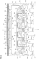
- FIG. 1 is a plan view illustrating the hood structure for a vehicle.
- Fig. 2 is a plan view of a front-half portion of the hood structure illustrated in a state where an outer panel is removed.
- Fig. 3 is a perspective view of the hood structure for a vehicle illustrated in the state where the outer panel is removed.
- Fig. 4 is an enlarged plan view of a main section in Fig. 2 .
- Fig. 5 is an enlarged plan view of a main section of an inner panel in a state where a stiffener is removed from Fig. 4 .
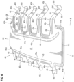
- Fig. 6 is a perspective view of the stiffener.
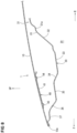
- Fig. 7 is a cross-sectional view that is taken along arrow A-A Fig. 2 .
- Fig. 8 is a cross-sectional view that is taken along arrow B-B in Fig. 2 .
- a hood structure 1 for a vehicle includes an outer panel 10 (in detail, a hood outer panel) that defines external appearance, an inner panel 30 (in detail, a hood inner panel) that is provided on a prime mover chamber 20 side of the outer panel 10 (or below the outer panel 10), and a stiffener 40 that is provided to a front portion of the inner panel 30.
- the prime mover chamber 20 is set as an engine compartment. In the case where the vehicle is an electric car, the prime mover chamber 20 is set as a motor chamber.
- the outer panel 10 and the inner panel 30 described above may be integrally formed by hemming a peripheral edge of the outer panel 10. It is configured that both of these panels 10, 30 cover an upper portion of the prime mover chamber 20 from above in an openable/closable manner. In this embodiment, it is configured that a front side of a hood is opened/closed with a rear end side of the hood being a fulcrum.
- the above-described inner panel 30 has: an upper surface section 31 that is located on a center side of the outer panel 10, that is, a center side in a vehicle front-rear direction and a vehicle width direction of the outer panel 10; a coupling surface section 32 that extends downward from a ridgeline X1 located at a peripheral edge of the upper surface section 31; and a lower surface section 33 that extends to an edge 10a side of the outer panel 10 from a peripheral edge end of the coupling surface section 32 (see Fig. 7 ).
- the upper surface section 31 of the inner panel 30 may include: a front side section 31a that extends in the vehicle width direction in a front portion of the upper surface section 31; and a rear side section 31b that extends in the vehicle width direction in a rear portion of the upper surface section 31.
- the upper surface section 31 may include right and left lateral side sections 31c, 31d that respectively couple right and left ends in the vehicle width direction of the front side section 31a and the rear side section 31b in the vehicle front-rear direction (see Fig. 2 and Fig. 3 ).
- the above upper surface section 31 may include plural beam sections 31e that couple the front side section 31a and the rear side section 31b in the vehicle front-rear direction at spaced intervals in the vehicle width direction (see Fig. 2 and Fig. 3 ).
- An upper surface of each of these beam sections 31e and the right and left lateral side sections 31c, 31d is fixed to a lower surface of the outer panel 10 by an adhesive, which is not illustrated.
- a coupling piece section 31f and a coupling piece section 31g may be provided.
- the coupling piece section 31f couples the beam section 31e, which is located on a far-left side in the vehicle width direction of the plural beam sections 31e, and the beam section 31e, which is adjacent to such a beam section 31e, in the vehicle width direction.
- the coupling piece section 31g couples the beam section 31e, which is located on a far-right side in the vehicle width direction of the plural beam sections 31e, and the beam section 31e, which is adjacent to such a beam section 31e, in the vehicle width direction.
- the above-described coupling surface section 32 may be provided with plural openings 32a for a lightweight purpose.
- the plural openings 32a are provided in an area that includes the coupling surface section 32 and the front side section 31a of the upper surface section 31, and are provided at spaced intervals in the vehicle width direction.
- the inner panel 30 may have a stiffener support surface section 37 via a front-side coupling surface section 34, an intermediate surface section 35, and an inclined surface section 36 from a peripheral edge end of the above-described lower surface section 33.
- the stiffener support surface section 37 may extend to the edge 10a side of the outer panel 10.
- the above-described coupling surface section 32 is inclined in a front-low, rear-high state where the coupling surface section 32 is inclined downward to the front and upward to the rear.
- the above-described front-side coupling surface section 34 and the inclined surface section 36 described above may be inclined in a front-high, rear-low state where the above-described front-side coupling surface section 34 and the inclined surface section 36 are inclined upward to the front and downward to the rear (see Fig. 7 and Fig. 8 ).
- each of the front side section 31a of the upper surface section 31 described above, the intermediate surface section 35, and the stiffener support surface section 37 may be formed to be parallel with or substantially parallel with a portion at an opposing position in the lower surface of the outer panel 10 (see Fig. 7 and Fig. 8 ).
- the above-described stiffener 40 has: a reinforcing surface section 41 that is joined to the lower surface of the outer panel 10 e.g. by using the adhesive; and a rear-side fixed section 42 that extends rearward from this reinforcing surface section 41.
- the above-described rear-side fixed section 42 is fixed to the vicinity (at a proximity position) of the above-described ridgeline X1.
- the stiffener 40 is fixed to the vicinity of the ridgeline X1.
- it is configured to improve support rigidity of the outer panel 10 and thereby prevent deformation of the outer panel 10, for example, when a user touches the outer panel 10, or the like, to apply a downward load to the outer panel 10.
- an impact load when applied during pedestrian protection, it is configured to deform the ridgeline X1 via the stiffener 40, so as to further increase an energy absorption amount not only through energy absorption achieved by the deformation of the stiffener 40 but also by deformation of the inner panel 30.
- it is configured to simultaneously secure outer panel rigidity of the front portion of the outer panel 10 and pedestrian protection performance at a high level.
- the above-described reinforcing surface section 41 may be formed in a substantially rectangular shape that is long in the vehicle width direction.
- beads 43, 44 each of which is projected downward, may be integrally formed in a front portion and a rear portion of the reinforcing surface section 41, respectively.
- Each of these beads 43, 44 is designed to improve rigidity of the reinforcing surface section 41.
- folded sections 41a, 41b, 41c, 41d may be integrally formed on a front side, a rear side, and right and left lateral sides of the reinforcing surface section 41 that may be formed in the substantially rectangular shape and formed to be laterally elongated in the plan view.
- Each of these folded sections 41a, 41b, 41c, 41d is designed to secure required rigidity of the reinforcing surface section 41.
- the plural rear-side fixed sections 42 described above may be provided at spaced intervals in the vehicle width direction.
- the five rear-side fixed sections 42 are provided.
- the above-described rear-side fixed section 42 may includes: a rear extending section 42a that extends rearward from the reinforcing surface section 41; a downward extending section 42c that extends downward (in detail, a rear and down direction) from a rear-side fixed section of this rear extending section 42a via a bent section 42b; and an attachment piece section 42d that extends rearward and upward from a lower end of the downward extending section 42c.
- the rear-side fixed section 42 which includes these elements 42a, 42b, 42c, 42d, is formed to extend in the front-rear direction in the plan view.
- a bead 42e is formed to be projected downward from the upper surface. In this way, it is configured to improve rigidity of the rear extending section 42a with this bead 42e.
- a bead 42f may be formed in an inverted triangular shape in a side view.
- the bead 42f couples a lower portion of the downward extending section 42c, which is inclined in a front-high, rear-low state, and a front portion of the attachment piece section 42d, which is inclined in a front-low, rear-high state. In this way, it is configured to prevent deformation between the elements 42c, 42d with this bead 42f so as to secure load transmission performance.
- a substantially half portion on the front side is formed in an inverted U-shape that is opened downward in a cross section in the vehicle width direction.
- this inverted U-shape structure it is configured to improve the load transmission performance to the downward extending section 42c during the pedestrian protection.
- a front-side fixed section 45 is provided to extend forward from the reinforcing surface section 41.
- This front-side fixed section 45 may include: a forward extending section 45a that extends forward from the reinforcing surface section 41; a coupling section 45b that extends downward from a front end of the forward extending section 45a; and an attachment piece section 45c that extends forward from a lower end of the coupling section 45b.
- the forward extending section 45a, the coupling section 45b, and attachment piece section 45c may be coupled in a substantially Z-shape in the side view.
- a vertical distance L2 between the attachment piece section 42d of the above-described rear-side fixed section 42 and the reinforcing surface section 41 may be set to be longer than a vertical distance L1 between the attachment piece section 45c of the front-side fixed section 45 and the reinforcing surface section 41. That is, it is formed to satisfy a relational expression L2 > L1.
- the plural front-side fixed sections 45 each of which extends forward from the reinforcing surface section 41, may be provided at spaced intervals in the vehicle width direction.
- the five front-side fixed sections 45 are provided.
- the above-described rear-side fixed sections 42 may be respectively provided at the same positions as the front-side fixed sections 45 in the vehicle width direction.
- each of the rear-side fixed sections 42 is provided at a position to be aligned with the respective front-side fixed section 45 in the front-rear direction via the reinforcing surface section 41.
- the plural rear-side fixed sections 42 and the plural front-side fixed sections 45 are present at the same positions in the vehicle width direction. In this way, it is configured to reliably transmit the load to the rear-side fixed sections 42 during the pedestrian protection, so as to concentrate stress on the rear-side fixed sections 42.
- the above-described reinforcing surface section 41 is joined to the inner panel 30 via the bent section 42b in the rear portion of the reinforcing surface section 41.
- the reinforcing surface section 41 is joined to the vicinity of the ridgeline X1 of the inner panel 30, that is, the proximity position of the ridgeline X1 via the rear extending section 42a, the bent section 42b, the downward extending section 42c, and the attachment piece section 42d of the rear-side fixed section 42.
- the reinforcing surface section 41 is provided to the inner panel portion, rigidity of which is improved by the ridgeline X1, via the bent section 42b.
- it is configured to prevent the deformation of the reinforcing surface section 41 and the outer panel 10 during the normal time.
- the plural rear-side fixed sections 42 described above are separated from each other in the vehicle width direction, and are formed such that the positions of the bent sections 42b in the front-rear direction in these plural rear-side fixed sections 42 match or substantially match each other in the vehicle width direction.
- the above-described inner panel 30 is formed with a joint seat surface 38, to which the rear-side fixed section 42, in detail, the attachment piece section 42d of the rear-side fixed section 42 is joined, in a continuous manner with the ridgeline X1 of the inner panel 30.
- the joint seating surface 38 is connected to the ridgeline X1.
- it is configured to reliably transmit the load to the ridgeline X1 via the joint seat surface 38 during the pedestrian protection.
- it is configured to reliably transmit the load to the ridgeline X1 by making the joint seat surface 38 continue with the ridgeline X1.
- the above-described ridgeline X1 may have an interrupted section 39 that is interrupted at a position of the joint seat surface 38.
- the joint seat surface 38 is provided on a virtual extension line of the ridgeline X1 in the interrupted section 39 of the ridgeline X1.
- the load can further reliably be transmitted from the joint seat surface 38 to the ridgeline X1.
- it is configured to deform the ridgeline X1 via the stiffener 40 during the pedestrian protection, secure the energy absorption by the deformation of the inner panel 30 in addition to the energy absorption by the deformation of the stiffener 40, and thereby increase the energy absorption amount.
- the attachment piece section 42d in the rear-side fixed section 42 illustrated in Fig. 4 may be welded to the joint seat surface 38 at a spot-welding point SW1 that is a spot-welded portion located substantially at a center of the joint seat surface 38 illustrated in Fig. 5 .
- attachment piece section 45c of the front-side fixed section 45 illustrated in Fig. 4 may be welded to the stiffener support surface section 37 at a spot-welding point SW2 that is located in the stiffener support surface section 37 illustrated in Fig. 5 .
- the spot-welding point SW2 located on the front side and the spot-welding point SW1 located on the rear side are provided at the substantially same position in the vehicle width direction.
- Fig. 3 illustrates a hinge bracket 50 that may be provided to each of right and left rear portions of the inner panel 30.
- Fig. 5 and Fig. 7 each illustrate a center bracket 51 that may be provided at a center in the vehicle width direction of the front portion of the inner panel 30.
- Fig. 2 to Fig. 5 each illustrate a side bracket 52 that is provided close to each of right and left outer sides in the vehicle width direction in the front portion of the inner panel 30.
- an arrow F indicates a vehicle front direction
- an arrow R indicates a vehicle rear direction
- an arrow LE indicates the outer left side in the vehicle width direction
- an arrow RI indicates the outer right side in the vehicle width direction
- an arrow UP indicates a vehicle up direction.
- the hood structure for a vehicle includes: the outer panel 10 that defines the external appearance; the inner panel 30 that is provided on the prime mover chamber 20 side of the outer panel 10; and the stiffener 40 that is provided in the front portion of the inner panel 30, the inner panel 30 has: the upper surface section 31 that is provided on the center side of the outer panel 10; the coupling surface section 32 that extends downward from the ridgeline X1 located at the peripheral edge of the upper surface section 31; and the lower surface section 33 that extends from the peripheral edge end of the coupling surface section 32 to the edge 10a side of the outer panel 10, the stiffener 40 has: the reinforcing surface section 41 that is joined to the outer panel 10; and the rear-side fixed section 42 that extends rearward from the reinforcing surface section 41, and the rear-side fixed section 42 is fixed to the vicinity of the ridgeline X1 (see Fig. 4 and Fig. 7 ).
- the stiffener 40 is fixed to the vicinity of the ridgeline X1.
- the support rigidity of the outer panel 10 is improved, and the deformation of the outer panel 10 can be prevented.
- the ridgeline X1 can be deformed via the stiffener 40.
- Such a hood structure for a vehicle also includes the front-side fixed section 45 that extends forward from the reinforcing surface section 41.
- the hood structure for a vehicle is formed such that the vertical distance L2 between the rear-side fixed section 42 and the reinforcing surface section 41 is longer than the vertical distance L1 between the front-side fixed section 45 and the reinforcing surface section 41 (see Fig. 7 ).
- the rear-side fixed section 42 is provided at the same position as the front-side fixed section 45 in the vehicle width direction (see Fig. 2 and Fig. 4 ).
- the rear-side fixed section 42 and the front-side fixed section 45 are present at the same position in the vehicle width direction. Therefore, it is possible to reliably transmit the load to the rear-side fixed section 42 during the pedestrian protection, so as to concentrate the stress on the rear-side fixed section 42.
- the reinforcing surface section 41 is joined to the inner panel 30 via the bent section 42b in the rear portion of the reinforcing surface section 41 (see Fig. 6 and Fig. 7 ).
- the reinforcing surface section 41 is provided to the inner panel portion, the rigidity of which is improved by the ridgeline X1, via the bent section 42b. Therefore, it is possible to prevent the deformation of the reinforcing surface section 41 and the outer panel 10 during the normal time.
- the plural rear-side fixed sections 42 are separated from each other in the vehicle width direction and are formed such that the positions of the bent sections 42b in the front-rear direction in these plural rear-side fixed sections 42 match each other in the vehicle width direction (see Fig. 4 ).
- the load is transmitted to the rear-side fixed sections 42 (in detail, see the attachment piece sections 42d) via the bent sections 42b all at once.
- the load is transmitted to the rear-side fixed sections 42 (in detail, see the attachment piece sections 42d) via the bent sections 42b all at once.
- the joint seat surface 38, to which the rear-side fixed section 42 is joined, is formed to continue with the ridgeline X1 of the inner panel 30 (see Fig. 5 ).
- the joint seating surface 38 is connected to the ridgeline X1.
- the joint seating surface 38 is connected to the ridgeline X1.
- the ridgeline X1 has the interrupted section 39 that is interrupted at the position of the joint seat surface 38, and the joint seat surface 38 is provided on the virtual extension line of the ridgeline X1 in the interrupted section 39 of the ridgeline X1 (see Fig. 5 ).
- the load can further reliably be transmitted from the joint seat surface 38 to the ridgeline X1. Therefore, it is possible to deform the ridgeline X1 via the stiffener 40 during the pedestrian protection, secure the energy absorption by the deformation of the inner panel 30 in addition to the energy absorption by the deformation of the stiffener 40, and thereby increase the energy absorption amount.
- the formed number of each of the rear-side fixed section 42 and the front-side fixed section 45 may be plural other than five.
- the present invention is useful for the hood structure for a vehicle, the hood structure including the outer panel that defines the external appearance, the inner panel that is provided on the prime mover chamber side of the outer panel, and the stiffener that is provided to the front portion of the inner panel.
Landscapes
- Engineering & Computer Science (AREA)
- Chemical & Material Sciences (AREA)
- Combustion & Propulsion (AREA)
- Transportation (AREA)
- Mechanical Engineering (AREA)
- Superstructure Of Vehicle (AREA)
Abstract
Description
- The present invention relates to a hood structure for a vehicle, the hood structure including an outer panel that defines external appearance, an inner panel that is provided on a prime mover chamber side of the outer panel, and a stiffener that is provided to a front portion of the inner panel.
- Conventionally, the following hood structure for a vehicle has been known. The hood structure includes an outer panel (in detail, a hood outer panel) that defines external appearance, an inner panel (in detail, a hood inner panel) that is provided on a prime mover chamber side, such as an engine compartment side, of the outer panel, and a stiffener that is provided to a front portion of the inner panel (Patent document 1).
- The above-described inner panel includes: an upper surface section that is located on a center side of the outer panel; and a coupling surface section that extends downward from a peripheral edge end of this upper surface section and is inclined in a front-low, rear-high state.
- Then, the stiffener is fixed to the coupling surface section of the above-described inner panel, so as to secure outer plate rigidity by the stiffener. Meanwhile, during pedestrian protection, an upper surface of the stiffener moves downward to absorb energy when receiving an impact load from above. In this way, it is configured to reduce a reaction force generated to a colliding object.
- However, further improvement is requested for pedestrian protection performance of the hood front portion in a vehicle with a high height, for example. Therefore, there is room for further improvement in the conventional structure disclosed in
above Patent document 1. - [Patent document 1]
JP-A-2020-128169 - In view of the above, the present invention has a purpose of providing a hood structure for a vehicle capable of simultaneously securing outer panel rigidity of a front portion of an outer panel and securing pedestrian protection performance at a high level.
- The present invention provides a hood structure for a vehicle, and the hood structure includes: an outer panel that defines external appearance; an inner panel that is provided on a prime mover chamber side of the outer panel (or below the outer panel); and a stiffener that is provided in a front portion of the inner panel. The inner panel has: an upper surface section that is located on a center side of the outer panel; a coupling surface section that extends downward from a ridgeline located at a peripheral edge of the upper surface section; and a lower surface section that extends from a peripheral edge end of the coupling surface section to an edge side of the outer panel. The stiffener has: a reinforcing surface section that is joined to the outer panel; and a rear-side fixed section that extends rearward from the reinforcing surface section. The rear-side fixed section is fixed to the vicinity of the ridgeline.
- In a case of an engine-driven vehicle, the above-described prime mover chamber is a compartment or an engine compartment. In a case of an electric car, the above-described prime mover chamber is a compartment or a motor chamber.
- According to the present invention, during normal time (non-collision time), the stiffener is fixed to the vicinity of the ridgeline. Thus, it is possible to improve support rigidity of the outer panel and thereby prevent deformation of the outer panel, for example, when a user touches the outer panel, or the like, to apply a downward load to the outer panel.
- Meanwhile, when an impact load is applied during pedestrian protection, the ridgeline can be deformed via the stiffener. Thus, it is possible to increase an energy absorption amount not only through energy absorption achieved by deformation of the stiffener but also by deformation of the inner panel.
- That is, it is possible to simultaneously secure outer panel rigidity of a front portion of the outer panel and pedestrian protection performance at a high level.
- An aspect of the present invention may include a front-side fixed section that extends forward from the reinforcing surface section. It may be formed such that a vertical distance between the rear-side fixed section and the reinforcing surface section is longer than a vertical distance between the front-side fixed section and the reinforcing surface section.
- According to this aspect, during the pedestrian protection, moment that presses the rear-side fixed section downward and rearward is generated with a front side on the reinforcing surface section side of the rear-side fixed section being an origin, and a rotational force is generated by this moment. Thus, it is possible to promote the deformation of the inner panel by pressing the inner panel downward. Therefore, it is possible to increase the energy absorption amount.
- As an aspect of the present invention, the rear-side fixed section may be provided at the same position as the front-side fixed section in a vehicle width direction.
- According to this aspect, the rear-side fixed section and the front-side fixed section are present at the same position in the vehicle width direction. Therefore, it is possible to reliably transmit the load to the rear-side fixed section during the pedestrian protection, so as to concentrate stress on the rear-side fixed section.
- As an aspect of the present invention, the reinforcing surface section may be joined to the inner panel via a bent section in a rear portion of the reinforcing surface section.
- According to this aspect, the reinforcing surface section is provided to an inner panel portion, rigidity of which is improved by the ridgeline, via the bent section. Therefore, it is possible to prevent the deformation of the reinforcing surface section and the outer panel during the normal time.
- As an aspect of the present invention, plural rear-side fixed sections may be provided. The plural rear-side fixed sections may be separated from each other in the vehicle width direction, and may be formed such that positions of the bent sections in the plural rear-side fixed sections match each other in a front-rear direction.
- According to this aspect, during the pedestrian protection, it is possible to transmit the load to the rear-side fixed sections via the bent sections all at once, so as to concentrate the stress on the vicinity of the ridgeline. In this way, it is possible to increase the energy absorption amount by stably deforming the inner panel downward.
- As an aspect of the present invention, a joint seat surface, to which the rear-side fixed section is joined, may be formed to continue with the ridgeline of the inner panel.
- According to this aspect, the joint seating surface is connected to the ridgeline. Thus, it is possible to reliably transmit the load to the ridgeline via the joint seat surface during the pedestrian protection. In other words, it is possible to reliably transmit the load to the ridgeline by making the joint seat surface continue with the ridgeline.
- As an aspect of the present invention, the ridgeline may have an interrupted section that is interrupted at a position of the joint seat surface, and the joint seat surface may be provided on a virtual extension line of the ridgeline in the interrupted section of the ridgeline.
- According to this aspect, the load can further reliably be transmitted from the joint seat surface to the ridgeline. Thus, it is possible to deform the ridgeline via the stiffener during the pedestrian protection, secure the energy absorption by the deformation of the inner panel in addition to the energy absorption by the deformation of the stiffener, and thereby increase the energy absorption amount.
- The present invention has such an effect that it is possible to simultaneously secure the outer panel rigidity of the front portion of the outer panel and the pedestrian protection performance at the high level.
-
- [
Fig. 1] Fig. 1 is a plan view of a hood structure for a vehicle. - [
Fig. 2] Fig. 2 is a plan view of a front-half portion of the hood structure illustrated with an outer panel being removed. - [
Fig. 3] Fig. 3 is a perspective view of the hood structure for a vehicle illustrated with the outer panel being removed. - [
Fig. 4] Fig. 4 is an enlarged plan view of a main section inFig. 2 . - [
Fig. 5] Fig. 5 is an enlarged plan view of a main section of an inner panel with a stiffener being removed fromFig. 4 . - [
Fig. 6] Fig. 6 is a perspective view of the stiffener. - [
Fig. 7] Fig. 7 is a cross-sectional view that is taken along arrow A-A inFig. 2 with the outer panel. - [
Fig. 8] Fig. 8 is a cross-sectional view that is taken along arrow B-B inFig. 2 with the outer panel. - A purpose of simultaneously securing the outer panel rigidity of the front portion of the outer panel and securing the pedestrian protection performance at the high level is achieved particularly by a configuration that includes: an outer panel defining external appearance; an inner panel provided on a prime mover chamber side of the outer panel; and a stiffener provided in a front portion of the inner panel, in which the inner panel has: an upper surface section located on a center side of the outer panel; a coupling surface section extending downward from a ridgeline located at a peripheral edge of the upper surface section; and a lower surface section extending from a peripheral edge end of the coupling surface section to an edge side of the outer panel, in which the stiffener has: a reinforcing surface section joined to the outer panel; and a rear-side fixed section extending rearward from the reinforcing surface section, and in which the rear-side fixed section is fixed to the vicinity of the ridgeline.
- A detailed description will hereinafter be made on an embodiment of the present invention with reference to the drawings. All of the features as shown in the drawings may not necessarily be essential.
- A hood structure for a vehicle or an automobile is illustrated in the drawings.
Fig. 1 is a plan view illustrating the hood structure for a vehicle.Fig. 2 is a plan view of a front-half portion of the hood structure illustrated in a state where an outer panel is removed.Fig. 3 is a perspective view of the hood structure for a vehicle illustrated in the state where the outer panel is removed. -
Fig. 4 is an enlarged plan view of a main section inFig. 2 .Fig. 5 is an enlarged plan view of a main section of an inner panel in a state where a stiffener is removed fromFig. 4 .Fig. 6 is a perspective view of the stiffener.Fig. 7 is a cross-sectional view that is taken along arrow A-AFig. 2 .Fig. 8 is a cross-sectional view that is taken along arrow B-B inFig. 2 . - As illustrated in
Fig. 1 ,Fig. 7 , andFig. 8 , ahood structure 1 for a vehicle includes an outer panel 10 (in detail, a hood outer panel) that defines external appearance, an inner panel 30 (in detail, a hood inner panel) that is provided on aprime mover chamber 20 side of the outer panel 10 (or below the outer panel 10), and astiffener 40 that is provided to a front portion of theinner panel 30. - In the case where a vehicle is an engine-driven vehicle, the
prime mover chamber 20 is set as an engine compartment. In the case where the vehicle is an electric car, theprime mover chamber 20 is set as a motor chamber. - The
outer panel 10 and theinner panel 30 described above may be integrally formed by hemming a peripheral edge of theouter panel 10. It is configured that both of thesepanels prime mover chamber 20 from above in an openable/closable manner. In this embodiment, it is configured that a front side of a hood is opened/closed with a rear end side of the hood being a fulcrum. - The above-described
inner panel 30 has: anupper surface section 31 that is located on a center side of theouter panel 10, that is, a center side in a vehicle front-rear direction and a vehicle width direction of theouter panel 10; acoupling surface section 32 that extends downward from a ridgeline X1 located at a peripheral edge of theupper surface section 31; and alower surface section 33 that extends to anedge 10a side of theouter panel 10 from a peripheral edge end of the coupling surface section 32 (seeFig. 7 ). - As illustrated in
Fig. 3 , theupper surface section 31 of theinner panel 30 may include: afront side section 31a that extends in the vehicle width direction in a front portion of theupper surface section 31; and arear side section 31b that extends in the vehicle width direction in a rear portion of theupper surface section 31. - In addition, the
upper surface section 31 may include right and leftlateral side sections front side section 31a and therear side section 31b in the vehicle front-rear direction (seeFig. 2 andFig. 3 ). - Furthermore, the above
upper surface section 31 may includeplural beam sections 31e that couple thefront side section 31a and therear side section 31b in the vehicle front-rear direction at spaced intervals in the vehicle width direction (seeFig. 2 andFig. 3 ). An upper surface of each of thesebeam sections 31e and the right and leftlateral side sections outer panel 10 by an adhesive, which is not illustrated. - Moreover, a
coupling piece section 31f and acoupling piece section 31g may be provided. Thecoupling piece section 31f couples thebeam section 31e, which is located on a far-left side in the vehicle width direction of theplural beam sections 31e, and thebeam section 31e, which is adjacent to such abeam section 31e, in the vehicle width direction. Thecoupling piece section 31g couples thebeam section 31e, which is located on a far-right side in the vehicle width direction of theplural beam sections 31e, and thebeam section 31e, which is adjacent to such abeam section 31e, in the vehicle width direction. - Meanwhile, as illustrated in
Fig. 3 ,Fig. 4 , andFig. 5 , the above-describedcoupling surface section 32 may be provided withplural openings 32a for a lightweight purpose. Theplural openings 32a are provided in an area that includes thecoupling surface section 32 and thefront side section 31a of theupper surface section 31, and are provided at spaced intervals in the vehicle width direction. - As illustrated in
Fig. 7 andFig. 8 , theinner panel 30 may have a stiffenersupport surface section 37 via a front-sidecoupling surface section 34, anintermediate surface section 35, and aninclined surface section 36 from a peripheral edge end of the above-describedlower surface section 33. The stiffenersupport surface section 37 may extend to theedge 10a side of theouter panel 10. - As illustrated in
Fig. 7 andFig. 8 , at a center position in the vehicle width direction of the inner panel 30 (a position in the cross section that is taken along arrow A-A) and an offset position near such a position (a position in the cross section that is taken along arrow B-B), the above-describedcoupling surface section 32 is inclined in a front-low, rear-high state where thecoupling surface section 32 is inclined downward to the front and upward to the rear. - Meanwhile, in the center position in the vehicle width direction (the position in the cross section that is taken along arrow A-A) and the offset position near such a position (a position in the cross section that is taken along arrow B-B), the above-described front-side
coupling surface section 34 and theinclined surface section 36 described above may be inclined in a front-high, rear-low state where the above-described front-sidecoupling surface section 34 and theinclined surface section 36 are inclined upward to the front and downward to the rear (seeFig. 7 andFig. 8 ). - In addition, each of the
front side section 31a of theupper surface section 31 described above, theintermediate surface section 35, and the stiffenersupport surface section 37 may be formed to be parallel with or substantially parallel with a portion at an opposing position in the lower surface of the outer panel 10 (seeFig. 7 andFig. 8 ). - As illustrated in
Fig. 4 ,Fig. 6 , andFig. 7 , the above-describedstiffener 40 has: a reinforcingsurface section 41 that is joined to the lower surface of theouter panel 10 e.g. by using the adhesive; and a rear-side fixedsection 42 that extends rearward from this reinforcingsurface section 41. The above-described rear-side fixedsection 42 is fixed to the vicinity (at a proximity position) of the above-described ridgeline X1. - In this way, during normal time (non-collision time), the
stiffener 40 is fixed to the vicinity of the ridgeline X1. Thus, it is configured to improve support rigidity of theouter panel 10 and thereby prevent deformation of theouter panel 10, for example, when a user touches theouter panel 10, or the like, to apply a downward load to theouter panel 10. - Meanwhile, when an impact load is applied during pedestrian protection, it is configured to deform the ridgeline X1 via the
stiffener 40, so as to further increase an energy absorption amount not only through energy absorption achieved by the deformation of thestiffener 40 but also by deformation of theinner panel 30. - That is, it is configured to simultaneously secure outer panel rigidity of the front portion of the
outer panel 10 and pedestrian protection performance at a high level. - In detail, in a plan view as illustrated in
Fig. 4 , the above-described reinforcingsurface section 41 may be formed in a substantially rectangular shape that is long in the vehicle width direction. - As illustrated in
Fig, 4 ,Fig. 6 , andFig. 7 ,beads surface section 41, respectively. Each of thesebeads surface section 41. - As illustrated in
Fig. 4 andFig. 6 , foldedsections surface section 41 that may be formed in the substantially rectangular shape and formed to be laterally elongated in the plan view. Each of these foldedsections surface section 41. - In addition, as illustrated in
Fig. 4 andFig. 6 , the plural rear-side fixedsections 42 described above may be provided at spaced intervals in the vehicle width direction. - In this embodiment, the five rear-side fixed
sections 42 are provided. As illustrated inFig. 6 andFig. 7 , the above-described rear-side fixedsection 42 may includes: arear extending section 42a that extends rearward from the reinforcingsurface section 41; a downward extendingsection 42c that extends downward (in detail, a rear and down direction) from a rear-side fixed section of thisrear extending section 42a via abent section 42b; and anattachment piece section 42d that extends rearward and upward from a lower end of the downward extendingsection 42c. The rear-side fixedsection 42, which includes theseelements - As illustrated in
Fig. 6 , on an upper surface of the above-describedrear extending section 42a, abead 42e is formed to be projected downward from the upper surface. In this way, it is configured to improve rigidity of therear extending section 42a with thisbead 42e. - In addition, as illustrated in
Fig. 6 , abead 42f may be formed in an inverted triangular shape in a side view. Thebead 42f couples a lower portion of the downward extendingsection 42c, which is inclined in a front-high, rear-low state, and a front portion of theattachment piece section 42d, which is inclined in a front-low, rear-high state. In this way, it is configured to prevent deformation between theelements bead 42f so as to secure load transmission performance. - Here, in the front-rear direction of the above-described
rear extending section 42a, a substantially half portion on the front side is formed in an inverted U-shape that is opened downward in a cross section in the vehicle width direction. With this inverted U-shape structure, it is configured to improve the load transmission performance to the downward extendingsection 42c during the pedestrian protection. - As illustrated in
Fig. 4 andFig. 6 , a front-side fixedsection 45 is provided to extend forward from the reinforcingsurface section 41. - This front-side fixed
section 45 may include: a forward extendingsection 45a that extends forward from the reinforcingsurface section 41; acoupling section 45b that extends downward from a front end of theforward extending section 45a; and anattachment piece section 45c that extends forward from a lower end of thecoupling section 45b. In the front-side fixedsection 45, the forward extendingsection 45a, thecoupling section 45b, andattachment piece section 45c may be coupled in a substantially Z-shape in the side view. - As illustrated in
Fig. 7 , a vertical distance L2 between theattachment piece section 42d of the above-described rear-side fixedsection 42 and the reinforcingsurface section 41 may be set to be longer than a vertical distance L1 between theattachment piece section 45c of the front-side fixedsection 45 and the reinforcingsurface section 41. That is, it is formed to satisfy a relational expression L2 > L1. - In detail, it is formed such that the vertical distance L2 between the
elements outer panel 10 opposing a rear end portion of the reinforcingsurface section 41, is longer than the vertical distance L1 between theelements outer panel 10 opposing a front end portion of the reinforcingsurface section 41. - In this way, it is configured that, during the pedestrian protection, moment that presses the rear-side fixed
section 42 downward and rearward is generated with a front side on the reinforcingsurface section 41 side of the rear-side fixedsection 42 being an origin, a rotational force is generated by this moment to press and deform theinner panel 30 downward, and the energy absorption amount is thereby improved. - As illustrated in
Fig. 2 andFig. 4 , the plural front-side fixedsections 45, each of which extends forward from the reinforcingsurface section 41, may be provided at spaced intervals in the vehicle width direction. - In this embodiment, the five front-side fixed
sections 45 are provided. As illustrated inFig. 2 andFig. 4 , the above-described rear-side fixedsections 42 may be respectively provided at the same positions as the front-side fixedsections 45 in the vehicle width direction. In other words, each of the rear-side fixedsections 42 is provided at a position to be aligned with the respective front-side fixedsection 45 in the front-rear direction via the reinforcingsurface section 41. - Just as described, the plural rear-side fixed
sections 42 and the plural front-side fixedsections 45 are present at the same positions in the vehicle width direction. In this way, it is configured to reliably transmit the load to the rear-side fixedsections 42 during the pedestrian protection, so as to concentrate stress on the rear-side fixedsections 42. - As illustrated in
Fig. 7 , the above-described reinforcingsurface section 41 is joined to theinner panel 30 via thebent section 42b in the rear portion of the reinforcingsurface section 41. In detail, the reinforcingsurface section 41 is joined to the vicinity of the ridgeline X1 of theinner panel 30, that is, the proximity position of the ridgeline X1 via therear extending section 42a, thebent section 42b, the downward extendingsection 42c, and theattachment piece section 42d of the rear-side fixedsection 42. - In this way, the reinforcing
surface section 41 is provided to the inner panel portion, rigidity of which is improved by the ridgeline X1, via thebent section 42b. Thus, it is configured to prevent the deformation of the reinforcingsurface section 41 and theouter panel 10 during the normal time. - As illustrated in
Fig. 4 , the plural rear-side fixedsections 42 described above are separated from each other in the vehicle width direction, and are formed such that the positions of thebent sections 42b in the front-rear direction in these plural rear-side fixedsections 42 match or substantially match each other in the vehicle width direction. - In this way, it is configured that, during the pedestrian protection, the load is transmitted to the
attachment piece sections 42d of the rear-side fixedsections 42 via thebent sections 42b all at once to concentrate the stress on the vicinity of the ridgeline X1, theinner panel 30 is consequently deformed downward, and the energy absorption amount is thereby increased. - As illustrated in
Fig. 5 , the above-describedinner panel 30 is formed with ajoint seat surface 38, to which the rear-side fixedsection 42, in detail, theattachment piece section 42d of the rear-side fixedsection 42 is joined, in a continuous manner with the ridgeline X1 of theinner panel 30. - In this way, the
joint seating surface 38 is connected to the ridgeline X1. Thus, it is configured to reliably transmit the load to the ridgeline X1 via thejoint seat surface 38 during the pedestrian protection. In other words, it is configured to reliably transmit the load to the ridgeline X1 by making thejoint seat surface 38 continue with the ridgeline X1. - In detail, as illustrated in
Fig. 5 , the above-described ridgeline X1 may have an interruptedsection 39 that is interrupted at a position of thejoint seat surface 38. Thejoint seat surface 38 is provided on a virtual extension line of the ridgeline X1 in the interruptedsection 39 of the ridgeline X1. - In this way, the load can further reliably be transmitted from the
joint seat surface 38 to the ridgeline X1. Thus, it is configured to deform the ridgeline X1 via thestiffener 40 during the pedestrian protection, secure the energy absorption by the deformation of theinner panel 30 in addition to the energy absorption by the deformation of thestiffener 40, and thereby increase the energy absorption amount. - Here, the
attachment piece section 42d in the rear-side fixedsection 42 illustrated inFig. 4 may be welded to thejoint seat surface 38 at a spot-welding point SW1 that is a spot-welded portion located substantially at a center of thejoint seat surface 38 illustrated inFig. 5 . - Meanwhile, the
attachment piece section 45c of the front-side fixedsection 45 illustrated inFig. 4 may be welded to the stiffenersupport surface section 37 at a spot-welding point SW2 that is located in the stiffenersupport surface section 37 illustrated inFig. 5 . - The spot-welding point SW2 located on the front side and the spot-welding point SW1 located on the rear side are provided at the substantially same position in the vehicle width direction.
-
Fig. 3 illustrates ahinge bracket 50 that may be provided to each of right and left rear portions of theinner panel 30.Fig. 5 andFig. 7 each illustrate acenter bracket 51 that may be provided at a center in the vehicle width direction of the front portion of theinner panel 30. Furthermore,Fig. 2 to Fig. 5 each illustrate aside bracket 52 that is provided close to each of right and left outer sides in the vehicle width direction in the front portion of theinner panel 30. - In the drawings, an arrow F indicates a vehicle front direction, an arrow R indicates a vehicle rear direction, an arrow LE indicates the outer left side in the vehicle width direction, an arrow RI indicates the outer right side in the vehicle width direction, and an arrow UP indicates a vehicle up direction.
- As it has been described so far, the hood structure for a vehicle according to this embodiment includes: the
outer panel 10 that defines the external appearance; theinner panel 30 that is provided on theprime mover chamber 20 side of theouter panel 10; and thestiffener 40 that is provided in the front portion of theinner panel 30, theinner panel 30 has: theupper surface section 31 that is provided on the center side of theouter panel 10; thecoupling surface section 32 that extends downward from the ridgeline X1 located at the peripheral edge of theupper surface section 31; and thelower surface section 33 that extends from the peripheral edge end of thecoupling surface section 32 to theedge 10a side of theouter panel 10, thestiffener 40 has: the reinforcingsurface section 41 that is joined to theouter panel 10; and the rear-side fixedsection 42 that extends rearward from the reinforcingsurface section 41, and the rear-side fixedsection 42 is fixed to the vicinity of the ridgeline X1 (seeFig. 4 andFig. 7 ). - According to such a hood structure for a vehicle, during the normal time (the non-collision time), the
stiffener 40 is fixed to the vicinity of the ridgeline X1. Thus, for example, when the user touches theouter panel 10, or the like, to apply the downward load to theouter panel 10, the support rigidity of theouter panel 10 is improved, and the deformation of theouter panel 10 can be prevented. - Meanwhile, when the impact load is applied during the pedestrian protection, the ridgeline X1 can be deformed via the
stiffener 40. Thus, it is possible to increase the energy absorption amount not only through the energy absorption achieved by the deformation of thestiffener 40 but also by the deformation of theinner panel 30. - That is, it is configured to simultaneously secure outer panel rigidity of the front portion of the
outer panel 10 and pedestrian protection performance at the high level. - Such a hood structure for a vehicle also includes the front-side fixed
section 45 that extends forward from the reinforcingsurface section 41. The hood structure for a vehicle is formed such that the vertical distance L2 between the rear-side fixedsection 42 and the reinforcingsurface section 41 is longer than the vertical distance L1 between the front-side fixedsection 45 and the reinforcing surface section 41 (seeFig. 7 ). - According to such a hood structure for a vehicle, during the pedestrian protection, the moment that presses the rear-side fixed
section 42 downward and rearward is generated with the front side on the reinforcingsurface section 41 side of the rear-side fixedsection 42 being the origin, and the rotational force is generated by this moment. Thus, it is possible to promote the deformation of theinner panel 30 by pressing theinner panel 30 downward. Therefore, it is possible to increase the energy absorption amount. - Furthermore, in such a hood structure for a vehicle, the rear-side fixed
section 42 is provided at the same position as the front-side fixedsection 45 in the vehicle width direction (seeFig. 2 andFig. 4 ). - According to such a hood structure for a vehicle, the rear-side fixed
section 42 and the front-side fixedsection 45 are present at the same position in the vehicle width direction. Therefore, it is possible to reliably transmit the load to the rear-side fixedsection 42 during the pedestrian protection, so as to concentrate the stress on the rear-side fixedsection 42. - Moreover, in such a hood structure for a vehicle, the reinforcing
surface section 41 is joined to theinner panel 30 via thebent section 42b in the rear portion of the reinforcing surface section 41 (seeFig. 6 andFig. 7 ). - According to such a hood structure for a vehicle, the reinforcing
surface section 41 is provided to the inner panel portion, the rigidity of which is improved by the ridgeline X1, via thebent section 42b. Therefore, it is possible to prevent the deformation of the reinforcingsurface section 41 and theouter panel 10 during the normal time. - In such a hood structure for a vehicle, the plural rear-side fixed
sections 42 are separated from each other in the vehicle width direction and are formed such that the positions of thebent sections 42b in the front-rear direction in these plural rear-side fixedsections 42 match each other in the vehicle width direction (seeFig. 4 ). - According to such a hood structure for a vehicle, during the pedestrian protection, the load is transmitted to the rear-side fixed sections 42 (in detail, see the
attachment piece sections 42d) via thebent sections 42b all at once. Thus, it is possible to concentrate the stress on the vicinity of the ridgeline X1. In this way, it is possible to increase the energy absorption amount by stably deforming theinner panel 30 downward. - In such a hood structure for a vehicle, the
joint seat surface 38, to which the rear-side fixedsection 42 is joined, is formed to continue with the ridgeline X1 of the inner panel 30 (seeFig. 5 ). - According to such a hood structure for a vehicle, the
joint seating surface 38 is connected to the ridgeline X1. Thus, it is possible to reliably transmit the load to the ridgeline X1 via thejoint seat surface 38 during the pedestrian protection. In other words, it is possible to reliably transmit the load to the ridgeline X1 by making thejoint seat surface 38 continue with the ridgeline X1. - Furthermore, in such a hood structure for a vehicle, the ridgeline X1 has the interrupted
section 39 that is interrupted at the position of thejoint seat surface 38, and thejoint seat surface 38 is provided on the virtual extension line of the ridgeline X1 in the interruptedsection 39 of the ridgeline X1 (seeFig. 5 ). - According to such a hood structure for a vehicle, the load can further reliably be transmitted from the
joint seat surface 38 to the ridgeline X1. Therefore, it is possible to deform the ridgeline X1 via thestiffener 40 during the pedestrian protection, secure the energy absorption by the deformation of theinner panel 30 in addition to the energy absorption by the deformation of thestiffener 40, and thereby increase the energy absorption amount. - In correspondence between the configuration in the present invention and the above-described embodiment,
- the outer panel in the present invention corresponds to the
outer panel 10 in the embodiment,
similarly, - the edge of the outer panel corresponds to the
edge 10a, the prime mover chamber corresponds to theprime mover chamber 20, - the inner panel corresponds to the
inner panel 30, - the upper surface section corresponds to the
upper surface section 31, - the coupling surface section corresponds to the
coupling surface section 32, - the lower surface section corresponds to the
lower surface section 33, - the joint seat surface corresponds to the
joint seat surface 38, - the interrupted section corresponds to the interrupted
section 39, - the stiffener corresponds to the
stiffener 40, - the reinforcing surface section corresponds to the reinforcing
surface section 41, - the rear-side fixed section corresponds to the rear-side fixed
section 42, - the front-side fixed section corresponds to the front-side fixed
section 45, - the bent section corresponds to the
bent section 42b, - the ridgeline corresponds to the ridgeline X1,
- the vertical distance between the rear-side fixed section and the reinforcing surface section corresponds to the vertical distance L2, and
- the vertical distance between the front-side fixed section and the reinforcing surface section corresponds to the vertical distance L1; however,
- the present invention is not limited to the configuration in the above-described embodiment.
- For example, the formed number of each of the rear-side fixed
section 42 and the front-side fixedsection 45 may be plural other than five. - As it has been described above, the present invention is useful for the hood structure for a vehicle, the hood structure including the outer panel that defines the external appearance, the inner panel that is provided on the prime mover chamber side of the outer panel, and the stiffener that is provided to the front portion of the inner panel.
-
- 10 Outer panel
- 10a Edge
- 20 Prime mover chamber
- 30 Inner panel
- 31 Upper surface section
- 32 Coupling surface section
- 33 Lower surface section
- 38 Joint seat surface
- 39 Interrupted section
- 40 Stiffener
- 41 Reinforcing surface section
- 42 Rear-side fixed section
- 42b Bent section
- 45 Front-side fixed section
- L1, L2 Vertical distance
- X1 Ridgeline
Claims (9)
- A hood structure for a vehicle, the hood structure comprising:an outer panel (10) configured to define external appearance;an inner panel (30) that is provided on a prime mover chamber side of the outer panel (10); anda stiffener (40) that is provided in a front portion of the inner panel (30), whereinthe inner panel (30) has:an upper surface section (31) that is located on a center side of the outer panel (10);a coupling surface section (32) that extends downward from a ridgeline (X1) located at a peripheral edge of the upper surface section (31); anda lower surface section (33) that extends from a peripheral edge end of the coupling surface section (32) to an edge side of the outer panel (10),the stiffener (40) has:a reinforcing surface section (41) that is joined to the outer panel (10); anda rear-side fixed section (42) that extends rearward from the reinforcing surface section (41), andthe rear-side fixed section (42) is fixed to the vicinity of the ridgeline (X1).
- The hood structure for a vehicle according to claim 1 further comprising:a front-side fixed section (45) that extends forward from the reinforcing surface section (41), whereina vertical distance between the rear-side fixed section (42) and the reinforcing surface section (41) is longer than a vertical distance between the front-side fixed section (45) and the reinforcing surface section (41).
- The hood structure for a vehicle according to claim 1 or 2, wherein
the rear-side fixed section (42) is provided at the same position as the front-side fixed section (45) in a vehicle width direction. - The hood structure for a vehicle according to any one of the preceding claims, wherein
the reinforcing surface section (41) is joined to the inner panel (30) via a bent section (42b) in a rear portion of the reinforcing surface section (41). - The hood structure for a vehicle according to claim 4, whereinthe stiffener (40) has plural rear-side fixed sections (42), andthe plural rear-side fixed sections (42) are separated from each other in the vehicle width direction.
- The hood structure for a vehicle according to claim 5, wherein
positions of the bent sections (42b) in the plural rear-side fixed sections (42) match each other in a front-rear direction. - The hood structure for a vehicle according to any one of the preceding claims, further comprising
a joint seat surface (38) to which the rear-side fixed section (42) is joined and which is formed to continue with the ridgeline (X1) of the inner panel (30). - The hood structure for a vehicle according to claim 7, whereinthe ridgeline (X1) has an interrupted section (39) that is interrupted at a position of the joint seat surface (38), andthe joint seat surface (38) is provided on a virtual extension line of the ridgeline (X1) in the interrupted section (39) of the ridgeline (X1).
- A vehicle comprising the hood structure according to any one of the preceding claims.
Applications Claiming Priority (1)
| Application Number | Priority Date | Filing Date | Title |
|---|---|---|---|
| JP2021170900A JP7767826B2 (en) | 2021-10-19 | 2021-10-19 | Vehicle hood structure |
Publications (2)
| Publication Number | Publication Date |
|---|---|
| EP4169812A1 true EP4169812A1 (en) | 2023-04-26 |
| EP4169812B1 EP4169812B1 (en) | 2025-07-23 |
Family
ID=83506581
Family Applications (1)
| Application Number | Title | Priority Date | Filing Date |
|---|---|---|---|
| EP22197981.8A Active EP4169812B1 (en) | 2021-10-19 | 2022-09-27 | Hood structure for vehicle |
Country Status (4)
| Country | Link |
|---|---|
| US (1) | US12275456B2 (en) |
| EP (1) | EP4169812B1 (en) |
| JP (1) | JP7767826B2 (en) |
| CN (1) | CN115991244B (en) |
Families Citing this family (5)
| Publication number | Priority date | Publication date | Assignee | Title |
|---|---|---|---|---|
| EP3909832B1 (en) * | 2019-01-10 | 2025-07-09 | Nippon Steel Corporation | Automobile hood |
| JP6705579B1 (en) * | 2019-01-10 | 2020-06-03 | 日本製鉄株式会社 | Car hood |
| US12157430B2 (en) * | 2020-03-30 | 2024-12-03 | Nippon Steel Corporation | Automobile hood |
| JP7743256B2 (en) * | 2021-10-11 | 2025-09-24 | 株式会社Subaru | Vehicle hood structure |
| JP7743257B2 (en) * | 2021-10-11 | 2025-09-24 | 株式会社Subaru | Hood inner panel and vehicle hood |
Citations (5)
| Publication number | Priority date | Publication date | Assignee | Title |
|---|---|---|---|---|
| JPH11321714A (en) * | 1998-05-13 | 1999-11-24 | Honda Motor Co Ltd | Car hood |
| DE102015011326A1 (en) * | 2014-09-19 | 2016-03-24 | Mazda Motor Corporation | Radiator cowl structure of a motor vehicle |
| JP2016060395A (en) * | 2014-09-19 | 2016-04-25 | マツダ株式会社 | Automotive hood structure |
| CN109911024A (en) * | 2019-03-29 | 2019-06-21 | 浙江众泰汽车制造有限公司 | A kind of vehicle engine hatch cover assembly |
| JP2020128169A (en) | 2019-02-08 | 2020-08-27 | スズキ株式会社 | Vehicular front hood |
Family Cites Families (6)
| Publication number | Priority date | Publication date | Assignee | Title |
|---|---|---|---|---|
| JP5514684B2 (en) * | 2010-09-27 | 2014-06-04 | 本田技研工業株式会社 | Engine hood |
| JP5657705B2 (en) | 2011-01-11 | 2015-01-21 | 本田技研工業株式会社 | Car front hood structure |
| US10144457B2 (en) * | 2016-03-31 | 2018-12-04 | Kobe Steel, Ltd. | Vehicle hood |
| JP6708070B2 (en) * | 2016-09-09 | 2020-06-10 | 三菱自動車工業株式会社 | Vehicle hood |
| JP7532859B2 (en) * | 2020-04-01 | 2024-08-14 | マツダ株式会社 | Vehicle front body structure |
| CN213057231U (en) | 2020-06-17 | 2021-04-27 | 宁波吉利汽车研究开发有限公司 | A multi-point support structure for automobile hood and automobile front hood assembly |
-
2021
- 2021-10-19 JP JP2021170900A patent/JP7767826B2/en active Active
-
2022
- 2022-08-25 CN CN202211023731.9A patent/CN115991244B/en active Active
- 2022-09-27 EP EP22197981.8A patent/EP4169812B1/en active Active
- 2022-10-06 US US17/938,382 patent/US12275456B2/en active Active
Patent Citations (5)
| Publication number | Priority date | Publication date | Assignee | Title |
|---|---|---|---|---|
| JPH11321714A (en) * | 1998-05-13 | 1999-11-24 | Honda Motor Co Ltd | Car hood |
| DE102015011326A1 (en) * | 2014-09-19 | 2016-03-24 | Mazda Motor Corporation | Radiator cowl structure of a motor vehicle |
| JP2016060395A (en) * | 2014-09-19 | 2016-04-25 | マツダ株式会社 | Automotive hood structure |
| JP2020128169A (en) | 2019-02-08 | 2020-08-27 | スズキ株式会社 | Vehicular front hood |
| CN109911024A (en) * | 2019-03-29 | 2019-06-21 | 浙江众泰汽车制造有限公司 | A kind of vehicle engine hatch cover assembly |
Also Published As
| Publication number | Publication date |
|---|---|
| CN115991244A (en) | 2023-04-21 |
| JP7767826B2 (en) | 2025-11-12 |
| JP2023061106A (en) | 2023-05-01 |
| CN115991244B (en) | 2025-08-08 |
| EP4169812B1 (en) | 2025-07-23 |
| US20230117169A1 (en) | 2023-04-20 |
| US12275456B2 (en) | 2025-04-15 |
Similar Documents
| Publication | Publication Date | Title |
|---|---|---|
| EP4169812B1 (en) | Hood structure for vehicle | |
| US8075047B2 (en) | Automotive vehicle body structure | |
| US9868472B2 (en) | Bonnet structure of automotive vehicle | |
| JP5041064B2 (en) | Vehicle side structure | |
| US8366183B2 (en) | Vehicle-body structure of vehicle | |
| CN103180198B (en) | Back structure of vehicle body | |
| JP4758875B2 (en) | Vehicle hood structure | |
| EP1177968B1 (en) | Impact absorbing structure for car body front of automobile | |
| KR20240156307A (en) | Hood for vehicle | |
| EP4159547B1 (en) | Front structure of vehicle | |
| JP3311648B2 (en) | Automotive frame member reinforcement structure | |
| US11623696B2 (en) | Vehicle bonnet structure | |
| JP3912034B2 (en) | Automobile front pillar structure | |
| CN114056438A (en) | Front body structure | |
| CN114537536A (en) | Vehicle body structure | |
| JP2005212601A (en) | Body floor structure | |
| EP2428432B1 (en) | Front side vehicle body structure | |
| JP4300908B2 (en) | Vehicle hood structure | |
| JP2002370672A (en) | Car body front structure | |
| JP2020172164A (en) | Vehicle hood | |
| JP4100389B2 (en) | Front body structure of the vehicle | |
| JP5115383B2 (en) | Body front structure | |
| JP2024155413A (en) | Vehicle hood | |
| KR20240156308A (en) | Hood for vehicle | |
| WO2026088282A1 (en) | Vehicle structure |
Legal Events
| Date | Code | Title | Description |
|---|---|---|---|
| PUAI | Public reference made under article 153(3) epc to a published international application that has entered the european phase |
Free format text: ORIGINAL CODE: 0009012 |
|
| STAA | Information on the status of an ep patent application or granted ep patent |
Free format text: STATUS: THE APPLICATION HAS BEEN PUBLISHED |
|
| AK | Designated contracting states |
Kind code of ref document: A1 Designated state(s): AL AT BE BG CH CY CZ DE DK EE ES FI FR GB GR HR HU IE IS IT LI LT LU LV MC MK MT NL NO PL PT RO RS SE SI SK SM TR |
|
| STAA | Information on the status of an ep patent application or granted ep patent |
Free format text: STATUS: REQUEST FOR EXAMINATION WAS MADE |
|
| 17P | Request for examination filed |
Effective date: 20230907 |
|
| RBV | Designated contracting states (corrected) |
Designated state(s): AL AT BE BG CH CY CZ DE DK EE ES FI FR GB GR HR HU IE IS IT LI LT LU LV MC MK MT NL NO PL PT RO RS SE SI SK SM TR |
|
| GRAP | Despatch of communication of intention to grant a patent |
Free format text: ORIGINAL CODE: EPIDOSNIGR1 |
|
| STAA | Information on the status of an ep patent application or granted ep patent |
Free format text: STATUS: GRANT OF PATENT IS INTENDED |
|
| INTG | Intention to grant announced |
Effective date: 20250429 |
|
| GRAS | Grant fee paid |
Free format text: ORIGINAL CODE: EPIDOSNIGR3 |
|
| GRAA | (expected) grant |
Free format text: ORIGINAL CODE: 0009210 |
|
| STAA | Information on the status of an ep patent application or granted ep patent |
Free format text: STATUS: THE PATENT HAS BEEN GRANTED |
|
| AK | Designated contracting states |
Kind code of ref document: B1 Designated state(s): AL AT BE BG CH CY CZ DE DK EE ES FI FR GB GR HR HU IE IS IT LI LT LU LV MC MK MT NL NO PL PT RO RS SE SI SK SM TR |
|
| REG | Reference to a national code |
Ref country code: GB Ref legal event code: FG4D |
|
| REG | Reference to a national code |
Ref country code: CH Ref legal event code: EP |
|
| REG | Reference to a national code |
Ref country code: IE Ref legal event code: FG4D |
|
| REG | Reference to a national code |
Ref country code: DE Ref legal event code: R096 Ref document number: 602022017962 Country of ref document: DE |
|
| PGFP | Annual fee paid to national office [announced via postgrant information from national office to epo] |
Ref country code: DE Payment date: 20250819 Year of fee payment: 4 |
|
| PGFP | Annual fee paid to national office [announced via postgrant information from national office to epo] |
Ref country code: AT Payment date: 20251020 Year of fee payment: 4 |
|
| REG | Reference to a national code |
Ref country code: NL Ref legal event code: MP Effective date: 20250723 |
|
| PG25 | Lapsed in a contracting state [announced via postgrant information from national office to epo] |
Ref country code: PT Free format text: LAPSE BECAUSE OF FAILURE TO SUBMIT A TRANSLATION OF THE DESCRIPTION OR TO PAY THE FEE WITHIN THE PRESCRIBED TIME-LIMIT Effective date: 20251124 |
|
| PG25 | Lapsed in a contracting state [announced via postgrant information from national office to epo] |
Ref country code: NL Free format text: LAPSE BECAUSE OF FAILURE TO SUBMIT A TRANSLATION OF THE DESCRIPTION OR TO PAY THE FEE WITHIN THE PRESCRIBED TIME-LIMIT Effective date: 20250723 |
|
| REG | Reference to a national code |
Ref country code: AT Ref legal event code: MK05 Ref document number: 1816168 Country of ref document: AT Kind code of ref document: T Effective date: 20250723 |
|
| PG25 | Lapsed in a contracting state [announced via postgrant information from national office to epo] |
Ref country code: IS Free format text: LAPSE BECAUSE OF FAILURE TO SUBMIT A TRANSLATION OF THE DESCRIPTION OR TO PAY THE FEE WITHIN THE PRESCRIBED TIME-LIMIT Effective date: 20251123 |
|
| PG25 | Lapsed in a contracting state [announced via postgrant information from national office to epo] |
Ref country code: NO Free format text: LAPSE BECAUSE OF FAILURE TO SUBMIT A TRANSLATION OF THE DESCRIPTION OR TO PAY THE FEE WITHIN THE PRESCRIBED TIME-LIMIT Effective date: 20251023 |
|
| REG | Reference to a national code |
Ref country code: LT Ref legal event code: MG9D |
|
| PG25 | Lapsed in a contracting state [announced via postgrant information from national office to epo] |
Ref country code: AT Free format text: LAPSE BECAUSE OF FAILURE TO SUBMIT A TRANSLATION OF THE DESCRIPTION OR TO PAY THE FEE WITHIN THE PRESCRIBED TIME-LIMIT Effective date: 20250723 |
|
| PG25 | Lapsed in a contracting state [announced via postgrant information from national office to epo] |
Ref country code: FI Free format text: LAPSE BECAUSE OF FAILURE TO SUBMIT A TRANSLATION OF THE DESCRIPTION OR TO PAY THE FEE WITHIN THE PRESCRIBED TIME-LIMIT Effective date: 20250723 |
|
| PG25 | Lapsed in a contracting state [announced via postgrant information from national office to epo] |
Ref country code: HR Free format text: LAPSE BECAUSE OF FAILURE TO SUBMIT A TRANSLATION OF THE DESCRIPTION OR TO PAY THE FEE WITHIN THE PRESCRIBED TIME-LIMIT Effective date: 20250723 |
|
| PG25 | Lapsed in a contracting state [announced via postgrant information from national office to epo] |
Ref country code: GR Free format text: LAPSE BECAUSE OF FAILURE TO SUBMIT A TRANSLATION OF THE DESCRIPTION OR TO PAY THE FEE WITHIN THE PRESCRIBED TIME-LIMIT Effective date: 20251024 |
|
| PG25 | Lapsed in a contracting state [announced via postgrant information from national office to epo] |
Ref country code: SE Free format text: LAPSE BECAUSE OF FAILURE TO SUBMIT A TRANSLATION OF THE DESCRIPTION OR TO PAY THE FEE WITHIN THE PRESCRIBED TIME-LIMIT Effective date: 20250723 |
|
| PG25 | Lapsed in a contracting state [announced via postgrant information from national office to epo] |
Ref country code: LV Free format text: LAPSE BECAUSE OF FAILURE TO SUBMIT A TRANSLATION OF THE DESCRIPTION OR TO PAY THE FEE WITHIN THE PRESCRIBED TIME-LIMIT Effective date: 20250723 |
|
| PG25 | Lapsed in a contracting state [announced via postgrant information from national office to epo] |
Ref country code: PL Free format text: LAPSE BECAUSE OF FAILURE TO SUBMIT A TRANSLATION OF THE DESCRIPTION OR TO PAY THE FEE WITHIN THE PRESCRIBED TIME-LIMIT Effective date: 20250723 Ref country code: BG Free format text: LAPSE BECAUSE OF FAILURE TO SUBMIT A TRANSLATION OF THE DESCRIPTION OR TO PAY THE FEE WITHIN THE PRESCRIBED TIME-LIMIT Effective date: 20250723 |
|
| PG25 | Lapsed in a contracting state [announced via postgrant information from national office to epo] |
Ref country code: RS Free format text: LAPSE BECAUSE OF FAILURE TO SUBMIT A TRANSLATION OF THE DESCRIPTION OR TO PAY THE FEE WITHIN THE PRESCRIBED TIME-LIMIT Effective date: 20251023 |
|
| PG25 | Lapsed in a contracting state [announced via postgrant information from national office to epo] |
Ref country code: ES Free format text: LAPSE BECAUSE OF FAILURE TO SUBMIT A TRANSLATION OF THE DESCRIPTION OR TO PAY THE FEE WITHIN THE PRESCRIBED TIME-LIMIT Effective date: 20250723 |
|
| PG25 | Lapsed in a contracting state [announced via postgrant information from national office to epo] |
Ref country code: RO Free format text: LAPSE BECAUSE OF FAILURE TO SUBMIT A TRANSLATION OF THE DESCRIPTION OR TO PAY THE FEE WITHIN THE PRESCRIBED TIME-LIMIT Effective date: 20250723 |
|
| PG25 | Lapsed in a contracting state [announced via postgrant information from national office to epo] |
Ref country code: SM Free format text: LAPSE BECAUSE OF FAILURE TO SUBMIT A TRANSLATION OF THE DESCRIPTION OR TO PAY THE FEE WITHIN THE PRESCRIBED TIME-LIMIT Effective date: 20250723 |
|
| PG25 | Lapsed in a contracting state [announced via postgrant information from national office to epo] |
Ref country code: DK Free format text: LAPSE BECAUSE OF FAILURE TO SUBMIT A TRANSLATION OF THE DESCRIPTION OR TO PAY THE FEE WITHIN THE PRESCRIBED TIME-LIMIT Effective date: 20250723 |
|
| PG25 | Lapsed in a contracting state [announced via postgrant information from national office to epo] |
Ref country code: IT Free format text: LAPSE BECAUSE OF FAILURE TO SUBMIT A TRANSLATION OF THE DESCRIPTION OR TO PAY THE FEE WITHIN THE PRESCRIBED TIME-LIMIT Effective date: 20250723 |
|
| PG25 | Lapsed in a contracting state [announced via postgrant information from national office to epo] |
Ref country code: CZ Free format text: LAPSE BECAUSE OF FAILURE TO SUBMIT A TRANSLATION OF THE DESCRIPTION OR TO PAY THE FEE WITHIN THE PRESCRIBED TIME-LIMIT Effective date: 20250723 |
|
| REG | Reference to a national code |
Ref country code: CH Ref legal event code: H13 Free format text: ST27 STATUS EVENT CODE: U-0-0-H10-H13 (AS PROVIDED BY THE NATIONAL OFFICE) Effective date: 20260425 |
|
| PG25 | Lapsed in a contracting state [announced via postgrant information from national office to epo] |
Ref country code: SK Free format text: LAPSE BECAUSE OF FAILURE TO SUBMIT A TRANSLATION OF THE DESCRIPTION OR TO PAY THE FEE WITHIN THE PRESCRIBED TIME-LIMIT Effective date: 20250723 Ref country code: EE Free format text: LAPSE BECAUSE OF FAILURE TO SUBMIT A TRANSLATION OF THE DESCRIPTION OR TO PAY THE FEE WITHIN THE PRESCRIBED TIME-LIMIT Effective date: 20250723 |