EP4169794A1 - A method for rating and for improving a driver's driving style based on a safety level criteria - Google Patents
A method for rating and for improving a driver's driving style based on a safety level criteria Download PDFInfo
- Publication number
- EP4169794A1 EP4169794A1 EP21203349.2A EP21203349A EP4169794A1 EP 4169794 A1 EP4169794 A1 EP 4169794A1 EP 21203349 A EP21203349 A EP 21203349A EP 4169794 A1 EP4169794 A1 EP 4169794A1
- Authority
- EP
- European Patent Office
- Prior art keywords
- driver
- physics
- simulated
- classification
- module
- Prior art date
- Legal status (The legal status is an assumption and is not a legal conclusion. Google has not performed a legal analysis and makes no representation as to the accuracy of the status listed.)
- Granted
Links
Images
Classifications
-
- B—PERFORMING OPERATIONS; TRANSPORTING
- B60—VEHICLES IN GENERAL
- B60W—CONJOINT CONTROL OF VEHICLE SUB-UNITS OF DIFFERENT TYPE OR DIFFERENT FUNCTION; CONTROL SYSTEMS SPECIALLY ADAPTED FOR HYBRID VEHICLES; ROAD VEHICLE DRIVE CONTROL SYSTEMS FOR PURPOSES NOT RELATED TO THE CONTROL OF A PARTICULAR SUB-UNIT
- B60W40/00—Estimation or calculation of non-directly measurable driving parameters for road vehicle drive control systems not related to the control of a particular sub unit, e.g. by using mathematical models
- B60W40/08—Estimation or calculation of non-directly measurable driving parameters for road vehicle drive control systems not related to the control of a particular sub unit, e.g. by using mathematical models related to drivers or passengers
- B60W40/09—Driving style or behaviour
-
- B—PERFORMING OPERATIONS; TRANSPORTING
- B60—VEHICLES IN GENERAL
- B60W—CONJOINT CONTROL OF VEHICLE SUB-UNITS OF DIFFERENT TYPE OR DIFFERENT FUNCTION; CONTROL SYSTEMS SPECIALLY ADAPTED FOR HYBRID VEHICLES; ROAD VEHICLE DRIVE CONTROL SYSTEMS FOR PURPOSES NOT RELATED TO THE CONTROL OF A PARTICULAR SUB-UNIT
- B60W40/00—Estimation or calculation of non-directly measurable driving parameters for road vehicle drive control systems not related to the control of a particular sub unit, e.g. by using mathematical models
- B60W40/02—Estimation or calculation of non-directly measurable driving parameters for road vehicle drive control systems not related to the control of a particular sub unit, e.g. by using mathematical models related to ambient conditions
- B60W40/06—Road conditions
-
- B—PERFORMING OPERATIONS; TRANSPORTING
- B60—VEHICLES IN GENERAL
- B60W—CONJOINT CONTROL OF VEHICLE SUB-UNITS OF DIFFERENT TYPE OR DIFFERENT FUNCTION; CONTROL SYSTEMS SPECIALLY ADAPTED FOR HYBRID VEHICLES; ROAD VEHICLE DRIVE CONTROL SYSTEMS FOR PURPOSES NOT RELATED TO THE CONTROL OF A PARTICULAR SUB-UNIT
- B60W50/00—Details of control systems for road vehicle drive control not related to the control of a particular sub-unit, e.g. process diagnostic or vehicle driver interfaces
- B60W50/08—Interaction between the driver and the control system
- B60W50/14—Means for informing the driver, warning the driver or prompting a driver intervention
-
- G—PHYSICS
- G06—COMPUTING OR CALCULATING; COUNTING
- G06N—COMPUTING ARRANGEMENTS BASED ON SPECIFIC COMPUTATIONAL MODELS
- G06N3/00—Computing arrangements based on biological models
- G06N3/02—Neural networks
- G06N3/04—Architecture, e.g. interconnection topology
- G06N3/044—Recurrent networks, e.g. Hopfield networks
-
- G—PHYSICS
- G07—CHECKING-DEVICES
- G07C—TIME OR ATTENDANCE REGISTERS; REGISTERING OR INDICATING THE WORKING OF MACHINES; GENERATING RANDOM NUMBERS; VOTING OR LOTTERY APPARATUS; ARRANGEMENTS, SYSTEMS OR APPARATUS FOR CHECKING NOT PROVIDED FOR ELSEWHERE
- G07C5/00—Registering or indicating the working of vehicles
- G07C5/008—Registering or indicating the working of vehicles communicating information to a remotely located station
-
- B—PERFORMING OPERATIONS; TRANSPORTING
- B60—VEHICLES IN GENERAL
- B60W—CONJOINT CONTROL OF VEHICLE SUB-UNITS OF DIFFERENT TYPE OR DIFFERENT FUNCTION; CONTROL SYSTEMS SPECIALLY ADAPTED FOR HYBRID VEHICLES; ROAD VEHICLE DRIVE CONTROL SYSTEMS FOR PURPOSES NOT RELATED TO THE CONTROL OF A PARTICULAR SUB-UNIT
- B60W2520/00—Input parameters relating to overall vehicle dynamics
- B60W2520/10—Longitudinal speed
-
- B—PERFORMING OPERATIONS; TRANSPORTING
- B60—VEHICLES IN GENERAL
- B60W—CONJOINT CONTROL OF VEHICLE SUB-UNITS OF DIFFERENT TYPE OR DIFFERENT FUNCTION; CONTROL SYSTEMS SPECIALLY ADAPTED FOR HYBRID VEHICLES; ROAD VEHICLE DRIVE CONTROL SYSTEMS FOR PURPOSES NOT RELATED TO THE CONTROL OF A PARTICULAR SUB-UNIT
- B60W2520/00—Input parameters relating to overall vehicle dynamics
- B60W2520/14—Yaw
-
- B—PERFORMING OPERATIONS; TRANSPORTING
- B60—VEHICLES IN GENERAL
- B60W—CONJOINT CONTROL OF VEHICLE SUB-UNITS OF DIFFERENT TYPE OR DIFFERENT FUNCTION; CONTROL SYSTEMS SPECIALLY ADAPTED FOR HYBRID VEHICLES; ROAD VEHICLE DRIVE CONTROL SYSTEMS FOR PURPOSES NOT RELATED TO THE CONTROL OF A PARTICULAR SUB-UNIT
- B60W2520/00—Input parameters relating to overall vehicle dynamics
- B60W2520/16—Pitch
-
- B—PERFORMING OPERATIONS; TRANSPORTING
- B60—VEHICLES IN GENERAL
- B60W—CONJOINT CONTROL OF VEHICLE SUB-UNITS OF DIFFERENT TYPE OR DIFFERENT FUNCTION; CONTROL SYSTEMS SPECIALLY ADAPTED FOR HYBRID VEHICLES; ROAD VEHICLE DRIVE CONTROL SYSTEMS FOR PURPOSES NOT RELATED TO THE CONTROL OF A PARTICULAR SUB-UNIT
- B60W2520/00—Input parameters relating to overall vehicle dynamics
- B60W2520/18—Roll
-
- B—PERFORMING OPERATIONS; TRANSPORTING
- B60—VEHICLES IN GENERAL
- B60W—CONJOINT CONTROL OF VEHICLE SUB-UNITS OF DIFFERENT TYPE OR DIFFERENT FUNCTION; CONTROL SYSTEMS SPECIALLY ADAPTED FOR HYBRID VEHICLES; ROAD VEHICLE DRIVE CONTROL SYSTEMS FOR PURPOSES NOT RELATED TO THE CONTROL OF A PARTICULAR SUB-UNIT
- B60W2540/00—Input parameters relating to occupants
- B60W2540/10—Accelerator pedal position
-
- B—PERFORMING OPERATIONS; TRANSPORTING
- B60—VEHICLES IN GENERAL
- B60W—CONJOINT CONTROL OF VEHICLE SUB-UNITS OF DIFFERENT TYPE OR DIFFERENT FUNCTION; CONTROL SYSTEMS SPECIALLY ADAPTED FOR HYBRID VEHICLES; ROAD VEHICLE DRIVE CONTROL SYSTEMS FOR PURPOSES NOT RELATED TO THE CONTROL OF A PARTICULAR SUB-UNIT
- B60W2540/00—Input parameters relating to occupants
- B60W2540/12—Brake pedal position
-
- B—PERFORMING OPERATIONS; TRANSPORTING
- B60—VEHICLES IN GENERAL
- B60W—CONJOINT CONTROL OF VEHICLE SUB-UNITS OF DIFFERENT TYPE OR DIFFERENT FUNCTION; CONTROL SYSTEMS SPECIALLY ADAPTED FOR HYBRID VEHICLES; ROAD VEHICLE DRIVE CONTROL SYSTEMS FOR PURPOSES NOT RELATED TO THE CONTROL OF A PARTICULAR SUB-UNIT
- B60W2540/00—Input parameters relating to occupants
- B60W2540/18—Steering angle
-
- B—PERFORMING OPERATIONS; TRANSPORTING
- B60—VEHICLES IN GENERAL
- B60W—CONJOINT CONTROL OF VEHICLE SUB-UNITS OF DIFFERENT TYPE OR DIFFERENT FUNCTION; CONTROL SYSTEMS SPECIALLY ADAPTED FOR HYBRID VEHICLES; ROAD VEHICLE DRIVE CONTROL SYSTEMS FOR PURPOSES NOT RELATED TO THE CONTROL OF A PARTICULAR SUB-UNIT
- B60W2552/00—Input parameters relating to infrastructure
- B60W2552/05—Type of road, e.g. motorways, local streets, paved or unpaved roads
-
- B—PERFORMING OPERATIONS; TRANSPORTING
- B60—VEHICLES IN GENERAL
- B60W—CONJOINT CONTROL OF VEHICLE SUB-UNITS OF DIFFERENT TYPE OR DIFFERENT FUNCTION; CONTROL SYSTEMS SPECIALLY ADAPTED FOR HYBRID VEHICLES; ROAD VEHICLE DRIVE CONTROL SYSTEMS FOR PURPOSES NOT RELATED TO THE CONTROL OF A PARTICULAR SUB-UNIT
- B60W2552/00—Input parameters relating to infrastructure
- B60W2552/10—Number of lanes
-
- B—PERFORMING OPERATIONS; TRANSPORTING
- B60—VEHICLES IN GENERAL
- B60W—CONJOINT CONTROL OF VEHICLE SUB-UNITS OF DIFFERENT TYPE OR DIFFERENT FUNCTION; CONTROL SYSTEMS SPECIALLY ADAPTED FOR HYBRID VEHICLES; ROAD VEHICLE DRIVE CONTROL SYSTEMS FOR PURPOSES NOT RELATED TO THE CONTROL OF A PARTICULAR SUB-UNIT
- B60W2552/00—Input parameters relating to infrastructure
- B60W2552/15—Road slope, i.e. the inclination of a road segment in the longitudinal direction
-
- B—PERFORMING OPERATIONS; TRANSPORTING
- B60—VEHICLES IN GENERAL
- B60W—CONJOINT CONTROL OF VEHICLE SUB-UNITS OF DIFFERENT TYPE OR DIFFERENT FUNCTION; CONTROL SYSTEMS SPECIALLY ADAPTED FOR HYBRID VEHICLES; ROAD VEHICLE DRIVE CONTROL SYSTEMS FOR PURPOSES NOT RELATED TO THE CONTROL OF A PARTICULAR SUB-UNIT
- B60W2552/00—Input parameters relating to infrastructure
- B60W2552/20—Road profile, i.e. the change in elevation or curvature of a plurality of continuous road segments
-
- B—PERFORMING OPERATIONS; TRANSPORTING
- B60—VEHICLES IN GENERAL
- B60W—CONJOINT CONTROL OF VEHICLE SUB-UNITS OF DIFFERENT TYPE OR DIFFERENT FUNCTION; CONTROL SYSTEMS SPECIALLY ADAPTED FOR HYBRID VEHICLES; ROAD VEHICLE DRIVE CONTROL SYSTEMS FOR PURPOSES NOT RELATED TO THE CONTROL OF A PARTICULAR SUB-UNIT
- B60W2556/00—Input parameters relating to data
- B60W2556/45—External transmission of data to or from the vehicle
Definitions
- This invention relates to the field of rating and improving a driver's driving style safety level.
- the present invention provides a method for estimating and for improving, based on a safety level criteria, a driver's driving style in a vehicle, the vehicle comprising an electronic control unit, sensors and a communication bus configured to convey data measured by the sensors to the electronic control unit, the electronic control unit being configured to run a vehicle simulation module, a neural network module, a feedback module, and a physics-based processing module, the method comprising the following steps implemented by the electronic control unit:
- the invention comprises one or more of the following features, alone or in any combination technically compatible.
- the route classification is one of hilly road, hilly highway, lane highway, interstate highway, flat terrain, unpaved road, poor road surface, flat road surface, mining quarry, port of harbour, rural road, city road, offroad.
- the driver signals comprise at least one signal resulting from an action of the driver.
- the driver signals comprise at least one of a brake pedal position signal, a throttle pedal position signal, a steering angle signal.
- the vehicle state signals comprise at least one of a wheel speed signal, a vehicle accelerometer signal, a yaw rate signal, and a roll rate signal.
- the environment data comprise at least one of a vehicle position signal, a road inclination signal, a road surface index.
- the vehicle position signal is a GPS type position signal.
- the processing steps by the physics-based processing module comprise using Fast Fourier Transformation, preferably according to PWelch method, of the measured sensor data collected, or of the emulated driver signals and the simulated vehicle state signals and the environment data.
- the step of processing, by the physics-based processing module, of the measured sensor data collected during the period of time, or of the emulated driver signals and the simulated vehicle state signals and the environment data results in transformed data into the frequency domain, the transformed data being indicative of how frequently changes occur in the measured sensor data, or in the emulated driver signals and in the simulated vehicle state signals and in the environment data; for example in the lateral acceleration or velocity of the vehicle; how frequently changes are occurring is correlated with some driving style classification categories such as rash, smooth, conservative, dangerous.
- the neural network module is a recurrent neural network.
- the neural network is trained to predict a neural network output, when it is provided as input the measured sensor data collected, the predicted neural network output comprising a driving style classification among categories such as rash, smooth, conservative, dangerous.
- the driving style classification is one of rash, smooth, conservative, dangerous.
- the invention provides a computer program comprising a set of instructions executable on a computer or a processing unit, the set of instructions being configured to implement the method according to anyone of the embodiments described herein above, when the instructions are executed by the computer or the processing unit.
- the invention provides an electronic control unit configured to communicate with a communication bus of a vehicle so as to collect data time series measured during a period of time by sensors installed on the vehicle, the electronic control unit being configured to run a vehicle simulation module, a neural network module, preferably a recurrent neural network, a feedback module, and a physics-based processing module, the electronic control unit further comprising a processing unit and a memory unit, the memory unit comprising a computer program according to the embodiment set forth herein above.
- the invention provides a vehicle comprising an electronic control unit according to the embodiment set forth herein above.
- the method 100 according to the invention is intended to estimate a driver's driving style safety level, and to provide accordingly driving recommendations DR to the driver DRI to improve the driver's driving style safety level.
- the vehicle comprises an electronic control unit ECU, sensors S and a communication bus CB configured to convey data measured by the sensors S to the electronic control unit ECU, the electronic control unit being configured to run (1) a machine learning processing module, such as a neural network module NNM, (2) a physics-based processing module PPM, (3) a feedback module FM, and (4) a vehicle simulation module VSM.
- a machine learning processing module such as a neural network module NNM
- PPM a physics-based processing module
- FM a feedback module
- VSM vehicle simulation module
- the sensors S are provided to collect, at step 101 of the method 100, measured sensor data MSD, measured during a certain period of time; the measured sensor data MSD comprise (1) driver signals DS concerning driver actions, (2) vehicle state signals VSS, and (3) road environment data ED.
- the sensors are further configured to communicate these measured sensor data MSD to the electronic control unit ECU via a communication bus, for example via a standard CAN bus.
- Driver signals DS which are the result of the driver's action on the vehicle, comprise signals such as a brake pedal position signal BPS, a throttle pedal position signal THS, a steering angle signal SAS, switches in the dash, etc.
- Vehicle state signals VSS may include a wheel speed signal WSS, a vehicle accelerometer signal VAS, a yaw rate signal, and a roll rate signal, etc.
- Road environment data ED comprise signals related to the road environment such as a vehicle position signal VPS, a road inclination INC, a road surface RS index etc...
- the vehicle position signal may for example be a GPS position.
- Measured sensor data MSD collected at step 101 is then provided, at a next step 102, to the physics-based processing module PPM, and, at step 103, to the neural network module NNM.
- the physics-based processing module PPM is configured to process, at step 102, the measured sensor data MSD based on a physics based model, and to produce two types of output : a physics-based route classification PRC, i.e. a route classification based on the physics based model used to process the measured sensor data MSD, and a physics-based driver's driving style classification PDSC, i.e. a driver's driving style classification based on the physics based model used to process the measured sensor data MSD.
- a physics-based route classification PRC i.e. a route classification based on the physics based model used to process the measured sensor data MSD
- PDSC physics-based driver's driving style classification
- the physics-based processing of the signals provided with the measured sensor data MSD may typically comprise using Fast Fourier Transform (FFT), preferably according to PWelch method, of the measured sensor data MSD, measured during said period of time.
- FFT Fast Fourier Transform
- PWelch method preferably according to PWelch method
- the neural network module NNM is configured, by training, to predict a neural network output NNO comprising a machine learning route classification MLRC and a machine learning driver's driving style classification MLDSC.
- example measured sensor data MSD signals are provided such as: among driver signals DS, such as throttle, brake, steering, among vehicle state signals VSS, such as vehicle speed, and among environment data signals ED, such as a road inclination, a road surface index.
- driver signals DS such as throttle, brake, steering
- vehicle state signals VSS such as vehicle speed
- environment data signals ED such as a road inclination, a road surface index.
- the power provided by the FFT output from throttle, brake and vehicle speed exceeds a limit - stating that the driver is accelerating and braking very frequently in a rash manner.
- the FFT output power would be more than a limit value proving that the driver is constantly changing lanes.
- This limit value will be decided on multiple parameters, example - limit value will be decreased for hilly regions since it's more dangerous there to drive rash.
- the limit value will change. Anything above the limit will say that the driver has high frequent unsafe maneuvers.
- said physics-based processing module is further configured to provide a physics-based route classification PRC, and a physics-based driver's driving style classification PDSC.
- the physics-based driver's driving style classification may for example determine that the driver's driving style belongs to one of the following categories:
- physics-based route classification may for example determine that the route belongs to one of the following categories:
- the same measured sensor data MSD signals inputs go, at step 103, into the neural network module NNM, which has been trained, taking enormous data from rash driving to smooth driving, to classify these inputs into the same few categories as shown above for the machine learning driver's driving style classification MLDSC, i.e. :
- the neural network module NNM has been trained, taking enormous data from different types of route, to classify these inputs into the same few categories as shown above for the machine learning route classification MLRC, i.e.:
- the training of the neural network module NNM uses recording data and truth labelling this data.
- the neural network module is preferably a recurrent neural network, configured to be provided time series of data as input.
- the output of the neural network module NNM is the neural network output NNO comprising the machine learning route classification MLRC and the machine learning driver's driving style classification MLDSC;
- the output of the signal physics-based processing module PPM is the processed sensor data PSD comprising a physics-based route classification PRC and a physics-based driver's driving style classification PDSC.
- Step 102 and step 103 of the method are advantageously performed in parallel and simultaneously.
- the feedback module is configured to estimate a driving recommendation DR for the driver based on a combination of the physics-based route classification PRC and the physics-based driver's driving style classification PDSC, and the machine learning route classification MLRC and the machine learning driver's driving style classification MLDSC, provided to the feedback module FM.
- the driving recommendation DR may be for example : the driver should brake sooner and change lanes less frequently.
- the feedback module uses a look up table and confirm for this route classified and for this driving style the safe maneuver is to brake sooner, turn smoothly and change lanes less frequently.
- inputs for the feedback module FM are the route and driving style predicted by both data driven approach, i.e. by the neural network module NNM and by physics-based approach, i.e. by the physics-based processing module PPM.
- the simple look up table based on these inputs, provides a predetermined feedback to improve the driving safety.
- this driving recommendation DR is sent to the vehicle simulation module VSM for verification to check if the provided feedback is good or not.
- the vehicle simulation module VSM is configured to receive as input emulated driver signals EDS and the environment data ED; the emulation of the driver signals is performed first, at step 105 of the method, by an emulation module EM, based on the driving recommendation DR.
- the actions recommended by the driving recommendation DR will need driver signals DS to be emulated like the steering, throttle and brakes.
- the emulated driver signals EDS, as recommended by the driving recommendation DR from the feedback module FM, is generated as input for the vehicle simulation module VSM.
- the emulated driver signals EDS will typically comprise signals such as steering, throttle, brakes, etc... emulated according to the driving recommendation.
- the vehicle simulation module VSM is configured to simulate at step 106 of the method, the vehicle so as to output simulated state vehicle signals SVSS, like yaw rate, lateral acceleration etc... , similar to the vehicle state CAN signals that are observed from the vehicle in the real world; simulated state vehicle signals SVSS are generated by the vehicle simulation module VSM based on the emulated driver signals EDS, like steering, throttle, brakes, and switches, and on the environmental data ED signals like road inclination etc. In other words, the vehicle simulation module VSM will use the environment conditions - road surface, inclination, vehicle position, etc. and simulate the vehicle state signals SVSS based on the emulated driver signals EDS like steering, brake and throttle according to the recommended actions of the driving recommendation DR.
- the emulated driver signals EDS and the simulated vehicle state signals SVSS, and the environment data ED signal is input to the physics-based processing module PPM and to the neural network module NNM.
- the emulated driver signals EDS and the simulated vehicle state signals SVSS and the environment data ED signal is processed by the physics-based processing module PPM, in a similar way as the measured sensor data MSD was previously processed at step 102 of the method by the physics-based processing module PPM, to produce similarly processed simulated sensor data PSSD, the processed simulated sensor data PSSD comprising a simulated physics-based route classification SPRC and a simulated physics-based driver's driving style classification SPDSC.
- the emulated driver signals EDS and the simulated vehicle state signals SVSS and the environment data ED signal is processed by the neural network module NNM, in a similar way as the measured sensor data MSD was previously processed at step 102 of the method by the neural network module NNM, to produce similarly simulated neural network output SNNO, the simulated neural network output SNNO comprising a simulated machine learning route classification SMLRC and a simulated machine learning driver's driving style classification SMLDSC.
- the feedback module FM is provided the simulated physics-based route classification SPRC and the simulated physics-based driver's driving style classification SPDSC and the simulated machine learning route classification SMLRC and the simulated machine learning driver's driving style classification SMLDSC, the feedback module FM being further configured to check whether the driving recommendation DR has improved the safety level.
- step 111 of the method provide the driving recommendation DR is provided, at step 111 of the method, to the driver DRI to improve the driver's driving style safety level.
- the driving recommendation DR estimated at step 104 of the method is provided to the driver DRI only if the step of checking has demonstrated that the driver's driving style safety level is improved by the applying said driving recommendation DR.
- the method 100 will be further described, herein below, according to another example, considering a highly manoeuvring driver with constant speed changes in urban areas.
- the driver signals DS recorded show up that the driver has constantly changed lanes and show drastic speed changes;
- the vehicle state signals VSS show flat roads from the GPS and varying speed limits of the vehicle showing that it is on urban roads.
- the neural network module NNM provides an output of urban region and driver frequently manoeuvring.
- the FFT computed by the physics-based processing module PPM shows higher values in the frequency of the steering signal than usual and the same is observed in the vehicle speed signal.
- the feedback module FM estimates a driving recommendation DR to maintain speed decently or reduce steering corrections. Which means, trying to maintain the point A to point B route in GPS for one or more periods of time but with minimal steering variations and speed variants.
- This driving recommendation DR is sent to the vehicle simulation module for verification to check if the estimated driving recommendation is good or not.
- the urban region signals, and other environmental signals are recreated.
- the emulated driver signals EDS recommended by the feedback module is generated as input for the vehicle in the vehicle simulation module VSM.
- the steering to be less corrected and throttle/brake to be less frequent.
- the simulation is run based on the environmental data ED signals like road inclination, road surface etc. and based on the emulated driver signals EDS like steering, throttle, brakes, and switches in the dash.
- the vehicle simulation module VSM generates simulated vehicle state signals SVSS similar in nature to vehicle state signals VSS observed from the vehicle in the real world.
- the simulated vehicle state signals SVSS show that the vehicle cannot reach point B from point A and all necessary simulated CAN signals, i.e. simulated vehicle state signals SVSS and emulated driver signals EDS, like yaw rate, lateral acceleration etc. are recorded and sent to the physics-based processing module PPM and to the neural network module NNM.
- the yaw rate values being higher due to trying to maintain smoother vehicle speed could have been dangerous in turning in sharp curves in urban areas.
- simulated CAN signals i.e. simulated vehicle state signals SVSS and emulated driver signals EDS
- PPM simulated vehicle state signals
- NNM neural network module
- the feedback module FM configured to evaluate the driving that is performed in the simulation world based on the recommended driver signals.
- the recreated environment signals are indicative of a urban road with reduced driver speed control input frequency. This is predicted for the simulated signals and sent to the feedback module FM.
- the feedback module FM based on the classification input provided by the neural network module NNM and by the physics-based processing module PPM based on the simulated vehicle state signals SVSS and on emulated drivers signals EDS, determines a less safe driving style compared to the previous classification input provided by the neural network module NNM and by the physics-based processing module PPM based on the real-world vehicle state signals VSS and on real world drivers signals DS. Since the feedback modules does not determine a better safety level than the actual real world signals, this driver recommendation is not provided to the driver DRI.
- the invention relates to a computer program comprising a set of instructions executable on a computer or a processing unit, the set of instructions being configured to implement the method 100 according to anyone of the embodiments described herein above, when the instructions are executed by the computer or the processing unit.
- the invention relates to an electronic control unit ECU configured to communicate with a communication bus of a vehicle so as to collect data time series measured during a period of time by sensors S installed on the vehicle, the electronic control unit ECU being configured to run a vehicle simulation module VSM, a neural network module NNM, preferably a recurrent neural network RNN, a feedback module FM, and a physics-based processing module PPM, the electronic control unit ECU further comprising processing unit and a memory unit, the memory unit comprising a computer program as described herein above.
- the invention relates to a vehicle comprising an electronic control unit ECU according as described herein above.
Landscapes
- Engineering & Computer Science (AREA)
- Physics & Mathematics (AREA)
- Automation & Control Theory (AREA)
- Mathematical Physics (AREA)
- Transportation (AREA)
- Mechanical Engineering (AREA)
- Theoretical Computer Science (AREA)
- General Physics & Mathematics (AREA)
- Biomedical Technology (AREA)
- General Health & Medical Sciences (AREA)
- Life Sciences & Earth Sciences (AREA)
- Biophysics (AREA)
- Computational Linguistics (AREA)
- Data Mining & Analysis (AREA)
- Evolutionary Computation (AREA)
- Artificial Intelligence (AREA)
- Molecular Biology (AREA)
- Computing Systems (AREA)
- General Engineering & Computer Science (AREA)
- Health & Medical Sciences (AREA)
- Software Systems (AREA)
- Human Computer Interaction (AREA)
- Traffic Control Systems (AREA)
Abstract
Description
- This invention relates to the field of rating and improving a driver's driving style safety level.
- It is known to monitor drive time and to provide feedback about rest required for the driver.
- Therefore, there is a need for a solution to rate and improve a driver's driving style safety level.
- To that end, the present invention provides a method for estimating and for improving, based on a safety level criteria, a driver's driving style in a vehicle, the vehicle comprising an electronic control unit, sensors and a communication bus configured to convey data measured by the sensors to the electronic control unit, the electronic control unit being configured to run a vehicle simulation module, a neural network module, a feedback module, and a physics-based processing module, the method comprising the following steps implemented by the electronic control unit:
- collect measured sensor data measured by the sensors during a period of time, the measured sensor data comprising environment data, driver signals and vehicle state signals;
- process by the physics-based processing module the measured sensor data, in frequency domain, to produce, based on a physics based model, processed sensor data, the processed sensor data comprising a physics-based route classification and a physics-based driver's driving style classification;
- feed measured sensor data as input to the neural network module trained for predicting a neural network output, the neural network output comprising a machine learning route classification and a machine learning driver's driving style classification;
- provide the physics-based route classification and the physics-based driver's driving style classification, and the machine learning route classification and the machine learning driver's driving style classification, as input to the feedback module configured to estimate a driving recommendation for the driver,
- input the driving recommendation to an emulation module, the emulation module being configured to provide emulated driver signals based on the driving recommendation,
- input the emulated driver signals and the environment data to the vehicle simulation module, the vehicle simulation module being configured to simulate the vehicle, based on the emulated driver signals and on the environment data, to provide simulated vehicle state signals,
- process, by the physics-based processing module, the emulated driver signals and the simulated vehicle state signals and the environment data, in frequency domain, to produce processed simulated sensor data, the processed simulated sensor data comprising a simulated physics-based route classification and a simulated physics-based driver's driving style classification;
- process, by the neural network module, the emulated driver signals and the simulated vehicle state signals and the environment data to predict a simulated neural network output, the simulated neural network output comprising a simulated machine learning route classification and a simulated machine learning driver's driving style classification;
- provide to the feedback module the simulated physics-based route classification and the simulated physics-based driver's driving style classification and the simulated machine learning route classification and the simulated machine learning driver's driving style classification, the feedback module being further configured to check whether the driving recommendation has improved the safety level,
- depending on the result of the checking by the feedback module, provide the driving recommendation to the driver to improve the driver's driving style safety level.
- According to an embodiment, the invention comprises one or more of the following features, alone or in any combination technically compatible.
- According to an embodiment, the route classification is one of hilly road, hilly highway, lane highway, interstate highway, flat terrain, unpaved road, poor road surface, flat road surface, mining quarry, port of harbour, rural road, city road, offroad.
- According to an embodiment, the driver signals comprise at least one signal resulting from an action of the driver.
- According to an embodiment, the driver signals comprise at least one of a brake pedal position signal, a throttle pedal position signal, a steering angle signal.
- According to an embodiment, the vehicle state signals comprise at least one of a wheel speed signal, a vehicle accelerometer signal, a yaw rate signal, and a roll rate signal.
- According to an embodiment, the environment data comprise at least one of a vehicle position signal, a road inclination signal, a road surface index.
- According to an embodiment, the vehicle position signal is a GPS type position signal.
- According to these provisions, the more sensors are used, the more accurate will the predictions be.
- According to an embodiment, the processing steps by the physics-based processing module comprise using Fast Fourier Transformation, preferably according to PWelch method, of the measured sensor data collected, or of the emulated driver signals and the simulated vehicle state signals and the environment data.
- According to these provisions, the step of processing, by the physics-based processing module, of the measured sensor data collected during the period of time, or of the emulated driver signals and the simulated vehicle state signals and the environment data, results in transformed data into the frequency domain, the transformed data being indicative of how frequently changes occur in the measured sensor data, or in the emulated driver signals and in the simulated vehicle state signals and in the environment data; for example in the lateral acceleration or velocity of the vehicle; how frequently changes are occurring is correlated with some driving style classification categories such as rash, smooth, conservative, dangerous.
- According to an embodiment, the neural network module is a recurrent neural network.
- According to these provisions, the neural network is trained to predict a neural network output, when it is provided as input the measured sensor data collected, the predicted neural network output comprising a driving style classification among categories such as rash, smooth, conservative, dangerous.
- According to an embodiment, the driving style classification is one of rash, smooth, conservative, dangerous.
- According to another aspect, the invention provides a computer program comprising a set of instructions executable on a computer or a processing unit, the set of instructions being configured to implement the method according to anyone of the embodiments described herein above, when the instructions are executed by the computer or the processing unit.
- According to a further aspect, the invention provides an electronic control unit configured to communicate with a communication bus of a vehicle so as to collect data time series measured during a period of time by sensors installed on the vehicle, the electronic control unit being configured to run a vehicle simulation module, a neural network module, preferably a recurrent neural network, a feedback module, and a physics-based processing module, the electronic control unit further comprising a processing unit and a memory unit, the memory unit comprising a computer program according to the embodiment set forth herein above.
- According to a further aspect, the invention provides a vehicle comprising an electronic control unit according to the embodiment set forth herein above.
- The foregoing and other purposes, features, aspects and advantages of the invention will become apparent from the following detailed description of embodiments, given by way of illustration and not limitation with reference to the accompanying drawings, in which the same reference refer to similar elements or to elements having similar functions, and in which:
- [
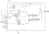
Fig. 1 ] represents schematically the main vehicle's components and data involved in the implementation of the method according to an embodiment of the invention. - [
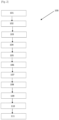
Fig. 2 ] represents the sequence diagram of the steps of the method according to an embodiment of the invention. - The
method 100 according to the invention is intended to estimate a driver's driving style safety level, and to provide accordingly driving recommendations DR to the driver DRI to improve the driver's driving style safety level. - The vehicle comprises an electronic control unit ECU, sensors S and a communication bus CB configured to convey data measured by the sensors S to the electronic control unit ECU, the electronic control unit being configured to run (1) a machine learning processing module, such as a neural network module NNM, (2) a physics-based processing module PPM, (3) a feedback module FM, and (4) a vehicle simulation module VSM.
- The sensors S are provided to collect, at
step 101 of themethod 100, measured sensor data MSD, measured during a certain period of time; the measured sensor data MSD comprise (1) driver signals DS concerning driver actions, (2) vehicle state signals VSS, and (3) road environment data ED. The sensors are further configured to communicate these measured sensor data MSD to the electronic control unit ECU via a communication bus, for example via a standard CAN bus. - Driver signals DS, which are the result of the driver's action on the vehicle, comprise signals such as a brake pedal position signal BPS, a throttle pedal position signal THS, a steering angle signal SAS, switches in the dash, etc....
- Vehicle state signals VSS, may include a wheel speed signal WSS, a vehicle accelerometer signal VAS, a yaw rate signal, and a roll rate signal, etc....
- Road environment data ED, comprise signals related to the road environment such as a vehicle position signal VPS, a road inclination INC, a road surface RS index etc...
- The vehicle position signal may for example be a GPS position.
- The more sensors are involved, the more accurate the
method 100 will be. - Measured sensor data MSD collected at
step 101, is then provided, at anext step 102, to the physics-based processing module PPM, and, atstep 103, to the neural network module NNM. - The physics-based processing module PPM is configured to process, at
step 102, the measured sensor data MSD based on a physics based model, and to produce two types of output : a physics-based route classification PRC, i.e. a route classification based on the physics based model used to process the measured sensor data MSD, and a physics-based driver's driving style classification PDSC, i.e. a driver's driving style classification based on the physics based model used to process the measured sensor data MSD. - The physics-based processing of the signals provided with the measured sensor data MSD may typically comprise using Fast Fourier Transform (FFT), preferably according to PWelch method, of the measured sensor data MSD, measured during said period of time. Using Fast Fourier Transform for the processing of input signals will provide output signals in the frequency domain, typically a power with respect to a frequency, the power being indicative of the amplitude of variations of the input signal at said frequency.
- The neural network module NNM, on the other hand, is configured, by training, to predict a neural network output NNO comprising a machine learning route classification MLRC and a machine learning driver's driving style classification MLDSC.
- For example, considering a driver DRI driving rash in two lane curvy hilly roads. He drastically accelerates to overtake a vehicle in the front and drastically brakes to get back to the speed limit because there is another car in front of him. Further, the driver also sways around traffic by constantly changing lanes. This would typically correspond to a dangerous the driving style.
- According to the invention, among all the CAN BUS signals, example measured sensor data MSD signals are provided such as: among driver signals DS, such as throttle, brake, steering, among vehicle state signals VSS, such as vehicle speed, and among environment data signals ED, such as a road inclination, a road surface index.
- When these signals pass through the FFT signal processing, the power provided by the FFT output from throttle, brake and vehicle speed exceeds a limit - stating that the driver is accelerating and braking very frequently in a rash manner. Similarly, in steering input, the FFT output power would be more than a limit value proving that the driver is constantly changing lanes. This limit value will be decided on multiple parameters, example - limit value will be decreased for hilly regions since it's more dangerous there to drive rash. Depending on the road surface like pot holes or GPS data, if it's a mountain or a highway, the limit value will change. Anything above the limit will say that the driver has high frequent unsafe maneuvers.
- Thus, taking into account the power spectrum of the signals output by the physics-based processing module PPM, said physics-based processing module is further configured to provide a physics-based route classification PRC, and a physics-based driver's driving style classification PDSC.
- The physics-based driver's driving style classification may for example determine that the driver's driving style belongs to one of the following categories:
- Unsafe lane changes
- Frequent Lane changes
- Safe steering
- Harsh late braking
- Safe braking
- Rapid throttle control
- Smooth throttle control
- Good vehicle speed limit maintenance
- Poor speed limit maintenance
- Etc.
- And the physics-based route classification may for example determine that the route belongs to one of the following categories:
- Hilly roads
- 5 lanes highways
- Interstate highways
- City roads
- Flat terrains
- Unpaved road
- Poor road surface
- Etc.
- The same measured sensor data MSD signals inputs go, at
step 103, into the neural network module NNM, which has been trained, taking enormous data from rash driving to smooth driving, to classify these inputs into the same few categories as shown above for the machine learning driver's driving style classification MLDSC, i.e. : - Unsafe lane changes
- Frequent Lane changes
- Safe steering
- Harsh late braking
- Safe braking
- Rapid throttle control
- Smooth throttle control
- Good vehicle speed limit maintenance
- Poor speed limit maintenance
- Etc.
- Likewise, the neural network module NNM, has been trained, taking enormous data from different types of route, to classify these inputs into the same few categories as shown above for the machine learning route classification MLRC, i.e.:
- Hilly roads
- 5 lanes highways
- Interstate highways
- City roads
- Flat terrains
- Unpaved road
- Poor road surface
- Etc.
- The training of the neural network module NNM uses recording data and truth labelling this data.
- The neural network module is preferably a recurrent neural network, configured to be provided time series of data as input.
- Thus, the output of the neural network module NNM, at
step 103 of the method according to the invention, is the neural network output NNO comprising the machine learning route classification MLRC and the machine learning driver's driving style classification MLDSC; the output of the signal physics-based processing module PPM, atstep 102 of the method, is the processed sensor data PSD comprising a physics-based route classification PRC and a physics-based driver's driving style classification PDSC. - Step 102 and step 103 of the method are advantageously performed in parallel and simultaneously.
- At
next step 104 of the method, the physics-based route classification PRC and the physics-based driver's driving style classification PDSC, and the machine learning route classification MLRC and the machine learning driver's driving style classification MLDSC, as input to the feedback module FM. - The feedback module is configured to estimate a driving recommendation DR for the driver based on a combination of the physics-based route classification PRC and the physics-based driver's driving style classification PDSC, and the machine learning route classification MLRC and the machine learning driver's driving style classification MLDSC, provided to the feedback module FM. The driving recommendation DR may be for example : the driver should brake sooner and change lanes less frequently.
- For example, the feedback module uses a look up table and confirm for this route classified and for this driving style the safe maneuver is to brake sooner, turn smoothly and change lanes less frequently.
- An example of such a look-u table is provided here :

- As indicated above, inputs for the feedback module FM are the route and driving style predicted by both data driven approach, i.e. by the neural network module NNM and by physics-based approach, i.e. by the physics-based processing module PPM. Now, the simple look up table, based on these inputs, provides a predetermined feedback to improve the driving safety.
- In the specific example illustrated here in the look up table by the highlighted lines of the lookup tables, it will provide a feedback to the driver to not change lanes or overtake often in hilly regions. Which means, trying to maintain the point A to point B route in GPS for one or more periods of time but with minimal steering variations.
- At the
next steps - The vehicle simulation module VSM is configured to receive as input emulated driver signals EDS and the environment data ED; the emulation of the driver signals is performed first, at
step 105 of the method, by an emulation module EM, based on the driving recommendation DR. The actions recommended by the driving recommendation DR will need driver signals DS to be emulated like the steering, throttle and brakes. The emulated driver signals EDS, as recommended by the driving recommendation DR from the feedback module FM, is generated as input for the vehicle simulation module VSM. The emulated driver signals EDS will typically comprise signals such as steering, throttle, brakes, etc... emulated according to the driving recommendation. - The vehicle simulation module VSM is configured to simulate at
step 106 of the method, the vehicle so as to output simulated state vehicle signals SVSS, like yaw rate, lateral acceleration etc... , similar to the vehicle state CAN signals that are observed from the vehicle in the real world; simulated state vehicle signals SVSS are generated by the vehicle simulation module VSM based on the emulated driver signals EDS, like steering, throttle, brakes, and switches, and on the environmental data ED signals like road inclination etc. In other words, the vehicle simulation module VSM will use the environment conditions - road surface, inclination, vehicle position, etc. and simulate the vehicle state signals SVSS based on the emulated driver signals EDS like steering, brake and throttle according to the recommended actions of the driving recommendation DR. - At
next step 107 of the method, the emulated driver signals EDS and the simulated vehicle state signals SVSS, and the environment data ED signal is input to the physics-based processing module PPM and to the neural network module NNM. - At
next step 108, the emulated driver signals EDS and the simulated vehicle state signals SVSS and the environment data ED signal is processed by the physics-based processing module PPM, in a similar way as the measured sensor data MSD was previously processed atstep 102 of the method by the physics-based processing module PPM, to produce similarly processed simulated sensor data PSSD, the processed simulated sensor data PSSD comprising a simulated physics-based route classification SPRC and a simulated physics-based driver's driving style classification SPDSC. - At
next step 109, the emulated driver signals EDS and the simulated vehicle state signals SVSS and the environment data ED signal is processed by the neural network module NNM, in a similar way as the measured sensor data MSD was previously processed atstep 102 of the method by the neural network module NNM, to produce similarly simulated neural network output SNNO, the simulated neural network output SNNO comprising a simulated machine learning route classification SMLRC and a simulated machine learning driver's driving style classification SMLDSC. - At
next step 110, the feedback module FM is provided the simulated physics-based route classification SPRC and the simulated physics-based driver's driving style classification SPDSC and the simulated machine learning route classification SMLRC and the simulated machine learning driver's driving style classification SMLDSC, the feedback module FM being further configured to check whether the driving recommendation DR has improved the safety level. - Depending on the result of the checking by the feedback module FM, provide the driving recommendation DR is provided, at
step 111 of the method, to the driver DRI to improve the driver's driving style safety level. - According to these provisions, the driving recommendation DR estimated at
step 104 of the method is provided to the driver DRI only if the step of checking has demonstrated that the driver's driving style safety level is improved by the applying said driving recommendation DR. - The
method 100 will be further described, herein below, according to another example, considering a highly manoeuvring driver with constant speed changes in urban areas. - In this specific example, the driver signals DS recorded show up that the driver has constantly changed lanes and show drastic speed changes; the vehicle state signals VSS show flat roads from the GPS and varying speed limits of the vehicle showing that it is on urban roads.
- In this specific example, the neural network module NNM provides an output of urban region and driver frequently manoeuvring. Similarly, the FFT computed by the physics-based processing module PPM, shows higher values in the frequency of the steering signal than usual and the same is observed in the vehicle speed signal.
- This is reflected in the highlighted lines of the lookup table below :

- In this specific example, the feedback module FM estimates a driving recommendation DR to maintain speed decently or reduce steering corrections. Which means, trying to maintain the point A to point B route in GPS for one or more periods of time but with minimal steering variations and speed variants. This driving recommendation DR is sent to the vehicle simulation module for verification to check if the estimated driving recommendation is good or not.
- In this specific example, the urban region signals, and other environmental signals are recreated. The emulated driver signals EDS recommended by the feedback module is generated as input for the vehicle in the vehicle simulation module VSM. In this case, the steering to be less corrected and throttle/brake to be less frequent.
- The simulation is run based on the environmental data ED signals like road inclination, road surface etc. and based on the emulated driver signals EDS like steering, throttle, brakes, and switches in the dash. The vehicle simulation module VSM generates simulated vehicle state signals SVSS similar in nature to vehicle state signals VSS observed from the vehicle in the real world. The simulated vehicle state signals SVSS show that the vehicle cannot reach point B from point A and all necessary simulated CAN signals, i.e. simulated vehicle state signals SVSS and emulated driver signals EDS, like yaw rate, lateral acceleration etc. are recorded and sent to the physics-based processing module PPM and to the neural network module NNM. Also, the yaw rate values being higher due to trying to maintain smoother vehicle speed could have been dangerous in turning in sharp curves in urban areas.
- These simulated CAN signals, i.e. simulated vehicle state signals SVSS and emulated driver signals EDS, sent to the physics-based processing module PPM and to the neural network module NNM the output of which is sent to the feedback module FM configured to evaluate the driving that is performed in the simulation world based on the recommended driver signals. In this specific example, the recreated environment signals are indicative of a urban road with reduced driver speed control input frequency. This is predicted for the simulated signals and sent to the feedback module FM.
- The feedback module FM based on the classification input provided by the neural network module NNM and by the physics-based processing module PPM based on the simulated vehicle state signals SVSS and on emulated drivers signals EDS, determines a less safe driving style compared to the previous classification input provided by the neural network module NNM and by the physics-based processing module PPM based on the real-world vehicle state signals VSS and on real world drivers signals DS. Since the feedback modules does not determine a better safety level than the actual real world signals, this driver recommendation is not provided to the driver DRI.
- According to an aspect, the invention relates to a computer program comprising a set of instructions executable on a computer or a processing unit, the set of instructions being configured to implement the
method 100 according to anyone of the embodiments described herein above, when the instructions are executed by the computer or the processing unit. - According to a further aspect, the invention relates to an electronic control unit ECU configured to communicate with a communication bus of a vehicle so as to collect data time series measured during a period of time by sensors S installed on the vehicle, the electronic control unit ECU being configured to run a vehicle simulation module VSM, a neural network module NNM, preferably a recurrent neural network RNN, a feedback module FM, and a physics-based processing module PPM, the electronic control unit ECU further comprising processing unit and a memory unit, the memory unit comprising a computer program as described herein above.
- According to a further aspect, the invention relates to a vehicle comprising an electronic control unit ECU according as described herein above.
Claims (11)
- Method (100) for estimating and for improving, based on a safety level criteria, a driver's (DRI) driving style in a vehicle, the vehicle comprising an electronic control unit (ECU), sensors (S) and a communication bus (CB) configured to convey data measured by the sensors (S) to the electronic control unit (ECU), the electronic control unit being configured to run a vehicle simulation module (VSM), a neural network module (NNM), a feedback module (FM), and a physics-based processing module (PPM), the method (100) comprising the following steps implemented by the electronic control unit (ECU):- collect (101) measured sensor data (MSD) measured by the sensors (S) during a period of time, the measured sensor data (MSD) comprising environment data (ED), driver signals (DS) and vehicle state signals (VSS);- process (102) by the physics-based processing module (PPM) the measured sensor data (MSD), in frequency domain, to produce, based on a physics based model, processed sensor data (PSD), the processed sensor data (PSD) comprising a physics-based route classification (PRC) and a physics-based driver's driving style classification (PDSC);- feed (103) measured sensor data (MSD) as input to the neural network module (NNM) trained for predicting a neural network output (NNO), the neural network output (NNO) comprising a machine learning route classification (MLRC) and a machine learning driver's driving style classification (MLDSC);- provide (104) the physics-based route classification (PRC) and the physics-based driver's driving style classification (PDSC), and the machine learning route classification (MLRC) and the machine learning driver's driving style classification (MLDSC), as input to the feedback module (FM) configured to estimate a driving recommendation (DR) for the driver,- input (105) the driving recommendation (DR) to an emulation module (EM), the emulation module (EM) being configured to provide emulated driver signals (EDS) based on the driving recommendation (DR),- input (106) the emulated driver signals (EDS) and the environment data (ED) to the vehicle simulation module (VSM), the vehicle simulation module (VSM) being configured to simulate the vehicle, based on the emulated driver signals (EDS) and on the environment data (ED), to provide simulated vehicle state signals (SVSS),- process (108), by the physics-based processing module (PPM), the emulated driver signals (EDS) and the simulated vehicle state signals (SVSS) and the environment data (ED), in frequency domain, to produce processed simulated sensor data (PSSD), the processed simulated sensor data (PSSD) comprising a simulated physics-based route classification (SPRC) and a simulated physics-based driver's driving style classification (SPDSC);- process (109), by the neural network module (NNM), the emulated driver signals (EDS) and the simulated vehicle state signals (SVSS) and the environment data (ED) to predict a simulated neural network output (SNNO), the simulated neural network output (SNNO) comprising a simulated machine learning route classification (SMLRC) and a simulated machine learning driver's driving style classification (SMLDSC);- provide (110) to the feedback module (FM) the simulated physics-based route classification (SPRC) and the simulated physics-based driver's driving style classification (SPDSC) and the simulated machine learning route classification (SMLRC) and the simulated machine learning driver's driving style classification (SMLDSC), the feedback module (FM) being further configured to check whether the driving recommendation (DR) has improved the safety level,- depending on the result of the checking by the feedback module (FM), provide (111) the driving recommendation to the driver (DRI) to improve the driver's driving style safety level.
- Method according to claim 1, wherein the driver signals (DS) comprise at least one signal resulting from an action of the driver.
- Method according to claim 2, wherein the driver signals (DS) comprise at least one of a brake pedal position signal (BPS), a throttle pedal position signal (THS), a steering angle signal (SAS).
- Method according to claim 1, wherein the vehicle state signals (VSS) comprise at least one of a wheel speed signal (WSS), a vehicle accelerometer signal (VAS), a yaw rate signal, and a roll rate signal.
- Method according to claim 1, wherein the environment data (ED) comprise at least one of a vehicle position signal (VPS), a road inclination signal (INC), a road surface (RS) index.
- Method according to anyone of previous claims, wherein the processing steps by the physics-based processing module (PPM) comprise using Fast Fourier Transformation, preferably according to PWelch method, of the measured sensor data (MSD) collected, or of the emulated driver signals (EDS) and the simulated vehicle state signals (SVSS) and the environment data (ED).
- Method according to anyone of previous claims, wherein the neural network module is a recurrent neural network.
- Method according to anyone of previous claims, wherein the driving style classification is one of rash, smooth, conservative, dangerous.
- Computer program comprising a set of instructions executable on a computer or a processing unit, the set of instructions being configured to implement the method (100) according to anyone of claims 1 to 8, when the instructions are executed by the computer or the processing unit.
- Electronic control unit (ECU) configured to communicate with a communication bus of a vehicle so as to collect data time series measured during a period of time by sensors (S) installed on the vehicle, the electronic control unit (ECU) being configured to run a vehicle simulation module (VSM), a neural network module (NNM), preferably a recurrent neural network (RNN), a feedback module (FM), and a physics-based processing module (PPM), the electronic control unit (ECU) further comprising processing unit and a memory unit, the memory unit comprising a computer program according to claim 9.
- Vehicle comprising an electronic control unit (ECU) according to claim 10.
Priority Applications (3)
| Application Number | Priority Date | Filing Date | Title |
|---|---|---|---|
| EP21203349.2A EP4169794B1 (en) | 2021-10-19 | 2021-10-19 | A method for rating and for improving a driver's driving style based on a safety level criteria, corresponding computer program and electronic control unit |
| CN202211265678.3A CN116022153A (en) | 2021-10-19 | 2022-10-17 | Method for assessing and improving driver's driving style based on safety level standards |
| US18/047,403 US20230242126A1 (en) | 2021-10-19 | 2022-10-18 | Method for rating and for improving a driver's driving style based on a safety level criteria |
Applications Claiming Priority (1)
| Application Number | Priority Date | Filing Date | Title |
|---|---|---|---|
| EP21203349.2A EP4169794B1 (en) | 2021-10-19 | 2021-10-19 | A method for rating and for improving a driver's driving style based on a safety level criteria, corresponding computer program and electronic control unit |
Publications (3)
| Publication Number | Publication Date |
|---|---|
| EP4169794A1 true EP4169794A1 (en) | 2023-04-26 |
| EP4169794C0 EP4169794C0 (en) | 2024-07-17 |
| EP4169794B1 EP4169794B1 (en) | 2024-07-17 |
Family
ID=78592406
Family Applications (1)
| Application Number | Title | Priority Date | Filing Date |
|---|---|---|---|
| EP21203349.2A Active EP4169794B1 (en) | 2021-10-19 | 2021-10-19 | A method for rating and for improving a driver's driving style based on a safety level criteria, corresponding computer program and electronic control unit |
Country Status (3)
| Country | Link |
|---|---|
| US (1) | US20230242126A1 (en) |
| EP (1) | EP4169794B1 (en) |
| CN (1) | CN116022153A (en) |
Families Citing this family (1)
| Publication number | Priority date | Publication date | Assignee | Title |
|---|---|---|---|---|
| CN120245985A (en) * | 2025-06-05 | 2025-07-04 | 重庆长安汽车股份有限公司 | Driving style determination method, device, electronic equipment and vehicle |
Citations (4)
| Publication number | Priority date | Publication date | Assignee | Title |
|---|---|---|---|---|
| US20070213886A1 (en) * | 2006-03-10 | 2007-09-13 | Yilu Zhang | Method and system for driver handling skill recognition through driver's steering behavior |
| US20100023223A1 (en) * | 2008-07-24 | 2010-01-28 | Gm Global Technology Operations, Inc. | Adaptive vehicle control system with driving style recognition |
| US20110193693A1 (en) * | 2008-10-30 | 2011-08-11 | Ford Global Technologies, Llc | Vehicle and method for advising driver of same |
| WO2019165838A1 (en) * | 2018-03-01 | 2019-09-06 | Beijing Didi Infinity Technology And Development Co., Ltd. | Systems and methods for identifying risky driving behavior |
-
2021
- 2021-10-19 EP EP21203349.2A patent/EP4169794B1/en active Active
-
2022
- 2022-10-17 CN CN202211265678.3A patent/CN116022153A/en active Pending
- 2022-10-18 US US18/047,403 patent/US20230242126A1/en not_active Abandoned
Patent Citations (4)
| Publication number | Priority date | Publication date | Assignee | Title |
|---|---|---|---|---|
| US20070213886A1 (en) * | 2006-03-10 | 2007-09-13 | Yilu Zhang | Method and system for driver handling skill recognition through driver's steering behavior |
| US20100023223A1 (en) * | 2008-07-24 | 2010-01-28 | Gm Global Technology Operations, Inc. | Adaptive vehicle control system with driving style recognition |
| US20110193693A1 (en) * | 2008-10-30 | 2011-08-11 | Ford Global Technologies, Llc | Vehicle and method for advising driver of same |
| WO2019165838A1 (en) * | 2018-03-01 | 2019-09-06 | Beijing Didi Infinity Technology And Development Co., Ltd. | Systems and methods for identifying risky driving behavior |
Also Published As
| Publication number | Publication date |
|---|---|
| EP4169794C0 (en) | 2024-07-17 |
| US20230242126A1 (en) | 2023-08-03 |
| EP4169794B1 (en) | 2024-07-17 |
| CN116022153A (en) | 2023-04-28 |
Similar Documents
| Publication | Publication Date | Title |
|---|---|---|
| US11107002B2 (en) | Reinforcement learning based ground vehicle control techniques | |
| US10843689B2 (en) | Collision avoidance for a connected vehicle based on a digital behavioral twin | |
| Alam et al. | Experimental evaluation of decentralized cooperative cruise control for heavy-duty vehicle platooning | |
| CN103347757B (en) | System and method for optimizing fuel economy by using predictive environmental and driver behavior information | |
| US20190378041A1 (en) | Predictive control techniques for ground vehicles | |
| CN101101702A (en) | Inter-vehicle information sharing automatic driving system and control method thereof | |
| CN109760678A (en) | A kind of method for limiting speed of automotive self-adaptive cruise system | |
| CN111332283A (en) | Method and system for controlling a motor vehicle | |
| CN113085852A (en) | Behavior early warning method and device for automatic driving vehicle and cloud equipment | |
| US20230115857A1 (en) | Computer-assisted driving method and apparatus including automatic mitigation of potential emergency | |
| EP3666612A1 (en) | Vehicle control device | |
| CN113548050A (en) | Vehicle running control method, device, system and storage medium | |
| JP2018509705A (en) | How to control the distance between vehicles | |
| CN113076897B (en) | Game dynamic driving safety measurement and control method and terminal for intelligent network-connected automobile | |
| CN114604252A (en) | Indirect verification of speed limits based on contextual information of autonomous and semi-autonomous driving systems | |
| CN115601954B (en) | Lane change judgment method, device, equipment and medium for intelligent networked fleet | |
| Lee et al. | Development of a driving behavior-based collision warning system using a neural network | |
| US20230242126A1 (en) | Method for rating and for improving a driver's driving style based on a safety level criteria | |
| CN114103966A (en) | Control method, device and system for driving assistance | |
| Zhao et al. | “InfoRich” eco-driving control strategy for connected and automated vehicles | |
| CN113635900A (en) | Energy management-based lane change decision control method in prediction cruise process | |
| Ying et al. | Research on adaptive cruise control systems and performance analysis using Matlab and Carsim | |
| CN113276858A (en) | Fuel-saving driving control method and device, computing equipment and storage medium | |
| CN112150668A (en) | Driving behavior reminding method and device | |
| Mihály et al. | Analysis of driver behavior related to look-ahead control |
Legal Events
| Date | Code | Title | Description |
|---|---|---|---|
| PUAI | Public reference made under article 153(3) epc to a published international application that has entered the european phase |
Free format text: ORIGINAL CODE: 0009012 |
|
| STAA | Information on the status of an ep patent application or granted ep patent |
Free format text: STATUS: THE APPLICATION HAS BEEN PUBLISHED |
|
| AK | Designated contracting states |
Kind code of ref document: A1 Designated state(s): AL AT BE BG CH CY CZ DE DK EE ES FI FR GB GR HR HU IE IS IT LI LT LU LV MC MK MT NL NO PL PT RO RS SE SI SK SM TR |
|
| STAA | Information on the status of an ep patent application or granted ep patent |
Free format text: STATUS: REQUEST FOR EXAMINATION WAS MADE |
|
| 17P | Request for examination filed |
Effective date: 20230427 |
|
| RBV | Designated contracting states (corrected) |
Designated state(s): AL AT BE BG CH CY CZ DE DK EE ES FI FR GB GR HR HU IE IS IT LI LT LU LV MC MK MT NL NO PL PT RO RS SE SI SK SM TR |
|
| GRAP | Despatch of communication of intention to grant a patent |
Free format text: ORIGINAL CODE: EPIDOSNIGR1 |
|
| STAA | Information on the status of an ep patent application or granted ep patent |
Free format text: STATUS: GRANT OF PATENT IS INTENDED |
|
| INTG | Intention to grant announced |
Effective date: 20240424 |
|
| GRAS | Grant fee paid |
Free format text: ORIGINAL CODE: EPIDOSNIGR3 |
|
| GRAA | (expected) grant |
Free format text: ORIGINAL CODE: 0009210 |
|
| STAA | Information on the status of an ep patent application or granted ep patent |
Free format text: STATUS: THE PATENT HAS BEEN GRANTED |
|
| AK | Designated contracting states |
Kind code of ref document: B1 Designated state(s): AL AT BE BG CH CY CZ DE DK EE ES FI FR GB GR HR HU IE IS IT LI LT LU LV MC MK MT NL NO PL PT RO RS SE SI SK SM TR |
|
| REG | Reference to a national code |
Ref country code: CH Ref legal event code: EP |
|
| REG | Reference to a national code |
Ref country code: DE Ref legal event code: R096 Ref document number: 602021015744 Country of ref document: DE |
|
| REG | Reference to a national code |
Ref country code: IE Ref legal event code: FG4D |
|
| U01 | Request for unitary effect filed |
Effective date: 20240724 |
|
| U07 | Unitary effect registered |
Designated state(s): AT BE BG DE DK EE FI FR IT LT LU LV MT NL PT SE SI Effective date: 20240806 |
|
| U20 | Renewal fee for the european patent with unitary effect paid |
Year of fee payment: 4 Effective date: 20240814 |
|
| PG25 | Lapsed in a contracting state [announced via postgrant information from national office to epo] |
Ref country code: NO Free format text: LAPSE BECAUSE OF FAILURE TO SUBMIT A TRANSLATION OF THE DESCRIPTION OR TO PAY THE FEE WITHIN THE PRESCRIBED TIME-LIMIT Effective date: 20241017 |
|
| PG25 | Lapsed in a contracting state [announced via postgrant information from national office to epo] |
Ref country code: GR Free format text: LAPSE BECAUSE OF FAILURE TO SUBMIT A TRANSLATION OF THE DESCRIPTION OR TO PAY THE FEE WITHIN THE PRESCRIBED TIME-LIMIT Effective date: 20241018 Ref country code: PL Free format text: LAPSE BECAUSE OF FAILURE TO SUBMIT A TRANSLATION OF THE DESCRIPTION OR TO PAY THE FEE WITHIN THE PRESCRIBED TIME-LIMIT Effective date: 20240717 |
|
| PG25 | Lapsed in a contracting state [announced via postgrant information from national office to epo] |
Ref country code: IS Free format text: LAPSE BECAUSE OF FAILURE TO SUBMIT A TRANSLATION OF THE DESCRIPTION OR TO PAY THE FEE WITHIN THE PRESCRIBED TIME-LIMIT Effective date: 20241117 |
|
| PG25 | Lapsed in a contracting state [announced via postgrant information from national office to epo] |
Ref country code: HR Free format text: LAPSE BECAUSE OF FAILURE TO SUBMIT A TRANSLATION OF THE DESCRIPTION OR TO PAY THE FEE WITHIN THE PRESCRIBED TIME-LIMIT Effective date: 20240717 |
|
| PG25 | Lapsed in a contracting state [announced via postgrant information from national office to epo] |
Ref country code: ES Free format text: LAPSE BECAUSE OF FAILURE TO SUBMIT A TRANSLATION OF THE DESCRIPTION OR TO PAY THE FEE WITHIN THE PRESCRIBED TIME-LIMIT Effective date: 20240717 Ref country code: RS Free format text: LAPSE BECAUSE OF FAILURE TO SUBMIT A TRANSLATION OF THE DESCRIPTION OR TO PAY THE FEE WITHIN THE PRESCRIBED TIME-LIMIT Effective date: 20241017 |
|
| PG25 | Lapsed in a contracting state [announced via postgrant information from national office to epo] |
Ref country code: RS Free format text: LAPSE BECAUSE OF FAILURE TO SUBMIT A TRANSLATION OF THE DESCRIPTION OR TO PAY THE FEE WITHIN THE PRESCRIBED TIME-LIMIT Effective date: 20241017 Ref country code: PL Free format text: LAPSE BECAUSE OF FAILURE TO SUBMIT A TRANSLATION OF THE DESCRIPTION OR TO PAY THE FEE WITHIN THE PRESCRIBED TIME-LIMIT Effective date: 20240717 Ref country code: NO Free format text: LAPSE BECAUSE OF FAILURE TO SUBMIT A TRANSLATION OF THE DESCRIPTION OR TO PAY THE FEE WITHIN THE PRESCRIBED TIME-LIMIT Effective date: 20241017 Ref country code: IS Free format text: LAPSE BECAUSE OF FAILURE TO SUBMIT A TRANSLATION OF THE DESCRIPTION OR TO PAY THE FEE WITHIN THE PRESCRIBED TIME-LIMIT Effective date: 20241117 Ref country code: HR Free format text: LAPSE BECAUSE OF FAILURE TO SUBMIT A TRANSLATION OF THE DESCRIPTION OR TO PAY THE FEE WITHIN THE PRESCRIBED TIME-LIMIT Effective date: 20240717 Ref country code: GR Free format text: LAPSE BECAUSE OF FAILURE TO SUBMIT A TRANSLATION OF THE DESCRIPTION OR TO PAY THE FEE WITHIN THE PRESCRIBED TIME-LIMIT Effective date: 20241018 Ref country code: ES Free format text: LAPSE BECAUSE OF FAILURE TO SUBMIT A TRANSLATION OF THE DESCRIPTION OR TO PAY THE FEE WITHIN THE PRESCRIBED TIME-LIMIT Effective date: 20240717 |
|
| PG25 | Lapsed in a contracting state [announced via postgrant information from national office to epo] |
Ref country code: SM Free format text: LAPSE BECAUSE OF FAILURE TO SUBMIT A TRANSLATION OF THE DESCRIPTION OR TO PAY THE FEE WITHIN THE PRESCRIBED TIME-LIMIT Effective date: 20240717 |
|
| PG25 | Lapsed in a contracting state [announced via postgrant information from national office to epo] |
Ref country code: CZ Free format text: LAPSE BECAUSE OF FAILURE TO SUBMIT A TRANSLATION OF THE DESCRIPTION OR TO PAY THE FEE WITHIN THE PRESCRIBED TIME-LIMIT Effective date: 20240717 |
|
| PG25 | Lapsed in a contracting state [announced via postgrant information from national office to epo] |
Ref country code: SK Free format text: LAPSE BECAUSE OF FAILURE TO SUBMIT A TRANSLATION OF THE DESCRIPTION OR TO PAY THE FEE WITHIN THE PRESCRIBED TIME-LIMIT Effective date: 20240717 |
|
| PLBE | No opposition filed within time limit |
Free format text: ORIGINAL CODE: 0009261 |
|
| STAA | Information on the status of an ep patent application or granted ep patent |
Free format text: STATUS: NO OPPOSITION FILED WITHIN TIME LIMIT |
|
| REG | Reference to a national code |
Ref country code: CH Ref legal event code: PL |
|
| 26N | No opposition filed |
Effective date: 20250422 |
|
| PG25 | Lapsed in a contracting state [announced via postgrant information from national office to epo] |
Ref country code: MC Free format text: LAPSE BECAUSE OF FAILURE TO SUBMIT A TRANSLATION OF THE DESCRIPTION OR TO PAY THE FEE WITHIN THE PRESCRIBED TIME-LIMIT Effective date: 20240717 |
|
| PG25 | Lapsed in a contracting state [announced via postgrant information from national office to epo] |
Ref country code: CH Free format text: LAPSE BECAUSE OF NON-PAYMENT OF DUE FEES Effective date: 20241031 |
|
| PG25 | Lapsed in a contracting state [announced via postgrant information from national office to epo] |
Ref country code: IE Free format text: LAPSE BECAUSE OF NON-PAYMENT OF DUE FEES Effective date: 20241019 |
|
| PG25 | Lapsed in a contracting state [announced via postgrant information from national office to epo] |
Ref country code: RO Free format text: LAPSE BECAUSE OF FAILURE TO SUBMIT A TRANSLATION OF THE DESCRIPTION OR TO PAY THE FEE WITHIN THE PRESCRIBED TIME-LIMIT Effective date: 20240717 |
|
| PG25 | Lapsed in a contracting state [announced via postgrant information from national office to epo] |
Ref country code: CY Free format text: LAPSE BECAUSE OF FAILURE TO SUBMIT A TRANSLATION OF THE DESCRIPTION OR TO PAY THE FEE WITHIN THE PRESCRIBED TIME-LIMIT; INVALID AB INITIO Effective date: 20211019 |
|
| PG25 | Lapsed in a contracting state [announced via postgrant information from national office to epo] |
Ref country code: HU Free format text: LAPSE BECAUSE OF FAILURE TO SUBMIT A TRANSLATION OF THE DESCRIPTION OR TO PAY THE FEE WITHIN THE PRESCRIBED TIME-LIMIT; INVALID AB INITIO Effective date: 20211019 |