EP4169692B1 - Apparatus for the manufacture and unloading of preforms for the manufacture of plastic containers - Google Patents
Apparatus for the manufacture and unloading of preforms for the manufacture of plastic containers Download PDFInfo
- Publication number
- EP4169692B1 EP4169692B1 EP22196905.8A EP22196905A EP4169692B1 EP 4169692 B1 EP4169692 B1 EP 4169692B1 EP 22196905 A EP22196905 A EP 22196905A EP 4169692 B1 EP4169692 B1 EP 4169692B1
- Authority
- EP
- European Patent Office
- Prior art keywords
- preforms
- unit
- control
- unloading
- inspection
- Prior art date
- Legal status (The legal status is an assumption and is not a legal conclusion. Google has not performed a legal analysis and makes no representation as to the accuracy of the status listed.)
- Active
Links
Images


Classifications
-
- B—PERFORMING OPERATIONS; TRANSPORTING
- B29—WORKING OF PLASTICS; WORKING OF SUBSTANCES IN A PLASTIC STATE IN GENERAL
- B29C—SHAPING OR JOINING OF PLASTICS; SHAPING OF MATERIAL IN A PLASTIC STATE, NOT OTHERWISE PROVIDED FOR; AFTER-TREATMENT OF THE SHAPED PRODUCTS, e.g. REPAIRING
- B29C45/00—Injection moulding, i.e. forcing the required volume of moulding material through a nozzle into a closed mould; Apparatus therefor
- B29C45/17—Component parts, details or accessories; Auxiliary operations
- B29C45/72—Heating or cooling
- B29C45/7207—Heating or cooling of the moulded articles
-
- B—PERFORMING OPERATIONS; TRANSPORTING
- B29—WORKING OF PLASTICS; WORKING OF SUBSTANCES IN A PLASTIC STATE IN GENERAL
- B29C—SHAPING OR JOINING OF PLASTICS; SHAPING OF MATERIAL IN A PLASTIC STATE, NOT OTHERWISE PROVIDED FOR; AFTER-TREATMENT OF THE SHAPED PRODUCTS, e.g. REPAIRING
- B29C49/00—Blow-moulding, i.e. blowing a preform or parison to a desired shape within a mould; Apparatus therefor
- B29C49/42—Component parts, details or accessories; Auxiliary operations
- B29C49/64—Heating or cooling preforms, parisons or blown articles
- B29C49/6409—Thermal conditioning of preforms
- B29C49/6427—Cooling of preforms
-
- B—PERFORMING OPERATIONS; TRANSPORTING
- B29—WORKING OF PLASTICS; WORKING OF SUBSTANCES IN A PLASTIC STATE IN GENERAL
- B29C—SHAPING OR JOINING OF PLASTICS; SHAPING OF MATERIAL IN A PLASTIC STATE, NOT OTHERWISE PROVIDED FOR; AFTER-TREATMENT OF THE SHAPED PRODUCTS, e.g. REPAIRING
- B29C45/00—Injection moulding, i.e. forcing the required volume of moulding material through a nozzle into a closed mould; Apparatus therefor
- B29C45/17—Component parts, details or accessories; Auxiliary operations
- B29C45/1769—Handling of moulded articles or runners, e.g. sorting, stacking, grinding of runners
-
- B—PERFORMING OPERATIONS; TRANSPORTING
- B29—WORKING OF PLASTICS; WORKING OF SUBSTANCES IN A PLASTIC STATE IN GENERAL
- B29C—SHAPING OR JOINING OF PLASTICS; SHAPING OF MATERIAL IN A PLASTIC STATE, NOT OTHERWISE PROVIDED FOR; AFTER-TREATMENT OF THE SHAPED PRODUCTS, e.g. REPAIRING
- B29C45/00—Injection moulding, i.e. forcing the required volume of moulding material through a nozzle into a closed mould; Apparatus therefor
- B29C45/17—Component parts, details or accessories; Auxiliary operations
- B29C45/40—Removing or ejecting moulded articles
- B29C45/42—Removing or ejecting moulded articles using means movable from outside the mould between mould parts, e.g. robots
-
- B—PERFORMING OPERATIONS; TRANSPORTING
- B29—WORKING OF PLASTICS; WORKING OF SUBSTANCES IN A PLASTIC STATE IN GENERAL
- B29C—SHAPING OR JOINING OF PLASTICS; SHAPING OF MATERIAL IN A PLASTIC STATE, NOT OTHERWISE PROVIDED FOR; AFTER-TREATMENT OF THE SHAPED PRODUCTS, e.g. REPAIRING
- B29C45/00—Injection moulding, i.e. forcing the required volume of moulding material through a nozzle into a closed mould; Apparatus therefor
- B29C45/17—Component parts, details or accessories; Auxiliary operations
- B29C45/76—Measuring, controlling or regulating
- B29C45/7686—Measuring, controlling or regulating the ejected articles, e.g. weight control
-
- B—PERFORMING OPERATIONS; TRANSPORTING
- B29—WORKING OF PLASTICS; WORKING OF SUBSTANCES IN A PLASTIC STATE IN GENERAL
- B29C—SHAPING OR JOINING OF PLASTICS; SHAPING OF MATERIAL IN A PLASTIC STATE, NOT OTHERWISE PROVIDED FOR; AFTER-TREATMENT OF THE SHAPED PRODUCTS, e.g. REPAIRING
- B29C49/00—Blow-moulding, i.e. blowing a preform or parison to a desired shape within a mould; Apparatus therefor
- B29C49/42—Component parts, details or accessories; Auxiliary operations
- B29C49/78—Measuring, controlling or regulating
-
- B—PERFORMING OPERATIONS; TRANSPORTING
- B29—WORKING OF PLASTICS; WORKING OF SUBSTANCES IN A PLASTIC STATE IN GENERAL
- B29C—SHAPING OR JOINING OF PLASTICS; SHAPING OF MATERIAL IN A PLASTIC STATE, NOT OTHERWISE PROVIDED FOR; AFTER-TREATMENT OF THE SHAPED PRODUCTS, e.g. REPAIRING
- B29C45/00—Injection moulding, i.e. forcing the required volume of moulding material through a nozzle into a closed mould; Apparatus therefor
- B29C45/17—Component parts, details or accessories; Auxiliary operations
- B29C45/72—Heating or cooling
- B29C45/7207—Heating or cooling of the moulded articles
- B29C2045/7214—Preform carriers for cooling preforms
-
- B—PERFORMING OPERATIONS; TRANSPORTING
- B29—WORKING OF PLASTICS; WORKING OF SUBSTANCES IN A PLASTIC STATE IN GENERAL
- B29C—SHAPING OR JOINING OF PLASTICS; SHAPING OF MATERIAL IN A PLASTIC STATE, NOT OTHERWISE PROVIDED FOR; AFTER-TREATMENT OF THE SHAPED PRODUCTS, e.g. REPAIRING
- B29C49/00—Blow-moulding, i.e. blowing a preform or parison to a desired shape within a mould; Apparatus therefor
- B29C49/42—Component parts, details or accessories; Auxiliary operations
- B29C49/78—Measuring, controlling or regulating
- B29C49/786—Temperature
- B29C2049/7861—Temperature of the preform
-
- B—PERFORMING OPERATIONS; TRANSPORTING
- B29—WORKING OF PLASTICS; WORKING OF SUBSTANCES IN A PLASTIC STATE IN GENERAL
- B29C—SHAPING OR JOINING OF PLASTICS; SHAPING OF MATERIAL IN A PLASTIC STATE, NOT OTHERWISE PROVIDED FOR; AFTER-TREATMENT OF THE SHAPED PRODUCTS, e.g. REPAIRING
- B29C49/00—Blow-moulding, i.e. blowing a preform or parison to a desired shape within a mould; Apparatus therefor
- B29C49/42—Component parts, details or accessories; Auxiliary operations
- B29C49/78—Measuring, controlling or regulating
- B29C2049/7874—Preform or article shape, weight, defect or presence
- B29C2049/78745—Weight or density
-
- B—PERFORMING OPERATIONS; TRANSPORTING
- B29—WORKING OF PLASTICS; WORKING OF SUBSTANCES IN A PLASTIC STATE IN GENERAL
- B29C—SHAPING OR JOINING OF PLASTICS; SHAPING OF MATERIAL IN A PLASTIC STATE, NOT OTHERWISE PROVIDED FOR; AFTER-TREATMENT OF THE SHAPED PRODUCTS, e.g. REPAIRING
- B29C49/00—Blow-moulding, i.e. blowing a preform or parison to a desired shape within a mould; Apparatus therefor
- B29C49/42—Component parts, details or accessories; Auxiliary operations
- B29C49/78—Measuring, controlling or regulating
- B29C2049/7874—Preform or article shape, weight, defect or presence
- B29C2049/7875—Size or shape
-
- B—PERFORMING OPERATIONS; TRANSPORTING
- B29—WORKING OF PLASTICS; WORKING OF SUBSTANCES IN A PLASTIC STATE IN GENERAL
- B29C—SHAPING OR JOINING OF PLASTICS; SHAPING OF MATERIAL IN A PLASTIC STATE, NOT OTHERWISE PROVIDED FOR; AFTER-TREATMENT OF THE SHAPED PRODUCTS, e.g. REPAIRING
- B29C49/00—Blow-moulding, i.e. blowing a preform or parison to a desired shape within a mould; Apparatus therefor
- B29C49/42—Component parts, details or accessories; Auxiliary operations
- B29C49/78—Measuring, controlling or regulating
- B29C2049/7874—Preform or article shape, weight, defect or presence
- B29C2049/78755—Optical properties
-
- B—PERFORMING OPERATIONS; TRANSPORTING
- B29—WORKING OF PLASTICS; WORKING OF SUBSTANCES IN A PLASTIC STATE IN GENERAL
- B29C—SHAPING OR JOINING OF PLASTICS; SHAPING OF MATERIAL IN A PLASTIC STATE, NOT OTHERWISE PROVIDED FOR; AFTER-TREATMENT OF THE SHAPED PRODUCTS, e.g. REPAIRING
- B29C49/00—Blow-moulding, i.e. blowing a preform or parison to a desired shape within a mould; Apparatus therefor
- B29C49/42—Component parts, details or accessories; Auxiliary operations
- B29C49/78—Measuring, controlling or regulating
- B29C2049/7874—Preform or article shape, weight, defect or presence
- B29C2049/7876—Defects
-
- B—PERFORMING OPERATIONS; TRANSPORTING
- B29—WORKING OF PLASTICS; WORKING OF SUBSTANCES IN A PLASTIC STATE IN GENERAL
- B29C—SHAPING OR JOINING OF PLASTICS; SHAPING OF MATERIAL IN A PLASTIC STATE, NOT OTHERWISE PROVIDED FOR; AFTER-TREATMENT OF THE SHAPED PRODUCTS, e.g. REPAIRING
- B29C2945/00—Indexing scheme relating to injection moulding, i.e. forcing the required volume of moulding material through a nozzle into a closed mould
- B29C2945/76—Measuring, controlling or regulating
- B29C2945/76003—Measured parameter
- B29C2945/7604—Temperature
-
- B—PERFORMING OPERATIONS; TRANSPORTING
- B29—WORKING OF PLASTICS; WORKING OF SUBSTANCES IN A PLASTIC STATE IN GENERAL
- B29C—SHAPING OR JOINING OF PLASTICS; SHAPING OF MATERIAL IN A PLASTIC STATE, NOT OTHERWISE PROVIDED FOR; AFTER-TREATMENT OF THE SHAPED PRODUCTS, e.g. REPAIRING
- B29C2945/00—Indexing scheme relating to injection moulding, i.e. forcing the required volume of moulding material through a nozzle into a closed mould
- B29C2945/76—Measuring, controlling or regulating
- B29C2945/76003—Measured parameter
- B29C2945/76153—Optical properties
-
- B—PERFORMING OPERATIONS; TRANSPORTING
- B29—WORKING OF PLASTICS; WORKING OF SUBSTANCES IN A PLASTIC STATE IN GENERAL
- B29C—SHAPING OR JOINING OF PLASTICS; SHAPING OF MATERIAL IN A PLASTIC STATE, NOT OTHERWISE PROVIDED FOR; AFTER-TREATMENT OF THE SHAPED PRODUCTS, e.g. REPAIRING
- B29C2945/00—Indexing scheme relating to injection moulding, i.e. forcing the required volume of moulding material through a nozzle into a closed mould
- B29C2945/76—Measuring, controlling or regulating
- B29C2945/76003—Measured parameter
- B29C2945/76163—Errors, malfunctioning
-
- B—PERFORMING OPERATIONS; TRANSPORTING
- B29—WORKING OF PLASTICS; WORKING OF SUBSTANCES IN A PLASTIC STATE IN GENERAL
- B29C—SHAPING OR JOINING OF PLASTICS; SHAPING OF MATERIAL IN A PLASTIC STATE, NOT OTHERWISE PROVIDED FOR; AFTER-TREATMENT OF THE SHAPED PRODUCTS, e.g. REPAIRING
- B29C2945/00—Indexing scheme relating to injection moulding, i.e. forcing the required volume of moulding material through a nozzle into a closed mould
- B29C2945/76—Measuring, controlling or regulating
- B29C2945/76451—Measurement means
- B29C2945/76461—Optical, e.g. laser
- B29C2945/76464—Optical, e.g. laser cameras
-
- B—PERFORMING OPERATIONS; TRANSPORTING
- B29—WORKING OF PLASTICS; WORKING OF SUBSTANCES IN A PLASTIC STATE IN GENERAL
- B29C—SHAPING OR JOINING OF PLASTICS; SHAPING OF MATERIAL IN A PLASTIC STATE, NOT OTHERWISE PROVIDED FOR; AFTER-TREATMENT OF THE SHAPED PRODUCTS, e.g. REPAIRING
- B29C2949/00—Indexing scheme relating to blow-moulding
- B29C2949/07—Preforms or parisons characterised by their configuration
- B29C2949/0715—Preforms or parisons characterised by their configuration the preform having one end closed
-
- B—PERFORMING OPERATIONS; TRANSPORTING
- B29—WORKING OF PLASTICS; WORKING OF SUBSTANCES IN A PLASTIC STATE IN GENERAL
- B29C—SHAPING OR JOINING OF PLASTICS; SHAPING OF MATERIAL IN A PLASTIC STATE, NOT OTHERWISE PROVIDED FOR; AFTER-TREATMENT OF THE SHAPED PRODUCTS, e.g. REPAIRING
- B29C49/00—Blow-moulding, i.e. blowing a preform or parison to a desired shape within a mould; Apparatus therefor
- B29C49/02—Combined blow-moulding and manufacture of the preform or the parison
- B29C49/06—Injection blow-moulding
-
- B—PERFORMING OPERATIONS; TRANSPORTING
- B29—WORKING OF PLASTICS; WORKING OF SUBSTANCES IN A PLASTIC STATE IN GENERAL
- B29C—SHAPING OR JOINING OF PLASTICS; SHAPING OF MATERIAL IN A PLASTIC STATE, NOT OTHERWISE PROVIDED FOR; AFTER-TREATMENT OF THE SHAPED PRODUCTS, e.g. REPAIRING
- B29C49/00—Blow-moulding, i.e. blowing a preform or parison to a desired shape within a mould; Apparatus therefor
- B29C49/42—Component parts, details or accessories; Auxiliary operations
- B29C49/4205—Handling means, e.g. transfer, loading or discharging means
- B29C49/42065—Means specially adapted for transporting preforms
-
- B—PERFORMING OPERATIONS; TRANSPORTING
- B29—WORKING OF PLASTICS; WORKING OF SUBSTANCES IN A PLASTIC STATE IN GENERAL
- B29C—SHAPING OR JOINING OF PLASTICS; SHAPING OF MATERIAL IN A PLASTIC STATE, NOT OTHERWISE PROVIDED FOR; AFTER-TREATMENT OF THE SHAPED PRODUCTS, e.g. REPAIRING
- B29C49/00—Blow-moulding, i.e. blowing a preform or parison to a desired shape within a mould; Apparatus therefor
- B29C49/42—Component parts, details or accessories; Auxiliary operations
- B29C49/4205—Handling means, e.g. transfer, loading or discharging means
- B29C49/42093—Transporting apparatus, e.g. slides, wheels or conveyors
- B29C49/42097—Sliding rails, e.g. inclined
- B29C49/42099—Pushing by air
-
- B—PERFORMING OPERATIONS; TRANSPORTING
- B29—WORKING OF PLASTICS; WORKING OF SUBSTANCES IN A PLASTIC STATE IN GENERAL
- B29C—SHAPING OR JOINING OF PLASTICS; SHAPING OF MATERIAL IN A PLASTIC STATE, NOT OTHERWISE PROVIDED FOR; AFTER-TREATMENT OF THE SHAPED PRODUCTS, e.g. REPAIRING
- B29C49/00—Blow-moulding, i.e. blowing a preform or parison to a desired shape within a mould; Apparatus therefor
- B29C49/42—Component parts, details or accessories; Auxiliary operations
- B29C49/4205—Handling means, e.g. transfer, loading or discharging means
- B29C49/42093—Transporting apparatus, e.g. slides, wheels or conveyors
- B29C49/42101—Conveyors, e.g. flat conveyor or clamping between two bands
-
- B—PERFORMING OPERATIONS; TRANSPORTING
- B29—WORKING OF PLASTICS; WORKING OF SUBSTANCES IN A PLASTIC STATE IN GENERAL
- B29C—SHAPING OR JOINING OF PLASTICS; SHAPING OF MATERIAL IN A PLASTIC STATE, NOT OTHERWISE PROVIDED FOR; AFTER-TREATMENT OF THE SHAPED PRODUCTS, e.g. REPAIRING
- B29C49/00—Blow-moulding, i.e. blowing a preform or parison to a desired shape within a mould; Apparatus therefor
- B29C49/42—Component parts, details or accessories; Auxiliary operations
- B29C49/4205—Handling means, e.g. transfer, loading or discharging means
- B29C49/42093—Transporting apparatus, e.g. slides, wheels or conveyors
- B29C49/42107—Transporting apparatus, e.g. slides, wheels or conveyors with accumulator or temporary storage, e.g. while waiting for the blowing apparatus
Definitions
- Apparatuses which are constituted by a device for the manufacture, by molding, of preforms made of plastic material and by devices for unloading and storing the manufactured preforms.
- the unloading devices are normally constituted by a cooling plate which forms a plurality of receptacles arranged in a matrix and designed to accommodate respective still-warm preforms for the time required to at least partially cool them.
- the mold opens and the cooling plate is moved towards the preforms partially accommodated in one of the two mold parts, so that the receptacles can engage respective portions of preforms that emerge from the mold part in order to extract them from it, so as to allow the closure of the mold and a new molding cycle.
- a device for cooling and extracting preforms for the manufacture of plastic containers is known from international application PCT/EP2021/052440 in the name of this same Applicant which comprises at least one grip assembly which forms a plurality of receptacles for respective preforms and means for transferring the still-warm preforms from an injection molding device to said grip assembly; the device comprises a cooling and extraction assembly which comprises a cooling plate which is arranged so as to face said grip assembly and can move on command between a position that is closer to the grip assembly and a position that is spaced from the grip assembly.
- the cooling plate supports a plurality of cooling channels which are designed, with the cooling plate in the closer position, to lead into a respective preform which is accommodated in a respective receptacle in order to convey a jet of air into the preform so as to increase its cooling rate.
- the cooling and extraction assembly comprises an unloading plate, which is arranged on the opposite side of the grip assembly with respect to the cooling plate and supports a plurality of grip bodies which can be moved on command in order to cross the cooling plate so as to engage selectively, with the cooling plate in the closer position, with a respective preform to allow its extraction from the respective receptacle.
- Devices for controlling the quality of molded preforms are also known from disclosures such as WO 2021/160474 A1 , WO 2005/037521 A1 , GB 2 528 934 A , WO 2018/036857 A1 and WO 2016/008928 A1 .
- a first method for performing preform quality control is the use of devices for quality control of the molded preforms constituted by a quality control unit which is arranged in line downstream of the press and is configured to control all the preforms that are manufactured, performing all the necessary controls and optionally rejecting nonconforming preforms.
- An orientation device is arranged between the press and the control unit, receives the non-oriented preforms from an unloading belt of the press and orients them in order to send them to the quality control unit.
- the order is random and therefore the unit must be provided with a video camera dedicated to reading the cavity number in order to identify from which mold cavity each controlled preform originates.
- a second method for performing preform quality control provides for the use of a unit that is arranged not in line with the press.
- an operator picks up, for example, at least one molding from the press and transfers it into the quality control unit, which performs the necessary controls, including weight control.
- the unit must be provided with a video camera dedicated to reading the cavity number, in order to identify from which cavity of the mold each preform originates.
- each device comprising the quality control device, is functionally connected to a computer, to an electrical panel, to a control system, etc., producing a redundancy of components which could be optimized.
- the hourly productivity of the apparatus must be aligned as regards the manufacturing device (press) and the quality control device, and in order to ensure the operation of the apparatus as a whole it is necessary to provide a bypass system that is capable of intervening in case of problems at the quality control device.
- control is performed offline, the intervention of an operator who goes to feed the control machine is necessary if one wishes to perform quality control of a molding.
- the aim of the present invention is to provide an apparatus for the manufacture and unloading of preforms for the manufacture of plastic containers that is capable of improving the background art in one or more of the aspects indicated above.
- an object of the invention is to provide an apparatus for the manufacture and unloading of preforms for the manufacture of plastic containers that allows to minimize the handling of the preforms to be controlled.
- Another object of the invention is to provide an apparatus for the manufacture and unloading of preforms for the manufacture of plastic containers that allows to reduce the number of units currently used, eliminating for example the need to use video cameras to detect the cavity number or the feeding and orientation devices, with consequent savings from the economic standpoint and in terms of space occupation, at the same time avoiding the generation of dust.
- the apparatus for the manufacture and unloading of preforms for the manufacture of plastic containers designated generally by the reference numeral 1, comprises a device 2 for molding (by injection) a plurality of preforms 10 and a device 3 for cooling and extracting the preforms 10 from the molding device.
- the cooling and extraction device 3 further comprises an unloading plate 20, which supports a plurality of grip bodies 21 which are arranged in a matrix and can be moved on command in order to engage selectively the grip assembly 4 to allow the extraction of the cooled preforms 10 from the respective receptacle and the unloading onto an unloading surface 22 of the preforms 10.
- the apparatus 1 comprises a device 30 for the selective extraction of a predetermined subset 31 of preforms 10 supported by the unloading plate 20 in an orderly manner along at least one pickup direction 201, and means for the orderly transfer of the predetermined subset 31 of preforms 10 to at least one control and inspection device 40 adapted to perform at least one control on the predetermined subset 31 of preforms 10.
- the unloading plate 20 supports a plurality of grip bodies 21 which are arranged in a matrix and are arranged along a plurality of rows 22a and a plurality of columns 22b which are substantially perpendicular to the plurality of rows 22a.
- the predetermined subset 31 of preforms 10 supported by the unloading plate 20 corresponds to the preforms 10 supported by at least one row 22a of the grip bodies 21, or to at least one column 22b of the grip bodies 21.
- the selective extraction device 30 comprises an elongated body 32 which forms means for supporting the preforms to be extracted.
- the selective extraction device 30 is configured to pick up selectively the preforms 10 supported by different rows 22a of the grip bodies and/or by different columns 22b of the grip bodies.
- control and inspection device 40 is associated functionally with means for the movement of the elongated body 32, which are adapted to move the elongated body 32 between a pickup position (shown in broken lines and in phantom lines in Figure 3 ), in which it is arranged proximate to the unloading plate 20 and faces respectively at least one respective row 22a and/or a respective column 22b, and a position for conveyance substantially at an unloading region which is arranged proximate to a conveyor 50 adapted to send the preforms 10 in an orderly manner at the control and inspection device 40.
- a pickup position shown in broken lines and in phantom lines in Figure 3
- a position for conveyance substantially at an unloading region which is arranged proximate to a conveyor 50 adapted to send the preforms 10 in an orderly manner at the control and inspection device 40.
- the means for the movement of the elongated body 32 comprise, for example, linear guides associated with respective actuators in order to allow their movement along a movement direction 202, at least from the pickup position to the conveyance position, and optionally also along a direction 203 which is substantially vertical, so as to be able to program the optimum movement trajectory.
- the movement direction can be extended substantially at right angles to the pickup direction 201.
- the elongated body 32 conveniently comprises a clamp structure to retain, at its mutually facing longitudinal edges 32a, the preforms 10.
- control and inspection device 40 comprises at least one unit chosen from the group comprising:
- the control and inspection device 40 further comprises at least one unit chosen in the group comprising:
- the apparatus 1 comprises, downstream of the conveyor 50, an accumulation system.
- the operation of the apparatus 1 according to the invention is as follows.
- the selective extraction device 30 and the control and inspection device 40 can be arranged within the space occupations of the molding, cooling and extraction device.
- the plastic is injected by means of an extruder into the molding device and is pressed.
- the grip assembly 4 extracts the preforms from the molding device 2 and, by virtue of known solutions, controls the cooling of the preforms 10.
- the unloading plate 20 picks up the preforms 10 from the grip assembly 4 with the task of moving them onto the unloading surface 22 constituted by the press extraction belt.
- the preforms 10 are released by the unloading plate 20 and are conveyed towards the outlet by means of the extraction belt and the extraction belt feeds them into octabins.
- the selective extraction device 30 comprises for example the elongated body 32, which can move along the movement direction 202, in order to convey the extracted preforms 10 to the control and inspection device 40.
- the elongated body 32 may furthermore be moved along the substantially vertical direction 203 in order to go to pick up and accommodate the preform 10 from the unloading plate 20 in a controlled manner and to release them, again in a controlled manner, to the conveyor 50.
- the elongated body 32 intervenes by picking up the preforms directly from the unloading plate 20, where they are arranged, as explained, in a matrix which duplicates the matrix of the mold.
- the invention by virtue of the possibility to move the elongated body 32 in the vicinity of the unloading plate 20, allows to pick up the preforms 10 without the risk of causing defects to them during the transfer step.
- the elongated body 32 picks up a column 22b and/or a row 22a and/or the entire matrix. Pickup occurs at each molding or at specific time intervals. If the system picks up a single column 22b or a single row 22a, it can perform this operation by deciding each time which of the i-th rows 22a or j-th columns 22b to pick up.
- the reference to the individual cavity of the mold is maintained up to the inside of the control and inspection device 40, allowing spot control on the individual specific cavity.
- the control and inspection device 40 loads the preforms 10 by means of the conveyor 50, which is configured to maintain their order and/or orientation.
- the conveyor 50 can for example comprise two oppositely rotating rollers, which maintain the order and orientation of the preforms 10 but not their spacing.
- roller conveyor allows to feed the preforms 10 to the control and inspection device 40 without causing defects to said preforms 10.
- the conveyor 50 is adapted to tilt by an angle which can also be fixed, allowing the preforms 10 to form a queue and continue in their flow.
- Timing system Downstream of the buffer there is a timing system which can be used or not as first inspection tracking.
- the timing system comprises, for example, a format star conveyor 51 which also acts as first tracking, but it might also be, by way of non-limiting example, a friction feeder or a pair of belts or chains.
- the top seal and the bottom of the preform 10 are inspected along the star conveyor 51.
- the preform 10 is handled under the sealing and tamper-evident ring or by means of another characteristic geometry by means of a transfer clamp 52 (which is pneumatic or electric).
- the transfer clamp 52 serves three stations, advantageously transferring two preforms at a time by means of an actuation system constituted by a pneumatic cylinder or by an electric actuator.
- the three stations can be for example constituted by a star conveyor extraction device, by a weighing module, which comprises the weight control unit 48, and a second rotation inspection tracking.
- the stations may be just two and the weighing module comprising the weight control unit 48 can be positioned downstream of the second tracking.
- the weighing module comprising the weight control unit 48 has a plate which supports the preform below the bottle neck (or laid down on the body or below the neck if it is arranged after the second tracking).
- Weighing occurs by isolating the weighing module that comprises the weight control unit 48 in a mechanical or electronic manner from the vibrations of the press.
- the preform 10 passes to the second tracking, where it is picked up by vacuum (or by means of a clamp).
- a movement axis allows to make the preform 10 translate upward, allowing one or more pyrometers 47 to detect one or more temperature profiles on the external body of the preform 10.
- One pyrometer 47 might be also positioned within the preform 10 in order to detect an internal profile.
- Detection of the cavity number allows to compare the actual order of arrival of the preforms in the control and inspection device 40 with the arrangement of the matrix of the mold, identifying any preforms lost in transport and thus reporting a possible problem to the automation system.
- a circumferential temperature profile can be detected by virtue of the pyrometer 47.
- the operator wishes to perform further controls on the preforms (for example destructive controls), by means of said separation means, constituted for example by the trapdoor, he can decide to pick up the preform for sampling.
- said separation means constituted for example by the trapdoor
- control and inspection device 40 detects a certain number of defective preforms that have functional or aesthetic defects, in some conditions it is possible to hypothesize, on the basis of these data, a relatively low overall quality of the preforms contained in a predetermined octabin and consequently report said octabin to assess any subsequent interventions.
- the control and inspection device 40 can be configured to control a series of parameters adapted to verify for example a "trend" of the apparatus 1, or of some parts thereof, which can generate a signal to the operator without thereby entailing the rejection of the controlled preforms 10.
- the inspection and control device 40 might report and recommend a check of said cavity during the subsequent intervention with machine downtime, also with the prospect, therefore, of preventive/predictive maintenance.
- the control and inspection device 40 can also be used as a system for the quick sampling of the preforms by means of a dedicated cycle that can be selected in an interface which speeds up extraction and excludes inspection, allowing immediate control by the operator and without contaminations.
- samplings can be also used to check the calibration of the device by means of bench tests. Sampling again occurs by means of the rejection trapdoor, which directs the flow into a box that can be extracted from a window.
- the application is particularly useful for process control, since it does not introduce defectiveness on the product. This means that the defects and measurements performed by the control system relate exclusively to the process of the press.
- the inspection system can also be installed as a retrofit kit, i.e., as an additional device that can be installed on already operational systems.
- the area in which the control and inspection device is located can have isolated access with respect to the molding device.
- the separation between the two areas can occur by means of safety distances which render access safe, by means of a separation with photoelectric barriers or by means of a separation with an actuated partition or other systems that are known in the art.
- the unloading plate 20 by means of adjustment devices, can directly pick up a predetermined subset 31 of preforms 10 (for example one or more rows 22a and/or one or more columns 22b) in order to send them to the control and inspection device 40.
- a predetermined subset 31 of preforms 10 for example one or more rows 22a and/or one or more columns 22b
Landscapes
- Engineering & Computer Science (AREA)
- Manufacturing & Machinery (AREA)
- Mechanical Engineering (AREA)
- Physics & Mathematics (AREA)
- Thermal Sciences (AREA)
- Robotics (AREA)
- Blow-Moulding Or Thermoforming Of Plastics Or The Like (AREA)
- Processing And Handling Of Plastics And Other Materials For Molding In General (AREA)
Description
- The present invention relates to an apparatus for the manufacture and unloading of preforms for the manufacture of plastic containers.
- Apparatuses are known which are constituted by a device for the manufacture, by molding, of preforms made of plastic material and by devices for unloading and storing the manufactured preforms.
- The unloading devices are normally constituted by a cooling plate which forms a plurality of receptacles arranged in a matrix and designed to accommodate respective still-warm preforms for the time required to at least partially cool them.
- Typically, these preforms are fed directly from the press, typically of the injection type, to the cooling plate and remain in the respective receptacle for a predetermined time.
- Specifically, once the injection molding process has ended, the mold opens and the cooling plate is moved towards the preforms partially accommodated in one of the two mold parts, so that the receptacles can engage respective portions of preforms that emerge from the mold part in order to extract them from it, so as to allow the closure of the mold and a new molding cycle.
- A device for cooling and extracting preforms for the manufacture of plastic containers is known from international application
PCT/EP2021/052440 - Devices for controlling the quality of molded preforms are also known from disclosures such as
WO 2021/160474 A1 ,WO 2005/037521 A1 ,GB 2 528 934 AWO 2018/036857 A1 andWO 2016/008928 A1 . - A first method for performing preform quality control is the use of devices for quality control of the molded preforms constituted by a quality control unit which is arranged in line downstream of the press and is configured to control all the preforms that are manufactured, performing all the necessary controls and optionally rejecting nonconforming preforms.
- If nonconforming preforms are detected, this is reported on the display of the unit and they are optionally rejected. An orientation device is arranged between the press and the control unit, receives the non-oriented preforms from an unloading belt of the press and orients them in order to send them to the quality control unit. The order is random and therefore the unit must be provided with a video camera dedicated to reading the cavity number in order to identify from which mold cavity each controlled preform originates.
- A second method for performing preform quality control provides for the use of a unit that is arranged not in line with the press. In this case, an operator picks up, for example, at least one molding from the press and transfers it into the quality control unit, which performs the necessary controls, including weight control. In this case also, the unit must be provided with a video camera dedicated to reading the cavity number, in order to identify from which cavity of the mold each preform originates.
- A final method that is used provides for performing a so-called partial statistical control. In particular, solutions have been developed which provide for the installation of video cameras in order to be able to perform some controls directly at the cooling plate (for example to control the color of the preforms) or on the preform evacuation belt. With this control method, however, it is possible to identify only some defects and only on some preforms which are not overlapping or oriented so as to allow the video cameras to acquire an effective image.
- Although the solutions described above are widely used, they have some drawbacks.
- In the first two cases it is necessary to provide an orientation device, i.e., an additional machine, which introduces costs, higher consumptions, possibilities of machine downtimes but most of all risks of damage to the preforms due to the mechanical orientation systems.
- In these cases, powders and/or residues of plastic which can contaminate the product may also be generated.
- Furthermore, in all the described solutions it is necessary to provide a dedicated video camera for reading the cavity number of the controlled preforms.
- Known solutions, furthermore, are difficult to integrate with the device for the manufacture by molding of preforms made of plastic material and with the unloading and storage devices: in practice, each device, comprising the quality control device, is functionally connected to a computer, to an electrical panel, to a control system, etc., producing a redundancy of components which could be optimized.
- If statistical control is performed inline, the hourly productivity of the apparatus must be aligned as regards the manufacturing device (press) and the quality control device, and in order to ensure the operation of the apparatus as a whole it is necessary to provide a bypass system that is capable of intervening in case of problems at the quality control device.
- If control is performed offline, the intervention of an operator who goes to feed the control machine is necessary if one wishes to perform quality control of a molding.
- In this case, furthermore, it is not possible to use any information obtained as a consequence of the controls performed in order to feedback or adjust the process parameters, since there is a time delay, which moreover is not constant, between the event and its detection.
- With reference to the solutions that perform partial statistical controls, it is noted that they analyze a very small sample of preforms at each molding, furthermore providing general information which is not precise since it is not always possible to read the cavity number and consequently locate the defect.
- Furthermore, since there is no certainty that a preform produced by the cavity on which intervention was performed in order to try to solve the problem detected earlier will be analyzed in subsequent cycles, it is not possible to verify whether any problem that has emerged has been solved or not.
- The aim of the present invention is to provide an apparatus for the manufacture and unloading of preforms for the manufacture of plastic containers that is capable of improving the background art in one or more of the aspects indicated above.
- Within this aim, an object of the invention is to provide an apparatus for the manufacture and unloading of preforms for the manufacture of plastic containers that allows to minimize the handling of the preforms to be controlled.
- Another object of the invention is to provide an apparatus for the manufacture and unloading of preforms for the manufacture of plastic containers that allows to reduce the number of units currently used, eliminating for example the need to use video cameras to detect the cavity number or the feeding and orientation devices, with consequent savings from the economic standpoint and in terms of space occupation, at the same time avoiding the generation of dust.
- Another object of the invention is to provide an apparatus for the manufacture and unloading of preforms for the manufacture of plastic containers that is highly reliable, relatively easy to provide and at competitive costs.
- This aim, as well as these and other objects which will become better apparent hereinafter, are achieved by an apparatus for the manufacture and unloading of preforms for the manufacture of plastic containers according to
claim 1, optionally provided with one or more of the characteristics of the dependent claims. - Further characteristics and advantages of the invention will become better apparent from the description of some preferred but not exclusive embodiments of the apparatus for the manufacture and unloading of preforms for the manufacture of plastic containers according to the invention, illustrated by way of non-limiting example in the accompanying drawings, wherein:
-
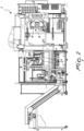
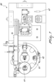
Figure 1 is a top view of the apparatus for the manufacture and unloading of preforms according to the invention; -
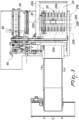
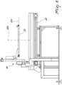
Figure 2 is a side view of the apparatus ofFigure 1 ; -
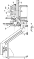
Figure 3 is an enlarged-scale top view of a portion of the cooling and extraction device, in which the selective extraction device is shown in dashed lines in the pickup position and in solid lines proximate to the conveyance position; -
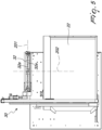
Figure 4 is a side view of the portion shown inFigure 3 ; -
Figure 5 is a top view of the selective extraction device; -
Figure 6 is a side view of the selective extraction device ofFigure 5 ; -
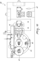
Figure 7 is a top view of the control and inspection device in a first condition; -
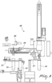
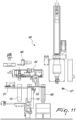
Figure 8 is a front view of the control and inspection device in the condition shown inFigure 7 ; -
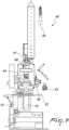
Figure 9 is a side view of the control and inspection device in the condition shown inFigures 7 and8 ; -
Figure 10 is a top view of the control and inspection device in a second condition; -
Figure 11 is a front view of the control and inspection device in the condition shown inFigure 10 ; -
Figure 12 is a side view of the control and inspection device in the condition shown inFigures 10 and11 . - With reference to the figures, the apparatus for the manufacture and unloading of preforms for the manufacture of plastic containers according to the invention, designated generally by the
reference numeral 1, comprises adevice 2 for molding (by injection) a plurality ofpreforms 10 and adevice 3 for cooling and extracting thepreforms 10 from the molding device. - The cooling and
extraction device 3 comprises a grip assembly 4 which forms a plurality of cooling receptacles forrespective preforms 10, and means for the transfer of the still-warm preforms from themolding device 2 to the grip assembly 4. - The cooling and
extraction device 3 further comprises anunloading plate 20, which supports a plurality ofgrip bodies 21 which are arranged in a matrix and can be moved on command in order to engage selectively the grip assembly 4 to allow the extraction of thecooled preforms 10 from the respective receptacle and the unloading onto anunloading surface 22 of thepreforms 10. - According to the present invention, the
apparatus 1 comprises adevice 30 for the selective extraction of apredetermined subset 31 ofpreforms 10 supported by theunloading plate 20 in an orderly manner along at least onepickup direction 201, and means for the orderly transfer of thepredetermined subset 31 ofpreforms 10 to at least one control andinspection device 40 adapted to perform at least one control on thepredetermined subset 31 ofpreforms 10. - The
unloading plate 20 supports a plurality ofgrip bodies 21 which are arranged in a matrix and are arranged along a plurality ofrows 22a and a plurality ofcolumns 22b which are substantially perpendicular to the plurality ofrows 22a. - The
predetermined subset 31 ofpreforms 10 supported by theunloading plate 20 corresponds to thepreforms 10 supported by at least onerow 22a of thegrip bodies 21, or to at least onecolumn 22b of thegrip bodies 21. - Advantageously, the
selective extraction device 30 comprises anelongated body 32 which forms means for supporting the preforms to be extracted. - The
selective extraction device 30 is configured to pick up selectively thepreforms 10 supported bydifferent rows 22a of the grip bodies and/or bydifferent columns 22b of the grip bodies. - Conveniently, the control and
inspection device 40 is associated functionally with means for the movement of theelongated body 32, which are adapted to move theelongated body 32 between a pickup position (shown in broken lines and in phantom lines inFigure 3 ), in which it is arranged proximate to theunloading plate 20 and faces respectively at least onerespective row 22a and/or arespective column 22b, and a position for conveyance substantially at an unloading region which is arranged proximate to aconveyor 50 adapted to send thepreforms 10 in an orderly manner at the control andinspection device 40. - The means for the movement of the
elongated body 32 comprise, for example, linear guides associated with respective actuators in order to allow their movement along amovement direction 202, at least from the pickup position to the conveyance position, and optionally also along adirection 203 which is substantially vertical, so as to be able to program the optimum movement trajectory. - With reference to the practical embodiment shown in the figures, the movement direction can be extended substantially at right angles to the
pickup direction 201. - The
elongated body 32 conveniently comprises a clamp structure to retain, at its mutually facinglongitudinal edges 32a, thepreforms 10. - Conveniently, the control and
inspection device 40 comprises at least one unit chosen from the group comprising: - a top seal inspection unit with
video camera 41; - a bottom inspection unit with
video camera 42; - a body defect inspection unit with
video camera 43; - a PET body stress inspection unit with
video camera 44 using polarized light or a grid; - a thread parting line inspection unit with
video camera 45; - a thread and bottle neck defect inspection unit with
video camera 46; - a preform color inspection unit with
video camera 43; - a unit for detecting the
cavity number 46; - a unit for the measurement of the body and the thread with
video camera 46, including thickness; - a unit for measuring the temperature with a
pyrometer 47; - a
weight control unit 48. - The control and
inspection device 40 further comprises at least one unit chosen in the group comprising: - a unit for measuring thickness with optical sensors;
- a unit for color control with a spectrometer;
- a unit for 3D reconstruction by tomography;
- a unit for acetaldehyde detection by means of an olfactory sensor. The
conveyor 50 is chosen, for example, from the group comprising: - a belt or chain conveyor;
- an air jet conveyor;
- a pair of oppositely rotating rollers.
- The
apparatus 1 comprises, downstream of theconveyor 50, an accumulation system. - A timing system may further be provided downstream of said accumulation system.
- The operation of the
apparatus 1 according to the invention is as follows. - The
selective extraction device 30 and the control andinspection device 40 can be arranged within the space occupations of the molding, cooling and extraction device. - The plastic is injected by means of an extruder into the molding device and is pressed.
- The grip assembly 4 extracts the preforms from the
molding device 2 and, by virtue of known solutions, controls the cooling of thepreforms 10. - The unloading
plate 20 picks up thepreforms 10 from the grip assembly 4 with the task of moving them onto the unloadingsurface 22 constituted by the press extraction belt. Thepreforms 10 are released by the unloadingplate 20 and are conveyed towards the outlet by means of the extraction belt and the extraction belt feeds them into octabins. - The
selective extraction device 30 comprises for example theelongated body 32, which can move along themovement direction 202, in order to convey the extracted preforms 10 to the control andinspection device 40. - The
elongated body 32 may furthermore be moved along the substantiallyvertical direction 203 in order to go to pick up and accommodate thepreform 10 from the unloadingplate 20 in a controlled manner and to release them, again in a controlled manner, to theconveyor 50. - Nothing prevents the possibility to move the
elongated body 32 along a different movement trajectory, constituted for example by the combination of the movement along thedirection 202 and along thedirection 203. - The
elongated body 32 intervenes by picking up the preforms directly from the unloadingplate 20, where they are arranged, as explained, in a matrix which duplicates the matrix of the mold. - The invention, by virtue of the possibility to move the
elongated body 32 in the vicinity of the unloadingplate 20, allows to pick up thepreforms 10 without the risk of causing defects to them during the transfer step. - The
elongated body 32 picks up acolumn 22b and/or arow 22a and/or the entire matrix. Pickup occurs at each molding or at specific time intervals. If the system picks up asingle column 22b or asingle row 22a, it can perform this operation by deciding each time which of the i-th rows 22a or j-th columns 22b to pick up. - It is therefore evident that it is possible to reconstruct the entire matrix of the mold or concentrate the pickups in a predetermined time and therefore the controls on a
single row 22a orcolumn 22b of the matrix, discriminated as potentially critical for any reason, by means of a trigger which can be reported by the automation system or by the control system or by a choice of the operator, with the prospect of increasing its population and therefore its statistical value. - Since it is a control performed by the grip assembly, the reference to the individual cavity of the mold is maintained up to the inside of the control and
inspection device 40, allowing spot control on the individual specific cavity. - The
preforms 10 of thepredetermined subset 31, once they have been picked up from theelongated element 32 and supported by virtue of their geometry, for example supported under the neck, are conveyed, by virtue of the movement along themovement direction 202, to the control andinspection device 40. - The control and
inspection device 40 loads thepreforms 10 by means of theconveyor 50, which is configured to maintain their order and/or orientation. - However, nothing forbids the use of systems that might also not guarantee order and/or orientation.
- If orientation is not maintained, it is possible to perform in any case a rough inspection of the
preforms 10. - Advantageously, the
conveyor 50 can for example comprise two oppositely rotating rollers, which maintain the order and orientation of thepreforms 10 but not their spacing. - This type of roller conveyor allows to feed the
preforms 10 to the control andinspection device 40 without causing defects to saidpreforms 10. For this reason, theconveyor 50 is adapted to tilt by an angle which can also be fixed, allowing thepreforms 10 to form a queue and continue in their flow. - Downstream of the rollers there is an accumulation system with gravity guides, which allows the rollers to return horizontal in the pickup position once the
preforms 10 have been unloaded. - Downstream of the buffer there is a timing system which can be used or not as first inspection tracking.
- The timing system comprises, for example, a
format star conveyor 51 which also acts as first tracking, but it might also be, by way of non-limiting example, a friction feeder or a pair of belts or chains. - The top seal and the bottom of the
preform 10 are inspected along thestar conveyor 51. - In output from the
star conveyor 51, thepreform 10 is handled under the sealing and tamper-evident ring or by means of another characteristic geometry by means of a transfer clamp 52 (which is pneumatic or electric). Thetransfer clamp 52 serves three stations, advantageously transferring two preforms at a time by means of an actuation system constituted by a pneumatic cylinder or by an electric actuator. - The three stations can be for example constituted by a star conveyor extraction device, by a weighing module, which comprises the
weight control unit 48, and a second rotation inspection tracking. - The stations may be just two and the weighing module comprising the
weight control unit 48 can be positioned downstream of the second tracking. - The weighing module comprising the
weight control unit 48 has a plate which supports the preform below the bottle neck (or laid down on the body or below the neck if it is arranged after the second tracking). - Weighing occurs by isolating the weighing module that comprises the
weight control unit 48 in a mechanical or electronic manner from the vibrations of the press. - As a consequence of weighing, the
preform 10 passes to the second tracking, where it is picked up by vacuum (or by means of a clamp). - A movement axis allows to make the
preform 10 translate upward, allowing one ormore pyrometers 47 to detect one or more temperature profiles on the external body of thepreform 10. Onepyrometer 47 might be also positioned within thepreform 10 in order to detect an internal profile. - Once translated into the inspection position, the following are controlled, during a rotation permitted by a dedicated rotation axis, on the preform 10:
- body defect inspection with video camera;
- PET body stress inspection with video camera using polarized light or a grid;
- thread parting line and body inspection with a video camera;
- thread and neck defect inspection with video camera;
- preform color inspection with video camera;
- detection of cavity number;
- measurements of body and thread with video camera, including thickness.
- Detection of the cavity number allows to compare the actual order of arrival of the preforms in the control and
inspection device 40 with the arrangement of the matrix of the mold, identifying any preforms lost in transport and thus reporting a possible problem to the automation system. - During rotation, a circumferential temperature profile can be detected by virtue of the
pyrometer 47. - At this point, the controls on the
preform 10 have been performed and a quality report on theindividual preform 10 is recorded and/or released and the preform is released from the vacuum grip onto a belt which reconnects the flow in the extraction belt into an octabin. If it is identified as defective, it can be rejected or it can continue in the flow of the preforms: this distinction is made by means of appropriate separation means, such as for example a trapdoor, pneumatic devices, etc. which are already known in the art. - If the operator wishes to perform further controls on the preforms (for example destructive controls), by means of said separation means, constituted for example by the trapdoor, he can decide to pick up the preform for sampling.
- If the control and
inspection device 40 detects a certain number of defective preforms that have functional or aesthetic defects, in some conditions it is possible to hypothesize, on the basis of these data, a relatively low overall quality of the preforms contained in a predetermined octabin and consequently report said octabin to assess any subsequent interventions. - The control and
inspection device 40 can be configured to control a series of parameters adapted to verify for example a "trend" of theapparatus 1, or of some parts thereof, which can generate a signal to the operator without thereby entailing the rejection of the controlledpreforms 10. - For example, if the control and
inspection device 40 detects that in thepreforms 10 manufactured in a predetermined cavity the temperature or one dimension slowly tend to deviate (while remaining within the conformity range), the inspection andcontrol device 40 might report and recommend a check of said cavity during the subsequent intervention with machine downtime, also with the prospect, therefore, of preventive/predictive maintenance. - The control and
inspection device 40 can also be used as a system for the quick sampling of the preforms by means of a dedicated cycle that can be selected in an interface which speeds up extraction and excludes inspection, allowing immediate control by the operator and without contaminations. - The samplings can be also used to check the calibration of the device by means of bench tests. Sampling again occurs by means of the rejection trapdoor, which directs the flow into a box that can be extracted from a window.
- The application is particularly useful for process control, since it does not introduce defectiveness on the product. This means that the defects and measurements performed by the control system relate exclusively to the process of the press.
- Furthermore, contamination, for example sweat, on the part of the operator does not occur, since everything is automated.
- Furthermore, it allows to detect product temperature by means of a pyrometer in a few seconds and in a manner that is repeatable over time, allowing actual control of the exit temperature for each cavity.
- The inspection system can also be installed as a retrofit kit, i.e., as an additional device that can be installed on already operational systems.
- All the values detected by the system can be attributed to each individual cavity. This allows to feedback this information on the press and to fix possible drifts for each individual cavity.
- As an alternative, it is possible to correlate this information with certain parameters and perform or predictive interventions or maintenance, or calculate trends correlated with certain parameters.
- The area in which the control and inspection device is located can have isolated access with respect to the molding device.
- This allows to have parallel efficiencies between the two machines, and therefore the efficiency of the control and inspection device does not affect the efficiency of press.
- It is furthermore possible to act to solve jamming situations or problems of the control and inspection device and on the clamp for extraction from the unloading plate while the molding device is turned on.
- The separation between the two areas can occur by means of safety distances which render access safe, by means of a separation with photoelectric barriers or by means of a separation with an actuated partition or other systems that are known in the art.
- In practice it has been found that the invention achieves the intended aim and objects.
- The invention thus conceived is susceptible of numerous modifications and variations, all of which are within the scope of the appended claims.
- Thus, for example, it is also possible to provide that the unloading
plate 20, by means of adjustment devices, can directly pick up apredetermined subset 31 of preforms 10 (for example one ormore rows 22a and/or one ormore columns 22b) in order to send them to the control andinspection device 40. - Where technical features mentioned in any claim are followed by reference signs, those reference signs have been included for the sole purpose of increasing the intelligibility of the claims and accordingly such reference signs do not have any limiting effect on the interpretation of each element identified by way of example by such reference signs.
Claims (13)
- An apparatus (1) for the manufacture and unloading of preforms (10) for the manufacture of plastic containers, comprising a device (2) for the injection molding of a plurality of preforms (10) and a device (3) for the cooling and extraction of the preforms (10) from said molding device (2), said cooling and extraction device (3) comprising a grip assembly (4) which forms a plurality of cooling receptacles for respective preforms (10), means being provided for transferring the still-warm preforms from said molding device to said grip assembly (4), said cooling and extraction device (3) comprising an unloading plate (20) which supports a plurality of grip bodies (21) which are arranged in a matrix and can be moved on command in order to engage selectively said grip assembly (4) in order to allow the extraction of the cooled preforms (10) from the respective receptacle and the unloading onto an unloading surface (22) of the preforms (10), characterized in that it comprises a device (30) for the selective extraction of a predetermined subset (31) of preforms (10) supported by said unloading plate (20) in an orderly manner along at least one pickup direction (201), and means for the orderly transfer of said predetermined subset (31) of preforms (10) to at least one control and inspection device (40) adapted to perform at least one control on said predetermined subset (31) of preforms (10).
- The apparatus according to claim 1, characterized in that said unloading plate (20) supports a plurality of grip bodies (21) which are arranged in a matrix along a plurality of rows (22a) and a plurality of columns (22b) which are substantially perpendicular to said plurality of rows, said predetermined subset (31) of preforms supported by said unloading plate (20) corresponding to the preforms (10) supported by at least one row (22a) of said grip bodies (21) or to at least one column (22b) of said grip bodies (21).
- The apparatus (1) according to one or more of the preceding claims, characterized in that said selective extraction device (30) comprises an elongated body (32) which forms supporting means for the preforms (10) to be extracted, said selective extraction device (30) being configured to pick up selectively the supported preforms (10) from different rows (22a) of said grip bodies (21) and/or from different columns (22b) of grip bodies (21).
- The apparatus (1) according to one or more of the preceding claims, characterized in that said control and inspection device (40) is functionally associated with means for moving said elongated body (32) which are adapted to move said elongated body (32) between a pickup position proximate to said unloading plate (20) and facing respectively at least one respective row (22a) and/or a respective column (22b), and a conveyance position substantially at an unloading region arranged proximate to a conveyor (50) adapted to send said preforms (10) in an orderly manner at said control and inspection device (40).
- The apparatus (1) according to one or more of the preceding claims, characterized in that said control and inspection device (40) comprises at least one unit chosen in the group comprising:- a top seal inspection unit with video camera (41);- a bottom inspection unit with video camera (42);- a body defect inspection unit with video camera (43);- a PET body stress inspection unit with video camera (44) using polarized light or a grid;- a thread parting line inspection unit with video camera (45);- a thread and bottle neck defect inspection unit with video camera (46);- a preform color inspection unit with video camera;- a unit for detecting the cavity number (46);- a unit for the measurement of the body and the thread with video camera, including thickness;- a unit for measuring the temperature with a pyrometer (47);- a weight control unit (48).
- The apparatus (1) according to one or more of the preceding claims, characterized in that said control and inspection device (40) further comprises at least one unit chosen from the group comprising:- a unit for measuring thickness with optical sensors;- a unit for color control with a spectrometer;- a unit for 3D reconstruction by tomography;- a unit for acetaldehyde detection by means of an olfactory sensor.
- The apparatus (1) according to one or more of the preceding claims, characterized in that said conveyor is chosen in the group comprising:- a belt or chain conveyor;- an air jet conveyor;- a pair of oppositely rotating rollers.
- The apparatus (1) according to one or more of the preceding claims, characterized in that it comprises, downstream of said conveyor (50), an accumulation system.
- The apparatus (1) according to one or more of the preceding claims, characterized in that it comprises, downstream of said accumulation system, a timing system.
- The apparatus (1) according to one or more of the preceding claims, characterized in that said control and inspection device (40) comprises a clamp (52) for transfer to three stations, the second station comprising a weighing module, which comprises said weight control unit (48).
- The apparatus (1) according to one or more of the preceding claims, characterized in that said at least one pyrometer (47) is associated with a respective movement axis which is adapted to allow a relative movement between said at least one pyrometer (47) and said preform, so as to detect at least one temperature profile of said preform (10) along the axis of extension of said preform (10).
- The apparatus (1) according to one or more of the preceding claims, characterized in that it comprises means for the movement, about a rotation axis, of said preform (10) with respect to said at least one unit in order to perform inspections during rotation and/or detect the temperature profile on the circumference of said preform (10).
- The apparatus (1) according to one or more of the preceding claims, characterized in that the area in which said control and inspection device (40) is arranged has an access which is isolated with respect to the access of said molding device.
Applications Claiming Priority (1)
| Application Number | Priority Date | Filing Date | Title |
|---|---|---|---|
| IT202100026723 | 2021-10-19 |
Publications (2)
| Publication Number | Publication Date |
|---|---|
| EP4169692A1 EP4169692A1 (en) | 2023-04-26 |
| EP4169692B1 true EP4169692B1 (en) | 2024-06-12 |
Family
ID=79164609
Family Applications (1)
| Application Number | Title | Priority Date | Filing Date |
|---|---|---|---|
| EP22196905.8A Active EP4169692B1 (en) | 2021-10-19 | 2022-09-21 | Apparatus for the manufacture and unloading of preforms for the manufacture of plastic containers |
Country Status (7)
| Country | Link |
|---|---|
| US (1) | US12042969B2 (en) |
| EP (1) | EP4169692B1 (en) |
| JP (1) | JP2023061898A (en) |
| CN (1) | CN115990975A (en) |
| CA (1) | CA3178493A1 (en) |
| ES (1) | ES2984107T3 (en) |
| TW (1) | TW202327849A (en) |
Families Citing this family (6)
| Publication number | Priority date | Publication date | Assignee | Title |
|---|---|---|---|---|
| US20240068807A1 (en) * | 2022-08-23 | 2024-02-29 | Goodrich Corporation | Real-time preform material thickness measurement |
| JP2024127205A (en) * | 2023-03-09 | 2024-09-20 | セイコーエプソン株式会社 | Injection Molding System |
| DE102023119038A1 (en) * | 2023-07-19 | 2025-01-23 | Krones Aktiengesellschaft | Coupling of injection molding machine and stretch blow molding machine via air transport |
| DE102024101048A1 (en) | 2024-01-15 | 2025-07-17 | Krones Aktiengesellschaft | Device and method for producing plastic preforms with infrared image recording device |
| DE102024101049A1 (en) * | 2024-01-15 | 2025-07-17 | Krones Aktiengesellschaft | Apparatus and method for producing plastic preforms with control of the production units depending on inspection results |
| WO2025233828A1 (en) | 2024-05-06 | 2025-11-13 | Sacmi Cooperativa Meccanici Imola Societa' Cooperativa | Apparatus and method for the manufacture of parisons intended for blow moulding to form containers |
Family Cites Families (6)
| Publication number | Priority date | Publication date | Assignee | Title |
|---|---|---|---|---|
| ITRM20030460A1 (en) * | 2003-10-07 | 2005-04-08 | Sipa Societa Industrializzazione P Rogettazione A | DEVICE AND PROCESS OF INJECTION OF PLASTIC OBJECTS. |
| EP3169507B1 (en) * | 2014-07-17 | 2025-01-08 | Sacmi Imola S.C. | Device for unloading and storing preforms for the production of containers made of plastics |
| GB2528934B (en) * | 2014-08-05 | 2017-08-02 | Colton William | Preform Optical Inspection |
| CH712830A2 (en) * | 2016-08-23 | 2018-02-28 | Finatec Holding Ag | Optical inspection system for hollow bodies, in particular preforms. |
| WO2018072009A1 (en) * | 2016-10-17 | 2018-04-26 | Husky Injection Molding Systems Ltd. | Molding system and method of inspecting multilayer preforms |
| IT202000002722A1 (en) * | 2020-02-12 | 2021-08-12 | Sacmi Imola Sc | DEVICE FOR COOLING AND EXTRACTION OF PREFORMS FOR THE PRODUCTION OF PLASTIC CONTAINERS. |
-
2022
- 2022-09-21 EP EP22196905.8A patent/EP4169692B1/en active Active
- 2022-09-21 ES ES22196905T patent/ES2984107T3/en active Active
- 2022-10-03 JP JP2022159495A patent/JP2023061898A/en active Pending
- 2022-10-06 US US17/938,479 patent/US12042969B2/en active Active
- 2022-10-06 CA CA3178493A patent/CA3178493A1/en active Pending
- 2022-10-18 CN CN202211273359.7A patent/CN115990975A/en active Pending
- 2022-10-19 TW TW111139618A patent/TW202327849A/en unknown
Also Published As
| Publication number | Publication date |
|---|---|
| JP2023061898A (en) | 2023-05-02 |
| CN115990975A (en) | 2023-04-21 |
| US12042969B2 (en) | 2024-07-23 |
| EP4169692A1 (en) | 2023-04-26 |
| TW202327849A (en) | 2023-07-16 |
| CA3178493A1 (en) | 2023-04-19 |
| ES2984107T3 (en) | 2024-10-28 |
| US20230124802A1 (en) | 2023-04-20 |
Similar Documents
| Publication | Publication Date | Title |
|---|---|---|
| US12042969B2 (en) | Apparatus for the manufacture and unloading of preforms for the manufacture of plastic containers | |
| EP2743689B1 (en) | Method and apparatus for inspecting glass products during the production | |
| US10160559B2 (en) | Cigarette package coding system and associated method | |
| US9271505B2 (en) | Apparatus for conveying, inspecting and stacking items | |
| EP3177911A1 (en) | An optical inspection system | |
| KR20110028240A (en) | Apparatus and method for checking container closures | |
| EP4132763B1 (en) | Device and method for inspecting parisons | |
| US7671620B2 (en) | Testing system for solar cells | |
| KR101980860B1 (en) | A spring pin separating apparatus | |
| PL175840B1 (en) | Method of and system for sorting containers | |
| CN1139476C (en) | Device and method for producing plastic hollow bodies | |
| WO2012001414A2 (en) | Inspection | |
| EP3513174B1 (en) | Inspection device and method for parisons and machine for making parisons comprising the device | |
| JP2022538614A (en) | Device for optical inspection of preforms | |
| RU2714952C1 (en) | Device for processing fruit-growing products, such as blueberries and similar | |
| CN111002109B (en) | High-flexibility continuous composite automatic production system suitable for flaky materials | |
| US8137090B2 (en) | Device for producing nuclear fuel pellets and production method applying such a device | |
| JP3417487B2 (en) | Cap mounting failure detection method and device | |
| CN108423405B (en) | Betel nut dishing is with discernment linkage sensing device and betel nut dishing mechanism | |
| CN220635386U (en) | Visual inspection equipment | |
| CN223788988U (en) | A bottle cap inner plug testing mechanism | |
| US20210158505A1 (en) | Inspection system | |
| JP4815244B2 (en) | Bottle inspection machine and bottle making equipment | |
| CA3144867C (en) | Device for optical inspection of preforms | |
| CN114871156A (en) | Tail material box, blanking sorting equipment and sorting system |
Legal Events
| Date | Code | Title | Description |
|---|---|---|---|
| PUAI | Public reference made under article 153(3) epc to a published international application that has entered the european phase |
Free format text: ORIGINAL CODE: 0009012 |
|
| STAA | Information on the status of an ep patent application or granted ep patent |
Free format text: STATUS: THE APPLICATION HAS BEEN PUBLISHED |
|
| AK | Designated contracting states |
Kind code of ref document: A1 Designated state(s): AL AT BE BG CH CY CZ DE DK EE ES FI FR GB GR HR HU IE IS IT LI LT LU LV MC MK MT NL NO PL PT RO RS SE SI SK SM TR |
|
| P01 | Opt-out of the competence of the unified patent court (upc) registered |
Effective date: 20230529 |
|
| STAA | Information on the status of an ep patent application or granted ep patent |
Free format text: STATUS: REQUEST FOR EXAMINATION WAS MADE |
|
| 17P | Request for examination filed |
Effective date: 20230802 |
|
| RBV | Designated contracting states (corrected) |
Designated state(s): AL AT BE BG CH CY CZ DE DK EE ES FI FR GB GR HR HU IE IS IT LI LT LU LV MC MK MT NL NO PL PT RO RS SE SI SK SM TR |
|
| GRAP | Despatch of communication of intention to grant a patent |
Free format text: ORIGINAL CODE: EPIDOSNIGR1 |
|
| STAA | Information on the status of an ep patent application or granted ep patent |
Free format text: STATUS: GRANT OF PATENT IS INTENDED |
|
| RIC1 | Information provided on ipc code assigned before grant |
Ipc: B29C 45/72 20060101ALN20231212BHEP Ipc: B29C 49/06 20060101ALI20231212BHEP Ipc: B29C 49/78 20060101ALI20231212BHEP Ipc: B29C 49/64 20060101ALI20231212BHEP Ipc: B29C 45/42 20060101ALI20231212BHEP Ipc: B29C 45/17 20060101AFI20231212BHEP |
|
| INTG | Intention to grant announced |
Effective date: 20240108 |
|
| GRAS | Grant fee paid |
Free format text: ORIGINAL CODE: EPIDOSNIGR3 |
|
| GRAA | (expected) grant |
Free format text: ORIGINAL CODE: 0009210 |
|
| STAA | Information on the status of an ep patent application or granted ep patent |
Free format text: STATUS: THE PATENT HAS BEEN GRANTED |
|
| AK | Designated contracting states |
Kind code of ref document: B1 Designated state(s): AL AT BE BG CH CY CZ DE DK EE ES FI FR GB GR HR HU IE IS IT LI LT LU LV MC MK MT NL NO PL PT RO RS SE SI SK SM TR |
|
| REG | Reference to a national code |
Ref country code: GB Ref legal event code: FG4D |
|
| REG | Reference to a national code |
Ref country code: CH Ref legal event code: EP |
|
| REG | Reference to a national code |
Ref country code: IE Ref legal event code: FG4D |
|
| REG | Reference to a national code |
Ref country code: DE Ref legal event code: R096 Ref document number: 602022003918 Country of ref document: DE |
|
| PG25 | Lapsed in a contracting state [announced via postgrant information from national office to epo] |
Ref country code: BG Free format text: LAPSE BECAUSE OF FAILURE TO SUBMIT A TRANSLATION OF THE DESCRIPTION OR TO PAY THE FEE WITHIN THE PRESCRIBED TIME-LIMIT Effective date: 20240612 |
|
| PG25 | Lapsed in a contracting state [announced via postgrant information from national office to epo] |
Ref country code: FI Free format text: LAPSE BECAUSE OF FAILURE TO SUBMIT A TRANSLATION OF THE DESCRIPTION OR TO PAY THE FEE WITHIN THE PRESCRIBED TIME-LIMIT Effective date: 20240612 Ref country code: HR Free format text: LAPSE BECAUSE OF FAILURE TO SUBMIT A TRANSLATION OF THE DESCRIPTION OR TO PAY THE FEE WITHIN THE PRESCRIBED TIME-LIMIT Effective date: 20240612 |
|
| REG | Reference to a national code |
Ref country code: LT Ref legal event code: MG9D |
|
| PG25 | Lapsed in a contracting state [announced via postgrant information from national office to epo] |
Ref country code: GR Free format text: LAPSE BECAUSE OF FAILURE TO SUBMIT A TRANSLATION OF THE DESCRIPTION OR TO PAY THE FEE WITHIN THE PRESCRIBED TIME-LIMIT Effective date: 20240913 |
|
| REG | Reference to a national code |
Ref country code: NL Ref legal event code: MP Effective date: 20240612 |
|
| REG | Reference to a national code |
Ref country code: ES Ref legal event code: FG2A Ref document number: 2984107 Country of ref document: ES Kind code of ref document: T3 Effective date: 20241028 |
|
| PG25 | Lapsed in a contracting state [announced via postgrant information from national office to epo] |
Ref country code: LV Free format text: LAPSE BECAUSE OF FAILURE TO SUBMIT A TRANSLATION OF THE DESCRIPTION OR TO PAY THE FEE WITHIN THE PRESCRIBED TIME-LIMIT Effective date: 20240612 |
|
| PG25 | Lapsed in a contracting state [announced via postgrant information from national office to epo] |
Ref country code: NO Free format text: LAPSE BECAUSE OF FAILURE TO SUBMIT A TRANSLATION OF THE DESCRIPTION OR TO PAY THE FEE WITHIN THE PRESCRIBED TIME-LIMIT Effective date: 20240912 Ref country code: LV Free format text: LAPSE BECAUSE OF FAILURE TO SUBMIT A TRANSLATION OF THE DESCRIPTION OR TO PAY THE FEE WITHIN THE PRESCRIBED TIME-LIMIT Effective date: 20240612 Ref country code: HR Free format text: LAPSE BECAUSE OF FAILURE TO SUBMIT A TRANSLATION OF THE DESCRIPTION OR TO PAY THE FEE WITHIN THE PRESCRIBED TIME-LIMIT Effective date: 20240612 Ref country code: GR Free format text: LAPSE BECAUSE OF FAILURE TO SUBMIT A TRANSLATION OF THE DESCRIPTION OR TO PAY THE FEE WITHIN THE PRESCRIBED TIME-LIMIT Effective date: 20240913 Ref country code: FI Free format text: LAPSE BECAUSE OF FAILURE TO SUBMIT A TRANSLATION OF THE DESCRIPTION OR TO PAY THE FEE WITHIN THE PRESCRIBED TIME-LIMIT Effective date: 20240612 Ref country code: BG Free format text: LAPSE BECAUSE OF FAILURE TO SUBMIT A TRANSLATION OF THE DESCRIPTION OR TO PAY THE FEE WITHIN THE PRESCRIBED TIME-LIMIT Effective date: 20240612 Ref country code: RS Free format text: LAPSE BECAUSE OF FAILURE TO SUBMIT A TRANSLATION OF THE DESCRIPTION OR TO PAY THE FEE WITHIN THE PRESCRIBED TIME-LIMIT Effective date: 20240912 |
|
| PG25 | Lapsed in a contracting state [announced via postgrant information from national office to epo] |
Ref country code: NL Free format text: LAPSE BECAUSE OF FAILURE TO SUBMIT A TRANSLATION OF THE DESCRIPTION OR TO PAY THE FEE WITHIN THE PRESCRIBED TIME-LIMIT Effective date: 20240612 |
|
| PG25 | Lapsed in a contracting state [announced via postgrant information from national office to epo] |
Ref country code: NL Free format text: LAPSE BECAUSE OF FAILURE TO SUBMIT A TRANSLATION OF THE DESCRIPTION OR TO PAY THE FEE WITHIN THE PRESCRIBED TIME-LIMIT Effective date: 20240612 |
|
| PG25 | Lapsed in a contracting state [announced via postgrant information from national office to epo] |
Ref country code: PT Free format text: LAPSE BECAUSE OF FAILURE TO SUBMIT A TRANSLATION OF THE DESCRIPTION OR TO PAY THE FEE WITHIN THE PRESCRIBED TIME-LIMIT Effective date: 20241014 |
|
| PG25 | Lapsed in a contracting state [announced via postgrant information from national office to epo] |
Ref country code: PT Free format text: LAPSE BECAUSE OF FAILURE TO SUBMIT A TRANSLATION OF THE DESCRIPTION OR TO PAY THE FEE WITHIN THE PRESCRIBED TIME-LIMIT Effective date: 20241014 |
|
| PG25 | Lapsed in a contracting state [announced via postgrant information from national office to epo] |
Ref country code: PL Free format text: LAPSE BECAUSE OF FAILURE TO SUBMIT A TRANSLATION OF THE DESCRIPTION OR TO PAY THE FEE WITHIN THE PRESCRIBED TIME-LIMIT Effective date: 20240612 |
|
| PG25 | Lapsed in a contracting state [announced via postgrant information from national office to epo] |
Ref country code: EE Free format text: LAPSE BECAUSE OF FAILURE TO SUBMIT A TRANSLATION OF THE DESCRIPTION OR TO PAY THE FEE WITHIN THE PRESCRIBED TIME-LIMIT Effective date: 20240612 |
|
| PG25 | Lapsed in a contracting state [announced via postgrant information from national office to epo] |
Ref country code: IS Free format text: LAPSE BECAUSE OF FAILURE TO SUBMIT A TRANSLATION OF THE DESCRIPTION OR TO PAY THE FEE WITHIN THE PRESCRIBED TIME-LIMIT Effective date: 20241012 |
|
| PG25 | Lapsed in a contracting state [announced via postgrant information from national office to epo] |
Ref country code: CZ Free format text: LAPSE BECAUSE OF FAILURE TO SUBMIT A TRANSLATION OF THE DESCRIPTION OR TO PAY THE FEE WITHIN THE PRESCRIBED TIME-LIMIT Effective date: 20240612 |
|
| PG25 | Lapsed in a contracting state [announced via postgrant information from national office to epo] |
Ref country code: RO Free format text: LAPSE BECAUSE OF FAILURE TO SUBMIT A TRANSLATION OF THE DESCRIPTION OR TO PAY THE FEE WITHIN THE PRESCRIBED TIME-LIMIT Effective date: 20240612 Ref country code: SK Free format text: LAPSE BECAUSE OF FAILURE TO SUBMIT A TRANSLATION OF THE DESCRIPTION OR TO PAY THE FEE WITHIN THE PRESCRIBED TIME-LIMIT Effective date: 20240612 |
|
| PG25 | Lapsed in a contracting state [announced via postgrant information from national office to epo] |
Ref country code: SM Free format text: LAPSE BECAUSE OF FAILURE TO SUBMIT A TRANSLATION OF THE DESCRIPTION OR TO PAY THE FEE WITHIN THE PRESCRIBED TIME-LIMIT Effective date: 20240612 |
|
| PG25 | Lapsed in a contracting state [announced via postgrant information from national office to epo] |
Ref country code: SM Free format text: LAPSE BECAUSE OF FAILURE TO SUBMIT A TRANSLATION OF THE DESCRIPTION OR TO PAY THE FEE WITHIN THE PRESCRIBED TIME-LIMIT Effective date: 20240612 Ref country code: SK Free format text: LAPSE BECAUSE OF FAILURE TO SUBMIT A TRANSLATION OF THE DESCRIPTION OR TO PAY THE FEE WITHIN THE PRESCRIBED TIME-LIMIT Effective date: 20240612 Ref country code: RO Free format text: LAPSE BECAUSE OF FAILURE TO SUBMIT A TRANSLATION OF THE DESCRIPTION OR TO PAY THE FEE WITHIN THE PRESCRIBED TIME-LIMIT Effective date: 20240612 Ref country code: PL Free format text: LAPSE BECAUSE OF FAILURE TO SUBMIT A TRANSLATION OF THE DESCRIPTION OR TO PAY THE FEE WITHIN THE PRESCRIBED TIME-LIMIT Effective date: 20240612 Ref country code: IS Free format text: LAPSE BECAUSE OF FAILURE TO SUBMIT A TRANSLATION OF THE DESCRIPTION OR TO PAY THE FEE WITHIN THE PRESCRIBED TIME-LIMIT Effective date: 20241012 Ref country code: EE Free format text: LAPSE BECAUSE OF FAILURE TO SUBMIT A TRANSLATION OF THE DESCRIPTION OR TO PAY THE FEE WITHIN THE PRESCRIBED TIME-LIMIT Effective date: 20240612 Ref country code: CZ Free format text: LAPSE BECAUSE OF FAILURE TO SUBMIT A TRANSLATION OF THE DESCRIPTION OR TO PAY THE FEE WITHIN THE PRESCRIBED TIME-LIMIT Effective date: 20240612 |
|
| REG | Reference to a national code |
Ref country code: DE Ref legal event code: R097 Ref document number: 602022003918 Country of ref document: DE |
|
| PG25 | Lapsed in a contracting state [announced via postgrant information from national office to epo] |
Ref country code: DK Free format text: LAPSE BECAUSE OF FAILURE TO SUBMIT A TRANSLATION OF THE DESCRIPTION OR TO PAY THE FEE WITHIN THE PRESCRIBED TIME-LIMIT Effective date: 20240612 |
|
| PLBE | No opposition filed within time limit |
Free format text: ORIGINAL CODE: 0009261 |
|
| STAA | Information on the status of an ep patent application or granted ep patent |
Free format text: STATUS: NO OPPOSITION FILED WITHIN TIME LIMIT |
|
| PG25 | Lapsed in a contracting state [announced via postgrant information from national office to epo] |
Ref country code: MC Free format text: LAPSE BECAUSE OF FAILURE TO SUBMIT A TRANSLATION OF THE DESCRIPTION OR TO PAY THE FEE WITHIN THE PRESCRIBED TIME-LIMIT Effective date: 20240612 |
|
| PG25 | Lapsed in a contracting state [announced via postgrant information from national office to epo] |
Ref country code: LU Free format text: LAPSE BECAUSE OF NON-PAYMENT OF DUE FEES Effective date: 20240921 |
|
| 26N | No opposition filed |
Effective date: 20250313 |
|
| REG | Reference to a national code |
Ref country code: BE Ref legal event code: MM Effective date: 20240930 |
|
| PG25 | Lapsed in a contracting state [announced via postgrant information from national office to epo] |
Ref country code: BE Free format text: LAPSE BECAUSE OF NON-PAYMENT OF DUE FEES Effective date: 20240930 |
|
| PG25 | Lapsed in a contracting state [announced via postgrant information from national office to epo] |
Ref country code: IE Free format text: LAPSE BECAUSE OF NON-PAYMENT OF DUE FEES Effective date: 20240921 |
|
| PG25 | Lapsed in a contracting state [announced via postgrant information from national office to epo] |
Ref country code: SE Free format text: LAPSE BECAUSE OF FAILURE TO SUBMIT A TRANSLATION OF THE DESCRIPTION OR TO PAY THE FEE WITHIN THE PRESCRIBED TIME-LIMIT Effective date: 20240612 |
|
| REG | Reference to a national code |
Ref country code: CH Ref legal event code: U11 Free format text: ST27 STATUS EVENT CODE: U-0-0-U10-U11 (AS PROVIDED BY THE NATIONAL OFFICE) Effective date: 20251001 |
|
| PGFP | Annual fee paid to national office [announced via postgrant information from national office to epo] |
Ref country code: DE Payment date: 20250820 Year of fee payment: 4 |
|
| PGFP | Annual fee paid to national office [announced via postgrant information from national office to epo] |
Ref country code: AT Payment date: 20251020 Year of fee payment: 4 Ref country code: FR Payment date: 20250820 Year of fee payment: 4 |
|
| PGFP | Annual fee paid to national office [announced via postgrant information from national office to epo] |
Ref country code: IT Payment date: 20250930 Year of fee payment: 4 |
|
| PGFP | Annual fee paid to national office [announced via postgrant information from national office to epo] |
Ref country code: CH Payment date: 20251001 Year of fee payment: 4 |
|
| PG25 | Lapsed in a contracting state [announced via postgrant information from national office to epo] |
Ref country code: CY Free format text: LAPSE BECAUSE OF FAILURE TO SUBMIT A TRANSLATION OF THE DESCRIPTION OR TO PAY THE FEE WITHIN THE PRESCRIBED TIME-LIMIT; INVALID AB INITIO Effective date: 20220921 |
|
| PGFP | Annual fee paid to national office [announced via postgrant information from national office to epo] |
Ref country code: ES Payment date: 20251001 Year of fee payment: 4 |
|
| PG25 | Lapsed in a contracting state [announced via postgrant information from national office to epo] |
Ref country code: HU Free format text: LAPSE BECAUSE OF FAILURE TO SUBMIT A TRANSLATION OF THE DESCRIPTION OR TO PAY THE FEE WITHIN THE PRESCRIBED TIME-LIMIT; INVALID AB INITIO Effective date: 20220921 |