EP4169663A1 - Cutting insert and method for manufacturing cutting insert - Google Patents
Cutting insert and method for manufacturing cutting insert Download PDFInfo
- Publication number
- EP4169663A1 EP4169663A1 EP20940838.4A EP20940838A EP4169663A1 EP 4169663 A1 EP4169663 A1 EP 4169663A1 EP 20940838 A EP20940838 A EP 20940838A EP 4169663 A1 EP4169663 A1 EP 4169663A1
- Authority
- EP
- European Patent Office
- Prior art keywords
- cutting
- protrusion
- divided
- substrate
- top surface
- Prior art date
- Legal status (The legal status is an assumption and is not a legal conclusion. Google has not performed a legal analysis and makes no representation as to the accuracy of the status listed.)
- Granted
Links
Images



Classifications
-
- B—PERFORMING OPERATIONS; TRANSPORTING
- B23—MACHINE TOOLS; METAL-WORKING NOT OTHERWISE PROVIDED FOR
- B23P—METAL-WORKING NOT OTHERWISE PROVIDED FOR; COMBINED OPERATIONS; UNIVERSAL MACHINE TOOLS
- B23P15/00—Making specific metal objects by operations not covered by a single other subclass or a group in this subclass
- B23P15/28—Making specific metal objects by operations not covered by a single other subclass or a group in this subclass cutting tools
-
- B—PERFORMING OPERATIONS; TRANSPORTING
- B23—MACHINE TOOLS; METAL-WORKING NOT OTHERWISE PROVIDED FOR
- B23B—TURNING; BORING
- B23B27/00—Tools for turning or boring machines; Tools of a similar kind in general; Accessories therefor
- B23B27/14—Cutting tools of which the bits or tips or cutting inserts are of special material
- B23B27/16—Cutting tools of which the bits or tips or cutting inserts are of special material with exchangeable cutting bits or cutting inserts, e.g. able to be clamped
- B23B27/1603—Cutting tools of which the bits or tips or cutting inserts are of special material with exchangeable cutting bits or cutting inserts, e.g. able to be clamped with specially shaped plate-like exchangeable cutting inserts, e.g. chip-breaking groove
- B23B27/1611—Cutting tools of which the bits or tips or cutting inserts are of special material with exchangeable cutting bits or cutting inserts, e.g. able to be clamped with specially shaped plate-like exchangeable cutting inserts, e.g. chip-breaking groove characterised by having a special shape
-
- B—PERFORMING OPERATIONS; TRANSPORTING
- B23—MACHINE TOOLS; METAL-WORKING NOT OTHERWISE PROVIDED FOR
- B23B—TURNING; BORING
- B23B27/00—Tools for turning or boring machines; Tools of a similar kind in general; Accessories therefor
- B23B27/14—Cutting tools of which the bits or tips or cutting inserts are of special material
- B23B27/141—Specially shaped plate-like cutting inserts, i.e. length greater or equal to width, width greater than or equal to thickness
- B23B27/145—Specially shaped plate-like cutting inserts, i.e. length greater or equal to width, width greater than or equal to thickness characterised by having a special shape
-
- B—PERFORMING OPERATIONS; TRANSPORTING
- B23—MACHINE TOOLS; METAL-WORKING NOT OTHERWISE PROVIDED FOR
- B23B—TURNING; BORING
- B23B27/00—Tools for turning or boring machines; Tools of a similar kind in general; Accessories therefor
- B23B27/14—Cutting tools of which the bits or tips or cutting inserts are of special material
- B23B27/18—Cutting tools of which the bits or tips or cutting inserts are of special material with cutting bits or tips or cutting inserts rigidly mounted, e.g. by brazing
- B23B27/20—Cutting tools of which the bits or tips or cutting inserts are of special material with cutting bits or tips or cutting inserts rigidly mounted, e.g. by brazing with diamond bits or cutting inserts
-
- B—PERFORMING OPERATIONS; TRANSPORTING
- B23—MACHINE TOOLS; METAL-WORKING NOT OTHERWISE PROVIDED FOR
- B23C—MILLING
- B23C5/00—Milling-cutters
- B23C5/16—Milling-cutters characterised by physical features other than shape
- B23C5/20—Milling-cutters characterised by physical features other than shape with removable cutter bits or teeth or cutting inserts
- B23C5/202—Plate-like cutting inserts with special form
-
- B—PERFORMING OPERATIONS; TRANSPORTING
- B23—MACHINE TOOLS; METAL-WORKING NOT OTHERWISE PROVIDED FOR
- B23K—SOLDERING OR UNSOLDERING; WELDING; CLADDING OR PLATING BY SOLDERING OR WELDING; CUTTING BY APPLYING HEAT LOCALLY, e.g. FLAME CUTTING; WORKING BY LASER BEAM
- B23K1/00—Soldering, e.g. brazing, or unsoldering
- B23K1/0008—Soldering, e.g. brazing, or unsoldering specially adapted for particular articles or work
-
- B—PERFORMING OPERATIONS; TRANSPORTING
- B23—MACHINE TOOLS; METAL-WORKING NOT OTHERWISE PROVIDED FOR
- B23K—SOLDERING OR UNSOLDERING; WELDING; CLADDING OR PLATING BY SOLDERING OR WELDING; CUTTING BY APPLYING HEAT LOCALLY, e.g. FLAME CUTTING; WORKING BY LASER BEAM
- B23K1/00—Soldering, e.g. brazing, or unsoldering
- B23K1/008—Soldering within a furnace
-
- B—PERFORMING OPERATIONS; TRANSPORTING
- B23—MACHINE TOOLS; METAL-WORKING NOT OTHERWISE PROVIDED FOR
- B23K—SOLDERING OR UNSOLDERING; WELDING; CLADDING OR PLATING BY SOLDERING OR WELDING; CUTTING BY APPLYING HEAT LOCALLY, e.g. FLAME CUTTING; WORKING BY LASER BEAM
- B23K31/00—Processes relevant to this subclass, specially adapted for particular articles or purposes, but not covered by any single one of main groups B23K1/00 - B23K28/00
- B23K31/02—Processes relevant to this subclass, specially adapted for particular articles or purposes, but not covered by any single one of main groups B23K1/00 - B23K28/00 relating to soldering or welding
- B23K31/025—Connecting cutting edges or the like to tools; Attaching reinforcements to workpieces, e.g. wear-resisting zones to tableware
-
- B—PERFORMING OPERATIONS; TRANSPORTING
- B23—MACHINE TOOLS; METAL-WORKING NOT OTHERWISE PROVIDED FOR
- B23B—TURNING; BORING
- B23B2200/00—Details of cutting inserts
- B23B2200/04—Overall shape
- B23B2200/0471—Square
- B23B2200/0476—Square rounded
-
- B—PERFORMING OPERATIONS; TRANSPORTING
- B23—MACHINE TOOLS; METAL-WORKING NOT OTHERWISE PROVIDED FOR
- B23B—TURNING; BORING
- B23B2226/00—Materials of tools or workpieces not comprising a metal
- B23B2226/12—Boron nitride
- B23B2226/125—Boron nitride cubic [CBN]
-
- B—PERFORMING OPERATIONS; TRANSPORTING
- B23—MACHINE TOOLS; METAL-WORKING NOT OTHERWISE PROVIDED FOR
- B23B—TURNING; BORING
- B23B2226/00—Materials of tools or workpieces not comprising a metal
- B23B2226/31—Diamond
- B23B2226/315—Diamond polycrystalline [PCD]
-
- B—PERFORMING OPERATIONS; TRANSPORTING
- B23—MACHINE TOOLS; METAL-WORKING NOT OTHERWISE PROVIDED FOR
- B23B—TURNING; BORING
- B23B2240/00—Details of connections of tools or workpieces
- B23B2240/08—Brazed connections
-
- B—PERFORMING OPERATIONS; TRANSPORTING
- B23—MACHINE TOOLS; METAL-WORKING NOT OTHERWISE PROVIDED FOR
- B23C—MILLING
- B23C2200/00—Details of milling cutting inserts
- B23C2200/04—Overall shape
- B23C2200/0455—Square
- B23C2200/0461—Square rounded
-
- B—PERFORMING OPERATIONS; TRANSPORTING
- B23—MACHINE TOOLS; METAL-WORKING NOT OTHERWISE PROVIDED FOR
- B23C—MILLING
- B23C2226/00—Materials of tools or workpieces not comprising a metal
- B23C2226/12—Boron nitride
- B23C2226/125—Boron nitride cubic [CBN]
-
- B—PERFORMING OPERATIONS; TRANSPORTING
- B23—MACHINE TOOLS; METAL-WORKING NOT OTHERWISE PROVIDED FOR
- B23C—MILLING
- B23C2226/00—Materials of tools or workpieces not comprising a metal
- B23C2226/31—Diamond
- B23C2226/315—Diamond polycrystalline [PCD]
-
- B—PERFORMING OPERATIONS; TRANSPORTING
- B23—MACHINE TOOLS; METAL-WORKING NOT OTHERWISE PROVIDED FOR
- B23C—MILLING
- B23C2240/00—Details of connections of tools or workpieces
- B23C2240/08—Brazed connections
-
- B—PERFORMING OPERATIONS; TRANSPORTING
- B23—MACHINE TOOLS; METAL-WORKING NOT OTHERWISE PROVIDED FOR
- B23K—SOLDERING OR UNSOLDERING; WELDING; CLADDING OR PLATING BY SOLDERING OR WELDING; CUTTING BY APPLYING HEAT LOCALLY, e.g. FLAME CUTTING; WORKING BY LASER BEAM
- B23K2103/00—Materials to be soldered, welded or cut
- B23K2103/50—Inorganic materials other than metals or composite materials
- B23K2103/52—Ceramics
Definitions
- the present disclosure relates to a cutting insert and a method of manufacturing the cutting insert.
- PTL 1 Japanese Utility Model Laying-Open No. 60-53404 discloses a cutting tool.
- the cutting tool disclosed in PTL 1 includes a core and a plurality of hard sintered material pieces. The plurality of sintered material pieces are joined to the core.
- a cutting insert includes a substrate and a cutting-edge insert.
- the substrate has, in a thickness direction of the substrate, a bottom surface, and a top surface opposite to the bottom surface.
- the top surface has a polygonal shape composed of a plurality of sides in a plan view as seen along the thickness direction.
- the top surface is provided with a projection projecting to a side opposite to the bottom surface along the thickness direction.
- the projection has a through-hole passing through the substrate along the thickness direction.
- the projection has a side surface contiguous to the top surface.
- the side surface is composed of a curved line protruding to a side opposite to the through-hole in the plan view as seen along the thickness direction.
- the curved line includes a plurality of vertices at positions at which the curved line has a minimum distance from the plurality of sides, respectively.
- the cutting-edge insert is brazed to the top surface and the side surface so as to annularly surround the projection.
- the cutting-edge insert includes a plurality of divided pieces. A number of the plurality of divided pieces is equal to a number of the plurality of sides.
- the plurality of divided pieces in a longitudinal direction extend along the plurality of sides, respectively.
- Each of the plurality of divided pieces has, in the longitudinal direction, a first end, and a second end opposite to the first end.
- Each of the plurality of divided pieces has a first protrusion at the first end, and a second protrusion at the second end.
- the first protrusion of one divided piece among the plurality of divided pieces retains the second protrusion of another divided piece among the plurality of divided pieces between the side surface and the first protrusion of the one divided piece, the other divided piece being adjacent to the one divided piece.
- Positions of centers of gravity of the plurality of divided pieces are displaced from the plurality of vertices, respectively, in the longitudinal direction.
- the respective positions of the plurality of hard sintered material pieces may be displaced due to a surface tension of a brazing material. This may cause a gap between the plurality of hard sintered material pieces.
- the present disclosure has been made in view of the above-mentioned problem with the conventional technology. More specifically, the present disclosure provides a cutting insert that can suppress the generation of a gap between a plurality of divided pieces of a cutting-edge insert, and also provides a method of manufacturing the cutting insert.
- the cutting insert according to the present disclosure can suppress the generation of a gap between the plurality of divided pieces of the cutting-edge insert.
- the cutting insert according to (1) above can suppress the generation of a gap between the plurality of divided pieces of the cutting-edge insert.
- the cutting insert according to (1) above can also reduce the amount of a raw material used for the cutting-edge insert and the cost for processing the cutting-edge insert. Further, the cutting insert according to (1) above can use more portions of the cutting-edge insert as cutting edges.
- the curved line may be composed of a plurality of partial arcs.
- the plurality of partial arcs may face the plurality of sides, respectively.
- a distance between a comer of the projection and a center of the through-hole may be larger than a distance between each of the plurality of vertices and the center. In this case, the amount of a raw material used for the cutting-edge insert can be reduced further.
- the cutting-edge insert may be made of a cubic boron nitride sintered material or a polycrystalline diamond sintered material.
- a method of manufacturing a cutting insert includes preparing a substrate and a cutting-edge insert, and brazing the cutting-edge insert to the substrate.
- the substrate has, in a thickness direction of the substrate, a bottom surface, and a top surface opposite to the bottom surface.
- the top surface has a polygonal shape composed of a plurality of sides in a plan view as seen along the thickness direction.
- the top surface is provided with a projection projecting to a side opposite to the bottom surface along the thickness direction.
- the projection has a through-hole passing through the substrate along the thickness direction.
- the projection has a side surface contiguous to the top surface.
- the side surface is composed of a curved line protruding to a side opposite to the through-hole in the plan view as seen along the thickness direction.
- the curved line includes a plurality of vertices at positions at which the curved line has a minimum distance from the plurality of sides, respectively.
- the cutting-edge insert is brazed to the top surface and the side surface so as to annularly surround the projection.
- the cutting-edge insert includes a plurality of divided pieces. A number of the plurality of divided pieces is equal to a number of the plurality of sides.
- the plurality of divided pieces in a longitudinal direction extend along the plurality of sides, respectively.
- Each of the plurality of divided pieces has, in the longitudinal direction, a first end, and a second end opposite to the first end.
- Each of the plurality of divided pieces has a first protrusion at the first end, and a second protrusion at the second end.
- the first protrusion of one divided piece among the plurality of divided pieces retains the second protrusion of another divided piece among the plurality of divided pieces between the side surface and the first protrusion of the one divided piece, the other divided piece being adjacent to the one divided piece.
- Positions of centers of gravity of the plurality of divided pieces are displaced from the plurality of vertices, respectively, in the longitudinal direction.
- the method of manufacturing a cutting insert according to (4) above can suppress the generation of a gap between the plurality of divided pieces of the cutting-edge insert.
- the method of manufacturing a cutting insert according to (4) above can also reduce the amount of a raw material required for the cutting-edge insert and the cost for processing the cutting-edge insert. Further, the method of manufacturing a cutting insert according to (4) above can use more portions of the cutting-edge insert as cutting edges.
- cutting insert 100 The structure of a cutting insert (hereinafter referred to as "cutting insert 100") according to an embodiment will be described below.
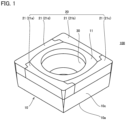
- Fig. 1 is a perspective view of cutting insert 100. As shown in Fig. 1 , cutting insert 100 includes a substrate 10 and a cutting-edge insert 20.
- Substrate 10 is made of, for example, cemented carbide. Alternatively, substrate 10 may be made of a material other than cemented carbide.
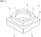
- Fig. 2 is a perspective view of substrate 10.
- Fig. 3 is a plan view of substrate 10. As shown in Figs. 2 and 3 , substrate 10 has a bottom surface 10a and a top surface 10b in a thickness direction of substrate 10. Top surface 10b is opposite to bottom surface 10a.
- Substrate 10 further has a side surface 10c. Side surface 10c is contiguous to bottom surface 10a and top surface 10b.
- Top surface 10b has a polygonal shape in a plan view as seen along the thickness direction of substrate 10 (hereinafter, merely referred to as "plan view").
- the polygonal shape may not be a mathematically rigorous polygonal shape.
- substrate 10 has a polygonal shape in plan view even when top surface 10b has rounded corners.
- top surface 10b has a quadrangular shape (square shape).
- top surface 10b is composed of a first side 10ba, a second side 10bb, a third side 10bc, and a fourth side 10bd.
- First side 10ba is contiguous to third side 10bc at one end and is contiguous to fourth side 10bd at the other end.
- Second side 10bb is contiguous to fourth side 10bd at one end and is contiguous to third side 10bc at the other end.
- Top surface 10b is provided with a projection 11.
- Projection 11 projects to the side opposite to bottom surface 10a in the thickness direction of substrate 10. In other words, there is a difference in level between projection 11 and top surface 10b. Projection 11 is located at the center of top surface 10b in plan view.
- Projection 11 has a top surface 11a and a side surface 11b.
- Top surface 11a is parallel to, for example, top surface 10b (bottom surface 10a).
- Side surface 11b is contiguous to top surface 11a and top surface 10b.
- Projection 11 top surface 11a
- Through-hole 30 passes through substrate 10 (cutting insert 100) along the thickness direction of substrate 10.
- Through-hole 30 is located at the center of projection 11 (at the center of top surface 11a) in plan view.
- Through-hole 30 has a circular shape in plan view.
- the center of through-hole 30 in plan view is referred to as a center C.
- a clamping screw passes through through-hole 30. As the clamping screw is fitted to a holder (not shown), cutting insert 100 is engaged with the holder to be fixed.
- side surface 116 is composed of a curved line protruding to the side opposite to through-hole 30. More specifically, side surface 11b includes a first surface 11ba, a second surface 11bb, a third surface 11bc, and a fourth surface 11bd. First surface 11ba to fourth surface 11bd face first side 10ba to fourth side 10bd, respectively.
- each of first surface 11ba to fourth surface 11bd is composed of a partial arc.
- side surface 11b is composed of an equal number of partial arcs to the number of sides of top surface 10b.
- the partial arcs have a radius of curvature larger than the radius of a circle indicating through-hole 30 in plan view.
- the curved line indicating side surface 11b has a plurality of vertices at positions at which the curved line has a minimum distance from the sides of top surface 10b, respectively.
- the vertex of the partial arc indicating first surface 11ba is referred to as a vertex P1
- the vertex of the partial arc indicating second surface 11bb is referred to as a vertex P2
- the vertex of the partial arc indicating third surface 11bc is referred to as a vertex P3
- the vertex of the partial arc indicating fourth surface 11bd is referred to as a vertex P4.
- the distance between a corner of projection 11 and center C in plan view is referred to as a distance DIS1.
- the distance between vertex P1 (vertex P2, vertex P3, vertex P4) and center C in plan view is referred to as a distance DIS2.
- Distance DIS1 is, for example, larger than distance DIS2.
- Cutting-edge insert 20 is made of, for example, a cubic boron nitride sintered material.
- the cubic boron nitride sintered material is a sintered material including cubic boron nitride particles and a binder such as cobalt.
- Cutting-edge insert 20 may be made of a polycrystalline diamond sintered material.
- the polycrystalline diamond sintered material is a sintered material including diamond particles and a binder such as cobalt.
- Cutting-edge insert 20 may be made of a material higher in hardness than substrate 10 other than the cubic boron nitride sintered material and the polycrystalline diamond sintered material.
- Cutting-edge insert 20 is divided into a plurality of divided pieces 21 in plan view.
- the number of divided pieces 21 is four.
- cutting-edge insert 20 is divided into an equal number of divided pieces 21 to the number of sides of top surface 10b.
- Divided pieces 21 have, for example, the same shape.
- the respective four divided pieces may be referred to as a divided piece 21a, a divided piece 21b, a divided piece 21c, and a divided piece 21d below.
- cutting-edge insert 20 is arranged on top surface 10b so as to annularly surround projection 11. More specifically, cutting-edge insert 20 is arranged on top surface 10b such that the longitudinal direction of divided piece 21a extends along first side 10ba, the longitudinal direction of divided piece 21b extends along second side 10bb, the longitudinal direction of divided piece 21c extends along third side 10bc, and the longitudinal direction of divided piece 21d extends along fourth side 10bd (see Fig. 5 ).
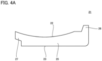
- Fig. 4A is a plan view of divided piece 21.
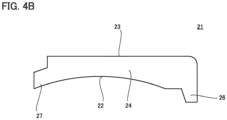
- Fig. 4B is a bottom view of divided piece 21.
- Each divided piece 21 has a side surface 22, a side surface 23, a bottom surface 24, and a top surface 25, as shown in Figs. 4A and 4B .
- Each divided piece further has a first protrusion 26 and a second protrusion 27.
- Side surface 22 faces side surface 11b (first surface 11ba to fourth surface 11bd) with cutting-edge insert 20 being attached to substrate 10.
- Side surface 22 has a shape extending along side surface 11b (first surface 11ba to fourth surface 11bd).
- Side surface 23 is opposite to side surface 22 and is contiguous to side surface 10c with cutting-edge insert 20 being attached to substrate 10.
- Side surface 23 is a flank face of cutting insert 100.
- Bottom surface 24 is opposite to top surface 10b with cutting-edge insert 20 being attached to substrate 10.
- Top surface 25 is opposite to bottom surface 24.
- top surface 25 is flush with top surface 11a with cutting-edge insert 20 being attached to substrate 10.
- Top surface 25 is a rake face of cutting insert 100.
- the ridgeline between side surface 23 and top surface 25 is a cutting edge of cutting insert 100.
- First protrusion 26 is located at one end of divided piece 21 in the longitudinal direction
- second protrusion 27 is located at the other end of divided piece 21 in the longitudinal direction.
- First protrusion 26 protrudes from the one end of divided piece 21 in the longitudinal direction along the direction crossing the longitudinal direction of divided piece 21.
- Second protrusion 27 protrudes from the other end of divided piece 21 in the longitudinal direction along the longitudinal direction of divided piece 21.
- Fig. 5 is a plan view of cutting insert 100. As shown in Fig. 5 , first protrusion 26 of divided piece 21a retains second protrusion 27 of divided piece 21c between third surface 11bc and first protrusion 26 of divided piece 21a. First protrusion 26 of divided piece 21b retains second protrusion 27 of divided piece 21d between fourth surface 11bd and first protrusion 26 of divided piece 21b.
- First protrusion 26 of divided piece 21c retains second protrusion 27 of divided piece 21b between second surface 11bb and first protrusion 26 of divided piece 21c.
- First protrusion 26 of divided piece 21d retains second protrusion 27 of divided piece 21a between first surface 11ba and first protrusion 26 of divided piece 21d.
- first protrusion 26 of one divided piece 21 retains second protrusion 27 of another divided piece 21, which is adjacent to the one divided piece 21, between side surface 11b and first protrusion 26 of the one divided piece 21.
- the positions of the centers of gravity of divided piece 21a to divided piece 21d are referred to as a position of the center of gravity P5 to a position of the center of gravity P8, respectively.
- position of the center of gravity P5 is displaced from vertex P1 toward the one end of divided piece 21a in the longitudinal direction of divided piece 21a
- position of the center of gravity P6 is displaced from vertex P2 toward the one end of divided piece 21b in the longitudinal direction of divided piece 21b.
- position of the center of gravity P7 is displaced from vertex P3 toward the one end of divided piece 21c in the longitudinal direction of divided piece 21c
- position of the center of gravity P8 is displaced from vertex P4 toward the one end of divided piece 21d in the longitudinal direction of divided piece 21d.
- the positions of the centers of gravity of divided pieces 21 are displaced from the vertices of the curved lines indicating side surface 11b, respectively, in the longitudinal direction of divided piece 21.
- Cutting-edge insert 20 is brazed to substrate 10. More specifically, side surface 22 is jointed to side surface 11b, and bottom surface 24 is joined to top surface 10b. Thus, cutting-edge insert 20 is attached to substrate 10.
- a method of manufacturing cutting insert 100 will be described below.
- Fig. 6 is a flowchart showing the method of manufacturing cutting insert 100.
- the method of manufacturing cutting insert 100 includes a preparation step S1 and a brazing step S2, as shown in Fig. ⁇ .
- preparation step S1 substrate 10 and cutting-edge insert 20 (divided pieces 21) are prepared.
- brazing step S2 cutting-edge insert 20 is brazed to substrate 10. More specifically, first, a brazing material is applied onto top surface 10b and side surface 11b. Second, each of divided pieces 21 is placed on substrate 10 such that bottom surface 24 and side surface 22 face top surface 10b and side surface 11b, respectively, with the brazing material in between. Third, substrate 10 on which divided pieces 21 are placed is put into a heating furnace. As a result, the brazing material melts, and divided pieces 21 are joined to substrate 10.
- cutting insert 100 The effects of cutting insert 100 will be described below by comparison with a cutting insert (hereinafter referred to as "cutting insert 100A") according to a first comparative example and a cutting insert (hereinafter referred to as “cutting insert 100B") according to a second comparative example.
- cutting insert 100A a cutting insert according to a first comparative example
- cutting insert 100B a cutting insert according to a second comparative example
- Fig. 7 is an exploded perspective view of cutting insert 100A.
- cutting insert 100A includes substrate 10 and cutting-edge insert 20.
- substrate 10 has no projection 11.
- cutting-edge insert 20 is not divided into divided pieces 21 and is attached to the entire top surface 10b by brazing. In these respects, the structure of cutting insert 100A is different from the structure of cutting insert 100.
- cutting insert 100A since cutting-edge insert 20 is not divided into divided pieces 21, no gap is formed between divided pieces 21 due to a surface tension of the melted brazing material in brazing of cutting-edge insert 20 to substrate 10.
- cutting-edge insert 20 is attached to the entire top surface 10b, an increasing amount of raw material is used for cutting-edge insert 20, thus increasing the cost for manufacturing the cutting insert. This is more conspicuous when a relatively costly raw material, such as a cubic boron nitride sintered material or a polycrystalline diamond sintered material, is used for cutting-edge insert 20.
- cutting insert 100A not only substrate 10 but also cutting-edge insert 20 needs to be bored to form through-hole 30. An increasing amount of time and an increasing processing cost are required for this boring, thus reducing the productivity of cutting insert 100A.
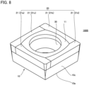
- Fig. 8 is a perspective view of cutting insert 100B.
- cutting insert 100B includes substrate 10 and cutting-edge insert 20.
- Substrate 10 of cutting insert 100B is similar to substrate 10 of cutting insert 100.
- Cutting-edge insert 20 of cutting insert 1 00B is similar to cutting-edge insert 20 of cutting insert 100 in that cutting-edge insert 20 is divided into divided pieces 21.
- each divided piece 21 has no first protrusion 26 nor second protrusion 27.
- the structure of cutting insert 100B is different from the structure of cutting insert 100.
- cutting-edge insert 20 is arranged to annularly surround projection 11, substrate 10 has no projection 11. Accordingly, the amount of a raw material used for cutting-edge insert 20 is reduced more than when cutting-edge insert 20 needs to be attached to the entire top surface 10b.
- cutting insert 100B In cutting insert 100B, cutting-edge insert 20 does not need to be bored to form through-hole 30. Thus, cutting insert 100B can be manufactured at a lower cost than cutting insert 100A.
- cutting-edge insert 20 is divided into divided pieces 21, a gap may be formed between divided pieces 21 due to a surface tension of the melted brazing material in brazing of cutting-edge insert 20 to substrate 10.
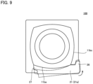
- Fig. 9 is a schematic view for describing effects of cutting insert 100.
- first surface 11ba projects to the side opposite to through-hole 30. Accordingly, as the brazing material melts, divided piece 21a attempts to rotate along first surface 11ba due to a surface tension of the melted brazing material.
- divided piece 21a since position of the center of gravity P5 is displaced from vertex P1 toward one end of divided piece 21a in the longitudinal direction of divided piece 21a, divided piece 21a tends to rotate due to a surface tension of the melted brazing material such that first protrusion 26 is closer to third surface 11bc and second protrusion 27 is farther from first surface 11ba (i.e., divided piece 21a tends to rotate counterclockwise in Fig. 9 ). Similarly, divided piece 21b to divided piece 21d also tend to rotate in the same direction as that of divided piece 21a.
- first protrusion 26 of divided piece 21a retains second protrusion 27 of divided piece 21c between third surface 11bc and first protrusion 26 of divided piece 21a
- first protrusion 26 of divided piece 21b retains second protrusion 27 of divided piece 21d between fourth surface 11bd and first protrusion 26 of divided piece 21b
- first protrusion 26 of divided piece 21c retains second protrusion 27 of divided piece 21b between second surface 11bb and first protrusion 26 of divided piece 21c
- first protrusion 26 of divided piece 21d retains second protrusion 27 of divided piece 21a between first surface 11ba and first protrusion 26 of divided piece 21d.
- divided pieces 21 rotate in the same direction due to the surface tension of the melted brazing material, so that the rotations of divided pieces 21 are mutually suppressed. This suppresses the generation of a gap generated between divided pieces 21.
- cutting insert 100 also, the amount of the raw material used for cutting-edge insert 20 can be reduced, and the processing cost for forming through-hole 30 can be reduced, as in cutting insert 100B.
- cutting insert 100 further, since the ridgeline between side surface 23 located at first protrusion 26 and top surface 25 located at first protrusion 26 can be used as a cutting edge, more portions of cutting-edge insert 20 can be used as cutting edges than in cutting insert 100B.
- the width of divided piece 21 can be reduced when distance DIS1 is larger than distance DIS2.
- the amount of the raw material used for cutting-edge insert 20 can be reduced further.
- 100, 100A, 100B cutting insert 10 substrate; 10a bottom surface; 10b top surface; 10ba first side; 10bb second side; 10bc third side; 10bd fourth side; 10c side surface; 11 projection; 11a top surface; 11b side surface; 11ba first surface; 11bb second surface; 11be third surface; 11bd fourth surface; 20 cutting-edge insert; 21, 21a, 21b, 21c, 21d divided piece; 22, 23 side surface; 24 bottom surface; 25 top surface; 26 first protrusion; 27 second protrusion; 30 through-hole; C center; DISI, DIS2 distance; P1, P2, P3, P4 vertex; P5, P6, P7, P8 position of the center of gravity; S1 preparation step; S2 brazing step.
Landscapes
- Engineering & Computer Science (AREA)
- Mechanical Engineering (AREA)
- Cutting Tools, Boring Holders, And Turrets (AREA)
Abstract
Description
- The present disclosure relates to a cutting insert and a method of manufacturing the cutting insert.
- PTL 1 (
Japanese Utility Model Laying-Open No. 60-53404 - PTL 1:
Japanese Utility Model Laying-Open No. 60-53404 - A cutting insert according to the present disclosure includes a substrate and a cutting-edge insert. The substrate has, in a thickness direction of the substrate, a bottom surface, and a top surface opposite to the bottom surface. The top surface has a polygonal shape composed of a plurality of sides in a plan view as seen along the thickness direction. The top surface is provided with a projection projecting to a side opposite to the bottom surface along the thickness direction. The projection has a through-hole passing through the substrate along the thickness direction. The projection has a side surface contiguous to the top surface. The side surface is composed of a curved line protruding to a side opposite to the through-hole in the plan view as seen along the thickness direction. The curved line includes a plurality of vertices at positions at which the curved line has a minimum distance from the plurality of sides, respectively. The cutting-edge insert is brazed to the top surface and the side surface so as to annularly surround the projection. The cutting-edge insert includes a plurality of divided pieces. A number of the plurality of divided pieces is equal to a number of the plurality of sides. The plurality of divided pieces in a longitudinal direction extend along the plurality of sides, respectively. Each of the plurality of divided pieces has, in the longitudinal direction, a first end, and a second end opposite to the first end. Each of the plurality of divided pieces has a first protrusion at the first end, and a second protrusion at the second end. The first protrusion of one divided piece among the plurality of divided pieces retains the second protrusion of another divided piece among the plurality of divided pieces between the side surface and the first protrusion of the one divided piece, the other divided piece being adjacent to the one divided piece. Positions of centers of gravity of the plurality of divided pieces are displaced from the plurality of vertices, respectively, in the longitudinal direction.
-
-
Fig. 1 is a perspective view of a cutting insert 100. -
Fig. 2 is a perspective view of asubstrate 10. -
Fig. 3 is a plan view ofsubstrate 10. -
Fig. 4A is a plan view of a dividedpiece 21. -
Fig. 4B is a bottom view of dividedpiece 21. -
Fig. 5 is a plan view ofcutting insert 100. -
Fig. 6 is a flowchart showing a method of manufacturingcutting insert 100. -
Fig. 7 is an exploded perspective view of a cutting insert 1 00A. -
Fig. 8 is a perspective view of acutting insert 100B. -
Fig. 9 is a schematic view for describing effects ofcutting insert 100. - In the cutting tool disclosed in PTL 1, in brazing of the plurality of hard sintered material pieces to the core, the respective positions of the plurality of hard sintered material pieces may be displaced due to a surface tension of a brazing material. This may cause a gap between the plurality of hard sintered material pieces.
- The present disclosure has been made in view of the above-mentioned problem with the conventional technology. More specifically, the present disclosure provides a cutting insert that can suppress the generation of a gap between a plurality of divided pieces of a cutting-edge insert, and also provides a method of manufacturing the cutting insert.
- The cutting insert according to the present disclosure can suppress the generation of a gap between the plurality of divided pieces of the cutting-edge insert.
- First, embodiments of the present disclosure will be listed and described.
- (1) A cutting insert according to an embodiment includes a substrate and a cutting-edge insert. The substrate has, in a thickness direction of the substrate, a bottom surface, and a top surface opposite to the bottom surface. The top surface has a polygonal shape composed of a plurality of sides in a plan view as seen along the thickness direction. The top surface is provided with a projection projecting to a side opposite to the bottom surface along the thickness direction. The projection has a through-hole passing through the substrate along the thickness direction. The projection has a side surface contiguous to the top surface. The side surface is composed of a curved line protruding to a side opposite to the through-hole in the plan view as seen along the thickness direction. The curved line includes a plurality of vertices at positions at which the curved line has a minimum distance from the plurality of sides, respectively. The cutting-edge insert is brazed to the top surface and the side surface so as to annularly surround the projection. The cutting-edge insert includes a plurality of divided pieces. A number of the plurality of divided pieces is equal to a number of the plurality of sides. The plurality of divided pieces in a longitudinal direction extend along the plurality of sides, respectively. Each of the plurality of divided pieces has, in the longitudinal direction, a first end, and a second end opposite to the first end. Each of the plurality of divided pieces has a first protrusion at the first end, and a second protrusion at the second end. The first protrusion of one divided piece among the plurality of divided pieces retains the second protrusion of another divided piece among the plurality of divided pieces between the side surface and the first protrusion of the one divided piece, the other divided piece being adjacent to the one divided piece. Positions of centers of gravity of the plurality of divided pieces are displaced from the plurality of vertices, respectively, in the longitudinal direction.
- The cutting insert according to (1) above can suppress the generation of a gap between the plurality of divided pieces of the cutting-edge insert. The cutting insert according to (1) above can also reduce the amount of a raw material used for the cutting-edge insert and the cost for processing the cutting-edge insert. Further, the cutting insert according to (1) above can use more portions of the cutting-edge insert as cutting edges.
- (2) In the cutting insert according to (1) above, the curved line may be composed of a plurality of partial arcs. The plurality of partial arcs may face the plurality of sides, respectively. In the plan view as seen along the thickness direction, a distance between a comer of the projection and a center of the through-hole may be larger than a distance between each of the plurality of vertices and the center. In this case, the amount of a raw material used for the cutting-edge insert can be reduced further.
- (3) In the cutting insert according to (1) or (2) above, the cutting-edge insert may be made of a cubic boron nitride sintered material or a polycrystalline diamond sintered material.
- (4) A method of manufacturing a cutting insert according to an embodiment includes preparing a substrate and a cutting-edge insert, and brazing the cutting-edge insert to the substrate. The substrate has, in a thickness direction of the substrate, a bottom surface, and a top surface opposite to the bottom surface. The top surface has a polygonal shape composed of a plurality of sides in a plan view as seen along the thickness direction. The top surface is provided with a projection projecting to a side opposite to the bottom surface along the thickness direction. The projection has a through-hole passing through the substrate along the thickness direction. The projection has a side surface contiguous to the top surface. The side surface is composed of a curved line protruding to a side opposite to the through-hole in the plan view as seen along the thickness direction. The curved line includes a plurality of vertices at positions at which the curved line has a minimum distance from the plurality of sides, respectively. The cutting-edge insert is brazed to the top surface and the side surface so as to annularly surround the projection. The cutting-edge insert includes a plurality of divided pieces. A number of the plurality of divided pieces is equal to a number of the plurality of sides. The plurality of divided pieces in a longitudinal direction extend along the plurality of sides, respectively. Each of the plurality of divided pieces has, in the longitudinal direction, a first end, and a second end opposite to the first end. Each of the plurality of divided pieces has a first protrusion at the first end, and a second protrusion at the second end. The first protrusion of one divided piece among the plurality of divided pieces retains the second protrusion of another divided piece among the plurality of divided pieces between the side surface and the first protrusion of the one divided piece, the other divided piece being adjacent to the one divided piece. Positions of centers of gravity of the plurality of divided pieces are displaced from the plurality of vertices, respectively, in the longitudinal direction.
- The method of manufacturing a cutting insert according to (4) above can suppress the generation of a gap between the plurality of divided pieces of the cutting-edge insert. The method of manufacturing a cutting insert according to (4) above can also reduce the amount of a raw material required for the cutting-edge insert and the cost for processing the cutting-edge insert. Further, the method of manufacturing a cutting insert according to (4) above can use more portions of the cutting-edge insert as cutting edges.
- Next, details of embodiments of the present disclosure will be described with reference to the drawings. The same or corresponding parts in the drawings have the same reference characters allotted, and redundant description will not be repeated.
- The structure of a cutting insert (hereinafter referred to as "cutting
insert 100") according to an embodiment will be described below. -
Fig. 1 is a perspective view of cuttinginsert 100. As shown inFig. 1 , cuttinginsert 100 includes asubstrate 10 and a cutting-edge insert 20. -
Substrate 10 is made of, for example, cemented carbide. Alternatively,substrate 10 may be made of a material other than cemented carbide.Fig. 2 is a perspective view ofsubstrate 10.Fig. 3 is a plan view ofsubstrate 10. As shown inFigs. 2 and3 ,substrate 10 has abottom surface 10a and atop surface 10b in a thickness direction ofsubstrate 10.Top surface 10b is opposite tobottom surface 10a.Substrate 10 further has aside surface 10c.Side surface 10c is contiguous tobottom surface 10a andtop surface 10b. -
Top surface 10b has a polygonal shape in a plan view as seen along the thickness direction of substrate 10 (hereinafter, merely referred to as "plan view"). The polygonal shape may not be a mathematically rigorous polygonal shape. For example,substrate 10 has a polygonal shape in plan view even whentop surface 10b has rounded corners. In the example ofFig. 3 ,top surface 10b has a quadrangular shape (square shape). - The above-mentioned polygonal shape (
top surface 10b) is composed of a first side 10ba, a second side 10bb, a third side 10bc, and a fourth side 10bd. First side 10ba is contiguous to third side 10bc at one end and is contiguous to fourth side 10bd at the other end. Second side 10bb is contiguous to fourth side 10bd at one end and is contiguous to third side 10bc at the other end. -
Top surface 10b is provided with aprojection 11.Projection 11 projects to the side opposite tobottom surface 10a in the thickness direction ofsubstrate 10. In other words, there is a difference in level betweenprojection 11 andtop surface 10b.Projection 11 is located at the center oftop surface 10b in plan view. -
Projection 11 has atop surface 11a and aside surface 11b.Top surface 11a is parallel to, for example,top surface 10b (bottom surface 10a).Side surface 11b is contiguous totop surface 11a andtop surface 10b. - Projection 11 (
top surface 11a) has a through-hole 30. Through-hole 30 passes through substrate 10 (cutting insert 100) along the thickness direction ofsubstrate 10. Through-hole 30 is located at the center of projection 11 (at the center oftop surface 11a) in plan view. Through-hole 30 has a circular shape in plan view. The center of through-hole 30 in plan view is referred to as a center C. - Though not shown, a clamping screw passes through through-
hole 30. As the clamping screw is fitted to a holder (not shown), cuttinginsert 100 is engaged with the holder to be fixed. - In plan view, side surface 116 is composed of a curved line protruding to the side opposite to through-
hole 30. More specifically,side surface 11b includes a first surface 11ba, a second surface 11bb, a third surface 11bc, and a fourth surface 11bd. First surface 11ba to fourth surface 11bd face first side 10ba to fourth side 10bd, respectively. - In a plan view orthogonal to
top surface 10b, each of first surface 11ba to fourth surface 11bd is composed of a partial arc. In other words, in plan view,side surface 11b is composed of an equal number of partial arcs to the number of sides oftop surface 10b. The partial arcs have a radius of curvature larger than the radius of a circle indicating through-hole 30 in plan view. - In plan view, the curved line indicating
side surface 11b has a plurality of vertices at positions at which the curved line has a minimum distance from the sides oftop surface 10b, respectively. Among the vertices, the vertex of the partial arc indicating first surface 11ba is referred to as a vertex P1, the vertex of the partial arc indicating second surface 11bb is referred to as a vertex P2, the vertex of the partial arc indicating third surface 11bc is referred to as a vertex P3, and the vertex of the partial arc indicating fourth surface 11bd is referred to as a vertex P4. - The distance between a corner of
projection 11 and center C in plan view is referred to as a distance DIS1. The distance between vertex P1 (vertex P2, vertex P3, vertex P4) and center C in plan view is referred to as a distance DIS2. Distance DIS1 is, for example, larger than distance DIS2. - Cutting-
edge insert 20 is made of, for example, a cubic boron nitride sintered material. The cubic boron nitride sintered material is a sintered material including cubic boron nitride particles and a binder such as cobalt. Cutting-edge insert 20 may be made of a polycrystalline diamond sintered material. The polycrystalline diamond sintered material is a sintered material including diamond particles and a binder such as cobalt. Cutting-edge insert 20 may be made of a material higher in hardness thansubstrate 10 other than the cubic boron nitride sintered material and the polycrystalline diamond sintered material. - Cutting-
edge insert 20 is divided into a plurality of dividedpieces 21 in plan view. The number of dividedpieces 21 is four. Specifically, cutting-edge insert 20 is divided into an equal number of dividedpieces 21 to the number of sides oftop surface 10b. Dividedpieces 21 have, for example, the same shape. The respective four divided pieces may be referred to as a dividedpiece 21a, a dividedpiece 21b, a dividedpiece 21c, and a dividedpiece 21d below. - As shown in
Fig. 1 , cutting-edge insert 20 is arranged ontop surface 10b so as to annularlysurround projection 11. More specifically, cutting-edge insert 20 is arranged ontop surface 10b such that the longitudinal direction of dividedpiece 21a extends along first side 10ba, the longitudinal direction of dividedpiece 21b extends along second side 10bb, the longitudinal direction of dividedpiece 21c extends along third side 10bc, and the longitudinal direction of dividedpiece 21d extends along fourth side 10bd (seeFig. 5 ). -
Fig. 4A is a plan view of dividedpiece 21.Fig. 4B is a bottom view of dividedpiece 21. Each dividedpiece 21 has aside surface 22, aside surface 23, abottom surface 24, and atop surface 25, as shown inFigs. 4A and4B . Each divided piece further has afirst protrusion 26 and asecond protrusion 27. -
Side surface 22 facesside surface 11b (first surface 11ba to fourth surface 11bd) with cutting-edge insert 20 being attached tosubstrate 10.Side surface 22 has a shape extending alongside surface 11b (first surface 11ba to fourth surface 11bd).Side surface 23 is opposite to sidesurface 22 and is contiguous toside surface 10c with cutting-edge insert 20 being attached tosubstrate 10.Side surface 23 is a flank face of cuttinginsert 100. -
Bottom surface 24 is opposite totop surface 10b with cutting-edge insert 20 being attached tosubstrate 10.Top surface 25 is opposite tobottom surface 24. For example,top surface 25 is flush withtop surface 11a with cutting-edge insert 20 being attached tosubstrate 10.Top surface 25 is a rake face of cuttinginsert 100. The ridgeline betweenside surface 23 andtop surface 25 is a cutting edge of cuttinginsert 100. -
First protrusion 26 is located at one end of dividedpiece 21 in the longitudinal direction, andsecond protrusion 27 is located at the other end of dividedpiece 21 in the longitudinal direction.First protrusion 26 protrudes from the one end of dividedpiece 21 in the longitudinal direction along the direction crossing the longitudinal direction of dividedpiece 21.Second protrusion 27 protrudes from the other end of dividedpiece 21 in the longitudinal direction along the longitudinal direction of dividedpiece 21. -
Fig. 5 is a plan view of cuttinginsert 100. As shown inFig. 5 ,first protrusion 26 of dividedpiece 21a retainssecond protrusion 27 of dividedpiece 21c between third surface 11bc andfirst protrusion 26 of dividedpiece 21a.First protrusion 26 of dividedpiece 21b retainssecond protrusion 27 of dividedpiece 21d between fourth surface 11bd andfirst protrusion 26 of dividedpiece 21b. -
First protrusion 26 of dividedpiece 21c retainssecond protrusion 27 of dividedpiece 21b between second surface 11bb andfirst protrusion 26 of dividedpiece 21c.First protrusion 26 of dividedpiece 21d retainssecond protrusion 27 of dividedpiece 21a between first surface 11ba andfirst protrusion 26 of dividedpiece 21d. Specifically, with cutting-edge insert 20 being attached tosubstrate 10,first protrusion 26 of one dividedpiece 21 retainssecond protrusion 27 of another dividedpiece 21, which is adjacent to the one dividedpiece 21, betweenside surface 11b andfirst protrusion 26 of the one dividedpiece 21. - The positions of the centers of gravity of divided
piece 21a to dividedpiece 21d are referred to as a position of the center of gravity P5 to a position of the center of gravity P8, respectively. With cutting-edge insert 20 being attached tosubstrate 10, position of the center of gravity P5 is displaced from vertex P1 toward the one end of dividedpiece 21a in the longitudinal direction of dividedpiece 21a, and position of the center of gravity P6 is displaced from vertex P2 toward the one end of dividedpiece 21b in the longitudinal direction of dividedpiece 21b. - With cutting-
edge insert 20 being attached tosubstrate 10, position of the center of gravity P7 is displaced from vertex P3 toward the one end of dividedpiece 21c in the longitudinal direction of dividedpiece 21c, and position of the center of gravity P8 is displaced from vertex P4 toward the one end of dividedpiece 21d in the longitudinal direction of dividedpiece 21d. In other words, the positions of the centers of gravity of dividedpieces 21 are displaced from the vertices of the curved lines indicatingside surface 11b, respectively, in the longitudinal direction of dividedpiece 21. - Cutting-
edge insert 20 is brazed tosubstrate 10. More specifically,side surface 22 is jointed toside surface 11b, andbottom surface 24 is joined totop surface 10b. Thus, cutting-edge insert 20 is attached tosubstrate 10. - A method of manufacturing cutting
insert 100 will be described below. -
Fig. 6 is a flowchart showing the method of manufacturing cuttinginsert 100. The method of manufacturing cuttinginsert 100 includes a preparation step S1 and a brazing step S2, as shown in Fig. δ. In preparation step S1,substrate 10 and cutting-edge insert 20 (divided pieces 21) are prepared. - In brazing step S2, cutting-
edge insert 20 is brazed tosubstrate 10. More specifically, first, a brazing material is applied ontotop surface 10b andside surface 11b. Second, each of dividedpieces 21 is placed onsubstrate 10 such thatbottom surface 24 and side surface 22 facetop surface 10b andside surface 11b, respectively, with the brazing material in between. Third,substrate 10 on which dividedpieces 21 are placed is put into a heating furnace. As a result, the brazing material melts, and dividedpieces 21 are joined tosubstrate 10. - The effects of cutting
insert 100 will be described below by comparison with a cutting insert (hereinafter referred to as "cuttinginsert 100A") according to a first comparative example and a cutting insert (hereinafter referred to as "cuttinginsert 100B") according to a second comparative example. -
Fig. 7 is an exploded perspective view of cuttinginsert 100A. As shown inFig. 7 , cuttinginsert 100A includessubstrate 10 and cutting-edge insert 20. In cuttinginsert 100A,substrate 10 has noprojection 11. Also, in cuttinginsert 100A, cutting-edge insert 20 is not divided into dividedpieces 21 and is attached to the entiretop surface 10b by brazing. In these respects, the structure of cuttinginsert 100A is different from the structure of cuttinginsert 100. - In cutting
insert 100A, since cutting-edge insert 20 is not divided into dividedpieces 21, no gap is formed between dividedpieces 21 due to a surface tension of the melted brazing material in brazing of cutting-edge insert 20 tosubstrate 10. - In cutting
insert 100A, however, since cutting-edge insert 20 is attached to the entiretop surface 10b, an increasing amount of raw material is used for cutting-edge insert 20, thus increasing the cost for manufacturing the cutting insert. This is more conspicuous when a relatively costly raw material, such as a cubic boron nitride sintered material or a polycrystalline diamond sintered material, is used for cutting-edge insert 20. - In cutting
insert 100A, not onlysubstrate 10 but also cutting-edge insert 20 needs to be bored to form through-hole 30. An increasing amount of time and an increasing processing cost are required for this boring, thus reducing the productivity of cuttinginsert 100A. -
Fig. 8 is a perspective view of cuttinginsert 100B. As shown inFig. 8 , cuttinginsert 100B includessubstrate 10 and cutting-edge insert 20.Substrate 10 of cuttinginsert 100B is similar tosubstrate 10 of cuttinginsert 100. Cutting-edge insert 20 of cutting insert 1 00B is similar to cutting-edge insert 20 of cuttinginsert 100 in that cutting-edge insert 20 is divided into dividedpieces 21. - In cutting
insert 100B, however, each dividedpiece 21 has nofirst protrusion 26 norsecond protrusion 27. In this respect, the structure of cuttinginsert 100B is different from the structure of cuttinginsert 100. - In cutting
insert 100B, since cutting-edge insert 20 is arranged toannularly surround projection 11,substrate 10 has noprojection 11. Accordingly, the amount of a raw material used for cutting-edge insert 20 is reduced more than when cutting-edge insert 20 needs to be attached to the entiretop surface 10b. - In cutting
insert 100B, cutting-edge insert 20 does not need to be bored to form through-hole 30. Thus, cuttinginsert 100B can be manufactured at a lower cost than cuttinginsert 100A. - In cutting
insert 100B, however, since cutting-edge insert 20 is divided into dividedpieces 21, a gap may be formed between dividedpieces 21 due to a surface tension of the melted brazing material in brazing of cutting-edge insert 20 tosubstrate 10. -
Fig. 9 is a schematic view for describing effects of cuttinginsert 100. As shown inFig. 9 , in cuttinginsert 100, first surface 11ba projects to the side opposite to through-hole 30. Accordingly, as the brazing material melts, dividedpiece 21a attempts to rotate along first surface 11ba due to a surface tension of the melted brazing material. - Also, since position of the center of gravity P5 is displaced from vertex P1 toward one end of divided
piece 21a in the longitudinal direction of dividedpiece 21a, dividedpiece 21a tends to rotate due to a surface tension of the melted brazing material such thatfirst protrusion 26 is closer to third surface 11bc andsecond protrusion 27 is farther from first surface 11ba (i.e., dividedpiece 21a tends to rotate counterclockwise inFig. 9 ). Similarly, dividedpiece 21b to dividedpiece 21d also tend to rotate in the same direction as that of dividedpiece 21a. - However,
first protrusion 26 of dividedpiece 21a retainssecond protrusion 27 of dividedpiece 21c between third surface 11bc andfirst protrusion 26 of dividedpiece 21a, andfirst protrusion 26 of dividedpiece 21b retainssecond protrusion 27 of dividedpiece 21d between fourth surface 11bd andfirst protrusion 26 of dividedpiece 21b. Also,first protrusion 26 of dividedpiece 21c retainssecond protrusion 27 of dividedpiece 21b between second surface 11bb andfirst protrusion 26 of dividedpiece 21c, andfirst protrusion 26 of dividedpiece 21d retainssecond protrusion 27 of dividedpiece 21a between first surface 11ba andfirst protrusion 26 of dividedpiece 21d. - Consequently, such a rotation of divided
piece 21c thatsecond protrusion 27 attempts to be farther from third surface 11bc is suppressed by such a rotation of dividedpiece 21a thatfirst protrusion 26 attempts to be closer to third surface 11bc, and such a rotation of dividedpiece 21d thatsecond protrusion 27 attempts to be farther from fourth surface 11bd is suppressed by such a rotation of dividedpiece 21b thatfirst protrusion 26 attempts to be closer to fourth surface 11bd. - Similarly, such a rotation of divided
piece 21b thatsecond protrusion 27 attempts to be farther from second surface 11bb is suppressed by such a rotation of dividedpiece 21c thatfirst protrusion 26 attempts to be closer to second surface 11bb, and such a rotation of dividedpiece 21a thatsecond protrusion 27 attempts to be farther from first surface 11ba is suppressed by such a rotation of dividedpiece 21d thatfirst protrusion 26 attempts to be closer to first surface 11ba. - As described above, in cutting
insert 100, dividedpieces 21 rotate in the same direction due to the surface tension of the melted brazing material, so that the rotations of dividedpieces 21 are mutually suppressed. This suppresses the generation of a gap generated between dividedpieces 21. - In cutting
insert 100, also, the amount of the raw material used for cutting-edge insert 20 can be reduced, and the processing cost for forming through-hole 30 can be reduced, as in cuttinginsert 100B. In cuttinginsert 100, further, since the ridgeline betweenside surface 23 located atfirst protrusion 26 andtop surface 25 located atfirst protrusion 26 can be used as a cutting edge, more portions of cutting-edge insert 20 can be used as cutting edges than in cuttinginsert 100B. - In cutting
insert 100, the width of dividedpiece 21 can be reduced when distance DIS1 is larger than distance DIS2. Thus, the amount of the raw material used for cutting-edge insert 20 can be reduced further. - It should be understood that the embodiments disclosed herein are illustrative and non-restrictive in every respect. The scope of the present invention is defined by the terms of the claims, rather than the description above, and is intended to include any modifications within the meaning and scope equivalent to the terms of the claims.
- 100, 100A, 100B cutting insert; 10 substrate; 10a bottom surface; 10b top surface; 10ba first side; 10bb second side; 10bc third side; 10bd fourth side; 10c side surface; 11 projection; 11a top surface; 11b side surface; 11ba first surface; 11bb second surface; 11be third surface; 11bd fourth surface; 20 cutting-edge insert; 21, 21a, 21b, 21c, 21d divided piece; 22, 23 side surface; 24 bottom surface; 25 top surface; 26 first protrusion; 27 second protrusion; 30 through-hole; C center; DISI, DIS2 distance; P1, P2, P3, P4 vertex; P5, P6, P7, P8 position of the center of gravity; S1 preparation step; S2 brazing step.
Claims (4)
- A cutting insert comprising:a substrate; anda cutting-edge insert, whereinthe substrate has in a thickness direction of the substratea bottom surface, anda top surface opposite to the bottom surface,the top surface has a polygonal shape composed of a plurality of sides in a plan view as seen along the thickness direction,the top surface is provided with a projection projecting to a side opposite to the bottom surface along the thickness direction,the projection has a through-hole passing through the substrate along the thickness direction,the projection has a side surface contiguous to the top surface,the side surface is composed of a curved line protruding to a side opposite to the through-hole in the plan view as seen along the thickness direction,the curved line includes a plurality of vertices at positions at which the curved line has a minimum distance from the plurality of sides, respectively,the cutting-edge insert is brazed to the top surface and the side surface so as to annularly surround the projection,the cutting-edge insert includes a plurality of divided pieces,a number of the plurality of divided pieces is equal to a number of the plurality of sides,the plurality of divided pieces in a longitudinal direction extend along the plurality of sides, respectively,each of the plurality of divided pieces has in the longitudinal directiona first end, anda second end opposite to the first end,each of the plurality of divided pieces hasa first protrusion at the first end, anda second protrusion at the second end,the first protrusion of one divided piece among the plurality of divided pieces retains the second protrusion of another divided piece among the plurality of divided pieces between the side surface and the first protrusion of the one divided piece, the other divided piece being adjacent to the one divided piece, andpositions of centers of gravity of the plurality of divided pieces are displaced from the plurality of vertices, respectively, in the longitudinal direction.
- The cutting insert according to claim 1, whereinthe curved line is composed of a plurality of partial arcs,the plurality of partial arcs face the plurality of sides, respectively, andin the plan view as seen along the thickness direction, a distance between a corner of the projection and a center of the through-hole is larger than a distance between each of the plurality of vertices and the center.
- The cutting insert according to claim 1 or 2, wherein the cutting-edge insert is made of a cubic boron nitride sintered material or a polycrystalline diamond sintered material.
- A method of manufacturing a cutting insert, the method comprising:preparing a substrate and a cutting-edge insert; andbrazing the cutting-edge insert to the substrate, whereinthe substrate has in a thickness direction of the substratea bottom surface, anda top surface opposite to the bottom surface,the top surface has a polygonal shape composed of a plurality of sides in a plan view as seen along the thickness direction,the top surface is provided with a projection projecting to a side opposite to the bottom surface along the thickness direction,the projection has a through-hole passing through the substrate along the thickness direction,the projection has a side surface contiguous to the top surface,the side surface is composed of a curved line protruding to a side opposite to the through-hole in the plan view as seen along the thickness direction,the curved line includes a plurality of vertices at positions at which the curved line has a minimum distance from the plurality of sides, respectively,the cutting-edge insert is brazed to the top surface and the side surface so as to annularly surround the projection,the cutting-edge insert includes a plurality of divided pieces,a number of the plurality of divided pieces is equal to a number of the plurality of sides,the plurality of divided pieces in a longitudinal direction extend along the plurality of sides, respectively,each of the plurality of divided pieces has in the longitudinal directiona first end, anda second end opposite to the first end,each of the plurality of divided pieces hasa first protrusion at the first end, anda second protrusion at the second end,the first protrusion of one divided piece among the plurality of divided pieces retains the second protrusion of another divided piece among the plurality of divided pieces between the side surface and the first protrusion of the one divided piece, the other divided piece being adjacent to the one divided piece, andpositions of centers of gravity of the plurality of divided pieces arc displaced from the plurality of vertices, respectively, in the longitudinal direction.
Applications Claiming Priority (1)
| Application Number | Priority Date | Filing Date | Title |
|---|---|---|---|
| PCT/JP2020/023736 WO2021255852A1 (en) | 2020-06-17 | 2020-06-17 | Cutting insert and method for manufacturing cutting insert |
Publications (3)
| Publication Number | Publication Date |
|---|---|
| EP4169663A1 true EP4169663A1 (en) | 2023-04-26 |
| EP4169663A4 EP4169663A4 (en) | 2023-08-09 |
| EP4169663B1 EP4169663B1 (en) | 2024-06-05 |
Family
ID=79268710
Family Applications (1)
| Application Number | Title | Priority Date | Filing Date |
|---|---|---|---|
| EP20940838.4A Active EP4169663B1 (en) | 2020-06-17 | 2020-06-17 | Cutting insert and method of manufacturing cutting insert |
Country Status (5)
| Country | Link |
|---|---|
| US (1) | US12447537B2 (en) |
| EP (1) | EP4169663B1 (en) |
| JP (1) | JP7419531B2 (en) |
| CN (1) | CN115835938A (en) |
| WO (1) | WO2021255852A1 (en) |
Family Cites Families (56)
| Publication number | Priority date | Publication date | Assignee | Title |
|---|---|---|---|---|
| US2475565A (en) * | 1946-09-21 | 1949-07-05 | Carborundum Co | Ceramic bonded abrasive articles |
| SE305791B (en) * | 1964-02-06 | 1968-11-04 | Diadur Ab | |
| JPS5652604U (en) * | 1979-09-27 | 1981-05-09 | ||
| US4448591A (en) * | 1981-01-21 | 1984-05-15 | General Electric Company | Cutting insert having unique cross section |
| US4504284A (en) * | 1981-07-24 | 1985-03-12 | General Electric Company | Indexable composite cutting insert having corner cutting edges |
| US4698070A (en) * | 1981-12-16 | 1987-10-06 | General Electric Company | Cutting insert for interrupted heavy machining |
| US4561810A (en) * | 1981-12-16 | 1985-12-31 | General Electric Company | Bi-level cutting insert |
| JPS58120406A (en) * | 1982-01-14 | 1983-07-18 | Nippon Oil & Fats Co Ltd | High hardness sintered tool |
| JPS6053404U (en) * | 1983-09-19 | 1985-04-15 | 住友電気工業株式会社 | Cutting tools |
| SE445314B (en) * | 1984-09-26 | 1986-06-16 | Santrade Ltd | TOOLS WITH FENDER PREFERRED FOR SWEARING |
| EP0210576B1 (en) * | 1985-08-01 | 1989-05-31 | Techno Saarstahl GmbH | Cutting tool |
| US4854784A (en) * | 1988-10-19 | 1989-08-08 | Kennametal Inc. | Diamond tipped chip control insert |
| US5282703A (en) * | 1991-03-29 | 1994-02-01 | Mitsubishi Materials Corporation | Indexable cutter insert |
| US5193948A (en) * | 1991-12-16 | 1993-03-16 | Gte Valenite Corporation | Chip control inserts with diamond segments |
| US5405711A (en) * | 1993-09-20 | 1995-04-11 | Valenite Inc. | Indexable inserts with polycrystalline cutting edge |
| KR950031336A (en) * | 1994-02-28 | 1995-12-18 | 아키모토 유우미 | Drawaway Tips and Cutting Tools |
| JPH10118824A (en) * | 1996-10-24 | 1998-05-12 | Fuji Seiko Kk | Vertical type tip and milling cutter therewith |
| US6155755A (en) * | 1998-03-02 | 2000-12-05 | Sumitomo Electric Industries, Ltd. | Hard sintered body tool |
| JP3487195B2 (en) * | 1998-10-19 | 2004-01-13 | 三菱マテリアル株式会社 | Large indexable inserts |
| JP2000246512A (en) * | 1998-12-28 | 2000-09-12 | Ngk Spark Plug Co Ltd | Diamond coated cutting tools |
| DE19903037C2 (en) * | 1999-01-26 | 2003-12-04 | Jakob Lach Gmbh & Co Kg | Cutting tool with means for chip control |
| US20020131832A1 (en) * | 2001-03-15 | 2002-09-19 | Morsch Gary L. | Cutting insert with discrete tip and method for producing the same |
| CN100475431C (en) * | 2002-02-21 | 2009-04-08 | 六号元素(控股)公司 | tool bit |
| FR2840829B1 (en) * | 2002-06-14 | 2005-01-14 | Diager | FORCE DRILLING PLATE AND DRILLING TOOL USING THE PLATE |
| US20050076755A1 (en) * | 2003-03-11 | 2005-04-14 | Zimmerman Michael H. | Method and apparatus for machining fiber cement |
| CN100488710C (en) * | 2003-06-03 | 2009-05-20 | 山特维克知识产权股份有限公司 | Indexable cutter and methods for producing the same |
| US20050271483A1 (en) | 2004-06-02 | 2005-12-08 | Sandvik Ab | Indexable cutting inserts and methods for producing the same |
| US7765902B2 (en) * | 2005-10-06 | 2010-08-03 | Sumitomo Electric Hardmetal Corp. | Cutting tool for high-quality high-efficiency machining and cutting method using the same |
| EP1991383A4 (en) | 2006-03-06 | 2011-01-19 | Diamond Innovations Inc | INSERT OF CUTTING TOOL WITH MOLDED INSERT BODY |
| JP2008254127A (en) * | 2007-04-05 | 2008-10-23 | Mitsubishi Materials Corp | Cutting insert |
| US7510352B2 (en) * | 2007-08-03 | 2009-03-31 | Kennametal Inc. | Integral cutting insert clamping mechanism |
| US7955032B2 (en) * | 2009-01-06 | 2011-06-07 | Kennametal Inc. | Cutting insert with coolant delivery and method of making the cutting insert |
| WO2010100953A1 (en) * | 2009-03-06 | 2010-09-10 | 三菱マテリアル株式会社 | Cutting inset and tool having cutting inserts |
| US9242299B2 (en) * | 2010-01-07 | 2016-01-26 | Gkn Sinter Metals, Llc | Machining tool and method of manufacturing same |
| SE535420C2 (en) * | 2010-06-02 | 2012-07-31 | Sandvik Intellectual Property | Carbide inserts and cemented carbide material for the manufacture of such inserts |
| JP5828487B2 (en) | 2010-07-13 | 2015-12-09 | エレメント シックス リミテッド | Indexing type cutter insert, molded article for indexing type cutter insert and manufacturing method thereof |
| JP5853613B2 (en) * | 2010-11-15 | 2016-02-09 | 三菱マテリアル株式会社 | Cutting insert |
| US9199312B2 (en) * | 2011-03-07 | 2015-12-01 | Kennametal Inc. | Cutting insert with discrete cutting tip and chip control structure |
| JP5769531B2 (en) * | 2011-07-22 | 2015-08-26 | 京セラ株式会社 | Cutting tips and cutting tools |
| JP5906976B2 (en) * | 2011-10-04 | 2016-04-20 | 三菱マテリアル株式会社 | Cutting insert and cutting edge changeable cutting tool |
| US9649692B2 (en) * | 2012-04-23 | 2017-05-16 | Sumitomo Electric Hardmetal Corp. | Sintered cubic boron nitride compact tool |
| US20130343826A1 (en) * | 2012-06-25 | 2013-12-26 | Steven Webb | Cutting tool insert with powder metal insert body |
| JP2014121772A (en) | 2012-11-22 | 2014-07-03 | Mitsubishi Materials Corp | Cutting insert and cutting insert manufacturing method |
| JP2014221500A (en) * | 2013-05-13 | 2014-11-27 | 三菱マテリアル株式会社 | Cutting insert |
| WO2015110985A1 (en) * | 2014-01-22 | 2015-07-30 | Saturnino Fiori Cate Srl | Tool-holding device for a machining tool and method for locking a tool into a tool-holder |
| CN106414371B (en) * | 2014-06-27 | 2019-07-19 | 京瓷株式会社 | Cubic boron nitride sintered compact and cutting element |
| EP3195961B1 (en) * | 2014-09-16 | 2019-02-20 | Sumitomo Electric Industries, Ltd. | Cutting insert and manufacturing method therefor |
| US10486239B2 (en) * | 2015-02-24 | 2019-11-26 | Tungaloy Corporation | Cutting tool |
| JP6432556B2 (en) * | 2015-04-22 | 2018-12-05 | 株式会社タンガロイ | Cutting inserts and cutting tools |
| CN204934643U (en) * | 2015-09-22 | 2016-01-06 | 乐清市南方硬质合金有限公司 | Digital cuttings |
| JP6278137B1 (en) * | 2017-03-21 | 2018-02-14 | 株式会社タンガロイ | tool |
| JP6651136B2 (en) * | 2017-10-25 | 2020-02-19 | 株式会社タンガロイ | Cutting inserts, deposits and holders |
| JP7110347B2 (en) * | 2018-07-18 | 2022-08-01 | 京セラ株式会社 | Manufacturing method of cutting insert, cutting tool and cutting work |
| WO2020090737A1 (en) * | 2018-10-29 | 2020-05-07 | 京セラ株式会社 | Cutting insert, cutting tool, and method for manufacturing cut workpiece |
| JP7003388B1 (en) * | 2021-04-28 | 2022-01-20 | 株式会社タンガロイ | Cutting tools |
| JP2023029033A (en) | 2021-08-20 | 2023-03-03 | 河村電器産業株式会社 | Apparatus storing box body |
-
2020
- 2020-06-17 US US18/010,226 patent/US12447537B2/en active Active
- 2020-06-17 CN CN202080102096.6A patent/CN115835938A/en active Pending
- 2020-06-17 WO PCT/JP2020/023736 patent/WO2021255852A1/en not_active Ceased
- 2020-06-17 JP JP2022531164A patent/JP7419531B2/en active Active
- 2020-06-17 EP EP20940838.4A patent/EP4169663B1/en active Active
Also Published As
| Publication number | Publication date |
|---|---|
| US20230321732A1 (en) | 2023-10-12 |
| EP4169663A4 (en) | 2023-08-09 |
| CN115835938A (en) | 2023-03-21 |
| JP7419531B2 (en) | 2024-01-22 |
| US12447537B2 (en) | 2025-10-21 |
| WO2021255852A1 (en) | 2021-12-23 |
| EP4169663B1 (en) | 2024-06-05 |
| JPWO2021255852A1 (en) | 2021-12-23 |
Similar Documents
| Publication | Publication Date | Title |
|---|---|---|
| JP6241636B2 (en) | Cutting insert and cutting edge changeable cutting tool | |
| CN102361719B (en) | For the double-sided cutting insert of high speed feed milling | |
| CN1532013B (en) | Inserts and Cutters | |
| CN103619518B (en) | Indexable cutting inserts for milling | |
| JP6338204B1 (en) | Cutting insert and cutting tool | |
| US10315258B2 (en) | Cutting insert and cutting tool | |
| JP5460888B2 (en) | Cutting insert | |
| US9186732B2 (en) | Cutting insert with grooved surface defining plural support surfaces | |
| CN103608142B (en) | Cutting tip and rotary cutting tool | |
| WO1999047298B1 (en) | Modular cutting tool assembly | |
| EP3199283A1 (en) | Cutting insert and replaceable-edge rotary cutting tool | |
| JP5779830B2 (en) | Vertical cutting edge replaceable cutting insert and corner milling cutter | |
| CN101594959A (en) | Cutting insert for efficient cutting | |
| CN104708096A (en) | Cutting insert for heavy machining operations | |
| JP2016137569A (en) | Cutting insert and indexable rotary cutting tool | |
| JP4797526B2 (en) | Throwaway tip | |
| US10220448B2 (en) | Cutting insert, cutting tool, and method of manufacturing machined product | |
| WO2021193705A1 (en) | Rotating tool and method for manufacturing cut workpieces | |
| US10384275B2 (en) | Cutting tool and method for manufacturing the machined product | |
| EP4169663B1 (en) | Cutting insert and method of manufacturing cutting insert | |
| JPWO2016080486A1 (en) | Cutting insert and cutting edge exchangeable rotary cutting tool | |
| EP4101567A1 (en) | Cutting insert and cutting tool | |
| CN112355333B (en) | A kind of cutter and cutter head structure thereof | |
| JP2017164849A (en) | Cutting insert, cutting insert group, and blade-edge replaceable type cutting tool | |
| US10022810B2 (en) | Cutting tool and method for manufacturing machined product |
Legal Events
| Date | Code | Title | Description |
|---|---|---|---|
| STAA | Information on the status of an ep patent application or granted ep patent |
Free format text: STATUS: THE INTERNATIONAL PUBLICATION HAS BEEN MADE |
|
| PUAI | Public reference made under article 153(3) epc to a published international application that has entered the european phase |
Free format text: ORIGINAL CODE: 0009012 |
|
| STAA | Information on the status of an ep patent application or granted ep patent |
Free format text: STATUS: REQUEST FOR EXAMINATION WAS MADE |
|
| 17P | Request for examination filed |
Effective date: 20221214 |
|
| AK | Designated contracting states |
Kind code of ref document: A1 Designated state(s): AL AT BE BG CH CY CZ DE DK EE ES FI FR GB GR HR HU IE IS IT LI LT LU LV MC MK MT NL NO PL PT RO RS SE SI SK SM TR |
|
| REG | Reference to a national code |
Ref country code: DE Ref legal event code: R079 Free format text: PREVIOUS MAIN CLASS: B23P0015280000 Ipc: B23B0027140000 Ref document number: 602020032152 Country of ref document: DE |
|
| A4 | Supplementary search report drawn up and despatched |
Effective date: 20230706 |
|
| RIC1 | Information provided on ipc code assigned before grant |
Ipc: B23P 15/28 20060101ALI20230630BHEP Ipc: B23C 5/20 20060101ALI20230630BHEP Ipc: B23B 27/20 20060101ALI20230630BHEP Ipc: B23B 27/14 20060101AFI20230630BHEP |
|
| DAV | Request for validation of the european patent (deleted) | ||
| DAX | Request for extension of the european patent (deleted) | ||
| RIC1 | Information provided on ipc code assigned before grant |
Ipc: B23K 103/00 20060101ALI20231127BHEP Ipc: B23K 31/02 20060101ALI20231127BHEP Ipc: B23K 1/008 20060101ALI20231127BHEP Ipc: B23K 1/00 20060101ALI20231127BHEP Ipc: B23P 15/28 20060101ALI20231127BHEP Ipc: B23C 5/20 20060101ALI20231127BHEP Ipc: B23B 27/20 20060101ALI20231127BHEP Ipc: B23B 27/14 20060101AFI20231127BHEP |
|
| GRAP | Despatch of communication of intention to grant a patent |
Free format text: ORIGINAL CODE: EPIDOSNIGR1 |
|
| STAA | Information on the status of an ep patent application or granted ep patent |
Free format text: STATUS: GRANT OF PATENT IS INTENDED |
|
| INTG | Intention to grant announced |
Effective date: 20240109 |
|
| GRAS | Grant fee paid |
Free format text: ORIGINAL CODE: EPIDOSNIGR3 |
|
| GRAA | (expected) grant |
Free format text: ORIGINAL CODE: 0009210 |
|
| STAA | Information on the status of an ep patent application or granted ep patent |
Free format text: STATUS: THE PATENT HAS BEEN GRANTED |
|
| P01 | Opt-out of the competence of the unified patent court (upc) registered |
Effective date: 20240412 |
|
| AK | Designated contracting states |
Kind code of ref document: B1 Designated state(s): AL AT BE BG CH CY CZ DE DK EE ES FI FR GB GR HR HU IE IS IT LI LT LU LV MC MK MT NL NO PL PT RO RS SE SI SK SM TR |
|
| REG | Reference to a national code |
Ref country code: CH Ref legal event code: EP |
|
| REG | Reference to a national code |
Ref country code: DE Ref legal event code: R096 Ref document number: 602020032152 Country of ref document: DE |
|
| REG | Reference to a national code |
Ref country code: IE Ref legal event code: FG4D |
|
| REG | Reference to a national code |
Ref country code: SE Ref legal event code: TRGR |
|
| REG | Reference to a national code |
Ref country code: LT Ref legal event code: MG9D |
|
| PG25 | Lapsed in a contracting state [announced via postgrant information from national office to epo] |
Ref country code: BG Free format text: LAPSE BECAUSE OF FAILURE TO SUBMIT A TRANSLATION OF THE DESCRIPTION OR TO PAY THE FEE WITHIN THE PRESCRIBED TIME-LIMIT Effective date: 20240605 |
|
| REG | Reference to a national code |
Ref country code: NL Ref legal event code: MP Effective date: 20240605 |
|
| PG25 | Lapsed in a contracting state [announced via postgrant information from national office to epo] |
Ref country code: HR Free format text: LAPSE BECAUSE OF FAILURE TO SUBMIT A TRANSLATION OF THE DESCRIPTION OR TO PAY THE FEE WITHIN THE PRESCRIBED TIME-LIMIT Effective date: 20240605 Ref country code: FI Free format text: LAPSE BECAUSE OF FAILURE TO SUBMIT A TRANSLATION OF THE DESCRIPTION OR TO PAY THE FEE WITHIN THE PRESCRIBED TIME-LIMIT Effective date: 20240605 |
|
| PG25 | Lapsed in a contracting state [announced via postgrant information from national office to epo] |
Ref country code: GR Free format text: LAPSE BECAUSE OF FAILURE TO SUBMIT A TRANSLATION OF THE DESCRIPTION OR TO PAY THE FEE WITHIN THE PRESCRIBED TIME-LIMIT Effective date: 20240906 |
|
| PG25 | Lapsed in a contracting state [announced via postgrant information from national office to epo] |
Ref country code: ES Free format text: LAPSE BECAUSE OF FAILURE TO SUBMIT A TRANSLATION OF THE DESCRIPTION OR TO PAY THE FEE WITHIN THE PRESCRIBED TIME-LIMIT Effective date: 20240605 |
|
| PG25 | Lapsed in a contracting state [announced via postgrant information from national office to epo] |
Ref country code: LV Free format text: LAPSE BECAUSE OF FAILURE TO SUBMIT A TRANSLATION OF THE DESCRIPTION OR TO PAY THE FEE WITHIN THE PRESCRIBED TIME-LIMIT Effective date: 20240605 |
|
| PG25 | Lapsed in a contracting state [announced via postgrant information from national office to epo] |
Ref country code: NO Free format text: LAPSE BECAUSE OF FAILURE TO SUBMIT A TRANSLATION OF THE DESCRIPTION OR TO PAY THE FEE WITHIN THE PRESCRIBED TIME-LIMIT Effective date: 20240905 Ref country code: LV Free format text: LAPSE BECAUSE OF FAILURE TO SUBMIT A TRANSLATION OF THE DESCRIPTION OR TO PAY THE FEE WITHIN THE PRESCRIBED TIME-LIMIT Effective date: 20240605 Ref country code: HR Free format text: LAPSE BECAUSE OF FAILURE TO SUBMIT A TRANSLATION OF THE DESCRIPTION OR TO PAY THE FEE WITHIN THE PRESCRIBED TIME-LIMIT Effective date: 20240605 Ref country code: GR Free format text: LAPSE BECAUSE OF FAILURE TO SUBMIT A TRANSLATION OF THE DESCRIPTION OR TO PAY THE FEE WITHIN THE PRESCRIBED TIME-LIMIT Effective date: 20240906 Ref country code: FI Free format text: LAPSE BECAUSE OF FAILURE TO SUBMIT A TRANSLATION OF THE DESCRIPTION OR TO PAY THE FEE WITHIN THE PRESCRIBED TIME-LIMIT Effective date: 20240605 Ref country code: ES Free format text: LAPSE BECAUSE OF FAILURE TO SUBMIT A TRANSLATION OF THE DESCRIPTION OR TO PAY THE FEE WITHIN THE PRESCRIBED TIME-LIMIT Effective date: 20240605 Ref country code: BG Free format text: LAPSE BECAUSE OF FAILURE TO SUBMIT A TRANSLATION OF THE DESCRIPTION OR TO PAY THE FEE WITHIN THE PRESCRIBED TIME-LIMIT Effective date: 20240605 Ref country code: RS Free format text: LAPSE BECAUSE OF FAILURE TO SUBMIT A TRANSLATION OF THE DESCRIPTION OR TO PAY THE FEE WITHIN THE PRESCRIBED TIME-LIMIT Effective date: 20240905 |
|
| PG25 | Lapsed in a contracting state [announced via postgrant information from national office to epo] |
Ref country code: NL Free format text: LAPSE BECAUSE OF FAILURE TO SUBMIT A TRANSLATION OF THE DESCRIPTION OR TO PAY THE FEE WITHIN THE PRESCRIBED TIME-LIMIT Effective date: 20240605 |
|
| REG | Reference to a national code |
Ref country code: AT Ref legal event code: MK05 Ref document number: 1692100 Country of ref document: AT Kind code of ref document: T Effective date: 20240605 |
|
| PG25 | Lapsed in a contracting state [announced via postgrant information from national office to epo] |
Ref country code: NL Free format text: LAPSE BECAUSE OF FAILURE TO SUBMIT A TRANSLATION OF THE DESCRIPTION OR TO PAY THE FEE WITHIN THE PRESCRIBED TIME-LIMIT Effective date: 20240605 |
|
| PG25 | Lapsed in a contracting state [announced via postgrant information from national office to epo] |
Ref country code: PT Free format text: LAPSE BECAUSE OF FAILURE TO SUBMIT A TRANSLATION OF THE DESCRIPTION OR TO PAY THE FEE WITHIN THE PRESCRIBED TIME-LIMIT Effective date: 20241007 |
|
| PG25 | Lapsed in a contracting state [announced via postgrant information from national office to epo] |
Ref country code: PT Free format text: LAPSE BECAUSE OF FAILURE TO SUBMIT A TRANSLATION OF THE DESCRIPTION OR TO PAY THE FEE WITHIN THE PRESCRIBED TIME-LIMIT Effective date: 20241007 |
|
| PG25 | Lapsed in a contracting state [announced via postgrant information from national office to epo] |
Ref country code: PL Free format text: LAPSE BECAUSE OF FAILURE TO SUBMIT A TRANSLATION OF THE DESCRIPTION OR TO PAY THE FEE WITHIN THE PRESCRIBED TIME-LIMIT Effective date: 20240605 |
|
| PG25 | Lapsed in a contracting state [announced via postgrant information from national office to epo] |
Ref country code: EE Free format text: LAPSE BECAUSE OF FAILURE TO SUBMIT A TRANSLATION OF THE DESCRIPTION OR TO PAY THE FEE WITHIN THE PRESCRIBED TIME-LIMIT Effective date: 20240605 |
|
| PG25 | Lapsed in a contracting state [announced via postgrant information from national office to epo] |
Ref country code: AT Free format text: LAPSE BECAUSE OF FAILURE TO SUBMIT A TRANSLATION OF THE DESCRIPTION OR TO PAY THE FEE WITHIN THE PRESCRIBED TIME-LIMIT Effective date: 20240605 Ref country code: IS Free format text: LAPSE BECAUSE OF FAILURE TO SUBMIT A TRANSLATION OF THE DESCRIPTION OR TO PAY THE FEE WITHIN THE PRESCRIBED TIME-LIMIT Effective date: 20241005 |
|
| PG25 | Lapsed in a contracting state [announced via postgrant information from national office to epo] |
Ref country code: CZ Free format text: LAPSE BECAUSE OF FAILURE TO SUBMIT A TRANSLATION OF THE DESCRIPTION OR TO PAY THE FEE WITHIN THE PRESCRIBED TIME-LIMIT Effective date: 20240605 |
|
| PG25 | Lapsed in a contracting state [announced via postgrant information from national office to epo] |
Ref country code: RO Free format text: LAPSE BECAUSE OF FAILURE TO SUBMIT A TRANSLATION OF THE DESCRIPTION OR TO PAY THE FEE WITHIN THE PRESCRIBED TIME-LIMIT Effective date: 20240605 Ref country code: SK Free format text: LAPSE BECAUSE OF FAILURE TO SUBMIT A TRANSLATION OF THE DESCRIPTION OR TO PAY THE FEE WITHIN THE PRESCRIBED TIME-LIMIT Effective date: 20240605 |
|
| PG25 | Lapsed in a contracting state [announced via postgrant information from national office to epo] |
Ref country code: SM Free format text: LAPSE BECAUSE OF FAILURE TO SUBMIT A TRANSLATION OF THE DESCRIPTION OR TO PAY THE FEE WITHIN THE PRESCRIBED TIME-LIMIT Effective date: 20240605 |
|
| PG25 | Lapsed in a contracting state [announced via postgrant information from national office to epo] |
Ref country code: SM Free format text: LAPSE BECAUSE OF FAILURE TO SUBMIT A TRANSLATION OF THE DESCRIPTION OR TO PAY THE FEE WITHIN THE PRESCRIBED TIME-LIMIT Effective date: 20240605 Ref country code: SK Free format text: LAPSE BECAUSE OF FAILURE TO SUBMIT A TRANSLATION OF THE DESCRIPTION OR TO PAY THE FEE WITHIN THE PRESCRIBED TIME-LIMIT Effective date: 20240605 Ref country code: RO Free format text: LAPSE BECAUSE OF FAILURE TO SUBMIT A TRANSLATION OF THE DESCRIPTION OR TO PAY THE FEE WITHIN THE PRESCRIBED TIME-LIMIT Effective date: 20240605 Ref country code: PL Free format text: LAPSE BECAUSE OF FAILURE TO SUBMIT A TRANSLATION OF THE DESCRIPTION OR TO PAY THE FEE WITHIN THE PRESCRIBED TIME-LIMIT Effective date: 20240605 Ref country code: IS Free format text: LAPSE BECAUSE OF FAILURE TO SUBMIT A TRANSLATION OF THE DESCRIPTION OR TO PAY THE FEE WITHIN THE PRESCRIBED TIME-LIMIT Effective date: 20241005 Ref country code: EE Free format text: LAPSE BECAUSE OF FAILURE TO SUBMIT A TRANSLATION OF THE DESCRIPTION OR TO PAY THE FEE WITHIN THE PRESCRIBED TIME-LIMIT Effective date: 20240605 Ref country code: CZ Free format text: LAPSE BECAUSE OF FAILURE TO SUBMIT A TRANSLATION OF THE DESCRIPTION OR TO PAY THE FEE WITHIN THE PRESCRIBED TIME-LIMIT Effective date: 20240605 Ref country code: AT Free format text: LAPSE BECAUSE OF FAILURE TO SUBMIT A TRANSLATION OF THE DESCRIPTION OR TO PAY THE FEE WITHIN THE PRESCRIBED TIME-LIMIT Effective date: 20240605 |
|
| REG | Reference to a national code |
Ref country code: CH Ref legal event code: PL |
|
| PG25 | Lapsed in a contracting state [announced via postgrant information from national office to epo] |
Ref country code: IT Free format text: LAPSE BECAUSE OF FAILURE TO SUBMIT A TRANSLATION OF THE DESCRIPTION OR TO PAY THE FEE WITHIN THE PRESCRIBED TIME-LIMIT Effective date: 20240605 |
|
| PG25 | Lapsed in a contracting state [announced via postgrant information from national office to epo] |
Ref country code: LU Free format text: LAPSE BECAUSE OF NON-PAYMENT OF DUE FEES Effective date: 20240617 |
|
| REG | Reference to a national code |
Ref country code: DE Ref legal event code: R097 Ref document number: 602020032152 Country of ref document: DE |
|
| PG25 | Lapsed in a contracting state [announced via postgrant information from national office to epo] |
Ref country code: MC Free format text: LAPSE BECAUSE OF FAILURE TO SUBMIT A TRANSLATION OF THE DESCRIPTION OR TO PAY THE FEE WITHIN THE PRESCRIBED TIME-LIMIT Effective date: 20240605 |
|
| PG25 | Lapsed in a contracting state [announced via postgrant information from national office to epo] |
Ref country code: MC Free format text: LAPSE BECAUSE OF FAILURE TO SUBMIT A TRANSLATION OF THE DESCRIPTION OR TO PAY THE FEE WITHIN THE PRESCRIBED TIME-LIMIT Effective date: 20240605 |
|
| PLBE | No opposition filed within time limit |
Free format text: ORIGINAL CODE: 0009261 |
|
| STAA | Information on the status of an ep patent application or granted ep patent |
Free format text: STATUS: NO OPPOSITION FILED WITHIN TIME LIMIT |
|
| PG25 | Lapsed in a contracting state [announced via postgrant information from national office to epo] |
Ref country code: DK Free format text: LAPSE BECAUSE OF FAILURE TO SUBMIT A TRANSLATION OF THE DESCRIPTION OR TO PAY THE FEE WITHIN THE PRESCRIBED TIME-LIMIT Effective date: 20240605 |
|
| PG25 | Lapsed in a contracting state [announced via postgrant information from national office to epo] |
Ref country code: IE Free format text: LAPSE BECAUSE OF NON-PAYMENT OF DUE FEES Effective date: 20240617 |
|
| PG25 | Lapsed in a contracting state [announced via postgrant information from national office to epo] |
Ref country code: BE Free format text: LAPSE BECAUSE OF NON-PAYMENT OF DUE FEES Effective date: 20240630 Ref country code: CH Free format text: LAPSE BECAUSE OF NON-PAYMENT OF DUE FEES Effective date: 20240630 |
|
| REG | Reference to a national code |
Ref country code: BE Ref legal event code: MM Effective date: 20240630 |
|
| 26N | No opposition filed |
Effective date: 20250306 |
|
| GBPC | Gb: european patent ceased through non-payment of renewal fee |
Effective date: 20240905 |
|
| PGFP | Annual fee paid to national office [announced via postgrant information from national office to epo] |
Ref country code: DE Payment date: 20250429 Year of fee payment: 6 |
|
| PG25 | Lapsed in a contracting state [announced via postgrant information from national office to epo] |
Ref country code: GB Free format text: LAPSE BECAUSE OF NON-PAYMENT OF DUE FEES Effective date: 20240905 |
|
| PG25 | Lapsed in a contracting state [announced via postgrant information from national office to epo] |
Ref country code: FR Free format text: LAPSE BECAUSE OF NON-PAYMENT OF DUE FEES Effective date: 20240805 |
|
| PGFP | Annual fee paid to national office [announced via postgrant information from national office to epo] |
Ref country code: SE Payment date: 20250429 Year of fee payment: 6 |
|
| PG25 | Lapsed in a contracting state [announced via postgrant information from national office to epo] |
Ref country code: CY Free format text: LAPSE BECAUSE OF FAILURE TO SUBMIT A TRANSLATION OF THE DESCRIPTION OR TO PAY THE FEE WITHIN THE PRESCRIBED TIME-LIMIT; INVALID AB INITIO Effective date: 20200617 |
|
| PG25 | Lapsed in a contracting state [announced via postgrant information from national office to epo] |
Ref country code: HU Free format text: LAPSE BECAUSE OF FAILURE TO SUBMIT A TRANSLATION OF THE DESCRIPTION OR TO PAY THE FEE WITHIN THE PRESCRIBED TIME-LIMIT; INVALID AB INITIO Effective date: 20200617 |