EP4169585A1 - Cable inline pull station release mechanism - Google Patents
Cable inline pull station release mechanism Download PDFInfo
- Publication number
- EP4169585A1 EP4169585A1 EP22201391.4A EP22201391A EP4169585A1 EP 4169585 A1 EP4169585 A1 EP 4169585A1 EP 22201391 A EP22201391 A EP 22201391A EP 4169585 A1 EP4169585 A1 EP 4169585A1
- Authority
- EP
- European Patent Office
- Prior art keywords
- pulley
- link arm
- bracket
- engagement
- manual activation
- Prior art date
- Legal status (The legal status is an assumption and is not a legal conclusion. Google has not performed a legal analysis and makes no representation as to the accuracy of the status listed.)
- Granted
Links
Images


Classifications
-
- G—PHYSICS
- G05—CONTROLLING; REGULATING
- G05G—CONTROL DEVICES OR SYSTEMS INSOFAR AS CHARACTERISED BY MECHANICAL FEATURES ONLY
- G05G7/00—Manually-actuated control mechanisms provided with one single controlling member co-operating with one single controlled member; Details thereof
-
- A—HUMAN NECESSITIES
- A62—LIFE-SAVING; FIRE-FIGHTING
- A62C—FIRE-FIGHTING
- A62C3/00—Fire prevention, containment or extinguishing specially adapted for particular objects or places
- A62C3/006—Fire prevention, containment or extinguishing specially adapted for particular objects or places for kitchens or stoves
-
- A—HUMAN NECESSITIES
- A62—LIFE-SAVING; FIRE-FIGHTING
- A62C—FIRE-FIGHTING
- A62C37/00—Control of fire-fighting equipment
- A62C37/36—Control of fire-fighting equipment an actuating signal being generated by a sensor separate from an outlet device
- A62C37/46—Construction of the actuator
Definitions
- the invention relates to a manual activation system and method for delivering a fire suppression agent to a cooking appliance in the event of a fire, and more particularly to a manually operated pull station for delivering a fire suppression agent through a delivery path.
- Manual activation systems used in fire suppression systems are typically simple mechanical mechanisms.
- a pulley is mounted within a housing by a pin.
- the pin is removed from the housing to release the tension in the cable wrapped about the pulley.
- a large amount of force is required to remove the pin, making the system difficult for a user to operate.
- a manual activation system including a housing and a pulley arranged within the housing.
- the pulley is movable between an inactive position and an active position.
- a tension member is wrapped about the pulley and has a tensile force acting on the pulley.
- At least one link arm is rotatably mounted within the housing. The at least one link arm is operably coupled to the pulley to selectively oppose the tensile force acting on the pulley.
- the pulley is mounted within a bracket, and when in the inactive position, the at least one link arm is engaged with a portion of the bracket.
- the bracket further comprises a contoured surface and the at least one link arm further comprises an engagement surface, the engagement surface being engaged with the contoured surface when the pulley is in the inactive position.
- a contour of the engagement surface is complementary to a contour of the contoured surface.
- the engagement surface and the contoured surface are sloped surfaces having identical angles.
- the system comprises an activation member selectively coupled to the at least one link arm when the pulley is in the inactive position.
- the system comprises at least one biasing mechanism operably coupled to the at least one link arm, the at least one biasing mechanism being configured to apply a biasing force on the at least one link arm in a direction away from the pulley.
- the activation member opposes the biasing force of the at least one biasing mechanism.
- the tension member is operably coupled to an actuator or a control box of a fire suppression system.
- a manual activation system including a pulley mounted within a bracket.
- the pulley and the bracket are movable between an inactive position and an active position.
- a tension member is wrapped about the pulley and has a tensile force acting on the pulley.
- a mechanical assembly is selectively coupled to the bracket to oppose the tensile force acting on the pulley.
- the bracket further comprises a feature having a contoured surface and a portion of the mechanical assembly is engaged with the contoured surface when the pulley and the bracket are in the inactive position.
- the mechanical assembly further comprises at least one link arm rotatable to selectively engage the contoured surface.
- the mechanical assembly further comprises an activation member positioned adjacent to the at least one link arm, wherein the activation member restricts movement of the at least one link arm out of engagement with the contoured surface.
- the mechanical assembly further comprises a biasing mechanism operably coupled to the at least one link arm, the biasing mechanism being configured to apply a biasing force on the at least one link arm in a direction away from the bracket.
- the activation member opposes the biasing force of the biasing mechanism.
- a manual activation system comprising: a pulley mounted within a bracket, the pulley and the bracket being movable between an inactive position and an active position; a tension member wrapped about the pulley, the tension member having a tensile force acting on the pulley; and a mechanical assembly selectively coupled to the bracket to oppose the tensile force acting on the pulley.
- the bracket further comprises a feature having a contoured surface and a portion of the mechanical assembly is engaged with the contoured surface when the pulley and the bracket are in the inactive position.
- the mechanical assembly further comprises at least one link arm rotatable to selectively engage the contoured surface.
- the mechanical assembly further comprises an activation member positioned adjacent to the at least one link arm, wherein the activation member restricts movement of the at least one link arm out of engagement with the contoured surface.
- the mechanical assembly further comprises a biasing mechanism operably coupled to the at least one link arm, the biasing mechanism being configured to apply a biasing force on the at least one link arm in a direction away from the bracket.
- the activation member opposes the biasing force of the biasing mechanism.
- the tension member is operably coupled to an actuator of a fire suppression system.
- the method of the third aspect of the invention may comprising providing and/or using the manual activation system as recited herein with reference to the first and/or second aspect of the invention, and/or the fire suppression system as recited herein with refence to the other aspect of the invention.
- the manual activation system as recited herein with reference to the first aspect of the invention and/or the second aspect of the invention may be configured to perform any of the features of the method of the third aspect of the invention.
- a method of operating a manual activation system including moving an activation member out of engagement with at least one link arm.
- the movement of the activation member out of engagement with the at least one link arm enabling the at least one link arm to rotate out of engagement with a bracket and the bracket and a pulley coupled to the bracket to move to an active position in response to a tensile force acting on the pulley by a tension member.
- the at least one link arm rotating out of engagement with the bracket further enables the at least one link arm to be biased in a direction away from the bracket via a biasing mechanism.
- the at least one link arm out rotating of engagement with the bracket occurs at least partially in response to the tensile force acting on the pulley.
- moving the activation member further comprises moving the activation member laterally out of a plane of rotation of the at least one link arm.
- the method of the fourth aspect of the invention may comprise providing and/or using the manual activation system as described herein with reference to the first aspect of the invention and/or the second aspect of the invention, and/or the fire suppression system as recited herein with refence to the other aspect of the invention.
- the manual activation system as recited herein with reference to the first aspect of the invention and/or the second aspect of the invention may be configured to perform any of the features of the method of the fourth aspect of the invention.
- the method of the fourth aspect of the invention may comprise any of the features of the method of the third aspect of the invention.
- the method of the third aspect of the invention may comprise any of the features of the method of the fourth aspect of the invention.
- the fire suppression system 20 may be located separate or remotely from the cooking appliance 10, such as within a vent hood 12, or alternatively, may be integrated or housed at least partially within a portion of the cooking appliance 10. It should be understood that the configuration of the delivery system 20 will vary based on the overall structural design of the cooking appliance 10.
- the fire suppression system 20 includes one or more spray nozzles 22 associated with the cooking appliance 10 and a source of fire suppression agent 24 in the form of a self-contained pressure vessel.
- the fire suppression agent can be selected from materials such as water, dry chemical agent, wet chemical agent, or the like.
- the source of fire suppression agent 24 may additionally contain a gas propellant for facilitating the movement of the fire suppression agent through the delivery piping system 26.
- the propellant is stored separately from the fire suppression agent are also contemplated herein.
- the fire suppression system 20 is actuated in response to a fire sensing device (illustrated schematically at 28), such as a smoke detector or a heat sensor for example.
- a control box C will direct a signal to an actuator 30 to open a valve 32 to allow the fire suppression agent to flow from the source 24 to the nozzles 22.
- the fire suppression system 20 includes a manual activation system 34, also referred to herein as a pull station, configured to actuate the control box C to activate the valve 32 to initiate operation of the fire suppression system 20.
- the manual activation system 34 includes a housing 40 having a pulley 42 rotatably mounted to pin. 44.
- the pin 44 is supported by a bracket 46.
- the bracket 46 is illustrated as being generally U shaped or C-shaped and connected to the pin 44 at opposite sides of the pulley 42 along the axis X of rotation of the pin 44, it should be understood that any suitable bracket is within the scope of the disclosure.
- a tension member 48 such as a rope or cable for example, is wrapped about a portion of the pulley 42 and is operably coupled to the control box C of the delivery system 20.
- the tension member 48 is operably coupled directly to the actuator 30 are also within the scope of the disclosure.
- the pulley 42 is movable within the housing 40 between an inactive position and an active position.
- the tension member 48 applies a force (e.g., tension) on the control box C for the delivery system 20 to be in an inactive state.
- a force e.g., tension
- the pulley 42 transforms to an active position, such as by moving vertically within the housing 40, this tension within the cable 48, and therefore the force applied in the control box C is reduced.
- the control box C will transmit an electrical or pneumatic signal to the actuator 30 to activate the delivery system 20.
- the manual activation system 34 additionally includes a mechanical assembly 50 configured to maintain the pulley 42 in an inactive position.
- the mechanical assembly 50 includes at least one link arm pivotally or rotatably mounted to the housing 40 via a shaft.
- the at least one link arm is operably coupled to the pulley 42 to selectively oppose the tensile force acting on the pulley 42.
- the at least one link arm may be configured to rotate relative to the shaft, or alternatively, the at least one link arm may be fixedly mounted to the shaft and the shaft may be rotatably mounted to the housing 40.
- the mechanical assembly 50 includes a two link arms 52a, 52b mounted to the housing 40 via two respective shafts 54a, 54b.
- first link arm 52a and the second link arm are 52b illustrated as being substantially identical but mounted as mirror images of one another, embodiments where the first link arm 52a and the second link arm 52b have different configurations are also within the scope of the disclosure.
- the first shaft 54a and the second shaft 54b may, but need not be arranged parallel to one another. Further, the first link arm 52a and the second link arm 52b may be arranged adjacent opposing sides of the bracket 46. In the illustrated, non-limiting embodiment, the first and second link arms 52a, 52b are arranged within a plane oriented perpendicular to the plane containing the arms of the bracket 46.
- At least one biasing mechanism such as a torsion spring for example, is operably coupled to the at least one link arm.
- the biasing mechanisms 56a, 56b as shown in FIG. 5 , may be mounted to the shafts 54a, 54b, respectively.
- the biasing mechanism 56a, 56b may be mounted to the link arm 52a, 52b.
- the biasing force of the biasing mechanism 56a, 56b is configured to rotate the at least one link arm 52a, 52b in a direction away from the bracket 46.
- the mechanical assembly 50 has a first and second link arm 52a, 52b mounted on opposite sides of the bracket 46, the first and second link arm 52a, 52b are biased in opposite directions, represented by arrows B 1, and B2 respectively.
- the at least one link arm 52a, 52b When the pulley 42 and therefore the manual activation system 34 is in an inactive position, the at least one link arm 52a, 52b is configured to oppose the tensile force acting on the pulley 42 by the tension member 48. In the inactive position, the at least one link arm 52a, 52b is operably coupled to the bracket 46.
- the bracket 46 includes a feature 58 having at least one contoured surface 60 and the at least one link arm 52, 52b includes an engagement surface 62a, 62b configured to cooperate with or engage a corresponding surface of the bracket 46, such as the contoured surface 60 of the feature 58.
- the feature may similarly include a first and second contoured surface 60, respectively. This engagement between the link arms 52a, 52b and the contoured surfaces opposes movement of the bracket 46, and therefore the pulley 42, in response to the tensile force acting on the tension member 48.
- a contour of the engagement surface and the contoured surface may be generally complementary to one another.
- the contoured surfaces 60 and the engagement surfaces 62a, 62b are sloped surfaces having substantially identical angles such that contact between the link arm 52a, 52b and the feature 58 is made over the substantially entire engagement surface 62a, 62b and contoured surface 60a, 60b; however, embodiments where the angles of the two surfaces 60a, 60b, 62a, 62b are different, or where the surfaces have different configurations and are configured to contact one another over only a portion thereof are also contemplated herein.
- An activation member 64 is configured to cooperate with the one or more link arms 52a, 52b to maintain the tension acting on the pulley 42.
- the activation member 64 may be a U-shaped or C-shaped channel having two arms 66a, 66b extending parallel to one another. When installed within the housing 40, the two arms 66a, 66b of the activation member 64 are positioned directly adjacent and in contact with the first and second link arm 52a, 52b respectively.
- the arms 66a, 66b of the activation member 64 oppose the biasing force of the biasing mechanisms 56a, 56b to restrict movement of the link arms 52a, 52b out of engagement with a portion of the bracket 46, such as the contoured surface 60.
- the arms 66a, 66b of the activation member 64 may therefore have any configuration such that the arms 66a, 66b are arranged at least partially within the path of rotation of each respective link arm 52a, 52b.
- a user moves the activation member 64 away from the remainder of the mechanical assembly 50 and the housing 40.
- the activation member 64 is moved laterally, out of the plane of rotation of the link arms 52a, 52b.
- the activation member 64 may have a handle or other feature 68 to facilitate a user's manipulation of the activation member 64.
- the biasing force of the biasing mechanisms 56a, 56b will bias the link arms 52a, 52b about their respective axes. This biasing force in combination with the tension acting on the pulley 42 will cause the link arms 52a, 52b to rotate out of engagement with the bracket 46.
- the pulley Without the link arms 52a, 52b opposing the tensile force of the tension member 48, the pulley is free to move within the housing 40 from the inactive position to the active position, thereby sending a signal to the control box C via a lack of cable tension.
- the manual activation system 34 as illustrated and described herein does not require a user to move a component to which the tensile force of the tension member is applied. Accordingly, the force required to activate the activation system 34 by a user is limited.
Landscapes
- Physics & Mathematics (AREA)
- General Physics & Mathematics (AREA)
- Engineering & Computer Science (AREA)
- Automation & Control Theory (AREA)
- Health & Medical Sciences (AREA)
- Public Health (AREA)
- Business, Economics & Management (AREA)
- Emergency Management (AREA)
- Transmission Devices (AREA)
Abstract
Description
- The invention relates to a manual activation system and method for delivering a fire suppression agent to a cooking appliance in the event of a fire, and more particularly to a manually operated pull station for delivering a fire suppression agent through a delivery path.
- Manual activation systems used in fire suppression systems, such as cable pull stations, are typically simple mechanical mechanisms. Commonly, a pulley is mounted within a housing by a pin. To activate the fire suppression system, the pin is removed from the housing to release the tension in the cable wrapped about the pulley. However, because all of the tension from the cable is acting on the pulley, and therefore on the pin supporting the pulley, a large amount of force is required to remove the pin, making the system difficult for a user to operate.
- According to a first aspect of the invention, there is provided a manual activation system including a housing and a pulley arranged within the housing. The pulley is movable between an inactive position and an active position. A tension member is wrapped about the pulley and has a tensile force acting on the pulley. At least one link arm is rotatably mounted within the housing. The at least one link arm is operably coupled to the pulley to selectively oppose the tensile force acting on the pulley.
- Optionally, the pulley is mounted within a bracket, and when in the inactive position, the at least one link arm is engaged with a portion of the bracket.
- Optionally, the bracket further comprises a contoured surface and the at least one link arm further comprises an engagement surface, the engagement surface being engaged with the contoured surface when the pulley is in the inactive position.
- Optionally, a contour of the engagement surface is complementary to a contour of the contoured surface.
- Optionally, the engagement surface and the contoured surface are sloped surfaces having identical angles.
- Optionally, the system comprises an activation member selectively coupled to the at least one link arm when the pulley is in the inactive position.
- Optionally, the system comprises at least one biasing mechanism operably coupled to the at least one link arm, the at least one biasing mechanism being configured to apply a biasing force on the at least one link arm in a direction away from the pulley.
- Optionally, the activation member opposes the biasing force of the at least one biasing mechanism.
- Optionally, the tension member is operably coupled to an actuator or a control box of a fire suppression system.
- According to a second aspect of the invention, there is provided a manual activation system including a pulley mounted within a bracket. The pulley and the bracket are movable between an inactive position and an active position. A tension member is wrapped about the pulley and has a tensile force acting on the pulley. A mechanical assembly is selectively coupled to the bracket to oppose the tensile force acting on the pulley.
- In addition to one or more of the features described herein, or as an alternative, in further embodiments the bracket further comprises a feature having a contoured surface and a portion of the mechanical assembly is engaged with the contoured surface when the pulley and the bracket are in the inactive position.
- In addition to one or more of the features described herein, or as an alternative, in further embodiments the mechanical assembly further comprises at least one link arm rotatable to selectively engage the contoured surface.
- In addition to one or more of the features described herein, or as an alternative, in further embodiments the mechanical assembly further comprises an activation member positioned adjacent to the at least one link arm, wherein the activation member restricts movement of the at least one link arm out of engagement with the contoured surface.
- In addition to one or more of the features described herein, or as an alternative, in further embodiments the mechanical assembly further comprises a biasing mechanism operably coupled to the at least one link arm, the biasing mechanism being configured to apply a biasing force on the at least one link arm in a direction away from the bracket.
- In addition to one or more of the features described herein, or as an alternative, in further embodiments the activation member opposes the biasing force of the biasing mechanism.
- The second aspect of the invention may comprise any of the features of the first aspect of the invention as recited herein. The first aspect of the invention may comprise any of the features of the second aspect of the invention as recited herein. According to another aspect of the invention there is provided a fire suppression system comprising the manual activation system of the first aspect of the invention and/or the manual activation system of the second aspect of the invention.
- According to a third aspect of the invention, there is provided a manual activation system comprising: a pulley mounted within a bracket, the pulley and the bracket being movable between an inactive position and an active position; a tension member wrapped about the pulley, the tension member having a tensile force acting on the pulley; and a mechanical assembly selectively coupled to the bracket to oppose the tensile force acting on the pulley.
- Optionally, the bracket further comprises a feature having a contoured surface and a portion of the mechanical assembly is engaged with the contoured surface when the pulley and the bracket are in the inactive position.
- Optionally, the mechanical assembly further comprises at least one link arm rotatable to selectively engage the contoured surface.
- Optionally, the mechanical assembly further comprises an activation member positioned adjacent to the at least one link arm, wherein the activation member restricts movement of the at least one link arm out of engagement with the contoured surface.
- Optionally, the mechanical assembly further comprises a biasing mechanism operably coupled to the at least one link arm, the biasing mechanism being configured to apply a biasing force on the at least one link arm in a direction away from the bracket.
- Optionally, the activation member opposes the biasing force of the biasing mechanism.
- Optionally, the tension member is operably coupled to an actuator of a fire suppression system.
- The method of the third aspect of the invention may comprising providing and/or using the manual activation system as recited herein with reference to the first and/or second aspect of the invention, and/or the fire suppression system as recited herein with refence to the other aspect of the invention. The manual activation system as recited herein with reference to the first aspect of the invention and/or the second aspect of the invention may be configured to perform any of the features of the method of the third aspect of the invention.
- According to a fourth aspect of the invention, there is provided a method of operating a manual activation system including moving an activation member out of engagement with at least one link arm. The movement of the activation member out of engagement with the at least one link arm enabling the at least one link arm to rotate out of engagement with a bracket and the bracket and a pulley coupled to the bracket to move to an active position in response to a tensile force acting on the pulley by a tension member.
- Optionally, the at least one link arm rotating out of engagement with the bracket further enables the at least one link arm to be biased in a direction away from the bracket via a biasing mechanism.
- Optionally, the at least one link arm out rotating of engagement with the bracket occurs at least partially in response to the tensile force acting on the pulley.
- Optionally, moving the activation member further comprises moving the activation member laterally out of a plane of rotation of the at least one link arm.
- The method of the fourth aspect of the invention may comprise providing and/or using the manual activation system as described herein with reference to the first aspect of the invention and/or the second aspect of the invention, and/or the fire suppression system as recited herein with refence to the other aspect of the invention. The manual activation system as recited herein with reference to the first aspect of the invention and/or the second aspect of the invention may be configured to perform any of the features of the method of the fourth aspect of the invention. The method of the fourth aspect of the invention may comprise any of the features of the method of the third aspect of the invention. The method of the third aspect of the invention may comprise any of the features of the method of the fourth aspect of the invention.
- The following descriptions should not be considered limiting in any way, and are provided by way of example only. With reference to the accompanying drawings, like elements are numbered alike:
-
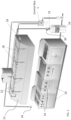
FIG. 1 is a schematic diagram of an exemplary system for delivering a fire suppression agent to at least one cooking appliance according to an embodiment; -
FIG. 2 is a perspective view of an exemplary manual activation system for use in a system for delivering fire suppression agent according to an embodiment; -
FIG. 3 is a front view of the manual activation system ofFIG. 2 according to an embodiment; -
FIG. 4 is a perspective view of a portion of the manual activation system ofFIG. 2 according to an embodiment; -
FIG. 5 is a rear view of the portion of the manual activation system ofFIG. 4 according to an embodiment; and -
FIG. 6 is a perspective view of the portion of the manual activation system ofFIG. 4 when the activation member is removed according to an embodiment. - A detailed description of one or more embodiments of the disclosed apparatus and method are presented herein by way of exemplification and not limitation with reference to the Figures.
- With reference now to
FIG. 1 , an example of a system 20 for delivering a fire suppression agent to one ormore cooking appliances 10 is illustrated. The fire suppression system 20 may be located separate or remotely from thecooking appliance 10, such as within avent hood 12, or alternatively, may be integrated or housed at least partially within a portion of thecooking appliance 10. It should be understood that the configuration of the delivery system 20 will vary based on the overall structural design of thecooking appliance 10. The fire suppression system 20 includes one ormore spray nozzles 22 associated with thecooking appliance 10 and a source offire suppression agent 24 in the form of a self-contained pressure vessel. In embodiments including a plurality ofcooking appliances 10, one ormore spray nozzles 22 may be dedicated to eachcooking appliance 10, or alternatively, one or more evenly spacedspray nozzles 22 may be used for all of thecooking appliances 10. The source offire suppression agent 24 is arranged in fluid communication with thenozzles 22 via an agent delivery path defined by adelivery piping system 26. In the event of a fire, the fire suppression agent is allowed to flow through thedelivery piping system 26 to the one ormore spray nozzles 22 for release directly onto an adjacentcooking hazard area 14 of the one ormore cooking appliances 10. - Those skilled in the art will readily appreciate that the fire suppression agent can be selected from materials such as water, dry chemical agent, wet chemical agent, or the like. Further, the source of
fire suppression agent 24 may additionally contain a gas propellant for facilitating the movement of the fire suppression agent through thedelivery piping system 26. However, embodiments where the propellant is stored separately from the fire suppression agent are also contemplated herein. - In an embodiment, the fire suppression system 20 is actuated in response to a fire sensing device (illustrated schematically at 28), such as a smoke detector or a heat sensor for example. In response to detecting heat or smoke exceeding an allowable limit, a control box C will direct a signal to an
actuator 30 to open avalve 32 to allow the fire suppression agent to flow from thesource 24 to thenozzles 22. Alternatively, or in addition, the fire suppression system 20 includes amanual activation system 34, also referred to herein as a pull station, configured to actuate the control box C to activate thevalve 32 to initiate operation of the fire suppression system 20. - With reference now to
FIGS. 2-6 , an example of amanual activation system 34 is illustrated in more detail. Themanual activation system 34 includes ahousing 40 having apulley 42 rotatably mounted to pin. 44. Thepin 44 is supported by abracket 46. Although thebracket 46 is illustrated as being generally U shaped or C-shaped and connected to thepin 44 at opposite sides of thepulley 42 along the axis X of rotation of thepin 44, it should be understood that any suitable bracket is within the scope of the disclosure. Atension member 48, such as a rope or cable for example, is wrapped about a portion of thepulley 42 and is operably coupled to the control box C of the delivery system 20. However, it should be understood that embodiments where thetension member 48 is operably coupled directly to theactuator 30 are also within the scope of the disclosure. - The
pulley 42 is movable within thehousing 40 between an inactive position and an active position. In the inactive position, as shown inFIGS. 2-5 , thetension member 48 applies a force (e.g., tension) on the control box C for the delivery system 20 to be in an inactive state. When thepulley 42 transforms to an active position, such as by moving vertically within thehousing 40, this tension within thecable 48, and therefore the force applied in the control box C is reduced. In response, the control box C will transmit an electrical or pneumatic signal to theactuator 30 to activate the delivery system 20. - The
manual activation system 34 additionally includes amechanical assembly 50 configured to maintain thepulley 42 in an inactive position. Themechanical assembly 50 includes at least one link arm pivotally or rotatably mounted to thehousing 40 via a shaft. The at least one link arm is operably coupled to thepulley 42 to selectively oppose the tensile force acting on thepulley 42. The at least one link arm may be configured to rotate relative to the shaft, or alternatively, the at least one link arm may be fixedly mounted to the shaft and the shaft may be rotatably mounted to thehousing 40. In the illustrated, non-limiting embodiment, themechanical assembly 50 includes a twolink arms housing 40 via tworespective shafts first link arm 52a and the second link arm are 52b illustrated as being substantially identical but mounted as mirror images of one another, embodiments where thefirst link arm 52a and thesecond link arm 52b have different configurations are also within the scope of the disclosure. - The
first shaft 54a and thesecond shaft 54b may, but need not be arranged parallel to one another. Further, thefirst link arm 52a and thesecond link arm 52b may be arranged adjacent opposing sides of thebracket 46. In the illustrated, non-limiting embodiment, the first andsecond link arms bracket 46. - In an embodiment, at least one biasing mechanism, such as a torsion spring for example, is operably coupled to the at least one link arm. In embodiments where the
link arm shaft mechanisms FIG. 5 , may be mounted to theshafts link arm shaft biasing mechanism link arm biasing mechanism link arm bracket 46. In embodiments where themechanical assembly 50 has a first andsecond link arm bracket 46, the first andsecond link arm - When the
pulley 42 and therefore themanual activation system 34 is in an inactive position, the at least onelink arm pulley 42 by thetension member 48. In the inactive position, the at least onelink arm bracket 46. In an embodiment, thebracket 46 includes afeature 58 having at least onecontoured surface 60 and the at least onelink arm 52, 52b includes anengagement surface bracket 46, such as the contouredsurface 60 of thefeature 58. In embodiments where themechanical assembly 50 includes afirst link arm 52a and asecond link arm 52b, the feature may similarly include a first and second contouredsurface 60, respectively. This engagement between thelink arms bracket 46, and therefore thepulley 42, in response to the tensile force acting on thetension member 48. - A contour of the engagement surface and the contoured surface may be generally complementary to one another. In the illustrated, non-limiting embodiment, the
contoured surfaces 60 and theengagement surfaces link arm feature 58 is made over the substantiallyentire engagement surface surfaces - An
activation member 64 is configured to cooperate with the one ormore link arms pulley 42. In the illustrated, non-limiting embodiment, theactivation member 64 may be a U-shaped or C-shaped channel having twoarms housing 40, the twoarms activation member 64 are positioned directly adjacent and in contact with the first andsecond link arm arms activation member 64 oppose the biasing force of the biasingmechanisms link arms bracket 46, such as the contouredsurface 60. Thearms activation member 64 may therefore have any configuration such that thearms respective link arm - With reference now to
FIG. 6 , to operate themanual activation system 34, a user moves theactivation member 64 away from the remainder of themechanical assembly 50 and thehousing 40. In an embodiment, theactivation member 64 is moved laterally, out of the plane of rotation of thelink arms activation member 64 may have a handle orother feature 68 to facilitate a user's manipulation of theactivation member 64. Upon removing theactivation member 64, the biasing force of the biasingmechanisms link arms pulley 42 will cause thelink arms bracket 46. Without thelink arms tension member 48, the pulley is free to move within thehousing 40 from the inactive position to the active position, thereby sending a signal to the control box C via a lack of cable tension. - By retaining the
pulley 42 andbracket 46 in the inactive position via themechanical assembly 50, themanual activation system 34 as illustrated and described herein does not require a user to move a component to which the tensile force of the tension member is applied. Accordingly, the force required to activate theactivation system 34 by a user is limited. - The term "about" is intended to include the degree of error associated with measurement of the particular quantity based upon the equipment available at the time of filing the application.
- The terminology used herein is for the purpose of describing particular embodiments only and is not intended to be limiting of the present disclosure. As used herein, the singular forms "a", "an" and "the" are intended to include the plural forms as well, unless the context clearly indicates otherwise. It will be further understood that the terms "comprises" and/or "comprising," when used in this specification, specify the presence of stated features, integers, steps, operations, elements, and/or components, but do not preclude the presence or addition of one or more other features, integers, steps, operations, element components, and/or groups thereof.
- While the present disclosure has been described with reference to an exemplary embodiment or embodiments, it will be understood by those skilled in the art that various changes may be made and equivalents may be substituted for elements thereof without departing from the scope of the present disclosure. In addition, many modifications may be made to adapt a particular situation or material to the teachings of the present disclosure without departing from the essential scope thereof. Therefore, it is intended that the present disclosure not be limited to the particular embodiment disclosed as the best mode contemplated for carrying out this present disclosure, but that the present disclosure will include all embodiments falling within the scope of the claims.
Claims (15)
- A manual activation system comprising:a housing;a pulley arranged within the housing, the pulley being movable between an inactive position and an active position;a tension member wrapped about the pulley, the tension member having a tensile force acting on the pulley; andat least one link arm rotatably mounted within the housing, wherein the at least one link arm is operably coupled to the pulley to selectively oppose the tensile force acting on the pulley.
- The manual activation system of claim 1, wherein the pulley is mounted within a bracket, and when in the inactive position, the at least one link arm is engaged with a portion of the bracket.
- The manual activation system of claim 2, wherein the bracket further comprises a contoured surface and the at least one link arm further comprises an engagement surface, the engagement surface being engaged with the contoured surface when the pulley is in the inactive position; preferably
wherein a contour of the engagement surface is complementary to a contour of the contoured surface. - The manual activation system of claim 3, wherein the engagement surface and the contoured surface are sloped surfaces having identical angles.
- The manual activation system of any preceding claim, further comprising an activation member selectively coupled to the at least one link arm when the pulley is in the inactive position; preferablyfurther comprising at least one biasing mechanism operably coupled to the at least one link arm, the at least one biasing mechanism being configured to apply a biasing force on the at least one link arm in a direction away from the pulley; and more preferablywherein the activation member opposes the biasing force of the at least one biasing mechanism.
- The manual activation system of any preceding claim, wherein the tension member is operably coupled to an actuator or a control box of a fire suppression system.
- A manual activation system comprising:a pulley mounted within a bracket, the pulley and the bracket being movable between an inactive position and an active position;a tension member wrapped about the pulley, the tension member having a tensile force acting on the pulley; anda mechanical assembly selectively coupled to the bracket to oppose the tensile force acting on the pulley.
- The manual activation system of claim 7, wherein the bracket further comprises a feature having a contoured surface and a portion of the mechanical assembly is engaged with the contoured surface when the pulley and the bracket are in the inactive position.
- The manual activation system of claim 8, wherein the mechanical assembly further comprises at least one link arm rotatable to selectively engage the contoured surface.
- The manual activation system of claim 9, wherein the mechanical assembly further comprises an activation member positioned adjacent to the at least one link arm, wherein the activation member restricts movement of the at least one link arm out of engagement with the contoured surface; preferablywherein the mechanical assembly further comprises a biasing mechanism operably coupled to the at least one link arm, the biasing mechanism being configured to apply a biasing force on the at least one link arm in a direction away from the bracket; more preferablywherein the activation member opposes the biasing force of the biasing mechanism.
- The manual activation system of any of claims 7 to 10, wherein the tension member is operably coupled to an actuator of a fire suppression system.
- A method of operating a manual activation system comprising:
moving an activation member out of engagement with at least one link arm, the movement of the activation member out of engagement with the at least one link arm enabling:(i) the at least one link arm to rotate out of engagement with a bracket, and(ii) the bracket and a pulley coupled to the bracket to move to an active position in response to a tensile force acting on the pulley by a tension member. - The method of claim 12, wherein the at least one link arm rotating out of engagement with the bracket further enables the at least one link arm to be biased in a direction away from the bracket via a biasing mechanism.
- The method of claim 12 or 13, wherein the at least one link arm rotating out of engagement with the bracket occurs at least partially in response to the tensile force acting on the pulley.
- The method of claim 12, 13 or 14, wherein moving the activation member further comprises moving the activation member laterally out of a plane of rotation of the at least one link arm.
Applications Claiming Priority (1)
| Application Number | Priority Date | Filing Date | Title |
|---|---|---|---|
| US202163271383P | 2021-10-25 | 2021-10-25 |
Publications (2)
| Publication Number | Publication Date |
|---|---|
| EP4169585A1 true EP4169585A1 (en) | 2023-04-26 |
| EP4169585B1 EP4169585B1 (en) | 2026-03-18 |
Family
ID=83692808
Family Applications (1)
| Application Number | Title | Priority Date | Filing Date |
|---|---|---|---|
| EP22201391.4A Active EP4169585B1 (en) | 2021-10-25 | 2022-10-13 | Cable pull station release mechanism |
Country Status (3)
| Country | Link |
|---|---|
| US (1) | US12228959B2 (en) |
| EP (1) | EP4169585B1 (en) |
| ES (1) | ES3066245T3 (en) |
Cited By (2)
| Publication number | Priority date | Publication date | Assignee | Title |
|---|---|---|---|---|
| EP4205817A1 (en) * | 2022-01-04 | 2023-07-05 | Carrier Corporation | Pull station release mechanism |
| EP4260916A1 (en) * | 2022-04-11 | 2023-10-18 | Carrier Corporation | Hinged axle pulley release for inline cable fire pull station |
Citations (2)
| Publication number | Priority date | Publication date | Assignee | Title |
|---|---|---|---|---|
| US5127479A (en) * | 1990-12-31 | 1992-07-07 | 21St Century International Fire Equipment Services Corporation | Fire extinguishing system for cookstoves and ranges |
| US5297636A (en) * | 1990-12-31 | 1994-03-29 | Twenty First Century | Fire extinguishing system for cookstoves and ranges |
Family Cites Families (16)
| Publication number | Priority date | Publication date | Assignee | Title |
|---|---|---|---|---|
| US712525A (en) | 1901-11-11 | 1902-11-04 | Robert E Erdman | Fire-alarm signaling apparatus. |
| US2031964A (en) | 1931-04-01 | 1936-02-25 | Kidde & Co Walter | Pull box remote control |
| US2316789A (en) | 1938-06-14 | 1943-04-20 | Specialties Dev Corp | High pressure fluid medium distribution system |
| US2486447A (en) | 1948-01-27 | 1949-11-01 | Specialties Dev Corp | Pull box |
| US3183501A (en) | 1963-04-09 | 1965-05-11 | Autocall Company | Signal station |
| US3356801A (en) | 1966-10-05 | 1967-12-05 | Reeve Electrical Co Inc | Break-glass station |
| US3515218A (en) | 1968-03-11 | 1970-06-02 | Newell J Gardner | Fire safety system |
| US4238971A (en) | 1978-12-18 | 1980-12-16 | United Technologies Corporation | Releasable push-pull sheathed cable control system |
| US4280120A (en) | 1980-04-18 | 1981-07-21 | General Signal Corporation | Fire alarm signal station |
| US4728928A (en) | 1986-05-08 | 1988-03-01 | Fisher Berkeley Corporation | Call switch for wet areas |
| US5871056A (en) | 1997-02-06 | 1999-02-16 | Renna; Edward M. | Totally enclosed fusible disc heat detector |
| US6286604B1 (en) | 2000-05-09 | 2001-09-11 | Ren-Sheng Ou | Powerless automatic and/or manual fire-extinguishing device |
| KR101571772B1 (en) | 2007-03-02 | 2015-11-25 | 타이코 파이어 프로덕츠 엘피 | Fire suppression or emergency annunciation system |
| EP2388227B1 (en) | 2010-05-20 | 2015-01-21 | Rotzler Gmbh + Co. Kg | Crane hook with a hook weight assembly |
| EP2907546B1 (en) * | 2014-02-17 | 2019-03-27 | Minimax GmbH & Co KG | Trigger unit for extinguishing devices |
| DE202017102147U1 (en) | 2017-04-10 | 2017-05-05 | Igus Gmbh | Cable bushing, in particular strain relief for an energy chain |
-
2022
- 2022-10-07 US US17/961,730 patent/US12228959B2/en active Active
- 2022-10-13 EP EP22201391.4A patent/EP4169585B1/en active Active
- 2022-10-13 ES ES22201391T patent/ES3066245T3/en active Active
Patent Citations (2)
| Publication number | Priority date | Publication date | Assignee | Title |
|---|---|---|---|---|
| US5127479A (en) * | 1990-12-31 | 1992-07-07 | 21St Century International Fire Equipment Services Corporation | Fire extinguishing system for cookstoves and ranges |
| US5297636A (en) * | 1990-12-31 | 1994-03-29 | Twenty First Century | Fire extinguishing system for cookstoves and ranges |
Cited By (2)
| Publication number | Priority date | Publication date | Assignee | Title |
|---|---|---|---|---|
| EP4205817A1 (en) * | 2022-01-04 | 2023-07-05 | Carrier Corporation | Pull station release mechanism |
| EP4260916A1 (en) * | 2022-04-11 | 2023-10-18 | Carrier Corporation | Hinged axle pulley release for inline cable fire pull station |
Also Published As
| Publication number | Publication date |
|---|---|
| ES3066245T3 (en) | 2026-05-12 |
| EP4169585B1 (en) | 2026-03-18 |
| US20230126593A1 (en) | 2023-04-27 |
| US12228959B2 (en) | 2025-02-18 |
Similar Documents
| Publication | Publication Date | Title |
|---|---|---|
| EP4169585B1 (en) | Cable pull station release mechanism | |
| US12478812B2 (en) | Pull station release mechanism | |
| US7143977B2 (en) | Force supporting module for providing a load-dependent supporting force | |
| KR100236695B1 (en) | Slide door automatic open/colse device for a vehicle | |
| US3182917A (en) | Brush chipper safety control | |
| EP4260916B1 (en) | Hinged axle pulley release for inline cable fire pull station | |
| US4265316A (en) | Fire extinguishing system having a linkage operated valve | |
| EP1907072A1 (en) | Thermal detector for fire suppression system | |
| US2834416A (en) | Fire fighting apparatus | |
| EP4282494A1 (en) | Torsion release mechanical control node for cable operated fire suppression systems | |
| EP0913960A2 (en) | Emergency control system | |
| EP4245379A1 (en) | Mechanical fire fighting activation | |
| GB2290366A (en) | Apparatus for jointly actuating a pair of valves | |
| US8534676B2 (en) | Remotely controllable rotary switch actuator | |
| CN101448726A (en) | Conveying device | |
| US20230310916A1 (en) | Continuous cable installation of fire detection links | |
| EP4441406B1 (en) | Valve control apparatus and method | |
| JP2003164541A (en) | Fireplug | |
| US3275796A (en) | Arc welding control system | |
| JPH07224865A (en) | Brake gear for saw with prime mover | |
| KR102061122B1 (en) | Filter Device of Overpressure Equipment | |
| CN102832081A (en) | Transmission mechanism in tripper | |
| JP7386532B2 (en) | Wire connection mechanism and wire connection method, fire extinguishing equipment and fire extinguishing method | |
| CN121195821A (en) | An irrigation gate valve | |
| EP0027310B1 (en) | Fire extinguishing system |
Legal Events
| Date | Code | Title | Description |
|---|---|---|---|
| PUAI | Public reference made under article 153(3) epc to a published international application that has entered the european phase |
Free format text: ORIGINAL CODE: 0009012 |
|
| STAA | Information on the status of an ep patent application or granted ep patent |
Free format text: STATUS: THE APPLICATION HAS BEEN PUBLISHED |
|
| AK | Designated contracting states |
Kind code of ref document: A1 Designated state(s): AL AT BE BG CH CY CZ DE DK EE ES FI FR GB GR HR HU IE IS IT LI LT LU LV MC ME MK MT NL NO PL PT RO RS SE SI SK SM TR |
|
| STAA | Information on the status of an ep patent application or granted ep patent |
Free format text: STATUS: REQUEST FOR EXAMINATION WAS MADE |
|
| 17P | Request for examination filed |
Effective date: 20231026 |
|
| RBV | Designated contracting states (corrected) |
Designated state(s): AL AT BE BG CH CY CZ DE DK EE ES FI FR GB GR HR HU IE IS IT LI LT LU LV MC ME MK MT NL NO PL PT RO RS SE SI SK SM TR |
|
| RAP1 | Party data changed (applicant data changed or rights of an application transferred) |
Owner name: KIDDE-FENWAL, LLC |
|
| P01 | Opt-out of the competence of the unified patent court (upc) registered |
Free format text: CASE NUMBER: APP_30600/2025 Effective date: 20250626 |
|
| GRAP | Despatch of communication of intention to grant a patent |
Free format text: ORIGINAL CODE: EPIDOSNIGR1 |
|
| STAA | Information on the status of an ep patent application or granted ep patent |
Free format text: STATUS: GRANT OF PATENT IS INTENDED |
|
| INTG | Intention to grant announced |
Effective date: 20251111 |
|
| GRAS | Grant fee paid |
Free format text: ORIGINAL CODE: EPIDOSNIGR3 |
|
| GRAA | (expected) grant |
Free format text: ORIGINAL CODE: 0009210 |
|
| STAA | Information on the status of an ep patent application or granted ep patent |
Free format text: STATUS: THE PATENT HAS BEEN GRANTED |
|
| AK | Designated contracting states |
Kind code of ref document: B1 Designated state(s): AL AT BE BG CH CY CZ DE DK EE ES FI FR GB GR HR HU IE IS IT LI LT LU LV MC ME MK MT NL NO PL PT RO RS SE SI SK SM TR |
|
| REG | Reference to a national code |
Ref country code: CH Ref legal event code: F10 Free format text: ST27 STATUS EVENT CODE: U-0-0-F10-F00 (AS PROVIDED BY THE NATIONAL OFFICE) Effective date: 20260318 Ref country code: GB Ref legal event code: FG4D |
|
| REG | Reference to a national code |
Ref country code: IE Ref legal event code: FG4D |
|
| REG | Reference to a national code |
Ref country code: DE Ref legal event code: R096 Ref document number: 602022032474 Country of ref document: DE |
|
| REG | Reference to a national code |
Ref country code: ES Ref legal event code: FG2A Ref document number: 3066245 Country of ref document: ES Kind code of ref document: T3 Effective date: 20260512 |