EP4168274B1 - Exterior mounted camera pod adapter - Google Patents
Exterior mounted camera pod adapter Download PDFInfo
- Publication number
- EP4168274B1 EP4168274B1 EP21765853.3A EP21765853A EP4168274B1 EP 4168274 B1 EP4168274 B1 EP 4168274B1 EP 21765853 A EP21765853 A EP 21765853A EP 4168274 B1 EP4168274 B1 EP 4168274B1
- Authority
- EP
- European Patent Office
- Prior art keywords
- camera pod
- pod adapter
- aperture
- adapter
- mounting bracket
- Prior art date
- Legal status (The legal status is an assumption and is not a legal conclusion. Google has not performed a legal analysis and makes no representation as to the accuracy of the status listed.)
- Active
Links
Images






Classifications
-
- B—PERFORMING OPERATIONS; TRANSPORTING
- B60—VEHICLES IN GENERAL
- B60R—VEHICLES, VEHICLE FITTINGS, OR VEHICLE PARTS, NOT OTHERWISE PROVIDED FOR
- B60R11/00—Arrangements for holding or mounting articles, not otherwise provided for
- B60R11/04—Mounting of cameras operative during drive; Arrangement of controls thereof relative to the vehicle
-
- H—ELECTRICITY
- H04—ELECTRIC COMMUNICATION TECHNIQUE
- H04N—PICTORIAL COMMUNICATION, e.g. TELEVISION
- H04N23/00—Cameras or camera modules comprising electronic image sensors; Control thereof
- H04N23/50—Constructional details
- H04N23/51—Housings
-
- B—PERFORMING OPERATIONS; TRANSPORTING
- B60—VEHICLES IN GENERAL
- B60R—VEHICLES, VEHICLE FITTINGS, OR VEHICLE PARTS, NOT OTHERWISE PROVIDED FOR
- B60R1/00—Optical viewing arrangements; Real-time viewing arrangements for drivers or passengers using optical image capturing systems, e.g. cameras or video systems specially adapted for use in or on vehicles
- B60R1/12—Mirror assemblies combined with other articles, e.g. clocks
- B60R2001/1253—Mirror assemblies combined with other articles, e.g. clocks with cameras, video cameras or video screens
Definitions
- the present disclosure relates a camera pod adapter assembly.
- the present disclosure relates to the mounting of a camera pod to the exterior of a vehicle. It also refers to a vehicle with such a camera pod adapter assembly.
- US 2017/225628 A1 describes an apparatus for mounting a camera to a vehicle, the apparatus comprising a motor; a rotatable shaft operatively coupled to the motor, wherein the rotatable shaft includes a mechanism for mounting a camera; and a controller coupled to the motor and configured to control rotation of the rotatable shaft based on a desired orientation of the camera.
- US 10,232,780 B1 refers to a vehicle camera cover assembly, comprising a base bracket having a windshield attachment surface and a cover attachment surface opposite the windshield attachment surface, the base bracket defining an opening dimensioned to encircle a base member of a rear-view mirror, the cover attachment surface having an upper portion with a first attachment section, a lower portion with a second attachment section and midportion with an inner flange extending therefrom at a location spaced apart from the first attachment section and the second attachment section; an upper cover having an upper attachment section that aligns with and attaches to the first attachment section, the upper cover having a retention flange extending from one end thereof dimensioned and positioned to overlay the inner flange of the base bracket with the upper cover attached to the base bracket; and a lower cover having a lower attachment section that aligns with and removably connects to the second attachment section, the lower cover having an outer flange dimensioned and positioned such that with the upper cover and the lower cover installed to the base bracket, the outer flange
- DE 10 2016 110 748 B3 relates to a folding joint for attaching a rear view display device to a vehicle, comprising: a first hinge portion and a second hinge portion, wherein the first and second hinge portions are designed to be mutually about a pivot axis to be rotatable around; and a hinge pin which at least partially coincides with the axis of rotation, the hinge pin being adapted to pivotally connect the first and second hinge sections to one another, wherein the hinge pin comprises a guide pin extending substantially perpendicularly from the hinge pin and a spring-loaded clamping bolt arranged on the guide pin, the spring-loaded clamping bolt comprising a cam portion and adapted to cooperate with at least one locking surface in the second hinge portion to adjustably lock relative to pivotal movement of the first and second hinge portions.
- a camera pod adapter assembly for mounting to an exterior of a vehicle, comprising: a camera pod adapter providing a mounting point for a camera pod system and mounting brackets; an attachment portion on a vehicle side for attachment of the camera pod adapter to the vehicle comprising at least one aperture; and fasteners, which can be turned in order to tighten the mounting brackets; wherein the fasteners are rotatable in such a way that the mounting brackets are in a first state in which they are extended the maximum distance away from the camera pod adapter, whereby in the first state, the mounting brackets are aligned such that they are able to be inserted through the respective aperture, and wherein the fasteners are rotatable in such a way that the mounting brackets are in a second state in which they are retracted such that they are a minimum distance away from the camera pod adapter, whereby, in the second state, the mounting brackets abut against the inner surface of the attachment portion, fixing the camera pod adapter in place.
- the adapter assembly is provided with a mounting side for attachment of a camera pod assembly, and a vehicle side for attachment to a vehicle.
- the adapter assembly thus, is provided with fastners and mounting brackets which cooperatively fix the adapter assembly to the attachment portion of a vehicle.
- the adapter assembly has mounting brackets having a first state and a second state.
- the fasteners are operable to move the mounting brackets from the first state to the second state.
- the fasteners are also operable to move the mounting brackets from the second state to the first state.
- the at least one first aperture is provided substantially perpendicular to the at least one mounting brackets; and the fastners are operable to be inserted through the at least one first aperture to fix the adapter assembly.
- One general aspect of the adapter assembly may include at least one first aperture and an at least one second fastener. wherein one embodiment the at least one first aperture of the camera pod adapter assembly provided herein is provided substantially perpendicular to the at least one mounting bracket. The at least one second fastener is operable to be inserted through the at least one first aperture to fix the adapter assembly.
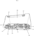
- FIG. 1 illustrates an isometric view of a camera pod adapter in accordance with aspects of the present disclosure.
- the mounting side 102 of camera pod adapter 100 is shown, which provides a mounting point for a camera pod system (not shown).
- a camera pod system may be attached to the mounting side 102 of camera pod adapter 100 via camera pod system mount 114.
- Aperture 104 provides an opening for a wiring harness (not shown) to pass from the vehicle through camera pod adapter 100 to a camera pod system.
- the camera pod system may come equipped with an integrated self-cleaning system which would require a tube for a cleaning fluid, which could be passed through aperture 104.
- Screw 106 and screw 108 are provided and can be turned in order to tighten mounting bracket 116 and mounting bracket 118 respectively (shown in FIG. 2 ).
- Aperture 110 and aperture 112 provide openings through which a fastener (not shown) may be insert to secure camera pod adapter 100 to the exterior of a vehicle.
- screw 106 and screw 108 are depicted as screws, however in other embodiments, screw 106 and screw 108 may be any other known fastener or fastening method.
- FIG. 2 illustrates an isometric view of a camera pod adapter in accordance with aspects of the present disclosure.
- the vehicle side 120 of camera pod adapter 100 is shown.
- Mounting bracket 116 comprises a threaded insert in which screw 106 is inserted. When screw 106 is turned clockwise, it will pull mounting bracket 116 towards camera pod adapter 100, and when the screw 106 is turned counter-clockwise, it will push mounting bracket 116 away from camera pod adapter 100.
- mounting bracket 118 comprises a threaded insert in which screw 108 is inserted such that when the screw 108 is turned clockwise the mounting bracket 118 is pulled towards camera pod adapter 100 and when screw 108 is turned counter-clockwise the mounting bracket 118 is pushed away from camera pod adapter 100.
- camera pod adapter 100 comprises two mounting brackets, mounting bracket 116 and mounting bracket 118.
- camera pod adapter 100 requires at least one or more mounting brackets.
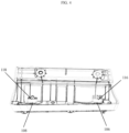
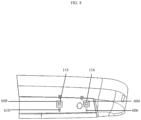
- FIG. 3 and FIG. 4 illustrate a side view of the mounting brackets of a camera pod adapter in accordance with aspects of the present disclosure.
- FIG. 3 depicts screw 106 and screw 108 having been rotated such that mounting bracket 116 and mounting bracket 118 are in a first state in which they are extended the maximum distance away from camera pod adapter 100.
- FIG. 4 depicts screw 106 and screw 108 having been rotated such that mounting bracket 116 and mounting bracket 118 are in a second state in which they are retracted such that they are a minimum distance away from camera pod adapter 100, i.e. in a position contrary to the first state.
- FIG. 5 depicts a close up view of a mounting bracket and camera pod adapter in accordance with aspects of the present disclosure.
- Mounting bracket 118 is attached to screw 108 which may be used to move mounting bracket 118 from a first state to a second state or from a second state to a first state.
- camera pod adapter 100 additionally includes guide 502 and guide 504.
- Guide 502 and guide 504 are fixed to camera pod adapter 100 such that guide 502 extends into aperture 506 and guide 504 extends into aperture 508, where aperture 506 and aperture 508 are located on mounting bracket 118.
- Guide 502 and guide 504 stabilize the mounting bracket 118 so that it remains fixed in place during the installation of camera pod adapter 100 which will be discussed further with additional reference to Figs. 6-13 .
- Mounting bracket 116 also has guides and apertures similar to guide 502, guide 504, aperture 506, and aperture 508 in form and function. However for the sake of clarity, only the exemplary guides used to stabilize mounting bracket 118 are shown in subsequent figures.
- FIG. 6 illustrates an isometric view of an attachment portion 600 of a vehicle for the attachment of a camera pod adapter 100 in accordance with aspects of the present disclosure.
- Attachment portion 600 may be located on a vehicle where it is desired to attach a camera pod.
- Aperture 602 provides an opening for a wiring harness or tube (not shown) to pass from the vehicle through camera pod adapter 100 to a camera pod system.
- Aperture 604 provides an opening through which the mounting bracket 118 may be inserted and aperture 608 provides an opening through which the mounting bracket 116 may be inserted.
- Slot 606 is connected to the aperture 604 and provides a space for the screw to be adjusted.
- the slot 610 is connected to aperture 608 in order to provide a space for the adjustment of screw 106.
- a fastener (not shown) may be inserted through aperture 110 of the camera pod adapter 100 and into aperture 612 as well as through aperture 112 of the camera pod adapter 100 and into aperture 614 in order to fix camera pod adapter 100 to attachment portion
- FIG. 7 illustrates a perspective view of the alignment of camera pod adapter 100 and attachment portion 600 in accordance with aspects of the present disclosure.
- the mounting bracket 116 and the mounting bracket 118 To install the camera pod adapter 100 at attachment portion 600, the mounting bracket 116 and the mounting bracket 118 must be in a first state in which they are the maximum distance away from camera pod adapter 100. In the first state, the mounting bracket 116 is aligned such that it is able to be inserted through aperture 604 and the mounting bracket 118 is aligned such that it is able to be inserted through aperture 608.
- the alignment of the mounting bracket 116 to aperture 604 and the mounting bracket 118 to aperture 608 can be seen in more clearly in Figs. 8-9 .
- the mounting bracket 116 is inserted through aperture 604 and mounting bracket 118 is inserted through aperture 608, there is a distance between camera pod adapter 100 and mounting the attachment portion 600, which is shown by distance 900 in FIG. 9 .
- Aligning the mounting brackets 116, 118 of camera pod adapter 100 to pass through their respective apertures means that a portion of screw 106, guide 502, and guide 504 will pass through aperture 604 and that a portion of screw 108 and its respective guides will pass through aperture 608.
- camera pod adapter 100 may be fit onto attachment portion 600.
- screw 106, guide 502, and guide 504 are repositioned from aperture 604 into slot 606 while simultaneously screw 108 and the respective guides of mounting bracket 116 are repositioned from aperture 608 into slot 610 allowing vehicle side 120 of camera pod adapter 100 to rest against the surface of attachment portion 600 as shown in Figs.
- the length of slot 606 and slot 610 corresponds to distance 900 of FIG. 9 such that when camera pod adapter 100 is moved towards attachment portion 600, distance 900 reduces until the camera pod adapter 100 contacts the attachment portion 600.
- the distance 900 is approximately zero at the point of contact.
- the installation of the camera pod adapter 100 to the attachment portion 600 is performed easily in comparison to the current state of the art.
- Conventional adapters do not comprise the mounting bracket 116 or the mounting bracket 118 and generally only include screw 106 and screw 108.
- the camera pod adapter 100 must be held in place while screw 106 and screw 108 are adjusted such that they line up with their respective apertures on attachment portion 600. This can be difficult operation for a person to perform since one hand is used to hold camera pod adapter 100 in place.
- the alignment and turning of screw 106 and screw 108 must be done with a single free hand while simultaneously holding a screwdriver, drill, or other means of rotating the screw 106 and the screw 108 into their respective apertures.
- the mounting bracket 116 and the mounting bracket 118 are no longer aligned with aperture 604 or aperture 608 as shown previously in FIG. 10 .
- the mounting bracket 116 and the mounting bracket 118 abut against the inner surface of attachment portion 600, fixing camera pod adapter 100 in place.
- FIG. 12 illustrates a camera pod adapter being attached to an attachment portion of a vehicle in accordance with aspects of the present disclosure.
- a fastener (not shown) may be insert through aperture 110 ( Fig. 2 ) into aperture 612 ( Fig. 6 ) and through aperture 112 ( Fig. 2 ) into aperture 614 ( Fig. 6 ) and then tightened in order to secure camera pod adapter 100 to attachment portion 600.
- the insertion of fasteners through aperture 110 and aperture 112 into aperture 612 and aperture 614 secures camera pod adapter 100 along an axis substantially perpendicular to that of mounting bracket 116 and mounting bracket 118.
- the mounting bracket 116 and the mounting bracket 118 secure camera pod adapter 100 by applying force against attachment portion 600 adjacent to slot 606 and slot 610. However, if only mounting bracket 116 and mounting bracket 118 are used, it would be possible to remove camera pod adapter 100 by applying an upward force relative to the camera pod adapter 100.
- the use of fasteners insert through aperture 110 into aperture 612 and through aperture 112 into aperture 614 prevents camera pod adapter 100 from being removed from attachment portion 600 by the application of an upward force.
- the gasket 122 is compressed between camera pod adapter 100 and the outer surface of attachment portion 600. Once fully compressed, the gasket 122 is able to seal any openings between camera pod adapter 100 and attachment portion 600 in order to prevent the intrusion of contaminants from the atmosphere external to the camera pod adapter to enter into the equipped vehicle.
Landscapes
- Engineering & Computer Science (AREA)
- Mechanical Engineering (AREA)
- Multimedia (AREA)
- Signal Processing (AREA)
- Fittings On The Vehicle Exterior For Carrying Loads, And Devices For Holding Or Mounting Articles (AREA)
Description
- The present disclosure relates a camera pod adapter assembly. In particular, the present disclosure relates to the mounting of a camera pod to the exterior of a vehicle. It also refers to a vehicle with such a camera pod adapter assembly.
- Current motor vehicle rear view mirror systems which enable the driver to view indirect fields of view are being replaced by camera systems. In order to monitor the required viewing zones, the camera system must be arranged in a specific layout in regard to frontal position and lateral spacing from the vehicle. The specified mounting location of the camera pod adapter assembly and it's method of installation may present disadvantages in the mounting process.
-
US 2017/225628 A1 describes an apparatus for mounting a camera to a vehicle, the apparatus comprising a motor; a rotatable shaft operatively coupled to the motor, wherein the rotatable shaft includes a mechanism for mounting a camera; and a controller coupled to the motor and configured to control rotation of the rotatable shaft based on a desired orientation of the camera. -
US 10,232,780 B1 -
DE 10 2016 110 748 B3 relates to a folding joint for attaching a rear view display device to a vehicle, comprising: a first hinge portion and a second hinge portion, wherein the first and second hinge portions are designed to be mutually about a pivot axis to be rotatable around; and a hinge pin which at least partially coincides with the axis of rotation, the hinge pin being adapted to pivotally connect the first and second hinge sections to one another, wherein the hinge pin comprises a guide pin extending substantially perpendicularly from the hinge pin and a spring-loaded clamping bolt arranged on the guide pin, the spring-loaded clamping bolt comprising a cam portion and adapted to cooperate with at least one locking surface in the second hinge portion to adjustably lock relative to pivotal movement of the first and second hinge portions. - It is the object of this disclosure to further develop the existing camera pod mountings to overcome the problems of the prior art.
- The object is achieved by the provision of a camera pod adapter assembly for mounting to an exterior of a vehicle, comprising: a camera pod adapter providing a mounting point for a camera pod system and mounting brackets; an attachment portion on a vehicle side for attachment of the camera pod adapter to the vehicle comprising at least one aperture; and fasteners, which can be turned in order to tighten the mounting brackets; wherein the fasteners are rotatable in such a way that the mounting brackets are in a first state in which they are extended the maximum distance away from the camera pod adapter, whereby in the first state, the mounting brackets are aligned such that they are able to be inserted through the respective aperture, and wherein the fasteners are rotatable in such a way that the mounting brackets are in a second state in which they are retracted such that they are a minimum distance away from the camera pod adapter, whereby, in the second state, the mounting brackets abut against the inner surface of the attachment portion, fixing the camera pod adapter in place. The adapter assembly is provided with a mounting side for attachment of a camera pod assembly, and a vehicle side for attachment to a vehicle. The adapter assembly, thus, is provided with fastners and mounting brackets which cooperatively fix the adapter assembly to the attachment portion of a vehicle.
- The adapter assembly has mounting brackets having a first state and a second state. The fasteners are operable to move the mounting brackets from the first state to the second state. The fasteners are also operable to move the mounting brackets from the second state to the first state. The at least one first aperture is provided substantially perpendicular to the at least one mounting brackets; and the fastners are operable to be inserted through the at least one first aperture to fix the adapter assembly.
- One general aspect of the adapter assembly may include at least one first aperture and an at least one second fastener. wherein one embodiment the at least one first aperture of the camera pod adapter assembly provided herein is provided substantially perpendicular to the at least one mounting bracket. The at least one second fastener is operable to be inserted through the at least one first aperture to fix the adapter assembly.
- It should be noted that the features set out individually in the following description can be combined with each other in any technically advantageous manner and set out other forms of the present disclosure. The description further characterizes and specifies the present disclosure in particular in connection with the figures.
- In order that the disclosure may be well understood, there will now be described various forms thereof, given by way of example, reference being made to the accompanying drawings, in which:
- FIG. 1
- illustrates an isometric view of a camera pod adapter in accordance with aspects of the present disclosure;
- FIG. 2
- illustrates an isometric view of a camera pod adapter in accordance with aspects of the present disclosure;
- FIG. 3
- illustrate a side view of the mounting brackets of a camera pod adapter in accordance with aspects of the present disclosure;
- FIG. 4
- illustrate a side view of the mounting brackets of a camera pod adapter in accordance with aspects of the present disclosure;
- FIG. 5
- depicts a close up view of a mounting bracket and camera pod adapter in accordance with aspects of the present disclosure;
- FIG. 6
- illustrates an isometric view of an attachment portion of a vehicle for the attachment of a camera pod adapter in accordance with aspects of the present disclosure;
- FIG. 7
- illustrates a perspective view of the alignment of a camera pod adapter and an attachment portion in accordance with aspects of the present disclosure;
- FIG. 8
- illustrates a perspective view of the alignment of mounting brackets of a camera pod adapter with an attachment portion in accordance with aspects of the present disclosure;
- FIG. 9
- illustrates a side view of a camera pod adapter being attached to an attachment portion of a vehicle in accordance with aspects of the present disclosure;
- FIG. 10
- illustrates a perspective view of the alignment of mounting brackets of a camera pod adapter with an attachment portion in accordance with aspects of the present disclosure;
- FIG. 11
- illustrates a side view of the mounting brackets of a camera pod adapter in a first state in accordance with aspects of the present disclosure;
- FIG. 12
- illustrates a side view of the mounting brackets of a camera pod adapter in a second state in accordance with aspects of the present disclosure; and
- FIG. 13
- illustrates a perspective view of a camera pod adapter installed at an attachment portion of a vehicle in accordance with aspects of the present disclosure.
- The following description is merely exemplary in nature and is not intended to limit the present disclosure, application, or uses. It should be understood that throughout the drawings, corresponding reference numerals indicate like or corresponding parts and features.
-
FIG. 1 illustrates an isometric view of a camera pod adapter in accordance with aspects of the present disclosure. InFIG. 1 , themounting side 102 ofcamera pod adapter 100 is shown, which provides a mounting point for a camera pod system (not shown). A camera pod system may be attached to themounting side 102 ofcamera pod adapter 100 via camerapod system mount 114. Aperture 104 provides an opening for a wiring harness (not shown) to pass from the vehicle throughcamera pod adapter 100 to a camera pod system. In other embodiments, the camera pod system may come equipped with an integrated self-cleaning system which would require a tube for a cleaning fluid, which could be passed throughaperture 104. Screw 106 andscrew 108 are provided and can be turned in order to tightenmounting bracket 116 and mountingbracket 118 respectively (shown inFIG. 2 ). Aperture 110 andaperture 112 provide openings through which a fastener (not shown) may be insert to securecamera pod adapter 100 to the exterior of a vehicle. In this embodiment,screw 106 andscrew 108 are depicted as screws, however in other embodiments,screw 106 andscrew 108 may be any other known fastener or fastening method. -
FIG. 2 illustrates an isometric view of a camera pod adapter in accordance with aspects of the present disclosure. InFIG. 2 , thevehicle side 120 ofcamera pod adapter 100 is shown.Mounting bracket 116 comprises a threaded insert in whichscrew 106 is inserted. Whenscrew 106 is turned clockwise, it will pull mountingbracket 116 towardscamera pod adapter 100, and when thescrew 106 is turned counter-clockwise, it will push mountingbracket 116 away fromcamera pod adapter 100. Similarly,mounting bracket 118 comprises a threaded insert in whichscrew 108 is inserted such that when thescrew 108 is turned clockwise themounting bracket 118 is pulled towardscamera pod adapter 100 and whenscrew 108 is turned counter-clockwise themounting bracket 118 is pushed away from camera podadapter 100. It should be noted that the described rotation ofscrew 106 andscrew 108 are exemplary in nature and that the directions could easily be reversed. Further, it should be obvious to anyone skilled in the art that any number of different fastening methods could be used to retract or extend each of mountingbracket 116 and mountingbracket 118 away or towardscamera pod adapter 100. Agasket 122 is arranged such that it may provide a seal betweenvehicle side 120 ofcamera pod adapter 100 and the surface ofattachment portion 600 ofFIG. 6 . In this example variation,camera pod adapter 100 comprises two mounting brackets, mountingbracket 116 and mountingbracket 118. However, in other example variationscamera pod adapter 100 requires at least one or more mounting brackets. -
FIG. 3 andFIG. 4 illustrate a side view of the mounting brackets of a camera pod adapter in accordance with aspects of the present disclosure.FIG. 3 depictsscrew 106 and screw 108 having been rotated such that mountingbracket 116 and mountingbracket 118 are in a first state in which they are extended the maximum distance away fromcamera pod adapter 100.FIG. 4 depictsscrew 106 and screw 108 having been rotated such that mountingbracket 116 and mountingbracket 118 are in a second state in which they are retracted such that they are a minimum distance away fromcamera pod adapter 100, i.e. in a position contrary to the first state. -
FIG. 5 depicts a close up view of a mounting bracket and camera pod adapter in accordance with aspects of the present disclosure. Mountingbracket 118 is attached to screw 108 which may be used to move mountingbracket 118 from a first state to a second state or from a second state to a first state. As shown,camera pod adapter 100 additionally includesguide 502 and guide 504.Guide 502 and guide 504 are fixed tocamera pod adapter 100 such thatguide 502 extends into aperture 506 and guide 504 extends intoaperture 508, where aperture 506 andaperture 508 are located on mountingbracket 118.Guide 502 and guide 504 stabilize the mountingbracket 118 so that it remains fixed in place during the installation ofcamera pod adapter 100 which will be discussed further with additional reference toFigs. 6-13 . Mountingbracket 116 also has guides and apertures similar to guide 502, guide 504, aperture 506, andaperture 508 in form and function. However for the sake of clarity, only the exemplary guides used to stabilize mountingbracket 118 are shown in subsequent figures. -
FIG. 6 illustrates an isometric view of anattachment portion 600 of a vehicle for the attachment of acamera pod adapter 100 in accordance with aspects of the present disclosure.Attachment portion 600 may be located on a vehicle where it is desired to attach a camera pod.Aperture 602 provides an opening for a wiring harness or tube (not shown) to pass from the vehicle throughcamera pod adapter 100 to a camera pod system.Aperture 604 provides an opening through which the mountingbracket 118 may be inserted andaperture 608 provides an opening through which the mountingbracket 116 may be inserted.Slot 606 is connected to theaperture 604 and provides a space for the screw to be adjusted. Theslot 610 is connected toaperture 608 in order to provide a space for the adjustment ofscrew 106. A fastener (not shown) may be inserted throughaperture 110 of thecamera pod adapter 100 and intoaperture 612 as well as throughaperture 112 of thecamera pod adapter 100 and intoaperture 614 in order to fixcamera pod adapter 100 toattachment portion 600. -
FIG. 7 illustrates a perspective view of the alignment ofcamera pod adapter 100 andattachment portion 600 in accordance with aspects of the present disclosure. To install thecamera pod adapter 100 atattachment portion 600, the mountingbracket 116 and the mountingbracket 118 must be in a first state in which they are the maximum distance away fromcamera pod adapter 100. In the first state, the mountingbracket 116 is aligned such that it is able to be inserted throughaperture 604 and the mountingbracket 118 is aligned such that it is able to be inserted throughaperture 608. The alignment of the mountingbracket 116 toaperture 604 and the mountingbracket 118 toaperture 608 can be seen in more clearly inFigs. 8-9 . At the time the mountingbracket 116 is inserted throughaperture 604 and mountingbracket 118 is inserted throughaperture 608, there is a distance betweencamera pod adapter 100 and mounting theattachment portion 600, which is shown bydistance 900 inFIG. 9 . - Aligning the mounting
brackets camera pod adapter 100 to pass through their respective apertures means that a portion ofscrew 106, guide 502, and guide 504 will pass throughaperture 604 and that a portion ofscrew 108 and its respective guides will pass throughaperture 608. Once the mountingbracket 116 and the mountingbracket 118 described above have been extended through their respective apertures,camera pod adapter 100 may be fit ontoattachment portion 600. To fitcamera pod adapter 100 toattachment portion 600,screw 106, guide 502, and guide 504 are repositioned fromaperture 604 intoslot 606 while simultaneously screw 108 and the respective guides of mountingbracket 116 are repositioned fromaperture 608 intoslot 610 allowingvehicle side 120 ofcamera pod adapter 100 to rest against the surface ofattachment portion 600 as shown inFigs. 10-11 . The length ofslot 606 andslot 610 corresponds to distance 900 ofFIG. 9 such that whencamera pod adapter 100 is moved towardsattachment portion 600,distance 900 reduces until thecamera pod adapter 100 contacts theattachment portion 600. Thedistance 900 is approximately zero at the point of contact. - In this manner, the installation of the
camera pod adapter 100 to theattachment portion 600 is performed easily in comparison to the current state of the art. Conventional adapters do not comprise the mountingbracket 116 or the mountingbracket 118 and generally only includescrew 106 andscrew 108. During the installation process, thecamera pod adapter 100 must be held in place whilescrew 106 and screw 108 are adjusted such that they line up with their respective apertures onattachment portion 600. This can be difficult operation for a person to perform since one hand is used to holdcamera pod adapter 100 in place. The alignment and turning ofscrew 106 and screw 108 must be done with a single free hand while simultaneously holding a screwdriver, drill, or other means of rotating thescrew 106 and thescrew 108 into their respective apertures. - As illustrated in
FIG. 11 , oncevehicle side 120 ofcamera pod adapter 100 is brought against the surface ofattachment portion 600,screw 106 and ascrew 108 are turned in order to move mountingbracket 116 and mountingbracket 118 from a first state to a second state where they are a minimum distance away fromcamera pod adapter 100. The mountingbracket 116 and the mountingbracket 118 are translated towardscamera pod adapter 100 when moving from the first state to the second state. Thecamera pod adapter 100 is translated against the surface ofattachment portion 600 by movingscrew 106, guide 502, and guide 504 intoslot 606 as well asscrew 108 and the respective guides of mountingbracket 116 intoslot 610. Thereby, the mountingbracket 116 and the mountingbracket 118 are no longer aligned withaperture 604 oraperture 608 as shown previously inFIG. 10 . When in the second state, the mountingbracket 116 and the mountingbracket 118 abut against the inner surface ofattachment portion 600, fixingcamera pod adapter 100 in place. -
FIG. 12 illustrates a camera pod adapter being attached to an attachment portion of a vehicle in accordance with aspects of the present disclosure. After mountingbracket 116 and mountingbracket 118 are in their second state and are capable to hold thecamera pod adapter 100 againstattachment portion 600, a fastener (not shown) may be insert through aperture 110 (Fig. 2 ) into aperture 612 (Fig. 6 ) and through aperture 112 (Fig. 2 ) into aperture 614 (Fig. 6 ) and then tightened in order to securecamera pod adapter 100 toattachment portion 600. The insertion of fasteners throughaperture 110 andaperture 112 intoaperture 612 andaperture 614 securescamera pod adapter 100 along an axis substantially perpendicular to that of mountingbracket 116 and mountingbracket 118. The mountingbracket 116 and the mountingbracket 118 securecamera pod adapter 100 by applying force againstattachment portion 600 adjacent to slot 606 andslot 610. However, if only mountingbracket 116 and mountingbracket 118 are used, it would be possible to removecamera pod adapter 100 by applying an upward force relative to thecamera pod adapter 100. The use of fasteners insert throughaperture 110 intoaperture 612 and throughaperture 112 intoaperture 614 preventscamera pod adapter 100 from being removed fromattachment portion 600 by the application of an upward force. - As each of the fasteners are inserted through
aperture 110 andaperture 112 along with mountingbracket 116 and mountingbracket 118 being adjusted into a second state, thegasket 122 is compressed betweencamera pod adapter 100 and the outer surface ofattachment portion 600. Once fully compressed, thegasket 122 is able to seal any openings betweencamera pod adapter 100 andattachment portion 600 in order to prevent the intrusion of contaminants from the atmosphere external to the camera pod adapter to enter into the equipped vehicle. - The foregoing description of various preferred embodiments have been presented for purposes of illustration and description. It is not intended to be exhaustive or to limit the disclosure to the precise forms disclosed, and obviously many modifications and variations are possible in light of the above teaching. The example embodiments, as described above, were chosen and described in order to best explain the principles of the disclosure and its practical application to thereby enable others skilled in the art to best utilize the disclosure in various embodiments and with various modifications as are suited to the particular use contemplated. The features of the invention disclosed in the foregoing description, in the drawings and in the claims can be essential for the implementation of the invention in its various embodiments. The extent of the protection conferred by the patent shall be determined by the claims. Nevertheless, the description and drawings shall be used to interpret the claims.
-
- 100 -
- Camera Pod Adapter
- 102 -
- Mounting Side
- 104 -
- Aperture
- 106 -
- Screw
- 108 -
- Screw
- 110 -
- Aperture
- 112 -
- Aperture
- 114 -
- Mount
- 116 -
- Mounting Bracket
- 118 -
- Mounting Bracket
- 120 -
- Vehicle Side
- 122 -
- Gasket
- 502 -
- Guide
- 504 -
- Guide
- 506 -
- Aperture
- 508 -
- Aperture
- 600 -
- Attachment Portion
- 602 -
- Aperture
- 604 -
- Aperture
- 606 -
- Slot
- 608 -
- Aperture
- 610 -
- Slot
- 612 -
- Aperture
- 614 -
- Aperture
- 900 -
- Distance
Claims (5)
- A camera pod adapter assembly for mounting to an exterior of a vehicle, comprising:• a camera pod adapter (100) providing a mounting point for a camera pod system and mounting brackets (116,118);• an attachment portion (600) on a vehicle side (120) for attachment of the camera pod adapter (100) to the vehicle comprising at least one aperture (604, 608);• fasteners (106, 108), which can be turned in order to tighten the mounting brackets (116, 118);whereinthe fasteners (106, 108) are rotatable in such a way that the mounting brackets (116, 118) are in a first state in which they are extended the maximum distance away from the camera pod adapter (100), whereby in the first state, the mounting brackets (116, 118) are aligned such that they are able to be inserted through the respective aperture (604, 608), andthe fasteners (106, 108) are rotatable in such a way that the mounting brackets (116, 118) are in a second state in which they are retracted such that they are a minimum distance away from the camera pod adapter (100), whereby, in the second state, the mounting brackets (116, 118) abut against the inner surface of the attachment portion (600), fixing the camera pod adapter (100) in place.
- The camera pod adapter assembly of claim 1, wherein
the fasteners (106, 108) are screws. - The camera pod adapter assembly of claim 1 or 2, wherein
the camera pod adapter (100) further comprises at least one guide (502, 504) extending into its respective aperture (506, 508) on the attachment portion (600) to stabilize the at least one mounting bracket (116, 118) so that it remains fixed in place during the installation of camera pod adapter 100. - The camera pod adapter assembly of any one of the preceding claims, wherein further a gasket is arranged to provide a seal between a vehicle side (120) of the camera pod adapter (100) and a surface of an attachment portion (600) located on a vehicle.
- A vehicle comprising a camera pod adapter assembly according to any one of the claims 1-4.
Applications Claiming Priority (2)
| Application Number | Priority Date | Filing Date | Title |
|---|---|---|---|
| US202063065619P | 2020-08-14 | 2020-08-14 | |
| PCT/EP2021/072726 WO2022034244A1 (en) | 2020-08-14 | 2021-08-16 | Exterior mounted camera pod adapter |
Publications (2)
| Publication Number | Publication Date |
|---|---|
| EP4168274A1 EP4168274A1 (en) | 2023-04-26 |
| EP4168274B1 true EP4168274B1 (en) | 2024-10-30 |
Family
ID=77640653
Family Applications (1)
| Application Number | Title | Priority Date | Filing Date |
|---|---|---|---|
| EP21765853.3A Active EP4168274B1 (en) | 2020-08-14 | 2021-08-16 | Exterior mounted camera pod adapter |
Country Status (4)
| Country | Link |
|---|---|
| US (1) | US12134357B2 (en) |
| EP (1) | EP4168274B1 (en) |
| CN (1) | CN116171240B (en) |
| WO (1) | WO2022034244A1 (en) |
Citations (2)
| Publication number | Priority date | Publication date | Assignee | Title |
|---|---|---|---|---|
| US20150251605A1 (en) * | 2014-03-10 | 2015-09-10 | Magna Mirrors Of America, Inc. | Vehicle vision system with camera and mirror mount |
| US10766420B2 (en) * | 2016-06-10 | 2020-09-08 | SMR Patents S.à.r.l. | Folding joint for rear view display device |
Family Cites Families (9)
| Publication number | Priority date | Publication date | Assignee | Title |
|---|---|---|---|---|
| US5260731A (en) * | 1992-01-13 | 1993-11-09 | Baker Jr Roy E | Camera mount for a vehicle |
| US8346070B2 (en) * | 2011-04-13 | 2013-01-01 | Beasley Ronald L | Device for supporting a camera in a helicopter |
| KR200468840Y1 (en) | 2013-06-27 | 2013-09-04 | 주식회사 알리온 | Black Box Holding Apparatus for Vehicle |
| US20170225628A1 (en) | 2016-02-09 | 2017-08-10 | Ford Global Technologies, Llc | Motorized Camera Mount |
| US10232780B1 (en) | 2017-10-25 | 2019-03-19 | Nissan North America, Inc. | Vehicle camera cover assembly |
| US10556553B2 (en) * | 2018-05-15 | 2020-02-11 | Veoneer Us, Inc. | Vehicle camera mounting interfaces |
| JP7024634B2 (en) * | 2018-07-09 | 2022-02-24 | Agc株式会社 | Mounting base and vehicle glass with mounting base |
| CN209921171U (en) * | 2019-04-11 | 2020-01-10 | 重庆子粒科技有限公司 | Support and vehicle |
| US11708035B2 (en) * | 2020-07-31 | 2023-07-25 | Magna Mirrors Of America, Inc. | Vehicular imaging system with extendable camera |
-
2021
- 2021-08-16 WO PCT/EP2021/072726 patent/WO2022034244A1/en not_active Ceased
- 2021-08-16 CN CN202180060259.3A patent/CN116171240B/en active Active
- 2021-08-16 EP EP21765853.3A patent/EP4168274B1/en active Active
- 2021-08-16 US US18/005,391 patent/US12134357B2/en active Active
Patent Citations (2)
| Publication number | Priority date | Publication date | Assignee | Title |
|---|---|---|---|---|
| US20150251605A1 (en) * | 2014-03-10 | 2015-09-10 | Magna Mirrors Of America, Inc. | Vehicle vision system with camera and mirror mount |
| US10766420B2 (en) * | 2016-06-10 | 2020-09-08 | SMR Patents S.à.r.l. | Folding joint for rear view display device |
Also Published As
| Publication number | Publication date |
|---|---|
| US20230271565A1 (en) | 2023-08-31 |
| EP4168274A1 (en) | 2023-04-26 |
| CN116171240A (en) | 2023-05-26 |
| CN116171240B (en) | 2025-12-02 |
| US12134357B2 (en) | 2024-11-05 |
| WO2022034244A1 (en) | 2022-02-17 |
Similar Documents
| Publication | Publication Date | Title |
|---|---|---|
| US6145798A (en) | Quick release fan mount | |
| EP3959093B1 (en) | Pivoting cursor for frameless glass in a vehicle | |
| EP1243471B1 (en) | Vehicle mirror device assembly | |
| EP2998160B1 (en) | Method of fixing an apparatus comprising a towing mirror | |
| US20040239574A1 (en) | Positioning device for adjustable housing | |
| CN212125313U (en) | Motor vehicle | |
| US11203306B2 (en) | Dashboard attachment device | |
| JP2887117B2 (en) | Steering wheel attachment to steering shaft | |
| US20130200232A1 (en) | Wall-Mountable Device | |
| US6637363B2 (en) | Adjustable boat windshield support brace | |
| EP1606548B1 (en) | A projector holder | |
| KR20010040566A (en) | Vehicle door prop clip and removal method thereof | |
| US10632897B2 (en) | Alignment element for positioning an attachment part | |
| US6225962B1 (en) | Apparatus and method for an adjustable linkage | |
| EP1570147B1 (en) | An adjustable hinge assembly | |
| KR20030084667A (en) | Device for holding panels and separating element | |
| US12134357B2 (en) | Exterior mounted camera pod adapter | |
| US5116013A (en) | Mirror mounting mechanism | |
| EP2759468A1 (en) | Locking apparatus | |
| US20040079007A1 (en) | Universal license plate holder | |
| US20050160776A1 (en) | Lock module for motor vehicle door | |
| KR20000053462A (en) | Clamping support for securing rearview mirrors on motor vehicles | |
| JP2008531370A (en) | Component fixtures and mounting fixtures | |
| US20240326692A1 (en) | Rear-view assembly for vehicles | |
| US5829146A (en) | Automotive measuring device hanger |
Legal Events
| Date | Code | Title | Description |
|---|---|---|---|
| STAA | Information on the status of an ep patent application or granted ep patent |
Free format text: STATUS: UNKNOWN |
|
| STAA | Information on the status of an ep patent application or granted ep patent |
Free format text: STATUS: THE INTERNATIONAL PUBLICATION HAS BEEN MADE |
|
| PUAI | Public reference made under article 153(3) epc to a published international application that has entered the european phase |
Free format text: ORIGINAL CODE: 0009012 |
|
| STAA | Information on the status of an ep patent application or granted ep patent |
Free format text: STATUS: REQUEST FOR EXAMINATION WAS MADE |
|
| 17P | Request for examination filed |
Effective date: 20230119 |
|
| AK | Designated contracting states |
Kind code of ref document: A1 Designated state(s): AL AT BE BG CH CY CZ DE DK EE ES FI FR GB GR HR HU IE IS IT LI LT LU LV MC MK MT NL NO PL PT RO RS SE SI SK SM TR |
|
| P01 | Opt-out of the competence of the unified patent court (upc) registered |
Effective date: 20230616 |
|
| DAV | Request for validation of the european patent (deleted) | ||
| DAX | Request for extension of the european patent (deleted) | ||
| GRAP | Despatch of communication of intention to grant a patent |
Free format text: ORIGINAL CODE: EPIDOSNIGR1 |
|
| STAA | Information on the status of an ep patent application or granted ep patent |
Free format text: STATUS: GRANT OF PATENT IS INTENDED |
|
| INTG | Intention to grant announced |
Effective date: 20240603 |
|
| GRAS | Grant fee paid |
Free format text: ORIGINAL CODE: EPIDOSNIGR3 |
|
| GRAA | (expected) grant |
Free format text: ORIGINAL CODE: 0009210 |
|
| STAA | Information on the status of an ep patent application or granted ep patent |
Free format text: STATUS: THE PATENT HAS BEEN GRANTED |
|
| AK | Designated contracting states |
Kind code of ref document: B1 Designated state(s): AL AT BE BG CH CY CZ DE DK EE ES FI FR GB GR HR HU IE IS IT LI LT LU LV MC MK MT NL NO PL PT RO RS SE SI SK SM TR |
|
| REG | Reference to a national code |
Ref country code: GB Ref legal event code: FG4D |
|
| REG | Reference to a national code |
Ref country code: CH Ref legal event code: EP |
|
| REG | Reference to a national code |
Ref country code: DE Ref legal event code: R096 Ref document number: 602021021067 Country of ref document: DE |
|
| REG | Reference to a national code |
Ref country code: IE Ref legal event code: FG4D |
|
| REG | Reference to a national code |
Ref country code: DE Ref legal event code: R084 Ref document number: 602021021067 Country of ref document: DE |
|
| REG | Reference to a national code |
Ref country code: LT Ref legal event code: MG9D |
|
| REG | Reference to a national code |
Ref country code: NL Ref legal event code: MP Effective date: 20241030 |
|
| PG25 | Lapsed in a contracting state [announced via postgrant information from national office to epo] |
Ref country code: IS Free format text: LAPSE BECAUSE OF FAILURE TO SUBMIT A TRANSLATION OF THE DESCRIPTION OR TO PAY THE FEE WITHIN THE PRESCRIBED TIME-LIMIT Effective date: 20250228 Ref country code: PT Free format text: LAPSE BECAUSE OF FAILURE TO SUBMIT A TRANSLATION OF THE DESCRIPTION OR TO PAY THE FEE WITHIN THE PRESCRIBED TIME-LIMIT Effective date: 20250228 Ref country code: HR Free format text: LAPSE BECAUSE OF FAILURE TO SUBMIT A TRANSLATION OF THE DESCRIPTION OR TO PAY THE FEE WITHIN THE PRESCRIBED TIME-LIMIT Effective date: 20241030 |
|
| PG25 | Lapsed in a contracting state [announced via postgrant information from national office to epo] |
Ref country code: NL Free format text: LAPSE BECAUSE OF FAILURE TO SUBMIT A TRANSLATION OF THE DESCRIPTION OR TO PAY THE FEE WITHIN THE PRESCRIBED TIME-LIMIT Effective date: 20241030 Ref country code: FI Free format text: LAPSE BECAUSE OF FAILURE TO SUBMIT A TRANSLATION OF THE DESCRIPTION OR TO PAY THE FEE WITHIN THE PRESCRIBED TIME-LIMIT Effective date: 20241030 |
|
| REG | Reference to a national code |
Ref country code: AT Ref legal event code: MK05 Ref document number: 1736609 Country of ref document: AT Kind code of ref document: T Effective date: 20241030 |
|
| PG25 | Lapsed in a contracting state [announced via postgrant information from national office to epo] |
Ref country code: BG Free format text: LAPSE BECAUSE OF FAILURE TO SUBMIT A TRANSLATION OF THE DESCRIPTION OR TO PAY THE FEE WITHIN THE PRESCRIBED TIME-LIMIT Effective date: 20241030 |
|
| PG25 | Lapsed in a contracting state [announced via postgrant information from national office to epo] |
Ref country code: ES Free format text: LAPSE BECAUSE OF FAILURE TO SUBMIT A TRANSLATION OF THE DESCRIPTION OR TO PAY THE FEE WITHIN THE PRESCRIBED TIME-LIMIT Effective date: 20241030 |
|
| PG25 | Lapsed in a contracting state [announced via postgrant information from national office to epo] |
Ref country code: NO Free format text: LAPSE BECAUSE OF FAILURE TO SUBMIT A TRANSLATION OF THE DESCRIPTION OR TO PAY THE FEE WITHIN THE PRESCRIBED TIME-LIMIT Effective date: 20250130 |
|
| PG25 | Lapsed in a contracting state [announced via postgrant information from national office to epo] |
Ref country code: LV Free format text: LAPSE BECAUSE OF FAILURE TO SUBMIT A TRANSLATION OF THE DESCRIPTION OR TO PAY THE FEE WITHIN THE PRESCRIBED TIME-LIMIT Effective date: 20241030 Ref country code: AT Free format text: LAPSE BECAUSE OF FAILURE TO SUBMIT A TRANSLATION OF THE DESCRIPTION OR TO PAY THE FEE WITHIN THE PRESCRIBED TIME-LIMIT Effective date: 20241030 Ref country code: GR Free format text: LAPSE BECAUSE OF FAILURE TO SUBMIT A TRANSLATION OF THE DESCRIPTION OR TO PAY THE FEE WITHIN THE PRESCRIBED TIME-LIMIT Effective date: 20250131 |
|
| PG25 | Lapsed in a contracting state [announced via postgrant information from national office to epo] |
Ref country code: PL Free format text: LAPSE BECAUSE OF FAILURE TO SUBMIT A TRANSLATION OF THE DESCRIPTION OR TO PAY THE FEE WITHIN THE PRESCRIBED TIME-LIMIT Effective date: 20241030 |
|
| PG25 | Lapsed in a contracting state [announced via postgrant information from national office to epo] |
Ref country code: RS Free format text: LAPSE BECAUSE OF FAILURE TO SUBMIT A TRANSLATION OF THE DESCRIPTION OR TO PAY THE FEE WITHIN THE PRESCRIBED TIME-LIMIT Effective date: 20250130 |
|
| PG25 | Lapsed in a contracting state [announced via postgrant information from national office to epo] |
Ref country code: SM Free format text: LAPSE BECAUSE OF FAILURE TO SUBMIT A TRANSLATION OF THE DESCRIPTION OR TO PAY THE FEE WITHIN THE PRESCRIBED TIME-LIMIT Effective date: 20241030 |
|
| PG25 | Lapsed in a contracting state [announced via postgrant information from national office to epo] |
Ref country code: DK Free format text: LAPSE BECAUSE OF FAILURE TO SUBMIT A TRANSLATION OF THE DESCRIPTION OR TO PAY THE FEE WITHIN THE PRESCRIBED TIME-LIMIT Effective date: 20241030 |
|
| PG25 | Lapsed in a contracting state [announced via postgrant information from national office to epo] |
Ref country code: EE Free format text: LAPSE BECAUSE OF FAILURE TO SUBMIT A TRANSLATION OF THE DESCRIPTION OR TO PAY THE FEE WITHIN THE PRESCRIBED TIME-LIMIT Effective date: 20241030 |
|
| PG25 | Lapsed in a contracting state [announced via postgrant information from national office to epo] |
Ref country code: RO Free format text: LAPSE BECAUSE OF FAILURE TO SUBMIT A TRANSLATION OF THE DESCRIPTION OR TO PAY THE FEE WITHIN THE PRESCRIBED TIME-LIMIT Effective date: 20241030 |
|
| PG25 | Lapsed in a contracting state [announced via postgrant information from national office to epo] |
Ref country code: SK Free format text: LAPSE BECAUSE OF FAILURE TO SUBMIT A TRANSLATION OF THE DESCRIPTION OR TO PAY THE FEE WITHIN THE PRESCRIBED TIME-LIMIT Effective date: 20241030 |
|
| PG25 | Lapsed in a contracting state [announced via postgrant information from national office to epo] |
Ref country code: CZ Free format text: LAPSE BECAUSE OF FAILURE TO SUBMIT A TRANSLATION OF THE DESCRIPTION OR TO PAY THE FEE WITHIN THE PRESCRIBED TIME-LIMIT Effective date: 20241030 |
|
| PG25 | Lapsed in a contracting state [announced via postgrant information from national office to epo] |
Ref country code: IT Free format text: LAPSE BECAUSE OF FAILURE TO SUBMIT A TRANSLATION OF THE DESCRIPTION OR TO PAY THE FEE WITHIN THE PRESCRIBED TIME-LIMIT Effective date: 20241030 |
|
| REG | Reference to a national code |
Ref country code: DE Ref legal event code: R097 Ref document number: 602021021067 Country of ref document: DE |
|
| PLBE | No opposition filed within time limit |
Free format text: ORIGINAL CODE: 0009261 |
|
| STAA | Information on the status of an ep patent application or granted ep patent |
Free format text: STATUS: NO OPPOSITION FILED WITHIN TIME LIMIT |
|
| PG25 | Lapsed in a contracting state [announced via postgrant information from national office to epo] |
Ref country code: SE Free format text: LAPSE BECAUSE OF FAILURE TO SUBMIT A TRANSLATION OF THE DESCRIPTION OR TO PAY THE FEE WITHIN THE PRESCRIBED TIME-LIMIT Effective date: 20241030 |
|
| 26N | No opposition filed |
Effective date: 20250731 |
|
| PGFP | Annual fee paid to national office [announced via postgrant information from national office to epo] |
Ref country code: DE Payment date: 20250819 Year of fee payment: 5 |
|
| PGFP | Annual fee paid to national office [announced via postgrant information from national office to epo] |
Ref country code: GB Payment date: 20250822 Year of fee payment: 5 |
|
| PGFP | Annual fee paid to national office [announced via postgrant information from national office to epo] |
Ref country code: FR Payment date: 20250827 Year of fee payment: 5 |
|
| REG | Reference to a national code |
Ref country code: CH Ref legal event code: H13 Free format text: ST27 STATUS EVENT CODE: U-0-0-H10-H13 (AS PROVIDED BY THE NATIONAL OFFICE) Effective date: 20260324 |
|
| PG25 | Lapsed in a contracting state [announced via postgrant information from national office to epo] |
Ref country code: MC Free format text: LAPSE BECAUSE OF FAILURE TO SUBMIT A TRANSLATION OF THE DESCRIPTION OR TO PAY THE FEE WITHIN THE PRESCRIBED TIME-LIMIT Effective date: 20241030 |
|
| PG25 | Lapsed in a contracting state [announced via postgrant information from national office to epo] |
Ref country code: LU Free format text: LAPSE BECAUSE OF NON-PAYMENT OF DUE FEES Effective date: 20250816 |
|
| PG25 | Lapsed in a contracting state [announced via postgrant information from national office to epo] |
Ref country code: CH Free format text: LAPSE BECAUSE OF NON-PAYMENT OF DUE FEES Effective date: 20250831 |