EP4167468A1 - Control method and apparatus for permanent-magnet synchronous electric motor, and permanent-magnet synchronous electric motor control system - Google Patents
Control method and apparatus for permanent-magnet synchronous electric motor, and permanent-magnet synchronous electric motor control system Download PDFInfo
- Publication number
- EP4167468A1 EP4167468A1 EP21908081.9A EP21908081A EP4167468A1 EP 4167468 A1 EP4167468 A1 EP 4167468A1 EP 21908081 A EP21908081 A EP 21908081A EP 4167468 A1 EP4167468 A1 EP 4167468A1
- Authority
- EP
- European Patent Office
- Prior art keywords
- current
- axis
- order harmonic
- switch state
- voltage
- Prior art date
- Legal status (The legal status is an assumption and is not a legal conclusion. Google has not performed a legal analysis and makes no representation as to the accuracy of the status listed.)
- Granted
Links
Images



Classifications
-
- H—ELECTRICITY
- H02—GENERATION; CONVERSION OR DISTRIBUTION OF ELECTRIC POWER
- H02P—CONTROL OR REGULATION OF ELECTRIC MOTORS, ELECTRIC GENERATORS OR DYNAMO-ELECTRIC CONVERTERS; CONTROLLING TRANSFORMERS, REACTORS OR CHOKE COILS
- H02P29/00—Arrangements for regulating or controlling electric motors, appropriate for both AC and DC motors
- H02P29/50—Reduction of harmonics
-
- H—ELECTRICITY
- H02—GENERATION; CONVERSION OR DISTRIBUTION OF ELECTRIC POWER
- H02P—CONTROL OR REGULATION OF ELECTRIC MOTORS, ELECTRIC GENERATORS OR DYNAMO-ELECTRIC CONVERTERS; CONTROLLING TRANSFORMERS, REACTORS OR CHOKE COILS
- H02P21/00—Arrangements or methods for the control of electric machines by vector control, e.g. by control of field orientation
- H02P21/05—Arrangements or methods for the control of electric machines by vector control, e.g. by control of field orientation specially adapted for damping motor oscillations, e.g. for reducing hunting
-
- H—ELECTRICITY
- H02—GENERATION; CONVERSION OR DISTRIBUTION OF ELECTRIC POWER
- H02P—CONTROL OR REGULATION OF ELECTRIC MOTORS, ELECTRIC GENERATORS OR DYNAMO-ELECTRIC CONVERTERS; CONTROLLING TRANSFORMERS, REACTORS OR CHOKE COILS
- H02P21/00—Arrangements or methods for the control of electric machines by vector control, e.g. by control of field orientation
- H02P21/13—Observer control, e.g. using Luenberger observers or Kalman filters
-
- H—ELECTRICITY
- H02—GENERATION; CONVERSION OR DISTRIBUTION OF ELECTRIC POWER
- H02P—CONTROL OR REGULATION OF ELECTRIC MOTORS, ELECTRIC GENERATORS OR DYNAMO-ELECTRIC CONVERTERS; CONTROLLING TRANSFORMERS, REACTORS OR CHOKE COILS
- H02P21/00—Arrangements or methods for the control of electric machines by vector control, e.g. by control of field orientation
- H02P21/22—Current control, e.g. using a current control loop
-
- H—ELECTRICITY
- H02—GENERATION; CONVERSION OR DISTRIBUTION OF ELECTRIC POWER
- H02P—CONTROL OR REGULATION OF ELECTRIC MOTORS, ELECTRIC GENERATORS OR DYNAMO-ELECTRIC CONVERTERS; CONTROLLING TRANSFORMERS, REACTORS OR CHOKE COILS
- H02P6/00—Arrangements for controlling synchronous motors or other dynamo-electric motors using electronic commutation dependent on the rotor position; Electronic commutators therefor
- H02P6/10—Arrangements for controlling torque ripple, e.g. providing reduced torque ripple
-
- H—ELECTRICITY
- H02—GENERATION; CONVERSION OR DISTRIBUTION OF ELECTRIC POWER
- H02P—CONTROL OR REGULATION OF ELECTRIC MOTORS, ELECTRIC GENERATORS OR DYNAMO-ELECTRIC CONVERTERS; CONTROLLING TRANSFORMERS, REACTORS OR CHOKE COILS
- H02P2207/00—Indexing scheme relating to controlling arrangements characterised by the type of motor
- H02P2207/05—Synchronous machines, e.g. with permanent magnets or DC excitation
Definitions
- This application relates to the technical field of electric machine control, and in particular, to a permanent-magnet synchronous machine control method and device, and a permanent-magnet synchronous machine control system.
- permanent-magnet synchronous machines are widely used in the fields such as new-energy electric vehicles, wind power generation, and ship turbine propulsion currently.
- a built-in permanent-magnet synchronous machine which can effectively utilize a reluctance torque more easily by virtue of a salient pole structure, is more suitable for use in an electric vehicle currently.
- torque ripples always exist in a control process of the permanent-magnet synchronous machine (such as a built-in permanent-magnet synchronous machine), and drastically affect the use of the electric machine on an occasion that requires high-precision control.
- Reasons for the occurrence of the torque ripples partly lie in a harmonic torque brought by a dead time and a non-linear characteristic of an inverter.
- the permanent-magnet synchronous machine incurs greater iron loss and copper loss, thereby drastically affecting normal drive control efficiency, and also increasing the possibility of current overshoot and runaway and bringing safety hazards. This bottlenecks the application scope of the permanent-magnet synchronous machine.
- harmonic current components during the operation of the electric machine need to be extracted first.
- the harmonic current suppression method currently available needs participation of a large number of PI (Proportional Integral, proportional integral) controllers, and the entire suppression process involves complicated PI parameter adjustment. Because a large number of PI controllers are integrated, the complexity of the entire control system is relatively high.
- PI Proportional Integral, proportional integral
- An objective of embodiments of this application is to provide a permanent-magnet synchronous machine control method and device, and a permanent-magnet synchronous machine control system to simplify the complexity of the control system and avoid a complicated parameter adjustment process brought by a large number of PI controllers.
- an embodiment of this application provides a permanent-magnet synchronous machine control method, including: obtaining a d -axis current i d and a q -axis current i q in a permanent-magnet synchronous machine control loop at a current moment; obtaining a fifth-order harmonic current i d 5 th and a seventh-order harmonic current i d 7 th in the d -axis current i d in the permanent-magnet synchronous machine control loop at the current moment, and a fifth-order harmonic current i q 5 th and a seventh-order harmonic current i q 7 th in the q -axis current i q in the permanent-magnet synchronous machine loop at the current moment; calculating four harmonic voltages based on the fifth-order harmonic current i d 5 th , the seventh-order harmonic current i d 7 th , the fifth-order harmonic current i q 5 th ,
- the permanent-magnet synchronous machine control method Based on a model predictive control algorithm, the permanent-magnet synchronous machine control method according to this embodiment of this application predicts the corresponding d- axis current and q -axis current at the next moment in each switch state with reference to the d -axis current and q -axis current net of the harmonic components at the current moment, and then determines the control policy of the permanent-magnet synchronous machine based on the prediction result.
- the technical solution in this application cancels the existing PI controllers by using the model predictive control algorithm instead, avoids complicated PI parameter adjustment, simplifies the system structure, and is more effective in suppressing the harmonic current.
- the obtaining a fifth-order harmonic current i d 5 th and a seventh-order harmonic current i d 7 th in the d -axis current i d in the permanent-magnet synchronous machine control loop at the current moment, and a fifth-order harmonic current i q 5 th and a seventh-order harmonic current i q 7 th in the q -axis current i q in the permanent-magnet synchronous machine loop at the current moment includes: obtaining a three-phase current in the permanent-magnet synchronous machine control loop at the current moment; transforming the three-phase current into a d -axis current and a q -axis current in a fifth-order rotating coordinate system based on a coordinate transformation algorithm and a phase angle of a fifth-order harmonic; filtering the d -axis current and the q -axis current in the fifth-order rotating coordinate system by using a filter, so as to
- the determining a control policy of the permanent-magnet synchronous machine based on the d -axis current i d k + 1 at the next moment in each switch state and the q -axis current i q k + 1 at the next moment in each switch state includes: obtaining a d -axis reference current i d ref and a q -axis reference current i q ref based on an MTPA and a torque current distribution policy of flux weakening control; and calculating a cost function corresponding to each switch state based on the d -axis current i d k + 1 at the next moment in each switch state, the q -axis current i q k + 1 at the next moment in each switch state, the d -axis reference current i d ref , and the q -axis reference current i q ref .
- a switch state with a lowest cost function is the control policy of
- the permanent-magnet synchronous machine control method adopts the idea of a finite set, calculates the cost function corresponding to each switch state based on a voltage vector of the switch state of the inverter, and determines an optimal switch state based on the cost function. In this way, a modem in vector control is eliminated, the control structure of the system is further simplified, and dynamic response of the system is improved by directly outputting an optimal switch vector.
- the inverter is a two-level inverter, and the two-level inverter includes eight switch states.
- an embodiment of this application provides a permanent-magnet synchronous machine control device, including: a first obtaining module, configured to obtain a d -axis current i d and a q -axis current i q in a permanent-magnet synchronous machine control loop at a current moment; a second obtaining module, configured to obtain a fifth-order harmonic current i d 5 th and a seventh-order harmonic current i d 7 th in the d -axis current i d in the permanent-magnet synchronous machine control loop at the current moment, and a fifth-order harmonic current i q 5 th and a seventh-order harmonic current i q 7 th in the q -axis current i q in the permanent-magnet synchronous machine loop at the current moment; a first calculation module, configured to calculate four harmonic voltages based on the fifth-order harmonic current i d 5 th , the seventh-order harmonic current i d 7 th , the
- the second obtaining module is specifically configured to obtain a three-phase current in the permanent-magnet synchronous machine control loop at the current moment; transform the three-phase current into a d -axis current and a q -axis current in a fifth-order rotating coordinate system based on a coordinate transformation algorithm and a phase angle of a fifth-order harmonic; filter the d -axis current and the q -axis current in the fifth-order rotating coordinate system by using a filter, so as to obtain the fifth-order harmonic current i d 5 th and the fifth-order harmonic current i q 5 th ; transform the three-phase current into a d -axis current and a q -axis current in a seventh-order rotating coordinate system based on the coordinate transformation algorithm and a phase angle of a seventh-order harmonic; and filter the d -axis current and the q -axis current in the seventh-order rotating coordinate system by using
- the determining module is specifically configured to obtain a d -axis reference current i d ref and a q -axis reference current i q ref based on an MTPA and a torque current distribution policy of flux weakening control; and calculate a cost function corresponding to each switch state based on the d -axis current i d k + 1 at the next moment in each switch state, the q -axis current i q k + 1 at the next moment in each switch state, the d -axis reference current i d ref , and the q -axis reference current i q ref .
- a switch state with a lowest cost function is the control policy of the permanent-magnet synchronous machine.
- an embodiment of this application provides a permanent-magnet synchronous machine control system, including: an electric machine controller, a permanent-magnet synchronous machine, and an inverter.
- the electric machine controller is connected to the permanent-magnet synchronous machine and the inverter separately.
- the permanent-magnet synchronous machine is further connected to the inverter.
- the electric machine controller is configured to perform the method according to the embodiment of the first aspect and/or with reference to some possible implementations of the embodiment of the first aspect.
- an embodiment of this application provides a computer-readable storage medium on which a computer program is stored. When executed by a processor, the computer program implements the method according to the embodiment of the first aspect and/or with reference to some possible implementations of the embodiment of the first aspect.
- Reference numerals 100-permanent-magnet synchronous machine control system; 10-electric machine controller; 20-permanent-magnet synchronous machine; 30-inverter; 200-permanent-magnet synchronous machine control device; 201-first obtaining module; 202-second obtaining module; 203-first calculation module; 204-second calculation module; 205-third calculation module; 206-fourth calculation module; and 207-determining module.
- an embodiment of this application provides a permanent-magnet synchronous machine control system 100, including: an electric machine controller 10, a permanent-magnet synchronous machine 20, and an inverter 30.
- the electric machine controller 10 is connected to the permanent-magnet synchronous machine 20 and the inverter 30 separately.
- the permanent-magnet synchronous electric machine 20 is further connected to the inverter 30.
- the inverter 30 is a transformer that transforms direct-current electrical energy into a constant-frequency constant-voltage or frequency-regulated voltage-regulated alternating current.
- the electric machine controller 10 may be an integrated circuit chip capable of signal processing.
- the electric machine controller 10 may be a general-purpose processor, and may be, for example, a digital signal processor (digital signal processor, DSP), an application specific integrated circuit (application specific integrated circuit, ASIC), a discrete gate or a transistor logic device, or a discrete hardware component, and can implement or perform the methods, steps, and logical block diagrams disclosed in the embodiments of this application.
- the general-purpose processor may be a microprocessor, or any conventional processor or the like.
- the electric machine controller 10 controls the permanent-magnet synchronous machine 20 by controlling the inverter 30.
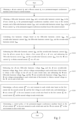
- FIG. 2 is a flowchart of steps of a permanent-magnet synchronous machine control method according to an embodiment of this application.
- the method is applied to the electric machine controller 10 in the permanent-magnet synchronous machine control system 100 shown in FIG. 1 . It needs to be noted that the permanent-magnet synchronous machine control method according to this embodiment of this application is not limited to the order shown in FIG. 2 or the order described below.
- the method includes steps S101 to S107.
- Step S101 Obtaining a d -axis current i d and a q -axis current i q in a permanent-magnet synchronous machine control loop at a current moment.
- the electric machine controller When the electric machine controller is directly connected to the permanent-magnet synchronous machine, the electric machine controller is configured to obtain a three-phase current in the permanent-magnet synchronous machine control loop at the current moment, and then perform current transformation based on a coordinate transformation algorithm to obtain the d -axis current i d and the q 1 -axis current i q in the permanent-magnet synchronous machine control loop at the current moment.
- the coordinate transformation algorithm is used to transform the three-phase current into the dq -axis current.
- Such coordinate transformation algorithm is well known in the art, and is not detailed in this application.
- the transformation process may be performed by a discrete control chip.
- a control chip is disposed in the permanent-magnet synchronous machine control system, and is connected between the electric machine controller and the permanent-magnet synchronous machine.
- the control chip is configured to obtain a three-phase current in the permanent-magnet synchronous machine control loop at the current moment, and then perform current transformation based on the coordinate transformation algorithm to obtain the d -axis current i d and the q -axis current i q in the permanent-magnet synchronous machine control loop at the current moment.
- control chip transmits the d -axis current i d and the q -axis current i q in the permanent-magnet synchronous machine control loop at the current moment to the electric machine controller, so that the electric machine controller obtains the d -axis current i d and the q -axis current i q in the permanent-magnet synchronous machine control loop at the current moment.
- Step S102 Obtaining a fifth-order harmonic current i d 5 th and a seventh-order harmonic current i d 7 th in the d -axis current i d in the permanent-magnet synchronous machine control loop at the current moment, and a fifth-order harmonic current i q 5 th and a seventh-order harmonic current i q 7 th in the q -axis current i q in the permanent-magnet synchronous machine loop at the current moment.
- Harmonic currents existent in the permanent-magnet synchronous machine are primarily the fifth-order harmonic current and the seventh-order harmonic current. Therefore, it is necessary to extract the fifth-order harmonic current i d 5 th and the seventh-order harmonic current i d 7 th in the d -axis current i d in the permanent-magnet synchronous machine control loop at the current moment and the fifth-order harmonic current i q 5 th and the seventh-order harmonic current i q 7 th in the q -axis current i q in the permanent-magnet synchronous machine loop at the current moment.
- this step includes: obtaining a three-phase current in the permanent-magnet synchronous machine control loop at the current moment; transforming the three-phase current into a d -axis current and a q -axis current in a fifth-order rotating coordinate system based on a coordinate transformation algorithm and a phase angle of a fifth-order harmonic; filtering the d -axis current and the q -axis current in the fifth-order rotating coordinate system by using a filter, so as to obtain the fifth-order harmonic current i d 5 th and the fifth-order harmonic current i q 5 th ; transforming the three-phase current into a d -axis current and a q -axis current in a seventh-order rotating coordinate system based on the coordinate transformation algorithm and a phase angle of a seventh-order harmonic; and filtering the d- axis current and the q -axis current in the seventh-order rotating coordinate system by using the filter, so as to obtain the seventh-order harmonic current i
- the harmonic currents extracted from the d axis and the q axis are a current in a fifth-order rotating coordinate system and a current in a seventh-order rotating coordinate system respectively.
- both the fifth-order harmonic current extracted from the d -axis current and the fifth-order harmonic current extracted from the q -axis current are currents in the fifth-order rotating coordinate system
- both the seventh-order harmonic current extracted from the d -axis current and the seventh-order harmonic current extracted from the q -axis current are currents in the seventh-order rotating coordinate system.
- the currents in the fifth-order rotating coordinate system and the seventh-order rotating coordinate system are uniformly transformed for use in a first-order synchronous rotating coordinate system identical with the d -axis current i d and the q -axis current i q , so as to obtain the fifth-order harmonic current i d 5 th , the fifth-order harmonic current i q 5 th , the seventh-order harmonic current i d 7 th , and the seventh-order harmonic current i q 7 th that are transformed for use in the first-order synchronous rotating coordinate system.
- the coordinate transformation may be Park transformation, which is well known in the art, and is not described in detail here.
- Step S103 Calculating four harmonic voltages based on the fifth-order harmonic current i d 5 th , the seventh-order harmonic current i d 7 th the fifth-order harmonic current i q 5 th , and the seventh-order harmonic current i q 7 th .
- the four harmonic voltages include a d -axis fifth-order harmonic voltage u d 5 th , a q -axis fifth-order harmonic voltage u q 5 th , a d -axis seventh-order harmonic voltage u d 7 th , and a q -axis seventh-order harmonic voltage u q 7 th .
- w e represents an electrical angular velocity
- R s represents a stator resistance
- L d represents a d -axis inductance parameter
- L q represents a q -axis inductance parameter
- Step S104 Subtracting the fifth-order harmonic current i d 5 th and the seventh-order harmonic current i d 7 th from the d -axis current i d to obtain a first current i d k on a d axis; and subtracting the fifth-order harmonic current i q 5 th and the seventh-order harmonic current i q 7 th from the q -axis current i q to obtain a second current i q k on a q axis.
- the d -axis current i d and the q -axis current i q each include harmonic components (fifth-order harmonic current and seventh-order harmonic current). Therefore, the harmonic components are removed to obtain a current net of the harmonic components.
- Step S105 Subtracting the d -axis fifth-order harmonic voltage u d 5 th and the d -axis seventh-order harmonic voltage u d 7 th from a d -axis voltage corresponding to each switch state of the inverter to obtain a first voltage on the d axis in each switch state; and subtracting the q -axis fifth-order harmonic voltage u q 5 th and the q -axis seventh-order harmonic voltage u q 7 th from a q -axis voltage corresponding to each switch state of the inverter to obtain a second voltage on the q axis in each switch state.
- u d k * represents the d -axis voltage in any switch state
- u d k represents the first voltage corresponding to u d k * . It needs to be noted that the first voltage on the d axis in each switch state can be obtained through formula (5).
- u q k * represents the q -axis voltage in any switch state
- u q k represents the second voltage corresponding to u q k * . It needs to be noted that the second voltage on the q axis in each switch state can be obtained through formula (6).
- Step S 106 Determining a d -axis current i d k + 1 at a next moment in each switch state based on the first current i d k , the second current i q k , and the first voltage in each switch state; and determining a q -axis current i q k + 1 at the next moment in each switch state based on the first current i d k , the second current i q k , and the second voltage in each switch state.
- the current at the next moment in each switch state is predicted based on the current net of the harmonic components at the current moment and the voltage net of the harmonic components in each switch state.
- i d k + 1 1 ⁇ R s T s L d i d k + w e L q T s L d i q k + T s L d u d k
- u d k represents the first voltage in any switch state.
- the first voltage has been pre-transformed into a voltage in a first-order synchronous rotating coordinate system.
- i d k + 1 represents the d -axis current at the next moment in a switch state corresponding to u d k .
- R s represents a stator resistance;
- L d represents a d -axis inductance parameter;
- T s represents sampling time;
- L q represents a q -axis inductance parameter;
- ⁇ f represents a flux linkage; and
- w e represents an electrical angular velocity.
- i q k + 1 ⁇ w e L d T s L q i d k + 1 ⁇ R s T s L d i q k + T s L d u q k ⁇ w e ⁇ ⁇ L q T s
- u q k represents the second voltage in any switch state.
- the second voltage has been pre-transformed into a voltage in a first-order synchronous rotating coordinate system.
- i q k + 1 represents the q -axis current at the next moment in a switch state corresponding to u q k .
- R s represents the stator resistance;
- L d represents the d -axis inductance parameter;
- T s represents sampling time;
- L q represents the q -axis inductance parameter;
- ⁇ f represents a flux linkage; and
- w e represents the electrical angular velocity.
- Step S107 Determining a control policy of the permanent-magnet synchronous machine based on the d -axis current i d k + 1 at the next moment in each switch state and the q -axis current i q k + 1 at the next moment in each switch state.
- the control policy of the permanent-magnet synchronous machine can be determined based on the prediction result.
- the foregoing step may specifically include: obtaining a d -axis reference current i d ref and a q -axis reference current i q ref based on an MTPA (maximum torque per ampere) and a torque current distribution policy of flux weakening control; and calculating a cost function corresponding to each switch state based on the d -axis current i d k + 1 at the next moment in each switch state, the q -axis current i q k + 1 at the next moment in each switch state, the d -axis reference current i d ref , and the q -axis reference current i q ref .
- a switch state with a lowest cost function is the control policy of the permanent-magnet synchronous machine.
- the MTPA and the torque current distribution policy of flux weakening control are control policies well known in the art, and therefore, are not described in detail in this application.
- the MTPA and the torque current distribution policy of flux weakening control are intended to provide reference currents (including the d -axis reference current i d ref and the q -axis reference current i q ref ) to facilitate calculation of the cost function.
- g represents a calculated value of the cost function
- i d k + 1 represents the d -axis current at the next moment in a switch state
- i q k + 1 represents the q -axis current at the next moment in said switch state.
- the cost function corresponding to each switch state can be obtained through formula (9), and then the switch state with a lowest calculated value of the cost function serves as the control policy of the permanent-magnet synchronous machine. That is, the permanent-magnet synchronous machine is controlled by using a switch corresponding to the switch state with the lowest calculated value of the cost function.
- the permanent-magnet synchronous machine control method adopts the idea of a finite set, calculates the cost function corresponding to each switch state based on a voltage vector of the switch state of the inverter, and determines an optimal switch state based on the cost function.
- a modem in vector control is eliminated, the control structure of the system is further simplified, and dynamic response of the system is improved by directly outputting an optimal switch vector.
- the inverter is a two-level inverter.
- the two-level inverter includes eight switch states, and the eight switch states correspond to seven voltage vectors.
- an optimal switch state can be determined from the eight switch states in the way above to control the permanent-magnet synchronous machine.
- the electric machine controller is configured to obtain a three-phase current (including i a , i b , and i c ) in the permanent-magnet synchronous machine control loop at the current moment, and then perform current transformation based on the coordinate transformation algorithm to obtain the d- axis current i d and the q -axis current i q in the permanent-magnet synchronous machine control loop at the current moment.
- Harmonic currents existent in the permanent-magnet synchronous machine are primarily the fifth-order harmonic current and the seventh-order harmonic current. Therefore, a harmonic current calculation module shown in FIG. 3 extracts the fifth-order harmonic current i d 5 th and the seventh-order harmonic current i d 7 th in the d -axis current i d in the permanent-magnet synchronous machine control loop at the current moment and the fifth-order harmonic current i q 5 th and the seventh-order harmonic current i q 7 th in the q -axis current i q in the permanent-magnet synchronous machine loop at the current moment.
- the three-phase current (including i a , i b , and i c ) into a d -axis current and a q -axis current in a fifth-order rotating coordinate system based on a coordinate transformation algorithm and a phase angle of a fifth-order harmonic; filtering the d -axis current and the q -axis current in the fifth-order rotating coordinate system by using a filter, so as to obtain the fifth-order harmonic current i d 5 th and the fifth-order harmonic current i q 5 th ; transforming the three-phase current into a d -axis current and a q -axis current in a seventh-order rotating coordinate system based on the coordinate transformation algorithm and a phase angle of a seventh-order harmonic; and filtering the d -axis current and the q -axis current in the seventh-order rotating coordinate system by using the filter, so as to obtain the seventh-order harmonic current i d 7 th and the
- a harmonic voltage calculation module shown in FIG. 3 calculates the d -axis fifth-order harmonic voltage u d 5 th , the q -axis fifth-order harmonic voltage u q 5 th , the d -axis seventh-order harmonic voltage u d 7 th , and the q -axis seventh-order harmonic voltage u q 7 th .
- the fifth-order harmonic current i d 5 th and the seventh-order harmonic current i d 7 th are subtracted from the d -axis current i d to obtain a first current i d k on a d axis.
- the fifth-order harmonic current i q 5 th and the seventh-order harmonic current i q 7 th are subtracted from the q axis current i q to obtain a second current i q k on a q axis.
- the d -axis fifth-order harmonic voltage u d 5 th and the d -axis seventh-order harmonic voltage u d 7 th are subtracted from a d -axis voltage corresponding to each switch state of the inverter to obtain a first voltage on the d axis in each switch state.
- the q -axis fifth-order harmonic voltage u q 5 th and the q -axis seventh-order harmonic voltage u q 7 th are subtracted from a q -axis voltage corresponding to each switch state of the inverter to obtain a second voltage on the q axis in each switch state.
- a d -axis current i d k + 1 at the next moment in each switch state is determined based on the first current i d k and the first voltage in each switch state; and a q -axis current i q k + 1 at the next moment in each switch state is determined based on the second current i q k and the second voltage in each switch state.
- a d -axis reference current i d ref and a q -axis reference current i q ref are obtained based on an MTPA and a torque current distribution policy of flux weakening control.
- a cost function g i d k + 1 ⁇ i d ref 2 + i q k + 1 ⁇ i q ref 2 corresponding to each switch state is calculated based on the d- axis current i d k + 1 at the next moment in each switch state, the q -axis current i q k + 1 at the next moment in each switch state, the d -axis reference current i d ref , and the q -axis reference current i q ref .
- the inverter shown in FIG. 3 is a two-level inverter.
- the two-level inverter includes eight switch states, and the eight switch states correspond to seven voltage vectors. Because two of the voltage vectors are the same, the vector diagram shown in FIG. 3 just includes six vectors.
- the relevant structures of the MTPA and the torque current distribution policy of flux weakening control are structures well known in the art, and therefore, are not described in detail in this application.
- the permanent-magnet synchronous machine control method predicts the corresponding -axis current and -axis current at the next moment in each switch state based on the -axis current and the -axis current net of the harmonic components at the current moment, and then determines the control policy of the permanent-magnet synchronous machine based on the prediction result.
- the technical solution in this application cancels the existing PI controllers by using the model predictive control algorithm instead, avoids complicated PI parameter adjustment, simplifies the system structure, and is more effective in suppressing the harmonic current.
- an embodiment of this application further provides a permanent-magnet synchronous machine control device 200, including: a first obtaining module 201, a second obtaining module 202, a first calculation module 203, a second calculation module 204, a third calculation module 205, a fourth calculation module 206, and a determining module 207.
- the first obtaining module 201 is configured to obtain a d -axis current i d and a q -axis 1 current i q in a permanent-magnet synchronous machine control loop at a current moment.
- the second obtaining module 202 is configured to obtain a fifth-order harmonic current i d 5 th and a seventh-order harmonic current i d 7 th in the d -axis current i d in the permanent-magnet synchronous machine control loop at the current moment and a fifth-order harmonic current i q 5 th and a seventh-order harmonic current i q 7 th in the q -axis current i q in the permanent-magnet synchronous machine loop at the current moment.
- the first calculation module 203 is configured to calculate four harmonic voltages based on the fifth-order harmonic current i d 5 th , the seventh-order harmonic current i d 7 th , the fifth-order harmonic current i q 5 th , and the seventh-order harmonic current i q 7 th , where the four harmonic voltages include a d -axis fifth-order harmonic voltage u d 5 th , a q -axis fifth-order harmonic voltage u q 5 th , a d- axis seventh-order harmonic voltage u d 7 th , and a q -axis seventh-order harmonic voltage u q 7 th .
- the second calculation module 204 is configured to subtract the fifth-order harmonic current i d 5 th and the seventh-order harmonic current u d 7 th from the d -axis current i d to obtain a first current i d k on a d axis, and subtract the fifth-order harmonic current i q 5 th and the seventh-order harmonic current i q 7 th from the q -axis current i q to obtain a second current i q k on a q axis.
- the third calculation module 205 is configured to subtract the d -axis fifth-order harmonic voltage u d 5 th and the d -axis seventh-order harmonic voltage u d 7 th from a d -axis voltage corresponding to each switch state of the inverter to obtain a first voltage on the d axis in each switch state; and subtract the q -axis fifth-order harmonic voltage u q 5 th and the q -axis seventh-order harmonic voltage u q 7 th from a q -axis voltage corresponding to each switch state of the inverter to obtain a second voltage on the q axis in each switch state.
- the fourth calculation module 206 is configured to determine a d -axis current i d k + 1 at a next moment in each switch state based on the first current i d k , the second current i q k , and the first voltage in each switch state; and determine a q -axis current i q k + 1 at the next moment in each switch state based on the first current i d k , the second current i q k , and the second voltage in each switch state; and
- the determining module 207 is configured to determine a control policy of the permanent-magnet synchronous machine based on the d -axis current i d k + 1 at the next moment in each switch state and the q -axis current i q k + 1 at the next moment in each switch state.
- the second obtaining module is specifically configured to obtain a three-phase current in the permanent-magnet synchronous machine control loop at the current moment; transform the three-phase current into a d -axis current and a q -axis current in a fifth-order rotating coordinate system based on a coordinate transformation algorithm and a phase angle of a fifth-order harmonic; filter the d -axis current and the q -axis current in the fifth-order rotating coordinate system by using a filter, so as to obtain the fifth-order harmonic current i d 5 th and the fifth-order harmonic current i q 5 th ; transform the three-phase current into a d -axis current and a q -axis current in a seventh-order rotating coordinate system based on the coordinate transformation algorithm and a phase angle of a seventh-order harmonic; and filter the d -axis current and the q -axis current in the seventh-order rotating coordinate system by using the filter, so as to obtain the seventh-order harmonic current i
- the determining module is specifically configured to obtain a d -axis reference current i d ref and a q -axis reference current i q ref based on an MTPA and a torque current distribution policy of flux weakening control; and calculate a cost function corresponding to each switch state based on the d -axis current i d k + 1 at the next moment in each switch state, the q -axis current i q k + 1 at the next moment in each switch state, the d -axis reference current i d ref , and the q -axis reference current i q ref .
- a switch state with a lowest cost function is the control policy of the permanent-magnet synchronous machine.
- an embodiment of this application further provides a computer-readable storage medium on which a computer program is stored. When executed, the computer program performs the method provided in the foregoing embodiment.
- the storage medium may be any available medium accessible to a computer, or a data storage device such as a server or data center that integrates one or more available media.
- the available media may be a magnetic medium (such as a floppy disk, a hard disk, or a magnetic tape), an optical medium (such as a DVD), or a semiconductor medium (such as a solid state disk (SSD)).
- the disclosed device and method may be implemented by other means.
- the device embodiment described above is merely exemplary.
- the unit division is merely division with respect to logical functions, and in actual implementations, the units may be divided in other manners.
- a plurality of units or components may be combined or integrated into another system, or some features may be ignored or not implemented.
- the displayed or discussed mutual couplings or direct couplings or communications connections may be implemented through some communications interfaces.
- the indirect couplings or communications connections between the devices or units may be implemented in electronic, mechanical or other forms.
- the units described as discrete components above may be separated physically or not; and the components illustrated as units may be physical units or not, that is, they may be located in one place or distributed on a plurality of network elements. Some or all of the units may be selected according to actual needs to achieve the objectives of the solutions of the embodiments.
- function modules in each embodiment of this application may be integrated together to form a stand-alone part, or each module may exist alone, or two or more modules may be integrated into a stand-alone part.
Landscapes
- Engineering & Computer Science (AREA)
- Power Engineering (AREA)
- Control Of Ac Motors In General (AREA)
Abstract
Description
- This application relates to the technical field of electric machine control, and in particular, to a permanent-magnet synchronous machine control method and device, and a permanent-magnet synchronous machine control system.
- As a high-performance drive motor or generator, permanent-magnet synchronous machines are widely used in the fields such as new-energy electric vehicles, wind power generation, and ship turbine propulsion currently. A built-in permanent-magnet synchronous machine, which can effectively utilize a reluctance torque more easily by virtue of a salient pole structure, is more suitable for use in an electric vehicle currently.
- However, torque ripples always exist in a control process of the permanent-magnet synchronous machine (such as a built-in permanent-magnet synchronous machine), and drastically affect the use of the electric machine on an occasion that requires high-precision control. Reasons for the occurrence of the torque ripples partly lie in a harmonic torque brought by a dead time and a non-linear characteristic of an inverter. With such harmonic components being mixed with fundamental current components, the permanent-magnet synchronous machine incurs greater iron loss and copper loss, thereby drastically affecting normal drive control efficiency, and also increasing the possibility of current overshoot and runaway and bringing safety hazards. This bottlenecks the application scope of the permanent-magnet synchronous machine.
- In order to eliminate the harmonic torque, harmonic current components during the operation of the electric machine need to be extracted first. However, the harmonic current suppression method currently available needs participation of a large number of PI (Proportional Integral, proportional integral) controllers, and the entire suppression process involves complicated PI parameter adjustment. Because a large number of PI controllers are integrated, the complexity of the entire control system is relatively high.
- An objective of embodiments of this application is to provide a permanent-magnet synchronous machine control method and device, and a permanent-magnet synchronous machine control system to simplify the complexity of the control system and avoid a complicated parameter adjustment process brought by a large number of PI controllers.
- This application is implemented in the following way:
According to a first aspect, an embodiment of this application provides a permanent-magnet synchronous machine control method, including: obtaining a d-axis current id and a q-axis current iq in a permanent-magnet synchronous machine control loop at a current moment; obtaining a fifth-order harmonic current i d5th and a seventh-order harmonic current i d7th in the d-axis current id in the permanent-magnet synchronous machine control loop at the current moment, and a fifth-order harmonic current i q5th and a seventh-order harmonic current i q7th in the q-axis current iq in the permanent-magnet synchronous machine loop at the current moment; calculating four harmonic voltages based on the fifth-order harmonic current i d5th , the seventh-order harmonic current i d7th , the fifth-order harmonic current i q5th , and the seventh-order harmonic current i q7th , where the four harmonic voltages include a d-axis fifth-order harmonic voltage u d5th , a q-axis fifth-order harmonic voltage u q5th , a d-axis seventh-order harmonic voltage u d7th , and a q-axis seventh-order harmonic voltage u q7th ; subtracting the fifth-order harmonic current i d5th and the seventh-order harmonic current i d7th from the d-axis current id to obtain a first current


- Based on a model predictive control algorithm, the permanent-magnet synchronous machine control method according to this embodiment of this application predicts the corresponding d-axis current and q-axis current at the next moment in each switch state with reference to the d-axis current and q-axis current net of the harmonic components at the current moment, and then determines the control policy of the permanent-magnet synchronous machine based on the prediction result. Compared with the existing harmonic current suppression method, the technical solution in this application cancels the existing PI controllers by using the model predictive control algorithm instead, avoids complicated PI parameter adjustment, simplifies the system structure, and is more effective in suppressing the harmonic current.
- With reference to the technical solution according to the first aspect, in some possible implementations, the obtaining a fifth-order harmonic current i d5th and a seventh-order harmonic current i d7th in the d-axis current id in the permanent-magnet synchronous machine control loop at the current moment, and a fifth-order harmonic current i q5th and a seventh-order harmonic current i q7th in the q-axis current iq in the permanent-magnet synchronous machine loop at the current moment includes: obtaining a three-phase current in the permanent-magnet synchronous machine control loop at the current moment; transforming the three-phase current into a d-axis current and a q-axis current in a fifth-order rotating coordinate system based on a coordinate transformation algorithm and a phase angle of a fifth-order harmonic; filtering the d-axis current and the q-axis current in the fifth-order rotating coordinate system by using a filter, so as to obtain the fifth-order harmonic current i d5th and the fifth-order harmonic current i q5th ; transforming the three-phase current into a d-axis current and a q-axis current in a seventh-order rotating coordinate system based on the coordinate transformation algorithm and a phase angle of a seventh-order harmonic; and filtering the d-axis current and the q-axis current in the seventh-order rotating coordinate system by using the filter, so as to obtain the seventh-order harmonic current i d7th and the seventh-order harmonic current i q7th .
- With reference to the technical solution according to the first aspect, in some possible implementations, a formula for calculating the d-axis fifth-order harmonic voltage u d5th is: u d5th = 5w e Lqi q5th + Rsi d5th ; a formula for calculating the q-axis fifth-order harmonic voltage u q5th is: u q5th = -5w e Ldi d5th + Rsi q5th ; a formula for calculating the d-axis seventh-order harmonic voltage u d7th is: u d7th = -7weLqi q7th + Rsi d7th ; and a formula for calculating the q-axis seventh-order harmonic voltage uq7th is: u q7th = 7weLdi d7th + Rsi q7th , where, we represents an electrical angular velocity, Rs represents a stator resistance, Ld represents a d-axis inductance parameter, and Lq represents a q-axis inductance parameter.
- With reference to the technical solution according to the first aspect, in some possible implementations, the determining a control policy of the permanent-magnet synchronous machine based on the d-axis current


- The permanent-magnet synchronous machine control method according to this embodiment of this application adopts the idea of a finite set, calculates the cost function corresponding to each switch state based on a voltage vector of the switch state of the inverter, and determines an optimal switch state based on the cost function. In this way, a modem in vector control is eliminated, the control structure of the system is further simplified, and dynamic response of the system is improved by directly outputting an optimal switch vector.
- With reference to the technical solution according to the first aspect, in some possible implementations, the inverter is a two-level inverter, and the two-level inverter includes eight switch states.
- According to a second aspect, an embodiment of this application provides a permanent-magnet synchronous machine control device, including: a first obtaining module, configured to obtain a d-axis current id and a q-axis current iq in a permanent-magnet synchronous machine control loop at a current moment; a second obtaining module, configured to obtain a fifth-order harmonic current i d5th and a seventh-order harmonic current i d7th in the d-axis current id in the permanent-magnet synchronous machine control loop at the current moment, and a fifth-order harmonic current i q5th and a seventh-order harmonic current i q7th in the q-axis current iq in the permanent-magnet synchronous machine loop at the current moment; a first calculation module, configured to calculate four harmonic voltages based on the fifth-order harmonic current i d5th , the seventh-order harmonic current i d7th , the fifth-order harmonic current i q5th , and the seventh-order harmonic current i q7th , where the four harmonic voltages include a d-axis fifth-order harmonic voltage u d5 th, a q-axis fifth-order harmonic voltage u q5th , a d-axis seventh-order harmonic voltage u d7th , and a q-axis seventh-order harmonic voltage u q7th ; a second calculation module, configured to subtract the fifth-order harmonic current i d5th and the seventh-order harmonic current i d7th from the d-axis current id to obtain a first current


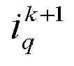
- With reference to the technical solution according to the second aspect, in some possible implementations, the second obtaining module is specifically configured to obtain a three-phase current in the permanent-magnet synchronous machine control loop at the current moment; transform the three-phase current into a d-axis current and a q-axis current in a fifth-order rotating coordinate system based on a coordinate transformation algorithm and a phase angle of a fifth-order harmonic; filter the d-axis current and the q-axis current in the fifth-order rotating coordinate system by using a filter, so as to obtain the fifth-order harmonic current i d5th and the fifth-order harmonic current i q5th ; transform the three-phase current into a d-axis current and a q-axis current in a seventh-order rotating coordinate system based on the coordinate transformation algorithm and a phase angle of a seventh-order harmonic; and filter the d-axis current and the q-axis current in the seventh-order rotating coordinate system by using the filter, so as to obtain the seventh-order harmonic current i d7th and the seventh-order harmonic current i q7th .
- With reference to the technical solution according to the second aspect, in some possible implementations, a formula for calculating the d-axis fifth-order harmonic voltage u d5th is: u d5th = 5weLqiq5th + Rsi d5th ; a formula for calculating the q-axis fifth-order harmonic voltage u q5th is: u q5th = -5weLdi d5th + Rsi q5th ; a formula for calculating the d-axis seventh-order harmonic voltage u d7th is: u d7th = -7weLqi q7th + Rsi d7th ; and a formula for calculating the q-axis seventh-order harmonic voltage u q7th is: u q7th = 7weLdi d7th + Rsi q7th , where, we represents an electrical angular velocity, Rs represents a stator resistance, Ld represents a d-axis inductance parameter, and Lq represents a q-axis inductance parameter.
- With reference to the technical solution according to the second aspect, in some possible implementations, the determining module is specifically configured to obtain a d-axis reference current


- According to a third aspect, an embodiment of this application provides a permanent-magnet synchronous machine control system, including: an electric machine controller, a permanent-magnet synchronous machine, and an inverter. The electric machine controller is connected to the permanent-magnet synchronous machine and the inverter separately. The permanent-magnet synchronous machine is further connected to the inverter. The electric machine controller is configured to perform the method according to the embodiment of the first aspect and/or with reference to some possible implementations of the embodiment of the first aspect.
- According to a fourth aspect, an embodiment of this application provides a computer-readable storage medium on which a computer program is stored. When executed by a processor, the computer program implements the method according to the embodiment of the first aspect and/or with reference to some possible implementations of the embodiment of the first aspect.
- To describe technical solutions in embodiments of this application more clearly, the following outlines the drawings to be used in the embodiments of this application. Understandably, the following drawings show merely some embodiments of this application, and therefore, are not intended to limit the scope. A person of ordinary skill in the art may derive other related drawings from the drawings without making any creative efforts.
-
FIG. 1 is a modular block diagram of a permanent-magnet synchronous machine control system according to an embodiment of this application; -
FIG. 2 is a flowchart of steps of a permanent-magnet synchronous machine control method according to an embodiment of this application; -
FIG. 3 is a control block diagram of a permanent-magnet synchronous machine control system according to an embodiment of this application; and -
FIG. 4 is a modular block diagram of a permanent-magnet synchronous machine control device according to an embodiment of this application. - Reference numerals: 100-permanent-magnet synchronous machine control system; 10-electric machine controller; 20-permanent-magnet synchronous machine; 30-inverter; 200-permanent-magnet synchronous machine control device; 201-first obtaining module; 202-second obtaining module; 203-first calculation module; 204-second calculation module; 205-third calculation module; 206-fourth calculation module; and 207-determining module.
- The following describes technical solutions in embodiments of this application with reference to the drawings in the embodiments of this application.
- Referring to
FIG 1 , an embodiment of this application provides a permanent-magnet synchronous machine control system 100, including: anelectric machine controller 10, a permanent-magnet synchronous machine 20, and aninverter 30. - The
electric machine controller 10 is connected to the permanent-magnet synchronous machine 20 and theinverter 30 separately. The permanent-magnet synchronous electric machine 20 is further connected to theinverter 30. - It needs to be noted that the
inverter 30 is a transformer that transforms direct-current electrical energy into a constant-frequency constant-voltage or frequency-regulated voltage-regulated alternating current. Theelectric machine controller 10 may be an integrated circuit chip capable of signal processing. Alternatively, theelectric machine controller 10 may be a general-purpose processor, and may be, for example, a digital signal processor (digital signal processor, DSP), an application specific integrated circuit (application specific integrated circuit, ASIC), a discrete gate or a transistor logic device, or a discrete hardware component, and can implement or perform the methods, steps, and logical block diagrams disclosed in the embodiments of this application. In addition, the general-purpose processor may be a microprocessor, or any conventional processor or the like. - In this embodiment of this application, the
electric machine controller 10 controls the permanent-magnet synchronous machine 20 by controlling theinverter 30. - Referring to
FIG. 2, FIG. 2 is a flowchart of steps of a permanent-magnet synchronous machine control method according to an embodiment of this application. The method is applied to theelectric machine controller 10 in the permanent-magnet synchronous machine control system 100 shown inFIG. 1 . It needs to be noted that the permanent-magnet synchronous machine control method according to this embodiment of this application is not limited to the order shown inFIG. 2 or the order described below. The method includes steps S101 to S107. - Step S101: Obtaining a d-axis current id and a q-axis current iq in a permanent-magnet synchronous machine control loop at a current moment.
- When the electric machine controller is directly connected to the permanent-magnet synchronous machine, the electric machine controller is configured to obtain a three-phase current in the permanent-magnet synchronous machine control loop at the current moment, and then perform current transformation based on a coordinate transformation algorithm to obtain the d-axis current id and the q 1 -axis current iq in the permanent-magnet synchronous machine control loop at the current moment.
- The coordinate transformation algorithm is used to transform the three-phase current into the dq-axis current. Such coordinate transformation algorithm is well known in the art, and is not detailed in this application.
- In addition, the transformation process may be performed by a discrete control chip. For example, a control chip is disposed in the permanent-magnet synchronous machine control system, and is connected between the electric machine controller and the permanent-magnet synchronous machine. The control chip is configured to obtain a three-phase current in the permanent-magnet synchronous machine control loop at the current moment, and then perform current transformation based on the coordinate transformation algorithm to obtain the d-axis current id and the q-axis current iq in the permanent-magnet synchronous machine control loop at the current moment. Then the control chip transmits the d-axis current id and the q-axis current iq in the permanent-magnet synchronous machine control loop at the current moment to the electric machine controller, so that the electric machine controller obtains the d-axis current id and the q-axis current iq in the permanent-magnet synchronous machine control loop at the current moment.
- Step S102: Obtaining a fifth-order harmonic current i d5th and a seventh-order harmonic current i d7th in the d-axis current id in the permanent-magnet synchronous machine control loop at the current moment, and a fifth-order harmonic current i q5th and a seventh-order harmonic current i q7th in the q-axis current iq in the permanent-magnet synchronous machine loop at the current moment.
- Harmonic currents existent in the permanent-magnet synchronous machine are primarily the fifth-order harmonic current and the seventh-order harmonic current. Therefore, it is necessary to extract the fifth-order harmonic current i d5th and the seventh-order harmonic current i d7th in the d-axis current id in the permanent-magnet synchronous machine control loop at the current moment and the fifth-order harmonic current i q5th and the seventh-order harmonic current i q7th in the q-axis current iq in the permanent-magnet synchronous machine loop at the current moment.
- Specifically, this step includes: obtaining a three-phase current in the permanent-magnet synchronous machine control loop at the current moment; transforming the three-phase current into a d -axis current and a q-axis current in a fifth-order rotating coordinate system based on a coordinate transformation algorithm and a phase angle of a fifth-order harmonic; filtering the d-axis current and the q-axis current in the fifth-order rotating coordinate system by using a filter, so as to obtain the fifth-order harmonic current i d5th and the fifth-order harmonic current i q5th ; transforming the three-phase current into a d-axis current and a q-axis current in a seventh-order rotating coordinate system based on the coordinate transformation algorithm and a phase angle of a seventh-order harmonic; and filtering the d-axis current and the q-axis current in the seventh-order rotating coordinate system by using the filter, so as to obtain the seventh-order harmonic current i d7th and the seventh-order harmonic current i q7th .
- It needs to be noted that the harmonic currents extracted from the d axis and the q axis are a current in a fifth-order rotating coordinate system and a current in a seventh-order rotating coordinate system respectively. For example, both the fifth-order harmonic current extracted from the d -axis current and the fifth-order harmonic current extracted from the q-axis current are currents in the fifth-order rotating coordinate system, and both the seventh-order harmonic current extracted from the d-axis current and the seventh-order harmonic current extracted from the q-axis current are currents in the seventh-order rotating coordinate system. To facilitate unified calculation, the currents in the fifth-order rotating coordinate system and the seventh-order rotating coordinate system are uniformly transformed for use in a first-order synchronous rotating coordinate system identical with the d-axis current id and the q-axis current iq , so as to obtain the fifth-order harmonic current i d5th , the fifth-order harmonic current i q5th , the seventh-order harmonic current i d7th , and the seventh-order harmonic current i q7th that are transformed for use in the first-order synchronous rotating coordinate system.
- The coordinate transformation may be Park transformation, which is well known in the art, and is not described in detail here.
- Step S103: Calculating four harmonic voltages based on the fifth-order harmonic current i d5th , the seventh-order harmonic current i d7th the fifth-order harmonic current i q5th , and the seventh-order harmonic current i q7th .
- The four harmonic voltages include a d-axis fifth-order harmonic voltage u d5 th, a q-axis fifth-order harmonic voltage u q5th , a d-axis seventh-order harmonic voltage u d7th , and a q-axis seventh-order harmonic voltage u q7 th.
- A formula for calculating the d-axis fifth-order harmonic voltage u d5th is:

- A formula for calculating the q-axis fifth-order harmonic voltage u q5th is:

- A formula for calculating the d-axis seventh-order harmonic voltage u d7th is:

- A formula for calculating the q-axis seventh-order harmonic voltage u q7th is:

- In formulas (1) to (4), we represents an electrical angular velocity, Rs represents a stator resistance, Ld represents a d-axis inductance parameter, and Lq represents a q-axis inductance parameter.
- Step S104: Subtracting the fifth-order harmonic current i d5th and the seventh-order harmonic current i d7th from the d-axis current id to obtain a first current


- The d-axis current id and the q-axis current iq each include harmonic components (fifth-order harmonic current and seventh-order harmonic current). Therefore, the harmonic components are removed to obtain a current net of the harmonic components.
- Step S105: Subtracting the d-axis fifth-order harmonic voltage u d5th and the d-axis seventh-order harmonic voltage u d7th from a d-axis voltage corresponding to each switch state of the inverter to obtain a first voltage on the d axis in each switch state; and subtracting the q-axis fifth-order harmonic voltage u q5th and the q-axis seventh-order harmonic voltage u q7th from a q-axis voltage corresponding to each switch state of the inverter to obtain a second voltage on the q axis in each switch state.
- The expression for the first voltage is:

- In formula (5),


- The expression for the second voltage is:

- In formula (6),


- Step S 106: Determining a d-axis current


- In this embodiment of this application, the current at the next moment in each switch state is predicted based on the current net of the harmonic components at the current moment and the voltage net of the harmonic components in each switch state.
- The expression for the d-axis current


- In formula (7),


- The expression for the q-axis current


- In formula (8),


- Step S107: Determining a control policy of the permanent-magnet synchronous machine based on the d-axis current


- After the d-axis current
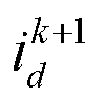

- The foregoing step may specifically include: obtaining a d-axis reference current


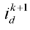


- It needs to be noted that the MTPA and the torque current distribution policy of flux weakening control are control policies well known in the art, and therefore, are not described in detail in this application. In this embodiment of this application, the MTPA and the torque current distribution policy of flux weakening control are intended to provide reference currents (including the d-axis reference current


- In an implementation, the expression for the cost function is:

- In formula (9), g represents a calculated value of the cost function,
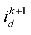

- The cost function corresponding to each switch state can be obtained through formula (9), and then the switch state with a lowest calculated value of the cost function serves as the control policy of the permanent-magnet synchronous machine. That is, the permanent-magnet synchronous machine is controlled by using a switch corresponding to the switch state with the lowest calculated value of the cost function.
- Evidently, the permanent-magnet synchronous machine control method according to this embodiment of this application adopts the idea of a finite set, calculates the cost function corresponding to each switch state based on a voltage vector of the switch state of the inverter, and determines an optimal switch state based on the cost function. In this way, a modem in vector control is eliminated, the control structure of the system is further simplified, and dynamic response of the system is improved by directly outputting an optimal switch vector.
- In this embodiment of this application, the inverter is a two-level inverter. The two-level inverter includes eight switch states, and the eight switch states correspond to seven voltage vectors.
- When the inverter is a two-level inverter, an optimal switch state can be determined from the eight switch states in the way above to control the permanent-magnet synchronous machine.
- For ease of understanding this solution, the permanent-magnet synchronous machine control method is described below with reference to a control block diagram of a permanent-magnet synchronous machine control system shown in
FIG. 3 . - First, the electric machine controller is configured to obtain a three-phase current (including ia , ib , and ic ) in the permanent-magnet synchronous machine control loop at the current moment, and then perform current transformation based on the coordinate transformation algorithm to obtain the d-axis current id and the q-axis current iq in the permanent-magnet synchronous machine control loop at the current moment.
- Harmonic currents existent in the permanent-magnet synchronous machine are primarily the fifth-order harmonic current and the seventh-order harmonic current. Therefore, a harmonic current calculation module shown in
FIG. 3 extracts the fifth-order harmonic current i d5th and the seventh-order harmonic current i d7th in the d-axis current id in the permanent-magnet synchronous machine control loop at the current moment and the fifth-order harmonic current i q5th and the seventh-order harmonic current i q7th in the q-axis current iq in the permanent-magnet synchronous machine loop at the current moment. The harmonic current extraction steps shown inFIG. 3 include: transforming the three-phase current (including ia, ib, and i c) into a d-axis current and a q-axis current in a fifth-order rotating coordinate system based on a coordinate transformation algorithm and a phase angle of a fifth-order harmonic; filtering the d-axis current and the q-axis current in the fifth-order rotating coordinate system by using a filter, so as to obtain the fifth-order harmonic current i d5th and the fifth-order harmonic current i q5th ; transforming the three-phase current into a d-axis current and a q-axis current in a seventh-order rotating coordinate system based on the coordinate transformation algorithm and a phase angle of a seventh-order harmonic; and filtering the d-axis current and the q-axis current in the seventh-order rotating coordinate system by using the filter, so as to obtain the seventh-order harmonic current i d7th and the seventh-order harmonic current i q7th . In the drawing, θr represents the phase angle. The phase angle of the fifth-order harmonic θr is -5θ , and the phase angle θr of the seventh-order harmonic is 7θ. - Then a harmonic voltage calculation module shown in
FIG. 3 calculates the d-axis fifth-order harmonic voltage u d5 th, the q-axis fifth-order harmonic voltage u q5th , the d-axis seventh-order harmonic voltage u d7th , and the q-axis seventh-order harmonic voltage u q7th . - Subsequently, the fifth-order harmonic current i d5th and the seventh-order harmonic current i d7th are subtracted from the d-axis current id to obtain a first current


- Finally, a d-axis reference current


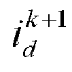


FIG. 3 is a two-level inverter. The two-level inverter includes eight switch states, and the eight switch states correspond to seven voltage vectors. Because two of the voltage vectors are the same, the vector diagram shown inFIG. 3 just includes six vectors. The relevant structures of the MTPA and the torque current distribution policy of flux weakening control are structures well known in the art, and therefore, are not described in detail in this application. - In conclusion, based on a model predictive control algorithm, the permanent-magnet synchronous machine control method according to this embodiment of this application predicts the corresponding -axis current and -axis current at the next moment in each switch state based on the -axis current and the -axis current net of the harmonic components at the current moment, and then determines the control policy of the permanent-magnet synchronous machine based on the prediction result. Compared with the existing harmonic current suppression method, the technical solution in this application cancels the existing PI controllers by using the model predictive control algorithm instead, avoids complicated PI parameter adjustment, simplifies the system structure, and is more effective in suppressing the harmonic current.
- Referring to
FIG. 4 , based on the same inventive conception, an embodiment of this application further provides a permanent-magnet synchronous machine control device 200, including: a first obtainingmodule 201, a second obtainingmodule 202, afirst calculation module 203, asecond calculation module 204, athird calculation module 205, afourth calculation module 206, and a determiningmodule 207. - The first obtaining
module 201 is configured to obtain a d-axis current id and a q-axis 1 current iq in a permanent-magnet synchronous machine control loop at a current moment. - The second obtaining
module 202 is configured to obtain a fifth-order harmonic current i d5th and a seventh-order harmonic current i d7th in the d-axis current id in the permanent-magnet synchronous machine control loop at the current moment and a fifth-order harmonic current i q5th and a seventh-order harmonic current i q7th in the q-axis current iq in the permanent-magnet synchronous machine loop at the current moment. - The
first calculation module 203 is configured to calculate four harmonic voltages based on the fifth-order harmonic current i d5th , the seventh-order harmonic current i d7th , the fifth-order harmonic current i q5th , and the seventh-order harmonic current i q7th , where the four harmonic voltages include a d-axis fifth-order harmonic voltage u d5 th, a q-axis fifth-order harmonic voltage u q5th , a d-axis seventh-order harmonic voltage u d7th , and a q-axis seventh-order harmonic voltage u q7th . - The
second calculation module 204 is configured to subtract the fifth-order harmonic current i d5th and the seventh-order harmonic current u d7th from the d-axis current id to obtain a first current

- The
third calculation module 205 is configured to subtract the d-axis fifth-order harmonic voltage u d5th and the d-axis seventh-order harmonic voltage u d7th from a d-axis voltage corresponding to each switch state of the inverter to obtain a first voltage on the d axis in each switch state; and subtract the q-axis fifth-order harmonic voltage u q5th and the q-axis seventh-order harmonic voltage u q7th from a q-axis voltage corresponding to each switch state of the inverter to obtain a second voltage on the q axis in each switch state. - The
fourth calculation module 206 is configured to determine a d-axis current


- The determining
module 207 is configured to determine a control policy of the permanent-magnet synchronous machine based on the d-axis current

- Optionally, the second obtaining module is specifically configured to obtain a three-phase current in the permanent-magnet synchronous machine control loop at the current moment; transform the three-phase current into a d-axis current and a q-axis current in a fifth-order rotating coordinate system based on a coordinate transformation algorithm and a phase angle of a fifth-order harmonic; filter the d -axis current and the q-axis current in the fifth-order rotating coordinate system by using a filter, so as to obtain the fifth-order harmonic current i d5th and the fifth-order harmonic current i q5th ; transform the three-phase current into a d-axis current and a q-axis current in a seventh-order rotating coordinate system based on the coordinate transformation algorithm and a phase angle of a seventh-order harmonic; and filter the d-axis current and the q-axis current in the seventh-order rotating coordinate system by using the filter, so as to obtain the seventh-order harmonic current i d7th and the seventh-order harmonic current i q7th .
- Optionally, a formula for calculating the d-axis fifth-order harmonic voltage u d5th is: u d5th = 5w e Lqi q5th + Rsi d5th ; a formula for calculating the q-axis fifth-order harmonic voltage u q5th is: u q5th = -5w e L d i d5th + Rsi q5th ; a formula for calculating the d-axis seventh-order harmonic voltage u d7th is: u d7th = -7weLqi q7th + Rsi d7th ; and a formula for calculating the q-axis seventh-order harmonic voltage u q7th is: u q7th = 7weLdi d7th + Rsi q7th , where, we represents an electrical angular velocity, Rs represents a stator resistance, Ld represents a d-axis inductance parameter, and Lq represents a q-axis inductance parameter.
- Optionally, the determining module is specifically configured to obtain a d-axis reference current


- It needs to be noted that, it can be clearly understood by a person skilled in the art that for ease and brevity of description, a specific working process of the foregoing system, device, and units can be obtained by referring to a corresponding process in the preceding method embodiment, and the details are omitted here.
- Based on the same inventive conception, an embodiment of this application further provides a computer-readable storage medium on which a computer program is stored. When executed, the computer program performs the method provided in the foregoing embodiment.
- The storage medium may be any available medium accessible to a computer, or a data storage device such as a server or data center that integrates one or more available media. The available media may be a magnetic medium (such as a floppy disk, a hard disk, or a magnetic tape), an optical medium (such as a DVD), or a semiconductor medium (such as a solid state disk (SSD)).
- In the embodiments provided in this application, it is understandable that the disclosed device and method may be implemented by other means. The device embodiment described above is merely exemplary. For example, the unit division is merely division with respect to logical functions, and in actual implementations, the units may be divided in other manners. For another example, a plurality of units or components may be combined or integrated into another system, or some features may be ignored or not implemented. In addition, the displayed or discussed mutual couplings or direct couplings or communications connections may be implemented through some communications interfaces. The indirect couplings or communications connections between the devices or units may be implemented in electronic, mechanical or other forms.
- In addition, the units described as discrete components above may be separated physically or not; and the components illustrated as units may be physical units or not, that is, they may be located in one place or distributed on a plurality of network elements. Some or all of the units may be selected according to actual needs to achieve the objectives of the solutions of the embodiments.
- In addition, function modules in each embodiment of this application may be integrated together to form a stand-alone part, or each module may exist alone, or two or more modules may be integrated into a stand-alone part.
- The relational terms herein such as first and second are used merely to differentiate one entity or operation from another, and do not necessarily require or imply any actual relationship or sequence between the entities or operations.
- What is described above is merely embodiments of this application, but not intended to limit the protection scope of this application. To a person skilled in the art, various modifications and variations may be made to this application. Any modifications, equivalent replacements, improvements, and the like made without departing from the spirit and principles of this application fall within the protection scope of this application.
Claims (10)
- A permanent-magnet synchronous machine control method, characterized in that the method comprises:obtaining a d-axis current id and a q-axis current iq in a permanent-magnet synchronous machine control loop at a current moment;obtaining a fifth-order harmonic current i d5th and a seventh-order harmonic current i d7 th in the d-axis current id in the permanent-magnet synchronous machine control loop at the current moment, and a fifth-order harmonic current i q5 th and a seventh-order harmonic current i q7 th in the q-axis current iq in the permanent-magnet synchronous machine loop at the current moment;calculating four harmonic voltages based on the fifth-order harmonic current i d5 th, the seventh-order harmonic current i d7th , the fifth-order harmonic current i q5th , and the seventh-order harmonic current i q7th , wherein the four harmonic voltages comprise a d-axis-fifth-order harmonic voltage u d5 th, a q-axis fifth-order harmonic voltage u q5th , a d-axis seventh-order harmonic voltage u d7 th, and a q-axis seventh-order harmonic voltage u q7thsubtracting the fifth-order harmonic current i d5th and the seventh-order harmonic current i d7 th from the d-axis current id to obtain a first current

 subtracting the d-axis fifth-order harmonic voltage u d5 th and the d-axis seventh-order harmonic voltage u d7th from a d-axis voltage corresponding to each switch state of an inverter to obtain a first voltage on the d axis in each switch state, and subtracting the q-axis fifth-order harmonic voltage u q5 th and the q-axis seventh-order harmonic voltage u q7 th from a q-axis voltage corresponding to each switch state of the inverter to obtain a second voltage on the q axis in each switch state;determining a d-axis current


 determining a control policy of the permanent-magnet synchronous machine based on the d-axis current


- The method according to claim 1, characterized in that the obtaining a fifth-order harmonic current i d5 th and a seventh-order harmonic current i d7 th in the d-axis current id in the permanent-magnet synchronous machine control loop at the current moment, and a fifth-order harmonic current i q5 th and a seventh-order harmonic current i q7 th in the q-axis current iq in the permanent-magnet synchronous machine loop at the current moment comprises:obtaining a three-phase current in the permanent-magnet synchronous machine control loop at the current moment;transforming the three-phase current into a d-axis current and a q-axis current in a fifth-order rotating coordinate system based on a coordinate transformation algorithm and a phase angle of a fifth-order harmonic;filtering the d-axis current and the q-axis current in the fifth-order rotating coordinate system by using a filter, so as to obtain the fifth-order harmonic current i d5th and the fifth-order harmonic current i q5th ;transforming the three-phase current into a d-axis current and a q-axis current in a seventh-order rotating coordinate system based on the coordinate transformation algorithm and a phase angle of a seventh-order harmonic; andfiltering the d-axis current and the q-axis current in the seventh-order rotating coordinate system by using the filter, so as to obtain the seventh-order harmonic current i d7 th and the seventh-order harmonic current i q7th .
- The method according to claim 1, characterized in that a formula for calculating the d-axis fifth-order harmonic voltage u d5 th is: u d5 th =5weLqi 5 th + Rsi d5th ;a formula for calculating the q -axis fifth-order harmonic voltage is:
 a formula for calculating the d -axis seventh-order harmonic voltage is:
 a formula for calculating the q -axis seventh-order harmonic voltage is:
 wherein, we represents an electrical angular velocity, Rs represents a stator resistance, Ld represents a d-axis inductance parameter, and Lq represents a q-axis inductance parameter.
- The method according to claim 1, characterized in that the determining a control policy of the permanent-magnet synchronous machine based on the d-axis current

 obtaining a d-axis reference current

 calculating a cost function corresponding to each switch state based on the d-axis current


 wherein, a switch state with a lowest cost function is the control policy of the permanent-magnet synchronous machine.
- The method according to claim 1, characterized in that the inverter is a two-level inverter, and the two-level inverter comprises eight switch states.
- A permanent-magnet synchronous machine control device, characterized in that the device comprises:a first obtaining module, configured to obtain a d-axis current id and a q-axis current iq in a permanent-magnet synchronous machine control loop at a current moment;a second obtaining module, configured to obtain a fifth-order harmonic current i d5th and a seventh-order harmonic current i d7 th in the d-axis current id in the permanent-magnet synchronous machine control loop at the current moment, and a fifth-order harmonic current i q5 th and a seventh-order harmonic current i q7th in the q-axis current in the permanent-magnet synchronous machine loop at the current moment;a first calculation module, configured to calculate four harmonic voltages based on the fifth-order harmonic current i d5 th, the seventh-order harmonic current i d7th , the fifth-order harmonic current i q5th , and the seventh-order harmonic current i q7th , wherein the four harmonic voltages comprise a d-axis fifth-order harmonic voltage u d5 th, a q-axis fifth-order harmonic voltage u q5 th, a d-axis seventh-order harmonic voltage u d7 th, and a q-axis seventh-order harmonic voltage u q7th ;a second calculation module, configured to subtract the fifth-order harmonic current i d5 th and the seventh-order harmonic current i d7 th from the d -axis current id to obtain a first current

 a third calculation module, configured to subtract the d-axis fifth-order harmonic voltage u d5 th and the d-axis seventh-order harmonic voltage u d7th from a d-axis voltage corresponding to each switch state of an inverter to obtain a first voltage on the d axis in each switch state; and subtract the q-axis fifth-order harmonic voltage uq5th and the q-axis seventh-order harmonic voltage uq7th from a q-axis voltage corresponding to each switch state of the inverter to obtain a second voltage on the q axis in each switch state;a fourth calculation module, configured to determine a d-axis current


 a determining module, configured to determine a control policy of the permanentmagnet synchronous machine based on the d-axis current


- The device according to claim 6, characterized in that the second obtaining module is specifically configured to obtain a three-phase current in the permanent-magnet synchronous machine control loop at the current moment; transform the three-phase current into a d-axis current and a q-axis current in a fifth-order rotating coordinate system based on a coordinate transformation algorithm and a phase angle of a fifth-order harmonic; filter the d-axis current and the q-axis current in the fifth-order rotating coordinate system by using a filter, so as to obtain the fifth-order harmonic current i d5 th and the fifth-order harmonic current i q5 th ; transform the three-phase current into a d-axis current and a d-axis current in a seventh-order rotating coordinate system based on the coordinate transformation algorithm and a phase angle of a seventh-order harmonic; and filter the d -axis current and the q-axis current in the seventh-order rotating coordinate system by using the filter, so as to obtain the seventh-order harmonic current i d7 th and the seventh-order harmonic current i q7th .
- The device according to claim 6, characterized in that a formula for calculating the d-axis fifth-order harmonic voltage u d5 th is: u d5 th = 5weLqi 5 th + Rsi d5th ;a formula for calculating the q -axis fifth-order harmonic voltage uq5th is:
 a formula for calculating the d-axis seventh-order harmonic voltage u d7 th is:
 a formula for calculating the q-axis seventh-order harmonic voltage uq7th is:
 wherein, we represents an electrical angular velocity, Rs represents a stator resistance, Ld represents a d-axis inductance parameter, and Lq represents a q-axis inductance parameter.
- The device according to claim 6, characterized in that the determining module is specifically configured to obtain a d-axis reference current


- A permanent-magnet synchronous machine control system, characterized in that the system comprises: an electric machine controller, a permanent-magnet synchronous machine, and an inverter, whereinthe electric machine controller is connected to the permanent-magnet synchronous machine and the inverter separately; and the permanent-magnet synchronous machine is further connected to the inverter; andthe electric machine controller is configured to perform the method according to any one of claims 1 to 5.
Priority Applications (1)
| Application Number | Priority Date | Filing Date | Title |
|---|---|---|---|
| HUE21908081A HUE070698T2 (en) | 2021-08-26 | 2021-08-26 | Control method and apparatus for permanent-magnet synchronous electric motor |
Applications Claiming Priority (1)
| Application Number | Priority Date | Filing Date | Title |
|---|---|---|---|
| PCT/CN2021/114792 WO2023024029A1 (en) | 2021-08-26 | 2021-08-26 | Control method and apparatus for permanent-magnet synchronous electric motor, and permanent-magnet synchronous electric motor control system |
Publications (3)
| Publication Number | Publication Date |
|---|---|
| EP4167468A1 true EP4167468A1 (en) | 2023-04-19 |
| EP4167468A4 EP4167468A4 (en) | 2023-04-19 |
| EP4167468B1 EP4167468B1 (en) | 2025-01-01 |
Family
ID=85287057
Family Applications (1)
| Application Number | Title | Priority Date | Filing Date |
|---|---|---|---|
| EP21908081.9A Active EP4167468B1 (en) | 2021-08-26 | 2021-08-26 | Control method and apparatus for permanent-magnet synchronous electric motor |
Country Status (6)
| Country | Link |
|---|---|
| US (1) | US11894786B2 (en) |
| EP (1) | EP4167468B1 (en) |
| CN (1) | CN116569475A (en) |
| HU (1) | HUE070698T2 (en) |
| PL (1) | PL4167468T3 (en) |
| WO (1) | WO2023024029A1 (en) |
Families Citing this family (3)
| Publication number | Priority date | Publication date | Assignee | Title |
|---|---|---|---|---|
| CN117081448B (en) * | 2023-08-31 | 2024-03-19 | 重庆理工大学 | A high-precision dynamic modeling method for built-in permanent magnet synchronous motor |
| CN119543720B (en) * | 2024-11-09 | 2025-11-21 | 重庆大学 | Permanent magnet synchronous motor efficiency optimization method based on system efficiency optimization |
| CN121308603B (en) * | 2025-08-27 | 2026-07-31 | 华南理工大学 | Permanent magnet synchronous motor flux weakening control method based on model predictive current control |
Family Cites Families (7)
| Publication number | Priority date | Publication date | Assignee | Title |
|---|---|---|---|---|
| KR100655702B1 (en) * | 2004-12-20 | 2006-12-11 | 현대자동차주식회사 | Permanent Magnet Synchronous Motor Control Method |
| CN102201770A (en) * | 2011-05-30 | 2011-09-28 | 重庆大学 | Method for injecting harmonic voltage to restrain harmonic current of PMSM (permanent magnet synchronous motor) |
| CN104579042A (en) * | 2013-10-22 | 2015-04-29 | 广东美的制冷设备有限公司 | Control system and torque fluctuation suppression method thereof for permanent magnet synchronous motor |
| JP2015159666A (en) * | 2014-02-24 | 2015-09-03 | 株式会社豊田中央研究所 | Motor controller and motor system including the same |
| CN104300541B (en) * | 2014-09-15 | 2017-04-26 | 泰州学院 | Dynamic prediction compensation method for controlling time delay through active power filter |
| CN106817059B (en) * | 2015-11-30 | 2019-08-13 | 上海汽车集团股份有限公司 | A phase current bias compensation method and device for an AC synchronous motor |
| CN112737441B (en) * | 2020-12-25 | 2022-11-22 | 中车永济电机有限公司 | Control method of permanent magnet auxiliary synchronous reluctance motor |
-
2021
- 2021-08-26 PL PL21908081.9T patent/PL4167468T3/en unknown
- 2021-08-26 EP EP21908081.9A patent/EP4167468B1/en active Active
- 2021-08-26 WO PCT/CN2021/114792 patent/WO2023024029A1/en not_active Ceased
- 2021-08-26 CN CN202180081664.3A patent/CN116569475A/en active Pending
- 2021-08-26 HU HUE21908081A patent/HUE070698T2/en unknown
-
2022
- 2022-07-06 US US17/858,864 patent/US11894786B2/en active Active
Also Published As
| Publication number | Publication date |
|---|---|
| PL4167468T3 (en) | 2025-06-23 |
| US11894786B2 (en) | 2024-02-06 |
| WO2023024029A1 (en) | 2023-03-02 |
| HUE070698T2 (en) | 2025-06-28 |
| CN116569475A (en) | 2023-08-08 |
| EP4167468B1 (en) | 2025-01-01 |
| EP4167468A4 (en) | 2023-04-19 |
| US20230067971A1 (en) | 2023-03-02 |
Similar Documents
| Publication | Publication Date | Title |
|---|---|---|
| US11894786B2 (en) | Permanent-magnet synchronous machine control method and device, and permanent-magnet synchronous machine control system | |
| Wang et al. | Modulated model-free predictive control with minimum switching losses for PMSM drive system | |
| CN112737441B (en) | Control method of permanent magnet auxiliary synchronous reluctance motor | |
| Habibullah et al. | Predictive torque control of induction motor sensorless drive fed by a 3L-NPC inverter | |
| EP3258591A1 (en) | Motor drive control device | |
| DE102023129387A1 (en) | POWER TRANSMISSION USING ELECTRICAL MULTI-WINDING MACHINES | |
| Lin et al. | A novel modulation-based current harmonic control strategy for PMSM considering current measurement error and asymmetric impedance | |
| Wang et al. | Fault‐tolerant electric drive and space‐phasor modulation of flux‐switching permanent magnet machine for aerospace application | |
| Lyu et al. | Analysis and suppression of negative-sequence current in single-channel operation of dual three-phase PMSM with zero angle displacement | |
| Jin et al. | A novel adaptive model predictive current control for three-level simplified neutral-point-clamped inverter with carrier-based modulation | |
| Lee et al. | Simplified deadbeat predictive torque control based on discrete space vector modulation for driving an open-end winding permanent magnet synchronous motor | |
| CN113839595B (en) | Harmonic wave and unbalanced current suppression method for double three-phase permanent magnet synchronous motor | |
| Driss et al. | Low switching frequency model predictive control of PMSM drives for traction applications | |
| Ramesh et al. | Model predictive current control based three-level inverter fed five phase permanent magnet synchronous motor drive | |
| EP4372945A2 (en) | Control method for an off-grid energy storage system, control device and energy storage system | |
| Kong et al. | Optimized non-sinusoidal power supply in high-power multiphase induction motor drive based on harmonic parameter analysis | |
| EP4224697A1 (en) | Method, computer program, and controller for controlling an electrical converter, electrical converter, and computer-readable medium | |
| CN117879036A (en) | A method and device for controlling power quality based on distributed photovoltaic inverter | |
| WO2023146814A1 (en) | Enhanced i/f control system and method for permanent magnet synchronous machines | |
| Carbonieri et al. | FEA augmented equivalent circuit for accurate performance prediction of induction machines | |
| Yuan et al. | Nine-phase induction machine with electric pole change for emerging heavy-duty and off-road micro/mild hybrid vehicle applications | |
| EP4228143B1 (en) | Method, computer program, and controller for controlling an electrical converter, electrical converter, and computer-readable medium | |
| JP7815944B2 (en) | Electric motor control method and electric motor control device | |
| Wang et al. | Polyphase Permanent Magnet Synchronous Motors Direct Current Model Predictive Control with Long Prediction Horizons | |
| Gemma et al. | Predictive control with reduced computational burden in cascaded h-bridge motor drives |
Legal Events
| Date | Code | Title | Description |
|---|---|---|---|
| STAA | Information on the status of an ep patent application or granted ep patent |
Free format text: STATUS: UNKNOWN |
|
| STAA | Information on the status of an ep patent application or granted ep patent |
Free format text: STATUS: THE INTERNATIONAL PUBLICATION HAS BEEN MADE |
|
| PUAI | Public reference made under article 153(3) epc to a published international application that has entered the european phase |
Free format text: ORIGINAL CODE: 0009012 |
|
| STAA | Information on the status of an ep patent application or granted ep patent |
Free format text: STATUS: REQUEST FOR EXAMINATION WAS MADE |
|
| 17P | Request for examination filed |
Effective date: 20220629 |
|
| A4 | Supplementary search report drawn up and despatched |
Effective date: 20230103 |
|
| AK | Designated contracting states |
Kind code of ref document: A1 Designated state(s): AL AT BE BG CH CY CZ DE DK EE ES FI FR GB GR HR HU IE IS IT LI LT LU LV MC MK MT NL NO PL PT RO RS SE SI SK SM TR |
|
| RIN1 | Information on inventor provided before grant (corrected) |
Inventor name: DAN, ZHIMIN Inventor name: LUO, YU Inventor name: PAN, XIANXI Inventor name: ZHENG, XIONG |
|
| REG | Reference to a national code |
Ref country code: DE Ref legal event code: R079 Free format text: PREVIOUS MAIN CLASS: H02P0021220000 Ipc: H02P0021130000 Ref country code: DE Ref legal event code: R079 Ref document number: 602021024513 Country of ref document: DE Free format text: PREVIOUS MAIN CLASS: H02P0021220000 Ipc: H02P0021130000 |
|
| GRAP | Despatch of communication of intention to grant a patent |
Free format text: ORIGINAL CODE: EPIDOSNIGR1 |
|
| STAA | Information on the status of an ep patent application or granted ep patent |
Free format text: STATUS: GRANT OF PATENT IS INTENDED |
|
| RIC1 | Information provided on ipc code assigned before grant |
Ipc: H02P 29/50 20160101ALI20240814BHEP Ipc: H02P 21/13 20060101AFI20240814BHEP |
|
| INTG | Intention to grant announced |
Effective date: 20240902 |
|
| RAP1 | Party data changed (applicant data changed or rights of an application transferred) |
Owner name: CONTEMPORARY AMPEREX TECHNOLOGY(HONG KONG) LIMITED |
|
| GRAS | Grant fee paid |
Free format text: ORIGINAL CODE: EPIDOSNIGR3 |
|
| GRAA | (expected) grant |
Free format text: ORIGINAL CODE: 0009210 |
|
| STAA | Information on the status of an ep patent application or granted ep patent |
Free format text: STATUS: THE PATENT HAS BEEN GRANTED |
|
| DAV | Request for validation of the european patent (deleted) | ||
| DAX | Request for extension of the european patent (deleted) | ||
| AK | Designated contracting states |
Kind code of ref document: B1 Designated state(s): AL AT BE BG CH CY CZ DE DK EE ES FI FR GB GR HR HU IE IS IT LI LT LU LV MC MK MT NL NO PL PT RO RS SE SI SK SM TR |
|
| REG | Reference to a national code |
Ref country code: GB Ref legal event code: FG4D |
|
| REG | Reference to a national code |
Ref country code: CH Ref legal event code: EP |
|
| REG | Reference to a national code |
Ref country code: DE Ref legal event code: R096 Ref document number: 602021024513 Country of ref document: DE |
|
| REG | Reference to a national code |
Ref country code: IE Ref legal event code: FG4D |
|
| P01 | Opt-out of the competence of the unified patent court (upc) registered |
Free format text: CASE NUMBER: APP_1265/2025 Effective date: 20250109 |
|
| REG | Reference to a national code |
Ref country code: NL Ref legal event code: FP |
|
| REG | Reference to a national code |
Ref country code: LT Ref legal event code: MG9D |
|
| REG | Reference to a national code |
Ref country code: AT Ref legal event code: MK05 Ref document number: 1757333 Country of ref document: AT Kind code of ref document: T Effective date: 20250101 |
|
| REG | Reference to a national code |
Ref country code: HU Ref legal event code: AG4A Ref document number: E070698 Country of ref document: HU |
|
| PG25 | Lapsed in a contracting state [announced via postgrant information from national office to epo] |
Ref country code: FI Free format text: LAPSE BECAUSE OF FAILURE TO SUBMIT A TRANSLATION OF THE DESCRIPTION OR TO PAY THE FEE WITHIN THE PRESCRIBED TIME-LIMIT Effective date: 20250101 |
|
| PG25 | Lapsed in a contracting state [announced via postgrant information from national office to epo] |
Ref country code: ES Free format text: LAPSE BECAUSE OF FAILURE TO SUBMIT A TRANSLATION OF THE DESCRIPTION OR TO PAY THE FEE WITHIN THE PRESCRIBED TIME-LIMIT Effective date: 20250101 |
|
| PG25 | Lapsed in a contracting state [announced via postgrant information from national office to epo] |
Ref country code: IS Free format text: LAPSE BECAUSE OF FAILURE TO SUBMIT A TRANSLATION OF THE DESCRIPTION OR TO PAY THE FEE WITHIN THE PRESCRIBED TIME-LIMIT Effective date: 20250501 |
|
| PG25 | Lapsed in a contracting state [announced via postgrant information from national office to epo] |
Ref country code: HR Free format text: LAPSE BECAUSE OF FAILURE TO SUBMIT A TRANSLATION OF THE DESCRIPTION OR TO PAY THE FEE WITHIN THE PRESCRIBED TIME-LIMIT Effective date: 20250101 |
|
| PG25 | Lapsed in a contracting state [announced via postgrant information from national office to epo] |
Ref country code: LV Free format text: LAPSE BECAUSE OF FAILURE TO SUBMIT A TRANSLATION OF THE DESCRIPTION OR TO PAY THE FEE WITHIN THE PRESCRIBED TIME-LIMIT Effective date: 20250101 Ref country code: PT Free format text: LAPSE BECAUSE OF FAILURE TO SUBMIT A TRANSLATION OF THE DESCRIPTION OR TO PAY THE FEE WITHIN THE PRESCRIBED TIME-LIMIT Effective date: 20250502 |
|
| PG25 | Lapsed in a contracting state [announced via postgrant information from national office to epo] |
Ref country code: GR Free format text: LAPSE BECAUSE OF FAILURE TO SUBMIT A TRANSLATION OF THE DESCRIPTION OR TO PAY THE FEE WITHIN THE PRESCRIBED TIME-LIMIT Effective date: 20250402 Ref country code: BG Free format text: LAPSE BECAUSE OF FAILURE TO SUBMIT A TRANSLATION OF THE DESCRIPTION OR TO PAY THE FEE WITHIN THE PRESCRIBED TIME-LIMIT Effective date: 20250101 |
|
| PG25 | Lapsed in a contracting state [announced via postgrant information from national office to epo] |
Ref country code: AT Free format text: LAPSE BECAUSE OF FAILURE TO SUBMIT A TRANSLATION OF THE DESCRIPTION OR TO PAY THE FEE WITHIN THE PRESCRIBED TIME-LIMIT Effective date: 20250101 |
|
| PG25 | Lapsed in a contracting state [announced via postgrant information from national office to epo] |
Ref country code: CZ Free format text: LAPSE BECAUSE OF FAILURE TO SUBMIT A TRANSLATION OF THE DESCRIPTION OR TO PAY THE FEE WITHIN THE PRESCRIBED TIME-LIMIT Effective date: 20250101 |
|
| PG25 | Lapsed in a contracting state [announced via postgrant information from national office to epo] |
Ref country code: SE Free format text: LAPSE BECAUSE OF FAILURE TO SUBMIT A TRANSLATION OF THE DESCRIPTION OR TO PAY THE FEE WITHIN THE PRESCRIBED TIME-LIMIT Effective date: 20250101 |
|
| PGFP | Annual fee paid to national office [announced via postgrant information from national office to epo] |
Ref country code: NL Payment date: 20250826 Year of fee payment: 5 |
|
| PGFP | Annual fee paid to national office [announced via postgrant information from national office to epo] |
Ref country code: HU Payment date: 20250807 Year of fee payment: 5 |
|
| REG | Reference to a national code |
Ref country code: DE Ref legal event code: R097 Ref document number: 602021024513 Country of ref document: DE |
|
| PG25 | Lapsed in a contracting state [announced via postgrant information from national office to epo] |
Ref country code: SM Free format text: LAPSE BECAUSE OF FAILURE TO SUBMIT A TRANSLATION OF THE DESCRIPTION OR TO PAY THE FEE WITHIN THE PRESCRIBED TIME-LIMIT Effective date: 20250101 |
|
| PG25 | Lapsed in a contracting state [announced via postgrant information from national office to epo] |
Ref country code: DK Free format text: LAPSE BECAUSE OF FAILURE TO SUBMIT A TRANSLATION OF THE DESCRIPTION OR TO PAY THE FEE WITHIN THE PRESCRIBED TIME-LIMIT Effective date: 20250101 |
|
| PGFP | Annual fee paid to national office [announced via postgrant information from national office to epo] |
Ref country code: DE Payment date: 20250827 Year of fee payment: 5 |
|
| PGFP | Annual fee paid to national office [announced via postgrant information from national office to epo] |
Ref country code: NO Payment date: 20250819 Year of fee payment: 5 |
|
| PGFP | Annual fee paid to national office [announced via postgrant information from national office to epo] |
Ref country code: PL Payment date: 20250724 Year of fee payment: 5 Ref country code: IT Payment date: 20250827 Year of fee payment: 5 |
|
| PGFP | Annual fee paid to national office [announced via postgrant information from national office to epo] |
Ref country code: GB Payment date: 20250826 Year of fee payment: 5 |
|
| PGFP | Annual fee paid to national office [announced via postgrant information from national office to epo] |
Ref country code: FR Payment date: 20250826 Year of fee payment: 5 |
|
| PG25 | Lapsed in a contracting state [announced via postgrant information from national office to epo] |
Ref country code: EE Free format text: LAPSE BECAUSE OF FAILURE TO SUBMIT A TRANSLATION OF THE DESCRIPTION OR TO PAY THE FEE WITHIN THE PRESCRIBED TIME-LIMIT Effective date: 20250101 |
|
| PG25 | Lapsed in a contracting state [announced via postgrant information from national office to epo] |
Ref country code: RO Free format text: LAPSE BECAUSE OF FAILURE TO SUBMIT A TRANSLATION OF THE DESCRIPTION OR TO PAY THE FEE WITHIN THE PRESCRIBED TIME-LIMIT Effective date: 20250101 |
|
| PG25 | Lapsed in a contracting state [announced via postgrant information from national office to epo] |
Ref country code: SK Free format text: LAPSE BECAUSE OF FAILURE TO SUBMIT A TRANSLATION OF THE DESCRIPTION OR TO PAY THE FEE WITHIN THE PRESCRIBED TIME-LIMIT Effective date: 20250101 |
|
| PLBE | No opposition filed within time limit |
Free format text: ORIGINAL CODE: 0009261 |
|
| STAA | Information on the status of an ep patent application or granted ep patent |
Free format text: STATUS: NO OPPOSITION FILED WITHIN TIME LIMIT |
|
| REG | Reference to a national code |
Ref country code: CH Ref legal event code: L10 Free format text: ST27 STATUS EVENT CODE: U-0-0-L10-L00 (AS PROVIDED BY THE NATIONAL OFFICE) Effective date: 20251112 |
|
| 26N | No opposition filed |
Effective date: 20251002 |
|
| REG | Reference to a national code |
Ref country code: CH Ref legal event code: H13 Free format text: ST27 STATUS EVENT CODE: U-0-0-H10-H13 (AS PROVIDED BY THE NATIONAL OFFICE) Effective date: 20260324 |
|
| PG25 | Lapsed in a contracting state [announced via postgrant information from national office to epo] |
Ref country code: MC Free format text: LAPSE BECAUSE OF FAILURE TO SUBMIT A TRANSLATION OF THE DESCRIPTION OR TO PAY THE FEE WITHIN THE PRESCRIBED TIME-LIMIT Effective date: 20250101 |
|
| PG25 | Lapsed in a contracting state [announced via postgrant information from national office to epo] |
Ref country code: LU Free format text: LAPSE BECAUSE OF NON-PAYMENT OF DUE FEES Effective date: 20250826 |
|
| PG25 | Lapsed in a contracting state [announced via postgrant information from national office to epo] |
Ref country code: CH Free format text: LAPSE BECAUSE OF NON-PAYMENT OF DUE FEES Effective date: 20250831 |
|
| REG | Reference to a national code |
Ref country code: BE Ref legal event code: MM Effective date: 20250831 |
|
| PG25 | Lapsed in a contracting state [announced via postgrant information from national office to epo] |
Ref country code: LT Free format text: LAPSE BECAUSE OF FAILURE TO SUBMIT A TRANSLATION OF THE DESCRIPTION OR TO PAY THE FEE WITHIN THE PRESCRIBED TIME-LIMIT Effective date: 20250101 |
|
| PG25 | Lapsed in a contracting state [announced via postgrant information from national office to epo] |
Ref country code: RS Free format text: LAPSE BECAUSE OF FAILURE TO SUBMIT A TRANSLATION OF THE DESCRIPTION OR TO PAY THE FEE WITHIN THE PRESCRIBED TIME-LIMIT Effective date: 20250101 |
|
| PG25 | Lapsed in a contracting state [announced via postgrant information from national office to epo] |
Ref country code: BE Free format text: LAPSE BECAUSE OF NON-PAYMENT OF DUE FEES Effective date: 20250831 Ref country code: IE Free format text: LAPSE BECAUSE OF NON-PAYMENT OF DUE FEES Effective date: 20250826 |