EP4167426A1 - Battery apparatus and control method thereof - Google Patents
Battery apparatus and control method thereof Download PDFInfo
- Publication number
- EP4167426A1 EP4167426A1 EP22200463.2A EP22200463A EP4167426A1 EP 4167426 A1 EP4167426 A1 EP 4167426A1 EP 22200463 A EP22200463 A EP 22200463A EP 4167426 A1 EP4167426 A1 EP 4167426A1
- Authority
- EP
- European Patent Office
- Prior art keywords
- battery
- mode
- battery module
- management system
- information
- Prior art date
- Legal status (The legal status is an assumption and is not a legal conclusion. Google has not performed a legal analysis and makes no representation as to the accuracy of the status listed.)
- Granted
Links
Images


Classifications
-
- H—ELECTRICITY
- H01—ELECTRIC ELEMENTS
- H01M—PROCESSES OR MEANS, e.g. BATTERIES, FOR THE DIRECT CONVERSION OF CHEMICAL ENERGY INTO ELECTRICAL ENERGY
- H01M10/00—Secondary cells; Manufacture thereof
- H01M10/42—Methods or arrangements for servicing or maintenance of secondary cells or secondary half-cells
- H01M10/425—Structural combination with electronic components, e.g. electronic circuits integrated to the outside of the casing
-
- H—ELECTRICITY
- H02—GENERATION; CONVERSION OR DISTRIBUTION OF ELECTRIC POWER
- H02J—ELECTRIC POWER NETWORKS; CIRCUIT ARRANGEMENTS OR SYSTEMS FOR SUPPLYING OR DISTRIBUTING ELECTRIC POWER; SYSTEMS FOR STORING ELECTRIC ENERGY
- H02J7/00—Circuit arrangements for charging or discharging batteries or for supplying loads from batteries
- H02J7/40—Circuit arrangements for charging or discharging batteries or for supplying loads from batteries characterised by the exchange of charge or discharge related data
-
- G—PHYSICS
- G01—MEASURING; TESTING
- G01R—MEASURING ELECTRIC VARIABLES; MEASURING MAGNETIC VARIABLES
- G01R31/00—Arrangements for testing electric properties; Arrangements for locating electric faults; Arrangements for electrical testing characterised by what is being tested not provided for elsewhere
- G01R31/36—Arrangements for testing, measuring or monitoring the electrical condition of accumulators or electric batteries, e.g. capacity or state of charge [SoC]
- G01R31/396—Acquisition or processing of data for testing or for monitoring individual cells or groups of cells within a battery
-
- H—ELECTRICITY
- H01—ELECTRIC ELEMENTS
- H01M—PROCESSES OR MEANS, e.g. BATTERIES, FOR THE DIRECT CONVERSION OF CHEMICAL ENERGY INTO ELECTRICAL ENERGY
- H01M10/00—Secondary cells; Manufacture thereof
- H01M10/42—Methods or arrangements for servicing or maintenance of secondary cells or secondary half-cells
- H01M10/4207—Methods or arrangements for servicing or maintenance of secondary cells or secondary half-cells for several batteries or cells simultaneously or sequentially
-
- H—ELECTRICITY
- H01—ELECTRIC ELEMENTS
- H01M—PROCESSES OR MEANS, e.g. BATTERIES, FOR THE DIRECT CONVERSION OF CHEMICAL ENERGY INTO ELECTRICAL ENERGY
- H01M10/00—Secondary cells; Manufacture thereof
- H01M10/42—Methods or arrangements for servicing or maintenance of secondary cells or secondary half-cells
- H01M10/48—Accumulators combined with arrangements for measuring, testing or indicating the condition of cells, e.g. the level or density of the electrolyte
- H01M10/482—Accumulators combined with arrangements for measuring, testing or indicating the condition of cells, e.g. the level or density of the electrolyte for several batteries or cells simultaneously or sequentially
-
- H—ELECTRICITY
- H01—ELECTRIC ELEMENTS
- H01M—PROCESSES OR MEANS, e.g. BATTERIES, FOR THE DIRECT CONVERSION OF CHEMICAL ENERGY INTO ELECTRICAL ENERGY
- H01M10/00—Secondary cells; Manufacture thereof
- H01M10/42—Methods or arrangements for servicing or maintenance of secondary cells or secondary half-cells
- H01M10/48—Accumulators combined with arrangements for measuring, testing or indicating the condition of cells, e.g. the level or density of the electrolyte
- H01M10/486—Accumulators combined with arrangements for measuring, testing or indicating the condition of cells, e.g. the level or density of the electrolyte for measuring temperature
-
- H—ELECTRICITY
- H02—GENERATION; CONVERSION OR DISTRIBUTION OF ELECTRIC POWER
- H02J—ELECTRIC POWER NETWORKS; CIRCUIT ARRANGEMENTS OR SYSTEMS FOR SUPPLYING OR DISTRIBUTING ELECTRIC POWER; SYSTEMS FOR STORING ELECTRIC ENERGY
- H02J7/00—Circuit arrangements for charging or discharging batteries or for supplying loads from batteries
- H02J7/50—Circuit arrangements for charging or discharging batteries or for supplying loads from batteries acting upon multiple batteries simultaneously or sequentially
- H02J7/52—Circuit arrangements for charging or discharging batteries or for supplying loads from batteries acting upon multiple batteries simultaneously or sequentially for charge balancing, e.g. equalisation of charge between batteries
-
- H—ELECTRICITY
- H02—GENERATION; CONVERSION OR DISTRIBUTION OF ELECTRIC POWER
- H02J—ELECTRIC POWER NETWORKS; CIRCUIT ARRANGEMENTS OR SYSTEMS FOR SUPPLYING OR DISTRIBUTING ELECTRIC POWER; SYSTEMS FOR STORING ELECTRIC ENERGY
- H02J7/00—Circuit arrangements for charging or discharging batteries or for supplying loads from batteries
- H02J7/80—Circuit arrangements for charging or discharging batteries or for supplying loads from batteries including monitoring or indicating arrangements
-
- H—ELECTRICITY
- H01—ELECTRIC ELEMENTS
- H01M—PROCESSES OR MEANS, e.g. BATTERIES, FOR THE DIRECT CONVERSION OF CHEMICAL ENERGY INTO ELECTRICAL ENERGY
- H01M10/00—Secondary cells; Manufacture thereof
- H01M10/42—Methods or arrangements for servicing or maintenance of secondary cells or secondary half-cells
- H01M10/425—Structural combination with electronic components, e.g. electronic circuits integrated to the outside of the casing
- H01M2010/4271—Battery management systems including electronic circuits, e.g. control of current or voltage to keep battery in healthy state, cell balancing
-
- H—ELECTRICITY
- H01—ELECTRIC ELEMENTS
- H01M—PROCESSES OR MEANS, e.g. BATTERIES, FOR THE DIRECT CONVERSION OF CHEMICAL ENERGY INTO ELECTRICAL ENERGY
- H01M10/00—Secondary cells; Manufacture thereof
- H01M10/42—Methods or arrangements for servicing or maintenance of secondary cells or secondary half-cells
- H01M10/425—Structural combination with electronic components, e.g. electronic circuits integrated to the outside of the casing
- H01M2010/4278—Systems for data transfer from batteries, e.g. transfer of battery parameters to a controller, data transferred between battery controller and main controller
-
- Y—GENERAL TAGGING OF NEW TECHNOLOGICAL DEVELOPMENTS; GENERAL TAGGING OF CROSS-SECTIONAL TECHNOLOGIES SPANNING OVER SEVERAL SECTIONS OF THE IPC; TECHNICAL SUBJECTS COVERED BY FORMER USPC CROSS-REFERENCE ART COLLECTIONS [XRACs] AND DIGESTS
- Y02—TECHNOLOGIES OR APPLICATIONS FOR MITIGATION OR ADAPTATION AGAINST CLIMATE CHANGE
- Y02E—REDUCTION OF GREENHOUSE GAS [GHG] EMISSIONS, RELATED TO ENERGY GENERATION, TRANSMISSION OR DISTRIBUTION
- Y02E60/00—Enabling technologies; Technologies with a potential or indirect contribution to GHG emissions mitigation
- Y02E60/10—Energy storage using batteries
Definitions
- the present disclosure relates to a battery apparatus and a control method thereof.
- a battery management system and a plurality of battery modules transmit and receive data through wires.
- the battery module performs an operation corresponding to an instruction of the battery management system.
- the battery management system transmits one instruction and then disconnects the connection with the battery module so as to control another battery module.
- Embodiments have been made in an effort to provide a battery management system and a battery apparatus that may control a battery module to continuously operate even when the battery management system and the battery module are disconnected and then reconnected.
- An embodiment provides a battery apparatus including: a battery module including a plurality of battery cells; and a battery management system that receives operation information including mode information and task information about an operation being performed by the battery module from the battery module and that generates a control signal with respect to the battery module based on the operation information to transmit it to a battery module connected thereto.
- one mode includes a plurality of tasks of which order is predetermined.
- the operation information may further include information about at least one of a temperature and a voltage of a battery cell of each of the battery modules, and when the mode information indicates a default mode indicating that there is no operation being performed by the battery module, the battery management system may generate a control signal based on the information about at least one of the temperature and the voltage of each battery cell.
- the battery management system may generate a control signal controlling the battery module so that the battery module performs the next task.
- the battery management system may generate a control signal controlling the battery module so that the battery module performs a first task of the mode.
- the mode may include at least one of a battery management system initializing mode, a battery module manager initializing mode, a measurement mode, a diagnosis mode, a cell balancing mode, an error mode, and a default mode.
- Another embodiment provides a control method of a battery apparatus, including: transmitting, by a battery module including a plurality of battery cells, operation information on an operation being performed to a battery management system, wherein the operation information includes mode information and task information, and one mode includes a plurality of operations of which order is predetermined; generating, by the battery management system, a control signal with respect to the battery module based on the operation information; and transmitting, by the battery management system, the control signal to the battery module.
- the generating of the control signal may include generating, by the battery management system, when it is determined that there is a next task after the task corresponding to the task information in a mode corresponding to the mode information, a control signal controlling the battery module so that the battery module performs the next task.
- the generating of the control signal may include generating, by the battery management system, when it is determined that there is no next task after the task corresponding to the task information in a mode corresponding to the mode information, a control signal controlling the battery module so that the battery module performs a first task of the mode.
- the mode may include at least one of a battery management system initializing mode, a battery module manager initializing mode, a measurement mode, a diagnosis mode, a cell balancing mode, an error mode, and a default mode. That is, there maybe one or more modes, and the mode or modes may be selected from the list above.
- the battery module it is possible to control the battery module to continuously operate even when the battery management system and the battery module are disconnected and then reconnected.
- FIG. 1 illustrates a battery apparatus 1 according to the present disclosure.
- the battery apparatus 1 includes a battery management system 10 and a plurality of battery modules 20_1 to 20_n.
- the battery management system 10 and the plurality of battery modules 20_1 to 20_n may transmit and receive data through UART or CAN communication.
- the battery management system 10 may be connected to one battery module 20_i (i is one of natural numbers from 1 to n) of the plurality of battery modules 20_1 to 20_n to transmit a control signal for controlling an operation of the battery module 20_i to the battery module 20_i.
- the plurality of battery modules 20_1 to 20_n are connected in series to supply desired power to connection terminals 101 and 103 of the battery apparatus 1.
- the plurality of battery modules 20_1 to 20_n may be connected to the battery management system 10 through respective wires.
- FIG. 1 illustrates a case in which the first battery module 20_1 is connected to the battery management system 10.
- the battery management system 10 and the plurality of battery modules 20_1 to 20_n may be connected by using a daisy chain method.
- each battery module 20_i may transmit information on an operation state of the battery module 20_i to the battery management system 10.
- FIG. 2 illustrates the battery module 20_i and the battery management system 10 of the battery apparatus 1 according to the present disclosure in more detail.
- the battery module 20_i may include a plurality of battery cells 210_i and a battery module manager (BMM) 230_i.
- the plurality of battery cells 210_i may be rechargeable secondary batteries.
- the plurality of battery cells 210_i are connected in series to form the battery module 20_i.
- the battery module manager 230_i may include a controller 231_i, a sensing portion 233_i that measures a temperature of the battery cell 210_i, a voltage measuring portion 235_i that measures a voltage of each of the battery cells 210_i, and a memory 237_i.
- the controller 231_i may control overall constituent elements of the battery module 20_i to perform an operation corresponding to the control signal based on the control signal received from the battery management system 10.
- the sensing portion 233_i may measure a cell temperature of each of the plurality of battery cells 210_i.
- the sensing portion 233_i may generate a voltage signal or a current signal indicating the measured cell temperature to transmit it to the controller 231_i.
- the voltage measuring portion 235_i may measure a cell voltage of each of the plurality of battery cells 210_i.
- the voltage measuring portion 235_i may generate a voltage signal or a current signal indicating the measured cell voltage to transmit it to the controller 231_i.
- the memory 237_i may include data required for the controller 231 to control the battery module 20_i.
- the memory 237_i may include operation information on an operation state currently being performed by the battery module 20_i.
- the operation information may include mode information and task information on a task to be performed or being performed by the battery module 20_i in each mode.
- the operation information may include information on the cell temperature measured by the sensing portion 233_i, the cell voltage measured by the voltage measuring portion 235_i, and the like.
- the controller 231_i may transmit operation information of the battery module 20_i to the battery management system 10 according to a request of the battery management system 10.
- the battery management system 10 may generate a control signal for controlling the battery module 20_i based on the operation information received from the battery module manager 230_i. Specifically, the battery management system 10 may generate the control signal based on mode information and task information, a cell voltage, and a cell temperature included in the operation information.
- the control signal may include information on a mode to be performed in the future by the battery module 20_i and a task corresponding thereto.
- One mode may include a plurality of tasks whose order is predetermined.
- the battery management system 10 may determine an operation required for the battery module 20_i based on the operation information to generate a control signal corresponding thereto.
- Each mode and the task corresponding thereto may be stored in advance in the battery management system 10.
- the battery management system 10 may detect a cell requiring cell balancing based on a plurality of cell voltages included in the operation information, and may generate a control signal for performing a cell balancing operation.
- the battery management system 10 may generate a control signal corresponding to each task so that each battery module 20_i performs operations included in any one mode.
- the battery management system 10 may transmit a control signal corresponding to each battery module 20_i.
- the battery module manager 230_i may control the battery module 20_i to perform the task corresponding to the control signal.
- the battery management system 10 and the battery module 20_i may be disconnected while the battery module 20_i is performing a task included in a mode corresponding to the control signal.
- the battery module 20_i In order for the battery module 20_i to proceed to a next task of the corresponding mode, it must receive a control signal corresponding to the next task from the battery management system 10.
- the battery management system 10 and the battery module 20_i are disconnected, the battery module 20_i cannot receive a new control signal from the battery management system 10, so that it continuously performs the task corresponding to the control signal received directly before they are disconnected.
- mode information and task information included in operation information will be described with reference to FIG. 3 .
- FIG. 3 illustrates a mode and a task corresponding to the mode in the battery apparatus 1 according to the present disclosure.
- the battery apparatus 1 may operate in a plurality of modes.
- a plurality of modes includes a battery management system 10 initializing mode, a battery module manager 230_i initializing mode, a measurement mode, a diagnosis mode, a cell balancing mode, an error mode, and a default mode.
- each mode may include M (M is a natural number) sequential tasks required to perform each mode.
- the battery management system 10 initializing mode may include a task of initializing all data stored in the battery management system 10, and then a task of connecting the battery management system 10 and the battery module manager 230_i. For example, there may be a case in which a power source is connected to the battery management system 10.
- the battery module manager 230_i initializing mode may include a task of initializing all data stored in the battery module manager 230_i. This may be performed while the battery management system 10 initializes all data stored in the battery management system 10 or during an arbitrary operation. For example, when the battery management system 10 detects an abnormal operation of the battery module manager 230_i, it may generate a control signal including the battery module manager 230_i initializing mode.
- the measurement mode may include at least one of a task in which the sensing portion 233_i of the battery module manager 230_i measures a cell temperature and a task in which the voltage measuring portion 235_i measures a cell voltage.
- the diagnosis mode may include a task in which the battery management system 10 checks whether there is an abnormality in a specific item set in advance in the battery module manager 230_i.
- the diagnosis mode may include a charging pump confirmation task, a sensing portion confirmation task, a balancing switch confirmation task, an ADC confirmation task, and a communication data confirmation task.
- the cell balancing mode may include a series of tasks required for cell balancing of the battery module 20_i.
- the error mode may include a task performed by the battery management system 10 when an abnormality is detected during operation. For example, when the battery management system 10 detects deterioration in reliability of data collected from the battery module manager 230_i, an error may be detected in communication with the battery module manager 230_i.
- the battery management system 10 may transmit a control signal for controlling the battery module 20_i to perform task 1 of mode 2 to the battery module 20_i.
- the battery module 20_i may perform an operation corresponding to task 1 of mode 2 based on the received control signal.
- the operation corresponding to task 1 may be an operation of measuring a battery cell temperature or an operation of measuring a cell voltage.
- the battery management system 10 may receive a report on completion of task 1 from the battery module 20_i, or may control the battery module 20_i to perform a next task after a predetermined time has elapsed from starting of task 1. That is, the battery management system 10 may generate a control signal for controlling to perform task 2 of mode 2 to transmit the generated control signal to the battery module 20_i.
- the battery module 20_i may perform an operation corresponding to task 2 of mode 2 based on the received control signal.
- the battery management system 10 may generate 17 control signals to transmit them to the battery module 20_i so that the battery module 20_i performs up to an operation corresponding to task 17 of mode 2.
- the battery module 20_i may repeatedly perform an operation corresponding to a control signal last received from the battery management system 10.
- the battery module 20_i may transmit operation information including task information and mode information corresponding to the operation being performed to the battery management system 10.
- the battery module 20_i may continuously perform the operation corresponding to task 2 of mode 2. Thereafter, when the battery management system 10 and the battery module 20_i are connected again, the battery module 20_i may transmit operation information including information on mode 2 and information on task 2 corresponding to the currently performed operation to the battery management system 10.
- the battery management system 10 may confirm that the battery module 20_i performs the operation corresponding to task 2 of mode 2 based on operation information including information on mode 2 and information on task 2 based on the operation information of the battery module 20_i. Accordingly, the battery management system 10 may generate a control signal so that the battery module 20_i performs an operation corresponding to task 3, which is a next step of task 2 in mode 2. Accordingly, the continuity of the operation of the battery module 20_i may be maintained.
- the battery module 20_i When the battery management system 10 and the battery module 20_i are disconnected after the control signal for controlling the battery management system 10 to perform mode 2 and task 17 is transmitted to the battery module 20_i, the battery module 20_i may continuously perform the operation corresponding to task 17 of mode 2. Thereafter, when the battery management system 10 and the battery module 20_i are connected again, the battery module 20_i may transmit operation information including information on mode 2 and information on task 17 to the battery management system 10. However, as shown in FIG. 3 , there is no next task of task 17 in mode 2. Accordingly, the battery management system 10 may generate a control signal for controlling to perform task 0, which is the first task of the corresponding mode, rather than a control signal for performing the next task of the operation being performed. Thereafter, the battery module 20_i may perform an operation corresponding to task 0 of mode 2.
- the battery module 20_i When the battery module 20_i is performing no operation, the battery module 20_i may transmit operation information including mode information on the default mode (for example, mode 0) indicating that the battery module is not operating in any mode to the battery management system 10. Accordingly, the battery management system 10 may determine that the battery module 20_i is performing no operation, determine the operation required for the battery module 20_i, and generate a control signal corresponding thereto.
- mode information on the default mode for example, mode 0
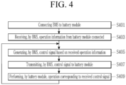
- FIG. 4 illustrates an operation flowchart when the battery management system 10 is connected to the battery module 20_i, in the battery apparatus 1 according to the present disclosure.
- the battery management system 10 is connected to the battery module 20_i (S401).
- the battery management system 10 and the battery module 20_i may be connected through a wire.
- the battery management system 10 and the battery module 20_i may transmit and receive data through UART communication or CAN communication.
- the battery management system 10 receives operation information of the battery module 20_i from the battery module 20_i connected thereto (S403).
- the operation information is information on an operation state being performed by the battery module 20_i, and may include mode information and task information about a task to be performed or being performed by the battery module 20_i in each mode. Furthermore, the operation information may include information about a temperature of the battery cell 210_i in the battery module 20_i, a voltage of the battery cell 210_i, and the like. One mode may include a plurality of tasks of which order is predetermined.
- the battery management system 10 generates a control signal based on the received operation information (S405).
- the battery management system 10 may determine which operation the battery module 20_i is performing, and generate control signals corresponding to respective tasks to sequentially perform tasks included in the corresponding mode.
- the battery management system 10 when there is no next operation to be performed by the battery module 20_i in the mode corresponding to the mode information, may generate a control signal for controlling to perform the first operation of the corresponding mode.
- the battery management system 10 when the operation information including the information on mode 0 is received from the battery module 20_i, may determine that the battery module 20_i is performing no operation. Next, the battery management system 10 may determine a task required for the battery module 20_i based on the operation information including information on the temperature of the battery cell 210_i in the battery module 20_i, the voltage of the battery cell 210_i, and the like, and may generate a control signal that controls to perform the corresponding task.
- the battery management system 10 transmits a control signal to the battery module 20_i (S407).
- the battery module 20_i performs an operation corresponding to the received control signal (S409).
- the battery apparatus even in a case of an unexpected connection failure between the battery management system and the battery module, it is possible to control the battery module to continuously perform the operation.
- the battery management system may be configured in the method in which it transmits only the control signal required to the battery module, disconnects the connection, and controls other battery modules, so that it is possible to control a plurality of battery modules by a small number of battery management systems.
Landscapes
- Engineering & Computer Science (AREA)
- Manufacturing & Machinery (AREA)
- Chemical & Material Sciences (AREA)
- Chemical Kinetics & Catalysis (AREA)
- Electrochemistry (AREA)
- General Chemical & Material Sciences (AREA)
- Power Engineering (AREA)
- Microelectronics & Electronic Packaging (AREA)
- Physics & Mathematics (AREA)
- General Physics & Mathematics (AREA)
- Secondary Cells (AREA)
- Charge And Discharge Circuits For Batteries Or The Like (AREA)
Abstract
Description
- The present disclosure relates to a battery apparatus and a control method thereof.
- A battery management system and a plurality of battery modules transmit and receive data through wires. The battery module performs an operation corresponding to an instruction of the battery management system. In most cases, the battery management system transmits one instruction and then disconnects the connection with the battery module so as to control another battery module.
- However, an unpredictable connection failure between the battery management system and the battery module may occur. In this case, even if the connection between the battery management system and the battery module becomes normal, the battery management system cannot know which operation the battery module is performing.
- The above information disclosed in this Background section is only for enhancement of understanding of the background of the invention, and therefore it may contain information that does not form the prior art that is already known in this country to a person of ordinary skill in the art.
- Embodiments have been made in an effort to provide a battery management system and a battery apparatus that may control a battery module to continuously operate even when the battery management system and the battery module are disconnected and then reconnected.
- An embodiment provides a battery apparatus including: a battery module including a plurality of battery cells; and a battery management system that receives operation information including mode information and task information about an operation being performed by the battery module from the battery module and that generates a control signal with respect to the battery module based on the operation information to transmit it to a battery module connected thereto. Herein, one mode includes a plurality of tasks of which order is predetermined.
- The operation information may further include information about at least one of a temperature and a voltage of a battery cell of each of the battery modules, and when the mode information indicates a default mode indicating that there is no operation being performed by the battery module, the battery management system may generate a control signal based on the information about at least one of the temperature and the voltage of each battery cell.
- When it is determined that there is a next task after the task corresponding to the task information in a mode corresponding to the mode information, the battery management system may generate a control signal controlling the battery module so that the battery module performs the next task.
- When it is determined that there is no next task after the task corresponding to the task information in a mode corresponding to the mode information, the battery management system may generate a control signal controlling the battery module so that the battery module performs a first task of the mode.
- The mode may include at least one of a battery management system initializing mode, a battery module manager initializing mode, a measurement mode, a diagnosis mode, a cell balancing mode, an error mode, and a default mode.
- Another embodiment provides a control method of a battery apparatus, including: transmitting, by a battery module including a plurality of battery cells, operation information on an operation being performed to a battery management system, wherein the operation information includes mode information and task information, and one mode includes a plurality of operations of which order is predetermined; generating, by the battery management system, a control signal with respect to the battery module based on the operation information; and transmitting, by the battery management system, the control signal to the battery module.
- The operation information may further include: information about at least one of a temperature and a voltage of a battery cell of each of the battery modules; the transmitting of the operation information to the battery management system may include transmitting, by the battery module, operation information including mode information indicating a default mode indicating that there is no operation being performed by the battery module, to the battery management system; and the generating of the control signal may include generating, by the battery management system, a control signal based on information on at least one of a temperature and a voltage of each of the battery cells when the mode information indicates the default mode.
- The generating of the control signal may include generating, by the battery management system, when it is determined that there is a next task after the task corresponding to the task information in a mode corresponding to the mode information, a control signal controlling the battery module so that the battery module performs the next task.
- The generating of the control signal may include generating, by the battery management system, when it is determined that there is no next task after the task corresponding to the task information in a mode corresponding to the mode information, a control signal controlling the battery module so that the battery module performs a first task of the mode.
- The mode may include at least one of a battery management system initializing mode, a battery module manager initializing mode, a measurement mode, a diagnosis mode, a cell balancing mode, an error mode, and a default mode. That is, there maybe one or more modes, and the mode or modes may be selected from the list above.
- According to the embodiment of the present disclosure, it is possible to control the battery module to continuously operate even when the battery management system and the battery module are disconnected and then reconnected.
- According to the embodiment of the present disclosure, it is possible to control a plurality of battery modules by using one battery management system.
- At least some of the above and other features of the invention are set out in the claims.
-
-
FIG. 1 illustrates a battery apparatus according to the present disclosure. -
FIG. 2 illustrates a battery module and a battery management system of a battery apparatus according to the present disclosure in more detail. -
FIG. 3 illustrates a mode and a task corresponding to the mode in a battery apparatus according to the present disclosure. -
FIG. 4 illustrates an operation flowchart when a battery management system is connected to a battery module, in a battery apparatus according to the present disclosure. - Hereinafter, embodiments disclosed in the present specification will be described in detail with reference to the accompanying drawings, and in the present specification, the same or similar constituent elements will be denoted by the same or similar reference numerals, and a redundant description thereof will be omitted. The terms "module" and/or "unit, portion, or part" representing constituent element used in the following description are used only in order to make understanding of the specification easier, and thus, these terms do not have meanings or roles that distinguish them from each other by themselves. In addition, in describing embodiments of the present specification, when it is determined that a detailed description of the well-known art associated with the present invention may obscure the gist of the present invention, it will be omitted. Further, the accompanying drawings are provided only in order to allow embodiments disclosed in the present specification to be easily understood and are not to be interpreted as limiting the disclosure of the present specification, and it is to be understood that the present invention includes all modifications, equivalents, and substitutions without departing from the scope of the present invention as defined by the claims.
- Terms including an ordinal number, such as first, second, etc., may be used to describe various elements, but the elements are not limited by the terms. The terms are only used to differentiate one constituent element from other constituent elements.
- It should be understood that, when it is described that an element is "coupled" or "connected" to another element, the element may be "directly coupled" or "directly connected" to the another element, or may be "coupled" or "connected" to the other element through a third element. In contrast, it should be understood that, when it is described that an element is "directly coupled" or "directly connected" to another element, no element is present between the element and the other element.
- In the present application, it should be understood that the term "include", "comprise", "have", or "configure" indicates that a feature, a number, a step, an operation, a constituent element, a part, or a combination thereof described in the specification is present, but does not exclude a possibility of presence or addition of one or more other features, numbers, steps, operations, constituent elements, parts, or combinations, in advance.
-
FIG. 1 illustrates abattery apparatus 1 according to the present disclosure. - The
battery apparatus 1 includes abattery management system 10 and a plurality of battery modules 20_1 to 20_n. - The
battery management system 10 and the plurality of battery modules 20_1 to 20_n may transmit and receive data through UART or CAN communication. - For example, the
battery management system 10 may be connected to one battery module 20_i (i is one of natural numbers from 1 to n) of the plurality of battery modules 20_1 to 20_n to transmit a control signal for controlling an operation of the battery module 20_i to the battery module 20_i. - The plurality of battery modules 20_1 to 20_n are connected in series to supply desired power to
connection terminals battery apparatus 1. - The plurality of battery modules 20_1 to 20_n may be connected to the
battery management system 10 through respective wires.FIG. 1 illustrates a case in which the first battery module 20_1 is connected to thebattery management system 10. For example, thebattery management system 10 and the plurality of battery modules 20_1 to 20_n may be connected by using a daisy chain method. - In addition, each battery module 20_i may transmit information on an operation state of the battery module 20_i to the
battery management system 10. -
FIG. 2 illustrates the battery module 20_i and thebattery management system 10 of thebattery apparatus 1 according to the present disclosure in more detail. - The battery module 20_i may include a plurality of battery cells 210_i and a battery module manager (BMM) 230_i.
- The plurality of battery cells 210_i may be rechargeable secondary batteries. The plurality of battery cells 210_i are connected in series to form the battery module 20_i.
- The battery module manager 230_i may include a controller 231_i, a sensing portion 233_i that measures a temperature of the battery cell 210_i, a voltage measuring portion 235_i that measures a voltage of each of the battery cells 210_i, and a memory 237_i.
- The controller 231_i may control overall constituent elements of the battery module 20_i to perform an operation corresponding to the control signal based on the control signal received from the
battery management system 10. - The sensing portion 233_i may measure a cell temperature of each of the plurality of battery cells 210_i. The sensing portion 233_i may generate a voltage signal or a current signal indicating the measured cell temperature to transmit it to the controller 231_i.
- The voltage measuring portion 235_i may measure a cell voltage of each of the plurality of battery cells 210_i. The voltage measuring portion 235_i may generate a voltage signal or a current signal indicating the measured cell voltage to transmit it to the controller 231_i.
- The memory 237_i may include data required for the controller 231 to control the battery module 20_i. In addition, the memory 237_i may include operation information on an operation state currently being performed by the battery module 20_i. The operation information may include mode information and task information on a task to be performed or being performed by the battery module 20_i in each mode. Furthermore, the operation information may include information on the cell temperature measured by the sensing portion 233_i, the cell voltage measured by the voltage measuring portion 235_i, and the like.
- The controller 231_i may transmit operation information of the battery module 20_i to the
battery management system 10 according to a request of thebattery management system 10. - The
battery management system 10 may generate a control signal for controlling the battery module 20_i based on the operation information received from the battery module manager 230_i. Specifically, thebattery management system 10 may generate the control signal based on mode information and task information, a cell voltage, and a cell temperature included in the operation information. - The control signal may include information on a mode to be performed in the future by the battery module 20_i and a task corresponding thereto. One mode may include a plurality of tasks whose order is predetermined. The
battery management system 10 may determine an operation required for the battery module 20_i based on the operation information to generate a control signal corresponding thereto. Each mode and the task corresponding thereto may be stored in advance in thebattery management system 10. - For example, the
battery management system 10 may detect a cell requiring cell balancing based on a plurality of cell voltages included in the operation information, and may generate a control signal for performing a cell balancing operation. - Generally, the
battery management system 10 may generate a control signal corresponding to each task so that each battery module 20_i performs operations included in any one mode. In addition, thebattery management system 10 may transmit a control signal corresponding to each battery module 20_i. - When the battery module manager 230_i receives a corresponding control signal from the
battery management system 10, as described above, the battery module manager 230_i may control the battery module 20_i to perform the task corresponding to the control signal. - The
battery management system 10 and the battery module 20_i may be disconnected while the battery module 20_i is performing a task included in a mode corresponding to the control signal. In order for the battery module 20_i to proceed to a next task of the corresponding mode, it must receive a control signal corresponding to the next task from thebattery management system 10. However, since thebattery management system 10 and the battery module 20_i are disconnected, the battery module 20_i cannot receive a new control signal from thebattery management system 10, so that it continuously performs the task corresponding to the control signal received directly before they are disconnected. - Hereinafter, mode information and task information included in operation information will be described with reference to
FIG. 3 . -
FIG. 3 illustrates a mode and a task corresponding to the mode in thebattery apparatus 1 according to the present disclosure. - As shown in
FIG. 3 , thebattery apparatus 1 may operate in a plurality of modes. A plurality of modes includes abattery management system 10 initializing mode, a battery module manager 230_i initializing mode, a measurement mode, a diagnosis mode, a cell balancing mode, an error mode, and a default mode. In addition, there may be a mode in which the battery module manager 230_i performs emergency discharge of the battery cell 210_i for 10 seconds. - In addition, each mode may include M (M is a natural number) sequential tasks required to perform each mode.
- The
battery management system 10 initializing mode may include a task of initializing all data stored in thebattery management system 10, and then a task of connecting thebattery management system 10 and the battery module manager 230_i. For example, there may be a case in which a power source is connected to thebattery management system 10. - The battery module manager 230_i initializing mode may include a task of initializing all data stored in the battery module manager 230_i. This may be performed while the
battery management system 10 initializes all data stored in thebattery management system 10 or during an arbitrary operation. For example, when thebattery management system 10 detects an abnormal operation of the battery module manager 230_i, it may generate a control signal including the battery module manager 230_i initializing mode. - The measurement mode may include at least one of a task in which the sensing portion 233_i of the battery module manager 230_i measures a cell temperature and a task in which the voltage measuring portion 235_i measures a cell voltage.
- The diagnosis mode may include a task in which the
battery management system 10 checks whether there is an abnormality in a specific item set in advance in the battery module manager 230_i. For example, the diagnosis mode may include a charging pump confirmation task, a sensing portion confirmation task, a balancing switch confirmation task, an ADC confirmation task, and a communication data confirmation task. - The cell balancing mode may include a series of tasks required for cell balancing of the battery module 20_i.
- The error mode may include a task performed by the
battery management system 10 when an abnormality is detected during operation. For example, when thebattery management system 10 detects deterioration in reliability of data collected from the battery module manager 230_i, an error may be detected in communication with the battery module manager 230_i. - The
battery management system 10 may transmit a control signal for controlling the battery module 20_i to performtask 1 ofmode 2 to the battery module 20_i. The battery module 20_i may perform an operation corresponding totask 1 ofmode 2 based on the received control signal. Here, the operation corresponding totask 1 may be an operation of measuring a battery cell temperature or an operation of measuring a cell voltage. - The
battery management system 10 may receive a report on completion oftask 1 from the battery module 20_i, or may control the battery module 20_i to perform a next task after a predetermined time has elapsed from starting oftask 1. That is, thebattery management system 10 may generate a control signal for controlling to performtask 2 ofmode 2 to transmit the generated control signal to the battery module 20_i. The battery module 20_i may perform an operation corresponding totask 2 ofmode 2 based on the received control signal. - That is, when the
battery management system 10 controls the battery module 20_i inmode 2, thebattery management system 10 may generate 17 control signals to transmit them to the battery module 20_i so that the battery module 20_i performs up to an operation corresponding totask 17 ofmode 2. - When the
battery management system 10 and the battery module 20_i are disconnected, the battery module 20_i may repeatedly perform an operation corresponding to a control signal last received from thebattery management system 10. - In this case, when the
battery management system 10 and the battery module 20_i are connected again, the battery module 20_i may transmit operation information including task information and mode information corresponding to the operation being performed to thebattery management system 10. - For example, when the
battery management system 10 and the battery module 20_i are disconnected after the control signal for controlling thebattery management system 10 to perform the operation corresponding totask 2 ofmode 2 is transmitted to the battery module 20_i, the battery module 20_i may continuously perform the operation corresponding totask 2 ofmode 2. Thereafter, when thebattery management system 10 and the battery module 20_i are connected again, the battery module 20_i may transmit operation information including information onmode 2 and information ontask 2 corresponding to the currently performed operation to thebattery management system 10. - The
battery management system 10 may confirm that the battery module 20_i performs the operation corresponding totask 2 ofmode 2 based on operation information including information onmode 2 and information ontask 2 based on the operation information of the battery module 20_i. Accordingly, thebattery management system 10 may generate a control signal so that the battery module 20_i performs an operation corresponding to task 3, which is a next step oftask 2 inmode 2. Accordingly, the continuity of the operation of the battery module 20_i may be maintained. - When the
battery management system 10 and the battery module 20_i are disconnected after the control signal for controlling thebattery management system 10 to performmode 2 andtask 17 is transmitted to the battery module 20_i, the battery module 20_i may continuously perform the operation corresponding totask 17 ofmode 2. Thereafter, when thebattery management system 10 and the battery module 20_i are connected again, the battery module 20_i may transmit operation information including information onmode 2 and information ontask 17 to thebattery management system 10. However, as shown inFIG. 3 , there is no next task oftask 17 inmode 2. Accordingly, thebattery management system 10 may generate a control signal for controlling to performtask 0, which is the first task of the corresponding mode, rather than a control signal for performing the next task of the operation being performed. Thereafter, the battery module 20_i may perform an operation corresponding totask 0 ofmode 2. - When the battery module 20_i is performing no operation, the battery module 20_i may transmit operation information including mode information on the default mode (for example, mode 0) indicating that the battery module is not operating in any mode to the
battery management system 10. Accordingly, thebattery management system 10 may determine that the battery module 20_i is performing no operation, determine the operation required for the battery module 20_i, and generate a control signal corresponding thereto. -
FIG. 4 illustrates an operation flowchart when thebattery management system 10 is connected to the battery module 20_i, in thebattery apparatus 1 according to the present disclosure. - First, the
battery management system 10 is connected to the battery module 20_i (S401). - The
battery management system 10 and the battery module 20_i may be connected through a wire. Thebattery management system 10 and the battery module 20_i may transmit and receive data through UART communication or CAN communication. - The
battery management system 10 receives operation information of the battery module 20_i from the battery module 20_i connected thereto (S403). - The operation information is information on an operation state being performed by the battery module 20_i, and may include mode information and task information about a task to be performed or being performed by the battery module 20_i in each mode. Furthermore, the operation information may include information about a temperature of the battery cell 210_i in the battery module 20_i, a voltage of the battery cell 210_i, and the like. One mode may include a plurality of tasks of which order is predetermined.
- The
battery management system 10 generates a control signal based on the received operation information (S405). - The
battery management system 10 may determine which operation the battery module 20_i is performing, and generate control signals corresponding to respective tasks to sequentially perform tasks included in the corresponding mode. - Alternatively, the
battery management system 10, when there is no next operation to be performed by the battery module 20_i in the mode corresponding to the mode information, may generate a control signal for controlling to perform the first operation of the corresponding mode. - The
battery management system 10, when the operation information including the information onmode 0 is received from the battery module 20_i, may determine that the battery module 20_i is performing no operation. Next, thebattery management system 10 may determine a task required for the battery module 20_i based on the operation information including information on the temperature of the battery cell 210_i in the battery module 20_i, the voltage of the battery cell 210_i, and the like, and may generate a control signal that controls to perform the corresponding task. - The
battery management system 10 transmits a control signal to the battery module 20_i (S407). - The battery module 20_i performs an operation corresponding to the received control signal (S409).
- According to the battery apparatus according to the present disclosure, even in a case of an unexpected connection failure between the battery management system and the battery module, it is possible to control the battery module to continuously perform the operation.
- According to the battery apparatus according to the present disclosure, the battery management system may be configured in the method in which it transmits only the control signal required to the battery module, disconnects the connection, and controls other battery modules, so that it is possible to control a plurality of battery modules by a small number of battery management systems.
- The steps constituting the method according to the embodiments may be performed in an appropriate order unless explicitly stated or contradicted by the order. The present invention is not necessarily limited to the described order of steps. In the present invention, use of all examples or illustrative terms (e.g., etc.) is merely for describing the present invention in detail, and thus the scope of the present invention is not limited thereto. In addition, a person of ordinary skill in the art can recognize that various modifications, combinations, and changes may be made within the scope of the claims or their equivalents.
- While this invention has been described in connection with what is presently considered to be practical embodiments, it is to be understood that the invention is not limited to the disclosed embodiments, but, on the contrary, is intended to cover various modifications and equivalent arrangements included within the scope of the appended claims.
Claims (10)
- A battery apparatus comprising:a battery module including a plurality of battery cells; anda battery management system configured to:receive from the battery module operation information including mode information and task information about an operation being performed by the battery modulegenerate a control signal with respect to the battery module based on the operation information; andtransmit the control signal to a battery module connected thereto, wherein at least one mode includes a plurality of tasks of which order is predetermined.
- The battery apparatus of claim 1, whereinthe operation information further includes information about at least one of a temperature and a voltage of a battery cell of each of the battery modules, andwhen the mode information indicates a default mode indicating that there is no operation being performed by the battery module, the battery management system is configured to generate a control signal based on the information about at least one of the temperature and the voltage of each battery cell.
- The battery apparatus of claim 1 or 2, wherein
when determining that there is a next task of the task corresponding to the task information in a mode corresponding to the mode information, the battery management system is configured to generate a control signal controlling the battery module so that the battery module performs the next task. - The battery apparatus of claim 1, 2 or 3, wherein
when determining that there is no next task of the task corresponding to the task information in a mode corresponding to the mode information, the battery management system is configured to generate a control signal controlling the battery module so that the battery module performs a first task of the mode. - The battery apparatus of any one of claims 1 to 4, wherein
the mode includes at least one of a battery management system initializing mode, a battery module manager initializing mode, a measurement mode, a diagnosis mode, a cell balancing mode, an error mode, and a default mode. - A control method of a battery apparatus, comprising:transmitting, by a battery module including a plurality of battery cells, operation information on an operation being performed to a battery management system, wherein the operation information includes mode information and task information, and at least one mode includes a plurality of operations of which order is predetermined;generating, by the battery management system, a control signal with respect to the battery module based on the operation information; andtransmitting, by the battery management system, the control signal to the battery module.
- The control method of the battery apparatus of claim 6, whereinthe operation information further includes information about at least one of a temperature and a voltage of a battery cell of each of the battery modules,the transmitting of the operation information to the battery management system includestransmitting, by the battery module, operation information including mode information indicating a default mode indicating that there is no operation being performed by the battery module, to the battery management system, andthe generating of the control signal includesgenerating, by the battery management system, a control signal based on information on at least one of a temperature and a voltage of each of the battery cells when the mode information indicates the default mode.
- The control method of the battery apparatus of claim 6 or 7, whereinthe generating of the control signal includesgenerating, by the battery management system, when determining that there is a next task of the task corresponding to the task information in a mode corresponding to the mode information, a control signal controlling the battery module so that the battery module performs the next task.
- The control method of the battery apparatus of claim 6, 7 or 8, whereinthe generating of the control signal includesgenerating, by the battery management system, when determining that there is no next task of the task corresponding to the task information in a mode corresponding to the mode information, a control signal controlling the battery module so that the battery module performs a first task of the mode.
- The control method of the battery apparatus of any one of claims 6 to 9, wherein
the mode includes at least one of a battery management system initializing mode, a battery module manager initializing mode, a measurement mode, a diagnosis mode, a cell balancing mode, an error mode, and a default mode.
Applications Claiming Priority (1)
| Application Number | Priority Date | Filing Date | Title |
|---|---|---|---|
| KR1020210135989A KR102694548B1 (en) | 2021-10-13 | 2021-10-13 | Battery apparatus and control method thereof |
Publications (2)
| Publication Number | Publication Date |
|---|---|
| EP4167426A1 true EP4167426A1 (en) | 2023-04-19 |
| EP4167426B1 EP4167426B1 (en) | 2024-07-24 |
Family
ID=83689852
Family Applications (1)
| Application Number | Title | Priority Date | Filing Date |
|---|---|---|---|
| EP22200463.2A Active EP4167426B1 (en) | 2021-10-13 | 2022-10-10 | Battery apparatus and control method thereof |
Country Status (6)
| Country | Link |
|---|---|
| US (1) | US20230115975A1 (en) |
| EP (1) | EP4167426B1 (en) |
| KR (1) | KR102694548B1 (en) |
| CN (1) | CN115967144A (en) |
| HU (1) | HUE069069T2 (en) |
| PL (1) | PL4167426T3 (en) |
Families Citing this family (1)
| Publication number | Priority date | Publication date | Assignee | Title |
|---|---|---|---|---|
| KR20240156121A (en) | 2023-04-21 | 2024-10-29 | 주식회사 엘지에너지솔루션 | An electrode assembly and a method of manufacturing the same |
Citations (1)
| Publication number | Priority date | Publication date | Assignee | Title |
|---|---|---|---|---|
| EP2806525A2 (en) * | 2013-05-23 | 2014-11-26 | Samsung SDI Co., Ltd. | Battery management system |
Family Cites Families (2)
| Publication number | Priority date | Publication date | Assignee | Title |
|---|---|---|---|---|
| WO2009076418A1 (en) * | 2007-12-11 | 2009-06-18 | Antonio Trigiani | Battery management system |
| KR102247391B1 (en) * | 2016-07-25 | 2021-05-03 | 삼성에스디아이 주식회사 | Battery system |
-
2021
- 2021-10-13 KR KR1020210135989A patent/KR102694548B1/en active Active
-
2022
- 2022-10-09 CN CN202211225807.6A patent/CN115967144A/en active Pending
- 2022-10-10 EP EP22200463.2A patent/EP4167426B1/en active Active
- 2022-10-10 HU HUE22200463A patent/HUE069069T2/en unknown
- 2022-10-10 PL PL22200463.2T patent/PL4167426T3/en unknown
- 2022-10-11 US US17/963,558 patent/US20230115975A1/en active Pending
Patent Citations (1)
| Publication number | Priority date | Publication date | Assignee | Title |
|---|---|---|---|---|
| EP2806525A2 (en) * | 2013-05-23 | 2014-11-26 | Samsung SDI Co., Ltd. | Battery management system |
Also Published As
| Publication number | Publication date |
|---|---|
| HUE069069T2 (en) | 2025-02-28 |
| US20230115975A1 (en) | 2023-04-13 |
| PL4167426T3 (en) | 2024-10-21 |
| KR20230052674A (en) | 2023-04-20 |
| EP4167426B1 (en) | 2024-07-24 |
| KR102694548B1 (en) | 2024-08-09 |
| CN115967144A (en) | 2023-04-14 |
Similar Documents
| Publication | Publication Date | Title |
|---|---|---|
| US20240332648A1 (en) | Slave BMS Inspection System and Method | |
| US9885760B2 (en) | Battery apparatus and battery system | |
| JP7127762B2 (en) | Battery diagnostic system and method | |
| US8334673B2 (en) | Voltage monitoring apparatus including active power source, low consumption power source, and a failure diagnosis section to disconnect active power source as a result of failure | |
| CN102439472A (en) | Battery voltage monitoring device | |
| US11796605B2 (en) | Battery cell diagnostic device and method | |
| KR20190075489A (en) | Apparatus and method for diagnosing communication fault | |
| US20210325472A1 (en) | System for obtaining battery state information | |
| WO2017203265A1 (en) | Methods and apparatus for energy storage | |
| JP2009300173A (en) | Storage battery monitoring system | |
| EP4167426B1 (en) | Battery apparatus and control method thereof | |
| US10756393B2 (en) | Method for preventing duplicate allocation of ID to battery modules | |
| US20150185291A1 (en) | Switched capacitor battery unit monitoring system | |
| EP3698153B1 (en) | Method and system for testing a rechargeable battery | |
| JP2013207902A (en) | Battery control device | |
| KR20210022470A (en) | Battery management system and battery management method | |
| US20240348060A1 (en) | Method for charging accumulators of devices of a wired security system, the wired security system and a control unit of the wired security system which are configured to charge the accumulators of the devices according to the method | |
| EP4614172A1 (en) | Management method for battery data and battery management system providing same | |
| JP7804637B2 (en) | Battery control device and power storage system | |
| US20260039122A1 (en) | Battery device and application determination method of battery device | |
| RU2852652C1 (en) | Traction substation storage battery monitoring system | |
| WO2026008675A1 (en) | Vehicle charging circuit condition determination | |
| JP2024088449A (en) | Battery system and method for controlling battery system | |
| WO2026008591A1 (en) | Controlling navigation system of a vehicle | |
| CN117693685A (en) | Device and method for managing batteries |
Legal Events
| Date | Code | Title | Description |
|---|---|---|---|
| PUAI | Public reference made under article 153(3) epc to a published international application that has entered the european phase |
Free format text: ORIGINAL CODE: 0009012 |
|
| STAA | Information on the status of an ep patent application or granted ep patent |
Free format text: STATUS: REQUEST FOR EXAMINATION WAS MADE |
|
| 17P | Request for examination filed |
Effective date: 20221010 |
|
| AK | Designated contracting states |
Kind code of ref document: A1 Designated state(s): AL AT BE BG CH CY CZ DE DK EE ES FI FR GB GR HR HU IE IS IT LI LT LU LV MC ME MK MT NL NO PL PT RO RS SE SI SK SM TR |
|
| P01 | Opt-out of the competence of the unified patent court (upc) registered |
Effective date: 20230712 |
|
| GRAP | Despatch of communication of intention to grant a patent |
Free format text: ORIGINAL CODE: EPIDOSNIGR1 |
|
| STAA | Information on the status of an ep patent application or granted ep patent |
Free format text: STATUS: GRANT OF PATENT IS INTENDED |
|
| INTG | Intention to grant announced |
Effective date: 20240223 |
|
| INTG | Intention to grant announced |
Effective date: 20240226 |
|
| GRAS | Grant fee paid |
Free format text: ORIGINAL CODE: EPIDOSNIGR3 |
|
| GRAA | (expected) grant |
Free format text: ORIGINAL CODE: 0009210 |
|
| STAA | Information on the status of an ep patent application or granted ep patent |
Free format text: STATUS: THE PATENT HAS BEEN GRANTED |
|
| AK | Designated contracting states |
Kind code of ref document: B1 Designated state(s): AL AT BE BG CH CY CZ DE DK EE ES FI FR GB GR HR HU IE IS IT LI LT LU LV MC ME MK MT NL NO PL PT RO RS SE SI SK SM TR |
|
| REG | Reference to a national code |
Ref country code: GB Ref legal event code: FG4D |
|
| REG | Reference to a national code |
Ref country code: CH Ref legal event code: EP |
|
| REG | Reference to a national code |
Ref country code: IE Ref legal event code: FG4D Ref country code: DE Ref legal event code: R096 Ref document number: 602022004791 Country of ref document: DE |
|
| REG | Reference to a national code |
Ref country code: SE Ref legal event code: TRGR |
|
| REG | Reference to a national code |
Ref country code: LT Ref legal event code: MG9D |
|
| REG | Reference to a national code |
Ref country code: NL Ref legal event code: MP Effective date: 20240724 |
|
| PG25 | Lapsed in a contracting state [announced via postgrant information from national office to epo] |
Ref country code: PT Free format text: LAPSE BECAUSE OF FAILURE TO SUBMIT A TRANSLATION OF THE DESCRIPTION OR TO PAY THE FEE WITHIN THE PRESCRIBED TIME-LIMIT Effective date: 20241125 |
|
| PG25 | Lapsed in a contracting state [announced via postgrant information from national office to epo] |
Ref country code: NL Free format text: LAPSE BECAUSE OF FAILURE TO SUBMIT A TRANSLATION OF THE DESCRIPTION OR TO PAY THE FEE WITHIN THE PRESCRIBED TIME-LIMIT Effective date: 20240724 |
|
| PG25 | Lapsed in a contracting state [announced via postgrant information from national office to epo] |
Ref country code: PT Free format text: LAPSE BECAUSE OF FAILURE TO SUBMIT A TRANSLATION OF THE DESCRIPTION OR TO PAY THE FEE WITHIN THE PRESCRIBED TIME-LIMIT Effective date: 20241125 Ref country code: NL Free format text: LAPSE BECAUSE OF FAILURE TO SUBMIT A TRANSLATION OF THE DESCRIPTION OR TO PAY THE FEE WITHIN THE PRESCRIBED TIME-LIMIT Effective date: 20240724 |
|
| PG25 | Lapsed in a contracting state [announced via postgrant information from national office to epo] |
Ref country code: NO Free format text: LAPSE BECAUSE OF FAILURE TO SUBMIT A TRANSLATION OF THE DESCRIPTION OR TO PAY THE FEE WITHIN THE PRESCRIBED TIME-LIMIT Effective date: 20241024 |
|
| PG25 | Lapsed in a contracting state [announced via postgrant information from national office to epo] |
Ref country code: FI Free format text: LAPSE BECAUSE OF FAILURE TO SUBMIT A TRANSLATION OF THE DESCRIPTION OR TO PAY THE FEE WITHIN THE PRESCRIBED TIME-LIMIT Effective date: 20240724 Ref country code: GR Free format text: LAPSE BECAUSE OF FAILURE TO SUBMIT A TRANSLATION OF THE DESCRIPTION OR TO PAY THE FEE WITHIN THE PRESCRIBED TIME-LIMIT Effective date: 20241025 |
|
| PG25 | Lapsed in a contracting state [announced via postgrant information from national office to epo] |
Ref country code: BG Free format text: LAPSE BECAUSE OF FAILURE TO SUBMIT A TRANSLATION OF THE DESCRIPTION OR TO PAY THE FEE WITHIN THE PRESCRIBED TIME-LIMIT Effective date: 20240724 |
|
| PG25 | Lapsed in a contracting state [announced via postgrant information from national office to epo] |
Ref country code: LV Free format text: LAPSE BECAUSE OF FAILURE TO SUBMIT A TRANSLATION OF THE DESCRIPTION OR TO PAY THE FEE WITHIN THE PRESCRIBED TIME-LIMIT Effective date: 20240724 |
|
| PG25 | Lapsed in a contracting state [announced via postgrant information from national office to epo] |
Ref country code: IS Free format text: LAPSE BECAUSE OF FAILURE TO SUBMIT A TRANSLATION OF THE DESCRIPTION OR TO PAY THE FEE WITHIN THE PRESCRIBED TIME-LIMIT Effective date: 20241124 |
|
| PG25 | Lapsed in a contracting state [announced via postgrant information from national office to epo] |
Ref country code: HR Free format text: LAPSE BECAUSE OF FAILURE TO SUBMIT A TRANSLATION OF THE DESCRIPTION OR TO PAY THE FEE WITHIN THE PRESCRIBED TIME-LIMIT Effective date: 20240724 |
|
| PG25 | Lapsed in a contracting state [announced via postgrant information from national office to epo] |
Ref country code: ES Free format text: LAPSE BECAUSE OF FAILURE TO SUBMIT A TRANSLATION OF THE DESCRIPTION OR TO PAY THE FEE WITHIN THE PRESCRIBED TIME-LIMIT Effective date: 20240724 Ref country code: RS Free format text: LAPSE BECAUSE OF FAILURE TO SUBMIT A TRANSLATION OF THE DESCRIPTION OR TO PAY THE FEE WITHIN THE PRESCRIBED TIME-LIMIT Effective date: 20241024 |
|
| PG25 | Lapsed in a contracting state [announced via postgrant information from national office to epo] |
Ref country code: RS Free format text: LAPSE BECAUSE OF FAILURE TO SUBMIT A TRANSLATION OF THE DESCRIPTION OR TO PAY THE FEE WITHIN THE PRESCRIBED TIME-LIMIT Effective date: 20241024 Ref country code: NO Free format text: LAPSE BECAUSE OF FAILURE TO SUBMIT A TRANSLATION OF THE DESCRIPTION OR TO PAY THE FEE WITHIN THE PRESCRIBED TIME-LIMIT Effective date: 20241024 Ref country code: LV Free format text: LAPSE BECAUSE OF FAILURE TO SUBMIT A TRANSLATION OF THE DESCRIPTION OR TO PAY THE FEE WITHIN THE PRESCRIBED TIME-LIMIT Effective date: 20240724 Ref country code: IS Free format text: LAPSE BECAUSE OF FAILURE TO SUBMIT A TRANSLATION OF THE DESCRIPTION OR TO PAY THE FEE WITHIN THE PRESCRIBED TIME-LIMIT Effective date: 20241124 Ref country code: HR Free format text: LAPSE BECAUSE OF FAILURE TO SUBMIT A TRANSLATION OF THE DESCRIPTION OR TO PAY THE FEE WITHIN THE PRESCRIBED TIME-LIMIT Effective date: 20240724 Ref country code: GR Free format text: LAPSE BECAUSE OF FAILURE TO SUBMIT A TRANSLATION OF THE DESCRIPTION OR TO PAY THE FEE WITHIN THE PRESCRIBED TIME-LIMIT Effective date: 20241025 Ref country code: FI Free format text: LAPSE BECAUSE OF FAILURE TO SUBMIT A TRANSLATION OF THE DESCRIPTION OR TO PAY THE FEE WITHIN THE PRESCRIBED TIME-LIMIT Effective date: 20240724 Ref country code: ES Free format text: LAPSE BECAUSE OF FAILURE TO SUBMIT A TRANSLATION OF THE DESCRIPTION OR TO PAY THE FEE WITHIN THE PRESCRIBED TIME-LIMIT Effective date: 20240724 Ref country code: BG Free format text: LAPSE BECAUSE OF FAILURE TO SUBMIT A TRANSLATION OF THE DESCRIPTION OR TO PAY THE FEE WITHIN THE PRESCRIBED TIME-LIMIT Effective date: 20240724 |
|
| REG | Reference to a national code |
Ref country code: HU Ref legal event code: AG4A Ref document number: E069069 Country of ref document: HU |
|
| PG25 | Lapsed in a contracting state [announced via postgrant information from national office to epo] |
Ref country code: RO Free format text: LAPSE BECAUSE OF FAILURE TO SUBMIT A TRANSLATION OF THE DESCRIPTION OR TO PAY THE FEE WITHIN THE PRESCRIBED TIME-LIMIT Effective date: 20240724 Ref country code: DK Free format text: LAPSE BECAUSE OF FAILURE TO SUBMIT A TRANSLATION OF THE DESCRIPTION OR TO PAY THE FEE WITHIN THE PRESCRIBED TIME-LIMIT Effective date: 20240724 Ref country code: SM Free format text: LAPSE BECAUSE OF FAILURE TO SUBMIT A TRANSLATION OF THE DESCRIPTION OR TO PAY THE FEE WITHIN THE PRESCRIBED TIME-LIMIT Effective date: 20240724 |
|
| PG25 | Lapsed in a contracting state [announced via postgrant information from national office to epo] |
Ref country code: EE Free format text: LAPSE BECAUSE OF FAILURE TO SUBMIT A TRANSLATION OF THE DESCRIPTION OR TO PAY THE FEE WITHIN THE PRESCRIBED TIME-LIMIT Effective date: 20240724 |
|
| PG25 | Lapsed in a contracting state [announced via postgrant information from national office to epo] |
Ref country code: CZ Free format text: LAPSE BECAUSE OF FAILURE TO SUBMIT A TRANSLATION OF THE DESCRIPTION OR TO PAY THE FEE WITHIN THE PRESCRIBED TIME-LIMIT Effective date: 20240724 |
|
| REG | Reference to a national code |
Ref country code: DE Ref legal event code: R097 Ref document number: 602022004791 Country of ref document: DE |
|
| PG25 | Lapsed in a contracting state [announced via postgrant information from national office to epo] |
Ref country code: IT Free format text: LAPSE BECAUSE OF FAILURE TO SUBMIT A TRANSLATION OF THE DESCRIPTION OR TO PAY THE FEE WITHIN THE PRESCRIBED TIME-LIMIT Effective date: 20240724 Ref country code: SK Free format text: LAPSE BECAUSE OF FAILURE TO SUBMIT A TRANSLATION OF THE DESCRIPTION OR TO PAY THE FEE WITHIN THE PRESCRIBED TIME-LIMIT Effective date: 20240724 |
|
| PLBE | No opposition filed within time limit |
Free format text: ORIGINAL CODE: 0009261 |
|
| STAA | Information on the status of an ep patent application or granted ep patent |
Free format text: STATUS: NO OPPOSITION FILED WITHIN TIME LIMIT |
|
| 26N | No opposition filed |
Effective date: 20250425 |
|
| PG25 | Lapsed in a contracting state [announced via postgrant information from national office to epo] |
Ref country code: MC Free format text: LAPSE BECAUSE OF FAILURE TO SUBMIT A TRANSLATION OF THE DESCRIPTION OR TO PAY THE FEE WITHIN THE PRESCRIBED TIME-LIMIT Effective date: 20240724 |
|
| PG25 | Lapsed in a contracting state [announced via postgrant information from national office to epo] |
Ref country code: LU Free format text: LAPSE BECAUSE OF NON-PAYMENT OF DUE FEES Effective date: 20241010 Ref country code: BE Free format text: LAPSE BECAUSE OF NON-PAYMENT OF DUE FEES Effective date: 20241031 |
|
| REG | Reference to a national code |
Ref country code: BE Ref legal event code: MM Effective date: 20241031 |
|
| PGFP | Annual fee paid to national office [announced via postgrant information from national office to epo] |
Ref country code: FR Payment date: 20250930 Year of fee payment: 4 |
|
| PG25 | Lapsed in a contracting state [announced via postgrant information from national office to epo] |
Ref country code: IE Free format text: LAPSE BECAUSE OF NON-PAYMENT OF DUE FEES Effective date: 20241010 |
|
| REG | Reference to a national code |
Ref country code: AT Ref legal event code: UEP Ref document number: 1707215 Country of ref document: AT Kind code of ref document: T Effective date: 20240724 |
|
| PGFP | Annual fee paid to national office [announced via postgrant information from national office to epo] |
Ref country code: HU Payment date: 20251105 Year of fee payment: 4 |
|
| PGFP | Annual fee paid to national office [announced via postgrant information from national office to epo] |
Ref country code: DE Payment date: 20250930 Year of fee payment: 4 |
|
| PGFP | Annual fee paid to national office [announced via postgrant information from national office to epo] |
Ref country code: AT Payment date: 20260113 Year of fee payment: 4 |
|
| PGFP | Annual fee paid to national office [announced via postgrant information from national office to epo] |
Ref country code: SE Payment date: 20251001 Year of fee payment: 4 |
|
| PGFP | Annual fee paid to national office [announced via postgrant information from national office to epo] |
Ref country code: PL Payment date: 20251007 Year of fee payment: 4 |
|
| PG25 | Lapsed in a contracting state [announced via postgrant information from national office to epo] |
Ref country code: CY Free format text: LAPSE BECAUSE OF FAILURE TO SUBMIT A TRANSLATION OF THE DESCRIPTION OR TO PAY THE FEE WITHIN THE PRESCRIBED TIME-LIMIT; INVALID AB INITIO Effective date: 20221010 |