EP4167406A1 - Monitoring substations of a power grid - Google Patents
Monitoring substations of a power grid Download PDFInfo
- Publication number
- EP4167406A1 EP4167406A1 EP21202678.5A EP21202678A EP4167406A1 EP 4167406 A1 EP4167406 A1 EP 4167406A1 EP 21202678 A EP21202678 A EP 21202678A EP 4167406 A1 EP4167406 A1 EP 4167406A1
- Authority
- EP
- European Patent Office
- Prior art keywords
- environmental condition
- section
- substation
- controller
- sensor
- Prior art date
- Legal status (The legal status is an assumption and is not a legal conclusion. Google has not performed a legal analysis and makes no representation as to the accuracy of the status listed.)
- Pending
Links
Images


Classifications
-
- H—ELECTRICITY
- H02—GENERATION; CONVERSION OR DISTRIBUTION OF ELECTRIC POWER
- H02B—BOARDS, SUBSTATIONS OR SWITCHING ARRANGEMENTS FOR THE SUPPLY OR DISTRIBUTION OF ELECTRIC POWER
- H02B1/00—Frameworks, boards, panels, desks, casings; Details of substations or switching arrangements
- H02B1/56—Cooling; Ventilation
-
- G—PHYSICS
- G01—MEASURING; TESTING
- G01M—TESTING STATIC OR DYNAMIC BALANCE OF MACHINES OR STRUCTURES; TESTING OF STRUCTURES OR APPARATUS, NOT OTHERWISE PROVIDED FOR
- G01M3/00—Investigating fluid-tightness of structures
- G01M3/02—Investigating fluid-tightness of structures by using fluid or vacuum
- G01M3/04—Investigating fluid-tightness of structures by using fluid or vacuum by detecting the presence of fluid at the leakage point
- G01M3/16—Investigating fluid-tightness of structures by using fluid or vacuum by detecting the presence of fluid at the leakage point using electric detection means
- G01M3/18—Investigating fluid-tightness of structures by using fluid or vacuum by detecting the presence of fluid at the leakage point using electric detection means for pipes, cables or tubes; for pipe joints or seals; for valves; for welds; for containers, e.g. radiators
- G01M3/186—Investigating fluid-tightness of structures by using fluid or vacuum by detecting the presence of fluid at the leakage point using electric detection means for pipes, cables or tubes; for pipe joints or seals; for valves; for welds; for containers, e.g. radiators for containers, e.g. radiators
-
- G—PHYSICS
- G01—MEASURING; TESTING
- G01M—TESTING STATIC OR DYNAMIC BALANCE OF MACHINES OR STRUCTURES; TESTING OF STRUCTURES OR APPARATUS, NOT OTHERWISE PROVIDED FOR
- G01M3/00—Investigating fluid-tightness of structures
- G01M3/002—Investigating fluid-tightness of structures by using thermal means
-
- G—PHYSICS
- G01—MEASURING; TESTING
- G01M—TESTING STATIC OR DYNAMIC BALANCE OF MACHINES OR STRUCTURES; TESTING OF STRUCTURES OR APPARATUS, NOT OTHERWISE PROVIDED FOR
- G01M3/00—Investigating fluid-tightness of structures
- G01M3/02—Investigating fluid-tightness of structures by using fluid or vacuum
- G01M3/04—Investigating fluid-tightness of structures by using fluid or vacuum by detecting the presence of fluid at the leakage point
-
- H—ELECTRICITY
- H02—GENERATION; CONVERSION OR DISTRIBUTION OF ELECTRIC POWER
- H02J—ELECTRIC POWER NETWORKS; CIRCUIT ARRANGEMENTS OR SYSTEMS FOR SUPPLYING OR DISTRIBUTING ELECTRIC POWER; SYSTEMS FOR STORING ELECTRIC ENERGY
- H02J13/00—Circuit arrangements for providing remote monitoring or remote control of equipment in a power distribution network
- H02J13/18—Circuit arrangements for providing remote monitoring or remote control of equipment in a power distribution network characterised by the remotely-controlled equipment, e.g. converters or transformers
- H02J13/333—Circuit arrangements for providing remote monitoring or remote control of equipment in a power distribution network characterised by the remotely-controlled equipment, e.g. converters or transformers the equipment forming part of substations
Definitions
- the present disclosure relates to a method and a device for monitoring substations of a power grid, in particular to a method and a device for monitoring heaters and/or for determining water ingress in substations of a power grid.
- Heaters are used to reduce humidity and to increase temperature in cold environments. A heater failure can cause damage to electric equipment inside the cabinet potentially leading to failure of e.g. circuit breakers. The same holds true for water ingress into the cabinet.
- the prevailing heater monitoring method in high voltage substations relies on current sensors in combination with temperature and/or humidity sensors. A logic is applied to trigger alarm and warnings checking if a current flow through the heater is measured.
- the present disclosure relates to a method for monitoring a plurality of heaters and/or determining water ingress in at least one substation.
- the method comprises receiving, by a controller from a first sensor a first at least one environmental condition of a first section of the at least one substation; receiving, by the controller from a second sensor a second at least one environmental condition of a second section of the at least one substation; and providing a warning signal, by the controller, according to a difference between the first at least one environmental condition and the second at least one environmental condition.
- the providing the warning signal comprises providing the warning signal when the difference between the first at least one environmental condition and the second at least one environmental condition is above a set threshold.
- the section of the at least one substation is a cabinet or a cubicle.
- the first section is in a first substation and the second section is in a second substation.
- the first at least one environmental condition comprises a first temperature of the first section
- the second at least one environmental condition comprises a second temperature of the second section
- the first at least one environmental condition comprises a first humidity of the first section
- the second at least one environmental condition comprises a second humidity of the second section
- the warning signal comprises information regarding a heater failure of and/or water ingress into at least one of the first and the second section of the at least one substation.
- the difference between the first at least one environmental condition and the second at least one environmental condition is indicative of a heater failure and/or water ingress into at least one of the first or the second section of the at least one substation.
- the first at least one environmental condition comprises a first temperature of the first section and a first humidity of the first section and the second at least one environmental condition comprises a second temperature and a second humidity of the second section.
- the providing the warning signal comprises providing a warning signal related to a heater failure when the difference between the first at least one environmental condition and the second at least one environmental condition is above a first set threshold.
- the providing the warning signal comprises providing a warning signal related to water ingress when the difference between the first at least one environmental condition and the second at least one environmental condition is above a second set threshold.
- the second threshold is a greater than the first threshold.
- the first sensor is located at the bottom of the first section and the second sensor is located at the bottom of the second section.
- the difference between the first at least one environmental condition and the second at least one environmental condition is particularly suited for the detection of water ingress, but not limited to.
- the first sensor is located in the vicinity of a heater in the first section and the second sensor is located in the vicinity of a heater in the second section.
- the difference between the first at least one environmental condition and the second at least one environmental condition is particularly suited for the detection of heater failure, but not limited to.
- water ingress describes, but without limitation, the process of liquid entering a container, in this case the substation and/or the section thereof, through a physical opening.
- water ingress describes, but without limitation, the process of liquid forming within a container, in this case the substation and/or the section thereof, due to at least one environmental condition either inside or outside of said container or the combination of both inside and outside of said container.
- water ingress describes condensation within said container. More particularly, said condensation is caused by the temperature changes either inside or outside of said container or the temperature changes in both inside and outside of said container.
- the threshold is set by using a self-learning model.
- the at least one self-learning model is trained by processing the received environmental conditions or at least one pre-processed data to determine at least two clusters representative of at least one difference of environmental conditions.
- the method comprises receiving, by a controller from a third sensor a third at least one environmental condition of a third section of the at least one substation; wherein the step of providing the warning signal comprises providing the warning signal according to differences among the first at least one environmental condition, the second at least one environmental condition, and the third at least one environmental condition.
- the method comprises identifying a location of an error in the heater system according to the differences among the first at least one environmental condition, the second at least one environmental condition, and the third at least one environmental condition.
- the threshold is set by using at least one self-learning algorithm.
- training of the at least one self-learning algorithm comprises processing the at least one the received environmental conditions or at least one pre-processed data to determine at least two clusters representative of various differences of environmental conditions.
- the present disclosure also relates to a controller for monitoring a plurality of heaters and/or determining water ingress in at least one substation comprising a processor configured to receive from a first sensor a first at least one environmental condition of a first section of the at least one substation; receive from a second sensor a second at least one environmental condition of a second section of the at least one substation; and provide a warning signal according to a difference between the first at least one environmental condition and the second at least one environmental condition.
- the controller is configured to provide the warning signal when the difference between the first at least one environmental condition and the second at least one environmental condition is above a set threshold.
- the controller sets the threshold by using at least one self-learning model.
- the controller trains the at least one self-learning model by processing the received environmental conditions or at least one pre-processed data to determine at least two clusters representative of at least one difference of environmental conditions.
- the present disclosure also relates to a system comprising the above mentioned controller and a plurality of heaters in at least one substation comprising a first sensor generating a first at least one environmental condition of a first section of the at least one substation and a second sensor generating a second at least one environmental condition of a second section of the at least one substation.
- the present disclosure is not limited to the exemplary embodiments and applications described and illustrated herein. Additionally, the specific order and/or hierarchy of steps in the methods disclosed herein are merely exemplary approaches. Based upon design preferences, the specific order or hierarchy of steps of the disclosed methods or processes can be re-arranged while remaining within the scope of the present disclosure. Thus, those of ordinary skill in the art will understand that the methods and techniques disclosed herein present various steps or acts in a sample order, and the present disclosure is not limited to the specific order or hierarchy presented unless expressly stated otherwise.
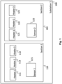
- Fig.1 shows an exemplary substation of a power grid according to an embodiment of the present disclosure.
- the at least one substation 100 comprising a first section 110 and a second section 120.
- the first section 110 comprises a first sensor 115 and a first heater 111, a second heater 112 and a third heater 113.
- the second section 120 of the first substation 100 comprises a second sensor 125 and a fourth heater 121, a fifth heater 122 and a sixth heater 123.
- the first sensor 115 monitors the heaters 111 ⁇ 113 in the first section 110 and senses at least one environmental condition of the first section 110 of the first substation 100.
- the second sensor 125 monitors the heaters 121 ⁇ 123 in the second section 120 and senses at least one environmental condition of the second section 120 of the substation 100.
- the first sensor 115 is located at a fixed position within the first section 110 of the at least one substation 100 with respect to a reference point either within or outside of the first section 110.
- the second sensor 125 may be located at fixed position within the second section 120 of the at least one substation 100 with respect to a reference point either within or outside of the second section 120.
- the warning signal comprises information regarding a heater failure of and/or water ingress into at least one of the first 110 and the second section 120 of the at least one substation 100.
- the difference between the first at least one environmental condition and the second at least one environmental condition may be indicative of a heater failure and/or water ingress into at least one of the first 110 or the second section 120 of the at least one substation 100, particularly when the environmental condition is humidity and temperature.
- the providing the warning signal comprises providing a warning signal related to a heater failure when the difference between the first at least one environmental condition and the second at least one environmental condition is above a first set threshold.
- the providing the warning signal comprises providing a warning signal related to water ingress when the difference between the first at least one environmental condition and the second at least one environmental condition is above a second set threshold.
- the second threshold is a greater than the first threshold.
- the first sensor 115 is located at the bottom of the first section 110 and the second sensor 125 is located at the bottom of the second section 120.
- the difference between the first at least one environmental condition and the second at least one environmental condition is particularly suited for the detection of water ingress, but not limited to, e.g. a heater failure may be detected as well.
- the first sensor 115 is located in the vicinity of a heater/heaters in the first section and the second sensor is located in the vicinity of a heater/heaters in the second section.
- the difference between the first at least one environmental condition and the second at least one environmental condition is particularly suited for the detection of heater failure, but not limited to, e.g. water ingress may be detected as well.
- water ingress describes, but without limitation, the process of liquid entering a container, in this case the substation and/or the section thereof, through a physical opening.
- water ingress describes, but without limitation, the process of liquid forming within a container, in this case the substation and/or the section thereof, due to at least one environmental condition either inside or outside of said container or the combination of both inside and outside of said container.
- water ingress describes condensation within said container. More particularly, said condensation is caused by the temperature changes either inside or outside of said container or the temperature changes in both inside and outside of said container.
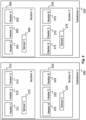
- the first substation 200 comprises a first section 210 and a second section 220.
- the first section 210 of the first substation 200 comprises a first sensor 215, a first heater 211, a second heater 212, and a third heater 213.
- the second section 220 of the first substation 200 comprises a second sensor 225 and a fourth heater 221, a fifth heater 222 and a sixth heater 223.
- the second substation 250 comprises a first section 260 and a second section 270.
- the first section 260 of the second substation 250 comprises a first sensor 265, a first heater 261, a second heater 262, and a third heater 263.
- the second section 270 of the second substation 250 comprises a second sensor 275 and a fourth heater 271, a fifth heater 272 and a sixth heater 273.
- the first sensor 215 in the first section 210 of the first substation 200 monitors the heaters 211 ⁇ 213 in the first section 210 of the first substation 200 and senses at least one environmental condition of the first section 210 of the first substation 200.
- the second sensor 225 in the second section 220 of the first substation 200 monitors the heaters 221 ⁇ 223 in the second section 220 of the first substation 200 and senses at least one environmental condition of the second section 220 of the first substation 200.
- the first sensor 265 in the first section 260 of the second substation 250 monitors the heaters 261 ⁇ 263 in the first section 260 of the second substation 250 and senses at least one environmental condition of the first section 260 of the second substation 250.
- the second sensor 275 in the second section 270 of the second substation 250 monitors the heaters 271 ⁇ 273 in the second section 270 of the second substation 250 and senses at least one environmental condition of the second section 270 of the second substation 250.
- At least one substation comprises at least one section.
- the at least one section comprises a plurality of heaters and at least one sensor.
- the number of above-mentioned components is not limited by the embodiments shown in figures.
- a section of the at least one substation is a cabinet or a cubicle.
- a first section is in a first substation and a second section is in a second substation. That is, a first section is the first section 210 of the first substation 200 and a second section is the second section 270 of the second substation 250, or any other combination of sections of substations.
- the first at least one environmental condition comprises a first temperature of the first section
- the second at least one environmental condition comprises a second temperature of the second section
- the first at least one environmental condition comprises a first humidity of the first section
- the second at least one environmental condition comprises a second humidity of the second section
- Fig.3 shows an exemplary controller and exemplary signals according to an embodiment of the present disclosure.
- the controller 300 receives a first environmental condition 301 of the first section 110 of the first substation 100.
- the controller 320 further receives a second environmental condition 302 of the second section 120 of the first substation 100.
- the controller provides a warning signal 304 according to a difference between the first environmental condition 301 and the second environmental condition 302.
- a controller 300 receives a first environmental condition 301 of the first section 210 of the first substation 200.
- the controller 320 further receives a second environmental condition 302 of the first section 260 of the second substation 250.
- the controller provides a warning signal 304 according to a difference between the first environmental condition 301 and the second environmental condition 302.
- a controller receives n environmental condition(s) from any one of sections of any one of substations.
- a controller 300 receives environmental conditions from any other combination of sections of substations.
- the controller receives further environmental conditions of the first section 110, the second section 120 and/or other sections of the first substation 100 and/or other substations.
- the controller provides warning signals 304 according to the differences among the first environmental condition 301, the second environmental condition 302, and, if any, further received environmental conditions.
- the controller is located in each of the first substation and the second substation. Additionally or alternatively, the controller 300 is a central unit located in or outside of the at least one substation. According to an embodiment, the controller 300 is further configured to communicate unidirectionally or bidirectionally with another at least one entity which is configured to communicate.
- the controller 300 is further configured to calculate and/or memorize the relation or correlation between the first at least one environmental condition and the second at least one environmental condition within a section of the at least one substation.
- the controller 300 is further configured to generate the warning signals by monitoring whether the first at least one environmental condition and the second at least one environmental condition follows the calculated and/or memorized relation or correlation between the first at least one environmental condition and the second at least one environmental condition.
- the providing the warning signal comprises providing the warning signal when the difference between the first at least one environmental condition and the second at least one environmental condition is above a set threshold.
- a location of an error in the heater system is identified according to the differences among the first at least one environmental condition, the second at least one environmental condition, and the third at least one environmental condition.
- the threshold is set by using at least one self-learning algorithm.
- training of the at least one self-learning algorithm comprises processing the at least one the received environmental condition or at least one pre-processed data to determine at least two clusters representative of various differences of environmental conditions.
- the controller 400 comprises a self-learning engine 410.
- the self-learning engine 410 comprises a plurality of machine-readable instructions and/or at least one self-learning algorithm.
- the self-learning algorithm is trained using the first environmental condition 401 and/or the second environmental condition 402. It is understood by the skilled person that, if any, further received environmental conditions can be used to train the algorithm thereof.
- the self-learning engine 410 sets a threshold to the difference between the first at least one environmental condition 401 and the second environmental condition 402 and feeds the set threshold to a decision engine 420.
- the decision engine either alone or in conjunction with other functional blocks of the controller 400 determines to generate a warning signal 404.
- the controller 450 comprises a decision engine 420.
- a self-learning engine 460 is a separate unit from the controller 450 and comprises a plurality of machine-readable instructions and/or at least one self-learning algorithm.
- the self-learning algorithm is trained using the first environmental condition 451 and/or the second environmental condition 452. It is understood by the skilled person that, if any, further received environmental conditions can be used to train the algorithm thereof.
- the self-learning engine 460 sets a threshold to the difference between the first at least one environmental condition 451 and the second environmental condition 452 and feeds the set threshold to the controller 450.
- the controller 450 determines to generate a warning signal 454.
- the number of environmental conditions to train the self-learning engine 410 is not limited to the number of environmental conditions illustrated in Fig.4 .
- any reference to an element herein using a designation such as "first,” “second,” and so forth does not generally limit the quantity or order of those elements. Rather, these designations can be used herein as a convenient means of distinguishing between two or more elements or instances of an element. Thus, a reference to first and second elements does not mean that only two elements can be employed, or that the first element must precede the second element in some manner.
- any of the various illustrative logical blocks, units, processors, means, circuits, methods and functions described in connection with the aspects disclosed herein can be implemented by electronic hardware (e.g., a digital implementation, an analog implementation, or a combination of the two), firmware, various forms of program or design code incorporating instructions (which can be referred to herein, for convenience, as "software” or a "software unit”), or any combination of these techniques.
- a processor, device, component, circuit, structure, machine, unit, etc. can be configured to perform one or more of the functions described herein.
- IC integrated circuit
- DSP digital signal processor
- ASIC application specific integrated circuit
- FPGA field programmable gate array
- the logical blocks, units, and circuits can further include antennas and/or transceivers to communicate with various components within the network or within the device.
- a general purpose processor can be a microprocessor, but in the alternative, the processor can be any conventional processor, controller, or state machine.
- a processor can also be implemented as a combination of computing devices, e.g., a combination of a DSP and a microprocessor, a plurality of microprocessors, one or more microprocessors in conjunction with a DSP core, or any other suitable configuration to perform the functions described herein. If implemented in software, the functions can be stored as one or more instructions or code on a computer-readable medium. Thus, the steps of a method or algorithm disclosed herein can be implemented as software stored on a computer-readable medium.
- Computer-readable media includes both computer storage media and communication media including any medium that can be enabled to transfer a computer program or code from one place to another.
- a storage media can be any available media that can be accessed by a computer.
- such computer-readable media can include RAM, ROM, EEPROM, CD-ROM or other optical disk storage, magnetic disk storage or other magnetic storage devices, or any other medium that can be used to store desired program code in the form of instructions or data structures and that can be accessed by a computer.
- memory or other storage may be employed in embodiments of the present disclosure.
- memory or other storage may be employed in embodiments of the present disclosure.
- any suitable distribution of functionality between different functional units, processing logic elements or domains may be used without detracting from the present disclosure.
- functionality illustrated to be performed by separate processing logic elements, or controllers may be performed by the same processing logic element, or controller.
- references to specific functional units are only references to a suitable means for providing the described functionality, rather than indicative of a strict logical or physical structure or organization.
Landscapes
- Physics & Mathematics (AREA)
- General Physics & Mathematics (AREA)
- Engineering & Computer Science (AREA)
- Power Engineering (AREA)
- Emergency Alarm Devices (AREA)
- Patch Boards (AREA)
Abstract
Description
- The present disclosure relates to a method and a device for monitoring substations of a power grid, in particular to a method and a device for monitoring heaters and/or for determining water ingress in substations of a power grid.
- Heaters are used to reduce humidity and to increase temperature in cold environments. A heater failure can cause damage to electric equipment inside the cabinet potentially leading to failure of e.g. circuit breakers. The same holds true for water ingress into the cabinet.
- The prevailing heater monitoring method in high voltage substations relies on current sensors in combination with temperature and/or humidity sensors. A logic is applied to trigger alarm and warnings checking if a current flow through the heater is measured.
- However, current sensors are often not designed for low temperature applications (e.g. below -20°C), which are relevant for heater monitoring. Furthermore, integration of multiple sensors can cause additional failures, thus monitoring using current sensors, particularly in combination with temperature and/or humidity sensors are not preferred. Thus, there is a need to improve the monitoring of substations of a power grid, in particular of monitoring heaters in substations and/or determining water ingress in substations.
- The above-mentioned objects are achieved with the features of the independent claims. Dependent claims define preferred embodiments of the disclosure.
- In particular, the present disclosure relates to a method for monitoring a plurality of heaters and/or determining water ingress in at least one substation. The method comprises receiving, by a controller from a first sensor a first at least one environmental condition of a first section of the at least one substation; receiving, by the controller from a second sensor a second at least one environmental condition of a second section of the at least one substation; and providing a warning signal, by the controller, according to a difference between the first at least one environmental condition and the second at least one environmental condition.
- Various embodiments may advantageously implement the following features:
According to an embodiment, the providing the warning signal comprises providing the warning signal when the difference between the first at least one environmental condition and the second at least one environmental condition is above a set threshold. - According to an embodiment, the section of the at least one substation is a cabinet or a cubicle.
- According to an embodiment, the first section is in a first substation and the second section is in a second substation.
- According to an embodiment, the first at least one environmental condition comprises a first temperature of the first section, and the second at least one environmental condition comprises a second temperature of the second section.
- According to an embodiment, the first at least one environmental condition comprises a first humidity of the first section, and the second at least one environmental condition comprises a second humidity of the second section.
- According to an embodiment, the warning signal comprises information regarding a heater failure of and/or water ingress into at least one of the first and the second section of the at least one substation. According to an embodiment, the difference between the first at least one environmental condition and the second at least one environmental condition is indicative of a heater failure and/or water ingress into at least one of the first or the second section of the at least one substation. According to an embodiment, the first at least one environmental condition comprises a first temperature of the first section and a first humidity of the first section and the second at least one environmental condition comprises a second temperature and a second humidity of the second section. According to an embodiment, the providing the warning signal comprises providing a warning signal related to a heater failure when the difference between the first at least one environmental condition and the second at least one environmental condition is above a first set threshold. According to an embodiment, the providing the warning signal comprises providing a warning signal related to water ingress when the difference between the first at least one environmental condition and the second at least one environmental condition is above a second set threshold. According to an embodiment, the second threshold is a greater than the first threshold.
- According to an embodiment, the first sensor is located at the bottom of the first section and the second sensor is located at the bottom of the second section. In such a configuration, the difference between the first at least one environmental condition and the second at least one environmental condition is particularly suited for the detection of water ingress, but not limited to.
- According to an embodiment, the first sensor is located in the vicinity of a heater in the first section and the second sensor is located in the vicinity of a heater in the second section. In such a configuration, the difference between the first at least one environmental condition and the second at least one environmental condition is particularly suited for the detection of heater failure, but not limited to.
- According to an embodiment, water ingress describes, but without limitation, the process of liquid entering a container, in this case the substation and/or the section thereof, through a physical opening. In addition or as an alternative, according to an embodiment, water ingress describes, but without limitation, the process of liquid forming within a container, in this case the substation and/or the section thereof, due to at least one environmental condition either inside or outside of said container or the combination of both inside and outside of said container. Particularly, water ingress describes condensation within said container. More particularly, said condensation is caused by the temperature changes either inside or outside of said container or the temperature changes in both inside and outside of said container.
- According to an embodiment, the threshold is set by using a self-learning model.
- According to an embodiment, the at least one self-learning model is trained by processing the received environmental conditions or at least one pre-processed data to determine at least two clusters representative of at least one difference of environmental conditions.
- According to an embodiment, the method comprises receiving, by a controller from a third sensor a third at least one environmental condition of a third section of the at least one substation; wherein the step of providing the warning signal comprises providing the warning signal according to differences among the first at least one environmental condition, the second at least one environmental condition, and the third at least one environmental condition.
- According to an embodiment, the method comprises identifying a location of an error in the heater system according to the differences among the first at least one environmental condition, the second at least one environmental condition, and the third at least one environmental condition.
- According to an embodiment, the threshold is set by using at least one self-learning algorithm.
- According to an embodiment, training of the at least one self-learning algorithm comprises processing the at least one the received environmental conditions or at least one pre-processed data to determine at least two clusters representative of various differences of environmental conditions.
- The present disclosure also relates to a controller for monitoring a plurality of heaters and/or determining water ingress in at least one substation comprising a processor configured to receive from a first sensor a first at least one environmental condition of a first section of the at least one substation; receive from a second sensor a second at least one environmental condition of a second section of the at least one substation; and provide a warning signal according to a difference between the first at least one environmental condition and the second at least one environmental condition.
- Various embodiments may advantageously implement the following features:
According to an embodiment, the controller is configured to provide the warning signal when the difference between the first at least one environmental condition and the second at least one environmental condition is above a set threshold. - According to an embodiment, the controller sets the threshold by using at least one self-learning model.
- According to an embodiment, the controller trains the at least one self-learning model by processing the received environmental conditions or at least one pre-processed data to determine at least two clusters representative of at least one difference of environmental conditions.
- The present disclosure also relates to a system comprising the above mentioned controller and a plurality of heaters in at least one substation comprising a first sensor generating a first at least one environmental condition of a first section of the at least one substation and a second sensor generating a second at least one environmental condition of a second section of the at least one substation.
- The exemplary embodiments disclosed herein are directed to providing features that will become readily apparent by reference to the following description when taken in conjunction with the accompanying drawings. In accordance with various embodiments, exemplary systems, methods, and devices are disclosed herein. It is understood, however, that these embodiments are presented by way of example and not limitation, and it will be apparent to those of ordinary skill in the art who read the present disclosure that various modifications to the disclosed embodiments can be made while remaining within the scope of the present disclosure.
- Thus, the present disclosure is not limited to the exemplary embodiments and applications described and illustrated herein. Additionally, the specific order and/or hierarchy of steps in the methods disclosed herein are merely exemplary approaches. Based upon design preferences, the specific order or hierarchy of steps of the disclosed methods or processes can be re-arranged while remaining within the scope of the present disclosure. Thus, those of ordinary skill in the art will understand that the methods and techniques disclosed herein present various steps or acts in a sample order, and the present disclosure is not limited to the specific order or hierarchy presented unless expressly stated otherwise.
- The above and other aspects and their implementations are described in greater detail in the drawings, the descriptions, and the claims.
-
Fig.1 shows an exemplary substation of a power grid according to an embodiment of the present disclosure. -
Fig.2 shows an exemplary substation of a power grid comprising two substations according to an embodiment of the present disclosure. -
Fig. 3 shows an exemplary controller and exemplary signals according to an embodiment of the present disclosure. -
Fig. 4 (a) and (b) show exemplary controllers comprising a self-learning engine and a decision engine and exemplary signals according to embodiments of the present disclosure. - In the following, exemplary embodiments of the disclosure will be described. It is noted that some aspects of any one of the described embodiments may also be found in some other embodiments unless otherwise stated or obvious. However, for increased intelligibility, each aspect will only be described in detail when first mentioned and any repeated description of the same aspect will be omitted.
-
Fig.1 shows an exemplary substation of a power grid according to an embodiment of the present disclosure. - In the embodiment shown in
Fig.1 , the at least onesubstation 100 comprising afirst section 110 and asecond section 120. Thefirst section 110 comprises afirst sensor 115 and afirst heater 111, asecond heater 112 and athird heater 113. Thesecond section 120 of thefirst substation 100 comprises asecond sensor 125 and afourth heater 121, afifth heater 122 and asixth heater 123. Thefirst sensor 115 monitors theheaters 111∼113 in thefirst section 110 and senses at least one environmental condition of thefirst section 110 of thefirst substation 100. Thesecond sensor 125 monitors theheaters 121∼123 in thesecond section 120 and senses at least one environmental condition of thesecond section 120 of thesubstation 100. - According to an embodiment, the
first sensor 115 is located at a fixed position within thefirst section 110 of the at least onesubstation 100 with respect to a reference point either within or outside of thefirst section 110. Furthermore, thesecond sensor 125 may be located at fixed position within thesecond section 120 of the at least onesubstation 100 with respect to a reference point either within or outside of thesecond section 120. - According to an embodiment, the warning signal comprises information regarding a heater failure of and/or water ingress into at least one of the first 110 and the
second section 120 of the at least onesubstation 100. In other words, the difference between the first at least one environmental condition and the second at least one environmental condition may be indicative of a heater failure and/or water ingress into at least one of the first 110 or thesecond section 120 of the at least onesubstation 100, particularly when the environmental condition is humidity and temperature. According to an embodiment, the providing the warning signal comprises providing a warning signal related to a heater failure when the difference between the first at least one environmental condition and the second at least one environmental condition is above a first set threshold. According to an embodiment, the providing the warning signal comprises providing a warning signal related to water ingress when the difference between the first at least one environmental condition and the second at least one environmental condition is above a second set threshold. According to an embodiment, the second threshold is a greater than the first threshold. - According to an embodiment, the
first sensor 115 is located at the bottom of thefirst section 110 and thesecond sensor 125 is located at the bottom of thesecond section 120. In such a configuration, the difference between the first at least one environmental condition and the second at least one environmental condition is particularly suited for the detection of water ingress, but not limited to, e.g. a heater failure may be detected as well. - According to an embodiment, the
first sensor 115 is located in the vicinity of a heater/heaters in the first section and the second sensor is located in the vicinity of a heater/heaters in the second section. In such a configuration, the difference between the first at least one environmental condition and the second at least one environmental condition is particularly suited for the detection of heater failure, but not limited to, e.g. water ingress may be detected as well. - According to an embodiment, water ingress describes, but without limitation, the process of liquid entering a container, in this case the substation and/or the section thereof, through a physical opening. In addition or as an alternative, according to an embodiment, water ingress describes, but without limitation, the process of liquid forming within a container, in this case the substation and/or the section thereof, due to at least one environmental condition either inside or outside of said container or the combination of both inside and outside of said container. Particularly, water ingress describes condensation within said container. More particularly, said condensation is caused by the temperature changes either inside or outside of said container or the temperature changes in both inside and outside of said container.
- In the embodiment shown in
Fig.2 , there are twosubstations first substation 200 comprises afirst section 210 and asecond section 220. Thefirst section 210 of thefirst substation 200 comprises afirst sensor 215, afirst heater 211, asecond heater 212, and athird heater 213. Thesecond section 220 of thefirst substation 200 comprises asecond sensor 225 and afourth heater 221, afifth heater 222 and asixth heater 223. Thesecond substation 250 comprises afirst section 260 and asecond section 270. Thefirst section 260 of thesecond substation 250 comprises afirst sensor 265, afirst heater 261, asecond heater 262, and athird heater 263. Thesecond section 270 of thesecond substation 250 comprises asecond sensor 275 and afourth heater 271, afifth heater 272 and asixth heater 273. - The
first sensor 215 in thefirst section 210 of thefirst substation 200 monitors theheaters 211∼213 in thefirst section 210 of thefirst substation 200 and senses at least one environmental condition of thefirst section 210 of thefirst substation 200. Thesecond sensor 225 in thesecond section 220 of thefirst substation 200 monitors theheaters 221∼223 in thesecond section 220 of thefirst substation 200 and senses at least one environmental condition of thesecond section 220 of thefirst substation 200. Thefirst sensor 265 in thefirst section 260 of thesecond substation 250 monitors theheaters 261∼263 in thefirst section 260 of thesecond substation 250 and senses at least one environmental condition of thefirst section 260 of thesecond substation 250. Thesecond sensor 275 in thesecond section 270 of thesecond substation 250 monitors theheaters 271∼273 in thesecond section 270 of thesecond substation 250 and senses at least one environmental condition of thesecond section 270 of thesecond substation 250. - It is understood by the skilled person that at least one substation comprises at least one section. The at least one section comprises a plurality of heaters and at least one sensor. Thus, it is understood by the skilled person that the number of above-mentioned components is not limited by the embodiments shown in figures.
- According to an embodiment, a section of the at least one substation is a cabinet or a cubicle.
- According to an embodiment, a first section is in a first substation and a second section is in a second substation. That is, a first section is the
first section 210 of thefirst substation 200 and a second section is thesecond section 270 of thesecond substation 250, or any other combination of sections of substations. - According to an embodiment, the first at least one environmental condition comprises a first temperature of the first section, and the second at least one environmental condition comprises a second temperature of the second section.
- According to an embodiment, the first at least one environmental condition comprises a first humidity of the first section, and the second at least one environmental condition comprises a second humidity of the second section.
-
Fig.3 shows an exemplary controller and exemplary signals according to an embodiment of the present disclosure. - In the embodiment shown in
Fig.3 , thecontroller 300 receives a firstenvironmental condition 301 of thefirst section 110 of thefirst substation 100. The controller 320 further receives a secondenvironmental condition 302 of thesecond section 120 of thefirst substation 100. The controller provides awarning signal 304 according to a difference between the firstenvironmental condition 301 and the secondenvironmental condition 302. Alternatively or in addition, acontroller 300 receives a firstenvironmental condition 301 of thefirst section 210 of thefirst substation 200. The controller 320 further receives a secondenvironmental condition 302 of thefirst section 260 of thesecond substation 250. The controller provides awarning signal 304 according to a difference between the firstenvironmental condition 301 and the secondenvironmental condition 302. Alternatively or in addition, a controller receives n environmental condition(s) from any one of sections of any one of substations. Alternatively or in addition, acontroller 300 receives environmental conditions from any other combination of sections of substations. Although omitted for simplicity, it is understood by the skilled person that the controller receives further environmental conditions of thefirst section 110, thesecond section 120 and/or other sections of thefirst substation 100 and/or other substations. It is further understood by the skilled person that the controller provides warning signals 304 according to the differences among the firstenvironmental condition 301, the secondenvironmental condition 302, and, if any, further received environmental conditions. - According to an embodiment, the controller is located in each of the first substation and the second substation. Additionally or alternatively, the
controller 300 is a central unit located in or outside of the at least one substation. According to an embodiment, thecontroller 300 is further configured to communicate unidirectionally or bidirectionally with another at least one entity which is configured to communicate. - According to an embodiment, the
controller 300 is further configured to calculate and/or memorize the relation or correlation between the first at least one environmental condition and the second at least one environmental condition within a section of the at least one substation. - According to an embodiment, the
controller 300 is further configured to generate the warning signals by monitoring whether the first at least one environmental condition and the second at least one environmental condition follows the calculated and/or memorized relation or correlation between the first at least one environmental condition and the second at least one environmental condition. - According to an embodiment, the providing the warning signal comprises providing the warning signal when the difference between the first at least one environmental condition and the second at least one environmental condition is above a set threshold.
- According to an embodiment, a location of an error in the heater system is identified according to the differences among the first at least one environmental condition, the second at least one environmental condition, and the third at least one environmental condition.
- According to an embodiment, the threshold is set by using at least one self-learning algorithm.
- According to an embodiment, training of the at least one self-learning algorithm comprises processing the at least one the received environmental condition or at least one pre-processed data to determine at least two clusters representative of various differences of environmental conditions.
- In the embodiment shown in
Fig.4 (a) , thecontroller 400 comprises a self-learning engine 410. The self-learning engine 410 comprises a plurality of machine-readable instructions and/or at least one self-learning algorithm. The self-learning algorithm is trained using the firstenvironmental condition 401 and/or the secondenvironmental condition 402. It is understood by the skilled person that, if any, further received environmental conditions can be used to train the algorithm thereof. The self-learning engine 410 sets a threshold to the difference between the first at least oneenvironmental condition 401 and the secondenvironmental condition 402 and feeds the set threshold to adecision engine 420. The decision engine either alone or in conjunction with other functional blocks of thecontroller 400 determines to generate awarning signal 404. - In the embodiment shown in
Fig.4 (b) , thecontroller 450 comprises adecision engine 420. A self-learning engine 460 is a separate unit from thecontroller 450 and comprises a plurality of machine-readable instructions and/or at least one self-learning algorithm. The self-learning algorithm is trained using the firstenvironmental condition 451 and/or the secondenvironmental condition 452. It is understood by the skilled person that, if any, further received environmental conditions can be used to train the algorithm thereof. The self-learning engine 460 sets a threshold to the difference between the first at least oneenvironmental condition 451 and the secondenvironmental condition 452 and feeds the set threshold to thecontroller 450. Thecontroller 450 determines to generate awarning signal 454. - It is understood by the skilled person that the number of environmental conditions to train the self-
learning engine 410 is not limited to the number of environmental conditions illustrated inFig.4 . - While various embodiments of the present disclosure have been described above, it should be understood that they have been presented by way of example only, and not by way of limitation. Likewise, the various diagrams may depict an example architectural or configuration, which are provided to enable persons of ordinary skill in the art to understand exemplary features and functions of the present disclosure. Such persons would understand, however, that the present disclosure is not restricted to the illustrated example architectures or configurations, but can be implemented using a variety of alternative architectures and configurations. Additionally, as would be understood by persons of ordinary skill in the art, one or more features of one embodiment can be combined with one or more features of another embodiment described herein. Thus, the breadth and scope of the present disclosure should not be limited by any of the above-described exemplary embodiments.
- It is also understood that any reference to an element herein using a designation such as "first," "second," and so forth does not generally limit the quantity or order of those elements. Rather, these designations can be used herein as a convenient means of distinguishing between two or more elements or instances of an element. Thus, a reference to first and second elements does not mean that only two elements can be employed, or that the first element must precede the second element in some manner.
- Additionally, a person having ordinary skill in the art would understand that information and signals can be represented using any of a variety of different technologies and techniques. For example, data, instructions, commands, information, signals, bits and symbols, for example, which may be referenced in the above description can be represented by voltages, currents, electromagnetic waves, magnetic fields or particles, optical fields or particles, or any combination thereof.
- A skilled person would further appreciate that any of the various illustrative logical blocks, units, processors, means, circuits, methods and functions described in connection with the aspects disclosed herein can be implemented by electronic hardware (e.g., a digital implementation, an analog implementation, or a combination of the two), firmware, various forms of program or design code incorporating instructions (which can be referred to herein, for convenience, as "software" or a "software unit"), or any combination of these techniques.
- To clearly illustrate this interchangeability of hardware, firmware and software, various illustrative components, blocks, units, circuits, and steps have been described above generally in terms of their functionality. Whether such functionality is implemented as hardware, firmware or software, or a combination of these techniques, depends upon the particular application and design constraints imposed on the overall system. Skilled artisans can implement the described functionality in various ways for each particular application, but such implementation decisions do not cause a departure from the scope of the present disclosure. In accordance with various embodiments, a processor, device, component, circuit, structure, machine, unit, etc. can be configured to perform one or more of the functions described herein. The term "configured to" or "configured for" as used herein with respect to a specified operation or function refers to a processor, device, component, circuit, structure, machine, unit, etc. that is physically constructed, programmed and/or arranged to perform the specified operation or function.
- Furthermore, a skilled person would understand that various illustrative methods, logical blocks, units, devices, components and circuits described herein can be implemented within or performed by an integrated circuit (IC) that can include a general purpose processor, a digital signal processor (DSP), an application specific integrated circuit (ASIC), a field programmable gate array (FPGA) or other programmable logic device, or any combination thereof. The logical blocks, units, and circuits can further include antennas and/or transceivers to communicate with various components within the network or within the device. A general purpose processor can be a microprocessor, but in the alternative, the processor can be any conventional processor, controller, or state machine. A processor can also be implemented as a combination of computing devices, e.g., a combination of a DSP and a microprocessor, a plurality of microprocessors, one or more microprocessors in conjunction with a DSP core, or any other suitable configuration to perform the functions described herein. If implemented in software, the functions can be stored as one or more instructions or code on a computer-readable medium. Thus, the steps of a method or algorithm disclosed herein can be implemented as software stored on a computer-readable medium.
- Computer-readable media includes both computer storage media and communication media including any medium that can be enabled to transfer a computer program or code from one place to another. A storage media can be any available media that can be accessed by a computer. By way of example, and not limitation, such computer-readable media can include RAM, ROM, EEPROM, CD-ROM or other optical disk storage, magnetic disk storage or other magnetic storage devices, or any other medium that can be used to store desired program code in the form of instructions or data structures and that can be accessed by a computer.
- Additionally, memory or other storage, as well as communication components, may be employed in embodiments of the present disclosure. It will be appreciated that, for clarity purposes, the above description has described embodiments of the present disclosure with reference to different functional units and processors. However, it will be apparent that any suitable distribution of functionality between different functional units, processing logic elements or domains may be used without detracting from the present disclosure. For example, functionality illustrated to be performed by separate processing logic elements, or controllers, may be performed by the same processing logic element, or controller. Hence, references to specific functional units are only references to a suitable means for providing the described functionality, rather than indicative of a strict logical or physical structure or organization.
- Various modifications to the implementations described in this disclosure will be readily apparent to those skilled in the art, and the general principles defined herein can be applied to other implementations without departing from the scope of this disclosure. Thus, the disclosure is not intended to be limited to the implementations shown herein, but is to be accorded the widest scope consistent with the novel features and principles disclosed herein, as recited in the claims below.
Claims (17)
- A method for monitoring a plurality of heaters and/or determining water ingress in at least one substation, the method comprising:receiving, by a controller from a first sensor a first at least one environmental condition of a first section of the at least one substation;receiving, by the controller from a second sensor a second at least one environmental condition of a second section of the at least one substation; andproviding a warning signal, by the controller, according to a difference between the first at least one environmental condition and the second at least one environmental condition.
- The method of claim 1, wherein the providing the warning signal comprises:
providing the warning signal when the difference between the first at least one environmental condition and the second at least one environmental condition is above a set threshold. - The method of claim 1 or 2 , wherein the difference between the first at least one environmental condition and the second at least one environmental condition is indicative of a heater failure and/or water ingress into at least one of the first or the second section of the at least one substation.
- The method of any one of claims 1 or 3 wherein the section of the at least one substation is a cabinet or a cubicle.
- The method of any one of claims 1 to 4, wherein the first section is in a first substation and the second section is in a second substation.
- The method of any of claims 1 to 5, wherein the first at least one environmental condition comprises a first temperature of the first section, and the second at least one environmental condition comprises a second temperature of the second section.
- The method of any of claims 1 to 6, wherein the first at least one environmental condition comprises a first humidity of the first section, and the second at least one environmental condition comprises a second humidity of the second section.
- The method of any one of claims 2 to 7, wherein the threshold is set by using at least one self-learning model.
- The method of claim 8, wherein the at least one self-learning model is trained by processing the at least one received environmental conditions or at least one pre-processed data to determine at least two clusters representative of various difference of environmental conditions.
- The method of any of claims 1 to 9 further comprising:receiving, by a controller from a third sensor a third environmental condition of a third section of the at least one substation;wherein the step of providing the warning signal comprises providing the warning signal according to differences among the first at least one environmental condition, the second at least one environmental condition, and the third environmental condition.
- The method of claim 10 further comprising:
identifying a location of an error in the heater system according to the differences among the first at least one environmental condition, the second at least one environmental condition, and the third environmental condition. - A controller for monitoring a plurality of heaters and/or determining water ingress in at least one substation comprising a processor configured to:receive from a first sensor a first at least one environmental condition of a first section of the at least one substation;receive from a second sensor a second at least one environmental condition of a second section of the at least one substation; andprovide a warning signal according to a difference between the first at least one environmental condition and the second at least one environmental condition.
- The controller according to claim 12, wherein the difference between the first at least one environmental condition and the second at least one environmental condition is indicative of a heater failure and/or water ingress into at least one of the first or the second section of the at least one substation.
- The controller according to claim 12 or 13, wherein the controller is configured to provide the warning signal when the difference between the first at least one environmental condition and the second at least one environmental condition is above a set threshold.
- The controller of claim 14, wherein the controller is configured to set the threshold by using at least one self-learning model.
- The controller of claim 15, wherein the controller is configured to train the at least one self-learning model by processing the at least one received environmental conditions or at least one pre-processed data to determine at least two clusters representative of various difference of environmental conditions.
- A system comprising a controller according to any of claims 12 to 16 and a plurality of heaters in at least one substation comprising a first sensor generating a first at least one environmental condition of a first section of the at least one substation and a second sensor generating a second at least one environmental condition of a second section of the at least one substation.
Priority Applications (5)
| Application Number | Priority Date | Filing Date | Title |
|---|---|---|---|
| EP21202678.5A EP4167406A1 (en) | 2021-10-14 | 2021-10-14 | Monitoring substations of a power grid |
| US18/700,057 US20250237572A1 (en) | 2021-10-14 | 2022-10-13 | Monitoring substations of a power grid |
| CN202280065654.5A CN118044080A (en) | 2021-10-14 | 2022-10-13 | Monitoring of electrical grid substations |
| JP2024522121A JP2024545743A (en) | 2021-10-14 | 2022-10-13 | Power grid substation monitoring |
| PCT/EP2022/078554 WO2023062147A1 (en) | 2021-10-14 | 2022-10-13 | Monitoring substations of a power grid |
Applications Claiming Priority (1)
| Application Number | Priority Date | Filing Date | Title |
|---|---|---|---|
| EP21202678.5A EP4167406A1 (en) | 2021-10-14 | 2021-10-14 | Monitoring substations of a power grid |
Publications (1)
| Publication Number | Publication Date |
|---|---|
| EP4167406A1 true EP4167406A1 (en) | 2023-04-19 |
Family
ID=78535953
Family Applications (1)
| Application Number | Title | Priority Date | Filing Date |
|---|---|---|---|
| EP21202678.5A Pending EP4167406A1 (en) | 2021-10-14 | 2021-10-14 | Monitoring substations of a power grid |
Country Status (5)
| Country | Link |
|---|---|
| US (1) | US20250237572A1 (en) |
| EP (1) | EP4167406A1 (en) |
| JP (1) | JP2024545743A (en) |
| CN (1) | CN118044080A (en) |
| WO (1) | WO2023062147A1 (en) |
Citations (4)
| Publication number | Priority date | Publication date | Assignee | Title |
|---|---|---|---|---|
| CN109062087A (en) * | 2018-06-22 | 2018-12-21 | 国家电网有限公司 | Substation's indoor environment monitoring system |
| CN209248304U (en) * | 2019-01-31 | 2019-08-13 | 国网安徽省电力有限公司亳州供电公司 | A kind of SCM Based substation's remote intelligent monitoring system |
| CN112134361A (en) * | 2020-09-29 | 2020-12-25 | 南京邦州电力自动化有限公司 | Intelligent monitoring system for power distribution network |
| CN112462827A (en) * | 2020-10-27 | 2021-03-09 | 国网山东省电力公司临沂供电公司 | Integrated monitoring and treatment method and system for environment of control cubicle |
-
2021
- 2021-10-14 EP EP21202678.5A patent/EP4167406A1/en active Pending
-
2022
- 2022-10-13 WO PCT/EP2022/078554 patent/WO2023062147A1/en not_active Ceased
- 2022-10-13 US US18/700,057 patent/US20250237572A1/en active Pending
- 2022-10-13 JP JP2024522121A patent/JP2024545743A/en active Pending
- 2022-10-13 CN CN202280065654.5A patent/CN118044080A/en active Pending
Patent Citations (4)
| Publication number | Priority date | Publication date | Assignee | Title |
|---|---|---|---|---|
| CN109062087A (en) * | 2018-06-22 | 2018-12-21 | 国家电网有限公司 | Substation's indoor environment monitoring system |
| CN209248304U (en) * | 2019-01-31 | 2019-08-13 | 国网安徽省电力有限公司亳州供电公司 | A kind of SCM Based substation's remote intelligent monitoring system |
| CN112134361A (en) * | 2020-09-29 | 2020-12-25 | 南京邦州电力自动化有限公司 | Intelligent monitoring system for power distribution network |
| CN112462827A (en) * | 2020-10-27 | 2021-03-09 | 国网山东省电力公司临沂供电公司 | Integrated monitoring and treatment method and system for environment of control cubicle |
Also Published As
| Publication number | Publication date |
|---|---|
| CN118044080A (en) | 2024-05-14 |
| WO2023062147A1 (en) | 2023-04-20 |
| US20250237572A1 (en) | 2025-07-24 |
| JP2024545743A (en) | 2024-12-11 |
Similar Documents
| Publication | Publication Date | Title |
|---|---|---|
| US7432823B2 (en) | Tamper detection apparatus for electrical meters | |
| CN102095926B (en) | System for automatically detecting power system configuration | |
| NL2015736B1 (en) | System for monitoring electric current in a network, and electrical fuse thereof. | |
| US9797940B2 (en) | Arc fault detection system and method and circuit interrupter employing same | |
| JP5455786B2 (en) | Distribution system disconnection detection device, distribution system disconnection detection system, meter-reading device, relay device, control device, and distribution system disconnection detection method | |
| CN106781144B (en) | Magnetic sensor | |
| Neto et al. | Fault location in overhead transmission lines based on magnetic signatures and on the extended Kalman filter | |
| CN110914694A (en) | System and method for detecting power theft | |
| US20060049819A1 (en) | Phase determination system | |
| CN111328375A (en) | System and method for detecting power theft using a meter data solution set | |
| KR20210049487A (en) | System for managing risk by tracking real time partial discharge of distribution facility and method thereof | |
| US9910080B2 (en) | Method and arrangement for locating short-circuits in energy supply systems | |
| CN110333376A (en) | Inductance type transducer is uncapped detection method | |
| US20250237572A1 (en) | Monitoring substations of a power grid | |
| KR102499144B1 (en) | System for Monitoring and Alarm Electric Leakage Apartment Houce Electricity | |
| CN109088328A (en) | A kind of switchgear security maintenance system | |
| CN1287635A (en) | Protection system | |
| US12566207B2 (en) | Sensing systems for monitoring and managing faults in electrical utility grid | |
| EP4509845A1 (en) | Semiconductor device having electromagnetic interference (emi) sensors and a sensing circuit to detect emi attacks | |
| KR102795379B1 (en) | Complex deterioration diagnosis device for live cable deterioration diagnosis | |
| CN114424073A (en) | Evaluation of partial discharge signals | |
| CN221148785U (en) | Coil temperature measuring device and fluxgate current sensor | |
| CN120408227B (en) | Substation fault prediction method based on multistage equipment cooperation | |
| RU114919U1 (en) | DEVICE SOURCE DETECTION DEVICE IN THE VEHICLE PROTECTION SYSTEM | |
| CN119805131A (en) | Adaptive judgment method, device, medium and equipment for partial discharge abnormal signal |
Legal Events
| Date | Code | Title | Description |
|---|---|---|---|
| PUAI | Public reference made under article 153(3) epc to a published international application that has entered the european phase |
Free format text: ORIGINAL CODE: 0009012 |
|
| STAA | Information on the status of an ep patent application or granted ep patent |
Free format text: STATUS: THE APPLICATION HAS BEEN PUBLISHED |
|
| AK | Designated contracting states |
Kind code of ref document: A1 Designated state(s): AL AT BE BG CH CY CZ DE DK EE ES FI FR GB GR HR HU IE IS IT LI LT LU LV MC MK MT NL NO PL PT RO RS SE SI SK SM TR |
|
| STAA | Information on the status of an ep patent application or granted ep patent |
Free format text: STATUS: REQUEST FOR EXAMINATION WAS MADE |
|
| 17P | Request for examination filed |
Effective date: 20230921 |
|
| RBV | Designated contracting states (corrected) |
Designated state(s): AL AT BE BG CH CY CZ DE DK EE ES FI FR GB GR HR HU IE IS IT LI LT LU LV MC MK MT NL NO PL PT RO RS SE SI SK SM TR |
|
| RAP1 | Party data changed (applicant data changed or rights of an application transferred) |
Owner name: HITACHI ENERGY LTD |
|
| STAA | Information on the status of an ep patent application or granted ep patent |
Free format text: STATUS: EXAMINATION IS IN PROGRESS |
|
| 17Q | First examination report despatched |
Effective date: 20250331 |
|
| REG | Reference to a national code |
Ref country code: DE Ref legal event code: R079 Free format text: PREVIOUS MAIN CLASS: H02B0001560000 Ipc: H02J0013333000 |
|
| GRAP | Despatch of communication of intention to grant a patent |
Free format text: ORIGINAL CODE: EPIDOSNIGR1 |
|
| STAA | Information on the status of an ep patent application or granted ep patent |
Free format text: STATUS: GRANT OF PATENT IS INTENDED |
|
| RIC1 | Information provided on ipc code assigned before grant |
Ipc: H02J 13/333 20260101AFI20260206BHEP Ipc: H02B 1/56 20060101ALI20260206BHEP Ipc: G01M 3/00 20060101ALI20260206BHEP Ipc: H02J 13/00 20060101ALI20260206BHEP Ipc: G01M 3/04 20060101ALI20260206BHEP Ipc: G01M 3/18 20060101ALI20260206BHEP |
|
| INTG | Intention to grant announced |
Effective date: 20260218 |