EP4167364A1 - Battery module having structure capable of absorbing swelling, and battery pack and vehicle comprising same - Google Patents
Battery module having structure capable of absorbing swelling, and battery pack and vehicle comprising same Download PDFInfo
- Publication number
- EP4167364A1 EP4167364A1 EP21915707.0A EP21915707A EP4167364A1 EP 4167364 A1 EP4167364 A1 EP 4167364A1 EP 21915707 A EP21915707 A EP 21915707A EP 4167364 A1 EP4167364 A1 EP 4167364A1
- Authority
- EP
- European Patent Office
- Prior art keywords
- battery module
- end plate
- pair
- sub
- reinforcing plate
- Prior art date
- Legal status (The legal status is an assumption and is not a legal conclusion. Google has not performed a legal analysis and makes no representation as to the accuracy of the status listed.)
- Pending
Links
Images


Classifications
-
- H—ELECTRICITY
- H01—ELECTRIC ELEMENTS
- H01M—PROCESSES OR MEANS, e.g. BATTERIES, FOR THE DIRECT CONVERSION OF CHEMICAL ENERGY INTO ELECTRICAL ENERGY
- H01M50/00—Constructional details or processes of manufacture of the non-active parts of electrochemical cells other than fuel cells, e.g. hybrid cells
- H01M50/20—Mountings; Secondary casings or frames; Racks, modules or packs; Suspension devices; Shock absorbers; Transport or carrying devices; Holders
- H01M50/233—Mountings; Secondary casings or frames; Racks, modules or packs; Suspension devices; Shock absorbers; Transport or carrying devices; Holders characterised by physical properties of casings or racks, e.g. dimensions
- H01M50/242—Mountings; Secondary casings or frames; Racks, modules or packs; Suspension devices; Shock absorbers; Transport or carrying devices; Holders characterised by physical properties of casings or racks, e.g. dimensions adapted for protecting batteries against vibrations, collision impact or swelling
-
- H—ELECTRICITY
- H01—ELECTRIC ELEMENTS
- H01M—PROCESSES OR MEANS, e.g. BATTERIES, FOR THE DIRECT CONVERSION OF CHEMICAL ENERGY INTO ELECTRICAL ENERGY
- H01M10/00—Secondary cells; Manufacture thereof
- H01M10/04—Construction or manufacture in general
- H01M10/0481—Compression means other than compression means for stacks of electrodes and separators
-
- H—ELECTRICITY
- H01—ELECTRIC ELEMENTS
- H01M—PROCESSES OR MEANS, e.g. BATTERIES, FOR THE DIRECT CONVERSION OF CHEMICAL ENERGY INTO ELECTRICAL ENERGY
- H01M50/00—Constructional details or processes of manufacture of the non-active parts of electrochemical cells other than fuel cells, e.g. hybrid cells
- H01M50/20—Mountings; Secondary casings or frames; Racks, modules or packs; Suspension devices; Shock absorbers; Transport or carrying devices; Holders
- H01M50/204—Racks, modules or packs for multiple batteries or multiple cells
- H01M50/207—Racks, modules or packs for multiple batteries or multiple cells characterised by their shape
- H01M50/209—Racks, modules or packs for multiple batteries or multiple cells characterised by their shape adapted for prismatic or rectangular cells
-
- H—ELECTRICITY
- H01—ELECTRIC ELEMENTS
- H01M—PROCESSES OR MEANS, e.g. BATTERIES, FOR THE DIRECT CONVERSION OF CHEMICAL ENERGY INTO ELECTRICAL ENERGY
- H01M50/00—Constructional details or processes of manufacture of the non-active parts of electrochemical cells other than fuel cells, e.g. hybrid cells
- H01M50/20—Mountings; Secondary casings or frames; Racks, modules or packs; Suspension devices; Shock absorbers; Transport or carrying devices; Holders
- H01M50/204—Racks, modules or packs for multiple batteries or multiple cells
- H01M50/207—Racks, modules or packs for multiple batteries or multiple cells characterised by their shape
- H01M50/211—Racks, modules or packs for multiple batteries or multiple cells characterised by their shape adapted for pouch cells
-
- H—ELECTRICITY
- H01—ELECTRIC ELEMENTS
- H01M—PROCESSES OR MEANS, e.g. BATTERIES, FOR THE DIRECT CONVERSION OF CHEMICAL ENERGY INTO ELECTRICAL ENERGY
- H01M50/00—Constructional details or processes of manufacture of the non-active parts of electrochemical cells other than fuel cells, e.g. hybrid cells
- H01M50/20—Mountings; Secondary casings or frames; Racks, modules or packs; Suspension devices; Shock absorbers; Transport or carrying devices; Holders
- H01M50/249—Mountings; Secondary casings or frames; Racks, modules or packs; Suspension devices; Shock absorbers; Transport or carrying devices; Holders specially adapted for aircraft or vehicles, e.g. cars or trains
-
- H—ELECTRICITY
- H01—ELECTRIC ELEMENTS
- H01M—PROCESSES OR MEANS, e.g. BATTERIES, FOR THE DIRECT CONVERSION OF CHEMICAL ENERGY INTO ELECTRICAL ENERGY
- H01M50/00—Constructional details or processes of manufacture of the non-active parts of electrochemical cells other than fuel cells, e.g. hybrid cells
- H01M50/20—Mountings; Secondary casings or frames; Racks, modules or packs; Suspension devices; Shock absorbers; Transport or carrying devices; Holders
- H01M50/262—Mountings; Secondary casings or frames; Racks, modules or packs; Suspension devices; Shock absorbers; Transport or carrying devices; Holders with fastening means, e.g. locks
-
- H—ELECTRICITY
- H01—ELECTRIC ELEMENTS
- H01M—PROCESSES OR MEANS, e.g. BATTERIES, FOR THE DIRECT CONVERSION OF CHEMICAL ENERGY INTO ELECTRICAL ENERGY
- H01M50/00—Constructional details or processes of manufacture of the non-active parts of electrochemical cells other than fuel cells, e.g. hybrid cells
- H01M50/20—Mountings; Secondary casings or frames; Racks, modules or packs; Suspension devices; Shock absorbers; Transport or carrying devices; Holders
- H01M50/262—Mountings; Secondary casings or frames; Racks, modules or packs; Suspension devices; Shock absorbers; Transport or carrying devices; Holders with fastening means, e.g. locks
- H01M50/264—Mountings; Secondary casings or frames; Racks, modules or packs; Suspension devices; Shock absorbers; Transport or carrying devices; Holders with fastening means, e.g. locks for cells or batteries, e.g. straps, tie rods or peripheral frames
-
- H—ELECTRICITY
- H01—ELECTRIC ELEMENTS
- H01M—PROCESSES OR MEANS, e.g. BATTERIES, FOR THE DIRECT CONVERSION OF CHEMICAL ENERGY INTO ELECTRICAL ENERGY
- H01M50/00—Constructional details or processes of manufacture of the non-active parts of electrochemical cells other than fuel cells, e.g. hybrid cells
- H01M50/50—Current conducting connections for cells or batteries
- H01M50/502—Interconnectors for connecting terminals of adjacent batteries; Interconnectors for connecting cells outside a battery casing
- H01M50/507—Interconnectors for connecting terminals of adjacent batteries; Interconnectors for connecting cells outside a battery casing comprising an arrangement of two or more busbars within a container structure, e.g. busbar modules
-
- H—ELECTRICITY
- H01—ELECTRIC ELEMENTS
- H01M—PROCESSES OR MEANS, e.g. BATTERIES, FOR THE DIRECT CONVERSION OF CHEMICAL ENERGY INTO ELECTRICAL ENERGY
- H01M2200/00—Safety devices for primary or secondary batteries
- H01M2200/20—Pressure-sensitive devices
-
- H—ELECTRICITY
- H01—ELECTRIC ELEMENTS
- H01M—PROCESSES OR MEANS, e.g. BATTERIES, FOR THE DIRECT CONVERSION OF CHEMICAL ENERGY INTO ELECTRICAL ENERGY
- H01M2220/00—Batteries for particular applications
- H01M2220/20—Batteries in motive systems, e.g. vehicle, ship, plane
-
- Y—GENERAL TAGGING OF NEW TECHNOLOGICAL DEVELOPMENTS; GENERAL TAGGING OF CROSS-SECTIONAL TECHNOLOGIES SPANNING OVER SEVERAL SECTIONS OF THE IPC; TECHNICAL SUBJECTS COVERED BY FORMER USPC CROSS-REFERENCE ART COLLECTIONS [XRACs] AND DIGESTS
- Y02—TECHNOLOGIES OR APPLICATIONS FOR MITIGATION OR ADAPTATION AGAINST CLIMATE CHANGE
- Y02E—REDUCTION OF GREENHOUSE GAS [GHG] EMISSIONS, RELATED TO ENERGY GENERATION, TRANSMISSION OR DISTRIBUTION
- Y02E60/00—Enabling technologies; Technologies with a potential or indirect contribution to GHG emissions mitigation
- Y02E60/10—Energy storage using batteries
Definitions
- the present disclosure relates to a battery module having a structure capable of absorbing swelling and a battery pack and a vehicle including the battery module, and more particularly, to a battery module having a structure capable of effectively absorbing swelling of a battery cell by increasing the resistance of an end plate against bending deformation without increasing a thickness of the end plate.
- end plates 4 are located on both sides of a cell stack 3 including a battery cell 1 and a swelling absorbing pad 2 in a stacked direction of the cell stack 3, and the pair of end plates 4 are fixed to each other by a fastening bolt 5.
- the end plates 4 constrain deformation due to swelling of the battery cell 3.
- the swelling absorbing pad 2 is located at an outermost portion of the cell stack 3 and/or between adjacent battery cells 1 to primarily absorb deformation due to swelling of the battery cell 1.
- the end plates 4 should have appropriate stiffness so that the end plates 4 do not excessively constrain swelling. To this end, a swelling test of the battery cell 1 according to repeated charging and discharging should be performed, and a verification procedure should be performed to prevent structural damage to the battery module based on a result of the test.
- a swelling force applied to the module may gradually increase, and thus, the performance of the battery cell 1 may be degraded and a lifetime of the battery cell 1 may also be reduced.
- a separator in the battery cell 1 may be partially compressed, thereby degrading the performance of the battery cell 1.
- a pressing force is too weak, a problem may occur due to generation of gas in the battery cell 1.
- the present disclosure is designed to solve the problems of the related art, and therefore the present disclosure is directed to applying uniform pressure to a battery cell by reducing the amount of bending deformation of an end plate due to swelling without increasing a thickness of the end plate.
- the present disclosure is directed to preventing pressure applied to a battery cell from excessively increasing due to a reduction in the amount of bending deformation of an end plate.
- a battery module including: a cell stack including a plurality of battery cells; a first end plate and a second end plate respectively covering a top surface and a bottom surface of the cell stack; a first upper reinforcing plate and a second upper reinforcing plate located on the first end plate and respectively extending from a side and the other side of the first end plate in a longitudinal direction of the first end plate toward a central portion; a first lower reinforcing plate and a second lower reinforcing plate located on the second end plate and respectively extending from a side and the other side of the second end plate in a longitudinal direction of the second end plate toward a central portion; a first fastening bolt located on a side of the cell stack in a longitudinal direction of the cell stack, and passing through the first upper reinforcing plate, the first end plate, the second end plate, and the first lower reinforcing plate; and a second fastening bolt located on the other side of the cell stack in the longitudinal direction of the cell
- the first upper reinforcing plate and the second upper reinforcing plate may extend toward each other but may be spaced apart from each other, and the first lower reinforcing plate and the second lower reinforcing plate may extend toward each other but may be spaced apart from each other.
- a pair of first fastening bolts and a pair of second fastening bolts may be respectively provided on an end portion and the other end portion of the battery module in a width direction of the battery module.
- a pair of first upper reinforcing plates and a pair of first lower reinforcing plates may be respectively provided on an end portion and the other end portion of the battery module in the width direction of the battery module, and a pair of second upper reinforcing plates and a pair of second lower reinforcing plates may be respectively provided on an end portion and the other end portion of the battery module in the width direction of the battery module.
- the first upper reinforcing plate and the first lower reinforcing plate may be respectively fastened to the upper end plate and the lower end plate by a pair of first fastening bolts
- the second upper reinforcing plate and the second lower reinforcing plate may be respectively fastened to the upper end plate and the lower end plate by a pair of second fastening bolts.
- Each of the first fastening bolt and the second fastening bolt may include an upper bolt and a lower bolt that are spaced apart from each other, wherein the battery module further includes a pressure relief coupler connecting the upper bolt to the lower bolt.
- the pressure relief coupler may include: a first main hinge coupled to the upper bolt; a second main hinge coupled to the lower bolt; and a first connection bar fastened between the first main hinge and the second main hinge.
- the pressure relief coupler may further include a pair of first sub-connection bar assemblies provided on a side and the other side of the first connection bar, and hinged to the first main hinge and the second main hinge.
- Each of the pair of first sub-connection bar assemblies may include: a pair of first sub-connection bars respectively hinged to the first main hinge and the second main hinge; and a first sub-hinge hinged between the pair of first sub-connection bars.
- a sum of lengths of the pair of first sub-connection bars may be greater than a length of the first connection bar.
- the pressure relief coupler may further include a pair of second sub-connection bar assemblies provided on a side and the other side of the first connection bar, located more outside the first sub-connection bar assembly, and hinged to the first main hinge and the second main hinge.
- Each of the pair of second sub-connection bar assemblies may include: a pair of second sub-connection bars respectively hinged to the first main hinge and the second main hinge; and a second sub-hinge hinged between the pair of second sub-connection bars.
- a sum of lengths of the pair of second sub-connection bars may be greater than a sum of lengths of the pair of first sub-connection bars.
- a battery pack and a vehicle including the battery module according to an embodiment of the present disclosure are also provided.
- uniform pressure may be applied to a battery cell by reducing the amount of bending deformation of an end plate due to swelling without increasing a thickness of the end plate.
- pressure applied to a battery cell may be prevented from excessively increasing due to a reduction in the amount of bending deformation of an end plate.
- a battery module according to an embodiment of the present disclosure includes a cell stack 10, an end plate 20, a reinforcing plate 40, and a fastening bolt 30.
- the cell stack 10 includes a plurality of battery cells 11.
- a pouch-type battery cell may be used as the battery cell 11.
- the battery cell 11 includes a pair of electrode leads (not shown) extending to the outside of the battery cell 11 in a longitudinal direction (direction parallel to an X-axis) of the battery cell 11.
- the pair of electrode leads may be drawn in the same direction or opposite directions.
- the plurality of battery cells 11 are stacked in a vertical direction (direction parallel to a Z-axis).
- the cell stack 10 may further include a swelling absorbing pad 12 located between adjacent battery cells 11 and/or located at an outermost position in a stacked direction (direction parallel to the Z-axis) of the cell stack 10.
- the swelling absorbing pad 12 may be compressed during swelling of the battery cell 1 due to repeated charging and discharging to absorb volume expansion of the battery cell 11.
- the end plate 20 includes a first end plate 21 covering a top surface of the cell stack 10 and a second end plate 22 covering a bottom surface of the cell stack 10.
- the first end plate 21 and the second end plate 22 have areas corresponding to each other.
- the first end plate 21 and the second end plate 22 have areas greater than that of the cell stack 10 to facilitate coupling using the fastening bolt 30.
- Each of the first end plate 21 and the second end plate 22 has sufficient stiffness to protect the cell stack 10 from external impact and suppress volume expansion due to swelling.
- Each of the first end plate 21 and the second end plate 22 may be formed of a metal material by considering such functions.
- the reinforcing plate 40 includes a first upper reinforcing plate 41 and a second upper reinforcing plate 42 located on the first end plate 21, and a first lower reinforcing plate 43 and a second lower reinforcing plate 44 located on the second end plate 22.
- the first upper reinforcing plate 41 extends from a side of the first end plate 21 in a longitudinal direction (parallel to the X-axis) of the first end plate 21 toward a central portion.
- the second upper reinforcing plate 42 extends from the other side of the first end plate 21 in the longitudinal direction of the first end plate 21 toward the central portion.
- the first upper reinforcing plate 41 and the second upper reinforcing plate 42 extend toward each other but are spaced apart from each other.
- the first lower reinforcing plate 43 extends from a side of the second end plate 22 in a longitudinal direction (direction parallel to the X-axis) of the second end plate 22 toward a central portion.
- the second lower reinforcing plate 44 extends from the other side of the second end plate 22 in the longitudinal direction of the second end plate 22 toward the central portion.
- the first lower reinforcing plate 43 and the second lower reinforcing plate 44 extend toward each other but are spaced apart from each other.
- each of the upper end plate 21 and the lower end plate 22 is subjected to intensive pressure at a central portion in the longitudinal direction (direction parallel to the X-axis).
- the first upper reinforcing plate 41 and the second upper reinforcing plate 42 partially reinforce stiffness of the upper end plate 21, and thus, a strain of the upper end plate 21 due to swelling pressure is reduced.
- the first lower reinforcing plate 43 and the second lower reinforcing plate 44 partially reinforce stiffness of the lower end plate 22, and thus, a strain of the lower end plate 22 due to swelling pressure is reduced.
- first upper reinforcing plate 41 and the second upper reinforcing plate 42 partially reinforce the upper end plate 21
- bending stiffness of the upper end plate 21 may be effectively reinforced without significantly increasing a weight of the battery module.
- first upper reinforcing plate 41 and the second upper reinforcing plate 42 are spaced apart from each other without being connected to each other, excessive suppression of volume expansion due to swelling may be prevented.
- first lower reinforcing plate 43 and the second lower reinforcing plate 44 partially reinforce the lower end plate 22, bending stiffness of the lower end plate 22 may be effectively reinforced without significantly increasing a weight of the battery module.
- the first lower reinforcing plate 43 and the second lower reinforcing plate 44 are spaced apart from each other without being connected to each other, excessive suppression of volume expansion due to swelling may be prevented.
- the fastening bolt 30 includes a first fastening bolt 31 located on a side of the cell stack 10 in a longitudinal direction (direction parallel to the X-axis) of the cell stack 10 and a second fastening bolt 32 located on the other side of the cell stack 10 in the longitudinal direction of the cell stack 10.
- the first fastening bolt 31 passes through an end portion of each of the first upper reinforcing plate 41, the first end plate 21, the second end plate 22, and the first lower reinforcing plate 43 in the longitudinal direction (direction parallel to the X-axis). Due to the first fastening bolt 31, the upper end plate 21 and the lower end plate 22 are closely fixed to the cell stack 10. Due to the first fastening bolt 31, the first upper reinforcing plate 41 and the second lower reinforcing plate 43 are respectively closely fixed to the upper end plate 21 and the lower end plate 22.
- the second fastening bolt 32 passes through the other end portion of each of the second upper reinforcing plate 42, the first end plate 21, the second end plate 2, and the second lower reinforcing plate 44 in the longitudinal direction (directions parallel to the X-axis). Due to the second fastening bolt 32, the upper end plate 21 and the lower end plate 22 are closely fixed to the cell stack 10. Due to the second fastening bolt 32, the second upper reinforcing plate 42 and the second lower reinforcing plate 44 are respectively closely fixed to the upper end plate 21 and the lower end plate 22.
- a pair of first fastening bolts 31 and a pair of second fastening bolts 32 may be respectively provided on an end portion and the other end portion of the battery module in a width direction (direction parallel to a Y-axis) of the battery module.
- a pair of first upper reinforcing plates 41 and a pair of first lower reinforcing plates 43 may be respectively provided on an end portion and the other end portion of the battery module in the width direction of the battery module.
- a pair of second upper reinforcing plates 42 and a pair of second lower reinforcing plates 44 may be respectively provided on an end portion and the other end portion of the battery module in the width direction of the battery module.
- one first upper reinforcing plate 41 and one first lower reinforcing plate 43 may be provided on an end portion of the battery module in a longitudinal direction of the battery module.
- each of the first upper reinforcing plate 41 and the first lower reinforcing plate 43 extends from an end portion toward the other end portion of the battery module in a width direction of the battery module, and the upper end plate 21 and the lower end plate 22 are fastened by a pair of first fastening bolts 31.
- one second upper reinforcing plate 42 and one second lower reinforcing plate 44 may be provided on the other end portion of the battery module in the longitudinal direction of the battery module.
- each of the second upper reinforcing plate 42 and the second lower reinforcing plate 44 extends from an end portion toward the other end portion of the battery module in the width direction of the battery module, and the upper end plate 21 and the lower end plate 22 are fastened by a pair of second fastening bolts 32.
- each of the first fastening bolt 31 and the second fastening bolt 32 may include an upper bolt 30a and a lower bolt 30b that are spaced apart from each other.
- the battery module may further include a pressure relief coupler 50 that connects the upper bolt 30a to the lower bolt 30b.
- the pressure relief coupler 50 includes a first main hinge 51 coupled to the upper bolt 30a, a second main hinge 52 coupled to the lower bolt 30b, and a first connection bar 53 fastened between the first main hinge 51 and the second main hinge 52.
- the first connection bar 53 prevents pressure applied to the battery cell 11 from excessively increasing due to the end plate 20 whose bending stiffness is increased according to the application of the reinforcing plate 40.
- the first connection bar 53 has a bar shape having a smaller thickness than the upper bolt 30a and the lower bolt 30b constituting the fastening bolt 30.
- the upper bolt 30a and the lower bolt 30b, and the first connection bar 53 are all formed of a metal material.
- the upper bolt 30a and the lower bolt 30b having a relative large thickness hardly elongate even when a force in a vertical direction (direction parallel to the Z-axis) is applied to the end plate 20 due to swelling pressure.
- the first connection bar 53 having a relatively small thickness may elongate by a certain length to reduce pressure applied to the cell stack 10.
- the pressure relief coupler 50 corresponds to an element applied to prevent performance degradation of the battery cell 11.
- the pressure relief coupler 50 may further include at least a pair of first sub-connection bar assemblies 54 provided on a side and the other side of the first connection bar 53 and hinged to the first main hinge 51 and the second main hinge 52.
- the first sub-connection bar assembly 54 includes a pair of first sub-connection bars 54a, 54b respectively hinged to the first main hinge 51 and the second main hinge 52, and a first sub-hinge 54c hinged between the pair of first sub-connection bars 54a, 54b.
- Each of the pair of first sub-connection bars 54a, 54b is formed of a metal material, and has a smaller thickness than the upper bolt 30a and the lower bolt 30b.
- a sum of lengths of the pair of first sub-connection bars 54a, 54b is greater than a length of the first connection bar 53. Accordingly, as the first connection bar 53 elongates according to an increase in swelling pressure, the first sub-hinge 54c moves toward the first connection bar 53 in an arrow direction of FIG. 6 .
- first sub-hinge 54c When the first sub-hinge 54c reaches a position where the first sub-hinge 54c may no longer move, a tensile force according to swelling pressure is applied to the first sub-connection bars 54a, 564b, and thus, the first sub-connection bars 54a, 54b elongate along with the first connection bar 53, thereby reducing swelling pressure.
- the pressure relief coupler 50 may further include at least a pair of second sub-connection bar assemblies 55 provided on a side and the other side of the first connection bar 53 and located more outside than the first sub-connection bar assembly 54.
- the pair of second sub-connection bar assemblies 55 are hinged to the first main hinge 51 and the second main hinge 52.
- the second sub-connection bar assembly 55 includes a pair of second sub-connection bars 55a, 55b respectively hinged to the first main hinge 51 and the second main hinge 52, and a second sub-hinge 55c hinged between the pair of second sub-connection bars 55a, 55b.
- Each of the pair of second sub-connection bars 55a, 55b is formed of a metal material, and has a smaller thickness than the upper bolt 30a and the lower bolt 30b.
- a sum of lengths of the pair of second sub-connection bars 55a, 55b is greater than a sum of lengths of the pair of first sub-connection bars 54a, 54b. Accordingly, as the first sub-connection bars 54a, 54b elongate according to an increase in swelling pressure, the second sub-hinge 55c moves toward the first sub-connection bar assembly 54 in an arrow direction of FIG. 6 .
- the battery module according to an embodiment of the present disclosure includes the first sub-connection bar assembly 54 and a case where the battery module includes the first sub-connection bar assembly 54 and the second sub-connection bar assembly 55 are shown in the drawings, the present disclosure is not limited thereto. That is, the battery module according to an embodiment of the present disclosure may further include an additional sub-connection bar assembly in addition to the first sub-connection bar assembly 54 and the second sub-connection bar assembly 55.
- a battery pack according to an embodiment of the present disclosure includes the battery module according to an embodiment of the present disclosure as described above. Also, a vehicle according to an embodiment of the present disclosure includes the battery module according to an embodiment of the present disclosure as described above.
Landscapes
- Chemical & Material Sciences (AREA)
- Chemical Kinetics & Catalysis (AREA)
- Electrochemistry (AREA)
- General Chemical & Material Sciences (AREA)
- Engineering & Computer Science (AREA)
- Aviation & Aerospace Engineering (AREA)
- Manufacturing & Machinery (AREA)
- Battery Mounting, Suspending (AREA)
Abstract
Description
- The present disclosure relates to a battery module having a structure capable of absorbing swelling and a battery pack and a vehicle including the battery module, and more particularly, to a battery module having a structure capable of effectively absorbing swelling of a battery cell by increasing the resistance of an end plate against bending deformation without increasing a thickness of the end plate.
- The present application claims priority to
Korean Patent Application No. 10-2020-0186475 filed on December 29, 2020 - In a conventional battery module as shown in
FIG. 1 ,end plates 4 are located on both sides of acell stack 3 including abattery cell 1 and aswelling absorbing pad 2 in a stacked direction of thecell stack 3, and the pair ofend plates 4 are fixed to each other by a fasteningbolt 5. - In this battery module structure, the
end plates 4 constrain deformation due to swelling of thebattery cell 3. Theswelling absorbing pad 2 is located at an outermost portion of thecell stack 3 and/or betweenadjacent battery cells 1 to primarily absorb deformation due to swelling of thebattery cell 1. - Also, when swelling exceeding a level at which the
swelling absorbing pad 2 may absorb deformation occurs, volume expansion of thebattery cell 1 is limited by theend plates 4. Theend plates 4 should have appropriate stiffness so that theend plates 4 do not excessively constrain swelling. To this end, a swelling test of thebattery cell 1 according to repeated charging and discharging should be performed, and a verification procedure should be performed to prevent structural damage to the battery module based on a result of the test. - As the number of charge and discharge cycles increases, a swelling force applied to the module may gradually increase, and thus, the performance of the
battery cell 1 may be degraded and a lifetime of thebattery cell 1 may also be reduced. In thebattery cell 1, when a large swelling force is locally applied, a separator in thebattery cell 1 may be partially compressed, thereby degrading the performance of thebattery cell 1. In contrast, when a pressing force is too weak, a problem may occur due to generation of gas in thebattery cell 1. - In the conventional battery module structure, when a thickness of the
end plate 4 is reduced for weight reduction, bending stiffness of theend plate 4 is not sufficient, and thus, bending deformation intensively occurs in a portion of theend plate 4 corresponding to a central portion of thebattery cell 1 due to a swelling force. Due to this partial deformation of theend plate 4, pressure deviation with respect to a plurality ofbattery cells 1 constituting thecell stack 3 and pressure deviation according to a position in onebattery cell 1 increase, thereby leading to performance degradation of the battery module. - Accordingly, there is a demand to develop a battery module structure capable of applying a uniform force to the
entire cell stack 3 when swelling of thebattery cell 1 occurs. - The present disclosure is designed to solve the problems of the related art, and therefore the present disclosure is directed to applying uniform pressure to a battery cell by reducing the amount of bending deformation of an end plate due to swelling without increasing a thickness of the end plate.
- Also, the present disclosure is directed to preventing pressure applied to a battery cell from excessively increasing due to a reduction in the amount of bending deformation of an end plate.
- However, the technical purpose to be solved by the present disclosure is not limited to the above, and other objects not mentioned herein will be clearly understood by one of ordinary skill in the art from the following disclosure.
- In one aspect of the present disclosure, there is provided a battery module including: a cell stack including a plurality of battery cells; a first end plate and a second end plate respectively covering a top surface and a bottom surface of the cell stack; a first upper reinforcing plate and a second upper reinforcing plate located on the first end plate and respectively extending from a side and the other side of the first end plate in a longitudinal direction of the first end plate toward a central portion; a first lower reinforcing plate and a second lower reinforcing plate located on the second end plate and respectively extending from a side and the other side of the second end plate in a longitudinal direction of the second end plate toward a central portion; a first fastening bolt located on a side of the cell stack in a longitudinal direction of the cell stack, and passing through the first upper reinforcing plate, the first end plate, the second end plate, and the first lower reinforcing plate; and a second fastening bolt located on the other side of the cell stack in the longitudinal direction of the cell stack, and passing through the second upper reinforcing plate, the first end plate, the second end plate, and the second lower reinforcing plate.
- The first upper reinforcing plate and the second upper reinforcing plate may extend toward each other but may be spaced apart from each other, and the first lower reinforcing plate and the second lower reinforcing plate may extend toward each other but may be spaced apart from each other.
- A pair of first fastening bolts and a pair of second fastening bolts may be respectively provided on an end portion and the other end portion of the battery module in a width direction of the battery module.
- A pair of first upper reinforcing plates and a pair of first lower reinforcing plates may be respectively provided on an end portion and the other end portion of the battery module in the width direction of the battery module, and a pair of second upper reinforcing plates and a pair of second lower reinforcing plates may be respectively provided on an end portion and the other end portion of the battery module in the width direction of the battery module.
- The first upper reinforcing plate and the first lower reinforcing plate may be respectively fastened to the upper end plate and the lower end plate by a pair of first fastening bolts, and the second upper reinforcing plate and the second lower reinforcing plate may be respectively fastened to the upper end plate and the lower end plate by a pair of second fastening bolts.
- Each of the first fastening bolt and the second fastening bolt may include an upper bolt and a lower bolt that are spaced apart from each other, wherein the battery module further includes a pressure relief coupler connecting the upper bolt to the lower bolt.
- The pressure relief coupler may include: a first main hinge coupled to the upper bolt; a second main hinge coupled to the lower bolt; and a first connection bar fastened between the first main hinge and the second main hinge.
- The pressure relief coupler may further include a pair of first sub-connection bar assemblies provided on a side and the other side of the first connection bar, and hinged to the first main hinge and the second main hinge.
- Each of the pair of first sub-connection bar assemblies may include: a pair of first sub-connection bars respectively hinged to the first main hinge and the second main hinge; and a first sub-hinge hinged between the pair of first sub-connection bars.
- A sum of lengths of the pair of first sub-connection bars may be greater than a length of the first connection bar.
- The pressure relief coupler may further include a pair of second sub-connection bar assemblies provided on a side and the other side of the first connection bar, located more outside the first sub-connection bar assembly, and hinged to the first main hinge and the second main hinge.
- Each of the pair of second sub-connection bar assemblies may include: a pair of second sub-connection bars respectively hinged to the first main hinge and the second main hinge; and a second sub-hinge hinged between the pair of second sub-connection bars.
- A sum of lengths of the pair of second sub-connection bars may be greater than a sum of lengths of the pair of first sub-connection bars.
- In another aspect of the present disclosure, there are also provided a battery pack and a vehicle including the battery module according to an embodiment of the present disclosure.
- According to an aspect of the present disclosure, uniform pressure may be applied to a battery cell by reducing the amount of bending deformation of an end plate due to swelling without increasing a thickness of the end plate.
- Also, according to another aspect of the present disclosure, pressure applied to a battery cell may be prevented from excessively increasing due to a reduction in the amount of bending deformation of an end plate.
- The accompanying drawings illustrate a preferred embodiment of the present disclosure and together with the foregoing disclosure, serve to provide further understanding of the technical features of the present disclosure, and thus, the present disclosure is not construed as being limited to the drawing.
-
FIG. 1 is a view illustrating a conventional battery module. -
FIG. 2 is a side view illustrating a battery module according to an embodiment of the present disclosure. -
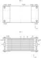
FIGS. 3 and4 are plan views illustrating the battery module ofFIG. 2 . -
FIG. 5 is a side view illustrating a battery module according to another embodiment of the present disclosure. -
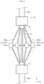
FIG. 6 is a view illustrating a pressure relief coupler applied to a battery module according to another embodiment of the present disclosure. - Hereinafter, preferred embodiments of the present disclosure will be described in detail with reference to the accompanying drawings. Prior to the description, it should be understood that the terms used in the specification and the appended claims should not be construed as limited to general and dictionary meanings, but interpreted based on the meanings and concepts corresponding to technical aspects of the present disclosure on the basis of the principle that the inventor is allowed to define terms appropriately for the best explanation. Therefore, the description proposed herein is just a preferable example for the purpose of illustrations only, not intended to limit the scope of the disclosure, so it should be understood that other equivalents and modifications could be made thereto without departing from the scope of the disclosure.
- Referring to
FIG. 2 , a battery module according to an embodiment of the present disclosure includes acell stack 10, anend plate 20, areinforcing plate 40, and afastening bolt 30. - The
cell stack 10 includes a plurality ofbattery cells 11. For example, a pouch-type battery cell may be used as thebattery cell 11. Although not shown inFIG. 2 , thebattery cell 11 includes a pair of electrode leads (not shown) extending to the outside of thebattery cell 11 in a longitudinal direction (direction parallel to an X-axis) of thebattery cell 11. The pair of electrode leads may be drawn in the same direction or opposite directions. The plurality ofbattery cells 11 are stacked in a vertical direction (direction parallel to a Z-axis). - The
cell stack 10 may further include aswelling absorbing pad 12 located betweenadjacent battery cells 11 and/or located at an outermost position in a stacked direction (direction parallel to the Z-axis) of thecell stack 10. Theswelling absorbing pad 12 may be compressed during swelling of thebattery cell 1 due to repeated charging and discharging to absorb volume expansion of thebattery cell 11. - The
end plate 20 includes afirst end plate 21 covering a top surface of thecell stack 10 and asecond end plate 22 covering a bottom surface of thecell stack 10. Thefirst end plate 21 and thesecond end plate 22 have areas corresponding to each other. Thefirst end plate 21 and thesecond end plate 22 have areas greater than that of thecell stack 10 to facilitate coupling using thefastening bolt 30. - Each of the
first end plate 21 and thesecond end plate 22 has sufficient stiffness to protect thecell stack 10 from external impact and suppress volume expansion due to swelling. Each of thefirst end plate 21 and thesecond end plate 22 may be formed of a metal material by considering such functions. - The
reinforcing plate 40 includes a firstupper reinforcing plate 41 and a secondupper reinforcing plate 42 located on thefirst end plate 21, and a firstlower reinforcing plate 43 and a secondlower reinforcing plate 44 located on thesecond end plate 22. - The first upper
reinforcing plate 41 extends from a side of thefirst end plate 21 in a longitudinal direction (parallel to the X-axis) of thefirst end plate 21 toward a central portion. The second upperreinforcing plate 42 extends from the other side of thefirst end plate 21 in the longitudinal direction of thefirst end plate 21 toward the central portion. The firstupper reinforcing plate 41 and the secondupper reinforcing plate 42 extend toward each other but are spaced apart from each other. - The first lower reinforcing
plate 43 extends from a side of thesecond end plate 22 in a longitudinal direction (direction parallel to the X-axis) of thesecond end plate 22 toward a central portion. The second lower reinforcingplate 44 extends from the other side of thesecond end plate 22 in the longitudinal direction of thesecond end plate 22 toward the central portion. The first lower reinforcingplate 43 and the second lower reinforcingplate 44 extend toward each other but are spaced apart from each other. - When the
battery cell 11 swells, a portion where volume expansion intensively occurs is a central portion of thebattery cell 11 in the longitudinal direction (direction parallel to the X-axis). Accordingly, each of theupper end plate 21 and thelower end plate 22 is subjected to intensive pressure at a central portion in the longitudinal direction (direction parallel to the X-axis). - The first
upper reinforcing plate 41 and the secondupper reinforcing plate 42 partially reinforce stiffness of theupper end plate 21, and thus, a strain of theupper end plate 21 due to swelling pressure is reduced. Likewise, the first lower reinforcingplate 43 and the second lower reinforcingplate 44 partially reinforce stiffness of thelower end plate 22, and thus, a strain of thelower end plate 22 due to swelling pressure is reduced. - Because the first
upper reinforcing plate 41 and the secondupper reinforcing plate 42 partially reinforce theupper end plate 21, bending stiffness of theupper end plate 21 may be effectively reinforced without significantly increasing a weight of the battery module. Also, because the firstupper reinforcing plate 41 and the secondupper reinforcing plate 42 are spaced apart from each other without being connected to each other, excessive suppression of volume expansion due to swelling may be prevented. Likewise, because the first lower reinforcingplate 43 and the second lower reinforcingplate 44 partially reinforce thelower end plate 22, bending stiffness of thelower end plate 22 may be effectively reinforced without significantly increasing a weight of the battery module. Also, because the first lower reinforcingplate 43 and the second lower reinforcingplate 44 are spaced apart from each other without being connected to each other, excessive suppression of volume expansion due to swelling may be prevented. - The
fastening bolt 30 includes afirst fastening bolt 31 located on a side of thecell stack 10 in a longitudinal direction (direction parallel to the X-axis) of thecell stack 10 and asecond fastening bolt 32 located on the other side of thecell stack 10 in the longitudinal direction of thecell stack 10. - The
first fastening bolt 31 passes through an end portion of each of the firstupper reinforcing plate 41, thefirst end plate 21, thesecond end plate 22, and the first lower reinforcingplate 43 in the longitudinal direction (direction parallel to the X-axis). Due to thefirst fastening bolt 31, theupper end plate 21 and thelower end plate 22 are closely fixed to thecell stack 10. Due to thefirst fastening bolt 31, the firstupper reinforcing plate 41 and the second lower reinforcingplate 43 are respectively closely fixed to theupper end plate 21 and thelower end plate 22. - The
second fastening bolt 32 passes through the other end portion of each of the secondupper reinforcing plate 42, thefirst end plate 21, thesecond end plate 2, and the second lower reinforcingplate 44 in the longitudinal direction (directions parallel to the X-axis). Due to thesecond fastening bolt 32, theupper end plate 21 and thelower end plate 22 are closely fixed to thecell stack 10. Due to thesecond fastening bolt 32, the secondupper reinforcing plate 42 and the second lower reinforcingplate 44 are respectively closely fixed to theupper end plate 21 and thelower end plate 22. - Referring to
FIGS. 2 and3 , a pair offirst fastening bolts 31 and a pair ofsecond fastening bolts 32 may be respectively provided on an end portion and the other end portion of the battery module in a width direction (direction parallel to a Y-axis) of the battery module. In this case, a pair of first upper reinforcingplates 41 and a pair of first lower reinforcingplates 43 may be respectively provided on an end portion and the other end portion of the battery module in the width direction of the battery module. Likewise, a pair of second upper reinforcingplates 42 and a pair of second lower reinforcingplates 44 may be respectively provided on an end portion and the other end portion of the battery module in the width direction of the battery module. - Referring to
FIGS. 2 and4 , unlike inFIG. 3 , one firstupper reinforcing plate 41 and one first lower reinforcingplate 43 may be provided on an end portion of the battery module in a longitudinal direction of the battery module. In this case, each of the firstupper reinforcing plate 41 and the first lower reinforcingplate 43 extends from an end portion toward the other end portion of the battery module in a width direction of the battery module, and theupper end plate 21 and thelower end plate 22 are fastened by a pair offirst fastening bolts 31. - Likewise, one second
upper reinforcing plate 42 and one second lower reinforcingplate 44 may be provided on the other end portion of the battery module in the longitudinal direction of the battery module. In this case, each of the secondupper reinforcing plate 42 and the second lower reinforcingplate 44 extends from an end portion toward the other end portion of the battery module in the width direction of the battery module, and theupper end plate 21 and thelower end plate 22 are fastened by a pair ofsecond fastening bolts 32. - Referring to
FIGS. 5 and6 , each of thefirst fastening bolt 31 and thesecond fastening bolt 32 may include anupper bolt 30a and alower bolt 30b that are spaced apart from each other. In this case, the battery module may further include apressure relief coupler 50 that connects theupper bolt 30a to thelower bolt 30b. - The
pressure relief coupler 50 includes a firstmain hinge 51 coupled to theupper bolt 30a, a secondmain hinge 52 coupled to thelower bolt 30b, and afirst connection bar 53 fastened between the firstmain hinge 51 and the secondmain hinge 52. Thefirst connection bar 53 prevents pressure applied to thebattery cell 11 from excessively increasing due to theend plate 20 whose bending stiffness is increased according to the application of the reinforcingplate 40. - To perform this function, the
first connection bar 53 has a bar shape having a smaller thickness than theupper bolt 30a and thelower bolt 30b constituting thefastening bolt 30. Theupper bolt 30a and thelower bolt 30b, and thefirst connection bar 53 are all formed of a metal material. Theupper bolt 30a and thelower bolt 30b having a relative large thickness hardly elongate even when a force in a vertical direction (direction parallel to the Z-axis) is applied to theend plate 20 due to swelling pressure. In contrast, when a large force is applied to theend plate 20, thefirst connection bar 53 having a relatively small thickness may elongate by a certain length to reduce pressure applied to thecell stack 10. When pressure applied to thecell stack 10 is too high, pores of a separator in thebattery cell 11 may be blocked, and thus, the performance of thebattery cell 11 nay be degraded. Thepressure relief coupler 50 corresponds to an element applied to prevent performance degradation of thebattery cell 11. - The
pressure relief coupler 50 may further include at least a pair of firstsub-connection bar assemblies 54 provided on a side and the other side of thefirst connection bar 53 and hinged to the firstmain hinge 51 and the secondmain hinge 52. - The first
sub-connection bar assembly 54 includes a pair of firstsub-connection bars main hinge 51 and the secondmain hinge 52, and a first sub-hinge 54c hinged between the pair of firstsub-connection bars - Each of the pair of first
sub-connection bars upper bolt 30a and thelower bolt 30b. A sum of lengths of the pair of firstsub-connection bars first connection bar 53. Accordingly, as thefirst connection bar 53 elongates according to an increase in swelling pressure, the first sub-hinge 54c moves toward thefirst connection bar 53 in an arrow direction ofFIG. 6 . When the first sub-hinge 54c reaches a position where the first sub-hinge 54c may no longer move, a tensile force according to swelling pressure is applied to thefirst sub-connection bars 54a, 564b, and thus, thefirst sub-connection bars first connection bar 53, thereby reducing swelling pressure. - The
pressure relief coupler 50 may further include at least a pair of secondsub-connection bar assemblies 55 provided on a side and the other side of thefirst connection bar 53 and located more outside than the firstsub-connection bar assembly 54. The pair of secondsub-connection bar assemblies 55 are hinged to the firstmain hinge 51 and the secondmain hinge 52. - The second
sub-connection bar assembly 55 includes a pair of secondsub-connection bars main hinge 51 and the secondmain hinge 52, and a second sub-hinge 55c hinged between the pair of secondsub-connection bars - Each of the pair of second
sub-connection bars upper bolt 30a and thelower bolt 30b. A sum of lengths of the pair of secondsub-connection bars sub-connection bars first sub-connection bars sub-connection bar assembly 54 in an arrow direction ofFIG. 6 . When the second sub-hinge 55c reaches a position where the second sub-hinge 55c may no longer move, a tensile force according to swelling pressure is applied to thesecond sub-connection bars second sub-connection bars first connection bar 53 and thefirst sub-connection bars - Although a case where the battery module according to an embodiment of the present disclosure includes the first
sub-connection bar assembly 54 and a case where the battery module includes the firstsub-connection bar assembly 54 and the secondsub-connection bar assembly 55 are shown in the drawings, the present disclosure is not limited thereto. That is, the battery module according to an embodiment of the present disclosure may further include an additional sub-connection bar assembly in addition to the firstsub-connection bar assembly 54 and the secondsub-connection bar assembly 55. - A battery pack according to an embodiment of the present disclosure includes the battery module according to an embodiment of the present disclosure as described above. Also, a vehicle according to an embodiment of the present disclosure includes the battery module according to an embodiment of the present disclosure as described above.
- Although the embodiments of the present disclosure have been illustrated and described above, the present disclosure is not limited to the above-described specific embodiments. Various modified embodiments may be made by one of ordinary skill in the art without departing from the scope of the present disclosure as claimed in the claims.
Claims (15)
- A battery module comprising:a cell stack comprising a plurality of battery cells;a first end plate and a second end plate respectively covering a top surface and a bottom surface of the cell stack;a first upper reinforcing plate and a second upper reinforcing plate located on the first end plate and respectively extending from a side and the other side of the first end plate in a longitudinal direction of the first end plate toward a central portion of the first end plate;a first lower reinforcing plate and a second lower reinforcing plate located on the second end plate and respectively extending from a side and the other side of the second end plate in a longitudinal direction of the second end plate toward a central portion of the second end plate;a first fastening bolt located on a side of the cell stack in a longitudinal direction of the cell stack, and passing through the first upper reinforcing plate, the first end plate, the second end plate, and the first lower reinforcing plate; anda second fastening bolt located on the other side of the cell stack in the longitudinal direction of the cell stack, and passing through the second upper reinforcing plate, the first end plate, the second end plate, and the second lower reinforcing plate.
- The battery module according to claim 1, wherein the first upper reinforcing plate and the second upper reinforcing plate extend toward each other but are spaced apart from each other, and
the first lower reinforcing plate and the second lower reinforcing plate extend toward each other but are spaced apart from each other. - The battery module according to claim 1, wherein a pair of first fastening bolts and a pair of second fastening bolts are respectively provided on an end portion and the other end portion of the battery module in a width direction of the battery module.
- The battery module according to claim 3, wherein a pair of first upper reinforcing plates and a pair of first lower reinforcing plates are respectively provided on an end portion and the other end portion of the battery module in the width direction of the battery module, and
a pair of second upper reinforcing plates and a pair of second lower reinforcing plates are respectively provided on an end portion and the other end portion of the battery module in the width direction of the battery module. - The battery module according to claim 3, wherein the first upper reinforcing plate and the first lower reinforcing plate are respectively fastened to the upper end plate and the lower end plate by a pair of first fastening bolts, and
the second upper reinforcing plate and the second lower reinforcing plate are respectively fastened to the upper end plate and the lower end plate by a pair of second fastening bolts. - The battery module according to claim 1, wherein each of the first fastening bolt and the second fastening bolt comprises an upper bolt and a lower bolt that are spaced apart from each other,
wherein the battery module further comprises a pressure relief coupler connecting the upper bolt to the lower bolt. - The battery module according to claim 6, wherein the pressure relief coupler comprises:a first main hinge coupled to the upper bolt;a second main hinge coupled to the lower bolt; anda first connection bar fastened between the first main hinge and the second main hinge.
- The battery module according to claim 7, wherein the pressure relief coupler further comprises a pair of first sub-connection bar assemblies provided on a side and the other side of the first connection bar respectively, and hinged to the first main hinge and the second main hinge.
- The battery module according to claim 8, wherein each of the pair of first sub-connection bar assemblies comprises:a pair of first sub-connection bars respectively hinged to the first main hinge and the second main hinge; anda first sub-hinge hinged between the pair of first sub-connection bars.
- The battery module according to claim 9, wherein a sum of lengths of the pair of first sub-connection bars is greater than a length of the first connection bar.
- The battery module according to claim 10, wherein the pressure relief coupler further comprises a pair of second sub-connection bar assemblies provided on a side and the other side of the first connection bar, located more outside the first sub-connection bar assembly, and hinged to the first main hinge and the second main hinge.
- The battery module according to claim 11, wherein each of the pair of second sub-connection bar assemblies comprises:a pair of second sub-connection bars respectively hinged to the first main hinge and the second main hinge; anda second sub-hinge hinged between the pair of second sub-connection bars.
- The battery module according to claim 12, wherein a sum of lengths of the pair of second sub-connection bars is greater than a sum of lengths of the pair of first sub-connection bars.
- A battery pack comprising the battery module according to any one of claims 1 through 13.
- A vehicle comprising the battery module according to any one of claims 1 through 13.
Applications Claiming Priority (2)
| Application Number | Priority Date | Filing Date | Title |
|---|---|---|---|
| KR1020200186475A KR102806311B1 (en) | 2020-12-29 | 2020-12-29 | A battery module having a structure capable of absorbing swelling, and a battery pack and vehicle including the same |
| PCT/KR2021/019893 WO2022145909A1 (en) | 2020-12-29 | 2021-12-24 | Battery module having structure capable of absorbing swelling, and battery pack and vehicle comprising same |
Publications (2)
| Publication Number | Publication Date |
|---|---|
| EP4167364A1 true EP4167364A1 (en) | 2023-04-19 |
| EP4167364A4 EP4167364A4 (en) | 2024-01-24 |
Family
ID=82259788
Family Applications (1)
| Application Number | Title | Priority Date | Filing Date |
|---|---|---|---|
| EP21915707.0A Pending EP4167364A4 (en) | 2020-12-29 | 2021-12-24 | BATTERY MODULE WITH STRUCTURE FOR ABSORPTION OF SWELLING AS WELL AS BATTERY PACK AND VEHICLE THEREOF |
Country Status (6)
| Country | Link |
|---|---|
| US (1) | US12614801B2 (en) |
| EP (1) | EP4167364A4 (en) |
| JP (1) | JP7566043B2 (en) |
| KR (1) | KR102806311B1 (en) |
| CN (1) | CN115803946A (en) |
| WO (1) | WO2022145909A1 (en) |
Families Citing this family (2)
| Publication number | Priority date | Publication date | Assignee | Title |
|---|---|---|---|---|
| US20240250371A1 (en) * | 2023-01-25 | 2024-07-25 | Samsung Sdi Co., Ltd. | Battery pack |
| IT202300027171A1 (en) * | 2023-12-19 | 2025-06-19 | Ferrari Spa | BATTERY PACK FOR AN ELECTRIC-POWERED ROAD VEHICLE AND METHOD OF COMPENSATION FOR THE CHANGE IN THICKNESS OF AN ELECTROCHEMICAL CELL FOR SUCH BATTERY PACK |
Family Cites Families (22)
| Publication number | Priority date | Publication date | Assignee | Title |
|---|---|---|---|---|
| JP3594023B2 (en) | 2002-07-30 | 2004-11-24 | 日産自動車株式会社 | Battery module |
| JP3972884B2 (en) | 2003-10-10 | 2007-09-05 | 日産自動車株式会社 | Assembled battery |
| US7625665B2 (en) | 2004-11-30 | 2009-12-01 | Samsung Sdi Co., Ltd. | Secondary battery module and end-plate used in the same |
| KR100612393B1 (en) * | 2004-11-30 | 2006-08-16 | 삼성에스디아이 주식회사 | Secondary battery module |
| KR100590049B1 (en) | 2004-11-30 | 2006-06-14 | 삼성에스디아이 주식회사 | Secondary battery module and unit cell fixing plate |
| JP4772614B2 (en) | 2005-07-29 | 2011-09-14 | 三星エスディアイ株式会社 | Battery module |
| KR100684762B1 (en) * | 2005-07-29 | 2007-02-20 | 삼성에스디아이 주식회사 | Secondary battery module and unit cell fixing plate |
| KR101104151B1 (en) | 2007-06-28 | 2012-01-13 | 주식회사 엘지화학 | Apparatus including plate reinforcement members |
| JP5481796B2 (en) | 2008-03-27 | 2014-04-23 | 株式会社デンソー | Battery equipment module and battery pack having battery stack restraining means |
| KR101224496B1 (en) | 2010-02-04 | 2013-01-21 | 주식회사 엘지화학 | Battery Pack Having Reinforcement Member |
| DE102010012936A1 (en) | 2010-03-26 | 2011-09-29 | Daimler Ag | Cell network with a predefinable number of parallel and / or series electrically interconnected single cells |
| JP5433669B2 (en) | 2011-11-30 | 2014-03-05 | 三菱重工業株式会社 | Battery module and battery system |
| KR20130123762A (en) * | 2012-05-03 | 2013-11-13 | 주식회사 엘지화학 | Secondary battery assembly, pressing apparatus applied for it |
| CN103594745A (en) * | 2013-11-13 | 2014-02-19 | 福州大学 | Method and device for improving performance of lithium ion battery |
| CN204407383U (en) * | 2014-12-23 | 2015-06-17 | 山东精工电子科技有限公司 | A kind of flexible-packed battery group device |
| EP3285310B1 (en) * | 2015-04-16 | 2020-03-11 | Panasonic Intellectual Property Management Co., Ltd. | Assembled battery |
| KR101806995B1 (en) * | 2015-05-18 | 2017-12-08 | 주식회사 엘지화학 | Battery pack |
| KR102488450B1 (en) * | 2018-03-20 | 2023-01-12 | 주식회사 엘지에너지솔루션 | Pouch type secondary battery to which a swelling prevention structure is applied and battery module including the same |
| JP7200223B2 (en) * | 2018-03-30 | 2023-01-06 | 三洋電機株式会社 | Power supply device and vehicle equipped with it |
| JP7070279B2 (en) * | 2018-09-20 | 2022-05-18 | 株式会社豊田自動織機 | Power storage module |
| DE102019205777A1 (en) * | 2019-04-23 | 2020-10-29 | Audi Ag | Clamping device for a battery module, battery module and motor vehicle |
| KR102776217B1 (en) * | 2019-05-03 | 2025-03-04 | 현대자동차주식회사 | Battery module for vehicle |
-
2020
- 2020-12-29 KR KR1020200186475A patent/KR102806311B1/en active Active
-
2021
- 2021-12-24 US US18/032,143 patent/US12614801B2/en active Active
- 2021-12-24 JP JP2022572783A patent/JP7566043B2/en active Active
- 2021-12-24 EP EP21915707.0A patent/EP4167364A4/en active Pending
- 2021-12-24 CN CN202180037261.9A patent/CN115803946A/en active Pending
- 2021-12-24 WO PCT/KR2021/019893 patent/WO2022145909A1/en not_active Ceased
Also Published As
| Publication number | Publication date |
|---|---|
| WO2022145909A1 (en) | 2022-07-07 |
| JP7566043B2 (en) | 2024-10-11 |
| KR20220094838A (en) | 2022-07-06 |
| US12614801B2 (en) | 2026-04-28 |
| CN115803946A (en) | 2023-03-14 |
| US20230395917A1 (en) | 2023-12-07 |
| JP2023528791A (en) | 2023-07-06 |
| EP4167364A4 (en) | 2024-01-24 |
| KR102806311B1 (en) | 2025-05-09 |
Similar Documents
| Publication | Publication Date | Title |
|---|---|---|
| RU2692465C2 (en) | Battery housing (embodiments) | |
| JP7644115B2 (en) | Battery packs and electric vehicles | |
| US11152660B2 (en) | Device for accommodating at least one energy module for a motor vehicle | |
| US12614801B2 (en) | Battery module having structure capable of absorbing swelling, and battery pack and vehicle comprising same | |
| KR102922367B1 (en) | Battery mounting sturcure for vehicle | |
| US11245155B2 (en) | Battery module for a vehicle | |
| EP4365065A1 (en) | Side sill for vehicle | |
| US20240286685A1 (en) | Side sill for vehicle | |
| EP4365064A1 (en) | Side sill for vehicle | |
| WO2023090112A1 (en) | Body lower structure and side sill structure for automotive vehicle | |
| EP4181294B1 (en) | Battery module having structure enabling uniform pressure to be applied during swelling, and battery pack and vehicle comprising same | |
| JP7394174B1 (en) | Vehicle side structure | |
| JP7033255B2 (en) | Batteries assembled | |
| CN121035484A (en) | Battery devices and electrical equipment | |
| JP6994677B2 (en) | Batteries assembled | |
| US20240243404A1 (en) | Side reinforcing structure of a battery case and a vehicle including the same | |
| JP7394173B1 (en) | Vehicle side structure | |
| EP4640526A1 (en) | Frame for electric vehicle | |
| KR20240093094A (en) | Vehicle chassis frame | |
| KR100649211B1 (en) | Secondary battery module | |
| KR102922368B1 (en) | Battery case for vehicle | |
| KR100257718B1 (en) | Fender | |
| CN223230451U (en) | Battery package shell | |
| CN115515809A (en) | Vehicle structure with accumulator | |
| CN224110400U (en) | Battery devices and electrical equipment |
Legal Events
| Date | Code | Title | Description |
|---|---|---|---|
| STAA | Information on the status of an ep patent application or granted ep patent |
Free format text: STATUS: THE INTERNATIONAL PUBLICATION HAS BEEN MADE |
|
| PUAI | Public reference made under article 153(3) epc to a published international application that has entered the european phase |
Free format text: ORIGINAL CODE: 0009012 |
|
| STAA | Information on the status of an ep patent application or granted ep patent |
Free format text: STATUS: REQUEST FOR EXAMINATION WAS MADE |
|
| 17P | Request for examination filed |
Effective date: 20230113 |
|
| AK | Designated contracting states |
Kind code of ref document: A1 Designated state(s): AL AT BE BG CH CY CZ DE DK EE ES FI FR GB GR HR HU IE IS IT LI LT LU LV MC MK MT NL NO PL PT RO RS SE SI SK SM TR |
|
| REG | Reference to a national code |
Ref country code: DE Ref legal event code: R079 Free format text: PREVIOUS MAIN CLASS: H01M0050242000 Ipc: H01M0010040000 |
|
| A4 | Supplementary search report drawn up and despatched |
Effective date: 20231222 |
|
| RIC1 | Information provided on ipc code assigned before grant |
Ipc: H01M 50/264 20210101ALI20231218BHEP Ipc: H01M 50/262 20210101ALI20231218BHEP Ipc: H01M 50/249 20210101ALI20231218BHEP Ipc: H01M 50/242 20210101ALI20231218BHEP Ipc: H01M 50/209 20210101ALI20231218BHEP Ipc: H01M 10/04 20060101AFI20231218BHEP |
|
| DAV | Request for validation of the european patent (deleted) | ||
| DAX | Request for extension of the european patent (deleted) |