EP4167349A1 - Battery module having cooling structure using insulating oil, and battery pack and vehicle comprising same - Google Patents
Battery module having cooling structure using insulating oil, and battery pack and vehicle comprising same Download PDFInfo
- Publication number
- EP4167349A1 EP4167349A1 EP21892298.7A EP21892298A EP4167349A1 EP 4167349 A1 EP4167349 A1 EP 4167349A1 EP 21892298 A EP21892298 A EP 21892298A EP 4167349 A1 EP4167349 A1 EP 4167349A1
- Authority
- EP
- European Patent Office
- Prior art keywords
- bus bar
- spacer
- bar frame
- battery
- module
- Prior art date
- Legal status (The legal status is an assumption and is not a legal conclusion. Google has not performed a legal analysis and makes no representation as to the accuracy of the status listed.)
- Granted
Links
Images



Classifications
-
- H—ELECTRICITY
- H01—ELECTRIC ELEMENTS
- H01M—PROCESSES OR MEANS, e.g. BATTERIES, FOR THE DIRECT CONVERSION OF CHEMICAL ENERGY INTO ELECTRICAL ENERGY
- H01M10/00—Secondary cells; Manufacture thereof
- H01M10/60—Heating or cooling; Temperature control
- H01M10/65—Means for temperature control structurally associated with the cells
- H01M10/655—Solid structures for heat exchange or heat conduction
- H01M10/6556—Solid parts with flow channel passages or pipes for heat exchange
-
- H—ELECTRICITY
- H01—ELECTRIC ELEMENTS
- H01M—PROCESSES OR MEANS, e.g. BATTERIES, FOR THE DIRECT CONVERSION OF CHEMICAL ENERGY INTO ELECTRICAL ENERGY
- H01M10/00—Secondary cells; Manufacture thereof
- H01M10/60—Heating or cooling; Temperature control
- H01M10/61—Types of temperature control
-
- H—ELECTRICITY
- H01—ELECTRIC ELEMENTS
- H01M—PROCESSES OR MEANS, e.g. BATTERIES, FOR THE DIRECT CONVERSION OF CHEMICAL ENERGY INTO ELECTRICAL ENERGY
- H01M10/00—Secondary cells; Manufacture thereof
- H01M10/60—Heating or cooling; Temperature control
- H01M10/61—Types of temperature control
- H01M10/613—Cooling or keeping cold
-
- H—ELECTRICITY
- H01—ELECTRIC ELEMENTS
- H01M—PROCESSES OR MEANS, e.g. BATTERIES, FOR THE DIRECT CONVERSION OF CHEMICAL ENERGY INTO ELECTRICAL ENERGY
- H01M10/00—Secondary cells; Manufacture thereof
- H01M10/60—Heating or cooling; Temperature control
- H01M10/62—Heating or cooling; Temperature control specially adapted for specific applications
- H01M10/625—Vehicles
-
- H—ELECTRICITY
- H01—ELECTRIC ELEMENTS
- H01M—PROCESSES OR MEANS, e.g. BATTERIES, FOR THE DIRECT CONVERSION OF CHEMICAL ENERGY INTO ELECTRICAL ENERGY
- H01M10/00—Secondary cells; Manufacture thereof
- H01M10/60—Heating or cooling; Temperature control
- H01M10/64—Heating or cooling; Temperature control characterised by the shape of the cells
- H01M10/647—Prismatic or flat cells, e.g. pouch cells
-
- H—ELECTRICITY
- H01—ELECTRIC ELEMENTS
- H01M—PROCESSES OR MEANS, e.g. BATTERIES, FOR THE DIRECT CONVERSION OF CHEMICAL ENERGY INTO ELECTRICAL ENERGY
- H01M10/00—Secondary cells; Manufacture thereof
- H01M10/60—Heating or cooling; Temperature control
- H01M10/65—Means for temperature control structurally associated with the cells
- H01M10/655—Solid structures for heat exchange or heat conduction
- H01M10/6553—Terminals or leads
-
- H—ELECTRICITY
- H01—ELECTRIC ELEMENTS
- H01M—PROCESSES OR MEANS, e.g. BATTERIES, FOR THE DIRECT CONVERSION OF CHEMICAL ENERGY INTO ELECTRICAL ENERGY
- H01M10/00—Secondary cells; Manufacture thereof
- H01M10/60—Heating or cooling; Temperature control
- H01M10/65—Means for temperature control structurally associated with the cells
- H01M10/655—Solid structures for heat exchange or heat conduction
- H01M10/6554—Rods or plates
- H01M10/6555—Rods or plates arranged between the cells
-
- H—ELECTRICITY
- H01—ELECTRIC ELEMENTS
- H01M—PROCESSES OR MEANS, e.g. BATTERIES, FOR THE DIRECT CONVERSION OF CHEMICAL ENERGY INTO ELECTRICAL ENERGY
- H01M10/00—Secondary cells; Manufacture thereof
- H01M10/60—Heating or cooling; Temperature control
- H01M10/65—Means for temperature control structurally associated with the cells
- H01M10/656—Means for temperature control structurally associated with the cells characterised by the type of heat-exchange fluid
- H01M10/6567—Liquids
-
- H—ELECTRICITY
- H01—ELECTRIC ELEMENTS
- H01M—PROCESSES OR MEANS, e.g. BATTERIES, FOR THE DIRECT CONVERSION OF CHEMICAL ENERGY INTO ELECTRICAL ENERGY
- H01M50/00—Constructional details or processes of manufacture of the non-active parts of electrochemical cells other than fuel cells, e.g. hybrid cells
- H01M50/10—Primary casings; Jackets or wrappings
- H01M50/183—Sealing members
- H01M50/186—Sealing members characterised by the disposition of the sealing members
-
- H—ELECTRICITY
- H01—ELECTRIC ELEMENTS
- H01M—PROCESSES OR MEANS, e.g. BATTERIES, FOR THE DIRECT CONVERSION OF CHEMICAL ENERGY INTO ELECTRICAL ENERGY
- H01M50/00—Constructional details or processes of manufacture of the non-active parts of electrochemical cells other than fuel cells, e.g. hybrid cells
- H01M50/20—Mountings; Secondary casings or frames; Racks, modules or packs; Suspension devices; Shock absorbers; Transport or carrying devices; Holders
-
- H—ELECTRICITY
- H01—ELECTRIC ELEMENTS
- H01M—PROCESSES OR MEANS, e.g. BATTERIES, FOR THE DIRECT CONVERSION OF CHEMICAL ENERGY INTO ELECTRICAL ENERGY
- H01M50/00—Constructional details or processes of manufacture of the non-active parts of electrochemical cells other than fuel cells, e.g. hybrid cells
- H01M50/20—Mountings; Secondary casings or frames; Racks, modules or packs; Suspension devices; Shock absorbers; Transport or carrying devices; Holders
- H01M50/204—Racks, modules or packs for multiple batteries or multiple cells
- H01M50/207—Racks, modules or packs for multiple batteries or multiple cells characterised by their shape
- H01M50/211—Racks, modules or packs for multiple batteries or multiple cells characterised by their shape adapted for pouch cells
-
- H—ELECTRICITY
- H01—ELECTRIC ELEMENTS
- H01M—PROCESSES OR MEANS, e.g. BATTERIES, FOR THE DIRECT CONVERSION OF CHEMICAL ENERGY INTO ELECTRICAL ENERGY
- H01M50/00—Constructional details or processes of manufacture of the non-active parts of electrochemical cells other than fuel cells, e.g. hybrid cells
- H01M50/50—Current conducting connections for cells or batteries
-
- H—ELECTRICITY
- H01—ELECTRIC ELEMENTS
- H01M—PROCESSES OR MEANS, e.g. BATTERIES, FOR THE DIRECT CONVERSION OF CHEMICAL ENERGY INTO ELECTRICAL ENERGY
- H01M50/00—Constructional details or processes of manufacture of the non-active parts of electrochemical cells other than fuel cells, e.g. hybrid cells
- H01M50/50—Current conducting connections for cells or batteries
- H01M50/502—Interconnectors for connecting terminals of adjacent batteries; Interconnectors for connecting cells outside a battery casing
-
- H—ELECTRICITY
- H01—ELECTRIC ELEMENTS
- H01M—PROCESSES OR MEANS, e.g. BATTERIES, FOR THE DIRECT CONVERSION OF CHEMICAL ENERGY INTO ELECTRICAL ENERGY
- H01M50/00—Constructional details or processes of manufacture of the non-active parts of electrochemical cells other than fuel cells, e.g. hybrid cells
- H01M50/50—Current conducting connections for cells or batteries
- H01M50/502—Interconnectors for connecting terminals of adjacent batteries; Interconnectors for connecting cells outside a battery casing
- H01M50/503—Interconnectors for connecting terminals of adjacent batteries; Interconnectors for connecting cells outside a battery casing characterised by the shape of the interconnectors
-
- H—ELECTRICITY
- H01—ELECTRIC ELEMENTS
- H01M—PROCESSES OR MEANS, e.g. BATTERIES, FOR THE DIRECT CONVERSION OF CHEMICAL ENERGY INTO ELECTRICAL ENERGY
- H01M50/00—Constructional details or processes of manufacture of the non-active parts of electrochemical cells other than fuel cells, e.g. hybrid cells
- H01M50/50—Current conducting connections for cells or batteries
- H01M50/502—Interconnectors for connecting terminals of adjacent batteries; Interconnectors for connecting cells outside a battery casing
- H01M50/507—Interconnectors for connecting terminals of adjacent batteries; Interconnectors for connecting cells outside a battery casing comprising an arrangement of two or more busbars within a container structure, e.g. busbar modules
-
- H—ELECTRICITY
- H01—ELECTRIC ELEMENTS
- H01M—PROCESSES OR MEANS, e.g. BATTERIES, FOR THE DIRECT CONVERSION OF CHEMICAL ENERGY INTO ELECTRICAL ENERGY
- H01M2220/00—Batteries for particular applications
- H01M2220/20—Batteries in motive systems, e.g. vehicle, ship, plane
-
- Y—GENERAL TAGGING OF NEW TECHNOLOGICAL DEVELOPMENTS; GENERAL TAGGING OF CROSS-SECTIONAL TECHNOLOGIES SPANNING OVER SEVERAL SECTIONS OF THE IPC; TECHNICAL SUBJECTS COVERED BY FORMER USPC CROSS-REFERENCE ART COLLECTIONS [XRACs] AND DIGESTS
- Y02—TECHNOLOGIES OR APPLICATIONS FOR MITIGATION OR ADAPTATION AGAINST CLIMATE CHANGE
- Y02E—REDUCTION OF GREENHOUSE GAS [GHG] EMISSIONS, RELATED TO ENERGY GENERATION, TRANSMISSION OR DISTRIBUTION
- Y02E60/00—Enabling technologies; Technologies with a potential or indirect contribution to GHG emissions mitigation
- Y02E60/10—Energy storage using batteries
Definitions
- the present disclosure relates to a battery module having a cooling structure using insulating oil, and a battery pack and a vehicle including the battery module, and more particularly, to a battery module having a structure in which insulating oil introduced into a module housing and cooling a battery cell may flow through an inner space of a bus bar frame into a cell stack assembly, and a battery pack and a vehicle including the battery module.
- an airtight structure should be applied to various positions to prevent the insulating oil filled in the module housing from leaking to the outside of the module housing.
- an airtight structure should be applied to prevent leakage of oil at a coupling portion between the mono frame and an insulating plate and/or an end plate covering both opening portions of the mono frame.
- a high-potential terminal is usually exposed to the outside of the end plate and/or the insulating plate, and because a hole through which the high-potential terminal is exposed to the outside corresponds to a position where leakage of insulating oil is likely to occur, an airtight structure should also be applied to the position.
- the present disclosure is designed to solve the problems of the related art, and therefore the present disclosure is directed to allowing insulating oil for cooling of a battery module to directly contact a body of a battery cell to maximize cooling efficiency and effectively prevent leakage of insulating oil which is likely to occur in this insulating oil direct contact structure.
- a battery module including: a cell stack assembly including a plurality of battery cells and a plurality of fluid passage spacers located between adjacent battery cells; a front bus bar frame assembly including a module inlet through which insulating oil for cooling of the plurality of battery cells is supplied to the plurality of fluid passage spacers, the front bus bar frame assembly being coupled to a side of the cell stack assembly in a longitudinal direction of the cell stack assembly to electrically connect the plurality of battery cells; and a rear bus bar frame assembly including a module outlet through which insulating oil passing through the module inlet and the plurality of fluid passage spacers is discharged to outside, the rear bus bar frame assembly being coupled to the other side of the cell stack assembly in the longitudinal direction of the cell longitudinal direction of the cell stack assembly to electrically connect the plurality of battery cells.
- Each of the plurality of fluid passage spacers may include: a spacer body having an open central portion so that insulating oil flowing inside the fluid passage spacer contacts the battery cell; a spacer inlet formed on a side of the spacer body in a longitudinal direction of the spacer body and fastened to the front bus bar frame assembly; and a spacer outlet formed on the other side of the spacer body in the longitudinal direction of the spacer body and fastened to the rear bus bar frame assembly.
- a first gasket may be located at a contact interface between the spacer body and the battery cell.
- the fluid passage spacer may further include a plurality of insulating oil guides configured to connect an upper end of the spacer body to a lower of the spacer body and spaced apart from one another in the longitudinal direction of the spacer body.
- the front bus bar frame assembly may include: a front bus bar frame formed on a surface opposite to the module inlet and including a front frame fastening portion fastened to the spacer inlet; and a front bus bar provided on the front bus bar frame and coupled to electrode leads of the plurality of battery cells.
- the rear bus bar frame assembly may include: a rear bus bar frame formed on a surface opposite to the module outlet and including a rear frame fastening portion fastened to the spacer outlet; and a rear bus bar provided on the rear bus bar frame and coupled to electrode leads of the plurality of battery cells.
- a second gasket may be located between the front frame fastening portion and a coupling surface of the spacer inlet and between the rear frame fastening portion and a coupling surface of the spacer outlet.
- the battery module may further include a pair of side plates respectively covering a pair of battery cells located at both outermost positions in a stack direction of the cell stack assembly.
- Each of the pair of side plates may include a space in which insulating oil may flow, and both end portions of the side plate in a longitudinal direction of the side plate may be respectively coupled to the front frame fastening portion and the rear frame fastening portion.
- a battery pack and a vehicle including the battery module.
- insulating oil for cooling of a battery module may directly contact a body of a battery cell, thereby maximizing cooling efficiency.
- leakage of insulating oil flowing inside a module housing may be effectively prevented while an insulating oil direct contact structure is used.
- a battery module according to an embodiment of the present disclosure includes a cell stack assembly 100, a front bus bar frame assembly 200, and a rear bus bar frame assembly 300. Also, the battery module according to an embodiment of the present disclosure may further include a pair of side plates 400 in addition to the above elements.
- the cell stack assembly 100 includes a plurality of battery cells 110, and a plurality of fluid passage spacers 120 located between adjacent battery cells.
- the battery cell 110 may be a pouch-type battery cell including a cell body 111 and a pair of electrode leads 112 drawn out in opposite directions in a longitudinal direction (direction parallel to an X-axis) of the cell body 111.
- the fluid passage spacer 120 is fastened to the front bus bar frame assembly 200, and includes a fluid passage communicating with a fluid passage formed inside the front bus bar frame assembly 200.
- the fluid passage spacer 120 includes a spacer body 121, a spacer inlet 122a, and a spacer outlet 122b. Also, the fluid passage spacer 120 may further include a plurality of insulating oil guides 123 in addition to the above elements.
- the spacer body 121 has an open central portion so that insulating oil flowing through the fluid passage spacer 120 contacts the cell body 111 of the battery cell 110.
- the spacer inlet 122a is formed on a side of the spacer body 121 in a longitudinal direction of the spacer body 121 and is fastened to the front bus bar frame assembly 200.
- the spacer outlet 122b is formed on the other side of the spacer body 121 in the longitudinal direction of the spacer body 121 and fastened to the rear bus bar frame assembly 300. Due to this structure, insulating oil passing through the fluid passage formed inside the front bus bar frame assembly 200 is introduced through the spacer inlet 122a into the spacer body 121.
- the insulating oil introduced into the spacer body 121 contacts the cell body 111 to perform a cooling function, and then flows through the spacer outlet 122b into a fluid passage formed inside the rear bus bar frame assembly 300.
- the insulating oil guide 123 connects an upper end of the spacer body 121 to a lower end of the spacer body 121, and a plurality of insulating oil guides 123 are spaced apart from one another in the longitudinal direction (direction parallel to the X-axis) of the spacer body 121.
- the insulating oil guide 123 is located in an open space formed in the central portion of the spacer body 121.
- the insulating oil guide 123 is bent multiple times in a width direction (direction parallel to a Z-axis) of the fluid passage spacer 120, and due to this bent shape, includes a first contact area 123a contacting a first battery cell 110A located on a side of the fluid passage spacer 120 and a second contact area 123b contacting a second battery cell 110B located on the other side of the fluid passage spacer 120.
- the first contact area 123a and the second contact area 123b are alternately located in the width direction (direction parallel to the Z-axis) of the fluid passage spacer 120.
- a first guide fluid passage 120a through which insulating oil may flow is formed between the first contact area 123a and the second battery cell 110B, and a second guide fluid passage 120b through which insulating oil may flow is formed between the second contact area 123b and the first battery cell 110A.
- the first guide fluid passage 120a and the second guide fluid passage 120b are alternately formed in the width direction (direction parallel to the Z-axis) of the fluid passage spacer 120.
- the insulating oil guide 123 divides a part of the open space formed in the central portion of the spacer body 121 to form the first guide fluid passage 120a and the second guide fluid passage 120b. Accordingly, a uniform amount of insulating oil may flow in the entire width direction (direction parallel to the Z-axis) of the fluid passage spacer 120, and the flow of insulating oil may be guided so that a flow rate of the insulating oil is maintained at a certain level or more.
- a first gasket G1 may be located at a contact interface between the spacer body 121 and the cell body 111 of the battery cell 110.
- the front bus bar frame assembly 200 is coupled to a side of the cell stack assembly 100 in a longitudinal direction (direction parallel to the X-axis) of the cell stack assembly 100 to electrically connect the plurality of battery cells 110.
- the front bus bar frame assembly 200 includes a front bus bar frame 210 and a plurality of front bus bars 220. Also, the front bus bar frame assembly 200 may further include a pair of module terminals 230.
- the front bus bar frame 210 includes a module inlet P1 that is connected to an outer surface of the front bus bar frame 210 and through which insulating oil is injected, and a plurality of front frame fastening portions 211 formed on a surface opposite to the module inlet P21 and fastened to the spacer inlet 122a of the fluid passage spacer 120.
- a fluid passage through which insulating oil may flow is formed inside the front bus bar frame 210, and communicates with the module inlet P1. Also, the fluid passage formed inside the front bus bar frame 210 communicates with a hole formed in the front frame fastening portion 211. Accordingly, insulating oil introduced through the module inlet P1 into the front bus bar frame 210 passes through the fluid passage formed inside the front bus bar frame 210 and flows into the fluid passage spacer 120. That is, the front frame fastening portion 211 functions as a supply port for supplying insulating oil from the front bus bar frame 210 to the fluid passage spacer 120.
- the front frame fastening portion 211 protrudes from the front bus bar frame 210 toward the cell stack assembly 100, and a plurality of front frame fastening portions 211 are spaced apart from one another in a width direction (direction parallel to a Y-axis) of the battery module.
- the front frame fastening portions 211 are coupled to the plurality of fluid passage spacers 120 in a one-to-one manner.
- a second gasket G2 for preventing leakage of insulating oil may be located between the front frame fastening portion 211 and a coupling surface of the spacer inlet 122a. Also, in order to increase a fastening force and improve airtightness between the front frame fastening portion 211 and the spacer inlet 122a, a front insertion portion 211a protruding toward the cell stack assembly 100 and inserted into the spacer inlet 122a may be provided on the front frame fastening portion 211. When the front insertion portion 211a and the second gasket G2 are applied together, leakage preventing effect may be maximized.
- the front bus bar 220 is provided on the front bus bar frame 210, and is coupled to the electrode leads 112 of the plurality of battery cells 110 to electrically connect the battery cells 110.
- the electrode lead 112 passes through a slit and/or a hole formed in the front bus bar frame 210 and is coupled to the front bus bar 220.
- the pair of module terminals 230 are provided on the front bus bar frame 210, and are located on both sides of the front bus bar frame 210 in a longitudinal direction (direction parallel to the Y-axis) of the front bus bar frame 210.
- the pair of module terminals 230 function as high potential terminals by being connected to the electrode leads 112 of the battery cells 110 located at outermost positions from among the battery cells 110 constituting the cell stack assembly 100.
- the rear bus bar frame assembly 300 has a very similar structure to that of the front bus bar frame assembly 200 in outer appearance. However, when compared to the front bus bar frame assembly 200, the rear bus bar frame assembly 300 is different in that the rear bus bar frame assembly 300 is provided at the rear of the battery module, a module outlet P2, instead of the module inlet P1, is provided, and the module terminal 230 is not provided, but other elements are substantially the same.
- the rear bus bar frame assembly 300 includes a rear bus bar frame 310 and a plurality of rear bus bars (not shown).
- the rear bus bar is different in an installation position, but is substantially the same as the front bus bar 220 in terms of shape and function.
- the rear bus bar frame 310 includes the module outlet P2 that is connected to an outer surface of the rear bus bar frame 310 and through which insulating oil is discharged, and a plurality of rear frame fastening portions 311 formed on a surface opposite to the module outlet P2 and fastened to the spacer outlet 122b of the fluid passage spacer 120.
- a fluid passage through which insulating oil may flow is formed inside the rear bus bar frame 310, and communicates with the module outlet P2. Also, the fluid passage formed inside the rear bus bar frame 310 communicates with a hole formed in the rear frame fastening portion 311. Accordingly, insulating oil introduced through the spacer outlet 122b of the insulating oil spacer 120 into the rear bus bar frame 310 passes through the fluid passage formed inside the rear bus bar frame 310 and is discharged to the outside of the battery module through the module outlet P2. That is, the rear frame fastening portion 311 functions as a receiving port for receiving insulating oil passing through the fluid passage spacer 120 into the rear bus bar frame 310.
- the rear frame fastening portion 311 protrudes from the rear bus bar frame 310 toward the cell stack assembly 100, and a plurality of rear frame fastening portions 311 are spaced apart from one another in the width direction (direction parallel to the Y-axis) of the battery module.
- the rear frame fastening portions 311 are coupled to the plurality of the fluid passage spacers 120 in a one-to-one manner.
- the second gasket G2 for preventing leakage of insulating oil may be located between the rear frame fastening portion 311 and a coupling surface of the spacer outlet 122b. Also, in order to increase a fastening force and improve airtightness between the rear frame fastening portion 311 and the spacer outlet 122b, a rear insertion portion 311a protruding toward the cell stack assembly 100 and inserted into the spacer outlet 122b may be provided on the rear frame fastening portion 311. When the rear insertion portion 311a and the second gasket G2 are applied together, leakage preventing effect may be maximized.
- the pair of side plates 400 cover a pair of battery cells 110 located at both outermost positions of the cell stack assembly 100 in a stack direction (direction parallel to the Y-axis) of the cell stack assembly 100. Both end portions of the side plate 400 in a longitudinal direction (direction parallel to the X-axis) of the side plate 400 may be respectively fastened to the front bus bar frame assembly 200 and the rear bus bar frame assembly 300.
- the side plate 400 may have a space in which insulating oil may flow, and in order to communicate with the module inlet P1 and the module outlet P2, a side of the side plate 400 in the longitudinal direction (direction parallel to the X-axis) of the side plate 400 may be fastened to the spacer inlet 122a of the fluid passage spacer 120, and the other side of the side plate 400 in the longitudinal direction (direction parallel to the X-axis) of the side plate 400 may be fastened to the spacer outlet 122b of the fluid passage spacer 120.
- the side plates 400 may function as support plates supporting the cell stack assembly 100 from both sides in the stack direction (direction parallel to the Y-axis) of the cell stack assembly 100, and may perform a cooling function for the battery cells 110 located at outermost positions in the stack direction of the cell stack assembly 100.
- a battery module according to an embodiment of the present disclosure may allow insulating oil for cooling a battery module to directly contact a cell body, thereby maximizing cooling efficiency and effectively preventing leakage of insulating oil which is likely to occur in this insulating oil direct contact structure.
- a battery pack according to an embodiment of the present disclosure includes at least one battery module according to an embodiment of the present disclosure as described above.
- a vehicle according to an embodiment of the present disclosure includes the battery module or the battery pack according to an embodiment of the present disclosure as described above.
Landscapes
- Chemical & Material Sciences (AREA)
- Chemical Kinetics & Catalysis (AREA)
- Electrochemistry (AREA)
- General Chemical & Material Sciences (AREA)
- Engineering & Computer Science (AREA)
- Manufacturing & Machinery (AREA)
- Secondary Cells (AREA)
- Battery Mounting, Suspending (AREA)
- Connection Of Batteries Or Terminals (AREA)
Abstract
Description
- The present disclosure relates to a battery module having a cooling structure using insulating oil, and a battery pack and a vehicle including the battery module, and more particularly, to a battery module having a structure in which insulating oil introduced into a module housing and cooling a battery cell may flow through an inner space of a bus bar frame into a cell stack assembly, and a battery pack and a vehicle including the battery module.
- The present application claims priority to
Korean Patent Application No. 10-2020-0151349 filed on November 12, 2020 - In the case of a battery module using an indirect water cooling method using cooling water, because cooling water does not directly contact a battery cell but indirectly contacts the battery cell through a module housing in which the battery cell is accommodated, there is a limit to its cooling performance. Also, because a cooling device such as a separate heat sink should be provided outside the module housing to form a passage for cooling, a volume of the battery module is inevitably increased, which may cause loss in terms of energy density.
- In order to solve the problems of the indirect water cooling method, there is a need to develop a battery module having a cooling structure in which insulating oil for cooling may be directly introduced into a module housing and may directly contact a battery cell.
- In the case of a battery module having a direct cooling structure using insulating oil, it is important to develop a fluid passage structure for efficient cooling, but it is very important to maintain airtightness so that the insulating oil does not leak to the outside of a module housing and an end plate.
- In the case of a battery module having a structure in which insulating oil introduced into a module housing directly contacts a battery cell, an airtight structure should be applied to various positions to prevent the insulating oil filled in the module housing from leaking to the outside of the module housing.
- For example, in the case of a battery module to which a mono frame with both open sides in a longitudinal direction is applied, an airtight structure should be applied to prevent leakage of oil at a coupling portion between the mono frame and an insulating plate and/or an end plate covering both opening portions of the mono frame. Also, a high-potential terminal is usually exposed to the outside of the end plate and/or the insulating plate, and because a hole through which the high-potential terminal is exposed to the outside corresponds to a position where leakage of insulating oil is likely to occur, an airtight structure should also be applied to the position.
- As such, applying an airtight structure to various positions complicates a process of manufacturing a battery module, which leads to an increase in manufacturing cost. Accordingly, in order to omit the application of an airtight structure to a module housing or to simplify an airtight structure for a module housing, there is a need to develop a battery module in which an airtight structure is applied to components accommodated in the module housing.
- The present disclosure is designed to solve the problems of the related art, and therefore the present disclosure is directed to allowing insulating oil for cooling of a battery module to directly contact a body of a battery cell to maximize cooling efficiency and effectively prevent leakage of insulating oil which is likely to occur in this insulating oil direct contact structure.
- However, the technical purpose to be solved by the present disclosure is not limited to the above, and other objects not mentioned herein will be clearly understood by one of ordinary skill in the art from the following disclosure.
- In one aspect of the present disclosure, there is provided a battery module including: a cell stack assembly including a plurality of battery cells and a plurality of fluid passage spacers located between adjacent battery cells; a front bus bar frame assembly including a module inlet through which insulating oil for cooling of the plurality of battery cells is supplied to the plurality of fluid passage spacers, the front bus bar frame assembly being coupled to a side of the cell stack assembly in a longitudinal direction of the cell stack assembly to electrically connect the plurality of battery cells; and a rear bus bar frame assembly including a module outlet through which insulating oil passing through the module inlet and the plurality of fluid passage spacers is discharged to outside, the rear bus bar frame assembly being coupled to the other side of the cell stack assembly in the longitudinal direction of the cell longitudinal direction of the cell stack assembly to electrically connect the plurality of battery cells.
- Each of the plurality of fluid passage spacers may include: a spacer body having an open central portion so that insulating oil flowing inside the fluid passage spacer contacts the battery cell; a spacer inlet formed on a side of the spacer body in a longitudinal direction of the spacer body and fastened to the front bus bar frame assembly; and a spacer outlet formed on the other side of the spacer body in the longitudinal direction of the spacer body and fastened to the rear bus bar frame assembly.
- A first gasket may be located at a contact interface between the spacer body and the battery cell.
- The fluid passage spacer may further include a plurality of insulating oil guides configured to connect an upper end of the spacer body to a lower of the spacer body and spaced apart from one another in the longitudinal direction of the spacer body.
- The front bus bar frame assembly may include: a front bus bar frame formed on a surface opposite to the module inlet and including a front frame fastening portion fastened to the spacer inlet; and a front bus bar provided on the front bus bar frame and coupled to electrode leads of the plurality of battery cells.
- The rear bus bar frame assembly may include: a rear bus bar frame formed on a surface opposite to the module outlet and including a rear frame fastening portion fastened to the spacer outlet; and a rear bus bar provided on the rear bus bar frame and coupled to electrode leads of the plurality of battery cells.
- A second gasket may be located between the front frame fastening portion and a coupling surface of the spacer inlet and between the rear frame fastening portion and a coupling surface of the spacer outlet.
- The battery module may further include a pair of side plates respectively covering a pair of battery cells located at both outermost positions in a stack direction of the cell stack assembly.
- Each of the pair of side plates may include a space in which insulating oil may flow, and both end portions of the side plate in a longitudinal direction of the side plate may be respectively coupled to the front frame fastening portion and the rear frame fastening portion.
- In another aspect of the present disclosure, there are also provided a battery pack and a vehicle including the battery module.
- According to an aspect of the present disclosure, insulating oil for cooling of a battery module may directly contact a body of a battery cell, thereby maximizing cooling efficiency.
- Also, according to another aspect of the present disclosure, leakage of insulating oil flowing inside a module housing may be effectively prevented while an insulating oil direct contact structure is used.
- The accompanying drawings illustrate a preferred embodiment of the present disclosure and together with the foregoing disclosure, serve to provide further understanding of the technical features of the present disclosure, and thus, the present disclosure is not construed as being limited to the drawing.
-
FIG. 1 is an assembled perspective view illustrating a battery module according to an embodiment of the present disclosure. -
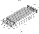
FIG. 2 is an exploded perspective view illustrating a battery module according to an embodiment of the present disclosure. -
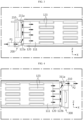
FIGS. 3 and 4 are cross-sectional views illustrating a flow of insulating oil for cooling, taken along line Y-Y' ofFIG. 1 . -
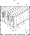
FIG. 5 is a partial enlarged view illustrating a cell stack assembly according to the present disclosure. -
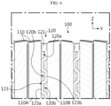
FIG. 6 is a partial cross-sectional view taken along line X-X' ofFIG. 1 . -
FIG. 7 is a view illustrating a front bus bar frame assembly (rear bus bar frame assembly) according to the present disclosure. -
FIG. 8 is a cross-sectional view illustrating an internal fluid passage of a front bus bar frame assembly according to the present disclosure. - Hereinafter, preferred embodiments of the present disclosure will be described in detail with reference to the accompanying drawings. Prior to the description, it should be understood that the terms used in the specification and the appended claims should not be construed as limited to general and dictionary meanings, but interpreted based on the meanings and concepts corresponding to technical aspects of the present disclosure on the basis of the principle that the inventor is allowed to define terms appropriately for the best explanation. Therefore, the description proposed herein is just a preferable example for the purpose of illustrations only, not intended to limit the scope of the disclosure, so it should be understood that other equivalents and modifications could be made thereto without departing from the scope of the disclosure.
- First, referring to
FIGS. 1 through 5 , a battery module according to an embodiment of the present disclosure includes acell stack assembly 100, a front busbar frame assembly 200, and a rear busbar frame assembly 300. Also, the battery module according to an embodiment of the present disclosure may further include a pair ofside plates 400 in addition to the above elements. - The
cell stack assembly 100 includes a plurality ofbattery cells 110, and a plurality offluid passage spacers 120 located between adjacent battery cells. - The
battery cell 110 may be a pouch-type battery cell including acell body 111 and a pair of electrode leads 112 drawn out in opposite directions in a longitudinal direction (direction parallel to an X-axis) of thecell body 111. - The
fluid passage spacer 120 is fastened to the front busbar frame assembly 200, and includes a fluid passage communicating with a fluid passage formed inside the front busbar frame assembly 200. Thefluid passage spacer 120 includes aspacer body 121, aspacer inlet 122a, and aspacer outlet 122b. Also, thefluid passage spacer 120 may further include a plurality ofinsulating oil guides 123 in addition to the above elements. - The
spacer body 121 has an open central portion so that insulating oil flowing through thefluid passage spacer 120 contacts thecell body 111 of thebattery cell 110. Thespacer inlet 122a is formed on a side of thespacer body 121 in a longitudinal direction of thespacer body 121 and is fastened to the front busbar frame assembly 200. Thespacer outlet 122b is formed on the other side of thespacer body 121 in the longitudinal direction of thespacer body 121 and fastened to the rear busbar frame assembly 300. Due to this structure, insulating oil passing through the fluid passage formed inside the front busbar frame assembly 200 is introduced through thespacer inlet 122a into thespacer body 121. The insulating oil introduced into thespacer body 121 contacts thecell body 111 to perform a cooling function, and then flows through thespacer outlet 122b into a fluid passage formed inside the rear busbar frame assembly 300. - Referring to
FIGS. 5 and6 , theinsulating oil guide 123 connects an upper end of thespacer body 121 to a lower end of thespacer body 121, and a plurality ofinsulating oil guides 123 are spaced apart from one another in the longitudinal direction (direction parallel to the X-axis) of thespacer body 121. - The
insulating oil guide 123 is located in an open space formed in the central portion of thespacer body 121. Theinsulating oil guide 123 is bent multiple times in a width direction (direction parallel to a Z-axis) of thefluid passage spacer 120, and due to this bent shape, includes afirst contact area 123a contacting afirst battery cell 110A located on a side of thefluid passage spacer 120 and asecond contact area 123b contacting asecond battery cell 110B located on the other side of thefluid passage spacer 120. Thefirst contact area 123a and thesecond contact area 123b are alternately located in the width direction (direction parallel to the Z-axis) of thefluid passage spacer 120. - A first
guide fluid passage 120a through which insulating oil may flow is formed between thefirst contact area 123a and thesecond battery cell 110B, and a secondguide fluid passage 120b through which insulating oil may flow is formed between thesecond contact area 123b and thefirst battery cell 110A. The firstguide fluid passage 120a and the secondguide fluid passage 120b are alternately formed in the width direction (direction parallel to the Z-axis) of thefluid passage spacer 120. - The
insulating oil guide 123 divides a part of the open space formed in the central portion of thespacer body 121 to form the firstguide fluid passage 120a and the secondguide fluid passage 120b. Accordingly, a uniform amount of insulating oil may flow in the entire width direction (direction parallel to the Z-axis) of thefluid passage spacer 120, and the flow of insulating oil may be guided so that a flow rate of the insulating oil is maintained at a certain level or more. - In order to prevent insulating oil passing through the open space formed in the central portion of the
spacer body 121 and contacting thebattery cell 110 from leaking into a gap between thebattery cell 110 and thespacer body 121, a first gasket G1 may be located at a contact interface between thespacer body 121 and thecell body 111 of thebattery cell 110. - Referring to
FIGS. 1 through 4 andFIGS. 7 and8 , the front busbar frame assembly 200 is coupled to a side of thecell stack assembly 100 in a longitudinal direction (direction parallel to the X-axis) of thecell stack assembly 100 to electrically connect the plurality ofbattery cells 110. - The front bus
bar frame assembly 200 includes a frontbus bar frame 210 and a plurality of front bus bars 220. Also, the front busbar frame assembly 200 may further include a pair ofmodule terminals 230. - The front
bus bar frame 210 includes a module inlet P1 that is connected to an outer surface of the frontbus bar frame 210 and through which insulating oil is injected, and a plurality of frontframe fastening portions 211 formed on a surface opposite to the module inlet P21 and fastened to thespacer inlet 122a of thefluid passage spacer 120. - A fluid passage through which insulating oil may flow is formed inside the front
bus bar frame 210, and communicates with the module inlet P1. Also, the fluid passage formed inside the frontbus bar frame 210 communicates with a hole formed in the frontframe fastening portion 211. Accordingly, insulating oil introduced through the module inlet P1 into the frontbus bar frame 210 passes through the fluid passage formed inside the frontbus bar frame 210 and flows into thefluid passage spacer 120. That is, the frontframe fastening portion 211 functions as a supply port for supplying insulating oil from the frontbus bar frame 210 to thefluid passage spacer 120. - The front
frame fastening portion 211 protrudes from the frontbus bar frame 210 toward thecell stack assembly 100, and a plurality of frontframe fastening portions 211 are spaced apart from one another in a width direction (direction parallel to a Y-axis) of the battery module. The frontframe fastening portions 211 are coupled to the plurality offluid passage spacers 120 in a one-to-one manner. - A second gasket G2 for preventing leakage of insulating oil may be located between the front
frame fastening portion 211 and a coupling surface of thespacer inlet 122a. Also, in order to increase a fastening force and improve airtightness between the frontframe fastening portion 211 and thespacer inlet 122a, afront insertion portion 211a protruding toward thecell stack assembly 100 and inserted into thespacer inlet 122a may be provided on the frontframe fastening portion 211. When thefront insertion portion 211a and the second gasket G2 are applied together, leakage preventing effect may be maximized. - The
front bus bar 220 is provided on the frontbus bar frame 210, and is coupled to the electrode leads 112 of the plurality ofbattery cells 110 to electrically connect thebattery cells 110. Theelectrode lead 112 passes through a slit and/or a hole formed in the frontbus bar frame 210 and is coupled to thefront bus bar 220. - The pair of
module terminals 230 are provided on the frontbus bar frame 210, and are located on both sides of the frontbus bar frame 210 in a longitudinal direction (direction parallel to the Y-axis) of the frontbus bar frame 210. The pair ofmodule terminals 230 function as high potential terminals by being connected to the electrode leads 112 of thebattery cells 110 located at outermost positions from among thebattery cells 110 constituting thecell stack assembly 100. - The rear bus
bar frame assembly 300 has a very similar structure to that of the front busbar frame assembly 200 in outer appearance. However, when compared to the front busbar frame assembly 200, the rear busbar frame assembly 300 is different in that the rear busbar frame assembly 300 is provided at the rear of the battery module, a module outlet P2, instead of the module inlet P1, is provided, and themodule terminal 230 is not provided, but other elements are substantially the same. - Accordingly, in describing the rear bus
bar frame assembly 300, the same description as that made for the front busbar frame assembly 200 will not be repeatedly provided, and only a difference will be mainly described. - The rear bus
bar frame assembly 300 includes a rearbus bar frame 310 and a plurality of rear bus bars (not shown). The rear bus bar is different in an installation position, but is substantially the same as thefront bus bar 220 in terms of shape and function. - The rear
bus bar frame 310 includes the module outlet P2 that is connected to an outer surface of the rearbus bar frame 310 and through which insulating oil is discharged, and a plurality of rearframe fastening portions 311 formed on a surface opposite to the module outlet P2 and fastened to thespacer outlet 122b of thefluid passage spacer 120. - A fluid passage through which insulating oil may flow is formed inside the rear
bus bar frame 310, and communicates with the module outlet P2. Also, the fluid passage formed inside the rearbus bar frame 310 communicates with a hole formed in the rearframe fastening portion 311. Accordingly, insulating oil introduced through thespacer outlet 122b of the insulatingoil spacer 120 into the rearbus bar frame 310 passes through the fluid passage formed inside the rearbus bar frame 310 and is discharged to the outside of the battery module through the module outlet P2. That is, the rearframe fastening portion 311 functions as a receiving port for receiving insulating oil passing through thefluid passage spacer 120 into the rearbus bar frame 310. - The rear
frame fastening portion 311 protrudes from the rearbus bar frame 310 toward thecell stack assembly 100, and a plurality of rearframe fastening portions 311 are spaced apart from one another in the width direction (direction parallel to the Y-axis) of the battery module. The rearframe fastening portions 311 are coupled to the plurality of thefluid passage spacers 120 in a one-to-one manner. - The second gasket G2 for preventing leakage of insulating oil may be located between the rear
frame fastening portion 311 and a coupling surface of thespacer outlet 122b. Also, in order to increase a fastening force and improve airtightness between the rearframe fastening portion 311 and thespacer outlet 122b, arear insertion portion 311a protruding toward thecell stack assembly 100 and inserted into thespacer outlet 122b may be provided on the rearframe fastening portion 311. When therear insertion portion 311a and the second gasket G2 are applied together, leakage preventing effect may be maximized. - The pair of
side plates 400 cover a pair ofbattery cells 110 located at both outermost positions of thecell stack assembly 100 in a stack direction (direction parallel to the Y-axis) of thecell stack assembly 100. Both end portions of theside plate 400 in a longitudinal direction (direction parallel to the X-axis) of theside plate 400 may be respectively fastened to the front busbar frame assembly 200 and the rear busbar frame assembly 300. - The
side plate 400 may have a space in which insulating oil may flow, and in order to communicate with the module inlet P1 and the module outlet P2, a side of theside plate 400 in the longitudinal direction (direction parallel to the X-axis) of theside plate 400 may be fastened to thespacer inlet 122a of thefluid passage spacer 120, and the other side of theside plate 400 in the longitudinal direction (direction parallel to the X-axis) of theside plate 400 may be fastened to thespacer outlet 122b of thefluid passage spacer 120. In this case, theside plates 400 may function as support plates supporting thecell stack assembly 100 from both sides in the stack direction (direction parallel to the Y-axis) of thecell stack assembly 100, and may perform a cooling function for thebattery cells 110 located at outermost positions in the stack direction of thecell stack assembly 100. - As described above, a battery module according to an embodiment of the present disclosure may allow insulating oil for cooling a battery module to directly contact a cell body, thereby maximizing cooling efficiency and effectively preventing leakage of insulating oil which is likely to occur in this insulating oil direct contact structure.
- A battery pack according to an embodiment of the present disclosure includes at least one battery module according to an embodiment of the present disclosure as described above. A vehicle according to an embodiment of the present disclosure includes the battery module or the battery pack according to an embodiment of the present disclosure as described above.
- Although the embodiments of the present disclosure have been illustrated and described above, the present disclosure is not limited to the above-described specific embodiments. Various modified embodiments may be made by one of ordinary skill in the art without departing from the scope of the present disclosure as claimed in the claims.
Claims (11)
- A battery module comprising:a cell stack assembly comprising a plurality of battery cells and a plurality of fluid passage spacers located between adjacent battery cells;a front bus bar frame assembly comprising a module inlet through which insulating oil for cooling of the plurality of battery cells is supplied to the plurality of fluid passage spacers, the front bus bar frame assembly being coupled to a side of the cell stack assembly in a longitudinal direction of the cell stack assembly to electrically connect the plurality of battery cells; anda rear bus bar frame assembly comprising a module outlet through which insulating oil passing through the module inlet and the plurality of fluid passage spacers is discharged to outside, the rear bus bar frame assembly being coupled to the other side of the cell stack assembly in the longitudinal direction of the cell stack assembly to electrically connect the plurality of battery cells.
- The battery module of claim 1, wherein each of the plurality of fluid passage spacers comprises:a spacer body having an open central portion so that insulating oil flowing inside the fluid passage spacer contacts the battery cell;a spacer inlet formed on a side of the spacer body in a longitudinal direction of the spacer body and fastened to the front bus bar frame assembly; anda spacer outlet formed on the other side of the spacer body in the longitudinal direction of the spacer body and fastened to the rear bus bar frame assembly.
- The battery module of claim 2, wherein a first gasket is located at a contact interface between the spacer body and the battery cell.
- The battery module of claim 2, wherein the fluid passage spacer further comprises a plurality of insulating oil guides configured to connect an upper end of the spacer body to a lower of the spacer body and spaced apart from one another in the longitudinal direction of the spacer body.
- The battery module of claim 2, wherein the front bus bar frame assembly comprises:a front bus bar frame formed on a surface opposite to the module inlet and comprising a front frame fastening portion fastened to the spacer inlet; anda front bus bar provided on the front bus bar frame and coupled to electrode leads of the plurality of battery cells.
- The battery module of claim 5, wherein the rear bus bar frame assembly comprises:a rear bus bar frame formed on a surface opposite to the module outlet and comprising a rear frame fastening portion fastened to the spacer outlet; anda rear bus bar provided on the rear bus bar frame and coupled to electrode leads of the plurality of battery cells.
- The battery module of claim 6, wherein a second gasket is located between the front frame fastening portion and a coupling surface of the spacer inlet and between the rear frame fastening portion and a coupling surface of the spacer outlet.
- The battery module of claim 6, further comprising a pair of side plates respectively covering a pair of battery cells located at both outermost positions in a stack direction of the cell stack assembly.
- The battery module of claim 8, wherein each of the pair of side plates comprises a space in which insulating oil may flow, and both end portions of the side plate in a longitudinal direction of the side plate are respectively coupled to the front frame fastening portion and the rear frame fastening portion.
- A battery pack comprising the battery module according to any one of claims 1 through 9.
- A vehicle comprising the battery module according to any one of claims 1 through 9.
Applications Claiming Priority (2)
| Application Number | Priority Date | Filing Date | Title |
|---|---|---|---|
| KR1020200151349A KR102876435B1 (en) | 2020-11-12 | 2020-11-12 | Battery module having a cooling structure using insulating oil, and a battery pack and vehicle comprising the same |
| PCT/KR2021/016281 WO2022103131A1 (en) | 2020-11-12 | 2021-11-09 | Battery module having cooling structure using insulating oil, and battery pack and vehicle comprising same |
Publications (3)
| Publication Number | Publication Date |
|---|---|
| EP4167349A1 true EP4167349A1 (en) | 2023-04-19 |
| EP4167349A4 EP4167349A4 (en) | 2025-01-15 |
| EP4167349B1 EP4167349B1 (en) | 2026-05-13 |
Family
ID=81602539
Family Applications (1)
| Application Number | Title | Priority Date | Filing Date |
|---|---|---|---|
| EP21892298.7A Active EP4167349B1 (en) | 2020-11-12 | 2021-11-09 | Battery module having cooling structure using insulating oil, and battery pack and vehicle comprising same |
Country Status (6)
| Country | Link |
|---|---|
| US (1) | US20230261283A1 (en) |
| EP (1) | EP4167349B1 (en) |
| JP (1) | JP7556058B2 (en) |
| KR (1) | KR102876435B1 (en) |
| CN (1) | CN115699410A (en) |
| WO (1) | WO2022103131A1 (en) |
Families Citing this family (9)
| Publication number | Priority date | Publication date | Assignee | Title |
|---|---|---|---|---|
| CN218586079U (en) * | 2022-05-26 | 2023-03-07 | 宁德时代新能源科技股份有限公司 | Thermal management member, battery, and power consumption device |
| WO2024019511A1 (en) * | 2022-07-20 | 2024-01-25 | 주식회사 엘지에너지솔루션 | Battery pack and device including same |
| KR102700540B1 (en) * | 2022-08-05 | 2024-08-28 | 주식회사 엘지에너지솔루션 | Battery module having compartment bus bar and battery pack including the same |
| KR20240063224A (en) * | 2022-10-28 | 2024-05-10 | 주식회사 엘지에너지솔루션 | Immersion cooling battery module, and battery pack and vehicle including same |
| KR20240074938A (en) * | 2022-11-14 | 2024-05-29 | 주식회사 엘지에너지솔루션 | Immersion cooling battery module, and battery pack and vehicle including same |
| KR20240175536A (en) * | 2023-06-13 | 2024-12-20 | 에스케이온 주식회사 | Battery cell compriisng cover including cooling passage and battery device comprising the same |
| EP4712214A1 (en) * | 2023-11-17 | 2026-03-18 | LG Energy Solution, Ltd. | Battery assembly and device including same |
| CN117638311B (en) * | 2023-12-15 | 2024-10-11 | 欣旺达动力科技股份有限公司 | Battery pack and electric device |
| WO2026095433A1 (en) * | 2024-11-01 | 2026-05-07 | 주식회사 엘지에너지솔루션 | Battery assembly and battery pack including same |
Family Cites Families (10)
| Publication number | Priority date | Publication date | Assignee | Title |
|---|---|---|---|---|
| JP4921629B2 (en) | 2000-03-31 | 2012-04-25 | パナソニック株式会社 | Fluid-cooled battery pack system |
| JP4362321B2 (en) * | 2003-06-13 | 2009-11-11 | パナソニック株式会社 | Assembled battery |
| JP5142605B2 (en) | 2007-06-28 | 2013-02-13 | 三洋電機株式会社 | Power supply for vehicle |
| US20100104927A1 (en) * | 2008-10-29 | 2010-04-29 | Scott Albright | Temperature-controlled battery configuration |
| KR101669118B1 (en) * | 2013-01-03 | 2016-10-25 | 삼성에스디아이 주식회사 | Battery pack |
| KR102364283B1 (en) | 2017-12-01 | 2022-02-16 | 주식회사 엘지에너지솔루션 | Battery Module Having Heat Dissipation Plate |
| KR102273195B1 (en) | 2017-12-27 | 2021-07-05 | 주식회사 엘지에너지솔루션 | Battery module with improved cooling structure |
| CN209217035U (en) * | 2018-09-25 | 2019-08-06 | 深圳市比亚迪锂电池有限公司 | Battery modules, battery pack and electric car |
| KR102731937B1 (en) * | 2018-10-30 | 2024-11-20 | 삼성전자주식회사 | Structure for cooling battery cell and battery system comprising the same |
| WO2020100152A1 (en) * | 2018-11-15 | 2020-05-22 | Palaniswamy Guhan | Single-phase immersion cooling system in advanced lithium metal oxide battery pack &electronic components on electric vehicles |
-
2020
- 2020-11-12 KR KR1020200151349A patent/KR102876435B1/en active Active
-
2021
- 2021-11-09 US US18/020,304 patent/US20230261283A1/en active Pending
- 2021-11-09 EP EP21892298.7A patent/EP4167349B1/en active Active
- 2021-11-09 CN CN202180040537.9A patent/CN115699410A/en active Pending
- 2021-11-09 JP JP2022576861A patent/JP7556058B2/en active Active
- 2021-11-09 WO PCT/KR2021/016281 patent/WO2022103131A1/en not_active Ceased
Also Published As
| Publication number | Publication date |
|---|---|
| JP2023530685A (en) | 2023-07-19 |
| EP4167349A4 (en) | 2025-01-15 |
| EP4167349B1 (en) | 2026-05-13 |
| KR102876435B1 (en) | 2025-10-23 |
| JP7556058B2 (en) | 2024-09-25 |
| WO2022103131A1 (en) | 2022-05-19 |
| KR20220064820A (en) | 2022-05-19 |
| US20230261283A1 (en) | 2023-08-17 |
| CN115699410A (en) | 2023-02-03 |
Similar Documents
| Publication | Publication Date | Title |
|---|---|---|
| EP4167349B1 (en) | Battery module having cooling structure using insulating oil, and battery pack and vehicle comprising same | |
| US6455190B1 (en) | Battery module, and connecting structure of cells in the battery module | |
| CN218274965U (en) | Battery and battery module | |
| CN1189968C (en) | Secondary bottery | |
| JP4298867B2 (en) | Collective sealed secondary battery | |
| EP4203146A1 (en) | Battery module having cooling structure using insulating oil, and battery pack and vehicle comprising same | |
| US20120094155A1 (en) | Battery module | |
| KR101776898B1 (en) | Battery Module | |
| KR20180006150A (en) | Cell module assembly improved in safety | |
| EP4216343B1 (en) | Battery module, and battery pack and vehicle including the same | |
| EP4191752A1 (en) | Battery module having cooling structure using insulation coolant, and battery pack and vehicle which include same | |
| US10797365B2 (en) | Battery module | |
| US20230318087A1 (en) | Battery module having cooling structure using insulating oil, and battery pack and vehicle which include same | |
| KR20220021364A (en) | Battery module having a cooling structure using insulating oil, and a battery pack and vehicle comprising the same | |
| US20190097286A1 (en) | Battery module | |
| CN118841723B (en) | Current collector, battery cell and battery pack | |
| CN114914614B (en) | battery pack | |
| KR20240100207A (en) | Battery pack and vehicle comprising the same | |
| KR100733894B1 (en) | Reserve battery | |
| US20240243385A1 (en) | Battery cell assembly and battery pack including the same | |
| CN222620043U (en) | Battery Module | |
| CN223842996U (en) | Battery case and battery | |
| CN223140898U (en) | Battery Module | |
| CN223858252U (en) | Battery case and battery | |
| CN220291003U (en) | Single cell |
Legal Events
| Date | Code | Title | Description |
|---|---|---|---|
| STAA | Information on the status of an ep patent application or granted ep patent |
Free format text: STATUS: THE INTERNATIONAL PUBLICATION HAS BEEN MADE |
|
| PUAI | Public reference made under article 153(3) epc to a published international application that has entered the european phase |
Free format text: ORIGINAL CODE: 0009012 |
|
| STAA | Information on the status of an ep patent application or granted ep patent |
Free format text: STATUS: REQUEST FOR EXAMINATION WAS MADE |
|
| 17P | Request for examination filed |
Effective date: 20230116 |
|
| AK | Designated contracting states |
Kind code of ref document: A1 Designated state(s): AL AT BE BG CH CY CZ DE DK EE ES FI FR GB GR HR HU IE IS IT LI LT LU LV MC MK MT NL NO PL PT RO RS SE SI SK SM TR |
|
| DAV | Request for validation of the european patent (deleted) | ||
| DAX | Request for extension of the european patent (deleted) | ||
| A4 | Supplementary search report drawn up and despatched |
Effective date: 20241212 |
|
| RIC1 | Information provided on ipc code assigned before grant |
Ipc: H01M 50/211 20210101ALI20241206BHEP Ipc: H01M 50/503 20210101ALI20241206BHEP Ipc: H01M 10/647 20140101ALI20241206BHEP Ipc: H01M 10/61 20140101ALI20241206BHEP Ipc: H01M 50/186 20210101ALI20241206BHEP Ipc: H01M 10/6555 20140101ALI20241206BHEP Ipc: H01M 10/6567 20140101ALI20241206BHEP Ipc: H01M 10/6556 20140101AFI20241206BHEP |
|
| GRAP | Despatch of communication of intention to grant a patent |
Free format text: ORIGINAL CODE: EPIDOSNIGR1 |
|
| STAA | Information on the status of an ep patent application or granted ep patent |
Free format text: STATUS: GRANT OF PATENT IS INTENDED |
|
| INTG | Intention to grant announced |
Effective date: 20260105 |
|
| GRAS | Grant fee paid |
Free format text: ORIGINAL CODE: EPIDOSNIGR3 |
|
| GRAA | (expected) grant |
Free format text: ORIGINAL CODE: 0009210 |
|
| STAA | Information on the status of an ep patent application or granted ep patent |
Free format text: STATUS: THE PATENT HAS BEEN GRANTED |
|
| P01 | Opt-out of the competence of the unified patent court (upc) registered |
Free format text: CASE NUMBER: UPC_APP_0009271_4167349/2026 Effective date: 20260310 |
|
| AK | Designated contracting states |
Kind code of ref document: B1 Designated state(s): AL AT BE BG CH CY CZ DE DK EE ES FI FR GB GR HR HU IE IS IT LI LT LU LV MC MK MT NL NO PL PT RO RS SE SI SK SM TR |
|
| REG | Reference to a national code |
Ref country code: CH Ref legal event code: F10 Free format text: ST27 STATUS EVENT CODE: U-0-0-F10-F00 (AS PROVIDED BY THE NATIONAL OFFICE) Effective date: 20260513 |