EP4167334A1 - Explosion-proof sheet, top cover assembly of secondary battery, and secondary battery - Google Patents
Explosion-proof sheet, top cover assembly of secondary battery, and secondary battery Download PDFInfo
- Publication number
- EP4167334A1 EP4167334A1 EP22197276.3A EP22197276A EP4167334A1 EP 4167334 A1 EP4167334 A1 EP 4167334A1 EP 22197276 A EP22197276 A EP 22197276A EP 4167334 A1 EP4167334 A1 EP 4167334A1
- Authority
- EP
- European Patent Office
- Prior art keywords
- explosion
- secondary battery
- proof sheet
- connecting portion
- top cover
- Prior art date
- Legal status (The legal status is an assumption and is not a legal conclusion. Google has not performed a legal analysis and makes no representation as to the accuracy of the status listed.)
- Granted
Links
Images



Classifications
-
- H—ELECTRICITY
- H01—ELECTRIC ELEMENTS
- H01M—PROCESSES OR MEANS, e.g. BATTERIES, FOR THE DIRECT CONVERSION OF CHEMICAL ENERGY INTO ELECTRICAL ENERGY
- H01M50/00—Constructional details or processes of manufacture of the non-active parts of electrochemical cells other than fuel cells, e.g. hybrid cells
- H01M50/10—Primary casings; Jackets or wrappings
- H01M50/14—Primary casings; Jackets or wrappings for protecting against damage caused by external factors
- H01M50/143—Fireproof; Explosion-proof
-
- H—ELECTRICITY
- H01—ELECTRIC ELEMENTS
- H01M—PROCESSES OR MEANS, e.g. BATTERIES, FOR THE DIRECT CONVERSION OF CHEMICAL ENERGY INTO ELECTRICAL ENERGY
- H01M10/00—Secondary cells; Manufacture thereof
- H01M10/05—Accumulators with non-aqueous electrolyte
- H01M10/052—Li-accumulators
-
- H—ELECTRICITY
- H01—ELECTRIC ELEMENTS
- H01M—PROCESSES OR MEANS, e.g. BATTERIES, FOR THE DIRECT CONVERSION OF CHEMICAL ENERGY INTO ELECTRICAL ENERGY
- H01M50/00—Constructional details or processes of manufacture of the non-active parts of electrochemical cells other than fuel cells, e.g. hybrid cells
- H01M50/10—Primary casings; Jackets or wrappings
- H01M50/102—Primary casings; Jackets or wrappings characterised by their shape or physical structure
- H01M50/103—Primary casings; Jackets or wrappings characterised by their shape or physical structure prismatic or rectangular
-
- H—ELECTRICITY
- H01—ELECTRIC ELEMENTS
- H01M—PROCESSES OR MEANS, e.g. BATTERIES, FOR THE DIRECT CONVERSION OF CHEMICAL ENERGY INTO ELECTRICAL ENERGY
- H01M50/00—Constructional details or processes of manufacture of the non-active parts of electrochemical cells other than fuel cells, e.g. hybrid cells
- H01M50/10—Primary casings; Jackets or wrappings
- H01M50/147—Lids or covers
-
- H—ELECTRICITY
- H01—ELECTRIC ELEMENTS
- H01M—PROCESSES OR MEANS, e.g. BATTERIES, FOR THE DIRECT CONVERSION OF CHEMICAL ENERGY INTO ELECTRICAL ENERGY
- H01M50/00—Constructional details or processes of manufacture of the non-active parts of electrochemical cells other than fuel cells, e.g. hybrid cells
- H01M50/10—Primary casings; Jackets or wrappings
- H01M50/147—Lids or covers
- H01M50/148—Lids or covers characterised by their shape
- H01M50/15—Lids or covers characterised by their shape for prismatic or rectangular cells
-
- H—ELECTRICITY
- H01—ELECTRIC ELEMENTS
- H01M—PROCESSES OR MEANS, e.g. BATTERIES, FOR THE DIRECT CONVERSION OF CHEMICAL ENERGY INTO ELECTRICAL ENERGY
- H01M50/00—Constructional details or processes of manufacture of the non-active parts of electrochemical cells other than fuel cells, e.g. hybrid cells
- H01M50/30—Arrangements for facilitating escape of gases
- H01M50/342—Non-re-sealable arrangements
-
- H—ELECTRICITY
- H01—ELECTRIC ELEMENTS
- H01M—PROCESSES OR MEANS, e.g. BATTERIES, FOR THE DIRECT CONVERSION OF CHEMICAL ENERGY INTO ELECTRICAL ENERGY
- H01M50/00—Constructional details or processes of manufacture of the non-active parts of electrochemical cells other than fuel cells, e.g. hybrid cells
- H01M50/30—Arrangements for facilitating escape of gases
- H01M50/342—Non-re-sealable arrangements
- H01M50/3425—Non-re-sealable arrangements in the form of rupturable membranes or weakened parts, e.g. pierced with the aid of a sharp member
-
- H—ELECTRICITY
- H01—ELECTRIC ELEMENTS
- H01M—PROCESSES OR MEANS, e.g. BATTERIES, FOR THE DIRECT CONVERSION OF CHEMICAL ENERGY INTO ELECTRICAL ENERGY
- H01M50/00—Constructional details or processes of manufacture of the non-active parts of electrochemical cells other than fuel cells, e.g. hybrid cells
- H01M50/50—Current conducting connections for cells or batteries
- H01M50/572—Means for preventing undesired use or discharge
- H01M50/574—Devices or arrangements for the interruption of current
- H01M50/578—Devices or arrangements for the interruption of current in response to pressure
-
- H—ELECTRICITY
- H01—ELECTRIC ELEMENTS
- H01M—PROCESSES OR MEANS, e.g. BATTERIES, FOR THE DIRECT CONVERSION OF CHEMICAL ENERGY INTO ELECTRICAL ENERGY
- H01M2200/00—Safety devices for primary or secondary batteries
- H01M2200/20—Pressure-sensitive devices
-
- Y—GENERAL TAGGING OF NEW TECHNOLOGICAL DEVELOPMENTS; GENERAL TAGGING OF CROSS-SECTIONAL TECHNOLOGIES SPANNING OVER SEVERAL SECTIONS OF THE IPC; TECHNICAL SUBJECTS COVERED BY FORMER USPC CROSS-REFERENCE ART COLLECTIONS [XRACs] AND DIGESTS
- Y02—TECHNOLOGIES OR APPLICATIONS FOR MITIGATION OR ADAPTATION AGAINST CLIMATE CHANGE
- Y02E—REDUCTION OF GREENHOUSE GAS [GHG] EMISSIONS, RELATED TO ENERGY GENERATION, TRANSMISSION OR DISTRIBUTION
- Y02E60/00—Enabling technologies; Technologies with a potential or indirect contribution to GHG emissions mitigation
- Y02E60/10—Energy storage using batteries
-
- Y—GENERAL TAGGING OF NEW TECHNOLOGICAL DEVELOPMENTS; GENERAL TAGGING OF CROSS-SECTIONAL TECHNOLOGIES SPANNING OVER SEVERAL SECTIONS OF THE IPC; TECHNICAL SUBJECTS COVERED BY FORMER USPC CROSS-REFERENCE ART COLLECTIONS [XRACs] AND DIGESTS
- Y02—TECHNOLOGIES OR APPLICATIONS FOR MITIGATION OR ADAPTATION AGAINST CLIMATE CHANGE
- Y02P—CLIMATE CHANGE MITIGATION TECHNOLOGIES IN THE PRODUCTION OR PROCESSING OF GOODS
- Y02P70/00—Climate change mitigation technologies in the production process for final industrial or consumer products
- Y02P70/50—Manufacturing or production processes characterised by the final manufactured product
Definitions
- the present application relates to the technical field of batteries, in particular to an explosion-proof sheet, a top cover assembly for a secondary battery, and a secondary battery.
- a secondary battery also called a rechargeable battery or a storage battery, refers to a battery reusable after discharging by a way in which an active substance for the secondary battery can be re-activated by charging.
- the secondary battery generally includes a casing, a cell and a top cover assembly.
- One side of the casing has an opening, the cell is arranged in the casing, and the top cover assembly is covered on the opening of the casing.
- the top cover assembly is provided with an explosion-proof hole, and the explosion-proof hole is covered with an explosion-proof sheet.
- the explosion-proof sheet when the explosion-proof sheet is ruptured, the explosion-proof sheet is likely to be detached from the top cover as a whole, which may cause injury to the user or other surrounding components.
- the present application discloses an explosion-proof sheet, a top cover assembly for a secondary battery, and a secondary battery.
- the explosion-proof sheet departing from the top cover integrally may be avoided during pressure release, thereby the usage safety of the battery may be improved.
- the present application discloses an explosion-proof sheet for a secondary battery.
- the secondary battery includes a top cover provided with an explosion-proof hole.
- the explosion-proof sheet is fitted on the top cover to close the explosion-proof hole, and the explosion-proof sheet includes:
- the fixing portion of the explosion-proof sheet when the explosion-proof sheet is connected to the top cover, the fixing portion of the explosion-proof sheet will have a sealed connection with an edge of the explosion-proof hole, and the fixing portion is arranged around the pressure release portion. That is, the pressure release portion is located inside the fixing portion, so the pressure release portion is arranged opposite to the explosion-proof hole.
- the pressure release portion and the fixing portion are connected by the connecting portion, and the thickness of the part of the connecting portion is greater than the thickness of the remaining part, when a pressure inside the battery reaches a threshold, a part with a smaller thickness of the connecting portion will crack first, and a part with a greater thickness of the connecting portion will remain connected.
- the connecting portion includes at least one strengthened region and at least one weakened region.
- a thickness of the strengthened region is greater than a thickness of the weakened region, and a length of the strengthened region accounts for 1/6 to 1/3 of a total length of the connecting portion.
- the length of the strengthened region is too long, explosion of the explosion-proof sheet may be delayed, and if the length of the strengthened region is too short, the pressure release portion may be blown up integrally when the explosion-proof sheet is exploded, thereby the use safety of the battery may be further improved.
- the connecting portion has a thickness d1
- the pressure release portion has a thickness d2
- the fixing portion has a thickness d3, 0.3 ⁇ d1/d2 ⁇ 0.4, 0.5 ⁇ d2/d3 ⁇ 0.6, and when an air pressure inside the secondary battery is greater than or equal to a threshold, the explosion-proof sheet may be cracked in the connecting portion.
- the air pressure P inside the secondary battery and the thickness d1 of the connecting portion satisfy the following relationship: 2.7 ⁇ P/d1 ⁇ 7.3, where the unit of P is MPa, and the unit of d1 is millimeter.
- the above proportional relationship can more accurately ensure that the explosion-proof sheet explodes successfully when the air pressure inside the battery reaches the threshold.
- the connecting portion is an annular groove, and a thickness the connecting portion at a of groove bottom of the weakened region is smaller than a thickness of the connecting portion at a groove bottom of the strengthened region.
- the connecting portion is set as an annular groove, and the thickness of the connecting portion at the groove bottom of the strengthened region is larger than the thickness of the connecting portion at the groove bottom of the weakened region.
- the thickness of the connecting portion at the groove bottom of the weakened region is A
- the thickness of the connecting portion at the groove bottom of the strengthened region is B.
- a and B satisfy the following relationship: 0.65 ⁇ A/ B ⁇ 0.75.
- the strengthened region has better structural strength, and the strengthened region can be prevented from cracking and causing the pressure release portion being separated from the top cover.
- a cross-sectional shape of the annular groove is an inverted trapezoidal structure, and the angle ⁇ between a side wall and the groove bottom of the annular groove satisfies: 90° ⁇ 120°.
- the annular groove has a stadium-shaped structure, and the stadium-shaped structure includes two straight grooves and two arc-shaped grooves, the two straight grooves are parallel to each other, and the two arc-shaped grooves are respectively connected to two ends of the two straight grooves. There are two strengthened regions, and the two strengthened regions are respectively located at the two straight grooves.
- vents can be formed on both sides of the straight sections, and the gas in the battery can be discharged from two different vents, so that pressure discharge of the battery is more balanced during pressure release, and the usage safety of the battery is further improved.
- a liquid injection hole is also opened on the top cover, and the liquid injection hole is arranged close to the straight groove.
- a top cover assembly including:
- the fixing portion of the explosion-proof sheet has a sealed connection with the edge of the explosion-proof hole on the top cover, and the pressure release portion may not be completely separated from the fixing portion when the pressure is released by the explosion-proof sheet. Therefore, the pressure release portion may not be completely separated from the top cover, thereby usage safety of the top cover assembly is improved.
- the present application further discloses a secondary battery, including: the top cover assembly according to the second aspect.
- the top cover assembly is arranged on an opening of a casing of the battery. Since the pressure release portion of the explosion-proof sheet will not be completely separated from the top cover when the pressure is released by the top cover assembly, the secondary battery has good usage safety.
- Reference numerals 100- secondary battery, 1- top cover assembly, 11- top cover, 111- explosion-proof hole, 112- liquid injection hole, 113- bottom surface, 114- top surface, 115- sink, 12- explosion-proof sheet , 121- fixing portion, 122- pressure release portion, 123- connecting portion, 1231- weakened region, 1232- strengthened region, 1233- notch of annular groove, 1234- groove bottom of annular groove, 1235-side wall, 1236- straight groove, 1237- arc-shaped groove, 124- front surface, 125-back surface, 13- protective sheet, 2- casing.
- install should be understood broadly.
- it can be a fixed connection, a detachable connection, an integral structure, a mechanical connection, an electrical connection, a direct connection, an indirect connection through an intermediate medium, or a communication between two devices, elements or components.
- install can be a fixed connection, a detachable connection, an integral structure, a mechanical connection, an electrical connection, a direct connection, an indirect connection through an intermediate medium, or a communication between two devices, elements or components.
- first the terms “first”, “second”, etc., are used primarily to distinguish different devices, elements or components (the specific type and construction may be the same or different) and are not used to indicate or imply the relative importance or quantity of the indicated device, element or component. Terms like “multiple”/"a plurality of” refer to the number of two or more than two, except for clear and particular restriction.
- the gas When the pressure inside the battery reaches a threshold, the gas will rupture the explosion-proof sheet for pressure release to ensure the safety of the battery.
- the explosion-proof sheet is likely to be separated from the top cover as a whole, and there are safety problems for other components and users.
- the present application provides an explosion-proof sheet, a top cover assembly and a battery to solve the above problems.
- FIG. 1 is an exploded view of a battery in an embodiment of the present application.
- the present application provides a secondary battery 100.
- the secondary battery 100 includes a top cover assembly 1 and a casing 2, the top cover assembly 1 is covered on an opening of the casing 2, so that the top cover assembly 1 and the casing 2 may be enclosed to form a sealed space, and a cell structure (not shown in the figure) of the secondary battery 100 may be accommodated in the space.
- the top cover assembly 1 includes a top cover 11 and an explosion-proof sheet 12.
- the top cover 11 is provided with an explosion-proof hole 111, and the fixing portion 121 of the explosion-proof sheet 12 has a sealed connection with an edge of an end face of the explosion-proof hole 111. Therefore, when the secondary battery 100 is in normal use, the explosion-proof sheet 12 can seal the explosion-proof hole 111 to prevent interior of the secondary battery 100 from being affected by the outside.
- the explosion-proof sheet 12 in the present application, when a pressure inside the secondary battery 100 reaches a threshold, the explosion-proof sheet 12 will be partially separated from the top cover 11 to perform pressure release, and it is different for the explosion-proof sheet 12 to be separated from the top cover assembly 1 as a whole. Therefore, the usage safety of the secondary battery 100 is improved and safety of the user is effectively ensured.
- the top cover assembly 1 may further include a protective sheet 13, which is arranged on an outer side of the top cover 11 and covers the explosion-proof hole 111 and the explosion-proof sheet 12. Therefore, it can prevent the user from accidentally touching the explosion-proof sheet 12 and causing the explosion-proof sheet 12 to deform, and prevent foreign objects from falling on the surface of the explosion-proof sheet and causing the explosion-proof sheet invalidation.
- the protective sheet 13 can buffer deformation of the explosion-proof sheet 12, thereby improving safety of the pressure release.
- the sealed connection of the fixing portion 121 of the explosion-proof sheet 12 and the edge of the explosion-proof hole 111 may be in various ways, such as snap connection, bonding or welding, etc.
- the explosion-proof sheet 12 is fixed onto the top cover 11 by welding, thereby sealing of the explosion-proof sheet 12 and the top cover 11 is ensured, and problems such as liquid leakage and air leakage are avoided.
- one side of a bottom surface 113 of the top cover 11 is recessed toward a top surface 114 to form a sink 115.
- the explosion-proof sheet 12 is embedded in the sink 115, and the fixing portion 121 of the explosion-proof sheet 12 is welded with the bottom of the sink.
- a depth of the sink is approximately the same as a thickness of the explosion-proof sheet.
- the explosion-proof sheet 12 and the bottom surface of the top cover are substantially on the same plane, thereby preventing the explosion-proof sheet 12 from protruding from the bottom surface of the top cover 11 and reducing the internal space of the secondary battery occupied by of the explosion-proof sheet 12. So that an overall volume of the battery may be reduced, and the explosion-proof sheet 12 may also be prevented from interfering with other components and affecting normal creep of electrolyte, thereby reliability of electrochemical performance of the battery may be ensured. That is, the assembling accuracy of the explosion-proof sheet 12 and the top cover 11 is crucial to the performance and safety of the secondary battery 100.
- the explosion-proof sheet 12 includes a pressure release portion 122 and a fixing portion 121 disposed around the pressure release portion 122.
- the pressure release portion 122 and the fixing portion 121 are connected by a connecting portion 123, and the connecting portion 123 includes a weakened region 1231 and a strengthened region 1232.
- a wall thickness of the weakened region 1231 is smaller than a wall thickness of the strengthened region 1232.
- the fixing portion 121 of the explosion-proof sheet 12 may have a sealed connection with a hole wall surface of the explosion-proof hole 111, and the fixing portion 121 is arranged around the pressure release portion 122. That is, the pressure release portion 122 is located inside the fixing portion 121, so the pressure release portion 122 is arranged opposite to the explosion-proof hole 111.
- the pressure release portion 122 and the fixing portion 121 are connected by the connecting portion 123, the connecting portion 123 includes a weakened region 1231 and a strengthened region 1232, and the wall thickness of the weakened region 1231 is smaller than the wall thickness of the strengthened region 1232.
- the weakened region 1231 of the connecting portion 123 cracks first, and the strengthened region 1232 of the connecting portion remains connected.
- a part where the pressure release portion 122 joins the weakened region 1231 is separated with the fixing portion 121 and a vent (not shown in the figures) is formed, so that gas inside the battery can be discharged from the vent, and the part where the pressure release portion 122 joins the strengthened region 1232 may still remain connected with the fixing portion 121.
- the fixing portion 121 is still be connected to the edge of the explosion-proof hole 111, and a part where the pressure release portion 122 joins the weakened region 1231 is separated from the fixing portion 121 and the pressure is released.
- the part where the pressure release portion 122 joins the strengthened region 1232 may still remain connected, so as to prevent the explosion-proof sheet 12 from being separated from the top cover 11 as a whole when the pressure is released, thereby the usage safety of the secondary battery 100 is improved.
- the explosion-proof sheet 12 can be arranged on a surface of the top cover 11 close to the casing 2, that is, the explosion-proof sheet 12 is arranged on a lower surface of the top cover 11 in FIG. 1 .
- the gas inside the secondary battery 100 is flushed out through the explosion-proof hole 111, and the gas inside the secondary battery 100 is flushed out in a direction from the lower surface of the top cover 11 to an upper surface of the top cover 11.
- the fixing portion 121 of the explosion-proof sheet 12 may be stably connected with the top cover 11 to prevent the fixing portion 121 of the explosion-proof sheet 12 from being separated from the top cover 11.
- the length of the strengthened region 1232 needs to be selected in a suitable range. If the length of the strengthened region 1232 is too long, explosion of the explosion-proof sheet 12 may be delayed. If the length of the strengthened region 1232 is too short, the strength of the strengthened region 1232 may be insufficient, so that the pressure release portion 122 may be blown up integrally when the explosion-proof sheet 12 is exploded. Therefore, the length of the strengthened region 1232 can be set to account for 1/6 to 1/3 of a total length of the connecting portion 123. In this way, the explosion-proof sheet 12 can explode in time, and the pressure release portion 122 can be prevented from being blown up integrally, thereby the usage safety of the battery is further improved.
- the explosion-proof sheet 12 in order to ensure that when the gas pressure inside the secondary battery 100 is greater than or equal to a critical value P, the explosion-proof sheet 12 can be cracked in the connecting portion 123.
- the thickness d1 of the connecting portion 123, the thickness d2 of the pressure release portion 122, and the thickness d3 of the fixing portion 121 satisfy the following relationships: 0.3 ⁇ d1/d2 ⁇ 0.4, 0.5 ⁇ d2/d3 ⁇ 0.6, and the critical value P of the gas pressure inside the secondary battery 100 and the thickness d1 of the connecting portion 123 satisfy the following relationship: 2.7 ⁇ P/ d1 ⁇ 7.3, where the unit of P is MPa, and the unit of d1 is millimeter.
- d1:d2:d3 11:30:55
- P: d1 5.5
- the thickness d1 of the connecting portion 123 may be 0.11 mm
- the thickness d2 of the pressure release portion 122 may be 0.3 mm
- the thickness d3 of the fixing portion 121 may be 0.55 mm. Therefore, when the gas pressure P inside the secondary battery 100 is greater than or equal to 0.6 MPa, the explosion-proof sheet 12 will start to perform pressure release. In this way, it can be more accurately ensured that the explosion-proof sheet 12 explodes successfully when the gas pressure inside the battery reaches the threshold.
- the weakened region 1231 forms a non-closed groove
- the wall thickness of the strengthened region 1232 is equal to the wall thickness of the explosion-proof sheet 12.
- the weakened region 1231 forms a non-closed groove, so that after the weakened region 1231 is cracked, the part where the pressure release portion 122 joins the strengthened region 1232 will still be connected to the fixing portion 121, so that a danger to the user caused by the pressure release portion 122 being separated from the top cover 11 is avoided.
- the wall thickness of the strengthened region 1232 is equal to the wall thickness of the explosion-proof sheet 12, so that the strengthened region 1232 can have a greater structural strength. Accordingly, the pressure release portion 122 connected with the strengthened region 1232 and the fixing portion 121 are stably connected together. This effectively prevents the pressure release portion 122 from being separated from the top cover 11, and the usage safety of the secondary battery 100 is effectively increased.
- the connecting portion 123 is an annular groove, and the thickness of the connecting portion at the groove bottom of the weakened region 1231 is smaller than the thickness of the connecting portion at the groove bottom of the strengthened region 1232.
- the connecting portion 123 in the embodiment of the present application is an annular groove, and the thickness of the connecting portion at the groove bottom of the strengthened region 1232 is greater than the thickness of the connecting portion at the groove bottom of the weakened region 1231.
- the weakened region 1231 is cracked so that the pressure release portion 122 and the fixing portion 121 will be partially separated for pressure release, while the strengthened region 1232 will not be cracked so that the pressure release portion 122 may still be partially connected with the fixing portion 121 to prevent the pressure release portion 122 from being separated with the top cover 11 and causing a danger to the user.
- the pressure release port formed by the cracking of the weakened region 1231 alone cannot satisfy the pressure release.
- the connecting portion 123 is set as an annular groove, and the thickness of the connecting portion at the groove bottom of the strengthened region 1232 is greater than that of the weakened region 1231.
- the weakened region 1231 and the strengthened region 1232 are cracked in sequence, and then the pressure release portion 122 is separated from the top cover 11, so as to quickly perform pressure release of the secondary battery 100 and avoid greater danger.
- the connecting portion 123 is set as an annular groove, that is, the wall thickness of the strengthened region 1232 is smaller than the thickness of the explosion-proof sheet 12, so that an overall thickness of the explosion-proof sheet 12 can also be reduced, thereby facilitating the lightweight of the secondary battery 100.
- the thickness of the connecting portion at the groove bottom of the weakened region 1231 is A
- the thickness of the connecting portion at the groove bottom of the strengthened region 1232 is B, 0.65 ⁇ A/ B ⁇ 0.75.
- the pressure release portion 122 when the pressure inside the secondary battery 100 reaches the threshold, the pressure release portion 122 is under pressure and deformed, and drives the weakened region 1231 being deformed to crack for pressure release, but the deformation of the pressure release portion 122 also brings deformation of the strengthened region 1232.
- the embodiment of the present application sets the ratio of the thickness of the connecting portion at the groove bottom of the weakened region 1231 to the thickness of the connecting portion at the groove bottom of the strengthened region 1232 to 0.65 ⁇ A/ B ⁇ 0.75, which can effectively avoid that when the pressure inside the secondary battery 100 reaches the threshold, the strengthened region 1232 also cracks.
- A/ B can be 11:15.
- the wall thickness A of the groove bottom of the weakened region 1231 is 0.11 mm
- the wall thickness B of the groove bottom of the strengthened region 1232 is 0.15 mm.
- the wall thickness A of the groove bottom of the weakened region 1231 is 0.11 mm, which can ensure that the secondary battery 100 has high structural strength during normal use and avoid cracking of the weakened region 1231 during normal use of the secondary battery 100, and can also ensure that when the pressure inside the secondary battery 100 reaches the threshold, the weakened region 1231 is cracked for pressure release.
- the wall thickness B of the groove bottom of the strengthened region 1232 is 0.15mm, which can ensure that when the pressure inside the secondary battery 100 reaches the threshold the secondary battery 100 has high structural strength during normal use and avoid cracking of the strengthened region 1232 which causes the pressure release portion 122 being separated from the top cover 11 thereby causing danger to users when the pressure inside the secondary battery 100 reaches the threshold. And it can also ensure that when the pressure inside the secondary battery 100 is much greater than the threshold, the strengthened region 1232 may be cracked, and then the pressure release portion 122 can be separated from the top cover 11, so that the pressure inside the secondary battery 100 can be quickly released, and the explosion of the secondary battery 100 which causes greater danger to the user can be avoided. Please refer to FIG. 6 and FIG.
- the width of the notch 1233 of the annular groove can be equal to the width of the groove bottom 1234 of the annular groove.
- the width of the notch 1233 of the annular groove can also be greater than the width of the groove bottom 1234 of the annular groove. That is, the cross-sectional shape of the annular groove is an inverted trapezoidal structure.
- the annular groove of the inverted trapezoidal structure is easy to be stamped and formed, and can avoid stress concentration between the groove bottom 1234 and the side wall 1235 of the annular groove, and prevent cracking at the junction of the side wall 1235 and the groove bottom 1234 in advance when the internal pressure of the battery does not reach the critical value, which affects the normal use of the battery.
- an angle ⁇ between the side wall 1235 of the annular groove and the groove bottom 1234 of the annular groove satisfies: 90° ⁇ 120°.
- stress concentration may be formed between the side wall 1235 and the groove bottom 1234, and the junction of the side wall 1235 and the groove bottom 1234 is cracked in advance when the internal pressure of the battery does not reach the threshold, and the normal use of the battery is affected.
- ⁇ is too large, the depth of the annular groove may be small, so that when the internal pressure of the battery reaches a critical value, it cannot be exploded in time.
- the annular groove has a stadium-shaped structure.
- the stadium-shaped structure includes a straight groove 1236 and an arc-shaped groove 1237.
- the strengthened region 1232 is located at the straight groove 1236, and the weakened region is located at the arc-shaped groove 1237.
- the strengthened region 1232 may be located at one of the straight grooves 1236.
- the two strengthened regions 1232 are respectively located at the two straight grooves 1236 .
- a stadium-shape refers to a closed figure formed by bisecting a circle into two semi-circular arcs through the center of the circle and translating them in opposite directions, and connecting the endpoints of the two semi-circular arcs with two equal-length parallel lines.
- the annular groove of the stadium-shaped structure includes the straight groove 1236 and the arc-shaped groove 1237.
- two strengthened regions 1232 are respectively arranged on the two straight grooves 1236
- two weakened regions 1231 are respectively arranged on the two arc-shaped grooves 1237.
- vents can be formed on both sides of the straight groove 1236, and the gas in the secondary battery 100 can be discharged from two different vents, so that pressure concentration can be avoided during pressure release of the secondary battery 100, thereby increasing the efficiency of pressure release of the secondary battery 100 and improving the usage safety of the secondary battery 100.
- the top cover 11 is usually provided with a liquid injection hole 112.
- the liquid injection hole 112 can be arranged to be close to the straight groove 1236 of the explosion-proof sheet 12. Therefore, when the pressure is released by the explosion-proof sheet 12, substance inside the battery may be ejected from the explosion-proof hole 111 along with the cracking of the explosion-proof sheet 12. Since the strengthened region 1232 is located at the straight groove 1236, a part of the pressure release portion 122 located at the straight groove 1236 is cracked, thereby preventing the substance inside the battery from entering the liquid injection hole 112 when the explosion-proof sheet 12 is cracked.
- the explosion-proof sheet 12 has a front surface 124 and a back surface 125 arranged opposite to each other.
- the front surface 124 is a surface of the explosion-proof sheet 12 facing away from the interior of the secondary battery 100.
- the annular groove can be arranged on the front surface 124, and can also be arranged on the back surface 125, as long as it can be cracked when the internal pressure of the secondary battery 100 is greater than the threshold, and it is not specifically limited in the present application.
- the annular groove is formed on the front surface 124 of the explosion-proof sheet 12.
- the pressure release portion 122 is deformed in a direction away from the interior of the secondary battery 100 and drive the weakened region 1231 of the annular groove to be cracked.
- the pressure release portion 122 deforms and drives the weakened region 1231 of the annular groove to be cracked.
- the sidewalls 1235 on both sides of the groove first approach each other and then separate, which causes the sidewalls 1235 on both sides of the annular groove to press against each other, and is not conducive to the cracking of the weakened region 1231 of the annular groove.
- the annular groove is formed on the front surface 124 of the explosion-proof sheet 12, then when the pressure release portion 122 is deformed and drives the weakened region 1231 of the annular groove to be cracked, the side walls 1235 of the weakened region 1231 of the annular groove will be away from each other until they are separated, so as to facilitate the cracking of the weakened region 1231 of the annular groove for pressure release.
- the explosion-proof sheet 12 includes the pressure release portion 122 and the fixing portion 121 arranged around the pressure release portion 122.
- the pressure release portion 122 and the fixing portion 121 are connected by the connecting portion 123, and the connecting portion 123 includes a weakened region 1231 and a strengthened region 1232.
- the wall thickness of the weakened region 1231 is smaller than the wall thickness of the strengthened region 1232.
Landscapes
- Chemical & Material Sciences (AREA)
- Chemical Kinetics & Catalysis (AREA)
- Electrochemistry (AREA)
- General Chemical & Material Sciences (AREA)
- Engineering & Computer Science (AREA)
- Manufacturing & Machinery (AREA)
- Gas Exhaust Devices For Batteries (AREA)
- Sealing Battery Cases Or Jackets (AREA)
Abstract
Description
- The present application relates to the technical field of batteries, in particular to an explosion-proof sheet, a top cover assembly for a secondary battery, and a secondary battery.
- A secondary battery, also called a rechargeable battery or a storage battery, refers to a battery reusable after discharging by a way in which an active substance for the secondary battery can be re-activated by charging.
- The secondary battery generally includes a casing, a cell and a top cover assembly. One side of the casing has an opening, the cell is arranged in the casing, and the top cover assembly is covered on the opening of the casing. The top cover assembly is provided with an explosion-proof hole, and the explosion-proof hole is covered with an explosion-proof sheet. When a battery is used in an overcharged, overdischarged, short-circuited or harsh environment (when a battery is used in a high temperature, high humidity, high pressure or low pressure environment), a large amount of gas will be generated inside the battery, and the temperature of the battery will rise sharply. As a result, the internal pressure of the battery increases, and when the internal pressure of the battery reaches a threshold, the gas will rupture the explosion-proof sheet to release the pressure so as to ensure the safety of the battery.
- However, when the explosion-proof sheet is ruptured, the explosion-proof sheet is likely to be detached from the top cover as a whole, which may cause injury to the user or other surrounding components.
- The present application discloses an explosion-proof sheet, a top cover assembly for a secondary battery, and a secondary battery. When the pressure is released by the explosion-proof sheet, the explosion-proof sheet departing from the top cover integrally may be avoided during pressure release, thereby the usage safety of the battery may be improved.
- In a first aspect, the present application discloses an explosion-proof sheet for a secondary battery. The secondary battery includes a top cover provided with an explosion-proof hole. The explosion-proof sheet is fitted on the top cover to close the explosion-proof hole, and the explosion-proof sheet includes:
- a pressure release portion, arranged opposite to the explosion-proof hole;
- a fixing portion, surrounding the pressure release portion and connected to the top cover;
- a connecting portion, located between the pressure release portion and the fixing portion, and connecting the pressure release portion and the fixing portion;
- and, a thickness of a part of the connecting portion is greater than a thickness of a remaining part of the connecting portion.
- Among them, when the explosion-proof sheet is connected to the top cover, the fixing portion of the explosion-proof sheet will have a sealed connection with an edge of the explosion-proof hole, and the fixing portion is arranged around the pressure release portion. That is, the pressure release portion is located inside the fixing portion, so the pressure release portion is arranged opposite to the explosion-proof hole. At this time, since the pressure release portion and the fixing portion are connected by the connecting portion, and the thickness of the part of the connecting portion is greater than the thickness of the remaining part, when a pressure inside the battery reaches a threshold, a part with a smaller thickness of the connecting portion will crack first, and a part with a greater thickness of the connecting portion will remain connected. Thus a part where the pressure release portion joins the part with a smaller thickness is separated with the fixing portion and a vent is formed, so that gas inside the battery may be discharged from the vent, and the part where the pressure release portion joins the part with a greater thickness may still remain connected with the fixing portion. Therefore, the explosion-proof sheet departing from the top cover integrally during pressure release may be avoided, thereby the usage safety of the battery may be improved.
- Further, the connecting portion includes at least one strengthened region and at least one weakened region. A thickness of the strengthened region is greater than a thickness of the weakened region, and a length of the strengthened region accounts for 1/6 to 1/3 of a total length of the connecting portion.
- Therefore, if the length of the strengthened region is too long, explosion of the explosion-proof sheet may be delayed, and if the length of the strengthened region is too short, the pressure release portion may be blown up integrally when the explosion-proof sheet is exploded, thereby the use safety of the battery may be further improved.
- Further, the connecting portion has a thickness d1, the pressure release portion has a thickness d2, and the fixing portion has a thickness d3, 0.3≤d1/d2≤0.4, 0.5≤d2/d3≤0.6, and when an air pressure inside the secondary battery is greater than or equal to a threshold, the explosion-proof sheet may be cracked in the connecting portion. The air pressure P inside the secondary battery and the thickness d1 of the connecting portion satisfy the following relationship: 2.7≤P/d1≤7.3, where the unit of P is MPa, and the unit of d1 is millimeter.
- Therefore, when a thickness of each part of the explosion-proof sheet and the air pressure P inside the secondary battery satisfy the above relationship, it can be ensured that the explosion-proof sheet can be opened in time, thereby invalidation of the explosion-proof sheet may be avoided.
- Further, d1: d2: d3=11:30:55, the P/d1=5.5.
- As a result, the above proportional relationship can more accurately ensure that the explosion-proof sheet explodes successfully when the air pressure inside the battery reaches the threshold.
- Further, the connecting portion is an annular groove, and a thickness the connecting portion at a of groove bottom of the weakened region is smaller than a thickness of the connecting portion at a groove bottom of the strengthened region.
- When the pressure inside the battery is much greater than the threshold, a pressure release port formed by cracking of the weakened region alone cannot satisfy pressure release. In order to prevent battery explosion causing more damage to a user, in the present embodiment, the connecting portion is set as an annular groove, and the thickness of the connecting portion at the groove bottom of the strengthened region is larger than the thickness of the connecting portion at the groove bottom of the weakened region. Hence, the weakened region and the strengthened region will be cracked in sequence, and then the pressure release portion will be separated from the top cover, so that pressure release of the battery can be performed quickly and greater danger is avoided.
- Further, the thickness of the connecting portion at the groove bottom of the weakened region is A, and the thickness of the connecting portion at the groove bottom of the strengthened region is B. A and B satisfy the following relationship: 0.65≤A/ B≤0.75.
- By setting the ratio of the thickness of the connecting portion at the groove bottom of the weakened region to the thickness of the connecting portion at the groove bottom of the strengthened region to 0.65~0.75, cracking in the strengthened region can be effectively avoided when the pressure inside the battery reaches the threshold. Further, A: B=11:15.
- In this way, high structural strength of the battery during normal use may be ensured, and cracks in the weakened region during normal use of the battery may be avoided. It can also be ensured that when the pressure inside the battery reaches the threshold, the strengthened region has better structural strength, and the strengthened region can be prevented from cracking and causing the pressure release portion being separated from the top cover.
- Further, a cross-sectional shape of the annular groove is an inverted trapezoidal structure, and the angle α between a side wall and the groove bottom of the annular groove satisfies: 90°<α≤120°.
- Therefore, when the annular groove is deformed and cracked, side walls on both sides of a notch of the annular groove are less likely to interfere, and the pressure release portion will be more smoothly partially separated from the fixing portion for pressure release.
- Further, the annular groove has a stadium-shaped structure, and the stadium-shaped structure includes two straight grooves and two arc-shaped grooves, the two straight grooves are parallel to each other, and the two arc-shaped grooves are respectively connected to two ends of the two straight grooves. There are two strengthened regions, and the two strengthened regions are respectively located at the two straight grooves.
- When the pressure inside the battery reaches the threshold, the weakened regions located at the two arc-shaped grooves may crack, while both of the strengthened regions located at the two straight grooves may not crack. Therefore, vents can be formed on both sides of the straight sections, and the gas in the battery can be discharged from two different vents, so that pressure discharge of the battery is more balanced during pressure release, and the usage safety of the battery is further improved.
- Further, a liquid injection hole is also opened on the top cover, and the liquid injection hole is arranged close to the straight groove.
- Therefore, when the pressure is released by the explosion-proof sheet, substance inside the battery may be ejected from the explosion-proof hole along with the cracking of the explosion-proof sheet. Since the strengthened region is located at the straight groove, a part of the pressure release portion located at the straight groove may not be cracked, thereby preventing the substance inside the battery from entering the liquid injection hole.
- In a second aspect, the present application further discloses a top cover assembly, including:
- a top cover, provided with an explosion-proof hole;
- the explosion-proof sheet according to the first aspect, where a fixing portion of the explosion-proof sheet has a sealed connection with an edge of the explosion-proof hole.
- Because the fixing portion of the explosion-proof sheet has a sealed connection with the edge of the explosion-proof hole on the top cover, and the pressure release portion may not be completely separated from the fixing portion when the pressure is released by the explosion-proof sheet. Therefore, the pressure release portion may not be completely separated from the top cover, thereby usage safety of the top cover assembly is improved.
- In a third aspect, the present application further discloses a secondary battery, including: the top cover assembly according to the second aspect.
- Specifically, the top cover assembly is arranged on an opening of a casing of the battery. Since the pressure release portion of the explosion-proof sheet will not be completely separated from the top cover when the pressure is released by the top cover assembly, the secondary battery has good usage safety.
- In order to illustrate the technical solutions of the embodiments of the present application in a clearer manner, the drawings desired for describing the embodiments of the present application will be described hereinafter briefly. Obviously, the following drawings merely relate to some embodiments of the present application, and based on these drawings, a person skilled in the art may obtain the other drawings without any creative effort.
-
FIG. 1 is an exploded view of a secondary battery in an embodiment of the present application; -
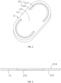
FIG. 2 is a schematic view of an explosion-proof sheet in an embodiment of the present application (a strengthening rib on the pressure release portion is omitted); -
FIG. 3 is a schematic cross-sectional view of a top cover at the explosion-proof hole in an embodiment of the present application; -
FIG. 4 is a top view of the explosion-proof sheet inFIG. 2 ; -
FIG. 5 is a schematic view of another explosion-proof sheet in an embodiment of the present application (a reinforcing rib on the pressure release portion is omitted); -
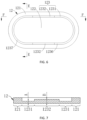
FIG. 6 is a top view of the explosion-proof sheet inFIG. 5 ; -
FIG. 7 is a sectional view at F-F inFIG. 6 ; -
FIG. 8 is a sectional view at E-E inFIG. 6 ; -
FIG. 9 is a schematic view of an annular groove of an explosion-proof sheet inFIG. 8 after improvement. - Reference numerals: 100- secondary battery, 1- top cover assembly, 11- top cover, 111- explosion-proof hole, 112- liquid injection hole, 113- bottom surface, 114- top surface, 115- sink, 12- explosion-proof sheet , 121- fixing portion, 122- pressure release portion, 123- connecting portion, 1231- weakened region, 1232- strengthened region, 1233- notch of annular groove, 1234- groove bottom of annular groove, 1235-side wall, 1236- straight groove, 1237- arc-shaped groove, 124- front surface, 125-back surface, 13- protective sheet, 2- casing.
- Hereinafter, the technical solutions in the embodiments of the present application will be described clearly and thoroughly in conjunction with the drawings in the embodiments of the present application. Obviously, the described embodiments are merely some of the embodiments of the present application, but not all of the embodiments. Based on the embodiments in the present application, all other embodiments obtained by a person of ordinary skill in the art without creative efforts should fall within the protection scope of the present application.
- In the present application, the direction or positional relationship indicated by terms "on/above", "under/below", "left", "right", "front", "back", "top", "bottom", "inside", "outside", "in the middle of", "vertical", "horizontal", "lateral", "longitudinal", etc. is the direction or positional relationship based on that shown in the drawings. These terms are primarily intended to better describe the present application and its embodiments and are not used to define that the indicated device, element or component must has a particular direction, or be constructed and operated in a particular direction.
- Moreover, some of the terms may be used to indicate other meanings in addition to the direction or positional relationship, for example, the term "on/above" may also be used to indicate a certain dependency or connection relationship in some cases. For those of ordinary skill in the art, the specific meanings of the terms in the present application may be understood according to specific situations.
- In addition, the terms "install", "arrange", "provide", "provided with", "connect" and "couple" should be understood broadly. For example, it can be a fixed connection, a detachable connection, an integral structure, a mechanical connection, an electrical connection, a direct connection, an indirect connection through an intermediate medium, or a communication between two devices, elements or components. For those of ordinary skill in the art, the specific meanings of the above terms in the present application can be understood according to specific situations.
- In addition, the terms "first", "second", etc., are used primarily to distinguish different devices, elements or components (the specific type and construction may be the same or different) and are not used to indicate or imply the relative importance or quantity of the indicated device, element or component. Terms like "multiple"/"a plurality of" refer to the number of two or more than two, except for clear and particular restriction.
- Before explaining the technical solutions of the present application, the application scenarios involved in the embodiments of the present application are explained. During the use of the battery, when the battery is used in an overcharged, overdischarged, short-circuited or harsh environment (when the battery is used in a high temperature, high humidity, high pressure or low pressure environment), a large amount of gas will be generated inside the battery and the temperature of the battery will also rise sharply, resulting in an increase in the internal pressure of the battery, which will cause a certain danger to the user. In the related art, in order to ensure safety of the battery, an explosion-proof hole is generally opened on a top cover of the battery, and an explosion-proof sheet is covered at the explosion-proof hole. When the pressure inside the battery reaches a threshold, the gas will rupture the explosion-proof sheet for pressure release to ensure the safety of the battery. However, when the pressure inside the battery rises sharply, the explosion-proof sheet is likely to be separated from the top cover as a whole, and there are safety problems for other components and users.
- Based on this, the present application provides an explosion-proof sheet, a top cover assembly and a battery to solve the above problems.
- The technical solutions of the present application will be further described below with reference to specific embodiments and accompanying drawings.
- Please refer to
FIG. 1. FIG. 1 is an exploded view of a battery in an embodiment of the present application. Among them, the present application provides asecondary battery 100. Thesecondary battery 100 includes a top cover assembly 1 and a casing 2, the top cover assembly 1 is covered on an opening of the casing 2, so that the top cover assembly 1 and the casing 2 may be enclosed to form a sealed space, and a cell structure (not shown in the figure) of thesecondary battery 100 may be accommodated in the space. - Specifically, referring to
FIG. 1 andFIG. 2 , the top cover assembly 1 includes atop cover 11 and an explosion-proof sheet 12. Thetop cover 11 is provided with an explosion-proof hole 111, and the fixingportion 121 of the explosion-proof sheet 12 has a sealed connection with an edge of an end face of the explosion-proof hole 111. Therefore, when thesecondary battery 100 is in normal use, the explosion-proof sheet 12 can seal the explosion-proof hole 111 to prevent interior of thesecondary battery 100 from being affected by the outside. At the same time, due to an improvement of the explosion-proof sheet 12 in the present application, when a pressure inside thesecondary battery 100 reaches a threshold, the explosion-proof sheet 12 will be partially separated from thetop cover 11 to perform pressure release, and it is different for the explosion-proof sheet 12 to be separated from the top cover assembly 1 as a whole. Therefore, the usage safety of thesecondary battery 100 is improved and safety of the user is effectively ensured. - In addition, the top cover assembly 1 may further include a
protective sheet 13, which is arranged on an outer side of thetop cover 11 and covers the explosion-proof hole 111 and the explosion-proof sheet 12. Therefore, it can prevent the user from accidentally touching the explosion-proof sheet 12 and causing the explosion-proof sheet 12 to deform, and prevent foreign objects from falling on the surface of the explosion-proof sheet and causing the explosion-proof sheet invalidation. In addition, when the explosion-proof sheet 12 is partially separated from thetop cover 11 for pressure release, theprotective sheet 13 can buffer deformation of the explosion-proof sheet 12, thereby improving safety of the pressure release. - It should be noted that, the sealed connection of the fixing
portion 121 of the explosion-proof sheet 12 and the edge of the explosion-proof hole 111 may be in various ways, such as snap connection, bonding or welding, etc. In the present application, the explosion-proof sheet 12 is fixed onto thetop cover 11 by welding, thereby sealing of the explosion-proof sheet 12 and thetop cover 11 is ensured, and problems such as liquid leakage and air leakage are avoided. Preferably, as shown inFIG. 3 , in the present application, one side of abottom surface 113 of thetop cover 11 is recessed toward atop surface 114 to form asink 115. The explosion-proof sheet 12 is embedded in thesink 115, and the fixingportion 121 of the explosion-proof sheet 12 is welded with the bottom of the sink. A depth of the sink is approximately the same as a thickness of the explosion-proof sheet. In this way, when the fixingportion 121 of the explosion-proof sheet 12 is attached to the surface of the sink, the explosion-proof sheet 12 and the bottom surface of the top cover are substantially on the same plane, thereby preventing the explosion-proof sheet 12 from protruding from the bottom surface of thetop cover 11 and reducing the internal space of the secondary battery occupied by of the explosion-proof sheet 12. So that an overall volume of the battery may be reduced, and the explosion-proof sheet 12 may also be prevented from interfering with other components and affecting normal creep of electrolyte, thereby reliability of electrochemical performance of the battery may be ensured. That is, the assembling accuracy of the explosion-proof sheet 12 and thetop cover 11 is crucial to the performance and safety of thesecondary battery 100. - Next, the improved explosion-
proof sheet 12 in the present application will be explained in detail below. Please refer toFIGS. 2 to 6 . Specifically, the explosion-proof sheet 12 includes apressure release portion 122 and a fixingportion 121 disposed around thepressure release portion 122. Thepressure release portion 122 and the fixingportion 121 are connected by a connectingportion 123, and the connectingportion 123 includes a weakenedregion 1231 and a strengthenedregion 1232. A wall thickness of the weakenedregion 1231 is smaller than a wall thickness of the strengthenedregion 1232. - Among them, when the explosion-
proof sheet 12 is connected to thetop cover 11, the fixingportion 121 of the explosion-proof sheet 12 may have a sealed connection with a hole wall surface of the explosion-proof hole 111, and the fixingportion 121 is arranged around thepressure release portion 122. That is, thepressure release portion 122 is located inside the fixingportion 121, so thepressure release portion 122 is arranged opposite to the explosion-proof hole 111. At this time, thepressure release portion 122 and the fixingportion 121 are connected by the connectingportion 123, the connectingportion 123 includes a weakenedregion 1231 and a strengthenedregion 1232, and the wall thickness of the weakenedregion 1231 is smaller than the wall thickness of the strengthenedregion 1232. Therefore, when a pressure inside thesecondary battery 100 reaches a threshold, the weakenedregion 1231 of the connectingportion 123 cracks first, and the strengthenedregion 1232 of the connecting portion remains connected. Thus a part where thepressure release portion 122 joins the weakenedregion 1231 is separated with the fixingportion 121 and a vent (not shown in the figures) is formed, so that gas inside the battery can be discharged from the vent, and the part where thepressure release portion 122 joins the strengthenedregion 1232 may still remain connected with the fixingportion 121. It can be seen that when the explosion-proof sheet 12 performs pressure release, the fixingportion 121 is still be connected to the edge of the explosion-proof hole 111, and a part where thepressure release portion 122 joins the weakenedregion 1231 is separated from the fixingportion 121 and the pressure is released. The part where thepressure release portion 122 joins the strengthenedregion 1232 may still remain connected, so as to prevent the explosion-proof sheet 12 from being separated from thetop cover 11 as a whole when the pressure is released, thereby the usage safety of thesecondary battery 100 is improved. - It should be noted that, in order to further improve the usage safety of the
secondary battery 100, in the embodiment of the present application, the explosion-proof sheet 12 can be arranged on a surface of thetop cover 11 close to the casing 2, that is, the explosion-proof sheet 12 is arranged on a lower surface of thetop cover 11 inFIG. 1 . When thesecondary battery 100 performs pressure release, the gas inside thesecondary battery 100 is flushed out through the explosion-proof hole 111, and the gas inside thesecondary battery 100 is flushed out in a direction from the lower surface of thetop cover 11 to an upper surface of thetop cover 11. At this time, since the explosion-proof sheet 12 is arranged on the lower surface of thetop cover 11, and the fixingportion 121 of the explosion-proof sheet 12 is connected to the edge of the explosion-proof hole 111, the fixingportion 121 of the explosion-proof sheet 12 may be stably connected with thetop cover 11 to prevent the fixingportion 121 of the explosion-proof sheet 12 from being separated from thetop cover 11. - The length of the strengthened
region 1232 needs to be selected in a suitable range. If the length of the strengthenedregion 1232 is too long, explosion of the explosion-proof sheet 12 may be delayed. If the length of the strengthenedregion 1232 is too short, the strength of the strengthenedregion 1232 may be insufficient, so that thepressure release portion 122 may be blown up integrally when the explosion-proof sheet 12 is exploded. Therefore, the length of the strengthenedregion 1232 can be set to account for 1/6 to 1/3 of a total length of the connectingportion 123. In this way, the explosion-proof sheet 12 can explode in time, and thepressure release portion 122 can be prevented from being blown up integrally, thereby the usage safety of the battery is further improved. - In the above embodiment, in order to ensure that when the gas pressure inside the
secondary battery 100 is greater than or equal to a critical value P, the explosion-proof sheet 12 can be cracked in the connectingportion 123. The thickness d1 of the connectingportion 123, the thickness d2 of thepressure release portion 122, and the thickness d3 of the fixingportion 121 satisfy the following relationships: 0.3≤d1/d2≤0.4, 0.5≤d2/d3≤0.6, and the critical value P of the gas pressure inside thesecondary battery 100 and the thickness d1 of the connectingportion 123 satisfy the following relationship: 2.7≤P/ d1≤7.3, where the unit of P is MPa, and the unit of d1 is millimeter. In this way, it can be ensured that the explosion-proof sheet can be opened in time, thereby invalidation of the explosion-proof sheet may be avoided. Specifically, d1:d2:d3=11:30:55, P: d1=5.5. For example, the thickness d1 of the connectingportion 123 may be 0.11 mm, the thickness d2 of thepressure release portion 122 may be 0.3 mm, and the thickness d3 of the fixingportion 121 may be 0.55 mm. Therefore, when the gas pressure P inside thesecondary battery 100 is greater than or equal to 0.6 MPa, the explosion-proof sheet 12 will start to perform pressure release. In this way, it can be more accurately ensured that the explosion-proof sheet 12 explodes successfully when the gas pressure inside the battery reaches the threshold. - In some embodiments, please refer to
FIG. 2 andFIG. 4 , the weakenedregion 1231 forms a non-closed groove, and the wall thickness of the strengthenedregion 1232 is equal to the wall thickness of the explosion-proof sheet 12. Among them, when the weakenedregion 1231 forms a closed groove, since the weakenedregion 1231 is cracked during pressure release, thepressure release portion 122 inside the weakenedregion 1231 will be separated from thetop cover 11, thereby causing danger to the user. In the present application, the weakenedregion 1231 forms a non-closed groove, so that after the weakenedregion 1231 is cracked, the part where thepressure release portion 122 joins the strengthenedregion 1232 will still be connected to the fixingportion 121, so that a danger to the user caused by thepressure release portion 122 being separated from thetop cover 11 is avoided. At the same time, the wall thickness of the strengthenedregion 1232 is equal to the wall thickness of the explosion-proof sheet 12, so that the strengthenedregion 1232 can have a greater structural strength. Accordingly, thepressure release portion 122 connected with the strengthenedregion 1232 and the fixingportion 121 are stably connected together. This effectively prevents thepressure release portion 122 from being separated from thetop cover 11, and the usage safety of thesecondary battery 100 is effectively increased. - In other embodiments, please refer to
FIGS. 5 and6 , the connectingportion 123 is an annular groove, and the thickness of the connecting portion at the groove bottom of the weakenedregion 1231 is smaller than the thickness of the connecting portion at the groove bottom of the strengthenedregion 1232. - Among them, when the pressure inside the
secondary battery 100 reaches the threshold, the weakenedregion 1231 is cracked to make thepressure release portion 122 being partially separate from the fixingportion 121 for pressure release. However, when the pressure inside thesecondary battery 100 is much greater than the threshold, that is, when the pressure release port formed by the cracking of the weakenedregion 1231 cannot satisfy the pressure release, thesecondary battery 100 may explode at this time, thereby causing a greater danger to the user. Based on this, the connectingportion 123 in the embodiment of the present application is an annular groove, and the thickness of the connecting portion at the groove bottom of the strengthenedregion 1232 is greater than the thickness of the connecting portion at the groove bottom of the weakenedregion 1231. Therefore, when the pressure inside thesecondary battery 100 reaches the threshold, the weakenedregion 1231 is cracked so that thepressure release portion 122 and the fixingportion 121 will be partially separated for pressure release, while the strengthenedregion 1232 will not be cracked so that thepressure release portion 122 may still be partially connected with the fixingportion 121 to prevent thepressure release portion 122 from being separated with thetop cover 11 and causing a danger to the user. But when the pressure inside thesecondary battery 100 is much greater than the threshold, the pressure release port formed by the cracking of the weakenedregion 1231 alone cannot satisfy the pressure release. In order to avoid the explosion of thebattery 100 causing more damage to the user, in the present embodiment, the connectingportion 123 is set as an annular groove, and the thickness of the connecting portion at the groove bottom of the strengthenedregion 1232 is greater than that of the weakenedregion 1231. As a result, the weakenedregion 1231 and the strengthenedregion 1232 are cracked in sequence, and then thepressure release portion 122 is separated from thetop cover 11, so as to quickly perform pressure release of thesecondary battery 100 and avoid greater danger. - In addition, the connecting
portion 123 is set as an annular groove, that is, the wall thickness of the strengthenedregion 1232 is smaller than the thickness of the explosion-proof sheet 12, so that an overall thickness of the explosion-proof sheet 12 can also be reduced, thereby facilitating the lightweight of thesecondary battery 100. Please refer toFIG. 6 and FIG. 7 , the thickness of the connecting portion at the groove bottom of the weakenedregion 1231 is A, and the thickness of the connecting portion at the groove bottom of the strengthenedregion 1232 is B, 0.65≤A/ B≤0.75. Among them, when the pressure inside thesecondary battery 100 reaches the threshold, thepressure release portion 122 is under pressure and deformed, and drives the weakenedregion 1231 being deformed to crack for pressure release, but the deformation of thepressure release portion 122 also brings deformation of the strengthenedregion 1232. The embodiment of the present application sets the ratio of the thickness of the connecting portion at the groove bottom of the weakenedregion 1231 to the thickness of the connecting portion at the groove bottom of the strengthenedregion 1232 to 0.65≤A/ B≤0.75, which can effectively avoid that when the pressure inside thesecondary battery 100 reaches the threshold, the strengthenedregion 1232 also cracks. - Further, A/ B can be 11:15. For example, the wall thickness A of the groove bottom of the weakened
region 1231 is 0.11 mm, and the wall thickness B of the groove bottom of the strengthenedregion 1232 is 0.15 mm. Among them, the wall thickness A of the groove bottom of the weakenedregion 1231 is 0.11 mm, which can ensure that thesecondary battery 100 has high structural strength during normal use and avoid cracking of the weakenedregion 1231 during normal use of thesecondary battery 100, and can also ensure that when the pressure inside thesecondary battery 100 reaches the threshold, the weakenedregion 1231 is cracked for pressure release. The wall thickness B of the groove bottom of the strengthenedregion 1232 is 0.15mm, which can ensure that when the pressure inside thesecondary battery 100 reaches the threshold thesecondary battery 100 has high structural strength during normal use and avoid cracking of the strengthenedregion 1232 which causes thepressure release portion 122 being separated from thetop cover 11 thereby causing danger to users when the pressure inside thesecondary battery 100 reaches the threshold. And it can also ensure that when the pressure inside thesecondary battery 100 is much greater than the threshold, the strengthenedregion 1232 may be cracked, and then thepressure release portion 122 can be separated from thetop cover 11, so that the pressure inside thesecondary battery 100 can be quickly released, and the explosion of thesecondary battery 100 which causes greater danger to the user can be avoided. Please refer toFIG. 6 andFIG. 8 , the width of thenotch 1233 of the annular groove can be equal to the width of thegroove bottom 1234 of the annular groove. In another embodiment, referring toFIG. 6 andFIG. 9 , the width of thenotch 1233 of the annular groove can also be greater than the width of thegroove bottom 1234 of the annular groove. That is, the cross-sectional shape of the annular groove is an inverted trapezoidal structure. The annular groove of the inverted trapezoidal structure is easy to be stamped and formed, and can avoid stress concentration between thegroove bottom 1234 and theside wall 1235 of the annular groove, and prevent cracking at the junction of theside wall 1235 and thegroove bottom 1234 in advance when the internal pressure of the battery does not reach the critical value, which affects the normal use of the battery. - Further, an angle α between the
side wall 1235 of the annular groove and thegroove bottom 1234 of the annular groove satisfies: 90°<α≤120°. When α is too small, stress concentration may be formed between theside wall 1235 and thegroove bottom 1234, and the junction of theside wall 1235 and thegroove bottom 1234 is cracked in advance when the internal pressure of the battery does not reach the threshold, and the normal use of the battery is affected. When α is too large, the depth of the annular groove may be small, so that when the internal pressure of the battery reaches a critical value, it cannot be exploded in time. Therefore, when the angle between theside wall 1235 of the annular groove and thegroove bottom 1234 of the annular groove is 90°<α≤120°, not only the stress concentration between theside wall 1235 and thegroove bottom 1234 can be avoided, but also the depth of the annular groove can be prevented from being small, so that the explosion-proof sheet 12 can perform the pressure release successfully. - Please refer back to
FIG. 5 andFIG. 6 , the annular groove has a stadium-shaped structure. The stadium-shaped structure includes astraight groove 1236 and an arc-shapedgroove 1237. The strengthenedregion 1232 is located at thestraight groove 1236, and the weakened region is located at the arc-shapedgroove 1237. - Specifically, there may be one or two
strengthened regions 1232, and when there is one strengthenedregion 1232, the strengthenedregion 1232 is located at one of thestraight grooves 1236. - When there are two strengthened
regions 1232, as shown inFIG. 6 , the two strengthenedregions 1232 are respectively located at the twostraight grooves 1236 . - Among them, a stadium-shape refers to a closed figure formed by bisecting a circle into two semi-circular arcs through the center of the circle and translating them in opposite directions, and connecting the endpoints of the two semi-circular arcs with two equal-length parallel lines. It can be seen that the annular groove of the stadium-shaped structure includes the
straight groove 1236 and the arc-shapedgroove 1237. In the embodiment of the present application, two strengthenedregions 1232 are respectively arranged on the twostraight grooves 1236, and two weakenedregions 1231 are respectively arranged on the two arc-shapedgrooves 1237. In this way, when the pressure inside thesecondary battery 100 reaches the threshold, the weakenedregions 1231 at the arc-shapedgrooves 1237 located at both sides of thestraight grooves 1236 will be cracked, and the strengthenedregions 1232 on thestraight grooves 1236 located between the two arc-shapedgrooves 1237 will not be cracked. Therefore, vents can be formed on both sides of thestraight groove 1236, and the gas in thesecondary battery 100 can be discharged from two different vents, so that pressure concentration can be avoided during pressure release of thesecondary battery 100, thereby increasing the efficiency of pressure release of thesecondary battery 100 and improving the usage safety of thesecondary battery 100. - In the above embodiment, as shown in
FIG. 1 , thetop cover 11 is usually provided with aliquid injection hole 112. When the relative positions of theliquid injection hole 112 and the explosion-proof sheet 12 are set, theliquid injection hole 112 can be arranged to be close to thestraight groove 1236 of the explosion-proof sheet 12. Therefore, when the pressure is released by the explosion-proof sheet 12, substance inside the battery may be ejected from the explosion-proof hole 111 along with the cracking of the explosion-proof sheet 12. Since the strengthenedregion 1232 is located at thestraight groove 1236, a part of thepressure release portion 122 located at thestraight groove 1236 is cracked, thereby preventing the substance inside the battery from entering theliquid injection hole 112 when the explosion-proof sheet 12 is cracked. - Please refer to
FIG. 1 ,FIG. 5 andFIG. 8 , the explosion-proof sheet 12 has afront surface 124 and aback surface 125 arranged opposite to each other. Thefront surface 124 is a surface of the explosion-proof sheet 12 facing away from the interior of thesecondary battery 100. The annular groove can be arranged on thefront surface 124, and can also be arranged on theback surface 125, as long as it can be cracked when the internal pressure of thesecondary battery 100 is greater than the threshold, and it is not specifically limited in the present application. - Preferably, in the embodiment of the present application, the annular groove is formed on the
front surface 124 of the explosion-proof sheet 12. Wherein, after the fixingportion 121 of the explosion-proof sheet 12 is connected to the edge of the explosion-proof hole 111 on thetop cover 11, when the internal pressure of thesecondary battery 100 is greater than the threshold, thepressure release portion 122 is deformed in a direction away from the interior of thesecondary battery 100 and drive the weakenedregion 1231 of the annular groove to be cracked. At this time, if the annular groove is formed on theback surface 125 of the explosion-proof sheet 12, thepressure release portion 122 deforms and drives the weakenedregion 1231 of the annular groove to be cracked. Thesidewalls 1235 on both sides of the groove first approach each other and then separate, which causes thesidewalls 1235 on both sides of the annular groove to press against each other, and is not conducive to the cracking of the weakenedregion 1231 of the annular groove. In the embodiment of the present application, the annular groove is formed on thefront surface 124 of the explosion-proof sheet 12, then when thepressure release portion 122 is deformed and drives the weakenedregion 1231 of the annular groove to be cracked, theside walls 1235 of the weakenedregion 1231 of the annular groove will be away from each other until they are separated, so as to facilitate the cracking of the weakenedregion 1231 of the annular groove for pressure release. - To sum up, in the present application, the explosion-
proof sheet 12 includes thepressure release portion 122 and the fixingportion 121 arranged around thepressure release portion 122. Thepressure release portion 122 and the fixingportion 121 are connected by the connectingportion 123, and the connectingportion 123 includes a weakenedregion 1231 and a strengthenedregion 1232. The wall thickness of the weakenedregion 1231 is smaller than the wall thickness of the strengthenedregion 1232. After the fixingportion 121 is connected to the edge of the explosion-proof hole 111 on thetop cover 11, when thesecondary battery 100 performs pressure release, the fixingportion 121 is still be connected to the edge of the explosion-proof hole 111, and the part where thepressure release portion 122 joins the weakenedregion 1231 is separated from the fixingportion 121 and the pressure is released. The part where thepressure release portion 122 joins the strengthenedregion 1232 may still remain connected, so as to prevent the explosion-proof sheet 12 from being separated from thetop cover 11 as a whole when the pressure is released, thereby the usage safety of thesecondary battery 100 is improved. - The explosion-proof sheet, the top cover assembly and the battery disclosed in the embodiments of the present application are described above in detail. The principle and implementations herein are described through specific examples. The description about the embodiments is merely provided to help understand the method and core ideas of the present application. In addition, persons of ordinary skill in the art can make modifications to the present application in terms of the specific implementations and application scopes based on the ideas of the present application. To sum up, the content of specification shall not be construed as a limit to the present application.
Claims (12)
- An explosion-proof sheet (12) for a secondary battery (100), wherein the secondary battery (100) comprises a top cover (11) provided with an explosion-proof hole (111), the explosion-proof sheet (12) is fitted on the top cover (11) to close the explosion-proof hole (111), characterized in that the explosion-proof sheet (12) comprises:a pressure release portion (122), arranged opposite to the explosion-proof hole (111);a fixing portion (121), surrounding the pressure release portion (122) and connected to the top cover (11);a connecting portion (123), located between the pressure release portion (122) and the fixing portion (121), and connecting the pressure release portion (122) and the fixing portion (121);wherein, a thickness of a part of the connecting portion (123) is greater than a thickness of a remaining part of the connecting portion (123).
- The explosion-proof sheet (12) for a secondary battery (100) according to claim 1, characterized in that the connecting portion (123) comprises at least one strengthened region (1232) and at least one weakened region (1231), a thickness of the strengthened region (1232) is greater than a thickness of the weakened region (1231), and a length of the strengthened region (1232) accounts for 1/6 to 1/3 of a total length of the connecting portion (123).
- The explosion-proof sheet (12) for a secondary battery (100) according to claim 1 or 2, characterized in that the connecting portion (123) has a thickness d1, the pressure release portion (122) has a thickness d2, and the fixing portion (121) has a thickness d3, wherein a ratio of d1 to d2 (d1/d2) is: 0.3 ≤ d1/d2 ≤ 0.4, and a ratio of d2 to d3 (d2/d3) is 0.5 ≤ d2/d3 ≤ 0.6, and when an air pressure inside the secondary battery (100) is greater than or equal to a threshold, the explosion-proof sheet (12) is cracked in the connecting portion (123), wherein a ratio of an air pressure P inside the secondary battery (100) and the thickness d1 of the connecting portion (123) is P/d1 and satisfies the following relationship: 2.7 ≤ P/d1 ≤ 7.3, wherein the unit of P is MPa, and the unit of d1 is millimeter.
- The explosion-proof sheet (12) for a secondary battery (100) according to claim 3, characterized in that a ratio of d1 to d2 to d3 is d1: d2: d3 = 11 : 30 : 55, the P/ d1 = 5.5.
- The explosion-proof sheet (12) for a secondary battery (100) according to any of claims 2 to 4, characterized in that the connecting portion (123) comprises an annular groove, and a thickness of the connecting portion (123) at a groove bottom of the weakened region (1231) is smaller than a thickness of the connecting portion (123) at a groove bottom of the strengthened region (1232).
- The explosion-proof sheet (12) for a secondary battery (100) according to claim 5, characterized in that the thickness of the connecting portion (123) at the groove bottom of the weakened region (1231) is A, and the thickness of the connecting portion (123) at the groove bottom of the strengthened region (1232) is B, and a ratio of A to B (A/B) satisfy the following relationship: 0.65 ≤ A/B ≤ 0.75.
- The explosion-proof sheet (12) for a secondary battery (100) according to claim 6, characterized in that A/B = 11 : 15.
- The explosion-proof sheet (12) for a secondary battery (100) according to any of claims 5 to 7, characterized in that a cross-sectional shape of the annular groove is an inverted trapezoidal structure, and an angle α between a side wall (1235) and the groove bottom (1234) of the annular groove satisfies: 90° < α ≤ 120°.
- The explosion-proof sheet (12) for a secondary battery (100) according to any of claims 5 to 8, characterized in that the annular groove has a stadium-shaped structure, and the stadium-shaped structure comprises two straight grooves (1236) and two arc-shaped grooves (1237), the two straight grooves (1236) are parallel to each other, and the two arc-shaped grooves (1237) are respectively connected to two ends of the two straight grooves, wherein the connecting portion (123) comprises two strengthened regions (1232), and the two strengthened regions (1232) are respectively located at the two straight grooves (1236).
- The explosion-proof sheet (12) for a secondary battery (100) according to claim 9, characterized in that a liquid injection hole (112) is further provided on the top cover (11), and the liquid injection hole (112) is arranged close to the straight groove (1236).
- A top cover assembly (1), characterized by comprising:a top cover (11), provided with an explosion-proof hole (111); andan explosion-proof sheet (12) for a secondary battery (100) according to any of claims 1 to 10, wherein a fixing portion (121) of the explosion-proof sheet (12) for a secondary battery (100) has a sealed connection with an edge of the explosion-proof hole (111).
- A secondary battery (100), characterized by comprising a top cover assembly (1) according to claim 11.
Applications Claiming Priority (1)
| Application Number | Priority Date | Filing Date | Title |
|---|---|---|---|
| CN202122458310.6U CN216120624U (en) | 2021-10-12 | 2021-10-12 | Secondary cell's explosion-proof piece, top cap subassembly and secondary cell |
Publications (2)
| Publication Number | Publication Date |
|---|---|
| EP4167334A1 true EP4167334A1 (en) | 2023-04-19 |
| EP4167334B1 EP4167334B1 (en) | 2024-04-24 |
Family
ID=80692124
Family Applications (1)
| Application Number | Title | Priority Date | Filing Date |
|---|---|---|---|
| EP22197276.3A Active EP4167334B1 (en) | 2021-10-12 | 2022-09-23 | Explosion-proof sheet, top cover assembly of secondary battery, and secondary battery |
Country Status (8)
| Country | Link |
|---|---|
| US (1) | US12555850B2 (en) |
| EP (1) | EP4167334B1 (en) |
| CN (1) | CN216120624U (en) |
| ES (1) | ES2983257T3 (en) |
| FI (1) | FI4167334T3 (en) |
| HU (1) | HUE067369T2 (en) |
| LT (1) | LT4167334T (en) |
| PT (1) | PT4167334T (en) |
Cited By (3)
| Publication number | Priority date | Publication date | Assignee | Title |
|---|---|---|---|---|
| CN116557596A (en) * | 2023-07-12 | 2023-08-08 | 深圳海辰储能控制技术有限公司 | Explosion-proof valve, end cover assembly, battery and energy storage device |
| WO2026011281A1 (en) * | 2024-07-08 | 2026-01-15 | Powerco Se | Housing, battery cell, battery and power-using device |
| US12555850B2 (en) | 2021-10-12 | 2026-02-17 | Hithium Tech Hk Limited | Explosion-proof sheet, top cover assembly of secondary battery, and secondary battery |
Families Citing this family (21)
| Publication number | Priority date | Publication date | Assignee | Title |
|---|---|---|---|---|
| US12107285B2 (en) * | 2022-01-13 | 2024-10-01 | GM Global Technology Operations LLC | Systems and methods for responding to thermal excursions in a battery |
| EP4307445A4 (en) * | 2022-05-16 | 2024-04-24 | Contemporary Amperex Technology Co., Limited | End cap, battery cell, battery and power consuming device |
| CN117413425A (en) * | 2022-05-16 | 2024-01-16 | 宁德时代新能源科技股份有限公司 | End cover, battery monomer, battery and electric equipment |
| KR20240070939A (en) * | 2022-11-15 | 2024-05-22 | 주식회사 엘지에너지솔루션 | Bidirectional venting device and secondary battery having the same |
| WO2024148518A1 (en) * | 2023-01-10 | 2024-07-18 | 宁德时代新能源科技股份有限公司 | Battery cell, battery, and electrical device |
| JP1773960S (en) * | 2023-03-03 | 2024-06-25 | Battery, Electric | |
| CN116259895B (en) * | 2023-04-28 | 2025-07-04 | 厦门海辰储能科技股份有限公司 | End cover assembly, energy storage device and household energy storage system |
| CN116759760B (en) * | 2023-08-16 | 2023-10-13 | 深圳海辰储能控制技术有限公司 | End cover components, energy storage devices and energy storage systems |
| CN220753671U (en) * | 2023-08-31 | 2024-04-09 | 合肥国轩高科动力能源有限公司 | Explosion-proof valve of battery, battery cover plate assembly and battery |
| CN121039885A (en) * | 2023-11-21 | 2025-11-28 | 宁德时代新能源科技股份有限公司 | Battery cells, batteries and electrical devices |
| JP1776702S (en) * | 2023-12-05 | 2024-07-30 | Battery case | |
| JP1776653S (en) * | 2023-12-05 | 2024-07-30 | Battery case | |
| JP1776701S (en) * | 2023-12-05 | 2024-07-30 | Battery case | |
| WO2025138199A1 (en) * | 2023-12-29 | 2025-07-03 | 惠州亿纬动力电池有限公司 | Explosion-proof structure, and battery |
| WO2025138203A1 (en) * | 2023-12-29 | 2025-07-03 | 惠州亿纬动力电池有限公司 | Cover plate, battery, and battery pack |
| WO2025138201A1 (en) * | 2023-12-29 | 2025-07-03 | 惠州亿纬动力电池有限公司 | Anti-explosion structure, battery, and battery pack |
| WO2025138197A1 (en) * | 2023-12-29 | 2025-07-03 | 惠州亿纬动力电池有限公司 | Battery anti-explosion structure, battery, and battery pack |
| CN120613538A (en) * | 2024-03-07 | 2025-09-09 | 宁德时代新能源科技股份有限公司 | Battery cells, batteries, and electrical devices |
| CN222394998U (en) * | 2024-05-07 | 2025-01-24 | 浙江吉利控股集团有限公司 | Explosion-proof valve and battery |
| WO2026060666A1 (en) * | 2024-09-20 | 2026-03-26 | 宁德时代新能源科技股份有限公司 | Battery cell, pressure relief mechanism, battery, and electric device |
| CN121076390B (en) * | 2025-11-03 | 2026-03-20 | 蜂巢能源科技股份有限公司 | Battery cells, battery packs, and electrical equipment |
Citations (3)
| Publication number | Priority date | Publication date | Assignee | Title |
|---|---|---|---|---|
| CN212323152U (en) * | 2020-05-25 | 2021-01-08 | 欣旺达电动汽车电池有限公司 | An explosion-proof valve and a single battery |
| CN112382826A (en) * | 2021-01-15 | 2021-02-19 | 蜂巢能源科技有限公司 | A explosion-proof valve, electric core and battery module for electric core |
| WO2021187089A1 (en) * | 2020-03-18 | 2021-09-23 | 冨士発條株式会社 | Battery lid |
Family Cites Families (4)
| Publication number | Priority date | Publication date | Assignee | Title |
|---|---|---|---|---|
| US6132900A (en) * | 1996-12-25 | 2000-10-17 | Matsushita Electric Industrial Co., Ltd. | Method of production of non-aqueous electrolyte battery and seal plate thereof |
| CN2701082Y (en) * | 2004-06-01 | 2005-05-18 | 肇庆市风华锂电池有限公司 | Battery security sealing stopper and sealing cover plate and battery thereof |
| CN101567432B (en) * | 2009-06-05 | 2011-06-15 | 深圳市科达利实业股份有限公司 | Lithium battery electric core explosion prevention and power-off protection device and producing method |
| CN216120624U (en) | 2021-10-12 | 2022-03-22 | 厦门海辰新能源科技有限公司 | Secondary cell's explosion-proof piece, top cap subassembly and secondary cell |
-
2021
- 2021-10-12 CN CN202122458310.6U patent/CN216120624U/en active Active
-
2022
- 2022-09-22 US US17/950,500 patent/US12555850B2/en active Active
- 2022-09-23 HU HUE22197276A patent/HUE067369T2/en unknown
- 2022-09-23 LT LTEP22197276.3T patent/LT4167334T/en unknown
- 2022-09-23 PT PT221972763T patent/PT4167334T/en unknown
- 2022-09-23 ES ES22197276T patent/ES2983257T3/en active Active
- 2022-09-23 FI FIEP22197276.3T patent/FI4167334T3/en active
- 2022-09-23 EP EP22197276.3A patent/EP4167334B1/en active Active
Patent Citations (3)
| Publication number | Priority date | Publication date | Assignee | Title |
|---|---|---|---|---|
| WO2021187089A1 (en) * | 2020-03-18 | 2021-09-23 | 冨士発條株式会社 | Battery lid |
| CN212323152U (en) * | 2020-05-25 | 2021-01-08 | 欣旺达电动汽车电池有限公司 | An explosion-proof valve and a single battery |
| CN112382826A (en) * | 2021-01-15 | 2021-02-19 | 蜂巢能源科技有限公司 | A explosion-proof valve, electric core and battery module for electric core |
Cited By (4)
| Publication number | Priority date | Publication date | Assignee | Title |
|---|---|---|---|---|
| US12555850B2 (en) | 2021-10-12 | 2026-02-17 | Hithium Tech Hk Limited | Explosion-proof sheet, top cover assembly of secondary battery, and secondary battery |
| CN116557596A (en) * | 2023-07-12 | 2023-08-08 | 深圳海辰储能控制技术有限公司 | Explosion-proof valve, end cover assembly, battery and energy storage device |
| CN116557596B (en) * | 2023-07-12 | 2023-08-29 | 深圳海辰储能控制技术有限公司 | Explosion-proof valves, end cap assemblies, batteries and energy storage devices |
| WO2026011281A1 (en) * | 2024-07-08 | 2026-01-15 | Powerco Se | Housing, battery cell, battery and power-using device |
Also Published As
| Publication number | Publication date |
|---|---|
| PT4167334T (en) | 2024-07-08 |
| CN216120624U (en) | 2022-03-22 |
| LT4167334T (en) | 2024-08-12 |
| FI4167334T3 (en) | 2024-06-24 |
| HUE067369T2 (en) | 2024-10-28 |
| US20230113132A1 (en) | 2023-04-13 |
| US12555850B2 (en) | 2026-02-17 |
| EP4167334B1 (en) | 2024-04-24 |
| ES2983257T3 (en) | 2024-10-22 |
Similar Documents
| Publication | Publication Date | Title |
|---|---|---|
| EP4167334A1 (en) | Explosion-proof sheet, top cover assembly of secondary battery, and secondary battery | |
| US20240162589A1 (en) | Lower plastic member, top cover assembly, energy storage device and electrical equipment | |
| US11949119B2 (en) | Cover assembly of secondary battery and secondary battery | |
| US20190245175A1 (en) | Battery module | |
| CN208014793U (en) | Connecting elements and rechargeable battery | |
| CN218919098U (en) | Lower plastic part, top cover assembly, energy storage device and electric equipment | |
| CN110429214A (en) | Lid assembly for secondary battery and secondary battery | |
| US11984624B1 (en) | Lower plastic assembly, energy storage apparatus, and electric device | |
| KR101440891B1 (en) | Rechargeable Battery | |
| CN116557596B (en) | Explosion-proof valves, end cap assemblies, batteries and energy storage devices | |
| US20240347822A1 (en) | End cover assembly, battery cell, battery, and electrical apparatus | |
| CN221239758U (en) | Cylindrical battery, battery pack and electronic equipment | |
| CN218887348U (en) | End cover, battery monomer, battery and consumer | |
| US20080070097A1 (en) | Secondary battery | |
| US20250046924A1 (en) | Battery and electronic device | |
| CN220914389U (en) | Battery cell cover plate, battery cell and battery pack | |
| EP4586384A1 (en) | Lower plastic part, top cover assembly, energy storage apparatus, and electric device | |
| CN220272692U (en) | End caps, batteries and energy storage devices | |
| US20240088513A1 (en) | Battery Pack | |
| CN217934139U (en) | Battery with improved battery capacity | |
| KR100646522B1 (en) | Lithium secondary battery | |
| CN221747432U (en) | Lower plastic and cover assembly | |
| CN218101471U (en) | End cover components, single cells, battery packs and electrical equipment | |
| JP2024535302A (en) | Electrochemical equipment and electrical appliances | |
| CN221885316U (en) | Battery top cap, battery and consumer |
Legal Events
| Date | Code | Title | Description |
|---|---|---|---|
| PUAI | Public reference made under article 153(3) epc to a published international application that has entered the european phase |
Free format text: ORIGINAL CODE: 0009012 |
|
| STAA | Information on the status of an ep patent application or granted ep patent |
Free format text: STATUS: THE APPLICATION HAS BEEN PUBLISHED |
|
| AK | Designated contracting states |
Kind code of ref document: A1 Designated state(s): AL AT BE BG CH CY CZ DE DK EE ES FI FR GB GR HR HU IE IS IT LI LT LU LV MC MK MT NL NO PL PT RO RS SE SI SK SM TR |
|
| STAA | Information on the status of an ep patent application or granted ep patent |
Free format text: STATUS: REQUEST FOR EXAMINATION WAS MADE |
|
| 17P | Request for examination filed |
Effective date: 20230512 |
|
| RBV | Designated contracting states (corrected) |
Designated state(s): AL AT BE BG CH CY CZ DE DK EE ES FI FR GB GR HR HU IE IS IT LI LT LU LV MC MK MT NL NO PL PT RO RS SE SI SK SM TR |
|
| STAA | Information on the status of an ep patent application or granted ep patent |
Free format text: STATUS: EXAMINATION IS IN PROGRESS |
|
| 17Q | First examination report despatched |
Effective date: 20230711 |
|
| GRAP | Despatch of communication of intention to grant a patent |
Free format text: ORIGINAL CODE: EPIDOSNIGR1 |
|
| STAA | Information on the status of an ep patent application or granted ep patent |
Free format text: STATUS: GRANT OF PATENT IS INTENDED |
|
| INTG | Intention to grant announced |
Effective date: 20240112 |
|
| GRAS | Grant fee paid |
Free format text: ORIGINAL CODE: EPIDOSNIGR3 |
|
| GRAA | (expected) grant |
Free format text: ORIGINAL CODE: 0009210 |
|
| STAA | Information on the status of an ep patent application or granted ep patent |
Free format text: STATUS: THE PATENT HAS BEEN GRANTED |
|
| RAP3 | Party data changed (applicant data changed or rights of an application transferred) |
Owner name: XIAMEN HITHIUM ENERGY STORAGE TECHNOLOGY CO., LTD. Owner name: SHENZHEN HITHIUM ENERGY STORAGE TECHNOLOGY CO., LTD. |
|
| AK | Designated contracting states |
Kind code of ref document: B1 Designated state(s): AL AT BE BG CH CY CZ DE DK EE ES FI FR GB GR HR HU IE IS IT LI LT LU LV MC MK MT NL NO PL PT RO RS SE SI SK SM TR |
|
| REG | Reference to a national code |
Ref country code: GB Ref legal event code: FG4D |
|
| REG | Reference to a national code |
Ref country code: CH Ref legal event code: EP |
|
| REG | Reference to a national code |
Ref country code: DE Ref legal event code: R096 Ref document number: 602022003049 Country of ref document: DE |
|
| REG | Reference to a national code |
Ref country code: IE Ref legal event code: FG4D |
|
| REG | Reference to a national code |
Ref country code: FI Ref legal event code: FGE |
|
| REG | Reference to a national code |
Ref country code: PT Ref legal event code: SC4A Ref document number: 4167334 Country of ref document: PT Date of ref document: 20240708 Kind code of ref document: T Free format text: AVAILABILITY OF NATIONAL TRANSLATION Effective date: 20240702 |
|
| REG | Reference to a national code |
Ref country code: NL Ref legal event code: FP |
|
| REG | Reference to a national code |
Ref country code: AT Ref legal event code: MK05 Ref document number: 1680613 Country of ref document: AT Kind code of ref document: T Effective date: 20240424 |
|
| PG25 | Lapsed in a contracting state [announced via postgrant information from national office to epo] |
Ref country code: IS Free format text: LAPSE BECAUSE OF FAILURE TO SUBMIT A TRANSLATION OF THE DESCRIPTION OR TO PAY THE FEE WITHIN THE PRESCRIBED TIME-LIMIT Effective date: 20240824 |
|
| PG25 | Lapsed in a contracting state [announced via postgrant information from national office to epo] |
Ref country code: BG Free format text: LAPSE BECAUSE OF FAILURE TO SUBMIT A TRANSLATION OF THE DESCRIPTION OR TO PAY THE FEE WITHIN THE PRESCRIBED TIME-LIMIT Effective date: 20240424 |
|
| PG25 | Lapsed in a contracting state [announced via postgrant information from national office to epo] |
Ref country code: HR Free format text: LAPSE BECAUSE OF FAILURE TO SUBMIT A TRANSLATION OF THE DESCRIPTION OR TO PAY THE FEE WITHIN THE PRESCRIBED TIME-LIMIT Effective date: 20240424 |
|
| PG25 | Lapsed in a contracting state [announced via postgrant information from national office to epo] |
Ref country code: GR Free format text: LAPSE BECAUSE OF FAILURE TO SUBMIT A TRANSLATION OF THE DESCRIPTION OR TO PAY THE FEE WITHIN THE PRESCRIBED TIME-LIMIT Effective date: 20240725 |
|
| REG | Reference to a national code |
Ref country code: ES Ref legal event code: FG2A Ref document number: 2983257 Country of ref document: ES Kind code of ref document: T3 Effective date: 20241022 |
|
| PG25 | Lapsed in a contracting state [announced via postgrant information from national office to epo] |
Ref country code: AT Free format text: LAPSE BECAUSE OF FAILURE TO SUBMIT A TRANSLATION OF THE DESCRIPTION OR TO PAY THE FEE WITHIN THE PRESCRIBED TIME-LIMIT Effective date: 20240424 |
|
| PG25 | Lapsed in a contracting state [announced via postgrant information from national office to epo] |
Ref country code: PL Free format text: LAPSE BECAUSE OF FAILURE TO SUBMIT A TRANSLATION OF THE DESCRIPTION OR TO PAY THE FEE WITHIN THE PRESCRIBED TIME-LIMIT Effective date: 20240424 |
|
| REG | Reference to a national code |
Ref country code: HU Ref legal event code: AG4A Ref document number: E067369 Country of ref document: HU |
|
| PG25 | Lapsed in a contracting state [announced via postgrant information from national office to epo] |
Ref country code: LV Free format text: LAPSE BECAUSE OF FAILURE TO SUBMIT A TRANSLATION OF THE DESCRIPTION OR TO PAY THE FEE WITHIN THE PRESCRIBED TIME-LIMIT Effective date: 20240424 |
|
| PG25 | Lapsed in a contracting state [announced via postgrant information from national office to epo] |
Ref country code: PL Free format text: LAPSE BECAUSE OF FAILURE TO SUBMIT A TRANSLATION OF THE DESCRIPTION OR TO PAY THE FEE WITHIN THE PRESCRIBED TIME-LIMIT Effective date: 20240424 Ref country code: NO Free format text: LAPSE BECAUSE OF FAILURE TO SUBMIT A TRANSLATION OF THE DESCRIPTION OR TO PAY THE FEE WITHIN THE PRESCRIBED TIME-LIMIT Effective date: 20240724 Ref country code: LV Free format text: LAPSE BECAUSE OF FAILURE TO SUBMIT A TRANSLATION OF THE DESCRIPTION OR TO PAY THE FEE WITHIN THE PRESCRIBED TIME-LIMIT Effective date: 20240424 Ref country code: IS Free format text: LAPSE BECAUSE OF FAILURE TO SUBMIT A TRANSLATION OF THE DESCRIPTION OR TO PAY THE FEE WITHIN THE PRESCRIBED TIME-LIMIT Effective date: 20240824 Ref country code: HR Free format text: LAPSE BECAUSE OF FAILURE TO SUBMIT A TRANSLATION OF THE DESCRIPTION OR TO PAY THE FEE WITHIN THE PRESCRIBED TIME-LIMIT Effective date: 20240424 Ref country code: GR Free format text: LAPSE BECAUSE OF FAILURE TO SUBMIT A TRANSLATION OF THE DESCRIPTION OR TO PAY THE FEE WITHIN THE PRESCRIBED TIME-LIMIT Effective date: 20240725 Ref country code: BG Free format text: LAPSE BECAUSE OF FAILURE TO SUBMIT A TRANSLATION OF THE DESCRIPTION OR TO PAY THE FEE WITHIN THE PRESCRIBED TIME-LIMIT Effective date: 20240424 Ref country code: AT Free format text: LAPSE BECAUSE OF FAILURE TO SUBMIT A TRANSLATION OF THE DESCRIPTION OR TO PAY THE FEE WITHIN THE PRESCRIBED TIME-LIMIT Effective date: 20240424 Ref country code: RS Free format text: LAPSE BECAUSE OF FAILURE TO SUBMIT A TRANSLATION OF THE DESCRIPTION OR TO PAY THE FEE WITHIN THE PRESCRIBED TIME-LIMIT Effective date: 20240724 |
|
| PG25 | Lapsed in a contracting state [announced via postgrant information from national office to epo] |
Ref country code: DK Free format text: LAPSE BECAUSE OF FAILURE TO SUBMIT A TRANSLATION OF THE DESCRIPTION OR TO PAY THE FEE WITHIN THE PRESCRIBED TIME-LIMIT Effective date: 20240424 |
|
| PG25 | Lapsed in a contracting state [announced via postgrant information from national office to epo] |
Ref country code: EE Free format text: LAPSE BECAUSE OF FAILURE TO SUBMIT A TRANSLATION OF THE DESCRIPTION OR TO PAY THE FEE WITHIN THE PRESCRIBED TIME-LIMIT Effective date: 20240424 |
|
| PG25 | Lapsed in a contracting state [announced via postgrant information from national office to epo] |
Ref country code: CZ Free format text: LAPSE BECAUSE OF FAILURE TO SUBMIT A TRANSLATION OF THE DESCRIPTION OR TO PAY THE FEE WITHIN THE PRESCRIBED TIME-LIMIT Effective date: 20240424 |
|
| PG25 | Lapsed in a contracting state [announced via postgrant information from national office to epo] |
Ref country code: SK Free format text: LAPSE BECAUSE OF FAILURE TO SUBMIT A TRANSLATION OF THE DESCRIPTION OR TO PAY THE FEE WITHIN THE PRESCRIBED TIME-LIMIT Effective date: 20240424 Ref country code: RO Free format text: LAPSE BECAUSE OF FAILURE TO SUBMIT A TRANSLATION OF THE DESCRIPTION OR TO PAY THE FEE WITHIN THE PRESCRIBED TIME-LIMIT Effective date: 20240424 |
|
| REG | Reference to a national code |
Ref country code: DE Ref legal event code: R097 Ref document number: 602022003049 Country of ref document: DE |
|
| PG25 | Lapsed in a contracting state [announced via postgrant information from national office to epo] |
Ref country code: SM Free format text: LAPSE BECAUSE OF FAILURE TO SUBMIT A TRANSLATION OF THE DESCRIPTION OR TO PAY THE FEE WITHIN THE PRESCRIBED TIME-LIMIT Effective date: 20240424 |
|
| PG25 | Lapsed in a contracting state [announced via postgrant information from national office to epo] |
Ref country code: SM Free format text: LAPSE BECAUSE OF FAILURE TO SUBMIT A TRANSLATION OF THE DESCRIPTION OR TO PAY THE FEE WITHIN THE PRESCRIBED TIME-LIMIT Effective date: 20240424 Ref country code: SK Free format text: LAPSE BECAUSE OF FAILURE TO SUBMIT A TRANSLATION OF THE DESCRIPTION OR TO PAY THE FEE WITHIN THE PRESCRIBED TIME-LIMIT Effective date: 20240424 Ref country code: RO Free format text: LAPSE BECAUSE OF FAILURE TO SUBMIT A TRANSLATION OF THE DESCRIPTION OR TO PAY THE FEE WITHIN THE PRESCRIBED TIME-LIMIT Effective date: 20240424 Ref country code: EE Free format text: LAPSE BECAUSE OF FAILURE TO SUBMIT A TRANSLATION OF THE DESCRIPTION OR TO PAY THE FEE WITHIN THE PRESCRIBED TIME-LIMIT Effective date: 20240424 Ref country code: DK Free format text: LAPSE BECAUSE OF FAILURE TO SUBMIT A TRANSLATION OF THE DESCRIPTION OR TO PAY THE FEE WITHIN THE PRESCRIBED TIME-LIMIT Effective date: 20240424 Ref country code: CZ Free format text: LAPSE BECAUSE OF FAILURE TO SUBMIT A TRANSLATION OF THE DESCRIPTION OR TO PAY THE FEE WITHIN THE PRESCRIBED TIME-LIMIT Effective date: 20240424 |
|
| P01 | Opt-out of the competence of the unified patent court (upc) registered |
Free format text: CASE NUMBER: APP_152/2025 Effective date: 20250103 |
|
| PLBE | No opposition filed within time limit |
Free format text: ORIGINAL CODE: 0009261 |
|
| STAA | Information on the status of an ep patent application or granted ep patent |
Free format text: STATUS: NO OPPOSITION FILED WITHIN TIME LIMIT |
|
| REG | Reference to a national code |
Ref country code: DE Ref legal event code: R081 Ref document number: 602022003049 Country of ref document: DE Owner name: HITHIUM TECH HK LIMITED, CN Free format text: FORMER OWNERS: SHENZHEN HITHIUM ENERGY STORAGE TECHNOLOGY CO., LTD., SHENZHEN, GUANGDONG, CN; XIAMEN HITHIUM ENERGY STORAGE TECHNOLOGY CO., LTD., XIAMEN, FUJIAN, CN |
|
| 26N | No opposition filed |
Effective date: 20250127 |
|
| REG | Reference to a national code |
Ref country code: GB Ref legal event code: 732E Free format text: REGISTERED BETWEEN 20250327 AND 20250402 |
|
| PG25 | Lapsed in a contracting state [announced via postgrant information from national office to epo] |
Ref country code: SI Free format text: LAPSE BECAUSE OF FAILURE TO SUBMIT A TRANSLATION OF THE DESCRIPTION OR TO PAY THE FEE WITHIN THE PRESCRIBED TIME-LIMIT Effective date: 20240424 Ref country code: MC Free format text: LAPSE BECAUSE OF FAILURE TO SUBMIT A TRANSLATION OF THE DESCRIPTION OR TO PAY THE FEE WITHIN THE PRESCRIBED TIME-LIMIT Effective date: 20240424 |
|
| REG | Reference to a national code |
Ref country code: HU Ref legal event code: GB9C Owner name: HITHIUM TECH HK LIMITED, HK Free format text: FORMER OWNER(S): SHENZHEN HITHIUM ENERGY STORAGE TECHNOLOGY CO., LTD., CN; XIAMEN HITHIUM ENERGY STORAGE TECHNOLOGY CO., LTD., CN Ref country code: HU Ref legal event code: FH1C Free format text: FORMER REPRESENTATIVE(S): SBGK SZABADALMI UEGYVIVOEI IRODA, HU Representative=s name: SBGK SZABADALMI UEGYVIVOEI IRODA, HU |
|
| REG | Reference to a national code |
Ref country code: BE Ref legal event code: MM Effective date: 20240930 |
|
| PG25 | Lapsed in a contracting state [announced via postgrant information from national office to epo] |
Ref country code: BE Free format text: LAPSE BECAUSE OF NON-PAYMENT OF DUE FEES Effective date: 20240930 |
|
| REG | Reference to a national code |
Ref country code: FI Ref legal event code: PCE Owner name: HITHIUM TECH HK LIMITED, CN |
|
| PG25 | Lapsed in a contracting state [announced via postgrant information from national office to epo] |
Ref country code: SE Free format text: LAPSE BECAUSE OF FAILURE TO SUBMIT A TRANSLATION OF THE DESCRIPTION OR TO PAY THE FEE WITHIN THE PRESCRIBED TIME-LIMIT Effective date: 20240424 |
|
| PGFP | Annual fee paid to national office [announced via postgrant information from national office to epo] |
Ref country code: LU Payment date: 20250828 Year of fee payment: 4 |
|
| PGFP | Annual fee paid to national office [announced via postgrant information from national office to epo] |
Ref country code: FI Payment date: 20250822 Year of fee payment: 4 Ref country code: PT Payment date: 20250822 Year of fee payment: 4 |
|
| PGFP | Annual fee paid to national office [announced via postgrant information from national office to epo] |
Ref country code: LT Payment date: 20250820 Year of fee payment: 4 Ref country code: DE Payment date: 20250916 Year of fee payment: 4 |
|
| PGFP | Annual fee paid to national office [announced via postgrant information from national office to epo] |
Ref country code: NL Payment date: 20250909 Year of fee payment: 4 Ref country code: TR Payment date: 20250910 Year of fee payment: 4 |
|
| PGFP | Annual fee paid to national office [announced via postgrant information from national office to epo] |
Ref country code: HU Payment date: 20250822 Year of fee payment: 4 |
|
| PGFP | Annual fee paid to national office [announced via postgrant information from national office to epo] |
Ref country code: FR Payment date: 20250929 Year of fee payment: 4 |
|
| PGFP | Annual fee paid to national office [announced via postgrant information from national office to epo] |
Ref country code: IT Payment date: 20250930 Year of fee payment: 4 |
|
| PG25 | Lapsed in a contracting state [announced via postgrant information from national office to epo] |
Ref country code: IT Free format text: LAPSE BECAUSE OF NON-PAYMENT OF DUE FEES Effective date: 20240923 |
|
| PGFP | Annual fee paid to national office [announced via postgrant information from national office to epo] |
Ref country code: IE Payment date: 20251031 Year of fee payment: 4 |
|
| PG25 | Lapsed in a contracting state [announced via postgrant information from national office to epo] |
Ref country code: CY Free format text: LAPSE BECAUSE OF FAILURE TO SUBMIT A TRANSLATION OF THE DESCRIPTION OR TO PAY THE FEE WITHIN THE PRESCRIBED TIME-LIMIT; INVALID AB INITIO Effective date: 20220923 |
|
| PGFP | Annual fee paid to national office [announced via postgrant information from national office to epo] |
Ref country code: ES Payment date: 20251015 Year of fee payment: 4 |
|
| REG | Reference to a national code |
Ref country code: ES Ref legal event code: PC2A Owner name: HITHIUM TECH HK LIMITED Effective date: 20260224 |
|
| PG25 | Lapsed in a contracting state [announced via postgrant information from national office to epo] |
Ref country code: IT Free format text: LAPSE BECAUSE OF NON-PAYMENT OF DUE FEES Effective date: 20240923 |
|
| PGRI | Patent reinstated in contracting state [announced from national office to epo] |
Ref country code: IT Effective date: 20240930 |
|
| REG | Reference to a national code |
Ref country code: CH Ref legal event code: H13 Free format text: ST27 STATUS EVENT CODE: U-0-0-H10-H13 (AS PROVIDED BY THE NATIONAL OFFICE) Effective date: 20260425 |