EP4167217B1 - Double-sided display - Google Patents
Double-sided display Download PDFInfo
- Publication number
- EP4167217B1 EP4167217B1 EP22174222.4A EP22174222A EP4167217B1 EP 4167217 B1 EP4167217 B1 EP 4167217B1 EP 22174222 A EP22174222 A EP 22174222A EP 4167217 B1 EP4167217 B1 EP 4167217B1
- Authority
- EP
- European Patent Office
- Prior art keywords
- mounting
- fixing
- rods
- double
- mounting surface
- Prior art date
- Legal status (The legal status is an assumption and is not a legal conclusion. Google has not performed a legal analysis and makes no representation as to the accuracy of the status listed.)
- Active
Links
Images
Classifications
-
- G—PHYSICS
- G06—COMPUTING OR CALCULATING; COUNTING
- G06F—ELECTRIC DIGITAL DATA PROCESSING
- G06F1/00—Details not covered by groups G06F3/00 - G06F13/00 and G06F21/00
- G06F1/16—Constructional details or arrangements
- G06F1/1601—Constructional details related to the housing of computer displays, e.g. of CRT monitors, of flat displays
-
- H—ELECTRICITY
- H10—SEMICONDUCTOR DEVICES; ELECTRIC SOLID-STATE DEVICES NOT OTHERWISE PROVIDED FOR
- H10W—GENERIC PACKAGES, INTERCONNECTIONS, CONNECTORS OR OTHER CONSTRUCTIONAL DETAILS OF DEVICES COVERED BY CLASS H10
- H10W90/00—Package configurations
-
- G—PHYSICS
- G09—EDUCATION; CRYPTOGRAPHY; DISPLAY; ADVERTISING; SEALS
- G09F—DISPLAYING; ADVERTISING; SIGNS; LABELS OR NAME-PLATES; SEALS
- G09F9/00—Indicating arrangements for variable information in which the information is built-up on a support by selection or combination of individual elements
- G09F9/30—Indicating arrangements for variable information in which the information is built-up on a support by selection or combination of individual elements in which the desired character or characters are formed by combining individual elements
- G09F9/33—Indicating arrangements for variable information in which the information is built-up on a support by selection or combination of individual elements in which the desired character or characters are formed by combining individual elements being semiconductor devices, e.g. diodes
Definitions
- the present disclosure relates to a technical field of display technology, and in particular to a double-sided display.
- LED display is a type of flat panel display, which consists of small LED panels and is configured to display various information such as text, images, and videos.
- the LED display integrates microelectronic technology, computer technology, and information processing. It has advantages of bright colors, wide dynamic range, high brightness, long life, stable, and reliable operation. LED displays are widely used in commercial media, cultural performance markets, stadiums, information dissemination, news releases, securities trading, etc., which meet needs of different environments.
- LED displays generally can only be displayed on one side, which are unable to meet needs of users who need double-sided display.
- CN 111 223 416 A discloses the preamble of claim 1.
- a purpose of the present disclosure is to provide a double-sided display with high processing efficiency.
- the double-sided display of the present disclosure can be used for double-sided display.
- the present disclosure provides a double-sided display.
- the double-sided display comprises a mounting frame and at least two display modules.
- the mounting frame comprises a first mounting surface and a second mounting surface symmetrically arranged with the first mounting surface.
- the at least two display modules are separately mounted on the first mounting surface and the second mounting surface.
- the mounting frame comprises two fixing rods and a plurality of mounting rods arranged between the two fixing rods.
- the two fixing rods are parallelly arranged.
- the plurality of mounting rods are arranged at equal distances along a length direction of the fixing rods. Two ends of each of the plurality of mounting rods are respectively fixed to the two fixing rods.
- the two fixing rods and the plurality of mounting rods form a grid shape.
- the first mounting surface and the second mounting surface are formed on the plurality of mounting rods.
- the double-sided display further comprises a reinforcing rib.
- the reinforcing rib is arranged between the two fixing rods and is arranged in parallel with the two fixing rods. Mounting grooves matched with the plurality of mounting rods are provided on the reinforcing rib.
- the at least two display modules comprise a plurality of LED lamp beads.
- fixing frames are arranged on two ends of the mounting frame; fixed holes are on the fixing frames.
- the double-sided display further comprises a controller communicated with the at least two display modules.
- a fixed groove configured to mount the controller is arranged in one of the fixing frames.
- the first mounting surface and the second mounting surface configured to mount the at least two display modules are formed on the mounting frame, so that the double-sided display of the present disclosure performs double-sided display, so as to meet needs of users.
- mounting frame 101, fixing rod; 102, mounting rod; 1021, first mounting surface; 103, reinforcing rib; 1031, mounting groove; 104, fixing frame; 2, LED lamp bead.
- the double-sided display of the present disclosure comprises a mounting frame 1 and at least two display modules.
- the mounting frame 1 comprises a first mounting surface 1021 and a second mounting surface symmetrically arranged with the first mounting surface 1021.
- the at least two display modules are separately mounted on the first mounting surface 1021 and the second mounting surface.
- the first mounting surface 1021 and the second mounting surface configured to mount the at least two display modules are formed on the mounting frame 1, so that the double-sided display of the present disclosure performs double-sided display, so as to meet needs of users.
- the mounting frame 1 comprises two fixing rods 101 and a plurality of mounting rods 102 arranged between the two fixing rods 101.
- the two fixing rods 101 are parallelly arranged.
- the plurality of mounting rods 102 are arranged at equal distances along a length direction of the fixing rods101. Two ends of each of the plurality of mounting rods 102 are respectively fixed to the two fixing rods 101.
- the two fixing rods and the plurality of mounting rods form a grid shape.
- the first mounting surface 1021 and the second mounting surface are formed on the plurality of mounting rods 102.
- a plurality of LED lamp beads. 2 are arranged at equal distances along a length direction of the first mounting surface 1021 and the second mounting surface to form the at least two display modules The at least two display modules cooperates with each other to form an image.
- the double-sided display further comprises a reinforcing rib 103.
- the reinforcing rib 103 is arranged between the two fixing rods 101 and is arranged in parallel with the two fixing rods 101.
- Mounting grooves 1031 matched with the plurality of mounting rods 102 are provided on the reinforcing rib 103.
- the mounting rods 102 are inserted into the mounting grooves 1031 and then locked, so that the plurality of mounting rods 102 are connected by the reinforcing rib 103. Then the two ends of each of the plurality of mounting rods 102 are connected with the two fixing rods 101 to complete the installation of the double-sided display.
- fixing frames 104 are arranged on two ends of the mounting frame 1. Fixed holes are on the fixing frames 104. During use, a user can use bolts or other locking elements to mount the fixing frames 104 on a wall or an external fixing bracket.
- the double-sided display further comprises a controller communicated with the at least two display modules.
- the user is able to control images displayed by the at least two display modules through the controller.
- An image displayed by a display module mounted on the first mounting surface 1021 may be same or different with an image displayed by the other display module mounted on the second mounting surface.
- a fixed groove configured to mount the controller is arranged in one of the fixing frames.
- the controller is selected from a current conventional LED controller, which is not limited by the present disclosure, and the user can choose a suitable controller according to actual needs.
Landscapes
- Engineering & Computer Science (AREA)
- Theoretical Computer Science (AREA)
- Physics & Mathematics (AREA)
- General Physics & Mathematics (AREA)
- General Engineering & Computer Science (AREA)
- Computer Hardware Design (AREA)
- Human Computer Interaction (AREA)
- Devices For Indicating Variable Information By Combining Individual Elements (AREA)
- Microelectronics & Electronic Packaging (AREA)
Description
- The present disclosure relates to a technical field of display technology, and in particular to a double-sided display.
- LED display is a type of flat panel display, which consists of small LED panels and is configured to display various information such as text, images, and videos.
- The LED display integrates microelectronic technology, computer technology, and information processing. It has advantages of bright colors, wide dynamic range, high brightness, long life, stable, and reliable operation. LED displays are widely used in commercial media, cultural performance markets, stadiums, information dissemination, news releases, securities trading, etc., which meet needs of different environments.
- However, conventional LED displays generally can only be displayed on one side, which are unable to meet needs of users who need double-sided display.
-
CN 111 223 416 A discloses the preamble of claim 1. - In order to overcome deficiencies of the prior art, a purpose of the present disclosure is to provide a double-sided display with high processing efficiency. The double-sided display of the present disclosure can be used for double-sided display.
- To achieve the above purpose, the present disclosure provides a double-sided display.
- The double-sided display comprises a mounting frame and at least two display modules. The mounting frame comprises a first mounting surface and a second mounting surface symmetrically arranged with the first mounting surface. The at least two display modules are separately mounted on the first mounting surface and the second mounting surface.
- Furthermore, the mounting frame comprises two fixing rods and a plurality of mounting rods arranged between the two fixing rods. The two fixing rods are parallelly arranged. The plurality of mounting rods are arranged at equal distances along a length direction of the fixing rods. Two ends of each of the plurality of mounting rods are respectively fixed to the two fixing rods. The two fixing rods and the plurality of mounting rods form a grid shape. The first mounting surface and the second mounting surface are formed on the plurality of mounting rods.
- Furthermore, the double-sided display further comprises a reinforcing rib. The reinforcing rib is arranged between the two fixing rods and is arranged in parallel with the two fixing rods. Mounting grooves matched with the plurality of mounting rods are provided on the reinforcing rib.
- Furthermore, the at least two display modules comprise a plurality of LED lamp beads.
- Furthermore, fixing frames are arranged on two ends of the mounting frame; fixed holes are on the fixing frames.
- Furthermore, the double-sided display further comprises a controller communicated with the at least two display modules.
- Furthermore, a fixed groove configured to mount the controller is arranged in one of the fixing frames.
- Compared with the prior art, in the present disclosure, the first mounting surface and the second mounting surface configured to mount the at least two display modules are formed on the mounting frame, so that the double-sided display of the present disclosure performs double-sided display, so as to meet needs of users.
-
-
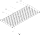
FIG.1 is a schematic diagram of a double-sided display of the present disclosure. -
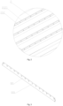
FIG.2 is an enlarged view of portion A shown inFIG. 1 . -
FIG.3 is a schematic diagram of a reinforcing rib of the double-sided display of the present disclosure. - In the drawings: 1, mounting frame; 101, fixing rod; 102, mounting rod; 1021, first mounting surface; 103, reinforcing rib; 1031, mounting groove; 104, fixing frame; 2, LED lamp bead.
- The present disclosure will be further described below with reference to the accompanying drawings and specific embodiments. It should be noted that, on the premise of no conflict, the embodiments or technical features described below can be arbitrarily combined to form new embodiments.
- As shown in
FIGS. 1-3 , the double-sided display of the present disclosure comprises a mounting frame 1 and at least two display modules. The mounting frame 1 comprises afirst mounting surface 1021 and a second mounting surface symmetrically arranged with thefirst mounting surface 1021. The at least two display modules are separately mounted on thefirst mounting surface 1021 and the second mounting surface. - In the present disclosure, the
first mounting surface 1021 and the second mounting surface configured to mount the at least two display modules are formed on the mounting frame 1, so that the double-sided display of the present disclosure performs double-sided display, so as to meet needs of users. - Optionally, the mounting frame 1 comprises two
fixing rods 101 and a plurality ofmounting rods 102 arranged between the twofixing rods 101. The twofixing rods 101 are parallelly arranged. The plurality ofmounting rods 102 are arranged at equal distances along a length direction of the fixing rods101. Two ends of each of the plurality ofmounting rods 102 are respectively fixed to the twofixing rods 101. The two fixing rods and the plurality of mounting rods form a grid shape. Thefirst mounting surface 1021 and the second mounting surface are formed on the plurality ofmounting rods 102. A plurality of LED lamp beads. 2 are arranged at equal distances along a length direction of thefirst mounting surface 1021 and the second mounting surface to form the at least two display modules The at least two display modules cooperates with each other to form an image. - In addition, in order to enhance a structural strength of the double-sided display of the present disclosure, the double-sided display further comprises a reinforcing
rib 103. The reinforcingrib 103 is arranged between the twofixing rods 101 and is arranged in parallel with the twofixing rods 101.Mounting grooves 1031 matched with the plurality ofmounting rods 102 are provided on the reinforcingrib 103. - During installation, the
mounting rods 102 are inserted into themounting grooves 1031 and then locked, so that the plurality ofmounting rods 102 are connected by the reinforcingrib 103. Then the two ends of each of the plurality ofmounting rods 102 are connected with the twofixing rods 101 to complete the installation of the double-sided display. - Meanwhile, in order to facilitate the installation of the double-sided display of the present disclosure,
fixing frames 104 are arranged on two ends of the mounting frame 1. Fixed holes are on thefixing frames 104. During use, a user can use bolts or other locking elements to mount thefixing frames 104 on a wall or an external fixing bracket. - Of course, the double-sided display further comprises a controller communicated with the at least two display modules. The user is able to control images displayed by the at least two display modules through the controller. An image displayed by a display module mounted on the
first mounting surface 1021 may be same or different with an image displayed by the other display module mounted on the second mounting surface. - Furthermore, in order to avoid loosening of the controller, a fixed groove configured to mount the controller is arranged in one of the fixing frames.
- By mounting the controller in the fixed groove and fixing the controller with bolts, the controller is effectively prevented from loosening. In the present disclosure, the controller is selected from a current conventional LED controller, which is not limited by the present disclosure, and the user can choose a suitable controller according to actual needs.
- The above-mentioned embodiments are only optional embodiments of the present disclosure, and are not intended to limit the protection scope of the present disclosure. Any insubstantial changes and replacements made by those skilled in the art based on the present disclosure should fall within the protection scope of the present disclosure.
Claims (4)
- A double-sided display, comprising: a mounting rack (1) and at least two display modules; wherein the mounting rack (1) comprises a first mounting surface (1021) and a second mounting surface symmetrically arranged with the first mounting surface (1021); the at least two display modules are separately mounted on the first mounting surface (1021) and the second mounting surface, wherein the double-sided display further comprises a controller communicating with the at least two display modules,
characterized in that,fixing frames (104) are arranged on two ends of the mounting rack (1); fixing holes are arranged on the fixing frames (104); the fixing frames are mountable on a wall or an external fixing bracket using locking elements through the fixing holes,wherein fixing grooves are arranged in the fixing frames (104); the controller is mounted on the fixing grooves with bolts. - The double-sided display according to claim 1, wherein the mounting rack (1) comprises two fixing rods (101) and a plurality of mounting rods (102) arranged between the two fixing rods (101); the two fixing rods (101) are parallelly arranged; the plurality of mounting rods (102) are arranged at equal distances along a length direction of the fixing rods (101); and two ends of each of the plurality of mounting rods (102) are respectively fixed to the two fixing rods (101); the two fixing rods and the plurality of mounting rods form a grid shape; the first mounting surface (1021) and the second mounting surface are formed on the plurality of mounting rods (102).
- The double-sided display according to claim 2, wherein the double-sided display further comprises a reinforcing rib (103); the reinforcing rib (103) is arranged between the two fixing rods (101) and is arranged in parallel with the two fixing rods (101); mounting grooves (1031) matched with the plurality of mounting rods (102) are provided on the reinforcing rib (103).
- The double-sided display according to claim 1, wherein the at least two display modules comprise a plurality of LED lamp beads (2).
Applications Claiming Priority (1)
| Application Number | Priority Date | Filing Date | Title |
|---|---|---|---|
| CN202122479386.7U CN216697693U (en) | 2021-10-14 | 2021-10-14 | Double-sided display |
Publications (3)
| Publication Number | Publication Date |
|---|---|
| EP4167217A1 EP4167217A1 (en) | 2023-04-19 |
| EP4167217C0 EP4167217C0 (en) | 2024-12-04 |
| EP4167217B1 true EP4167217B1 (en) | 2024-12-04 |
Family
ID=81748996
Family Applications (1)
| Application Number | Title | Priority Date | Filing Date |
|---|---|---|---|
| EP22174222.4A Active EP4167217B1 (en) | 2021-10-14 | 2022-05-19 | Double-sided display |
Country Status (4)
| Country | Link |
|---|---|
| US (1) | US20230120055A1 (en) |
| EP (1) | EP4167217B1 (en) |
| CN (1) | CN216697693U (en) |
| WO (1) | WO2023060667A1 (en) |
Family Cites Families (21)
| Publication number | Priority date | Publication date | Assignee | Title |
|---|---|---|---|---|
| US5900850A (en) * | 1996-08-28 | 1999-05-04 | Bailey; James Tam | Portable large scale image display system |
| US6741222B1 (en) * | 1999-07-13 | 2004-05-25 | Daktronics, Inc. | Panelized/modular electronic display |
| US8122627B2 (en) * | 2004-09-23 | 2012-02-28 | Daktronics, Inc. | Ventilated washable electronic sign display enclosure |
| US7823308B1 (en) * | 2007-05-31 | 2010-11-02 | Daktronics, Inc. | Electronic sign having a formed metal cabinet |
| CN101158781A (en) * | 2007-11-12 | 2008-04-09 | 杨忠义 | Double face LCD |
| CN201374158Y (en) * | 2009-02-05 | 2009-12-30 | 深圳市中庆微科技开发有限公司 | Double-sided LED screen |
| CN102235567A (en) * | 2010-04-23 | 2011-11-09 | 鸿富锦精密工业(深圳)有限公司 | Display device fixing frame |
| US8801264B2 (en) * | 2011-11-18 | 2014-08-12 | Shenzhen China Star Optoelectronics Technology Co., Ltd. | Back frame and backlight system of flat panel display device |
| EP2793652B1 (en) * | 2011-12-19 | 2018-08-15 | Hidden View Oy | An arrangement for fastening elements to a wall |
| US9666105B2 (en) * | 2013-03-16 | 2017-05-30 | ADTI Media, LLC | Sign construction with modular wire harness arrangements and methods of using same for backside to frontside power and data distribution schemes |
| US9852666B2 (en) * | 2013-03-16 | 2017-12-26 | Adti Media Llc | Full height sectional sign assembly and installation kit and method of using same |
| US9416551B2 (en) * | 2013-12-31 | 2016-08-16 | Ultravision Technologies, Llc | Preassembled display systems and methods of installation thereof |
| CN204288710U (en) * | 2014-11-14 | 2015-04-22 | 深圳市洲明科技股份有限公司 | LED display |
| CN204795339U (en) * | 2015-03-25 | 2015-11-18 | 广东长虹电子有限公司 | Novel two -sided LED display screen |
| CN205943366U (en) * | 2016-06-24 | 2017-02-08 | 深圳市赫尔诺电子技术有限公司 | Two -sided display lamp strip and two -sided display screen |
| DE102016122922A1 (en) * | 2016-11-28 | 2018-05-30 | ANNAX GmbH | Double-sided screen with shared backlight |
| CN107784945A (en) * | 2017-11-24 | 2018-03-09 | 江苏飞视文化发展有限公司 | A kind of double-sided display billboard |
| KR102464234B1 (en) * | 2018-02-28 | 2022-11-07 | 삼성전자주식회사 | Display appartus |
| WO2020040616A1 (en) * | 2018-08-24 | 2020-02-27 | Samsung Electronics Co., Ltd. | Display apparatus |
| CN209767686U (en) * | 2019-03-25 | 2019-12-10 | 深圳创维-Rgb电子有限公司 | Double-sided TV with double-sided lamination and full-screen |
| CN111223416A (en) * | 2020-03-12 | 2020-06-02 | 安徽富煌科技股份有限公司 | Transparent LED electronic stop board |
-
2021
- 2021-10-14 CN CN202122479386.7U patent/CN216697693U/en active Active
- 2021-11-02 WO PCT/CN2021/128215 patent/WO2023060667A1/en not_active Ceased
-
2022
- 2022-05-06 US US17/738,021 patent/US20230120055A1/en not_active Abandoned
- 2022-05-19 EP EP22174222.4A patent/EP4167217B1/en active Active
Also Published As
| Publication number | Publication date |
|---|---|
| EP4167217A1 (en) | 2023-04-19 |
| CN216697693U (en) | 2022-06-07 |
| US20230120055A1 (en) | 2023-04-20 |
| EP4167217C0 (en) | 2024-12-04 |
| WO2023060667A1 (en) | 2023-04-20 |
Similar Documents
| Publication | Publication Date | Title |
|---|---|---|
| KR20050010942A (en) | Liquid crystal display device | |
| CN211694274U (en) | Arc-shaped mounting and fixing structure of LED display screen box body | |
| EP4167217A1 (en) | Double-sided display | |
| CN208315115U (en) | A kind of splicing LED display | |
| CN216520570U (en) | Quick installing support of LED screen concatenation | |
| CN211555362U (en) | LED display screen convenient to overhaul | |
| CN216487106U (en) | LED display screen with dustproof construction | |
| CN212900502U (en) | Wireless LED display screen of thing networking | |
| CN205003985U (en) | Full -color glass LED display screen | |
| CN221121622U (en) | LED display screen structure of slidingtype installation | |
| CN213206208U (en) | Corner section bar for LED screen frame | |
| CN219457081U (en) | Seamless high-definition LED display screen | |
| CN214119607U (en) | Connect stable anti-drop's LED display screen mounting structure | |
| CN217928149U (en) | LED display screen structure frame capable of being assembled quickly | |
| CN221281695U (en) | LED spliced display screen | |
| CN221446435U (en) | Backlight module and screen | |
| CN219225812U (en) | Novel spliced screen display unit | |
| CN222088237U (en) | Back frame and display screen | |
| CN213424454U (en) | Aluminum-shell LED display screen | |
| CN222192723U (en) | Aluminum profile box for mounting LED lamp panel | |
| CN218929494U (en) | LED transportation is with carrier vehicle | |
| CN213070463U (en) | High life LED display screen convenient to dismouting | |
| CN220540669U (en) | LED screen convenient to installation | |
| CN220646367U (en) | Assembled LED digital screen | |
| CN217506852U (en) | Split type lamp box |
Legal Events
| Date | Code | Title | Description |
|---|---|---|---|
| PUAI | Public reference made under article 153(3) epc to a published international application that has entered the european phase |
Free format text: ORIGINAL CODE: 0009012 |
|
| STAA | Information on the status of an ep patent application or granted ep patent |
Free format text: STATUS: THE APPLICATION HAS BEEN PUBLISHED |
|
| AK | Designated contracting states |
Kind code of ref document: A1 Designated state(s): AL AT BE BG CH CY CZ DE DK EE ES FI FR GB GR HR HU IE IS IT LI LT LU LV MC MK MT NL NO PL PT RO RS SE SI SK SM TR |
|
| STAA | Information on the status of an ep patent application or granted ep patent |
Free format text: STATUS: REQUEST FOR EXAMINATION WAS MADE |
|
| 17P | Request for examination filed |
Effective date: 20231017 |
|
| RBV | Designated contracting states (corrected) |
Designated state(s): AL AT BE BG CH CY CZ DE DK EE ES FI FR GB GR HR HU IE IS IT LI LT LU LV MC MK MT NL NO PL PT RO RS SE SI SK SM TR |
|
| STAA | Information on the status of an ep patent application or granted ep patent |
Free format text: STATUS: EXAMINATION IS IN PROGRESS |
|
| 17Q | First examination report despatched |
Effective date: 20231213 |
|
| GRAP | Despatch of communication of intention to grant a patent |
Free format text: ORIGINAL CODE: EPIDOSNIGR1 |
|
| STAA | Information on the status of an ep patent application or granted ep patent |
Free format text: STATUS: GRANT OF PATENT IS INTENDED |
|
| GRAS | Grant fee paid |
Free format text: ORIGINAL CODE: EPIDOSNIGR3 |
|
| INTG | Intention to grant announced |
Effective date: 20240930 |
|
| GRAA | (expected) grant |
Free format text: ORIGINAL CODE: 0009210 |
|
| STAA | Information on the status of an ep patent application or granted ep patent |
Free format text: STATUS: THE PATENT HAS BEEN GRANTED |
|
| AK | Designated contracting states |
Kind code of ref document: B1 Designated state(s): AL AT BE BG CH CY CZ DE DK EE ES FI FR GB GR HR HU IE IS IT LI LT LU LV MC MK MT NL NO PL PT RO RS SE SI SK SM TR |
|
| REG | Reference to a national code |
Ref country code: CH Ref legal event code: EP |
|
| REG | Reference to a national code |
Ref country code: DE Ref legal event code: R096 Ref document number: 602022008309 Country of ref document: DE |
|
| REG | Reference to a national code |
Ref country code: IE Ref legal event code: FG4D |
|
| U01 | Request for unitary effect filed |
Effective date: 20241204 |
|
| U07 | Unitary effect registered |
Designated state(s): AT BE BG DE DK EE FI FR IT LT LU LV MT NL PT RO SE SI Effective date: 20241216 |
|
| PG25 | Lapsed in a contracting state [announced via postgrant information from national office to epo] |
Ref country code: HR Free format text: LAPSE BECAUSE OF FAILURE TO SUBMIT A TRANSLATION OF THE DESCRIPTION OR TO PAY THE FEE WITHIN THE PRESCRIBED TIME-LIMIT Effective date: 20241204 |
|
| PG25 | Lapsed in a contracting state [announced via postgrant information from national office to epo] |
Ref country code: ES Free format text: LAPSE BECAUSE OF FAILURE TO SUBMIT A TRANSLATION OF THE DESCRIPTION OR TO PAY THE FEE WITHIN THE PRESCRIBED TIME-LIMIT Effective date: 20241204 |
|
| PG25 | Lapsed in a contracting state [announced via postgrant information from national office to epo] |
Ref country code: NO Free format text: LAPSE BECAUSE OF FAILURE TO SUBMIT A TRANSLATION OF THE DESCRIPTION OR TO PAY THE FEE WITHIN THE PRESCRIBED TIME-LIMIT Effective date: 20250304 |
|
| PG25 | Lapsed in a contracting state [announced via postgrant information from national office to epo] |
Ref country code: GR Free format text: LAPSE BECAUSE OF FAILURE TO SUBMIT A TRANSLATION OF THE DESCRIPTION OR TO PAY THE FEE WITHIN THE PRESCRIBED TIME-LIMIT Effective date: 20250305 |
|
| PG25 | Lapsed in a contracting state [announced via postgrant information from national office to epo] |
Ref country code: RS Free format text: LAPSE BECAUSE OF FAILURE TO SUBMIT A TRANSLATION OF THE DESCRIPTION OR TO PAY THE FEE WITHIN THE PRESCRIBED TIME-LIMIT Effective date: 20250304 |
|
| U20 | Renewal fee for the european patent with unitary effect paid |
Year of fee payment: 4 Effective date: 20250528 |
|
| PG25 | Lapsed in a contracting state [announced via postgrant information from national office to epo] |
Ref country code: SM Free format text: LAPSE BECAUSE OF FAILURE TO SUBMIT A TRANSLATION OF THE DESCRIPTION OR TO PAY THE FEE WITHIN THE PRESCRIBED TIME-LIMIT Effective date: 20241204 |
|
| PG25 | Lapsed in a contracting state [announced via postgrant information from national office to epo] |
Ref country code: PL Free format text: LAPSE BECAUSE OF FAILURE TO SUBMIT A TRANSLATION OF THE DESCRIPTION OR TO PAY THE FEE WITHIN THE PRESCRIBED TIME-LIMIT Effective date: 20241204 |
|
| PG25 | Lapsed in a contracting state [announced via postgrant information from national office to epo] |
Ref country code: IS Free format text: LAPSE BECAUSE OF FAILURE TO SUBMIT A TRANSLATION OF THE DESCRIPTION OR TO PAY THE FEE WITHIN THE PRESCRIBED TIME-LIMIT Effective date: 20250404 |
|
| PG25 | Lapsed in a contracting state [announced via postgrant information from national office to epo] |
Ref country code: SK Free format text: LAPSE BECAUSE OF FAILURE TO SUBMIT A TRANSLATION OF THE DESCRIPTION OR TO PAY THE FEE WITHIN THE PRESCRIBED TIME-LIMIT Effective date: 20241204 |
|
| PG25 | Lapsed in a contracting state [announced via postgrant information from national office to epo] |
Ref country code: CZ Free format text: LAPSE BECAUSE OF FAILURE TO SUBMIT A TRANSLATION OF THE DESCRIPTION OR TO PAY THE FEE WITHIN THE PRESCRIBED TIME-LIMIT Effective date: 20241204 |
|
| PLBE | No opposition filed within time limit |
Free format text: ORIGINAL CODE: 0009261 |
|
| STAA | Information on the status of an ep patent application or granted ep patent |
Free format text: STATUS: NO OPPOSITION FILED WITHIN TIME LIMIT |
|
| REG | Reference to a national code |
Ref country code: CH Ref legal event code: L10 Free format text: ST27 STATUS EVENT CODE: U-0-0-L10-L00 (AS PROVIDED BY THE NATIONAL OFFICE) Effective date: 20251015 |
|
| 26N | No opposition filed |
Effective date: 20250905 |
|
| REG | Reference to a national code |
Ref country code: CH Ref legal event code: H13 Free format text: ST27 STATUS EVENT CODE: U-0-0-H10-H13 (AS PROVIDED BY THE NATIONAL OFFICE) Effective date: 20251223 |
|
| PG25 | Lapsed in a contracting state [announced via postgrant information from national office to epo] |
Ref country code: CH Free format text: LAPSE BECAUSE OF NON-PAYMENT OF DUE FEES Effective date: 20250531 |
|
| PG25 | Lapsed in a contracting state [announced via postgrant information from national office to epo] |
Ref country code: MC Free format text: LAPSE BECAUSE OF FAILURE TO SUBMIT A TRANSLATION OF THE DESCRIPTION OR TO PAY THE FEE WITHIN THE PRESCRIBED TIME-LIMIT Effective date: 20241204 |
|
| PG25 | Lapsed in a contracting state [announced via postgrant information from national office to epo] |
Ref country code: IE Free format text: LAPSE BECAUSE OF NON-PAYMENT OF DUE FEES Effective date: 20250519 |